FEATURES
• Units 5 thru 15 kW are field
convertible from single to three phase
• 24 volt low voltage control circuit is
,V802 ,Wk 5 ro 3 no tpecxe dradnats
240/208V, or 277V units which have
line voltage control
• Heavy-duty totally enclosed motors
• Aluminum finned, copper clad,
steel sheath heating elementI
• Advanced inlet louver design draws
cool air across heating element
for more efficient operation
• Automatic reset linear thermal
protector
• Venturi outlet with large dynamically
balanced fan blade
• Heavy gauge die-formed steel housing
• Optional vertical and horizontal
brackets available
Form 5S5542
E
N
G
L
I
S
H
E
S
P
A
Ñ
O
L
F
R
A
N
Ç
A
I
S
Printed in USA
09663
04/2023
Dayton
®
Heavy-Duty
Electric Unit Heaters
Operating Instructions & Parts Manual 804RZ6 thru 804RZ9, 804T01 thru 804T22
Please read and save these instructions. Read carefully before attempting to assemble, install, operate
or maintain the product described. Protect yourself and others by observing all safety information. Failure to comply with instructions could
result in personal injury and/or property damage! Retain instructions for future reference.
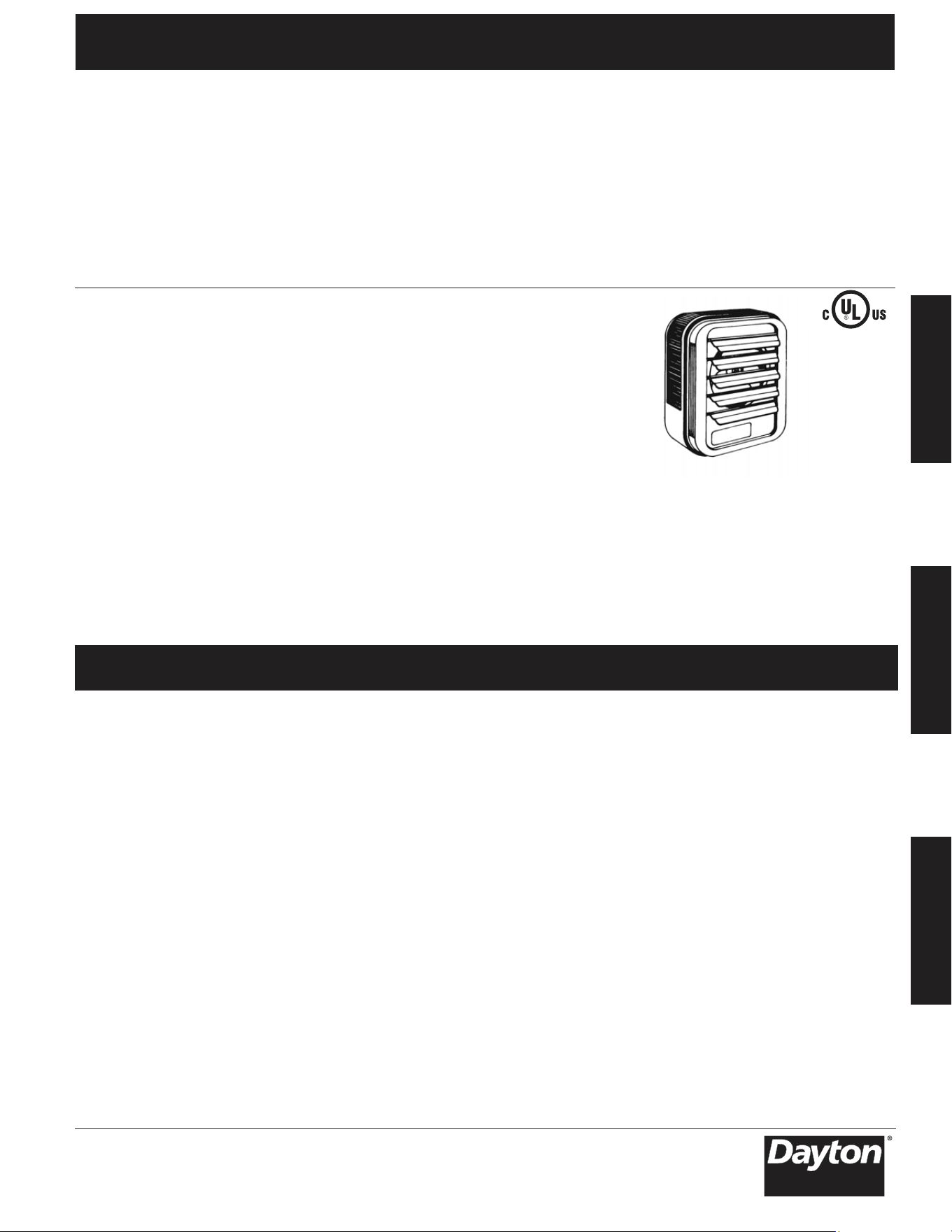
Figure 1
Unpacking
Remove the heater from the box and
inspect it for any damage. If it appears
to be damaged, immediately return.
Check the contents of the box to make
sure it contains one heating unit.
(**) Must use two-stage Thermostat on 3Ø operation.
(*) These models are wired for direct line voltage control.
Heater/ Amps Air Air
kW BTU/HR Motor Control Per Fan Motor CFM at FPM at Temp. Throw
Model Rating (1,000’s) Voltage Phase Voltage Phase HP RPM Outlet Outlet Rise (°F) (Horiz)
Description
Dayton Heavy-Duty Electric Heaters are designed for continuous or intermittent use
in factories, warehouses, public buildings, stock rooms, service stations, any large or
exposed areas, or additions. Can be installed for use in downflow or horizontal
applications.
Specifications
5200-11259-000
ISS 1.0-003
ECR-02717
804T10* 2.2/3.0 7.5/10.2 208/240 1 208/240 11.0/12.5 1/100 1600 350 800 27
804T12 3 10.2 480 3 24 3.6 1/100 1600 350 800 27
804T11* 3 10.2 277 1 277 11 1/100 1600 350 800 27
804T09* 3 10.2 208 1 208 14.5 1/100 1600 350 800 27
804T17*(**)
3.7/5.0 12.6/17.0 208/240 1-3 208/240 18.0/21.0 1/100 1600 350 800 45
804T19 5 17 480 3 24 6 1/100 1600 350 800 45
804T18* 5 17 277 1 277 18 1/100 1600 350 800 45
804T16*(**)
5 17 208 1-3 208 24.0/13.9 1/100 1600 350 800 45
804T21 5.6/7.5 19.1/25.6 208/240 1-3 24 27.0/31.3 1/30 1600 650 970 37
804T22 7.5 25.6 480 3 24 9 1/30 1600 650 970 37
804T20 7.5 25.6 208 1-3 24 36/20.8 1/30 1600 650 970 37
804RZ7 7.5/10.0 25.6/34.1 208/240 1-3 24 36.0/42.0 1/30 1600 650 970 49
804RZ8 10 34.1 480 3 24 12 1/30 1600 650 970 49
804RZ6 10 34.1 208 1-3 24 48.0/27.7 1/30 1600 650 970 49
804T01 11.2/15.0 38.2/51.2 208/240 3 24 31.3/36.1 1/20 1530 910 1640 52
804T02 15 51.2 480 3 24 18 1/20 1530 910 1640 52
804RZ9 15 51.2 208 1-3 24 72.0/41.6 1/20 1530 910 1640 52
804T03 15.0/20.0 51.2/68.2 208/240 3 24 41.2/48.0 1/10 1500 1320 2060 48
804T04 20 68.2 480 3 24 24 1/10 1500 1320 2060 48
804T05 25 85.2 480 3 24 30 1/4 1600/1375 2100/1800 2100/2030 38/44 50
804T07 22.5/30.0 76.7/102.3 208/240 3 24 63.0/72.3 1/4 1600/1375 2100/1800 2100/2030 45/53 50
804T08 30 102.3 480 3 24
804T06 30 102.3 208 3 24
804T13 40 136.4 480 3 24
804T14 37.5/50.0 127.3/170.5 208/240 3
804T15 50 170.5 480 3 24 60.2 1/2 1525/1420 3000/2600 3260/2900 53/61 60
12
12
12
12
12
12
12
12
18
18
18
18
18
18
35
35
35
41
41
1/4 1600/1375 2100/1800 2100/2030 45/53 50
1/4 1600/1375 2100/1800 2100/2030 45/53 50
1/2 1525/1420 3000/2600 3260/2900 42/49 60
36
84
48
24 104.2/120.0 1/2 1525/1420 3000/2600 3260/2900 53/61 60
2
E
N
G
L
I
S
H
IMPORTANT
INSTRUCTIONS
When using electric
appliances, basic
precautions should always be followed
to reduce the risk of fire, electric shock,
and injury to persons, including the
following:
1. Read all instructions before installing
or using this heater.
2. This heater is a commercial/industrial
product not intended for use in a
residential setting.
3. This heater is hot when in use. To
avoid burns, do not let bare skin
touch hot surfaces. Keep combustible
mate
rials, such as furniture, pillows,
bedding, papers, clothes, etc. and
curtains at least 3 feet (0.9 m) from
the front of the heater.
4. Extreme caution is necessary when
any heater is used by or near children
or invalids and whenever the heater
is left operating and unattended.
5. This heater has hot and arcing or
sparking parts inside and is not
intended for use in hazardous
atmospheres where flammable
vapors, gases, liquids or other
combustible atmospheres as defined
in the
National Electrical Code are
used or stored. Failure to comply
can result in explosion or fire.
6. Do not operate any heater after it
malfunctions. Disconnect power at
main service panel and have hea
ter
inspected by a reputable electrician
before using.
7. Do not use outdoors.
8. To disconnect heater, turn controls
to off, and turn off power to heater
circuit at main service panel.
9. Do not insert or allow foreign objects
to enter any ventilation or exhaust
opening as this may
cause an electric
shock, fire, or damage to the heater.
10. To prevent a possible fire, do not
block air intake or exhaust in any
manner.
11. Use this heater only as described
in this manual. Any other use not
recommended by the manufacturer
may cause fire, electric shock,
or injury to persons.
12. This heater is not intended for use
in special environments. Do not use
in damp or wet locations such as
marine or greenhouse or in areas
where corrosive or chemical agents
are present.
1
3. When installing, see INSTALLATION
INSTRUCTIONS for additional
warnings and precautions.
14. For safe and efficient operation,
and to extend the life of your
heater, keep your heater clean.
See MAINTENANCE INSTRUCTIONS.
Installation
Instructions
To prevent a
possible fire, injury
to persons or damage to the heater,
adhere to the following:
1. Disconnect all power coming to
heater at main service panel before
wiring or servicing.
IMPORTANT NOTE: This heater must
be i
nstalled byaqualified person.
2. All wiring procedures and
connections must be in accordance
with the National and Local Codes
having jurisdiction and the heater
must be grounded.
3. Verify the power supply voltage
coming to heater matches the ratings
as shown on the heater nameplate.
Energizing heater
at a voltage greater
than the voltage printed on the
nameplate will damage the heater
and void the warranty and could
cause a fire.
4. To reduce the risk of fire, do not store
or use gasoline or other flammable
vapors and liquids in the vicinity of
the heater.
5. The ceiling or wall mounting structure
and the anchoring provisions must be
of sufficient strength to support the
combined weight of the heater and
mounting bracket.
6. All built-in thermostats: If the heater
is used to prevent piping or liquids
from freezing, and if the thermostat
is set below 45°F (7°C), the fan must
run continuously.
7. The heater must be mounted at least
7’ (2134 mm) above
the floor to avoid
accidental contact with the fan blade
which could cause injury.
8. Keep at least 5’ clearance in front of
the heater. Refer to Table 1 for side,
top and back clearance requirements.
9. Do not mount mercury type
thermostat directly on unit. Vibration
could cause heater to malfunction.
HEATER LOCATION
1. Arrange units so their discharge air
streams are subjected to a minimum
of interference from columns and
partitions.
2. Direct air stream away from room
occu
pants in comfort heating.
3
. Air streams should wipe exposed wall
without blowing directly at them.
Dayton Operating Instructions and Parts Manual
Dayton
®
Heavy-Duty Electric
Unit Heaters
804RZ6 thru 804RZ9, 804T01 thru 804T22
3
E
N
G
L
I
S
H
Dayton Operating Instructions and Parts Manual
Installation
Instructions
(Continued)
4. Direct air stream along the windward
side of a room when installed in a
building exposed to a prevailing wind.
5. If using a remote thermostat, locate
thermostat approximately 5 feet
above the floor on the interior
partition walls or posts away from cold
drafts, internal heat sources, and away
from heater discharge air streams.
6. Large rooms require multi-unit
installations. Arrange units to provide
perimeter air circulation w
here
each unit supports the air stream
from another.
MOUNTING
GENERAL (See Table 3, page 4, for
Mounting Accessories)
1. Position the heater so access door can
be opened to provide access to the
wiring and control compartment. If
the heater is to be mounted with the
access door facing a wall, the heater
must be mounted far enough from
that wall to allow full opening of the
access door (approximately equal to
the depth of the heater). Refer to
Table 1.
2. Heater may be mounted for ver
tical
or horizontal discharge by the use
of threaded rods. Refer to Table 2.
3. Optional mounting brackets permit
horizontal pivoting of heater.
4. Louvers may be positioned to direct
heated air in desired direction. For
horizontal discharge, louvers should
direct air either straight ahead
or downward.
3 & 5 kW Horiz. 2 (50.8) 6 (152.4) 9 (228.6) 2YV16
Vert. 6 (152.4) 18 (457.2) 18 (457.2) 2YU84
7.5 to 10 kW Horiz. 6 (152.4) 6 (152.4) 13 (330.2) 2YV16
Vert. 6 (152.4) 24 (609.6) 2
4 (609.6) 2YU84
15 to 20 kW Horiz. 6 (152.4) 9 (228.6) 12
1
/2 (317.5) 2YV17
Vert 6 (152.4) 24 (609.6) 24 (609.6) 2YU84
25 to 50 kW Horiz. 16 (406.4) 12 (304.8) 18
1
/2 (470.0) 2YU91 & 92
Vert. 12 (304.8) 36 (914.4) 36 (914.4) 2YU85
Table1– Wall and Ceiling Clearance, inches (mm) / Mounting Brackets
Optional
Mounting
Unit Discharge Ceiling Side Wall Back Wall Brackets
3 - 5kW 5/16”-18 6
1
/16” 6” 4
1
/16” 3/4” 6” 9
3
/4” 2” 4
3
/16”
7.5 - 10 5/16-18 6
1
/16 8
7
/8 5
1
/8 3/4 8
7
/8 14
5
/8 2 5
1
/8
15 - 20 5/16-18 11
3
/8 8
7
/8 5
1
/8 3/4 8
7
/8 14
7
/8 2 5
1
/8
25 - 30 3/8-16 10
9
/16 14
1
/2 6
3
/16 5/8 14
1
/2 21
1
/4 2
3
/16 6
3
/16
40 - 50 3/8-16 15
15
/16 14
1
/2 6
3
/16 5/8 — — — —
Table2– Mounting Rod Spacing
Rod (Figure 2) (Figure 3)
Thread Horizontal Vertical
Unit Type A B C D E F G H
Models 804RZ6 thru 804RZ9, 804T01 thru 804T22
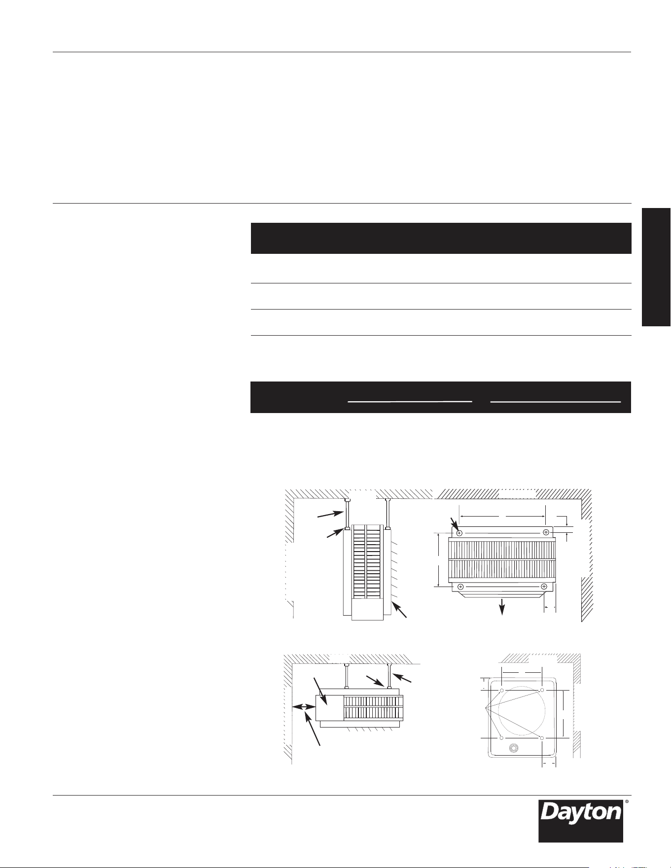
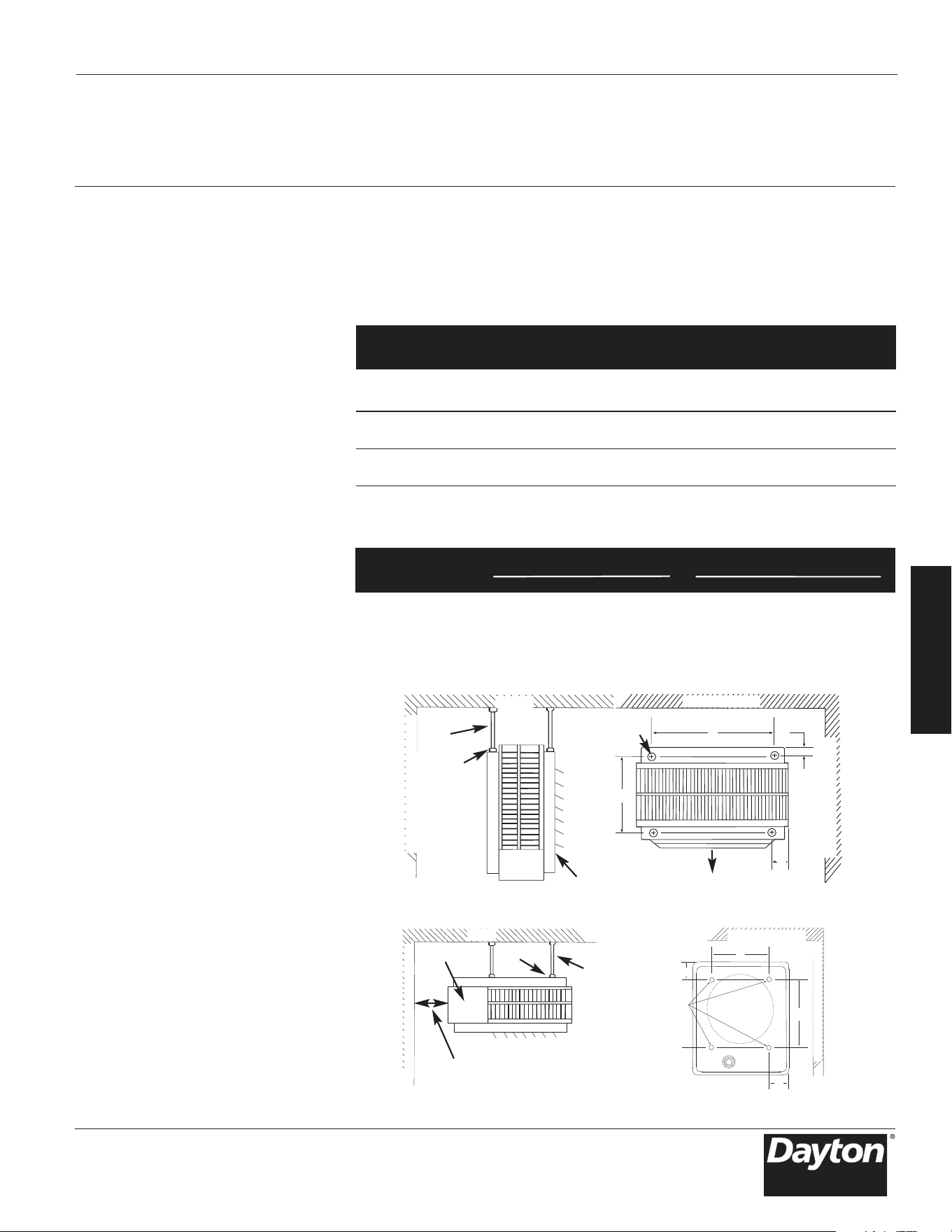
Figure 2. Horizontal Discharge Mounting and Spacing.
CEILING
BACK WALL
B
A
C
K
W
A
L
L
S
I
D
E
W
A
L
L
MOUNTING
ROD
LOCK NUT
UNIT HEATER
THREADED
MOUNTING
HOLES
B
A
D
C
(TOP VIEW)
Figure 3. Vertical Discharge Mounting and Rod Spacing
CEILING
B
A
C
K
W
A
L
L
S
I
D
E
W
A
L
L
ACCESS
DOOR
MOUNTING
ROD (4)
THREADED
MOUNTING
HOLES
CLEARANCE EQUAL TO WIDTH OF
HEATER TO PERMIT FULL OPEN-
ING OF THE ACCESS DOOR
LOCK NUT
BACK WALL
E
H
F
G
(TOP VIEW)

2YU34 Radial Diffuser Kit Use only on 7.5 thru 20kW heaters (804T01 thru 804T04,
804T20 thru 804T22, 804RZ6 thru 804RZ9)
Use only on 25 thru 50W heaters (804T06 thru 804T08,
804T14, 804T15, 804T05, and 804T13)
2YU83 Vertical Discharge Ceiling Mounting Bracket Kit Use only on 3 and 5kW heaters (804T09 thru 804T12, and
2YU84 Vertical Discharge Ceiling Mounting Bracket Kit Use only on 7.5 thru 20kW heaters (804T01 thru 804T04,
2YU85 Vertical Discharge Ceiling Mounting Bracket Kit
2YV16 Universal Wall and Ceiling Mounting Bracket Kit Use only on 3 thru 10kW heaters (804T09 thru 804T12,
2YV17 Universal Wall and Ceiling Mounting Bracket Kit Use only on 15 and 20kW heaters (804T01 thru 804T04,
2YU91 Universal Wall and Ceiling Mounting Bracket Kit Use only on 25kW and 30kW heaters(804T05 thru 804T08)
2YU92 Universal Wall and Ceiling Mounting Bracket Kit Use only on 40kW and 50kW heaters
(804T13 thru 804T15)
2YU33 Single pole internal thermostat All Dayton Unit heaters
Temp range 40°F - 85°F
2YU95 Two stage internal thermostat
Can only be used on 804T06, 804T07, 804T09, 804T10,
804T11, 804T14, and 804T15
Temp range 40°F - 85°F
2YU82 Internal summer fan switch All Dayton Unit heaters
2YU90 Internal heat recovery thermostat with relay
Can only be used on 804T09, 804T10, 804T11,
and 804T18
(24 V coil - single pole normally open)
2YU93 25 amp 3 pole power disconnect switch
Can only be used on 804T02, 804T04, 804T09, 804T10, 804T11,
804T12, 804T16, 804T17, 804T18, 804T19, 804T22, and 804RZ
8
rated 25 amps resistive @ 600 volts
2YU94 60 amp 3 pole power disconnect switch Can only be used on 804RZ9 (When wired for 3 phase),
804T01, 804T04, 804T05, 804T08, 804T13, 804T21,and 804RZ7
rated 60 amps resistive @ 600 volts
4
E
N
G
L
I
S
H
Installation
Instructions
(Continued)
ROD MOUNTING
HORIZONTAL DISCHARGE
1. Install four threaded mounting rods
in the threaded holes and secure in
place using lock nuts. (See Table 2.)
2. Securely attach the four mounting
rods to the ceiling. (Refer to Table 1
for wall and ceiling clearances, and
Table 2 for mounting rod spacing.)
VERTICAL DISCHARGE
1. Remove bolts from the threaded
holes in the back of the heaters.
2. Install four threaded mounting rods
in the thr
eaded holes and secure in
place using lock nut
s.
3. Securely attach the four mounting
rods to the ceiling
. (Refer to Table 1
for wall and ceiling clearances, and
Table 2 for mounting rod spacing
dimensions.)
WIRING
BRANCH CIRCUIT (POWER)
1. Connect heater only to the voltage,
amperage and frequency specified
on the nameplate.
2. Field wiring must be properly sized
to carry the amperage in accordance
with the NEC.
3. The access door is hinged. There are
either one or two screws a
ccessible
from the bottom that must be
removed to gain access.
Dayton Operating Inst
ructions and Parts Manual
Dayton
®
Heavy-Duty Electric
Unit Heaters
Electrical
Accessory Description Product Compatability Notes
Mechanical
Accessory Description Product Compatability Notes
Table3– Optional Accessories
804RZ6 thru 804RZ9, 804T01 thru 804T22
804T16 thru 804T19)
804T20 thru 804T22, and 804RZ6 thru 804RZ9)
804T16 thru 804T22, and 804RZ6 thru 804RZ8)
and 804RZ9)
5
E
N
G
L
I
S
H
Installation
Instructions
(Continued)
4. A knockout is provided in the back
of the heater close to the power
terminal board. The control terminal
board knockout is 1/2 inch conduit
size. The power terminal block
knockout is multiple diameter. Use
the diameter that fits the required
conduit size.
5. A ground terminal is provided
near the power terminal board. The
ground wire should be connected
before other connections are made.
6. The power terminal board is equipped
with
box terminals sized to accept the
correct size power supply wir
e. Wire
rated at 600V and 60°C is satisfactory
for the heater branch circuit. Either
aluminum or copper wire is satisfactory
for connection to the heater power
terminal board box terminal.
Copper wire is recommended.
7. Each heater has a wiring diagram
affixed to the inside of the access
door. Consult this diagram before
making any field connections.
8. Single or three-phase connections
phase operation. If these heaters
are for use with three-phase power,
reconnect the wires as indicated in
the wiring diagram attached to
the he
ater.
a. Additional information can be
found by looking at the wiring
illustrations in Figures 4a through
and following th
e directions
under “Control Wiring”.
b. On Models 804T16, 804T17, 804T20,
804T21, 804RZ6, and 804RZ7 (Figures
4a and 4b)move only the two wires
marked “A1” and “B1”; do not
move or change any other wiring.
The element lead wire marked “B1”
which is factory connected to the
power terminal block
moved
must be
to terminal “B”on the
three-phase terminal block.
Dayton Operating Instructions and Parts Manual
may be used with heater models
804T16, 804T17, 804T20, 804T21
804RZ6, 804RZ7, and 804RZ9. These
units are factory wired for single
A
B
A
B
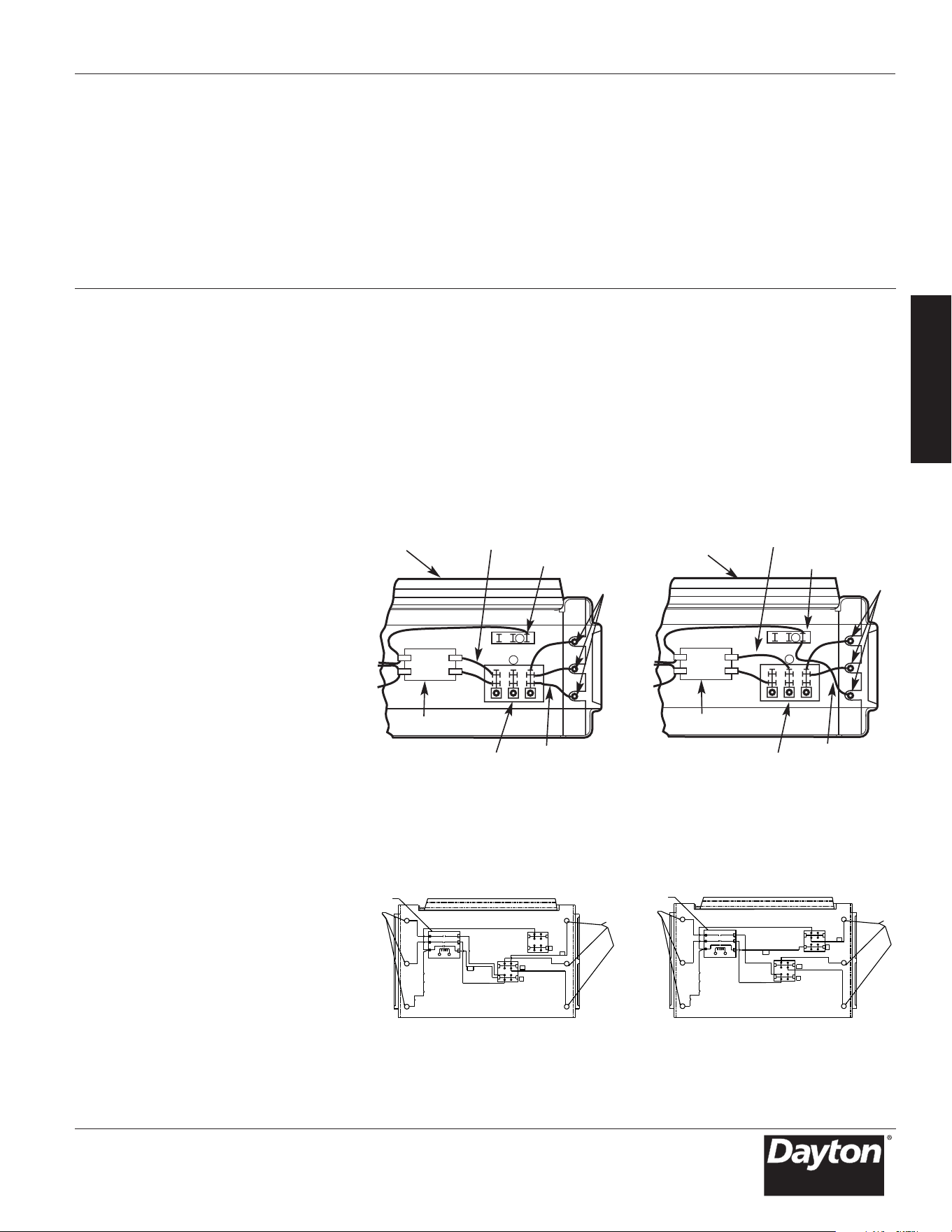
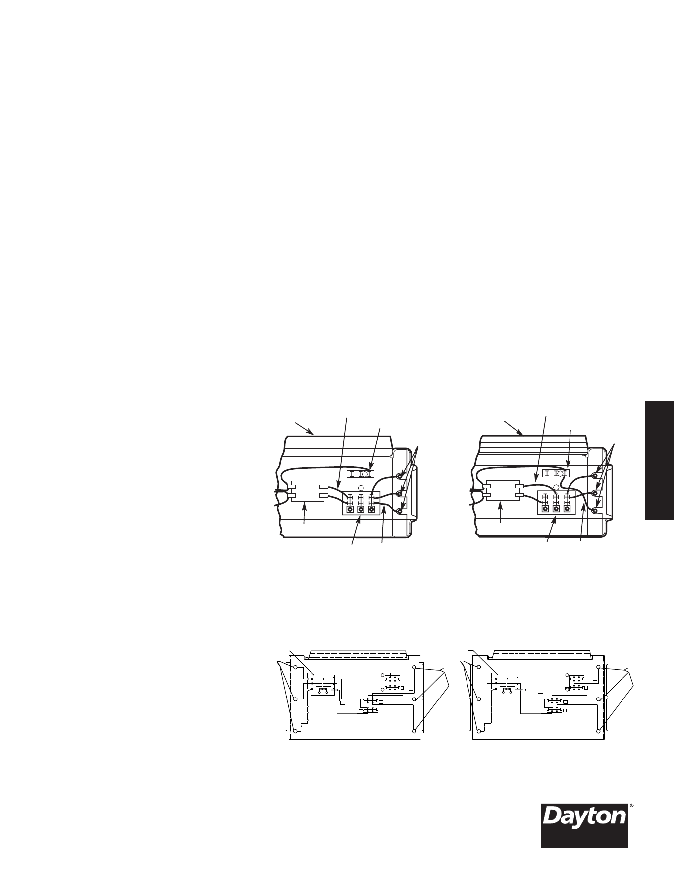
Figure 4a – Wiring Connections for Single-Phase and Three-Phase Power
(804T16, 804T17, 804T20, 804T21)
and Three-Phase Power (804RZ6
Heater Front
Heater Front
Elements
Lead Wire “A1”
3 Phase Block
Elements
Lead Wire “A1”
3 Phase Block
Lead Wire “B1”
Power Terminal Block
Contactor (or P2)
Lead Wire “B1”
Power Terminal Block
Contactor (or P2)
To Elements
To Elements
Field-Wired for Three-Phase PowerFactory-Wire
Three-Phase AlternativeSingle-Phase Alternative
d for Single-Phase Power
Figure 4b–Wiring Connections for Single-Phase
IMPORTANT NOTE: Installation Screw
Lug Torque – during trans
portation it
is possible screw lug connections can
loosen.
After installation, before power
is turned on to the heater, check all
screw lug connections for tightness to
the recommended minimum torque on
the label affixed to the unit.
4c
and 804RZ7)
(3) ELEMENTS
CONTACTOR
POWER TERMINAL BLOCK
L2
A1
L3
L1
B1
(3) ELEMENTS
A
B
1
2
3
(3) ELEMENTS
(3) ELEMENTS
CONTACTOR
POWER TERMINAL BLOCK
3-PHASE
BLOCK
A
L2
L3
A1
C
B
A
L1
B1
B
1
2
3
1
2
3
Models 804RZ6 thru 804RZ9, 804T01 thru 804T22
E
N
G
L
I
S
H
Installation
Instructions
(Continued)
c. For 804RZ6 and 804RZ7, wire “A1”
must be moved from the power
terminal block to the “A” terminal
of the 3-phase terminal block. For
804T16, 804T17, 804T20, and 804T21
wire “A1” must be moved to the
“A” (middle) terminal of the power
terminal block.
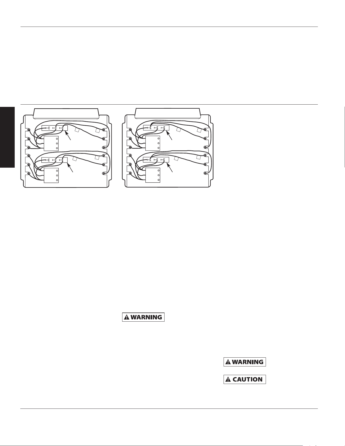
d. Model 804RZ9 (Figure 4b) has
two three-phase terminal blocks
located adjacent to the relays
(contactors). Move only the two
wires marked “C1” and “D1” on
each of these two three-phase
terminal b
locks to terminal “B”.
Do not move or change any
other wires.
9. Electrical Accessories, either kits
or factory-installed options, are
shown connected by a dashed
line on the heater wiring diagram.
10. 208/240 VOLT HEATER. The heaters
are wired for 240V from facto
ry.
When heater is to be connected to
208V supply, the transformer leads
have to be interchanged. For model
804T14, interchange ORANGE and
RED primary leads. The black colore
d
6
lead is the COMMON for the 50VA
transfor
mer provided with this
model. For the other models,
interchange BLACK and RED primary
leads. The WHITE colored lead is the
COMMON for the 40VA control
transformer provide
d with these
heaters. Always refer to the wiring
diagram on the cover of the heater
before making this reconnection
of transformer primary leads.
CONTROL WIRING
Line voltage is
present on some o
f
the terminals on the control terminal
board. Always disconnect the power
from the heater before making any
connections to the control board to
prevent hazard.
1. Use min. 600 volt, NEC Class 1
insulated wire for all control circuit
wiring.
2. Use a crimp-on type fork terminal
on the wire ends that attach to the
control terminal board if more than
one connection is to be made under
the terminal screw.
3. On units not provided with internal
contactor (3 kW), refer to Figure 5,
page 8, for wiring diagram.
NOTE: Thermostat and control circuit
wiring must be suitable to handle the
full load of the
heater (example
804T09 is rated 24 amps).
4. On units provided with internal
contactor (units rated 5 kW and
higher) refer to Figure 6, page 8,
for wiring diagram. Control wiring
must be rated minimum 18 AWG.
Operation
Instructions
1. Heater must be properly installed
before operation.
2. Turn power supply to heater “ON”
at main service panel.
3. Where applicable, refer to control
accessory instructions regarding
proper operation of any controls or
accessories used with t
h
e heater.
HOW TO RESET OVER-TEMPERATURE
SAFETY CONTROL (FACTORY
INSTALLED OPTION ONLY)
The limit switch is located internally
on the rear of the heater. On the 3kW
and 5kW models, the access to the reset
button is on the right side (when facing
rear of heater); on all other models it
is near the top rear of the heater.
The manual reset limit is in series
with the automatic recycling protector
(limit). The manual reset limit will not
reset until the heater has cooled and
the button
i
s pushed in.
Do not tamper with
or bypass any safety
limits inside heater.
Do not continue to
attempt to use the
heater if the safety control repeatedly
operates after being reset. To do so
could permanently damage the heater
or create a fire or safety hazard.
Dayton Operating Instructions and Parts Manual
Dayton
®
Heavy-Duty Electric
Unit Heaters
B
C
1
D
1
D
1
C
1
C
D
B
C
D
B
C
1
D
1
D
1
C
1
C
D
B
C
D
Figure 4c – Wiring Connections for Single-Phase and Three-Phase Power (804RZ9)
3 Phase Block
3 Phase Block
3 Phase Block
3 Phase Block
Field-Wired for Three-Phase Power
Factory-Wired for Single-Phase Power
804RZ6 thru 804RZ9, 804T01 thru 804T22
Models 804RZ6 thru 804RZ9, 804T01 thru 804T22
Dayton Operating Instructions and Parts Manual
7
E
N
G
L
I
S
H
Maintenance
Instructions
It is important to keep this heater
clean. Your heater will give you years of
service and comfort with only minimum
care. To assure efficient operation
follow the simple instructions below.
All servicing beyond
simple cleaning
that requires disassembly should
be performed by qualified service
personnel.
To reduce the risk
of fire and electric
shock or injury, disconnect all power
coming to heater at main service panel
and check that the element is cool
before servicing or performing
maintenance.
USER CLEANING INSTRUCTIONS
1. After the heater has cooled, a vacuum
cleaner with brush attachment may
be used to remove dust and lint
from exterior surfaces of the heater
including the grille openings.
2. With a
damp cloth, wipe dust and
lint from grille and exterior surfaces.
3. Return power to heater and check
to make sure it is operating properly.
MAINTENANCE CLEANING
INSTRUCTIONS
(To be performed only by
Qualified Ser
vice Personnel)
At least annually, the heater should
be cleaned and serviced byaqualified
service person to assure safe and
efficient operation. This should include
the removal of the grille and, as
necessary the heater from the back box
to clean residue from the unit. After
completing the cleaning and servicing,
the heater should be fully reassembled
and checked for proper operation.
E
N
G
L
I
S
H
Dayton Operating Instructions and Parts Manual
Dayton
®
Heavy-Duty Electric
Unit Heaters
804RZ6 thru 804RZ9, 804T01 thru 804T22
8
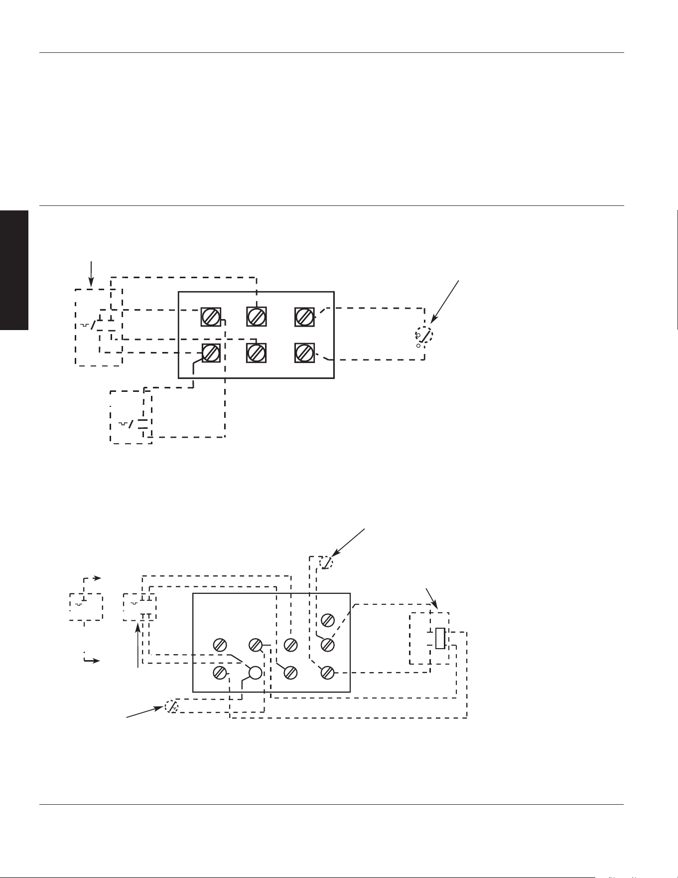
Figure 6 – Control Terminal Board (for Heaters with Contactors)
NOTES: (See Table 3, page 4,
for Electrical Accessories)
1. This style control terminal
board used with models
except 804T09, 804T10,
and 804T11.
2. Remove jumper W1 to W2
when 2-stage thermostat
is used.
3. Only one fan switch and
one thermostat accessory
may be installed in a
single heater.
4. External line voltage
thermostats should be
treated as single stage only.
T
T
MT-1
MT-2
BLACK TO W1
RED TO R
BLACK
RED
RED
BLACK
C
R W1
W2
F2
F1
G
TR
T
S
FAN RELAY
(FOR MRFS-2 AMD MHRT)
2YU33
2YU95
1-Stage
Internal Thermostat
2YU90 Heat Recovery
Thermostat Switch
(Internal)
2-Stage Internal
Thermostat
2YU82 Summer Fan
Switch Accessory
(Internal)
2YU90 Heat Recovery
Thermostat Relay
Accessory (Internal)
MT-1
MT-2
BLACK
RED
RED
BLACK
P2
H2
F1
F2
S
P1
H1
2YU95
2YU 33
Figure 5 – Control Terminal Board (for Heaters without Contactors)
NOTES: (See Table 3, page 4,
for Electrical Accessories)
1. This style control terminal board
used with models 804T09,
804T10, 804T11, and 804T18.
2. When unit is wired for single phase,
place jumper H1 to H2. If single pole
thermostat is used with single phase
unit, connect thermostat leads to
P1 and H1.
3. External line voltage thermostats
should be treated as single
stage only.
1-Stage
Internal
Thermostat
2-Stage Internal Thermostat
2YU82 Summer Fan Switch
Accessory (Internal)
Wiring Accessories
9
E
N
G
L
I
S
H
Models 804RZ6 thru 804RZ9, 804T01 thru 804T22
Dayton Operating Instructions and Parts Manual
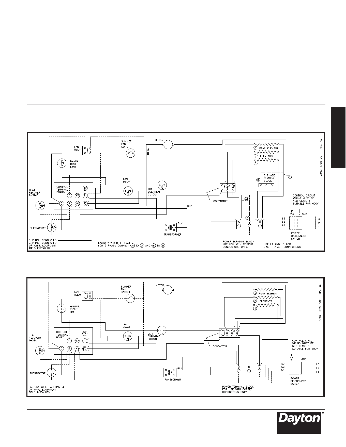
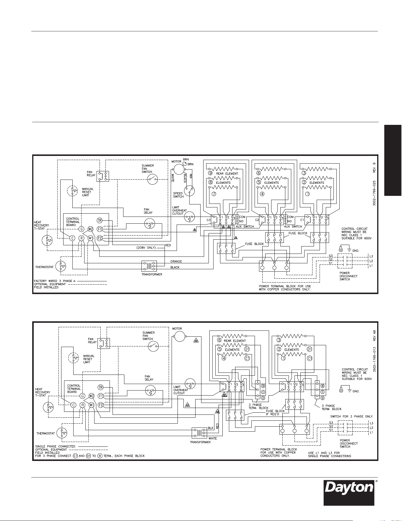
Wiring Diagrams
Diagram 2:
3 Element, Three Phase (Models 804T12, 804T19, 804T22 and 804RZ8)
Diagram 1:
3 Element, Single and Three Phase (Model 804T21)
10
E
N
G
L
I
S
H
Dayton Operating Instructions and Parts Manual
Dayton
®
Heavy-Duty Electric
Unit Heaters
804RZ6 thru 804RZ9, 804T01 thru 804T22
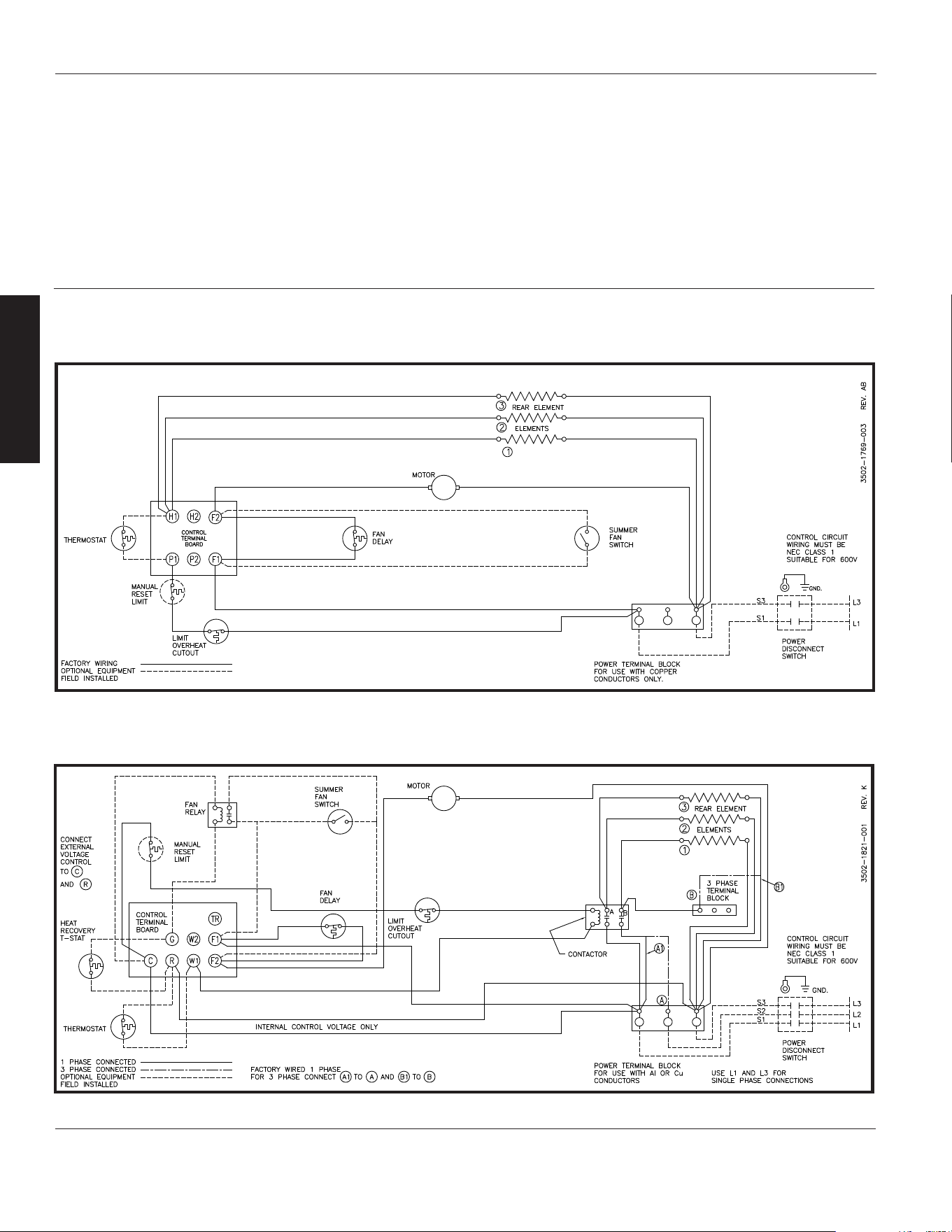
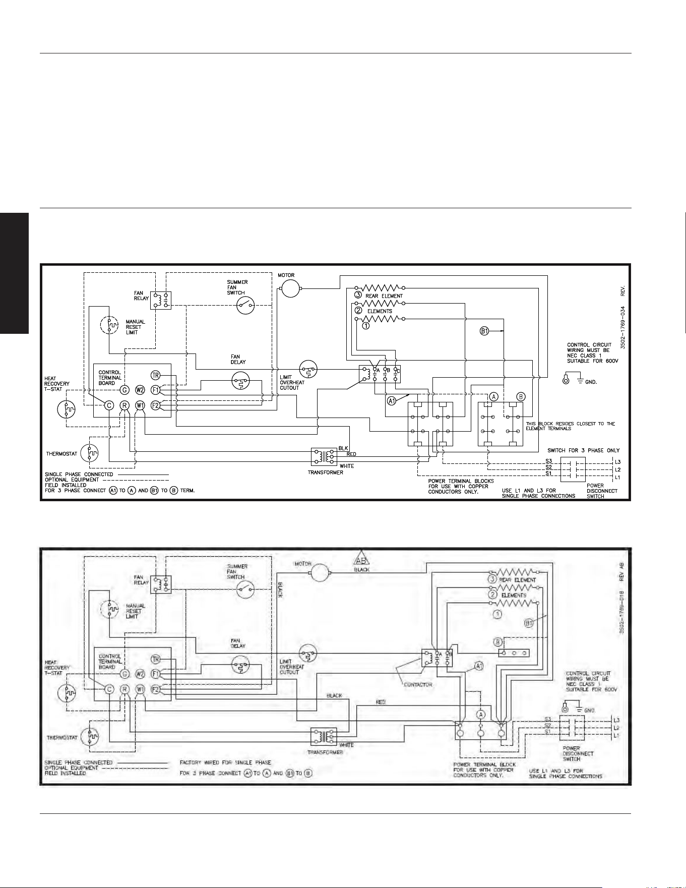
Wiring Diagrams (Continued)
Diagram 4: 3 Element, Single and Three Phase (Models 804T16, 804T17)
Diagram 3: 3 Element, Single Phase (Models 804T09, 804T10, 804T11 and 804T18)
Models 804RZ6 thru 804RZ9, 804T01 thru 804T22
Dayton Operating Instructions and Parts Manual
11
E
N
G
L
I
S
H
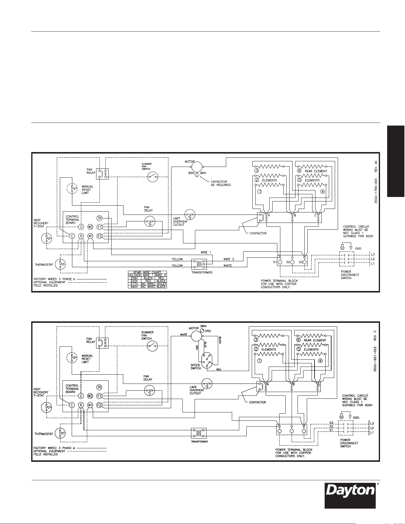
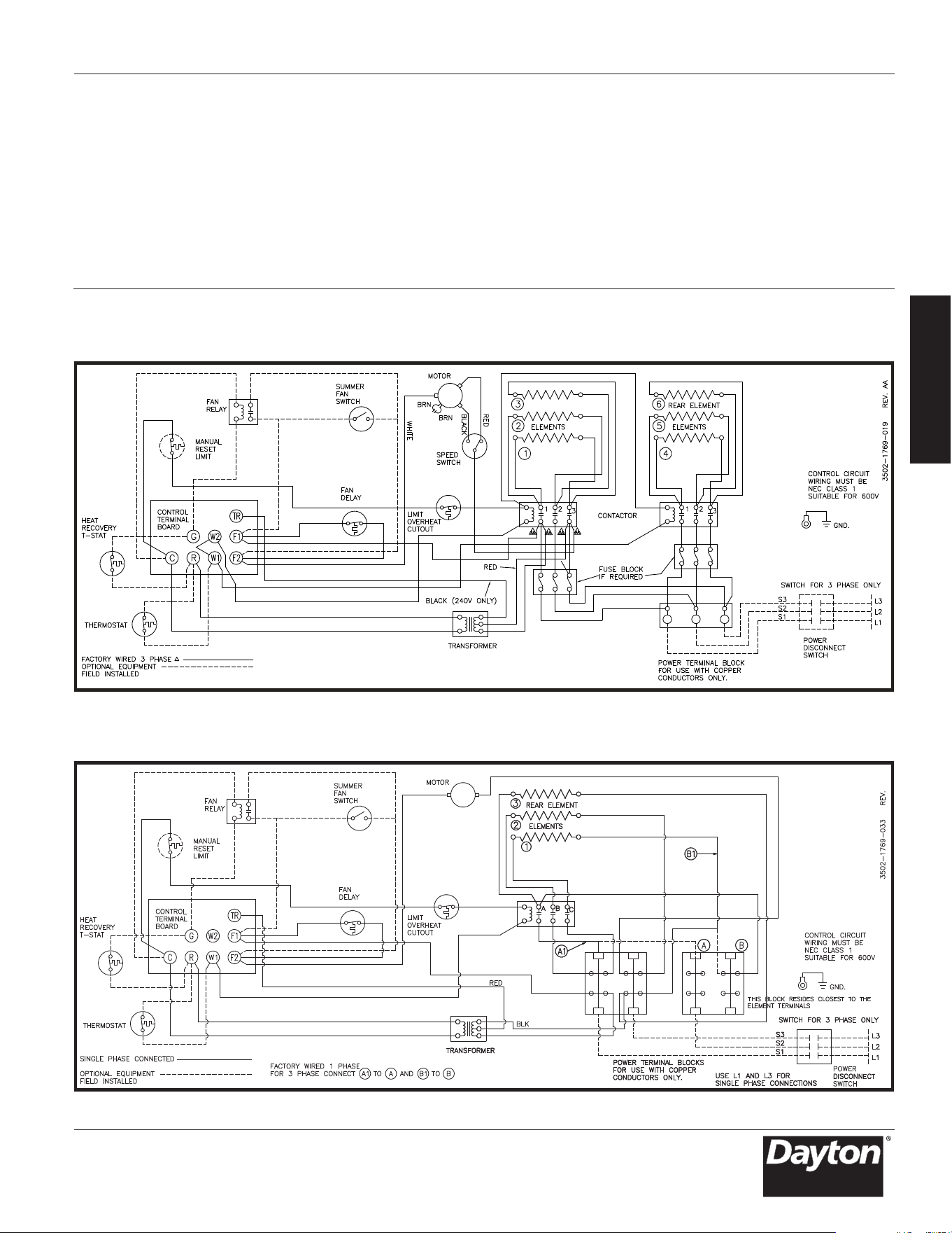
Wiring Diagrams (Continued)
Diagram 6:
6 Element, Three Phase (Model 804T05 and 804T08)
Diagram 5:
6 Element, Three Phase (Models 804T01, 804T02, 804T03 and 804T04)
12
E
N
G
L
I
S
H
Dayton Operating Instructions and Parts Manual
Dayton
®
Heavy-Duty Electric
Unit Heaters
804RZ6 thru 804RZ9, 804T01 thru 804T22
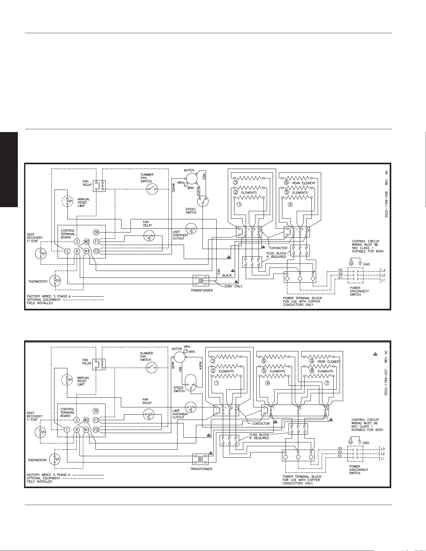
Wiring Diagrams (Continued)
Diagram 8:
9 Element, 2 Contactor, Three Phase (Model 804T13 and 804T15)
Diagram 7: 6 Element, 2 Contactor, Three Phase (Model 804T07)
13
Models 804RZ6 thru 804RZ9, 804T01 thru 804T22
Dayton Operating Instructions and Parts Manual
E
N
G
L
I
S
H
Wiring Diagrams (Continued)
Diagram 10: 6 Element, 2 Contactor, Single and Three Phase (Model 804RZ9)
Diagram 9: 9 Element, 3 Contactor, Three Phase (Model 804T14)
Wiring Diagrams (Continued)
Diagram 11: 3 Element, Single and Three Phase (Model 804RZ6)
Diagram 12: 3 Element, Single and Three Phase (Model 804T20)
Dayton Operating Instructions and Parts Manual
Dayton
®
Heavy-Duty Electric
Unit Heaters
804RZ6 thru 804RZ9, 804T01 thru 804T22
14
E
N
G
L
I
S
H
B
15
Models 804RZ6 thru 804RZ9, 804T01 thru 804T22
Dayton Operating Instructions and Parts Manual
E
N
G
L
I
S
H
Wiring Diagrams (Continued)
Diagram 14: 3 Element, Single and Three Phase (Model 804RZ7)
Diagram 13: 6 Element, 2 Contactor, Three Phase (Model 804T06)
B

E
N
G
L
I
S
H
16
Dayton Operating Instructions and Parts Manual
Dayton
®
Heavy-Duty Electric
Unit Heaters
804RZ6 thru 804RZ9, 804T01 thru 804T22
804T10 5208-0073-000 5208-0072-000 5208-0074-000 – – – 1215-0256-000 4520-0010-000
804T12 5208-0073-000 5208-0072-000 5208-0074-000 – – – 1215-0256-000 4520-0010-000
804T11 5208-0073-000 5208-0072-000 5208-0074-000 – – – 1215-0256-000 4520-0010-000
804T09 5208-0073-000 5208-0072-000 5208-0074-000 – – – 1215-0256-000 4520-0010-000
804T17 5208-0073-000 5208-0072-000 5208-0074-000 – – – 1215-0256-000 4520-0010-000
804T19 5208-0073-000 5208-0072-000 5208-0074-000 – – – 1215-0256-000 4520-0010-000
804T18 5208-0073-000 5208-0072-000 5208-0074-000 – – – 1215-0256-000 4520-0010-000
804T16 5208-0073-000 5208-0072-000 5208-0074-000 – – – 1215-0256-000 4520-0010-000
804T21 5208-0073-000 5208-0072-000 5208-0074-000 – – – 1215-0256-000 4520-0010-000
804T22 5208-0073-000 5208-0072-000 5208-0074-000 – – – 1215-0256-000 4520-0010-000
804T20 5208-0073-000 5208-0072-000 5208-0074-000 – – – 1215-0256-000 4520-0010-000
804RZ7 5208-0073-000 5208-0072-000 5208-0074-000 – – – 1215-0256-000 4520-0010-000
804RZ8 5208-0073-000 5208-0072-000 5208-0074-000 – – – 1215-0256-000 4520-0010-000
804RZ6 5208-0073-000 5208-0072-000 5208-0074-000 – – – 1215-0256-000 4520-0010-000
804T01 5208-0073-000 5208-0072-000 5208-0074-000 – – 1215-0282-000 1215-0256-000 4520-0010-000
804T02 5208-0073-000 5208-0072-000 5208-0074-000 – – 1215-0282-000 1215-0256-000 4520-0010-000
804RZ9 5208-0073-000 5208-0072-000 5208-0074-000 – – 1215-0282-000 1215-0256-000 4520-0010-000
804T03 5208-0073-000 5208-0072-000 5208-0074-000 – – 1215-0282-000 1215-0256-000 4520-0010-000
804T04 5208-0073-000 5208-0072-000 5208-0074-000 – – 1215-0282-000 1215-0256-000 4520-0010-000
804T05 5208-0073-001 5208-0072-000 5208-0074-000 5216-2053-000 1215-2258-000 – 1215-0256-000 4520-0010-000
804T07 5208-0073-001 5208-0072-000 5208-0074-000 5216-2053-000 1215-2258-000 – 1215-0256-000 4520-0010-000
804T08 5208-0073-001 5208-0072-000 5208-0074-000 5216-2053-000 1215-2258-000 – 1215-0256-000 4520-0010-000
804T06 5208-0073-001 5208-0072-000 5208-0074-000 5216-2053-000 1215-2258-000 – 1215-0256-000 4520-0010-000
804T13 5208-0073-001 5208-0072-000 5208-0074-000 5216-2053-000 1215-2258-000 1215-0282-000 1215-0256-000 4520-0010-000
804T14 5208-0073-001 5208-0072-000 5208-0074-000 5216-2053-000 1215-2258-000 1215-0282-000 1215-0256-000 4520-0010-000
804T15 5208-0073-001 5208-0072-000 5208-0074-000 5216-2053-000 1215-2258-000 1215-0282-000 1215-0256-000 4520-0010-000
804T10 – 3900-2002-006 1210-2000-000 1402-0336-002 4520-0011-000 1802-0087-000 2504-0011-003 –
804T12 5814-0003-002 3900-2005-000 1210-2000-000 1402-0336-002 4520-0011-000 1802-0087-002 2504-0011-003 –
804T11 – 3900-2002-007 1210-2000-000 1402-0336-002 4520-0011-000 1802-0087-001 2504-0011-003 –
804T09 – 3900-2002-006 1210-2000-000 1402-0336-002 4520-0011-000 1802-0087-024 2504-0011-003 –
804T17 – 3900-2002-006 1210-2000-000 1402-0336-002 4520-0011-000 1802-0087-035 2504-0011-003 –
804T19 5814-0003-002 3900-2005-000 1210-2000-000 1402-0336-002 4520-0011-000 1802-0087-005 2504-0011-003 –
804T18 – 3900-2002-007 1210-2000-000 1402-0336-002 4520-0011-000 1802-0087-004 2504-0011-003 –
804T16 – 3900-2002-006 1210-2000-000 1402-0336-002 4520-0011-000 1802-0087-034 2504-0011-003 –
804T21 5814-0003-000 3900-2014-002 1210-0090-000 1402-0339-004 4520-0011-001 1802-0087-006 2504-0013-003 –
804T22 5814-0003-002 3900-0347-005 1210-0090-000 1402-0339-004 4520-0011-001 1802-0087-008 2504-0013-003 –
804T20 5814-0003-000 3900-2014-001 1210-0090-000 1402-0339-004 4520-0011-001 1802-0087-031 2504-0013-003 –
804RZ7 5814-0003-000 3900-2014-002 1210-0090-000 1402-0339-004 4520-0011-001 1802-0087-031 2504-0013-003 –
804RZ8 5814-0003-002 3900-0347-005 1210-0090-000 1402-0339-004 4520-0011-001 1802-0087-011 2504-0013-003 –
804RZ6 5814-0003-000 3900-2014-001 1210-0090-000 1402-0339-004 4520-0011-001 1802-0087-036 2504-0013-003 –
804T01 5814-0003-000 3900-0361-000 1210-0090-001 1402-0339-004 4520-0011-001 1802-0087-012 2504-0012-003 –
804T02 5814-0003-002 3900-0361-001 1210-0090-001 1402-0339-004 4520-0011-001 1802-0087-008 2504-0012-003 –
804RZ9 5814-0003-000 3900-0361-000 1210-0090-001 1402-0339-004 4520-0011-001 1802-0087-037 2504-0012-003 –
804T03 5814-0003-000 3900-0362-000 1210-0096-000 1402-0339-004 4520-0011-001 1802-0087-037 2504-0012-003 482028000
804T04 5814-0003-002 3900-0362-001 1210-0096-000 1402-0339-004 4520-0011-001 1802-0087-011 2504-0012-003 482028000
804T05 5814-0003-000 3900-0364-000 1210-0098-000 1402-0340-004 4520-0011-002 1802-0087-018 2504-0014-003 482028000
804T07 5814-0003-002 3900-2065-000 1210-0098-000 1402-0340-004 4520-0011-002 1802-0087-017 2504-0014-003 482028000
804T08 5814-0003-002 3900-2065-000 1210-0098-000 1402-0340-004 4520-0011-002 1802-0087-019 2504-0014-003 482028000
804T06 5814-0003-000 3900-0364-000 1210-0098-000 1402-0340-004 4520-0011-002 1802-0087-028 2504-0014-003 482028000
804T13 5814-0003-002 3900-0350-001 1210-11004-000 1402-0340-005 4520-0011-002 1802-0087-021 2504-0015-003 482028000
804T14 5814-2021-001 3900-0350-000 1210-11004-000 1402-0340-005 4520-0011-002 1802-0087-022 2504-0015-003 482028000
804T15 5814-0003-002 3900-0350-001 1210-11004-000 1402-0340-005 4520-0011-002 1802-0087-023 2504-0015-003 482028000
Repair Parts List for Heavy-Duty Electric Unit Heaters
Ref. 1 Ref. 2 Ref. 3 Ref. 5 Ref. 6 Ref. 7
Element Capillary Element Ref. 4 Mounting Bracket Switch Ref. 8
Model Spring Tube Spring Retainer Spring Switch Bracket Extension Bracket Fan Delay
Ref. 17 Ref. 18 Ref. 19
Ref. 10 Ref. 11 Ref. 12 Ref. 13 Linear Limit Element Element Ref. 20
Model Transformer Motor Fan Blade Cover Protector Assy. Guard Clamp

Dayton Operating Instructions and Parts Manual
Models 804RZ6 thru 804RZ9, 804T01 thru 804T22
804T10 – – - – – 23901-00160 21424-17128
804T12 – – 5018-0004-100 2900-0030-000 – 23901-00160 21424-17128
804T11 – – – 2900-0030-000 – 23901-00160 21424-17128
804T09 – – – – – 23901-00160 21424-17128
804T17 – – – – – 23901-00160 21424-17128
804T19 – – 5018-0004-100 2900-0030-000 – 23901-00160 21424-17128
804T18 – – – 2900-0030-000 – 23901-00160 21424-17128
804T16 – – – – – 23901-00160 21424-17128
804T21 – 3504-7002-001 5018-0005-004 – – – –
804T22 – 3504-7002-001 – 2900-0030-000 – – –
804T20 – 3504-7002-001 5018-0003-000 – – – –
804RZ7 – 3504-7002-001 5018-0005-004 – – – –
804RZ8 – 3504-7002-001 – 2900-0030-000 – – –
804RZ6 – 3504-7002-001 5018-0005-004 – – – –
804T01 – 3504-7002-001 5018-0005-004 – – – –
804T02 – 3504-7002-001 5018-0004-100 2900-0030-000 – – –
804RZ9 – 3504-7002-001 5018-0005-004 – – – –
804T03 1432-0002-003 3504-7002-001 5018-0006-000 – – – –
804T04 1432-0002-003 3504-7002-001 5018-0005-004 2900-0030-000 –- –
804T05 1432-0002-003 3504-7002-001 – – 25221-60131 – –
804T07 1432-11004-000 3504-7002-001 5018-0005-004 2900-0030-000 25221-60131 – –
804T08 1432-11004-000 3504-7002-001 5018-0005-004 2900-0030-000 25221-60131 – –
804T06 1432-0002-001 3504-7002-001 5018-0006-000 – 25221-60131 – –
804T13 1432-0002-004 3504-7002-001 * 2900-0030-000 25221-60131 – –
804T14 1432-0002-004 3504-7002-001 5018-0005-004 – 25221-60131 – –
804T15 1432-0002-004 3504-7002-001 ** 2900-0030-000 25221-60131 – –
17
E
N
G
L
I
S
H
Repair Parts List for Heavy-Duty Electric Unit Heaters (Continued)
Ref. 26 Ref. 27
Ref. 21 Ref. 22 Ref. 23 Ref. 24 Ref. 25 Ground Ground
Model Capacitor Ground Lug
Relay-Contactor
Insulator Bushing Washer Screw
Ref. 29 Ref. 30 Ref. 31 Ref. 32 Ref. 33
Ref. 28 Spring Terminal Block Treminal Block, Terminal Block Fuse Ref. 34
Mo Louverdel Louver Power Control 3 Phase Block Fuse
804T10 3503-2004-106 5208-7005-001 5823-0004-000 5823-0001-000 – – –
804T12 3503-2004-106 5208-7005-001 5823-0004-000 5823-0002-000 – – –
804T11 3503-2004-106 5208-7005-001 5823-0004-000 5823-0001-000 – – –
804T09 3503-2004-106 5208-7005-001 5823-0004-000 5823-0001-000 – – –
804T17 3503-2004-106 5208-7005-001 5823-0004-000 5823-0001-000 5823-0003-000 – –
804T19 3503-2004-106 5208-7005-001 5823-0004-000 5823-0002-000 – – –
804T18 3503-2004-106 5208-7005-001 5823-0004-000 5823-0001-000 – – –
804T16 3503-2004-106 5208-7005-001 5823-0004-000 5823-0001-000 5823-0003-000 – –
804T21 3503-2004-107 5208-7005-001 5823-11012-000 5823-0002-000 – – –
804T22 3503-2004-107 5208-7005-001 5823-0004-000 5823-0002-000 – – –
804T20 3503-2004-107 5208-7005-001 5823-0004-008 5823-0002-000 5823-0003-000 – –
804RZ7 3503-2004-107 5208-7005-001 5823-11012-000 5823-0002-000 – – –
804RZ8 3503-2004-107 5208-7005-001 5823-0004-000 5823-0002-000 – – –
804RZ6 3503-2004-107 5208-7005-001 5823-11012-000 5823-0002-000 – – –
804T01 3503-2004-107 5208-7005-001 5823-0004-001 5823-0002-000 – – –
804T02 3503-2004-107 5208-7005-001 5823-0004-000 5823-0002-000 – – –
804RZ9 3503-2004-107 5208-7005-001 5823-0004-003 5823-0002-000 5823-0003-000 2025-0002-000 2019-0007-010
804T03 3503-2004-107 5208-7005-001 5823-0004-002 5823-0002-000 – – –
804T04 3503-2004-107 5208-7005-001 5823-0004-002 5823-0002-000 – – –
804T05 3503-2004-108 5208-7005-001 5823-0004-003 5823-0002-000 – 480030004 2019-7008-079
804T07 3503-2004-108 5208-7005-001 5823-0004-002 5823-0002-000 – – –
804T08 3503-2004-108 5208-7005-001 5823-0004-001 5823-0002-000 – – –
804T06 3503-2004-108 5208-7005-001 5823-0005-000 5823-0002-000 – 480030004 2019-7008-080
804T13 3503-2004-108 5208-7005-001 5823-0004-002 5823-0002-000 – – –
804T14 3503-2004-108 5208-7005-001 5823-0005-000 5823-0002-000 – 480030004 2019-7008-079
804T15 3503-2004-108 5208-7005-001 5823-0004-002 5823-0002-000 – *** ****
*Two relays are used, 40A relay 5018-0005-004 and 35A relay 5018-0004-100
**Two relays are used, 50A relay 5018-0006-000 and 35A relay 5018-0004-100
***Two fuse block are used, (30A) 600V block 2025-0001-000 and 2025-7004-000
****Two fuse styles are used, (30A) 600V 2019-7002-008 and (50A) 600V 2019-7002-012

Dayton Operating Instructions and Parts Manual
Dayton
®
Heavy-Duty Electric
Unit Heaters
804RZ6 thru 804RZ9, 804T01 thru 804T22
18
E
N
G
L
I
S
H
Symptom Possible Cause(s) Corrective Action
Thermostat calls for heat,
but heater does not function
Fan motor runs “hot”
Fan motor runs, but no heat
1. Open (blown) fuse
2. Incorrect wiring
3. Thermal cut-out open, de-energizing
heater element and control circuit
1. Dust accumulation or excessive
dirt on fan motor
2. Dirt accumulation
3. Motor needs lubrication
1. Element contact not operating
correctly
2. Element fuse blown
1. Replace fuses, check for cause (See Repair Parts
List for fuse size)
2. Check wiring connections
3. Check for the following:
Correct supply volts&phase.
Correct control wiring (heater control must be
thru thermostat control wiring section only).
Power interruption to heater during heater
operation Restriction of air around heater
1-5 minute fan purge after thermostat off
1. Clean fan motor and casing of grease and
oil accumulation
2. Clean louvers and between heating elements
3. See Maintenance
1. Check wiring for open circuit. Replace
contactor if defective
2. Replace fuses, check for cause
Troubleshooting Chart

Dayton Operating Instructions and Parts Manual
19
E
N
G
L
I
S
H
Manufactured for Dayton Electric Mfg. Co.
Lake Forest, Illinois 60045 U.S.A.
804RZ6 thru 804RZ9, 804T01 thru 804T22
Dayton Operating Instructions and Parts Manual
LIMITED WARRANTY
DAYTON ONE-YEAR LIMITED WARRANTY. DAYTON
®
HEAVY-DUTY ELECTRIC UNIT HEATERS, MODELS COVERED IN
THIS MANUAL, ARE WARRANTED BY DAYTON ELECTRIC MFG. CO. (DAYTON) TO THE ORIGINAL USER AGAINST DEFECTS
IN WORKMANSHIP OR MATERIALS UNDER NORMAL USE FOR ONE YEAR AFTER DATE OF PURCHASE. ANY PART WHICH IS
DETERMINED TO BE DEFECTIVE IN MATERIAL OR WORKMANSHIP AND RETURNED TO AN AUTHORIZED SERVICE LOCATION,
AS DAYTON
DESIGNATES, SHIPPING COSTS PREPAID, WILL BE, AS THE EXCLUSIVE REMEDY, REPAIRED OR REPLACED AT
DAYTON’S OPTION. FOR LIMITED WARRANTY CLAIM PROCEDURES, SEE “PROMPT DISPOSITION” BELOW. THIS LIMITED
WARRANTY GIVES PURCHASERS SPECIFIC LEGAL RIGHTS WHICH VARY FROM JURISDICTION TO JURISDICTION.
LIMITATION OF LIABILITY. TO THE EXTENT ALLOWABLE UNDER APPLICABLE LAW, DAYTON’S LIABILITY FOR CONSEQUENTIAL
AND INCIDENTAL DAMAGES IS EXPRESSLY DISCLAIMED. DAYTON’S LIABIL
ITY IN ALL EVENTS IS LIMITED TO AND SHALL NOT
EXCEED THE PURCHASE PRICE PAID.
WARRANTY DISCLAIMER. A DILIGENT EFFORT HAS BEEN MADE TO PROVIDE PRODUCT INFORMATION AND ILLUSTRATE
THE PRODUCTS IN THIS LITERATURE ACCURATELY; HOWEVER, SUCH INFORMATION AND ILLUSTRATIONS ARE FOR THE SOLE
PURPOSE OF IDENTIFICATION, AND DO NOT EXPRESS OR IMPLY A WARRANTY THAT THE PRODUCTS ARE MERCHANTABLE,
OR FIT FOR A PARTICULAR PURPOSE, OR THAT THE PRODUCTS WILL NECESSARILY CONFORM TO THE ILLUS
TRATIONS OR
DESCRIPTIONS. EXCEPT AS PROVIDED BELOW, NO WARRANTY OR AFFIRMATION OF FACT, EXPRESSED OR IMPLIED, OTHER
THAN AS STATED IN THE “LIMITED WARRANTY” ABOVE IS MADE OR AUTHORIZED BY DAYTON.
Technical Advice and Recommendations, Disclaimer. Notwithstanding any past practice or dealings or trade custom,
sales shall not include the furnishing of technical advice or assistance or system design. Dayton assumes no obligations or
liability on account of any unauthor
ized recommendations, opinions or advice as to the choice, installation or use of
products.
Product Suitability. Many jurisdictions have codes and regulations governing sales, construction, installation, and/or use
of products for certain purposes, which may vary from those in neighboring areas. While attempts are made to assure that
Dayton products comply with such codes, Dayton cannot guarantee compliance, and cannot be responsible for how the
product is instal
led or used. Before purchase and use ofaproduct, review the product applications, and all applicable
national and local
codes and regulations, and be
sure that the product, installation, and use will comply with them.
Certain aspects of disclaimers are not applicable to consumer products; e.g., (a) some jurisdictions do not allow the exclusion
or limitation of incidental or consequential damages, so the above limitation or exclusion may not apply to you; (b) also,
some
jurisdictions do not allow a limitation on how long an implied warranty lasts, consequently the above limitation
may not apply to you; and (c) by law, during the period of this Limited Warranty, any implied warranties of implied
merchantability or fitness for a particular purpose applicable to consumer products purchased by consumers, may not
be excluded or otherwise disclaimed.
Prompt Disposition. A good faith effort will be made for prompt correction or other adjustm
ent with respect to any
product which proves to be defective within limited warranty. For any product believed to be defective within limited
warranty, first write or call dealer from whom the product was purchased. Dealer will give additional directions. If unable to
resolve satisfactorily, write to Dayton at address below, giving dealer’s name, address, date, and number of dealer’s invoice,
and describing the nature of the defect. Title and risk of loss pass to buyer on
delivery to common carrier. If product was
damaged in transit to you, file claim with carrier.
Manufactured for Dayton Electric Mfg. Co., 100 Grainger Parkway, Lake Forest, Illinois 60045-5201 U.S.A.
Models 804RZ6 thru 804RZ9, 804T01 thru 804T22

20
Notes
804RZ6 thru 804RZ9, 804T01 thru 804T22
Dayton Operating Instructions and Parts Manual
E
N
G
L
I
S
H
804T10* 2.2/3.0 7.5/10.2 208/240 1 208/240 11.0/12.5 1/100 1600 350 800 27
804T12 3 10.2 480 3 24 3.6 1/100 1600 350 800 27
804T11* 3 10.2 277 1 277 11 1/100 1600 350 800 27
804T09* 3 10.2 208 1 208 14.5 1/100 1600 350 800 27
804T17*(**)
3.7/5.0 12.6/17.0 208/240 1-3 208/240 18.0/21.0 1/100 1600 350 800 45
804T19 5 17 480 3 24 6 1/100 1600 350 800 45
804T18* 5 17 277 1 277 18 1/100 1600 350 800 45
804T16*(**)
5 17 208 1-3 208 24.0/13.9 1/100 1600 350 800 45
804T21 5.6/7.5 19.1/25.6 208/240 1-3 24 27.0/31.3 1/30 1600 650 970 37
804T22 7.5 25.6 480 3 24 9 1/30 1600 650 970 37
804T20 7.5 25.6 208 1-3 24 36/20.8 1/30 1600 650 970 37
804RZ7 7.5/10.0 25.6/34.1 208/240 1-3 24 36.0/42.0 1/30 1600 650 970 49
804RZ8 10 34.1 480 3 24 12 1/30 1600 650 970 49
804RZ6 10 34.1 208 1-3 24 48.0/27.7 1/30 1600 650 970 49
804T01 11.2/15.0 38.2/51.2 208/240 3 24 31.3/36.1 1/20 1530 910 1640 52
804T02 15 51.2 480 3 24 18 1/20 1530 910 1640 52
804RZ9 15 51.2 208 1-3 24 72.0/41.6 1/20 1530 910 1640 52
804T03 15.0/20.0 51.2/68.2 208/240 3 24 41.2/48.0 1/10 1500 1320 2060 48
804T04 20 68.2 480 3 24 24 1/10 1500 1320 2060 48
804T05 25 85.2 480 3 24 30 1/4 1600/1375 2100/1800 2100/2030 38/44 50
804T07 22.5/30.0 76.7/102.3 208/240 3 24 63.0/72.3 1/4 1600/1375 2100/1800 2100/2030 45/53 50
804T08 30 102.3 480 3 24 36
804T06 30 102.3 208 3 24 84
804T13 40 136.4 480 3 24 48
804T14 37.5/50.0 127.3/170.5 208/240 3 24 104.2/120.0 1/2 1525/1420 3000/2600 3260/2900 53/61 60
804T15 50 170.5 480 3 24 60.2 1/2 1525/1420 3000/2600 3260/2900 53/61 60
Unidades de Calefacción Eléctricas
para Servicio Pesado Dayton
®
12
12
12
12
12
12
12
12
18
18
18
18
18
18
35
35
35
41
41
1/4 1600/1375 2100/1800 2100/2030 45/53 50
1/4 1600/1375 2100/1800 2100/2030 45/53 50
1/2 1525/1420 3000/2600 3260/2900 42//49 60
Manual de Instrucciones de Operación y Lista de Partes
804RZ6 a 804RZ9, 804T01 a 804T22
Por favor lea y guarde estas instrucciones. Léalas cuidadosamente antes de tratar de montar, instalar,
operar o dar mantenimiento al producto aquí descrito. Protéjase usted mismo y a los demás observando toda la información de seguridad.
¡
El no
cumplir con las instrucciones puede ocasionar daños, tanto personales como a la propiedad! Guarde estas instrucciones para referencia en el futuro.
E
S
P
A
Ñ
O
L
CARACTERISTICAS
• Las unidades de 5 a 15 kW se pueden
convertir en el campo de una fase a
tres fases
• Un circuito de control de bajo voltaje
de 24 voltios es estándar, excepto
en las unidades de 3 or 5 kW, 208 V,
240/208 V, or 277 V, las cuales tienen
un control de voltaje de línea
• Motores totalmente cerrados de
servicio pesado
• Elemento de calefacción revestido con
acero, cubierto con hoja de cobre,
con aletas de aluminio
• Su diseño avanzado de rejilla de
entrada permite que el aire frío fluya
a través del elemento de calefacción
para lograr una operación más
eficiente
• Protector térmico lineal de reposición
automática
• Salida venturi con aspas de ventilador
grandes equilibradas dinámicamente
• Alojamiento de acero moldeado de
calibre grueso
• Hay soportes horizontales y verticales
opcionales disponibles
Figura 1
(*) Estos modelos están cableados para control de voltaje de línea directa.
Capacidad Volt. Ca- Voltaje Amp. Motor del MCH MPS Aumento Expul-
Nominal BTU/Hr lentador/ de por Ventilador en la en la Temp. sión Aire
Modelo de kW (x1000) Motor Fase Control Fase CF RPM Salida Salida Aire (°C) (Horiz.)
Descripción
Los Calentadores Eléctricos para Servicio Pesado Dayton están diseñados para
uso continuo o intermitente en fábricas, almacenes, edificios públicos, salas de
existencias, estaciones de servicio, cualquier área grande o expuesta, o adiciones.
Se pueden instalar para uso en aplicaciones de flujo descendente u horizontal.
Especificaciones
Formulario
Impreso en EE. UU.
09663
04/2023
5200-11259-000
ISS 1.0-003
ECR-02717
(**) Debe usar un termostato de dos etapas en la operación de 3Ø.
2-Sp
E
S
P
A
Ñ
O
L
Desempaque
Extraiga el calentador de la caja e
inspecciónelo para ver si está dañado.
Si parece estar dañado, devuélvalo
inmediatamente.
Revise el contenido de la caja para
asegurarse que ésta contiene una
unidad de calefacción.
INSTRUCCIONES
IMPORTANTES
Cuando se utilicen
aparatos eléctricos,
siempre deberán seguirse las medidas
de precaución básicas para reducir el
riesgo de incendio, choque eléctrico
y lesiones personales, incluyendo
las siguientes:
1. Lea todas las instrucciones antes de
instalar o utilizar este calentador.
2. Este calentador es un producto
comercial/industrial que no ha sido
diseñado para uso en un entorno
residencial.
3. Este calentador está caliente cuando
se utiliza. Para evitar quemaduras, no
permita que la piel expuesta toque
las superficies calientes. Mantenga los
materiales combustibles, tales como
muebles, almohadas, ropas de cama,
papeles, vestimentas, etc. y cortinas
al menos a 0.9 m
etros (3 pies) de
distancia del frente del calentador.
4. Se requiere una precaución extrema
cuando cualquier calentador es
utilizado por o cerca de los niños o
personas minusválidas, y siempre que
se deje el calentador funcionando y
desatendido.
5. Este calentador tiene en su interior
piezas calientes y productoras de
arcos eléctricos o chispas eléctricas.
No está aprobado para uso en
atmósferas peligrosas u otras
atmósferas combustibles donde se
utilicen o almacenen
líquidos, gases
o vapores inflamables. No cumplir
con lo aquí descrito puede ocasionar
explosiones o incendios.
6.
No utilice ningún calentador que
se haya malogrado. Desconecte la
energía eléctrica en el panel principal
de servicio y permita que un
electricista de buena reputación lo
inspeccione antes de volverlo a usar.
7. No lo utilice en exteriores.
8. Para desconectar el calentador,
ponga los controles en apagado,
y desconecte la alimentación
eléctrica para el calentador en
el panel principal de servicio.
9. No inserte ni permita que objetos
extraños entren en ninguna abertura
de ventilación o escape, ya que esto
podría causar un choque eléctrico,
incendio o daños al calentador.
10. Para evitar un posible incendio,
no bloquee de ninguna manera
la entrada o salida de aire.
11. Utilice este calentador sólo como se
describe en este manual. Cualquier
otro uso no recomendado por el
fabricante podría causar incendio,
choque eléctrico o le
siones a las
personas.
12. Este calentador no ha sido diseñado
para uso en ambientes especiales.
No lo utilice en lugares húmedos o
mojados tales como lugares marinos
o invernaderos o en áreas donde
haya agentes químicos o corrosivos
presentes.
13. Cuando instale la unidad, consulte
la sección INSTRUCCIONES DE
INSTALACION para ver advertencias
y precauciones adicionales.
14. Para un funcionamiento seguro y
eficaz, y para extender la vida útil
de su calentador, mantenga
limpio
su calentador. Consulte la sección
INSTRUCCIONES DE MANTENIMIENTO.
Instrucciones
de Instalación
Para evitar un
posible incendio,
posibles lesiones personales o posible
daño al calentador, cumpla con lo
siguiente:
1. Desconecte toda la alimentación
eléctrica suministrada para el
calentador en el panel principal
de servicio antes de intentar hacer
cualquier trabajo de cableado o
mantenimiento.
AVISO IMPORTANTE: Una persona
calificada debe instalar el cal
entador.
2. Todos los procedimientos y conexiones
de cableado deberán cumplir con los
códigos eléctricos nacionales y locales
que tengan jurisdicción en el lugar
de instalación del calentador, y
éste deberá conectarse a tierra.
3. Verifique que el voltaje de
alimentación suministrado al
calentador coincida con los valores
de capacidad mostrados en la placa
de identificación del calentador.
Energizar el
calentador
con un voltaje mayor que el voltaje
impreso en la placa de identificación
del calentador dañará el calentador y
anulará la garantía del mismo, y podría
causar un incendio.
4. Para disminuir el riesgo de incendio,
no almacene ni utilice gasolina u
otros líquidos o vapores inflamables
cerca del calentador.
5. La estructura de montaje en pared o
cielo raso y los dispositivos de anclaje
deberán ser lo suficientemente
fuertes como para soportar el peso
combinando del calentador y el
soporte de montaje.
6. Todos los termostatos inc
orporados:
Si se utiliza el calentador para
impedir que las tuberías o líquidos se
congelen, y se ajusta el termostato a
una temperatura por debajo de 7 °C
(45 °F), el ventilador debe funcionar
continuamente.
7. El calentador debe montarse a no
menos de 2134 mm (7 pies) sobre
el piso para evitar todo contacto
accidental con las aspas del
ventilador, lo cual podría causar
lesiones.
Unidades de Calefacción Eléctricas
para Servicio Pesado Dayton
®
804RZ6 a 804RZ9, 804T01 a 804T22
Manual de Instrucciones de Operación y Lista de Partes Dayton
3-Sp
Instrucciones
de Instalación
(Continuación)
8. Mantenga al menos 1.5 m (5 pies) de
espacio libre en frente del calentador.
Consulte la Tabla 1 para ver los
requisitos de espacio libre lateral,
superior y posterior.
9. No monte termostatos de tipo de
mercurio directamente en la unidad.
La vibración podría causar que el
calentador funcione mal.
UBICACION DEL CALENTADOR
1. Disponga las unidades para que sus
corrientes de aire de descarga estén
sujetas a un mínimo de interfer
encia
por parte de las columna
s y
particiones.
2. Dirija la corriente de aire lejos de los
ocupantes que estén en la habitación,
en una calefacción de comodidad.
3. Las corrientes deberán rozar las
paredes expuestas sin soplar
directamente hacia ellas.
4. Dirija la corriente de aire a lo largo
del lado de viento de una habitación
cuando instale en un edificio
expuesto a un viento predominante.
5. Si utiliza un termostato remoto, sitúe
el termostato a aproximadamente
1.5 m (5 p
ies) sobre el piso en los
postes o paredes de par
tición
interiores y alejado de las corrientes
de aire frío, fuentes de calor
interiores,yde las corrientes de
aire de descarga.
6. Las habitaciones grandes requieren
instalaciones de múltiples unidades.
Disponga las unidades para
proporcionar una circulación de
aire perimetral donde cada unidad
apoya la corriente de aire de otra.
MONTAJE
EN GENERAL (Consulte la Tabla 3, en
la página 4, para ver los Accesorios
de Montaje)
1.
Sitúe el calentador de manera que
se pueda abrir la puerta de acceso
para dar acceso al compartimiento de
control y cableado. Si se va a montar
el calentador con la puerta de acceso
orientada hacia una pared, el
calentador debe montarse suficiente-
mente lejos de la pared para poder
abrir completamente la puerta de
acceso (aproximadamente igual a
la profundidad del calentador).
Consulte la Tabla 1.
Modelos 804RZ6 a 804RZ9, 804T01 a 804T22
Manual de Instrucciones de Operación y Lista de Partes Dayton
E
S
P
A
Ñ
O
L
3y5 kW Horiz. 50.8 (2) 152.4 (6) 228.6 (9) 2YV16
Vert. 152.4 (6) 457.2 (18) 457.2 (18) 2YU84
7.5 a 10 kW Horiz. 152.4 (6) 152.4 (6) 330.2 (13) 2YV16
Vert. 152.4 (6) 609.6 (24) 609.6 (24) 2YU84
15 a 20 kW Horiz. 152.4 (6) 228.6 (9) 317.5 (12
1
/2) 2YV17
Vert. 152.4 (6) 609.6 (24) 609.6 (24) 2YU84
25 a 50 kW Horiz. 406.4 (16) 304.8 (12) 470.0 (18
1
/2) 2YU91 y 92
Vert. 304.8 (12) 914.4 (36) 914.4 (36) 2YU85
Tabla1– Espacios Libres de Pared y Cielo Raso, mm (pulg.) / Soportes de Montaje
Soportes de
Pared Pared Montaje
Unidad Descarga Cielo Raso Lateral Posterior Opcionales
3 - 5kW 5/16”-18 154 152.4 103.2 19.1 152.4 247.7 50.8 106.4
7.5 a 10 5/16-18 154 225.4 130.2 19.1 225.4 371.5 50.8 130.2
15 a 20 5/16-18 288.9 225.4 130.2 19.1 225.4 377.8 50.8 130.2
25 a 30 3/8-16 268.3 368.3 157.2 15.9 368.
Figura 2. Montaje y Espaciamiento de Descarga Horizontal
TECHO
PARED POSTERIOR
P
A
R
E
D
P
O
S
T
E
R
I
O
R
P
A
R
E
D
L
A
T
E
R
A
L
VARILLA DE
MONTAJE
TUERCA
DE BLOQUEO
CALENTADOR DE
LA UNIDAD
AGUJERO DE
MONTAJE
ROSCADO
B
A
D
C
(VISTA SUPERIOR)
Figura 3. Montaje de descarga vertical y espaciado entre varillas
PUERTA DE
ACCESO
AGUJERO DE
MONTAJE
ROSCADO
ESPACIO IGUAL AL ANCHO DEL CALENTADOR
PARA PERMITIR LA APERTURA COMPLETA DE
LA PUERTA DE ACCESO
E
H
F
G
(VISTA SUPERIOR)
Rosca tipo varilla (Figura 2) (Figura 3)
Tipo Horizontal Vertical
Unidad Varilla A B C D E F G H
TECHO
TUERCA
DE BLOQUEO
P
A
R
E
D
P
O
S
T
E
R
I
O
R
P
A
R
E
D
L
A
T
E
R
A
L
PARED POSTERIOR
VARILLA DE
MONTAJE (4)

4-Sp
E
S
P
A
Ñ
O
L
Instrucciones
de Instalación
(Continuación)
2. El calentador se puede montar para
proveer descarga vertical u horizontal
mediante el uso de varillas roscadas.
Consulte la Tabla 2.
3. Unos soportes de montaje opcionales
permiten el giro horizontal del
calentador.
4. Las rejillas se pueden colocar
para dirigir el aire caliente en la
dirección deseada. Para una descarga
horizontal, las rejillas deben dirigir
el aire ya sea directamente hacia
delante o hacia abaj
o.
MONTAJE DE LAS VARILLAS
DESCARGA HORI
ZONTAL
1. Instale cuatro varillas de montaje
roscadas en los agujeros roscados y
fíjelas en posición usando tuercas
de seguridad. (Consulte la Tabla 2).
2. Instale firmemente las cuatro varillas
de montaje en el cielo raso. (Consulte
la Tabla 1 para ver los espacios libres
de paredycielo raso, y la Tabla 2
para ver la separación de las varillas
de montaje).
DESCARGA VERTICAL
1. Extraiga los pernos de los agujeros
roscados en la parte po
sterior de
los calentadores.
2. Instale cuatro varillas de montaje
roscadas
en los agujeros roscados y
fíjelas en posición usando tuercas
de seguridad.
3. Instale firmemente las cuatro varillas
de montaje en el cielo raso. (Consulte
la Tabla 1 para ver los espacios
libres de pared y cielo raso, y la
Tabla 2 para ver las dimensiones de
separación de las varillas de montaje).
Unidades de Calefacción Eléctricas
para Servicio Pesado Dayton
®
Manual de Instrucciones de Operación y Lista de Partes Dayton
2YU34 Juego de difusor radial Sólo se usa en los calentadores de 7.5 a 20 kW
(804T01 a 804T04, 804T20 a 804T22, 804RZ6 a 804RZ9)
2YU83 Juego de soporte de montaje en cielo raso Sólo se usa en los calentadores de
para descarga vertical 3 y 5 kW (804T09 a 804T12, 804T16 a 804T19
2YU84 Juego de soporte de montaje en cielo raso Sólo se usa en los calentadores de 7.5 a 20 kW
para descarga vertical (804T01 a 804T04, 804T20 a 804T22, 804RZ6 a 804RZ9)
2YU85 Juego de soporte de montaje en cielo raso Sólo se usa en los calentadores de 25 a 50 kW
para descarga vertical (804T06 a 804T08, 804T14, 804T15, 804T05 y 804T13)
2YV16 Juego de soporte universal para montaje en Sólo se usa en los calentadores de 3 a 10 kW
pared y cielo raso (804T09 a 804T12, 804T16 a 804T22, 804RZ6 a 804RZ8)
2YV17 Juego de soporte universal para montaje en Sólo se usa en los calentadores de
pared y cielo raso 15 y 20 kW (804T01 a 804T04, 804RZ9)
2YU91 Juego de soporte universal para montaje en Sólo se usa en los calentadores de
pared y cielo raso 25 y 30 kW (804T05 a 804T08)
2YU92 Juego de soporte universal para montaje en Sólo se usa en los calentadores de
pared y cielo raso 40 y 50 kW (804T13 a 804T15)
2YU33 Termostato interior unipolar Todas las unidades de calefacción Dayton
Gama de temp. 4.4 °Ca29.4 °C (40 °Fa85 °F)
2YU95 Termostato interior de dos etapas Sólo se puede usar en los modelos 804T06, 804T07,
Gama de temp. 4.4 °Ca29.4 °C (40 °Fa85 °F) 804T09, 804T10, 804T11, 804T14, 804T15
2YU82 Interruptor interior del ventilador para el verano Todas las unidades de calefacción Dayton
2YU90 Termostato interior de recuperación térmica con relé Sólo se pueda usar en los modelos 804T09, 804T10,
(bobina de 24 V – unipolar, normalmente abierta) 804T11, 804T18
2YU93 Interruptor tripolar de desconexión de la Sólo se usa en los modelos 804T02, 804T04, 804T09,
alimentación de 25 amperios con capacidad 804T10, 804T11, 804T12, 804T16, 804T17, 804T18,
804T19, 804T22, 804RZ8
nominal de 25 amperios resistivos a 600 voltios
2YU94 Interruptor tripolar de desconexión de la Sólo se usa en los modelos 804RZ9 (cuando e
alimentación de 60 amperios con capacidad cableado para tres fases), 804T01, 804T04, 804T05,
nominal de 60 amperios resistivos a 600 voltios 804T08, 804T13, 804T21 y 804RZ7
Accesorio
Eléctrico Descripción Notas de Compatibilidad del Producto
Accesorio
Mecánico Descripción Notas de Compatibilidad del Producto
Tabla 3–Accesorios Opcionales
804RZ6 a 804RZ9, 804T01 a 804T22
5-Sp
Instrucciones
de Instalación
(Continuación)
CABLEADO
CIRCUITO DERIVADO (ALIMENTACION)
1. Conecte el calentador únicamente
en un circuito que tenga el voltaje,
amperaje y frecuencia especificados
en la placa de identificación.
2. Se debe utilizar el tamaño correcto
de conductor para conducir el
amperaje de acuerdo con el Código
Eléctrico Nacional estadounidense en
los cableados realizados en el campo.
3. La puerta de acceso tiene bisagras.
Hay uno, o bien dos tornil
los
accesibles desde la parte inferior que
se deben extraer para tener acceso.
4. Se suministra un agujero ciego en
la parte posterior del calentador,
cerca de la placa de terminales de
alimentación. El agujero ciego para la
placa de terminales de control es para
un tamaño de conducto de 12.7 mm
(1/2 pulg.). El agujero ciego para el
bloque de terminales de alimentación
tiene múltiples diámetros. Utilice el
diámetro que corresponde con el
tamaño de conducto necesario.
5. Se pr
oporciona una terminal a tierra
cerca de la placa de terminales de
alimentación. El cable de conexión
a tierra debe conectarse antes de
llevar a cabo otras conexiones.
6. La placa de terminales de alimenta-
ción está equipada con terminales
de caja del tamaño adecuado para
aceptar el conductor de suministro de
energía eléctrica del tamaño correcto.
El alambre con capacidad de 600 V y
60 °C es adecuado para el circuito
derivado del calentador. El alambre de
aluminio, o bien de c
obre es adecuado
para conectarlo a la terminal de
caja de la placa de terminales de
alimentación. Se recomienda usar
un alambre de cobre.
diagrama antes de hacer cualesquiera
conexiones en el campo.
7. Cada calentador tiene un diagrama
eléctrico pegado en el lado interior
de la puerta de acceso. Consulte este
AVISO IMPORTANTE: Par de torsión
de instalación de las lengüetas
atornillables – durante el transporte es
posible que las conexiones de lengüeta
atornillable puedan
aflojarse. Una vez
instalado, antes de encender el calefactor,
verifique que todos los tornillos estén
ajustados con los valores de ajuste
mínimos recomendados en el rótulo
adjunto a la unidad.
8. Se pueden utilizar conexiones
monofásicas o trifásicas con los
modelos de calentandor 804T16,
804T17, 804T20, 804T21, 804RZ6,
804RZ7, y 804RZ9. Estas unidades
vienen cableadas de la fábrica para
funcionamiento monofásico. Si estos
calentadores se vanautilizar con
alimentación trifásica, reconecte los
conductores según se indica en el
diagrama eléctrico que está pegado
en el calentador.
a. Se puede obtener información
adicional viendo las ilustracio
nes
de cableado en las Figuras 4a a 4c
y siguiendo las instrucciones bajo el
apartado de “Cableado de Control”.
Modelos
804RZ6 a 804RZ9, 804T01 a 804T22
Manual de Instrucciones de Operación y Lista de Partes Dayton
E
S
P
A
Ñ
O
L
Figura 4a – Conexiones Eléctricas para las Alimentaciones MonofásicayTrifásica
(804T16, 804T17, 804T20, 804T21)
A
B
Frente del
calentador
Conductor “A1”
Bloque trifásico
Elementos
Conductor “B1”
Bloque de terminales
de alimentación
Contactor (o P2)
A los elementos
A
B
Frente del
calentador
Elementos
Conductor “A1”
Bloque trifásico
Conductor “B1”
Bloque de terminales
de alimentación
Contactor (o P2)
A los elementos
Cableado en el campo para
alimentación trifásica
Cablead
Alternativa trifásicaAlternativa monofásica
o en la fábrica para
alimentación monofásica
Figura
4b – Conexiones de cableado para alimentación monofásica y trifásica
(
804RZ6 y 804RZ7)
b. En los Modelos 804T16, 804T17,
804T20, 804T21, 804RZ6 y 804RZ7
(Figuras 4a y 4c), mueva solamente
los
dos conductores marcados como
“A1” y “B1”; no mueva ni cambie
ningún otro conductor. El conduc-
tor del elemento marcado como
“B1” que viene conectado de la
fábrica en el bloque de terminales
de alimentación (el terminal que
está más cerca de los elementos)
debe moverse a la terminal “B”
(3) ELEMENTOS
CONTACTOR
BLOQUE DE TERMINALES
DE POTENCIA
BLOQUE
TRIFÁSICA
L2
A1
L3
L1
B1
(3) ELEMENTOS
A
B
1
2
3
(3) ELEMENTOS
(3) ELEMENTOS
CONTACTOR
BLOQUE DE TERMINALES
DE POTENCIA
A
L2
L3
A1
C
B
A
L1
B1
B
1
2
3
1
2
3
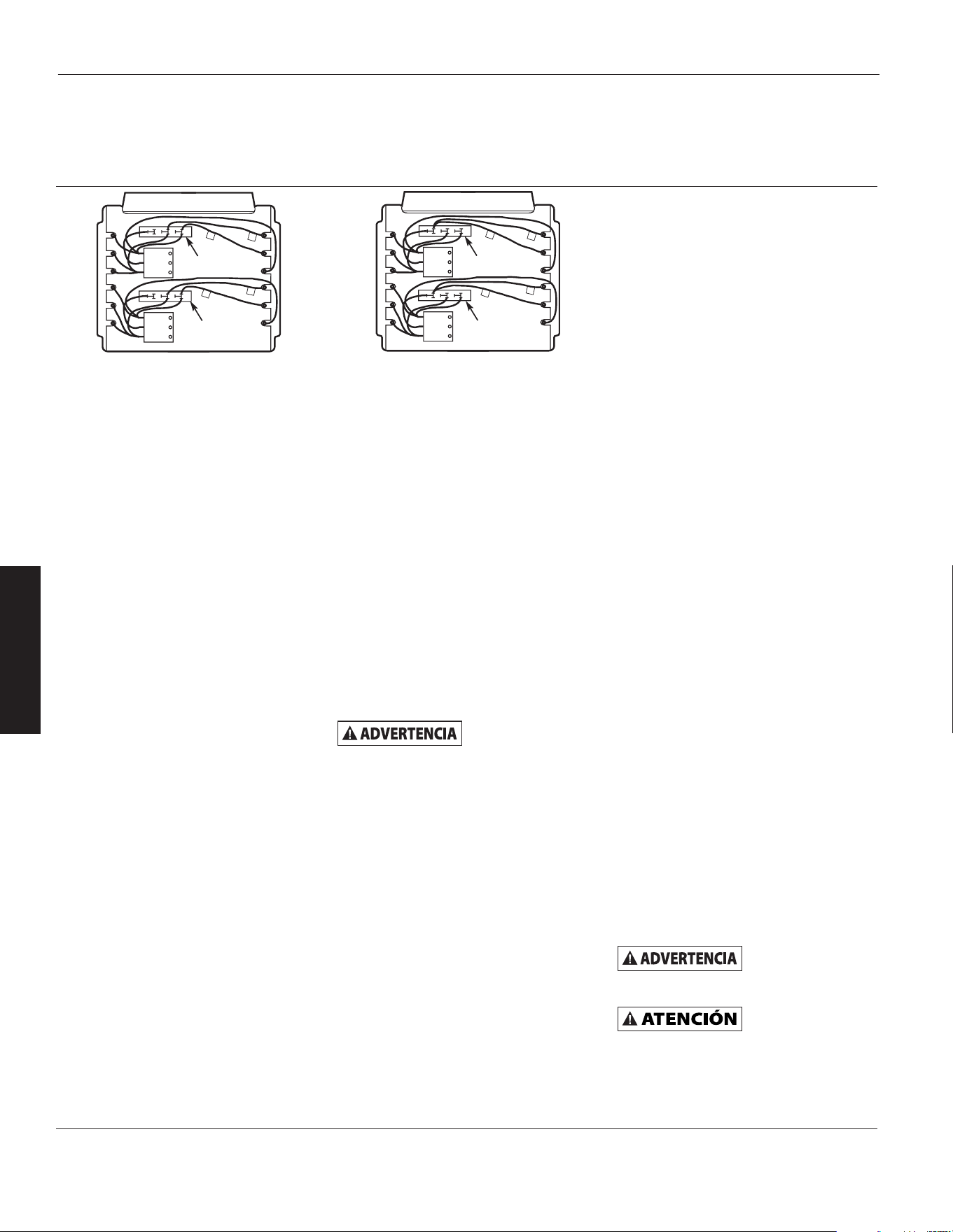
Figura 4c – Conexiones Eléctricas para las Alimentaciones Monofásica y
Trifásica (804RZ9)
B
C
1
D
1
D
1
C
1
C
D
B
C
D
Bloque trifásico
Bloque trifásico
B
C
1
D
1
D
1
C
1
C
D
B
C
D
Bloque trifásico
Bloque trifásico
Cableado en el campo para
alimentación trifásica
Cableado en la fábrica para
alimentación monofásica
6-Sp
E
S
P
A
Ñ
O
L
Instrucciones
de Instalación
(Continuación)
en el bloque de terminales
d. El Modelo 804RZ9 (Figura 4b)
tiene dos bloques de terminales
trifásicos situados adyacentes
a los relés
(contactores). Mueva
solamente los dos conductores
que están marcados como “C1”
y “D1” en cada uno d
e estos dos
bloques de terminales trifásicos
a la terminal “B”. No mueva ni
cambie ningún otro conductor.
9. Los Accesorios Eléctricos, ya sean
juegos u opciones instaladas en la
fábrica, se muestran conectados
mediant
e una línea discontinua
en el diagrama de cableado del
calentador.
1
0. CALENTADOR DE 208/240 VOLTIOS.
Los calentadores vienen cableados
de fábrica para uso con 240 voltios.
Si se va a conectar el calentador a
un suministro eléctrico de 208 V,
se tendrán que in
tercambiar los
conductores del transformador.
Para el modelo 804T14, intercambie
los conductores primarios NARANJA
y ROJO. El conductor de color
negro es el conductor COMUN
para el transformador de 50 VA
suministrado con este modelo. Para
los otros modelos, intercambie los
conductores primarios NEGRO y
ROJO. El conductor de color BLANCO
es el conductor COMUN para el
trans
formador de control de 40 VA
suministrado con estos calentadores.
Siempre consulte el diagrama de
c
ableado que está en la cubierta
del calentador antes de hacer la
reconexión de los conductores
primarios del transformador.
CABLEADO DE CONTROL
Hay voltaje de
línea presente en
algunas de las terminales de la placa
de terminales de control. Siempre
desconecte la alimentación para el
calentador antes de hacer cualesquiera
conexiones en la placa de control para
evitar el peligro de electrocución.
1. Utilice un conductor aislado NEC
Clase 1, de 600 voltios como mínimo
para todo el cableado del circuito
de control.
2. Utilice una terminal de horquilla de
tipo engarzable en los extremos de
los conductores que se conectan en
la placa de terminales de control si
se va a hacer más de una conexión
bajo la terminal de tornillo.
3. En las unidades que no tienen un
contactor interior (3 kW), consulte
la Figura 5, en la página 8, para
ver el diagrama de cableado.
AVISO: El cableado del circuito
de control y termostato deberá ser
adecuado para soportar la carga pl
ena
del calentador (por ejemplo, el 804T09
tiene una capacidad nominal de
24 amperios).
4. En las unidades que tienen un
contactor interior (unidades con
capacidad de 5 kW o más alto),
consulte la Figura 6, en la página 8,
para ver el diagrama de cableado. El
tamaño de los conductores de control
no deberá ser inferior a 18 AWG.
Instrucciones
de Operación
1. Se debe instalar correctamente el
calentador antes de utilizarlo.
2. Conecte el suministro eléctrico del
calentador en el panel de servicio
principal.
3. Donde aplique, refiérase a las
instrucciones del accesorio de control
referente a la operación correcta de
cualquier control o accesorio que
se utilicen con el calentador.
COMO REPONER EL CONTROL DE
SEGURIDAD DE SOBRETEMPERA-
TURA (OPCION INSTALADA EN
FABRICA UNICAMENTE)
El interruptor limitador está situado
adentro en la parte posterior del
calentador. En los modelos de 3 kW
y 5 kW, el acceso al botón de reposición
está en el lado derecho (c
uando se
está mirando la parte posterior del
calentador); en todos los otros modelos
el acceso está cerca de la parte superior
posterior del calentador.
El límite de reposición manual está
conectado en serie con el protector
(límite) de reciclaje automático. El límite
de reposición manual no se repondrá
sino hasta que el calentador se haya
enfriado y se haya oprimido el botón
.
No altere ni se
desvíe de ninguno
de los límites de seguridad que están
dentro del calentador.
No trate de
continuar el
uso del calentador si el control de
seguridad se activa repetidamente
después de reponerlo. Si continúa
el uso del calentador, podría dañar
permanentemente éste o crear un
peligro de seguridad o incendio.
Unidades de Calefacción Eléctricas
para Servicio Pesado Dayton
®
804RZ6 a 804RZ9, 804T01 a 804T22
Manual de Instrucciones de Operación y Lista de Partes Dayton
trifásica.
c. Para 804RZ6 y 804RZ7, el cable
“A1” se debe mover del bloque
de terminales de alimentación al
terminal “A” del bloque de
terminales trifásico. Para 804T16,
804T17, 804T20, y 804T21.
“A1” debe moverse al terminal
“A” (central) del bloque de
terminales de alimentación.
7-Sp
Modelos 804RZ6 a 804RZ9, 804T01 a 804T22
Manual de Instrucciones de Operación y Lista de Partes Dayton
E
S
P
A
Ñ
O
L
Instrucciones de
Mantenimiento
Es importante mantener limpio este
calentador. Su calentador le brindará
años de servicio y comodidad con sólo
un cuidado mínimo. Para garantizar
un funcionamiento eficaz, siga las
instrucciones sencillas que se dan
a continuación.
Todos los trabajos
de servicio más allá
de una simple limpieza que requiera
desmontaje deben ser realizados por
un personal de servicio calificado.
Para disminuir
el riesgo de
incendio y choque eléctrico o lesiones,
desconecte toda la alimentación
eléctrica suministrada para el
calentador en el panel principal de
servicio y verifique que el elemento se
haya enfriado antes de hacer cualquier
trabajo de servicio o mantenimiento.
INSTRUCCIONES DE LIMPIEZA
DEL USUARIO
1. Después de que el calentador
se haya enfriado, se puede usar
una aspiradora equipada con una
escobilla para eliminar el polvo y las
pelusas de las superficies exteriores
del calentador, incluyendo las
abert
uras de la rejilla.
2. Con un trapo húmedo, limpie el
polvo y las pelusas de la rejilla y
de las superficies exteriores.
3. Reconecte el suministro eléctrico
para el calentador y verifique que
éste funcione correctamente.
INSTRUCCIONES DE LIMPIEZA
DE MANTENIMIENTO
(Para ser realizada por un personal
de servicio calificado)
Al menos una vez anualmente, una
persona calificada debe limpiar y darle
servicio al calentador para garantizar
el funcionamiento seguro y eficaz de
l
mismo. Esto debe incluir el desmontaje
de la rejilla y, según sea necesario,
del calentador de la caja posterior
para limpiar todo residuo de la unidad.
Después de finalizar la limpieza y
el servicio, se debe volver a armar
completamente el calentador y verificar
que éste funcione correctamente.
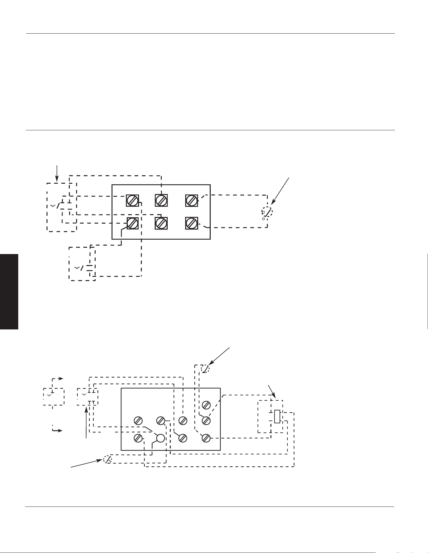
Figura 6 – Placa de Terminales de Control (para Calentadores con Contactores)
NOTAS: (Consulte la Tabla 3,
en la página 4, para ver los
Accesorios Eléctricos)
1. Este estilo de placa de
terminales de control se usa
con los modelos, excepto
804T09, 804T10 y 804T11.
2. Retire el puente de W1
a W2 cuando se usa un
termostato de 2 etapas.
3. En una unidad de
calentador, sólo se pueden
instalar un interruptor de
ventilador y un accesorio
de termostato.
4. Los termostatos con voltaje
de línea externo deben
tratarse como monofásicos
únicamente.
T
T
MT-1
MT-2
BLACK TO W1
RED TO R
BLACK
RED
RED
BLACK
C
R W1
W2
F2
F1
G
TR
T
S
FAN RELAY
(FOR MRFS-2 AMD MHRT)
2YU33
2YU95
Termostato interior
de 1 etapa
Interruptor (interior)
del termostato
de recuperación
térmica (2YU90)
Termostato interior
de 2 etapas
Interruptor (interior)
auxiliar del ventilador
para el verano (2YU82)
Relé auxiliar (interior) del
termostato de recuperación
térmica (2YU90)
MT-1
MT-2
BLACK
RED
RED
BLACK
P2
H2
F1
F2
S
P1
H1
2YU95
2YU 33
Figura 5 – Placa de Terminales de Control (para Calentadores sin Contactores)
NOTAS: (Consulte la Tabla 3, en la
página 4, para ver los Accesorios
Eléctricos)
1. Este estilo de placa de terminales
de control se usa con los modelos
804T09, 804T10, 804T11 y 804T18.
2. Cuando la unidad está cableada
para una fase, ponga el puente de
H1 a H2. Si se utiliza un termostato
unipolar con una unidad
monofásica, conecte los conductores
del termostato en P1 y H1.
3. Los termostatos con voltaje de
línea externo deben tratarse
como monofásicos únicamente.
Termostato
interior de
1 etapa
Termostato interior de 2 etapas
Interruptor (interior) auxiliar del
ventilador para el verano (2YU82)
Rojo
Negro
Rojo
Negro
Rojo
Negro
Rojo
Negro
Rojo a R
Negro
to W1
8-Sp
E
S
P
A
Ñ
O
L
Unidades de Calefacción Eléctricas
para Servicio Pesado Dayton
®
804RZ6 a 804RZ9, 804T01 a 804T22
Manual de Instrucciones de Operación y Lista de Partes Dayton
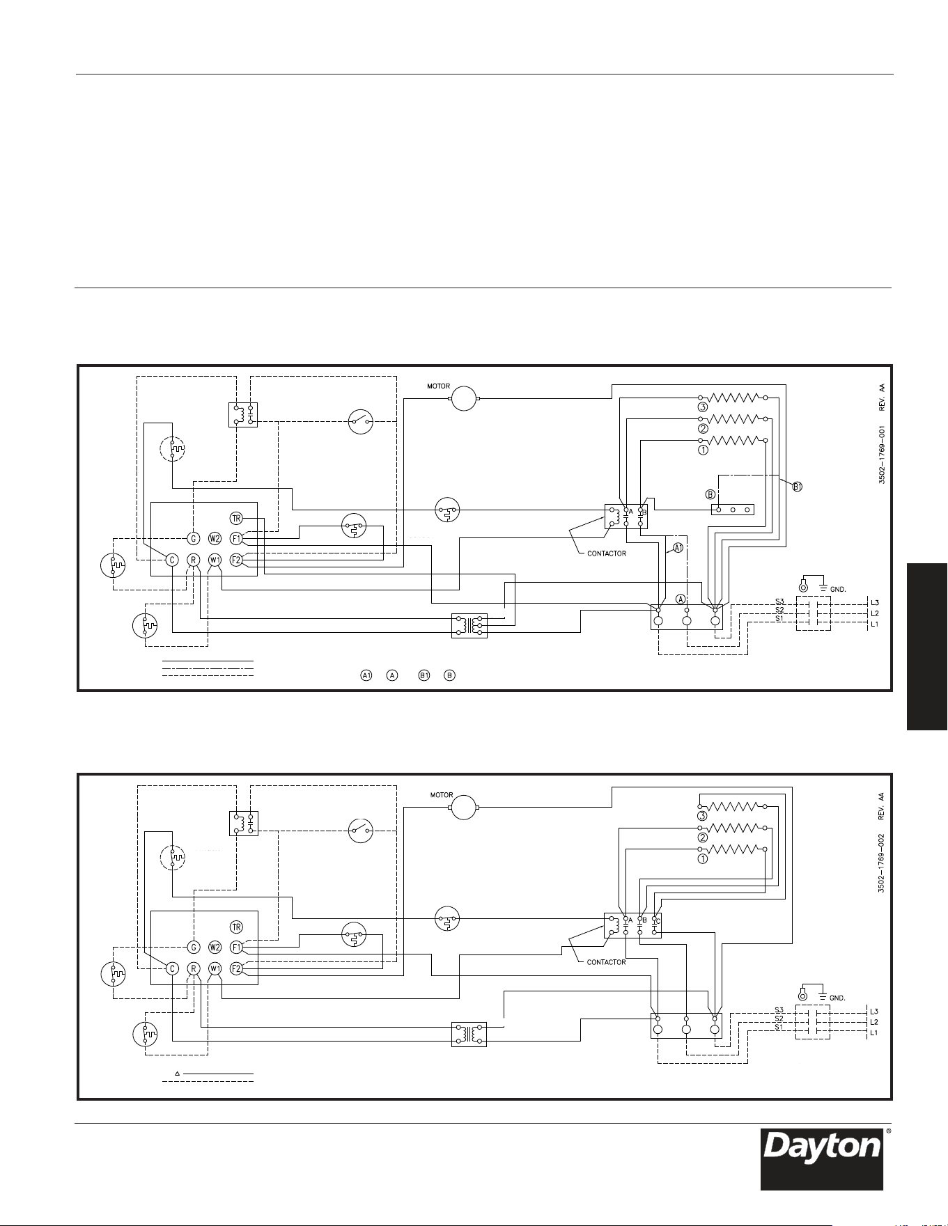
RELÉ DE
VENTILADOR
LÍMITE DE
RESET
MANUAL
INTERRUPTOR
DE VENTILADOR
DE VERANO
LIMITAR
EL RECORTE DE
SOBRECALENTAMIENTO
RETRASO DEL
VENTILADOR
TABLERO DE
TERMINALES
DE CONTROL
T-STAT DE
RECUPERACIÓN
DE CALOR
TERMOSTATO
TERMOSTATO
ROJO
ELEMENTO TRASERO
ELEMENTOS
BLOQUE DE
TERMINALES
TRIFÁSICO
EL CABLEADO DEL
CIRCUITO DE CONTROL
DEBE SER NEC CLASE 1
ADECUADO PARA 600V
INTERRUPTOR DE
DESCONEXIÓN DE
ENERGÍA
BLOQUE DE TERMINALES DE
ALIMENTACIÓN PARA USO
ÚNICAMENTE CON
CONDUCTORES DE COBRE.
UTILICE L1 Y L3 PARA
CONEXIONES MONOFÁSICAS
NEGRO
BLANCO
1 FASE CONECTADA
3 FASE CONECTADA
EQUIPAMIENTO OPCIONAL
INSTALADO EN CAMPO
FÁBRICA ALAMBRADA 1 FASE
PARA CONEXIÓN TRIFÁSICA
A AY
Diagrama 1: 3 elementos, monofásico y trifásico (modelos 804T21)
Diagrama 2: 3 elementos, trifásico (modelos 804T12, 804T19, 804T22 y 804RZ8)
RELÉ DE
VENTILADOR
LÍMITE DE
RESET
MANUAL
INTERRUPTOR
DE VENTILADOR
DE VERANO
RETRASO DEL
VENTILADOR
TABLERO DE
TERMINALES
DE CONTROL
T-STAT DE
RECUPERACIÓN
DE CALOR
TERMOSTATO
ELEMENTO TRASERO
ELEMENTOS
EL CABLEADO DEL
CIRCUITO DE CONTROL
DEBE SER NEC CLASE 1
ADECUADO PARA 600V
INTERRUPTOR DE
DESCONEXIÓN DE
ENERGÍA
BLOQUE DE TERMINALES DE
ALIMENTACIÓN PARA USO
ÚNICAMENTE CON
CONDUCTORES DE COBRE.
LIMITAR
EL RECORTE DE
SOBRECALENTAMIENTO
TERMOSTATO
NEGRO
FÁBRICA CON CABLE TRIFÁSICO
EQUIPAMIENTO OPCIONAL
INSTALADO EN CAMPO
9-Sp
Modelos 804RZ6 a 804RZ9, 804T01 a 804T22
Manual de Instrucciones de Operación y Lista de Partes Dayton
E
S
P
A
Ñ
O
L
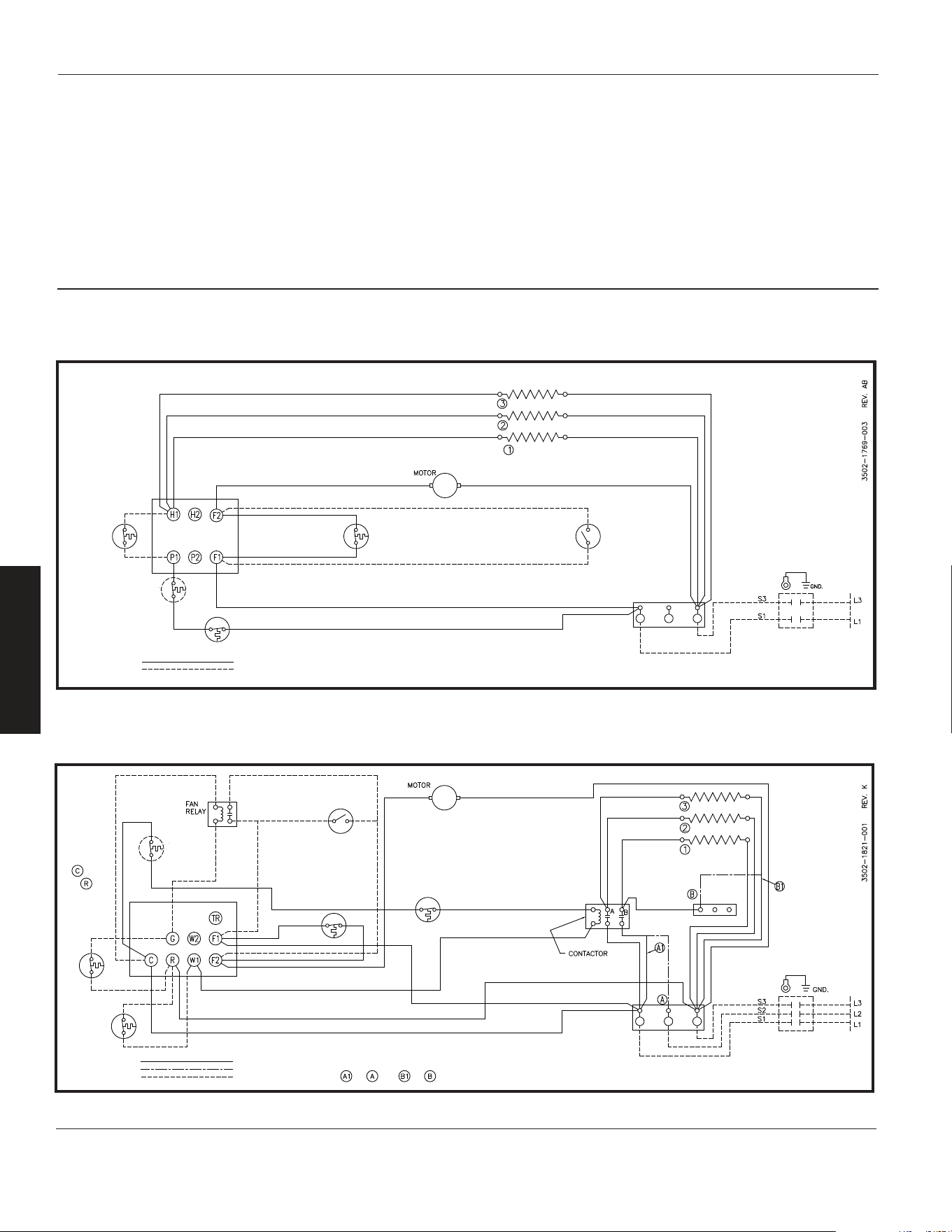
Diagram 3: 3 elementos, monofásico (Models 804T09, 804T10, 804T11 y 804T18)
ELEMENTO TRASERO
ELEMENTOS
TERMOSTATO
RETRASO DEL
VENTILADOR
INTERRUPTOR
DE VENTILADOR
DE VERANO
LÍMITE DE
RESET
MANUAL
LIMITAR
EL RECORTE DE
SOBRECALENTAMIENTO
CABLEADO DE FÁBRICA
EQUIPAMIENTO OPCIONAL
INSTALADO EN CAMPO
BLOQUE DE TERMINALES DE
ALIMENTACIÓN PARA USO
ÚNICAMENTE CON
CONDUCTORES DE COBRE.
INTERRUPTOR DE
DESCONEXIÓN DE
ENERGÍA
EL CABLEADO DEL
CIRCUITO DE CONTROL
DEBE SER NEC CLASE 1
ADECUADO PARA 600V
TABLERO DE
TERMINALES
DE CONTROL
Diagram 4: 3 elementos, monofásico y trifásico (Models 804T16 y 804T17)
ELEMENTO TRASERO
ELEMENTOS
TERMOSTATO
RETRASO DEL
VENTILADOR
RETRASO DEL
VENTILADOR
INTERRUPTOR
DE VENTILADOR
DE VERANO
LIMITAR
EL RECORTE DE
SOBRECALENTAMIENTO
BLOQUE DE TERMINALES DE
ALIMENTACIÓN PARA USO
ÚNICAMENTE CON
CONDUCTORES DE COBRE.
INTERRUPTOR DE
DESCONEXIÓN DE
ENERGÍA
EL CABLEADO DEL
CIRCUITO DE CONTROL
DEBE SER NEC CLASE 1
ADECUADO PARA 600V
BLOQUE DE
TERMINALES
TRIFÁSICO
UTILICE L1 Y L3 PARA
CONEXIONES MONOFÁSICAS
FÁBRICA ALAMBRADA 1 FASE
PARA CONEXIÓN TRIFÁSICA
A AY
SOLO VOLTAJE DE CONTROL INTERNO
T-STAT DE
RECUPERACIÓN
DE CALOR
CONECTE EL
CONTROL DE
VOLTAJE
EXTERNO
A
Y
TABLERO DE
TERMINALES
DE CONTROL
1 FASE CONECTADA
3 FASE CONECTADA
EQUIPAMIENTO OPCIONAL
INSTALADO EN CAMPO
LÍMITE DE
RESET
MANUAL
10
E
S
P
A
Ñ
O
L
-Sp
Unidades de Calefacción Eléctricas
para Servicio Pesado Dayton
®
804RZ6 a 804RZ9, 804T01 a 804T22
Manual de Instrucciones de Operación y Lista de Partes Dayton
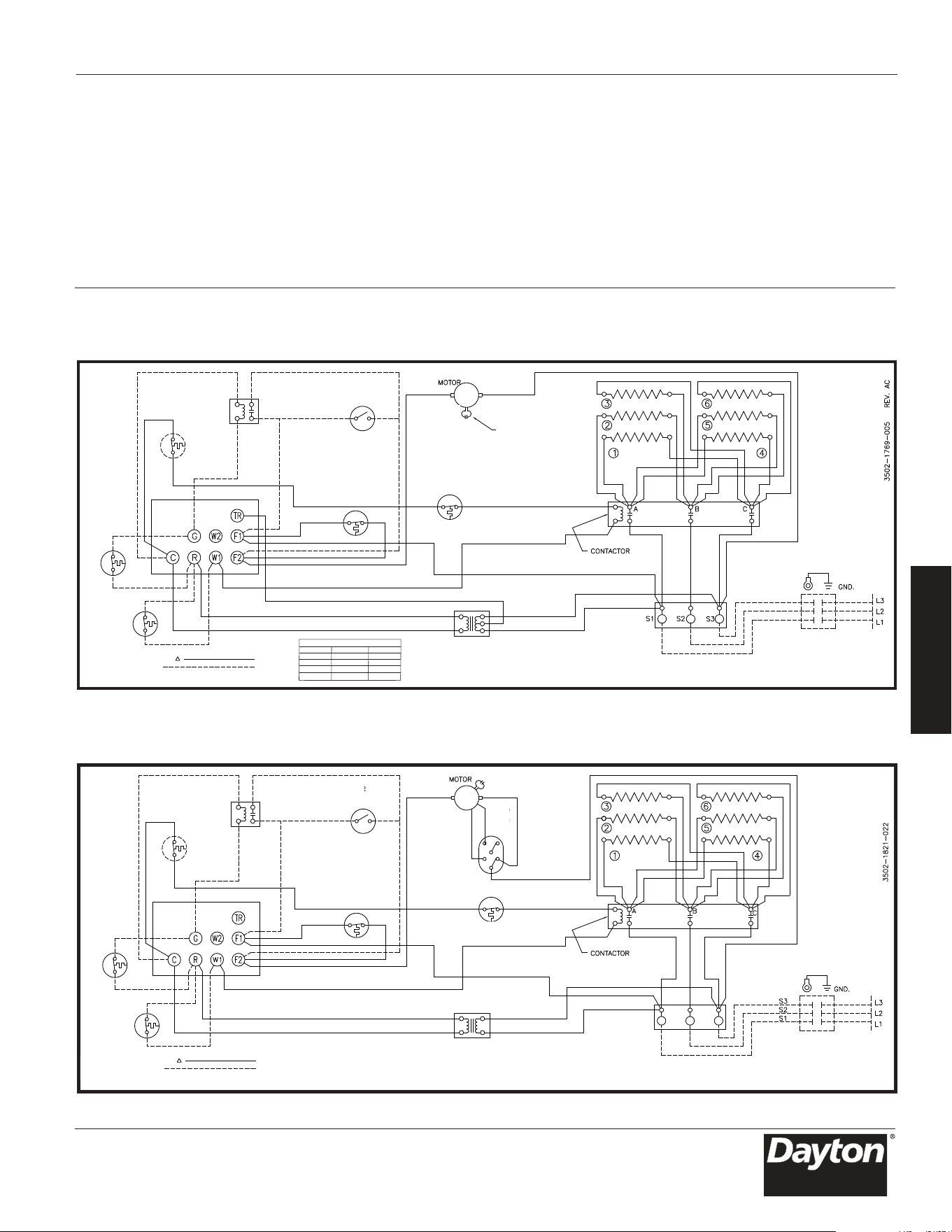
Diagramas de Cableado (Continuación)
Diagram 5: 6 elementos, trifásico (Models 804T01, 804T02, 804T03 y 804T04)
RETRASO DEL
VENTILADOR
INTERRUPTOR
DE VENTILADOR
DE VERANO
RETRASO DEL
VENTILADOR
RETRASO DEL
VENTILADOR
CONDENSADOR
SEGÚN SE REQUIERA
MARRÓNMARRÓN
T-STAT DE
RECUPERACIÓN
DE CALOR
TERMOSTATO
FÁBRICA CON CABLE TRIFÁSICO
EQUIPAMIENTO OPCIONAL
INSTALADO EN CAMPO
LIMITAR
EL RECORTE DE
SOBRECALENTAMIENTO
AMARILLO
AMARILLO
TRANSFORMADOR
BLANCO
CABLE 1
CABLE 2
XFMR CABLE GRÁFICO
VOLTAJE CABLE 1 CABLE 2
208V NEGRO ROJO
277V ROJO NEGRO
277V SIN CABLE VIOLETA
480V SIN CABLE NEGRO
TABLERO DE
TERMINALES
DE CONTROL
ELEMENTO TRASERO
ELEMENTOS ELEMENTOS
EL CABLEADO DEL
CIRCUITO DE CONTROL
DEBE SER NEC CLASE 1
ADECUADO PARA 600V
INTERRUPTOR DE
DESCONEXIÓN DE
ENERGÍA
BLOQUE DE TERMINALES
DE ALIMENTACIÓN PARA USO
CON CONDUCTORES AI O Cu
Diagram 6: 6 elementos, trifásico (Model 804T05 y 804T08)
RETRASO DEL
VENTILADOR
INTERRUPTOR
DE VENTILADOR
DE VERANO
RETRASO DEL
VENTILADOR
RETRASO DEL
VENTILADOR
INTERRUPTOR
DE VELOCIDAD
MARRÓN
ORG
BLANCO
ROJO
NEGRO
AZUL
ROJO
T-STAT DE
RECUPERACIÓN
DE CALOR
TERMOSTATO
FÁBRICA CON CABLE TRIFÁSICO
EQUIPAMIENTO OPCIONAL
INSTALADO EN CAMPO
LIMITAR
EL RECORTE DE
SOBRECALENTAMIENTO
TRANSFORMADOR
TABLERO DE
TERMINALES
DE CONTROL
ELEMENTO TRASE
REV. C
RO
ELEMENTOS ELEMENTOS
EL CABLEADO DEL
CIRCUITO DE CONTROL
DEBE SER NEC CLASE 1
ADECUADO PARA 600V
INTERRUPTOR DE
DESCONEXIÓN DE
ENERGÍA
BLOQUE DE TERMINALES
DE ALIMENTACIÓN PARA USO
CON CONDUCTORES AI O Cu
11-Sp
Modelos 804RZ6 a 804RZ9, 804T01 a 804T22
Manual de Instrucciones de Operación y Lista de Partes Dayton
E
S
P
A
Ñ
O
L
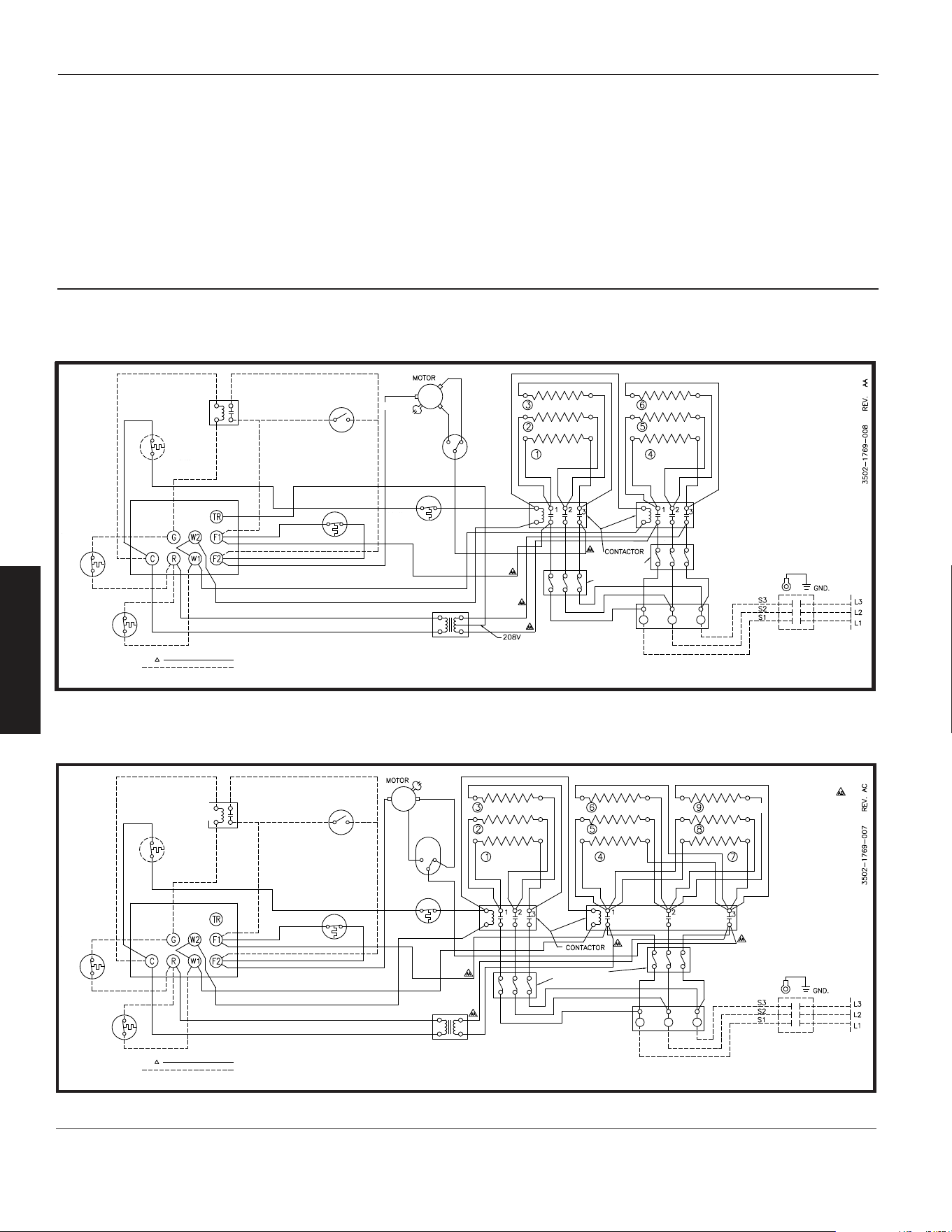
Diagrama 7: 6 elementos, 2 contratista, trifásico (modelo 804T07)
ELEMENTO TRASERO
ELEMENTOS ELEMENTOS
MARRÓN
MARRÓN
BLANCO
NEGRO
ROJO
ROJO
INTERRUPTOR
DE VELOCIDAD
INTERRUPTOR
DE VENTILADOR
DE VERANO
RETRASO DEL
VENTILADOR
RETRASO DEL
VENTILADOR
T-STAT DE
RECUPERACIÓN
DE CALOR
TERMOSTATO
TABLERO DE
TERMINALES
DE CONTROL
RETRASO DEL
VENTILADOR
LIMITAR
EL RECORTE DE
SOBRECALENT-
AMIENTO
FÁBRICA CON CABLE TRIFÁSICO
EQUIPAMIENTO OPCIONAL
INSTALADO EN CAMPO
TRANSFORMADOR
NEGRO
SOLAMENTE
BLOQUEO DE
FUSIBLES SI ES
NECESARIO
EL CABLEADO DEL
CIRCUITO DE CONTROL
DEBE SER NEC CLASE 1
ADECUADO PARA 600V
INTERRUPTOR DE
DESCONEXIÓN DE
ENERGÍA
BLOQUE DE TERMINALES
DE ALIMENTACIÓN PARA USO
CON CONDUCTORES AI O Cu
Diagrama 8:
9 elementos, 2 contratistas, trifásicos (modelos 804T13 y 804T15)
INTERRUPTOR
DE VENTILADOR
DE VERANO
NEGRO
ROJO
BLANCO
MARRÓN
MARRÓN
RETRASO DEL
VENTILADOR
T-STAT DE
RECUPERACIÓN
DE CALOR
TABLERO DE
TERMINALES
DE CONTROL
RETRASO DEL
VENTILADOR
TERMOSTATO
FÁBRICA CON CABLE TRIFÁSICO
EQUIPAMIENTO OPCIONAL
INSTALADO EN CAMPO
TRANSFORMADOR
INTERRUPTOR
DE VELOCIDAD
LIMITAR
EL RECORTE DE
SOBRECALENT-
AMIENTO
ELEMENTOS ELEMENTOS ELEMENTOS
ELEMENTO TRASERO
BLOQUEO DE
FUSIBLES SI ES
NECESARIO
BLOQUE DE TERMINALES
DE ALIMENTACIÓN PARA USO
CON CONDUCTORES AI O Cu
INTERRUPTOR DE
DESCONEXIÓN DE
ENERGÍA
EL CABLEADO DEL
CIRCUITO DE CONTROL
DEBE SER NEC CLASE 1
ADECUADO PARA 600V
LÍMITE DE
RESET
MANUAL
12
E
S
P
A
Ñ
O
L
-Sp
Unidades de Calefacción Eléctricas
para Servicio Pesado Dayton
®
804RZ6 a 804RZ9, 804T01 a 804T22
Manual de Instrucciones de Operación y Lista de Partes Dayton
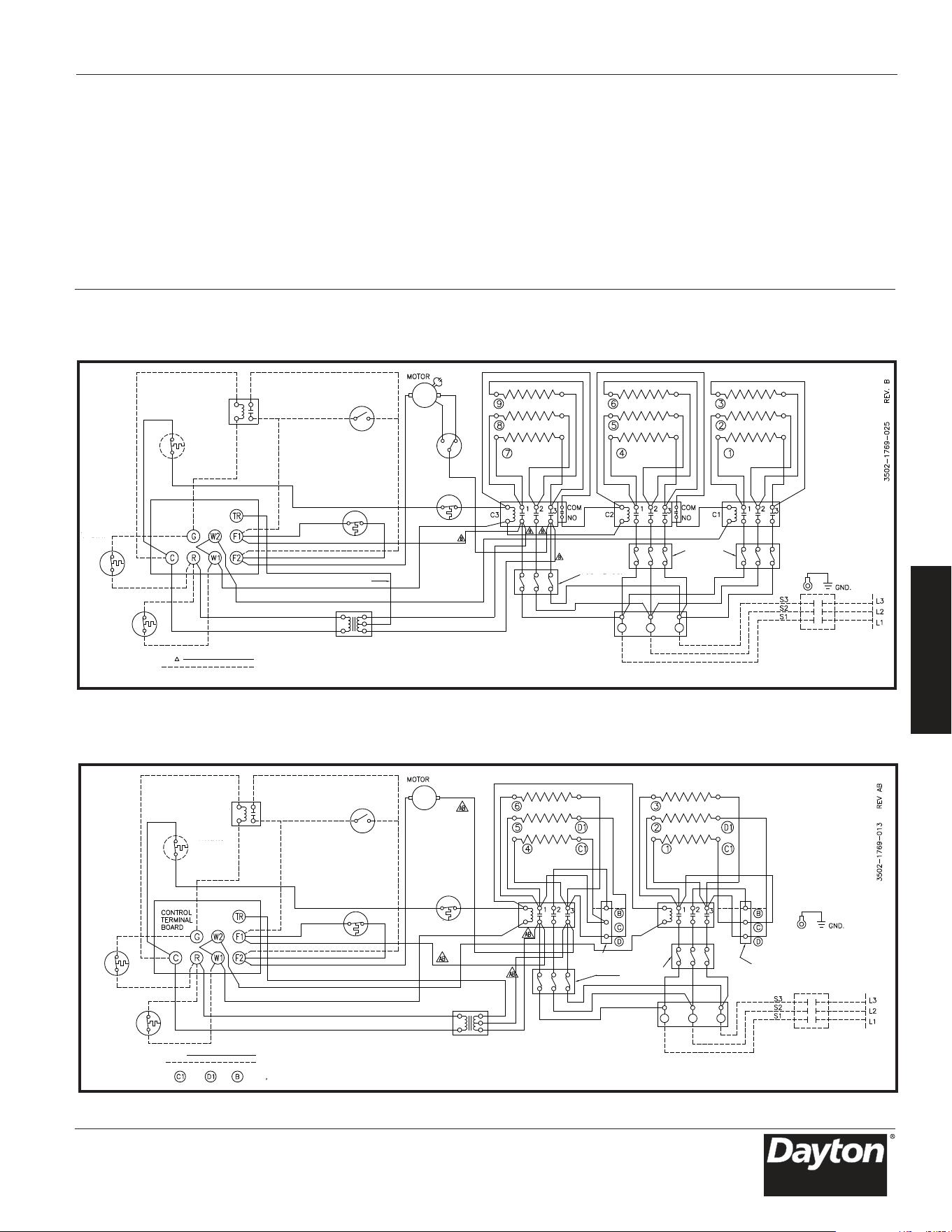
Diagramas de Cableado (Continuación)
Diagrama 9: 9 elementos, 3 contactores, trifásico (modelo 804T14)
NARANJA
208V (SOLO)
ROJO
ROJO
NEGRO
BLANCO
NEGRO
RELÉ DE
VENTILADOR
INTERRUPTOR
DE VENTILADOR
DE VERANO
TABLERO DE
TERMINALES
DE CONTROL
T-STAT DE
RECUPERACIÓN
DE CALOR
TERMOSTATO
FÁBRICA CON CABLE TRIFÁSICO
EQUIPAMIENTO OPCIONAL
INSTALADO EN CAMPO
RETRASO DEL
VENTILADOR
INTERRUPTOR
DE VELOCIDAD
LIMITAR EL RECORTE
DE SOBRECALENTAM-
IENTO
TRANSFORMADOR
MARRÓN
MARRÓN
ELEMENTOS ELEMENTOS ELEMENTOS
ELEMENTO TRASERO
INTERRUPTOR AUX
CUADRO DE LUCES
O FUSIBLES
CUADRO DE LUCES
O FUSIBLES
INTERRUPTOR AUX
BLOQUE DE TERMINALES DE ALIMENTACIÓN
PARA USO CON CONDUCTORES AI O Cu
EL CABLEADO DEL
CIRCUITO DE CONTROL
DEBE SER NEC CLASE 1
ADECUADO PARA 600V
INTERRUPTOR DE
DESCONEXIÓN DE
ENERGÍA
LÍMITE DE
RESET
MANUAL
Diagrama10: 6 elementos, monofásico y trifásico (Model 804RZ9)
BLANCO
ROJO
NEGRO
PLAZO TRIFÁSICO.
CUADRA
BLOQUE DE
FUSIBLES SI
ES NECESARIO
BLOQUE DE TERMINALES DE ALIMENTACIÓN
PARA USO CON CONDUCTORES AI O Cu
UTILICE L1 Y L3 PARA
CONEXIONES MONOFÁSICAS
RELÉ DE
VENTILADOR
INTERRUPTOR
DE VENTILADOR
DE VERANO
RETRASO DEL
VENTILADOR
TERMOSTATO
Y TERM CADA BLOQUE DE FASEA
MONOFÁSICO CONECTADO
EQUIPAMIENTO OPCIONAL
INSTALADO EN CAMPO
PARA CONEXIÓN TRIFÁSICA
TRANSFORMADOR
LIMITAR
EL RECORTE DE
SOBRECALENTAMIENTO
ELEMENTOS ELEMENTOS
ELEMENTO TRASERO
INTERRUPTOR DE
DESCONEXIÓN DE
ENERGÍA
EL CABLEADO DEL
CIRCUITO DE CONTROL
DEBE SER NEC CLASE 1
ADECUADO PARA 600V
PLAZO TRIFÁSICO.
CUADRA
INTERRUPTOR SÓLO PARA TRIFÁSICO
T-STAT DE
RECUPERACIÓN
DE CALOR
LÍMITE DE
RESET
MANUAL
13-Sp
Modelos 804RZ6 a 804RZ9, 804T01 a 804T22
Manual de Instrucciones de Operación y Lista de Partes Dayton
E
S
P
A
Ñ
O
L
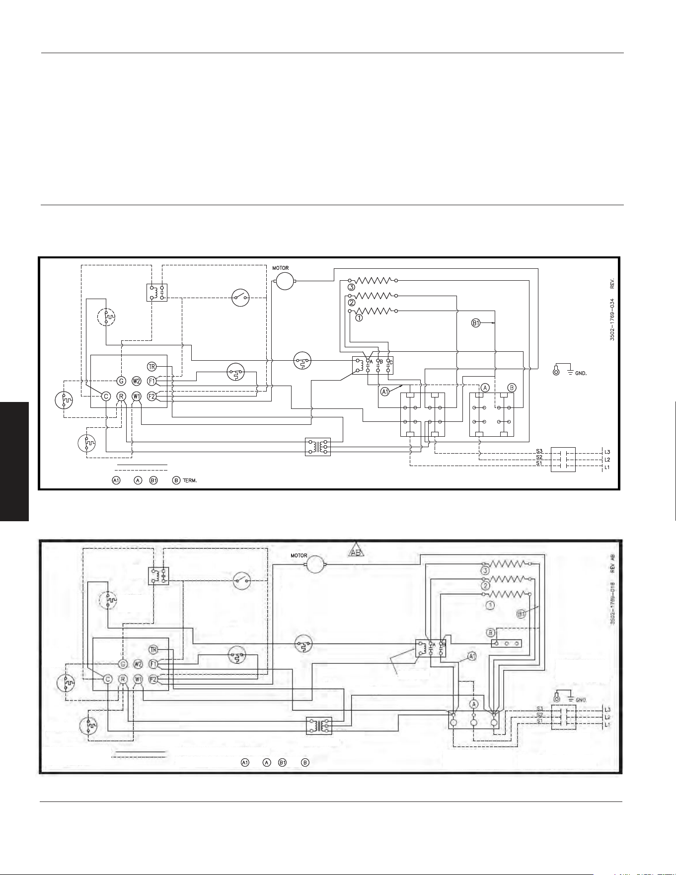
Diagramas de Cableado (Continuación)
Diagrama 11: 3 elementos, monofásicos y trifásicos (804RZ6)
14
E
S
P
A
Ñ
O
L
-Sp
Unidades de Calefacción Eléctricas
para Servicio Pesado Dayton
®
804RZ6 a 804RZ9, 804T01 a 804T22
Manual de Instrucciones de Operación y Lista de Partes Dayton
B
Elemento posterior
Elementos
Este bloque reside más cercano a
las terminales de element
Interruptor solo para 3 fases
El cableado del circuito
de control deberá ser
de Clase 1 del Código
Eléctrico Nacional (NEC)
y adecuado para 600 V
Bloque de terminales de
alimentación para uso con
conductores de cobre únicamente
Usa L1 y L3 para conexiones
monofásicas
Interruptor de
desconexión
de energía
Retraso del
ventilador
Transformador
Negro
Blanco
Rojo
Inte
rruptor
del ventilador
para el verano
T-Stat de
recuperación
de calor
Tablero de
terminales
de control
Relé del
ventilador
Límite de
reposición
manual
Equipamiento opcional
Monofásico conectado
Instalado en campo
Para conexión trifásica
Para Y Para
T
ermostato
Interruptor
limitador de
sobretemperatura
Diagram 12: 3 elementos, monofásicos y trifásicos (modelo 804T20)
El cableado del circuito
de control deberá ser
de Clase 1 del Código
Eléctrico Nacional (NEC)
y adecuado para 600 V
Bloque de terminales de
alimentación para uso con
conductores de cobre únicamente
Usa L1 y L3 para conexiones
monofásicas
Interruptor solo
para 3 fases
Transformador
Contractor
Blanc
Negro
Negro
Negro
Rojo
Interruptor
limitador de
sobretemperatura
Inte
rruptor
del ventilador
para el verano
Retraso del
ventilador
Relé del
ventilador
Límite de
reposición
manual
Tablero de
terminales
de control
T-Stat de
recuperación
de calor
T
ermostato
Equipamiento opcional
Monofásico conectado Cableado de fábrica para monofásico
Instalado en campo Para conexión trifásica
Para Y Para
Elemento posterior
Elementos
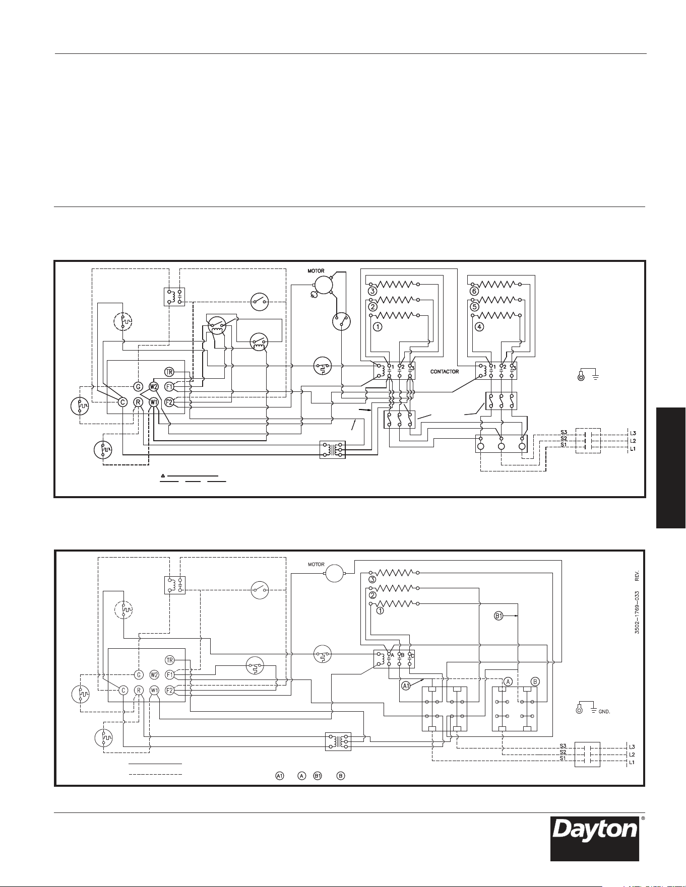
Diagramas de Cableado (Continuación)
Transformador
Elemento posterior
Elementos
El cableado del circuito
de control deberá ser
de Clase 1 del Código
Eléctrico Nacional (NEC)
y adecuado para 600 V
Bloque de terminales de
alimentación para uso con
conductores de cobre únicamente
Usa L1 y L3 para conexiones
monofásicas
Interruptor de
desconexión
de energía
B
Negro
Rojo
Interruptor
del ventilador
para el verano
Relé del
ventilador
Límite de
reposición
manual
Monofásico conectado
Cableado de fábrica monofásico
para conexión trifásica
Equipamiento opcional
Instalado en campo
Interruptor
limitador de
sobretemperatura
Retraso del
ventilador
Tablero de
terminales
de control
Tablero de
terminales
de control
T-Stat de
recuperación
de calor
Termostato
Este bloque reside más cercano a
las terminales de element
Interruptor solo para 3 fases
Para Y Para
Diagrama 14: 3 elementos, monofásicos y trifásicos (modelo 804RZ7)
15-Sp
Modelos a thru 804RZ9, 804T01 a 804T22
Manual de Instrucciones de Operación y Lista de Partes Dayton
E
S
P
A
Ñ
O
L
Diagrama 13:
6 elementos, 2 c ontactores, trifásicos (modelo 804T06)
Termostato
Termostato de
recuperación
térmica
Cableado de fábrica para trifásico
Equipo opcional instalado
en el campo
Relé del
ventilador
Límite de
reposición
manual
Interruptor
del ventilador
para el verano
Interruptor
limitador de
sobretemperatura
Interruptor
de velocidad
Blanco
Roja
Negro
Marrón
Marrón
Transformador
Negro
Negro
(240 V únicamente)
Rojo
Elemento posterior
Elementos
Elementos
Bloque de
fusibles de
ser necesario
3502-1769-019 REV. AA
Interruptor para
trifásico solamente
El cableado del circuito
de control deberá ser
de Clase 1 del Código
Eléctrico Nacional (NEC)
y adecuado para 600 V
Tierra
Interruptor de
desconexión de
la alimentación
Bloque de terminales de
alimentación para uso con
conductores de cobre únicamente
Relé
temporizador
Relé
temporizador

Lista de Partes de Reparación para las Unidades de Calefacción Eléctricas para Servicio Pesado
Ref. 1 Ref. 2 Ref. 3 Muelle Ref. 5 Ref. 6 Ref. 7
Resorte del
elemento
Resorte de
tubo capilar
Ref. 4 Soporte de
montaje
Extensión de
soporte
Soporte de
interruptor
Ref. 8
Modelo Cambiar
Retraso del
ventilador
Ref. 17 Ref. 18 Ref. 19
Ref. 10 Ref. 11
Ref. 12
Ref. 13 Protector de
límite lineal
Ensamblaje Guardia
elemental
Ref. 20
Modelo
Transformador
Motor
Aspa del
ventilador
La tapa Abrazadera
de retención
del elemento
de elementos
16
E
S
P
A
Ñ
O
L
-Sp
Unidades de Calefacción Eléctricas
para Servicio Pesado Dayton
®
804RZ6 a 804RZ9, 804T01 a 804T22
Manual de Instrucciones de Operación y Lista de Partes Dayton
804T10 5208-0073-000 5208-0072-000 5208-0074-000 – – – 1215-0256-000 4520-0010-000
804T12 5208-0073-000 5208-0072-000 5208-0074-000 – – – 1215-0256-000 4520-0010-000
804T11 5208-0073-000 5208-0072-000 5208-0074-000 – – – 1215-0256-000 4520-0010-000
804T09 5208-0073-000 5208-0072-000 5208-0074-000 – – – 1215-0256-000 4520-0010-000
804T17 5208-0073-000 5208-0072-000 5208-0074-000 – – – 1215-0256-000 4520-0010-000
804T19 5208-0073-000 5208-0072-000 5208-0074-000 – – – 1215-0256-000 4520-0010-000
804T18 5208-0073-000 5208-0072-000 5208-0074-000 – – – 1215-0256-000 4520-0010-000
804T16 5208-0073-000 5208-0072-000 5208-0074-000 – – – 1215-0256-000 4520-0010-000
804T21 5208-0073-000 5208-0072-000 5208-0074-000 – – – 1215-0256-000 4520-0010-000
804T22 5208-0073-000 5208-0072-000 5208-0074-000 – – – 1215-0256-000 4520-0010-000
804T20 5208-0073-000 5208-0072-000 5208-0074-000 – – – 1215-0256-000 4520-0010-000
804RZ7 5208-0073-000 5208-0072-000 5208-0074-000 – – – 1215-0256-000 4520-0010-000
804RZ8 5208-0073-000 5208-0072-000 5208-0074-000 – – – 1215-0256-000 4520-0010-000
804RZ6 5208-0073-000 5208-0072-000 5208-0074-000 – – – 1215-0256-000 4520-0010-000
804T01 5208-0073-000 5208-0072-000 5208-0074-000 – – 1215-0282-000 1215-0256-000 4520-0010-000
804T02 5208-0073-000 5208-0072-000 5208-0074-000 – – 1215-0282-000 1215-0256-000 4520-0010-000
804RZ9 5208-0073-000 5208-0072-000 5208-0074-000 – – 1215-0282-000 1215-0256-000 4520-0010-000
804T03 5208-0073-000 5208-0072-000 5208-0074-000 – – 1215-0282-000 1215-0256-000 4520-0010-000
804T04 5208-0073-000 5208-0072-000 5208-0074-000 – – 1215-0282-000 1215-0256-000 4520-0010-000
804T05 5208-0073-001 5208-0072-000 5208-0074-000 5216-2053-000 1215-2258-000 – 1215-0256-000 4520-0010-000
804T07 5208-0073-001 5208-0072-000 5208-0074-000 5216-2053-000 1215-2258-000 – 1215-0256-000 4520-0010-000
804T08 5208-0073-001 5208-0072-000 5208-0074-000 5216-2053-000 1215-2258-000 – 1215-0256-000 4520-0010-000
804T06 5208-0073-001 5208-0072-000 5208-0074-000 5216-2053-000 1215-2258-000 – 1215-0256-000 4520-0010-000
804T13 5208-0073-001 5208-0072-000 5208-0074-000 5216-2053-000 1215-2258-000 1215-0282-000 1215-0256-000 4520-0010-000
804T14 5208-0073-001 5208-0072-000 5208-0074-000 5216-2053-000 1215-2258-000 1215-0282-000 1215-0256-000 4520-0010-000
804T15 5208-0073-001 5208-0072-000 5208-0074-000 5216-2053-000 1215-2258-000 1215-0282-000 1215-0256-000 4520-0010-000
804T10 – 3900-2002-006 1210-2000-000 1402-0336-002 4520-0011-000 1802-0087-000 2504-0011-003 –
804T12 5814-0003-002 3900-2005-000 1210-2000-000 1402-0336-002 4520-0011-000 1802-0087-002 2504-0011-003 –
804T11 – 3900-2002-007 1210-2000-000 1402-0336-002 4520-0011-000 1802-0087-001 2504-0011-003 –
804T09 – 3900-2002-006 1210-2000-000 1402-0336-002 4520-0011-000 1802-0087-024 2504-0011-003 –
804T17 – 3900-2002-006 1210-2000-000 1402-0336-002 4520-0011-000 1802-0087-035 2504-0011-003 –
804T19 5814-0003-002 3900-2005-000 1210-2000-000 1402-0336-002 4520-0011-000 1802-0087-005 2504-0011-003 –
804T18 – 3900-2002-007 1210-2000-000 1402-0336-002 4520-0011-000 1802-0087-004 2504-0011-003 –
804T16 – 3900-2002-006 1210-2000-000 1402-0336-002 4520-0011-000 1802-0087-034 2504-0011-003 –
804T21 5814-0003-000 3900-2014-002 1210-0090-000 1402-0339-004 4520-0011-001 1802-0087-006 2504-0013-003 –
804T22 5814-0003-002 3900-0347-005 1210-0090-000 1402-0339-004 4520-0011-001 1802-0087-008 2504-0013-003 –
804T20 5814-0003-000 3900-2014-001 1210-0090-000 1402-0339-004 4520-0011-001 1802-0087-031 2504-0013-003 –
804RZ7 5814-0003-000 3900-2014-002 1210-0090-000 1402-0339-004 4520-0011-001 1802-0087-031 2504-0013-003 –
804RZ8 5814-0003-002 3900-0347-005 1210-0090-000 1402-0339-004 4520-0011-001 1802-0087-011 2504-0013-003 –
804RZ6 5814-0003-000 3900-2014-001 1210-0090-000 1402-0339-004 4520-0011-001 1802-0087-036 2504-0013-003 –
804T01 5814-0003-000 3900-0361-000 1210-0090-001 1402-0339-004 4520-0011-001 1802-0087-012 2504-0012-003 –
804T02 5814-0003-002 3900-0361-001 1210-0090-001 1402-0339-004 4520-0011-001 1802-0087-008 2504-0012-003 –
804RZ9 5814-0003-000 3900-0361-000 1210-0090-001 1402-0339-004 4520-0011-001 1802-0087-037 2504-0012-003 –
804T03 5814-0003-000 3900-0362-000 1210-0096-000 1402-0339-004 4520-0011-001 1802-0087-037 2504-0012-003 482028000
804T04 5814-0003-002 3900-0362-001 1210-0096-000 1402-0339-004 4520-0011-001 1802-0087-011 2504-0012-003 482028000
804T05 5814-0003-000 3900-0364-000 1210-0098-000 1402-0340-004 4520-0011-002 1802-0087-018 2504-0014-003 482028000
804T07 5814-0003-002 3900-2065-000 1210-0098-000 1402-0340-004 4520-0011-002 1802-0087-017 2504-0014-003 482028000
804T08 5814-0003-002 3900-2065-000 1210-0098-000 1402-0340-004 4520-0011-002 1802-0087-019 2504-0014-003 482028000
804T06 5814-0003-000 3900-0364-000 1210-0098-000 1402-0340-004 4520-0011-002 1802-0087-028 2504-0014-003 482028000
804T13 5814-0003-002 3900-0350-001 1210-11004-000 1402-0340-005 4520-0011-002 1802-0087-021 2504-0015-003 482028000
804T14 5814-2021-001 3900-0350-000 1210-11004-000 1402-0340-005 4520-0011-002 1802-0087-022 2504-0015-003 482028000
804T15 5814-0003-002 3900-0350-001 1210-11004-000 1402-0340-005 4520-0011-002 1802-0087-023 2504-0015-003 482028000

(Continuación)
804T10 – – - – – 23901-00160 21424-17128
804T12 – – 5018-0004-100 2900-0030-000 – 23901-00160 21424-17128
804T11 – – – 2900-0030-000 – 23901-00160 21424-17128
804T09 – – – – – 23901-00160 21424-17128
804T17 – – – – – 23901-00160 21424-17128
804T19 – – 5018-0004-100 2900-0030-000 – 23901-00160 21424-17128
804T18 – – – 2900-0030-000 – 23901-00160 21424-17128
804T16 – – – – – 23901-00160 21424-17128
804T21 – 3504-7002-001 5018-0005-004 – – – –
804T22 – 3504-7002-001 – 2900-0030-000 – – –
804T20 – 3504-7002-001 5018-0003-000 – – – –
804RZ7 – 3504-7002-001 5018-0005-004 – – – –
804RZ8 – 3504-7002-001 – 2900-0030-000 – – –
804RZ6 – 3504-7002-001 5018-0005-004 – – – –
804T01 – 3504-7002-001 5018-0005-004 – – – –
804T02 – 3504-7002-001 5018-0004-100 2900-0030-000 – – –
804RZ9 – 3504-7002-001 5018-0005-004 – – – –
804T03 1432-0002-003 3504-7002-001 5018-0006-000 – – – –
804T04 1432-0002-003 3504-7002-001 5018-0005-004 2900-0030-000 –- –
804T05 1432-0002-003 3504-7002-001 – – 25221-60131 – –
804T07 1432-11004-000 3504-7002-001 5018-0005-004 2900-0030-000 25221-60131 – –
804T08 1432-11004-000 3504-7002-001 5018-0005-004 2900-0030-000 25221-60131 – –
804T06 1432-0002-001 3504-7002-001 5018-0006-000 – 25221-60131 – –
804T13 1432-0002-004 3504-7002-001 * 2900-0030-000 25221-60131 – –
804T14 1432-0002-004 3504-7002-001 5018-0005-004 – 25221-60131 – –
804T15 1432-0002-004 3504-7002-001 ** 2900-0030-000 25221-60131 – –
804T10 3503-2004-106 5208-7005-001 5823-0004-000 5823-0001-000 – – –
804T12 3503-2004-106 5208-7005-001 5823-0004-000 5823-0002-000 – – –
804T11 3503-2004-106 5208-7005-001 5823-0004-000 5823-0001-000 – – –
804T09 3503-2004-106 5208-7005-001 5823-0004-000 5823-0001-000 – – –
804T17 3503-2004-106 5208-7005-001 5823-0004-000 5823-0001-000 5823-0003-000 – –
804T19 3503-2004-106 5208-7005-001 5823-0004-000 5823-0002-000 – – –
804T18 3503-2004-106 5208-7005-001 5823-0004-000 5823-0001-000 – – –
804T16 3503-2004-106 5208-7005-001 5823-0004-000 5823-0001-000 5823-0003-000 – –
804T21 3503-2004-107 5208-7005-001 5823-11012-000 5823-0002-000 – – –
804T22 3503-2004-107 5208-7005-001 5823-0004-000 5823-0002-000 – – –
804T20 3503-2004-107 5208-7005-001 5823-0004-008 5823-0002-000 5823-0003-000 – –
804RZ7 3503-2004-107 5208-7005-001 5823-11012-000 5823-0002-000 – – –
804RZ8 3503-2004-107 5208-7005-001 5823-0004-000 5823-0002-000 – – –
804RZ6 3503-2004-107 5208-7005-001 5823-11012-000 5823-0002-000 – – –
804T01 3503-2004-107 5208-7005-001 5823-0004-001 5823-0002-000 – – –
804T02 3503-2004-107 5208-7005-001 5823-0004-000 5823-0002-000 – – –
804RZ9 3503-2004-107 5208-7005-001 5823-0004-003 5823-0002-000 5823-0003-000 2025-0002-000 2019-0007-010
804T03 3503-2004-107 5208-7005-001 5823-0004-002 5823-0002-000 – – –
804T04 3503-2004-107 5208-7005-001 5823-0004-002 5823-0002-000 – – –
804T05 3503-2004-108 5208-7005-001 5823-0004-003 5823-0002-000 – 480030004 2019-7008-079
804T07 3503-2004-108 5208-7005-001 5823-0004-002 5823-0002-000 – – –
804T08 3503-2004-108 5208-7005-001 5823-0004-001 5823-0002-000 – – –
804T06 3503-2004-108 5208-7005-001 5823-0005-000 5823-0002-000 – 480030004 2019-7008-080
804T13 3503-2004-108 5208-7005-001 5823-0004-002 5823-0002-000 – – –
804T14 3503-2004-108 5208-7005-001 5823-0005-000 5823-0002-000 – 480030004 2019-7008-079
804T15 3503-2004-108 5208-7005-001 5823-0004-002 5823-0002-000 – *** ****
Ref. 22 Ref. 26 Ref. 27
Ref. 21 Orejeta Termi- Ref. 23 Ref. 24 Ref. 25 Arandela Tornillo
Modelo Capacitor nal de tierra Relé Aislador Buje de Tierra de Tierra
Ref. 29 Bloque de
03.ef
Bloque de Ref. 33
Ref. 28 Rejilla T
R
erminales de Treminales
Ref. 31
Bloque de
Term
Ref. 32
inales Bloque Ref. 34
Mo Rejilladelo Elástica Alimentación de Control Trifásico de Fusibles Fusible
17-Sp
Modelos 804RZ6 a 804RZ9, 804T01 a 804T22
Manual de Instrucciones de Operación y Lista de Partes Dayton
E
S
P
A
Ñ
O
L
*Debe usar un termostato de dos etapas en la operación de 3Ø.
**Se utilizan dos relés, relé de 50A 5018-0006-000 y relé de 35A 5018-0004-100
***Se utilizan dos relés, relé de 50A 5018-0006-000 y relé de 35A 5018-0004-100
****Se utilizan dos estilos de fusibles, (30 A) 600 V 2019-7002-008 y (50 A) 600 V 2019-7002-012

18-Sp
Síntoma Causa(s) Posible(s) Medida Correctiva
El termostato requiere
calor, pero el calentador
no funciona
El motor del ventilador
se “calienta”
El motor del ventilador
funciona, pero no
hay calefacción
1. Fusible abierto (quemado)
2. Cableado incorrecto
3. Interruptor térmico abierto, el elemento
del calentador y el circuito de control
se desenergizan
1. Acumulación de polvo o demasiada
suciedad en el motor del ventilador
2. Acumulación de suciedad
3. El motor necesita lubricación
1. El contacto del elemento no funciona
correctamente
2. El fusible del elemento está quemado
1. Reemplace los fusibles, verifique la causa
del problema (consulte la Lista de partes de
reparación para ver los tamaños de fusible)
2. Revise las conexiones del cableado
3. Verifique lo siguiente:
Voltaje y fase correctos de la alimentación.
Cableado de control correcto (el control del
calentador debe ser a través de la sección
de cableado de control del termostato
únicamente). Interrupción de la alimentación
para el calentador durante el funcionamiento
del mismo. Restricción del aire alrededor del
calentador. Purga del ventilador de1a 5
minutos después de que el termostato apaga
1. Limpie las acumulaciones de grasa y aceite
del alojamiento y del motor del ventilador
2. Limpie las rejillas y entre los elementos de
calefacción
3. Consulte la sección de Mantenimiento
1. Revise el cableado para ver si hay un circuito
abierto. Reemplace el contactor si éste
está defectuoso
2. Reemplace los fusibles, verifique la causa
del problema
Tabla de Identificación de Problemas
E
S
P
A
Ñ
O
L
Unidades de Calefacción Eléctricas
para Servicio Pesado Dayton
®
804RZ6 a 804RZ9, 804T01 a 804T22
Manual de Instrucciones de Operación y Lista de Partes Dayton

Dayton Operating Instructions and Parts Manual
19
E
N
G
L
I
S
H
Manufactured for Dayton Electric Mfg. Co.
Lake Forest, Illinois 60045 U.S.A.
804RZ6 a 804RZ9, 804T01 a 804T22
Dayton Operating Instructions and Parts Manual
LIMITED WARRANTY
DAYTON ONE-YEAR LIMITED WARRANTY. DAYTON
®
HEAVY-DUTY ELECTRIC UNIT HEATERS, MODELS COVERED IN
THIS MANUAL, ARE WARRANTED BY DAYTON ELECTRIC MFG. CO. (DAYTON) TO THE ORIGINAL USER AGAINST DEFECTS
IN WORKMANSHIP OR MATERIALS UNDER NORMAL USE FOR ONE YEAR AFTER DATE OF PURCHASE. ANY PART WHICH IS
DETERMINED TO BE DEFECTIVE IN MATERIAL OR WORKMANSHIP AND RETURNED TO AN AUTHORIZED SERVICE LOCATION,
AS DAYTON
DESIGNATES, SHIPPING COSTS PREPAID, WILL BE, AS THE EXCLUSIVE REMEDY, REPAIRED OR REPLACED AT
DAYTON’S OPTION. FOR LIMITED WARRANTY CLAIM PROCEDURES, SEE “PROMPT DISPOSITION” BELOW. THIS LIMITED
WARRANTY GIVES PURCHASERS SPECIFIC LEGAL RIGHTS WHICH VARY FROM JURISDICTION TO JURISDICTION.
LIMITATION OF LIABILITY. TO THE EXTENT ALLOWABLE UNDER APPLICABLE LAW, DAYTON’S LIABILITY FOR CONSEQUENTIAL
AND INCIDENTAL DAMAGES IS EXPRESSLY DISCLAIMED. DAYTON’S LIABIL
ITY IN ALL EVENTS IS LIMITED TO AND SHALL NOT
EXCEED THE PURCHASE PRICE PAID.
WARRANTY DISCLAIMER. A DILIGENT EFFORT HAS BEEN MADE TO PROVIDE PRODUCT INFORMATION AND ILLUSTRATE
THE PRODUCTS IN THIS LITERATURE ACCURATELY; HOWEVER, SUCH INFORMATION AND ILLUSTRATIONS ARE FOR THE SOLE
PURPOSE OF IDENTIFICATION, AND DO NOT EXPRESS OR IMPLY A WARRANTY THAT THE PRODUCTS ARE MERCHANTABLE,
OR FIT FOR A PARTICULAR PURPOSE, OR THAT THE PRODUCTS WILL NECESSARILY CONFORM TO THE ILLUS
TRATIONS OR
DESCRIPTIONS. EXCEPT AS PROVIDED BELOW, NO WARRANTY OR AFFIRMATION OF FACT, EXPRESSED OR IMPLIED, OTHER
THAN AS STATED IN THE “LIMITED WARRANTY” ABOVE IS MADE OR AUTHORIZED BY DAYTON.
Technical Advice and Recommendations, Disclaimer. Notwithstanding any past practice or dealings or trade custom,
sales shall not include the furnishing of technical advice or assistance or system design. Dayton assumes no obligations or
liability on account of any unauthor
ized recommendations, opinions or advice as to the choice, installation or use of
products.
Product Suitability. Many jurisdictions have codes and regulations governing sales, construction, installation, and/or use
of products for certain purposes, which may vary from those in neighboring areas. While attempts are made to assure that
Dayton products comply with such codes, Dayton cannot guarantee compliance, and cannot be responsible for how the
product is instal
led or used. Before purchase and use of a product, review the product applications, and all applicable
national and local
codes and regulations, and be
sure that the product, installation, and use will comply with them.
Certain aspects of disclaimers are not applicable to consumer products; e.g., (a) some jurisdictions do not allow the exclusion
or limitation of incidental or consequential damages, so the above limitation or exclusion may not apply to you; (b) also,
some
jurisdictions do not allow a limitation on how long an implied warranty lasts, consequently the above limitation
may not apply to you; and (c) by law, during the period of this Limited Warranty, any implied warranties of implied
merchantability or fitness for a particular purpose applicable to consumer products purchased by consumers, may not
be excluded or otherwise disclaimed.
Prompt Disposition. A good faith effort will be made for prompt correction or other adjustm
ent with respect to any
product which proves to be defective within limited warranty. For any product believed to be defective within limited
warranty, first write or call dealer from whom the product was purchased. Dealer will give additional directions. If unable to
resolve satisfactorily, write to Dayton at address below, giving dealer’s name, address, date, and number of dealer’s invoice,
and describing the nature of the defect. Title and risk of loss pass to buyer on
delivery to common carrier. If product was
damaged in transit to you, file claim with carrier.
Manufactured for Dayton Electric Mfg. Co., 100 Grainger Parkway, Lake Forest, Illinois 60045-5201 U.S.A.
Models 804RZ6 a 804RZ9, 804T01 a 804T22

20-Sp
804RZ6 a 804RZ9, 804T01 a 804T22
Manual de Instrucciones de Operación y Lista de Partes Dayton
E
S
P
A
Ñ
O
L
Notas
F
R
A
N
Ç
A
I
S
Manuel d’utilisation et de pièces détachées
Lire et conserver ces instructions. Il faut les lire attentivement avant de commencer à assembler, installer, faire
fonctionner ou entretenir l'appareil décrit. Pour se protéger et protéger autrui, observer toutes les informations sur la sécurité. Négliger d'appliquer
ces instructions peut causer des blessures corporelles et/ou des dommages matériels! Conserver ces instructions pour références ultérieures.
Radiateurs électriques à
usage industriel Dayton
®
CARACTÉRISTIQUES
• Appareils de 5 à 15 kW convertibles
sur site de monophasé à triphasé
• Le circuit de commande basse tension
24 volts est standard sauf sur les
appareils de 3 ou 5kW, 208 V, 240/
208 V, ou277 V qui disposent d'une
commande sur tension secteur
• Moteur sous carter de grande
puissance
• Élément chauffant à revêtement en
acier, plaqué cuivre, et ailettes en
aluminium
• Un louvre d’admission perfectionné
transmet l’air froid sur l’élément
chauffant pour un rendement
amélioré
• Protection therm
iqu
e linéaire à
réarmement automatique
• Évacuation d’air de type Venturi
avec grandes pales de ventilateur
équilibrées dynamiquement
• Boîtier en acier embouti de forte
épaisseur
• Supports verticaux et horizontaux
disponibles en option
Figure 1
Puissance Tension Tension Moteur du Débit Vitesse de Élévation Portée
nominale BTU/h radiateur/ de A par ventilateur en sortie l’air en temp. horiz. du
Modèle kW (x 1 000) moteur Phase comm. phase CV Tr/min (m
3
/min) sortie (m/s) l’air (°C) flux d’air
Description
Les radiateurs électriques à usage industriel sont conçus pour une utilisation
continue ou intermittente dans les usines, les entrepôts, les bâtiments publics,
les magasins, les stations services, toutes les zones exposées ou de grandes
dimensions, ou les annexes. Ils peuvent être installés pour des applications
de circulation d’air descendante ou horizontale.
Caractéristiques techniques
804RZ6 à 804RZ9, 804T01 à 804T22
Brochure
Imprimé en
09663
04/2023
5200-11259-000
ISS 1.0-003
ECR-02717
804T10* 2.2/3.0 7.5/10.2 208/240 1 208/240 11.0/12.5 1/100 1600 350 800 27
804T12 3 10.2 480 3 24 3.6 1/100 1600 350 800 27
804T11* 3 10.2 277 1 277 11 1/100 1600 350 800 27
804T09* 3 10.2 208 1 208 14.5 1/100 1600 350 800 27
804T17*(**)
3.7/5.0 12.6/17.0 208/240 1-3 208/240 18.0/21.0 1/100 1600 350 800 45
804T19 5 17 480 3 24 6 1/100 1600 350 800 45
804T18* 5 17 277 1 277 18 1/100 1600 350 800 45
804T16*(**)
5 17 208 1-3 208 24.0/13.9 1/100 1600 350 800 45
804T21 5.6/7.5 19.1/25.6 208/240 1-3 24 27.0/31.3 1/30 1600 650 970 37
804T22 7.5 25.6 480 3 24 9 1/30 1600 650 970 37
804T20 7.5 25.6 208 1-3 24 36/20.8 1/30 1600 650 970 37
804RZ7 7.5/10.0 25.6/34.1 208/240 1-3 24 36.0/42.0 1/30 1600 650 970 49
804RZ8 10 34.1 480 3 24 12 1/30 1600 650 970 49
804RZ6 10 34.1 208 1-3 24 48.0/27.7 1/30 1600 650 970 49
804T01 11.2/15.0 38.2/51.2 208/240 3 24 31.3/36.1 1/20 1530 910 1640 52
804T02 15 51.2 480 3 24 18 1/20 1530 910 1640 52
804RZ9 15 51.2 208 1-3 24 72.0/41.6 1/20 1530 910 1640 52
804T03 15.0/20.0 51.2/68.2 208/240 3 24 41.2/48.0 1/10 1500 1320 2060 48 41
804T04 20 68.2 480 3 24 24 1/10 1500 1320 2060 48 41
804T05 25 85.2 480 3 24 30 1/4 1600/1375 2100/1800 2100/2030 38/44 50
804T07 22.5/30.0 76.7/102.3 208/240 3
804T08 30 102.3 480 3 24 36
804T06 30 102.3 208 3 24 84
804T13 40 136.4 480 3 24 48
804T14 37.5/50.0 127.3/170.5 208/240 3
804T15 50 170.5 480 3 24 60.2 1/2 1525/1420 3000/2600 3260/2900 53/61 60
(**) Doit utiliser un thermostat à deux étages sur le fonctionnement 3Ø.
(*) Ces modèles sont câblés pour le contrôle de la tension de ligne directe.
12
12
12
12
12
12
12
12
18
18
18
18
18
18
35
35
35
24 63.0/72.3 1/4 1600/1375 2100/1800 2100/2030 45/53 50
1/4 1600/1375 2100/1800 2100/2030 45/53 50
1/4 1600/1375 2100/1800 2100/2030 45/53 50
1/2 1525/1420 3000/2600 3260/2900 42/49 60
24 104.2/120.0 1/2 1525/1420 3000/2600 3260/2900 53/61 60
2-Fr
F
R
A
N
Ç
A
I
S
Déballage
Retirer le radiateur de sa boîte d’emballage
et vérifier qu’aucun dommage n’est
survenu. S’il paraît endommagé, le
retourner immédiatement.
Vérifier le contenu de la boîte pour
s’assurer qu’elle contient un appareil
de chauffage.
INSTRUCTIONS
IMPORTANTES
Lorsque des
appareils
électriques sont utilisés, toujours
prendre des précautions de base afin
de réduire les risques d'incendie, de
choc électrique, ou de blessures, et
respecter les consignes suivantes :
1. Lire toutes les instructions avant
d’installer ou d’utiliser ce radiateur.
2. Ce radiateur est un produit
commercial/industriel qui n'est pas
conçu pour un usage résidentiel.
3. Ce radiateur est chaud lorsqu’il est
utilisé. Pour éviter les brûlures, ne pas
laisser la peau nue entrer en contact
avec les surfaces chaudes. Garder les
matériaux combustibles, notamment
les meubles, les oreillers, la literie, le
papier, les vêtements et les rideaux à
0,9 m (
3 pi) au minimum de l'avant
du radiateur.
4. Faire preuve d’une prudence extrême
lorsqu’un radiateur est utilisé par ou
à proximité des enfants, de personnes
invalides et lorsque le radiateur est
utilisé sans supervision.
5. Ce radiateur comprend des parties
chaude
s qui produisent des arcs ou
des étincelles à l’intérieur et n’est
pas conçu pour l’utilisation dans des
atmosphères dangereuses résultant
de l’utilisation ou le stockage
d'émanations, de liquides ou de
comb
ustibles inflammables, telles
que définies dans le Code national
d’électricité. Le fait de négliger ces
précautions peut entraîner une
explosion ou un incendie.
6. Ne pas utiliser le radiateur s’il
ne fonctionne pas correctement.
Couper l’alimentation au niveau
du panneau de service principal et
faire vérifier le radiateur par un
électricien agréé avant de l’utiliser.
7. Ne pas l’utiliser à l’extérieur.
8. Pour débrancher le radiateur, placer
la commande sur « OFF » et
couper
l’alimentation électrique du circuit
du radiateur au niveau du panneau
de service principal.
9. Ne jamais insérer ni laisser de corps
étrangers pénétrer dans quelque
ouverture de ventilation ou de
sortie que ce soit, car cela risque
de provoquer un choc électrique,
un incendie ou d’endommager
le radiateur.
10. Afin d’éviter un risque d’incendie,
ne jamais bloquer les entrées ou les
sorties d’air de quelque façon que
ce soit.
11. Utiliser ce radiateur seulement de
l
a manière décrite dans le présent
manuel. Toute autre utilisation non
recommandée par le fabricant peut
provoquer un incendie, un choc
électrique ou des blessures.
12. Ce radiateur n’est pas conçu
pour une utilisation dans des
environnements particuliers. Ne pas
l’utiliser dans des endroits humides
ou mouillés, tels que des zones
marines, des serres ou des entre-
pôts qui renferment des produits
chimiques ou des produits corrosifs.
13. Lors de l’installation, se repor
ter
à la section INSTRUCTIONS
D’INSTALLATION pour tout
avertissement et toute précaution
supplémentaire.
14. Pour un fonctionnement efficace
et sans danger, ainsi que pour
prolonger la durée de vie du
radiateur, il est nécessaire de le
nettoyer. Se reporter à la section
INSTRUCTIONS D’ENTRETIEN.
Instructions
d’installation
Pour éviter
les risques
d’incendie, de blessures ou les
risques d’endommager le radiateur,
respecter les consignes suivantes :
1. Couper l’alimentation électrique du
radiateur au niveau du panneau de
service principal avant d’effectuer
le câblage ou l’entretien.
REMARQUE IMPORTANTE : Ce
radiateur doit être installé par une
personne qualifiée.
2. Toutes les procédures de câblage et
de connexion doivent être conformes
au Code national de l’électricité et
aux codes locaux applicables, et le
radiateur doit être mis à la terre.
3. Vérifier que la tension qui alimente
le radiateur correspond aux valeurs
nominale
s indiquées sur la plaque
signalétique du radiateur.
La mise sous
tension du
radiateur à une tension supérieure à
celle imprimée sur la plaque signalétique
aurait pour effet d’endommager le
radiateur, d’annuler la garantie et
pourrait déclencher un incendie.
4. Pour réduire les risques d’incendie,
ne pas entreposer ni utiliser d’essence
ou d’autres vapeurs ou liquides
inflammables à proximité du radiateur.
5. La structure du plafond ou du mur et
les dispositifs d’ancr
age doivent être
suffisamment solides pour supporter
le poids total du radiateur et celui
des supports de montage.
6. Tous les thermostats intégrés : si le
radiateur est utilisé pour empêcher la
tuyauterie ou des liquides de geler, et
si le thermostat est réglé en dessous
de 7 °C (45 °F), le ventilateur doit
fonctionner continuellement.
7. Le radiateur doit être installé à
2 134 mm (7 pi) au minimum du
plancher pour éviter tout contact
accidentel avec une pale du ventilateur
su
sceptible de provoquer une blessure.
Radiateurs électriques à usage
industriel Dayton
®
804RZ6 à 804RZ9, 804T01 à 804T22
Manuel d’utilisation et de pièces détachées Dayton
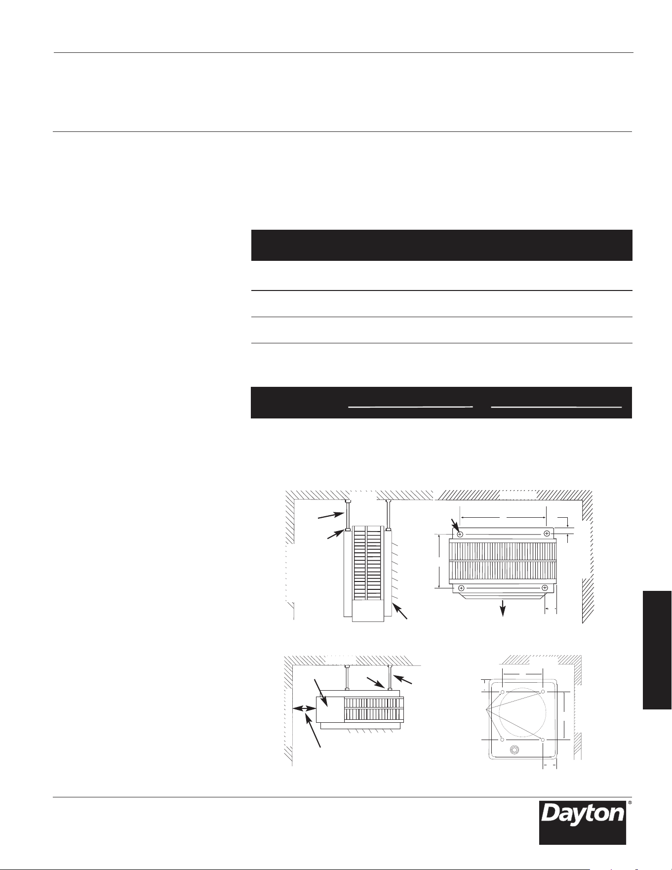
3-Fr
F
R
A
N
Ç
A
I
S
Instructions
d’installation
(suite)
8. Prévoir un dégagement de 1,5 m (5 pi)
au minimum devant le radiateur.
Se reporter au Tableau 1 pour les
exigences de dégagement sur les
côtés, le dessus et l’arrière de
l’appareil.
9. Ne pas installer de thermostat au
mercure directement sur l’appareil.
Les vibrations pourraient entraîner un
mauvais fonctionnement du radiateur.
EMPLACEMENT DU RADIATEUR
1. Installer les appareils de manière que
l’écoulement d’air ne sub
isse qu’un
minimum d’interférence de la part
des colonnes et cloisons.
2. Pour le chauffage des locaux, ne pas
diriger l’écoulement d’air vers les
occupants.
3. Les écoulements d’air doivent balayer
les murs exposés plutôt que de
souffler directement sur ceux-ci.
4. Diriger l’écoulement d’air vers le côté
d’une pièce exposé au vent lorsqu'un
appareil est installé dans un bâtiment
qui est exposé à des vents dominants.
5. Si un thermostat à distance est utilisé,
le placer ap
proximativement 1,5 m
(5 pi) au-dessus du plancher sur une
cloiso
n intérieure ou sur une colonne
à l’écart des courants d’air froid,
de sources de chaleur internes, et à
l’écart des écoulements d’air chaud
provenant de radiateurs.
6. Les grandes pièces exigent une
installation d’appareils multiples.
Installer les appareils pour produire
une circulation d’air périmétrique
pour laquelle chaque appareil
contribue réciproquement.
MONTAGE
GÉNÉRALITÉS (Voir le Tableau 3, page 4
pour les accessoires de montage)
1. Placer le radiateur de manière que
la trappe d’accès puisse être ouverte
pour accéder au compartiment
de câblage et de commande. Si le
radiateur doit être installé avec la
trappe d’accès en face d’un mur, le
radiateur doit être placé suffisamment
loin du mur pour permettre
l’ouverture complète de la trappe
(approximativement à une distance
égaleàla profondeur du radiateur).
Se reporter au Tableau 1.
Modèles 804RZ6 à 804RZ9, 804T01 à 804T22
Manuel d’utilisation et de pièces détachées Dayton
3 et 5 kW Horiz. 50,8 (2) 152,4 (6) 228,6 (9) 2YV16
Vert. 152,4 (6) 457,2 (18) 457,2 (18) 2YU84
7,5 à 10 kW Horiz. 152,4 (6) 152,4 (6) 330,2 (13) 2YV16
Vert. 152,4 (6) 609,6 (24) 609,6 (24) 2YU84
15 à 20 kW Horiz. 152,4 (6) 228,6 (9) 317,5 (12
1
/2) 2YV17
Vert. 152,4 (6) 609,6 (24) 609,6 (24) 2YU84
25 à 50 kW Horiz. 406,4 (16) 304,8 (12) 470,0 (18
1
/2) 2YU91 et 92
Vert. 304,8 (12) 914,4 (36) 914,4 (36) 2YU85
Tableau1–Dégagements par rapport au mur et au plafond, mm (pouces) /
supports de montage
Supports de
Mur Mur montage
Appareil Évacuation Plafond latéral arrière en option
3 - 5kW 5/16 po -18 154 152,4 103,2 19,1 152,4 247,7 50,8 106,4
7.5 - 10 5/16-18 154 225,4 130,2 19,1 225,4 371,5 50,8 130,2
15 - 20 5/16-18 288,9 225,4 130,2 19,1 225,4 377,8 50,8 130,2
25 - 30 3/8-16 268,3 368,3 157,2 15,9 368,3 539,8 55,6 157,2
40 - 50 3/8-16 404,8 368,3 157,2 15,9 — — — —
Table 2 – Mounting Rod Spacing
Type (Figure 2) (Figure 3)
de tige Évac. horizontale mm Évac. verticale mm
Appareil filetée A B C D E F G H
Figure 2. Montage et espacement de décharge horizontale
PLAFOND
PLAFOND
TIGE DE
MONTAGE
CONTRE-ÉCROU
AÉROTHERME
TROUS DE
MONTAGE
FILETÉS
B
A
D
C
Figure 3. Montage à décharge verticale et espacement des tiges
PORTE D'ACCES
PLAFOND
E
H
F
G
(VUE DE DESSUS)
MUR LATÉRAL
MUR LATÉRAL
MUR LATÉRAL
TIGE DE
MONTAGE (4)
CONTRE-
ÉCROU
MUR LATÉRAL
DÉGAGEMENT ÉGAL À LA LARGEUR DU
CHAUFFAGE POUR PERMETTRE L'OUVERTURE
COMPLÈTE DE LA PORTE D'ACCÈS
TROUS DE
MONTAGE
FILETÉS
(VUE DE DESSUS)
PLAFOND

4-Fr
F
R
A
N
Ç
A
I
S
Instructions
d’installation
(suite)
2. Le radiateur peut être installé pour
une évacuation verticale ou
horizontale au moyen de tiges
filetées. Se reporter au Tableau 2.
3. Des supports de montage en option
permettent la rotation horizontale du
radiateur.
4. Les louvres peuvent être positionnées
pour orienter l’air chaud dans la
direction désirée. Pour une
évacuation horizontale, les louvres
doivent orienter l’air droit devant
ou vers le bas.
MONTAGE SUR TI
GES FILETÉES
ÉVACUATION HORIZONTALE
1. Installer quatre tiges filetées dans les
trous taraudés et les fixer avec des
contre-écrous (Voir le Tableau 2.)
2. Fixer solidement les quatre tiges
filetées au plafond. (Se reporter au
Tableau 1 pour les dégagements
jusqu’au mur et jusqu’au plafond,
et au Tableau 2 pour l’espacement
des tiges filetées.)
ÉVACUATION VERTICALE
1. Enlever les boulons des trous taraudés
à l’arrière des radiateurs.
2. Installer quatre tiges filetées
dans les
trous taraudés et les fixer avec des
contre-écrous
3. Fixer solidement les quatre tiges
filetées au plafond. (Se reporter au
Tableau 1 pour les dégagements
jusqu’au mur mur et jusqu’au
plafond, et au Tableau 2 pour
l’espacement des tiges filetées.)
Radiateurs électriques à usage
industriel Dayton
®
804RZ6 à 804RZ9, 804T01 à 804T22
Manuel d’utilisation et de pièces détachées Dayton
2YU34 Kit de diffuseur radial Utiliser seulement sur des radiateurs de 7,5 à 20 kW
(804T01 à 804T04, 804T20 á 804T22, 804RZ6 á 804RZ9)
2YU83 Kit de support de montage au plafond Utiliser seulement sur des radiateurs de
pour évacuation verticale 3 et 5 kW (804T09 à 804T12, 804T16 á 804T19)
2YU84 Kit de support de montage au plafond Utiliser seulement sur des radiateurs de
pour évacuation verticale
7,5 à 20 kW
(804T01 à 804T04, 804T20 á 804T22, 804RZ6 á 804RZ9)
2YU85 Kit de support de montage au plafond Utiliser seulement sur des radiateurs de
pour évacuation verticale
25 à 50 kW
(804T06 à 804T08, 804T14, 804T15, 804T05, 804T13)
2YV16 Kit de support de montage universel Utiliser seulement sur des radiateurs de 3à10 kW
pour mur et plafond (804T09 à 804T12, 804T16 à 804T22, 804RZ6 à 804RZ8)
2YV17 Kit de support de montage universel Utiliser seulement sur des radiateurs de
pour mur et plafond 15 et 20 kW (804T01 à 804T04, 804RZ9)
2YU91 Kit de support de montage universel Utiliser seulement sur des radiateurs de
pour mur et plafond 25 kW et 30 kW (804T05 à 804T08)
2YU92 Kit de support de montage universel Utiliser seulement sur des radiateurs de
pour mur et plafond 40 kW et 50 kW (804T13 à 804T15)
2YU33 Thermostat interne unipolaire Tous les radiateurs Dayton
Plage de température 4,4 °C à 29,4 °C (40 °Fà85 °F)
2YU95 Thermostat interne à deux étages Ne peut être utilisé que sur 804T06, 804T07,
804T09, 804T10, 804T11, 804T14, 804T15
Plage de température 4,4 °C à 29,4 °C (40 °Fà85 °F)
2YU82 Interrupteur interne de ventilateur d’été Tous les radiateurs Dayton
2YU90 Thermostat de récupération de chaleur avec relais Ne peut être utilisé que sur 804T09, 804T10,
804T11, 804T18
(bobine 24 V – unipolaire normalement ouvert)
2YU93 Sectionneur d’alimentation tripolaire de 25 A; Ne peut être utilisé que sur 804T02, 804T04,
804T09, 804T10, 804T11, 804T12, 804T16, 804T17,
804T18, 804T19, 804T22, 804RZ8
25 A résistifs à 600 volts
2YU94 Sectionneur d’alimentation tripolaire de 60 A; Ne peut être utilisé que sur 804RZ9 (Lorsqu'il est câblé
pour 3 phases), 804T01, 804T04, 804T05, 804T08,
804T13, 804T21 et 804RZ7
60 A résistifs à 600 volts
Accessoires
électriques Description Remarques sur la compatibilité des produits
Accessoires
mécaniques Description Remarques sur la compatibilité des produits
Tableau 3 – Accessoires en option
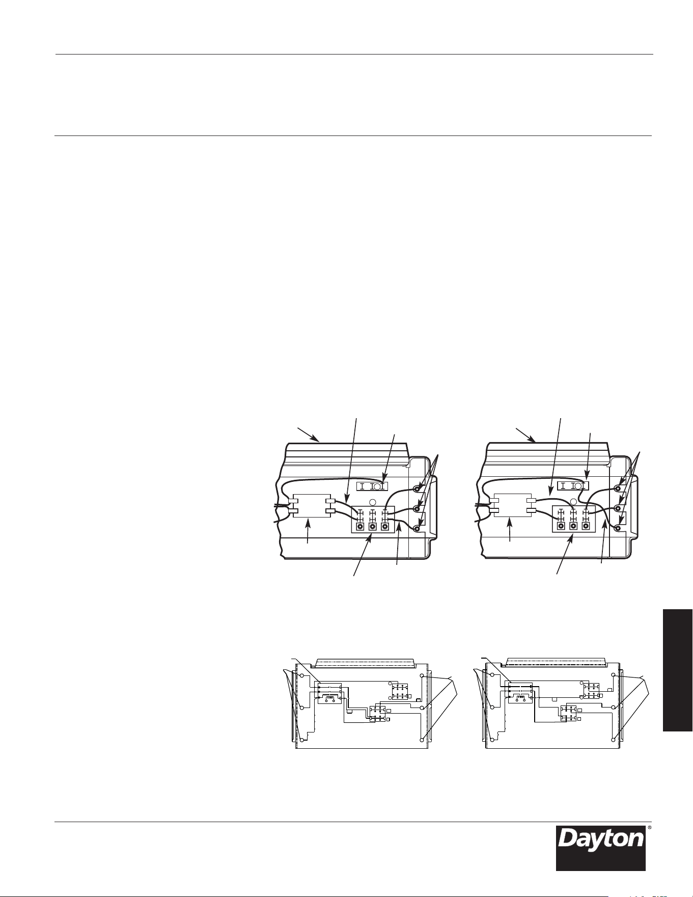
5-Fr
F
R
A
N
Ç
A
I
S
Instructions
d’installation
(suite)
CÂBLAGE
CIRCUIT DE DÉRIVATION (ALIMENTATION)
1. Connecter le radiateur uniquement
à la tension, l’ampérage et à la
fréquence spécifiés sur la plaque
signalétique.
2. Le câblage sur site doit être correcte-
ment dimensionné pour supporter
l’ampérage conformément au Code
national de l’électricité (NEC).
3. La trappe d’accès est montée
sur charnières. Une ou deux vis,
accessibles depuis le bas de la trappe,
sont à enlever p
our pouvoir l’ouvrir.
4. Une alvéole défonçable est pourvue
à l’arrière du radiateur, près de la
plaque à bornes d’alimentation.
L’alvéole défonçable de la plaque à
bornes de la commande convient à
une conduite de 12,7 mm (1/2 po).
L’alvéole défonçable de la plaque
à bornes d’alimentation comprend
de nombreux diamètres. Utiliser le
diamètre qui convient à la dimension
de conduite exigée.
5. Une borne de terre est fournie près
de la plaque à bornes d’alimentation
.
Le fil de t
erre doit être connecté
avant d’effectuer toute autre
connexion.
6. La plaque à bornes d’alimentation
est équipée de borniers dimensionnés
pour accepter des fils d’alimentation
de dimension correcte. Des fils de
capacité nominale de 600 V et de
60 °C sont suffisants pour le circuit
de dérivation du radiateur. Le fil
d’aluminium ou de cuivre est
acceptable pour les borniers de la
plaque à bornes d’alimentation.
Le fil de cuivre est recommandé.
7. Chaque radiateur dispose d
’un
schéma de câblage apposé à
l’intérieur de la trappe d’accès.
Consulter ce schéma avant
d’effectuer toute connexion sur site.
REMARQUE IMPORTANTE : Couple
d’installation des vis de languette –
durant le transport il est possible que
les connexions de languettes à vis se
desserrent. Après l’installation et avant
indiqué dans le schéma de câblage
fixé au radiateur.
8. Une connexion monophasée ou
triphasée peut être utilisée avec les
modèles de radiateur 804T16, 804T17,
804T20, 804T21, 804RZ6, 804RZ7, et
804RZ9. Ces appareils sont câblés
en usine pour un fon
ctionnement
monophasé. Si ces radiateurs doivent
être utilisés avec une alimentation
triphasée, reconnecter les fils comme
a. Des informations supplémentaires
peuvent être trouvées en observant
les schémas de câblage Figure 4a à
traverse 4b et en suivant les directives
du paragraphe « Câblage de la
commande ».
Modèles 804RZ6 à 804RZ9, 804T01 à 804T22
Manuel d’utilisation et de pièces détachées Dayton
Figure 4a – Connexions de câblage pour alimentation monophasée et triphasée
(804T16, 804T17, 804T20, 804T21)
A
B
Face avant
du radiateur
Éléments
chauffants
Conducteur « A1 »
Bornier triphasé
Conducteur « B1 »
Bornier
d’alimentation
Contacteur (ou P2)
Vers les éléments chauffants
Câblé sur site pour
alimentation triphasée
A
B
Face avant
du radiateur
Conducteur«A1 »
Bornier triphasé
Éléments
chauffants
Conducteur«B1 »
Bornier
d’alimentation
Contacteur (ou P2)
Vers les éléments chauffants
Câbl
Alternative triphaséeAlternative monophasée
é en usine pour
alimentation monophasée
Figure 4b – Connexions de câblage pour alimentation monophasée et
triphasée (804RZ6 et 804RZ7)
d’allumer le dispositif de chauffage,
vérifiez le serrement approprié au
couple minimal recommandé de toutes
les vis à fixation selon l’étiquette
apposée sur l’appareil.
b. Sur les modèles 804T16, 804T17,
804T20, 804T21, 804RZ6 et 804RZ7
(Figures 4a et 4b), déplacer seule-
ment les
deux fils marqués « A1 »
et
« B1»;
ne déplacer ni changer
aucun autrecâblage. Le conducteur
d’élément chauffant marqué « B1
», qui
est câblé en usine au bornier
d’alimentation doit être déplacé à
la
borne «B»du bornier triphasé.
(3) ÉLÉMENTS
CONTACTEUR
BORNIER DE PUISSANCE
L2
A1
L3
L1
B1
(3) ÉLÉMENTS
A
B
1
2
3
(3) ÉLÉMENTS
(3) ÉLÉMENTS
CONTACTEUR
BORNIER DE PUISSANCE
A
L2
L3
A1
C
B
A
L1
B1
B
1
2
3
1
2
3
BLOC
3 PHASES
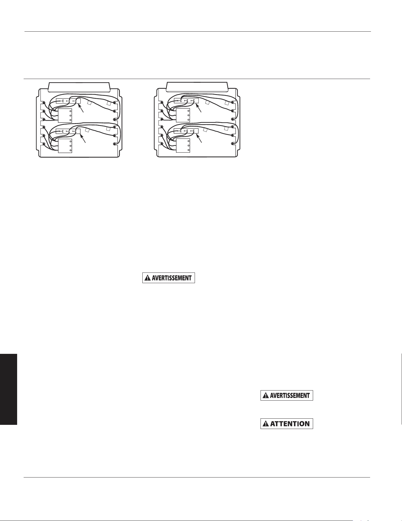
6-Fr
F
R
A
N
Ç
A
I
S
Instructions
d’installation
(suite)
d. Le modèle 804RZ9 (Figure 4b)
dispose de deux borniers triphasés
placés à côté des relais (contacteurs).
Déplacer seulement les deux fils
marqués « C1 » et « D1 » sur chacun
de ces deux b
orniers triphasés au
bornier « B ». Ne pas déplacer ni
changer aucun autre fil.
9. Les accessoires
électriques, soit en
kits soit en options installées en
usine, apparaissent connectés par
une ligne en tirets sur le schéma
de câblage du radiateur.
10. RADIATEUR 208/240 VOLTS. Les
radiateurs sont câblés pour 240 V
en usine. Si le radiateur doit être
connecté sur une alimentation 208 V,
les conducteurs du transformateur
doivent être intervertis. Pour le
modèle 804T14, intervertir les
conducteurs ORANGE et ROUGE sur
le primaire. Le conducteur noir est le
COMMUN pour le tra
nsformateur de
50 VA fourni avec ce modèle. Pour
les autres modèles, intervertir les
conducteurs NOIR et ROUGE sur le
primaire. Le conducteur BLANC est
le COMMUN pour le transformateur
commande de 40 VA fourni avec ces
radiateurs. Toujours se reporter au
schéma de câblage sur le couvercle
du radiateur avant d'effectuer cette
reconnexion des fils du primaire du
transformateur.
CÂBLAGE DE LA COMMAN
DE
La tension secteur
est présente sur
quelques bornes de la plaque à bornes
de commande. Pour éviter tout danger,
toujours débrancher l’alimentation
électrique du radiateur avant
d’effectuer quelque connexion que
ce soit sur le circuit de commande.
1. Pour le câblage du circuit de
commande, utiliser du fil isolé
prévu au minimum pour 600 V et
de classe 1 CNE.
2. Utiliser des cosses sertissables à
fourche aux extrémités des fils qui
se connectent à la plaque à bornes
de commande si plus d’une connexion
doit être réalisée sous une vis de
borne.
3. Pour le
s appareils non livrés avec un
contacteur intégré (3 kW), se reporter
au schéma de câblage de la Figure 5,
page 8.
REMARQUE : Le thermostat et le
câblage du circuit de commande
doivent être capables de supporter la
pleine charge du radiateur (par exemple
le courant nominal du 804T09 est de
24 A).
4. Pour les appareils livrés avec un
contacteur intégré (appareils de
5 kW et plus), se repo
rter au schéma
de câblage de la Figure 6, page 8. Le
câblage du circuit de commande doit
être au mini
mum de calibre 18 AWG.
Instructions
d’utilisation
1. Le radiateur doit être correctement
installé avant son utilisation.
2. Mettre le radiateur sous tension
« ON » au niveau du panneau de
service principal.
3. Le cas échéant, se reporter aux
instructions des accessoires de
commande en ce qui concerne
l’utilisation correcte de toute
commande ou accessoires utilisés
avec le radiateur.
RÉINITIALISATION DE LA
COMMANDE ANTISURCHAUFFE
DE SÉCURITÉ (OPTION INSTALLÉE
EN USIN
E SEULEMENT)
Le limiteur thermique est placé à
l’intérieur à l’arrière du radiateur.
Sur les modèles 3 kW et 5 kW, l’accès
au bouton de réenclenchement est
sur le côté droit (lorsque l’on fait face
à l’arrière du radiateur). Sur tous les
autres modèles l’accès est près du
dessus à l’arrière du radiateur.
Le limiteur à réenclenchement manuel
est monté en série avec la protection
à recyclage automatique (limiteur). Le
limiteur à réenclenchement manuel ne
se réinitialise pas t
ant que le radiateur
n’est pas refroidi et que le bouton
n’est pas enfoncé.
Ne pas modifier
ni court-circuiter
aucun dispositif de limitation thermique
de sécurité à l’intérieur du radiateur.
Ne pas essayer
d'utiliser le
radiateur si la commande de sécurité
se déclenche constamment après avoir
été réinitialisée. Une telle utilisation
risque d'endommager le radiateur
irréversiblement, de déclencher un
incendie ou de compromettre la
sécurité.
Radiateurs électriques à usage
industriel Dayton
®
804RZ6 à 804RZ9, 804T01 à 804T22
Manuel d’utilisation et de pièces détachées Dayton
Figure 4c – Connexions de câblage pour alimentation monophasée et
triphasée (804RZ9)
B
C
1
D
1
D
1
C
1
C
D
B
C
D
Bornier triphasé
Bornier triphasé
B
C
1
D
1
D
1
C
1
C
D
B
C
D
Bornier triphasé
Bornier triphasé
Câblé sur site pour
alimentation triphasée
Câblé en usine pour
alimentation monophasée
c. Pour 804RZ6 et 804RZ7, le fil « A1 »
doit être déplacé du bornier de
puissance à la borne « A » du bornier
triphasé. Pour 804T16, 804T17, 804T20,
et 804T21, le fil « A1 » doit être
déplacé vers la borne « A » (milieu)
du bornier d'alimentation.
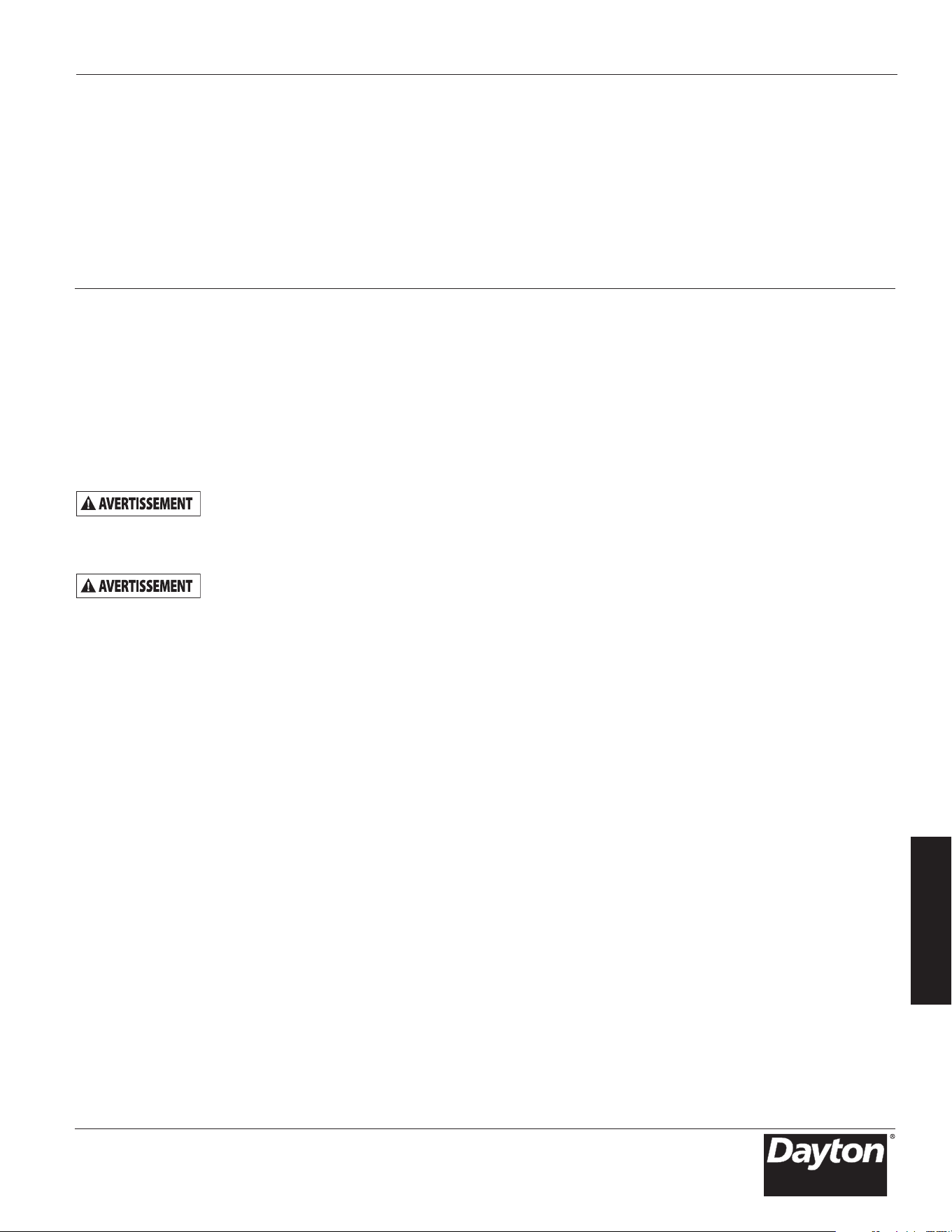
Instructions
d’entretien
Il est important de garder le radiateur
propre. Ce radiateur est conçu pour
fonctionner et tenir chaud pendant des
années grâce à un entretien minimal.
Afin d’assurer un fonctionnement
efficace, suivre les instructions
simples ci-après.
Tout entretien
nécessitant,
au-delà d’un nettoyage simple, de
démonter l'appareil, doit être effectué
par du personnel d’entretien agréé.
Afin de réduire le
risque d'incendie,
de choc électrique ou de blessure,
débrancher l’alimentation électrique
du radiateur au niveau du panneau de
service principal et vérifier que l’élément
chauffant est froid avant d’effectuer
une réparation ou un entretien.
INSTRUCTIONS DE NETTOYAGE À
L’INTENTION DE L’UTILISATEUR
1. Lorsque le radiateur a refroidi, un
aspirateur équipé d'une brosse peut
être utilisé pour enlever la poussière
ou les peluches accumulées sur les
surfaces extérieures du radiateur, y
compris sur les ouve
rtures de la grille.
2. Essuyer la poussière ou les peluches
accumulées sur la grille et les surfaces
extérieures au moyen d'un chiffon
humide.
3. Remettre le radiateur sous tension
et vérifier qu’il fonctionne
correctement.
INSTRUCTIONS DE NETTOYAGE
D’ENTRETIEN
(Le nettoyage d’entretien ne
doit être effectué que par du
personnel d’entretien agréé)
Le radiateur doit faire l'objet d'un
nettoyage et d'un entretien par
du personnel d'entretien agréé au
moins une fois pa
r an afin d'assurer
un fonctionnement efficace et sûr.
Cet entretien comprend la dépose de
la grille et, si nécessaire, la dépose
du radiateur du boîtier arrière afin
de nettoyer tout résidu provenant
de l'appareil. Lorsque le nettoyage
et l’entretien ont été effectués,
le radiateur doit être remonté
entièrement pour vérifier qu'il
fonctionne correctement.
7-Fr
F
R
A
N
Ç
A
I
S
Modèles 804RZ6 à 804RZ9, 804T01 à 804T22
Manuel d’utilisation et de pièces détachées Dayton
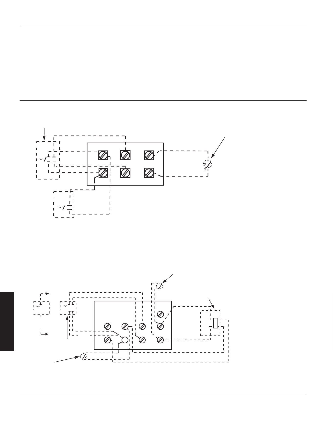
Figure 6 – Plaque à bornes de commande (pour radiateurs avec contacteurs)
REMARQUES : (Voir le
tableau 3, page 4 pour les
accessoires électriques)
1. Ce type de plaque à bornes
de commande est utilisé
sauf sur les modèles 804T09,
804T10, et 804T11.
2. Enlever le cavalier W1 vers
W2 quand un thermostat
à 2 étages est utilisé.
3. Seulement un interrupteur
de ventilateur et un
thermostat accessoire
peuvent être installés
dans un radiateur simple.
4. Les thermostats sous tension
de ligne externe doivent
être traités comme étant
seulement à simple étage.
T
T
MT-1
MT-2
BLACK TO W1
RED TO R
BLACK
RED
RED
BLACK
C
R W1
W2
F2
F1
G
TR
T
S
FAN RELAY
(FOR MRFS-2 AMD MHRT)
2YU33
2YU95
Thermostat interne
à 1 étage
Interrupteur de
thermostat de
récupération de
chaleur 2YU90 (Interne)
Thermostat interne
à 2 étages
Accessoire pour
interrupteur de ventilateur
d’été 2YU82 (Interne)
Accessoire de relais de
thermostat de récupération
de chaleur 2YU90 (Interne)
MT-1
MT-2
BLACK
RED
RED
BLACK
P2
H2
F1
F2
S
P1
H1
2YU95
2YU 33
Figure 5 – Plaque à bornes de commande (pour radiateurs sans contacteur)
REMARQUES : (Voir le tableau 3,
page 4 pour les accessoires électriques)
1. Ce type de plaque à bornes de
commande est utilisé sur les modèles
804T09, 804T10, 804T11, et 804T18.
2. Quand l’appareil est câblé en
monophasé, placer le cavalier de H1
à H2. Si un thermostat unipolaire est
utilisé avec un appareil monophasé,
connecter les conducteurs du
thermostat aux bornes P1 et H1
3. Les thermostats sous tension de
ligne externe doivent être traités
comme étant seulement à
simple étag
e.
Thermostat
interne à
1 étage
Thermostat interne à 2 étages
Accessoire pour interrupteur de
ventilateur d’été 2YU82 (Interne)
Accessoires de câblage
Rouge
Noir
Rouge
Noir
Rouge
Noir
Rouge
Noir
Rouge à R
Noir
to W1
8-Fr
F
R
A
N
Ç
A
I
S
Radiateurs électriques à usage
industriel Dayton
®
Manuel d’utilisation et de pièces détachées Dayton
804RZ6 à 804RZ9, 804T01 à 804T22
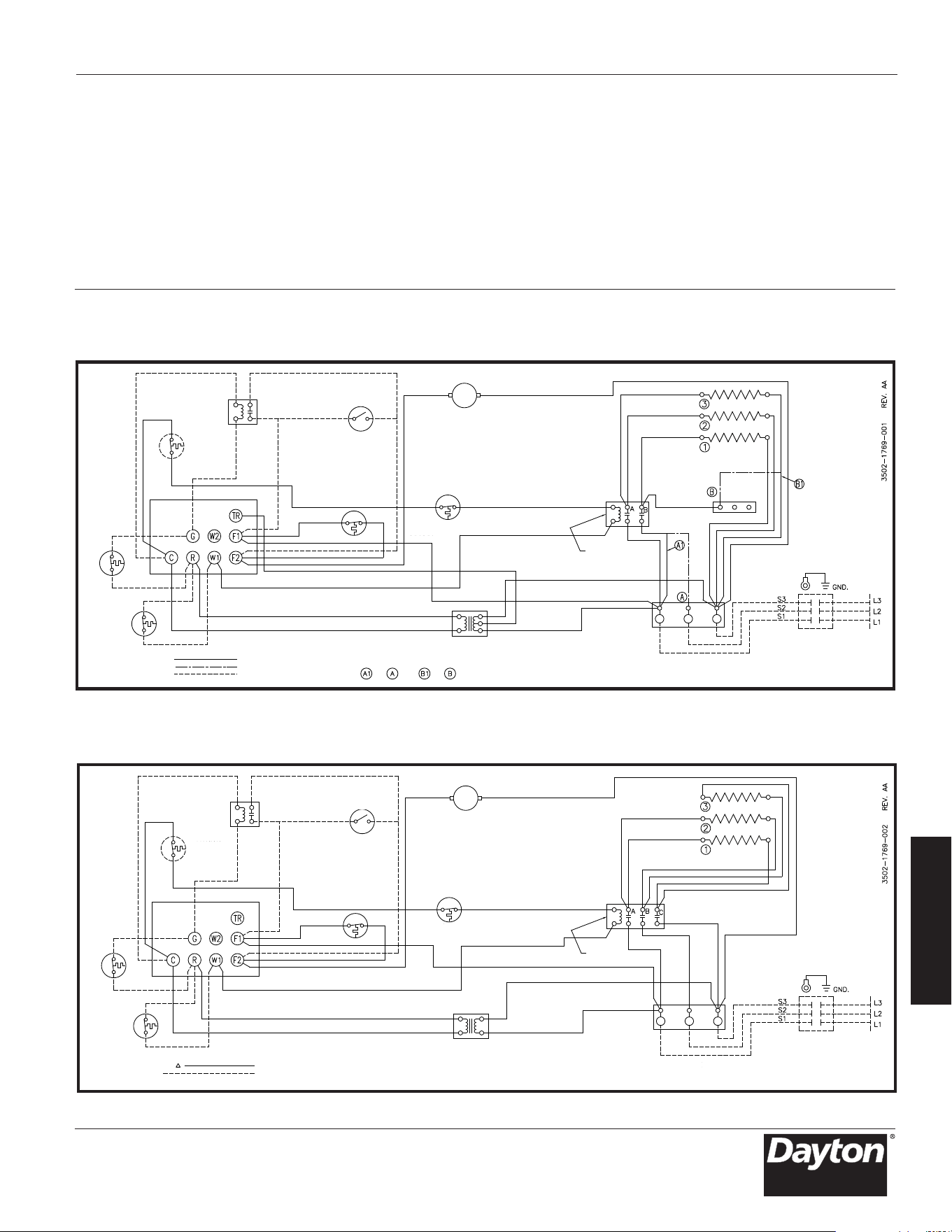
Schémas de câblage
Diagramme 1: 3 éléments, monophasé et triphasé (des modèl 804T21)
RELAIS
VENTILATEUR
LIMITE DE
RÉINITIALI-
SATION
MANUELLE
INTERRUPTEUR
DE VENTILATEUR
D'ÉTÉ
LIMITE DE
SURCHAUFFE
RETARD
VENTILATEUR
CARTE
BORNE DE
CONTRÔLE
THERMOSTAT DE
RÉCUPÉRATION
DE
CHALEUR
THERMOSTAT
TRANSFORMATEUR
ROUGE
MOTEUR
ÉLÉMENT ARRIÈRE
ÉLÉMENTS
BLOC
TERMINAL
3 PHASES
LE CÂBLAGE DU
CIRCUIT DE CONTRÔLE
DOIT ÊTRE NEC CLASSE
1 ADAPTÉ À 600 V
INTERRUPTEUR DE
DÉCONNEXION
D'ALIMENTATION
BLOC DE BORNES
D'ALIMENTATION À UTILISER
UNIQUEMENT AVEC DES
CONDUCTEURS EN CUIVRE
UTILISEZ L1 ET L3 POUR
LES CONNEXIONS MONOPHASÉES
BLANC
1 PHASE CONNECTÉE
3 PHASE CONNECTÉE
ÉQUIPEMENT OPTIONEL
INSTALLÉ SUR LE TERRAIN
À À
ET
CONTACTEUR
CÂBLÉ D'USINE 1 PHASE
POUR CONNEXION EN 3 PHASES
NOIR
Diagramme 2: 3 éléments, 3 phases (des modèles 804T12, 804T19, 804T22 et 804RZ8)
RELAIS
VENTILATEUR
LIMITE DE
RÉINITIALI-
SATION
MANUELLE
INTERRUPTEUR
DE VENTILATEUR
D'ÉTÉ
RETARD
VENTILATEUR
CARTE
BORNE DE
CONTRÔLE
THERMOSTAT DE
RÉCUPÉRATION
DE
CHALEUR
TERMOSTATO
ÉLÉMENT ARRIÈRE
ÉLÉMENTS
LE CÂBLAGE DU
CIRCUIT DE CONTRÔLE
DOIT ÊTRE NEC CLASSE
1 ADAPTÉ À 600 V
INTERRUPTEUR DE
DÉCONNEXION
D'ALIMENTATION
BLOC DE BORNES
D'ALIMENTATION À UTILISER
UNIQUEMENT AVEC DES
CONDUCTEURS EN CUIVRE.
LIMITE DE
SURCHAUFFE
TRANSFORMATEUR
USINE FILAIRE 3 PHASE
ÉQUIPEMENT EN
OPTION INSTALLÉ SUR LE TERRAIN
CONTACTEUR
MOTEUR
NOIR
9-Fr
F
R
A
N
Ç
A
I
S
Modèles 804RZ6 à 804RZ9, 804T01 à 804T22
Manuel d’utilisation et de pièces détachées Dayton
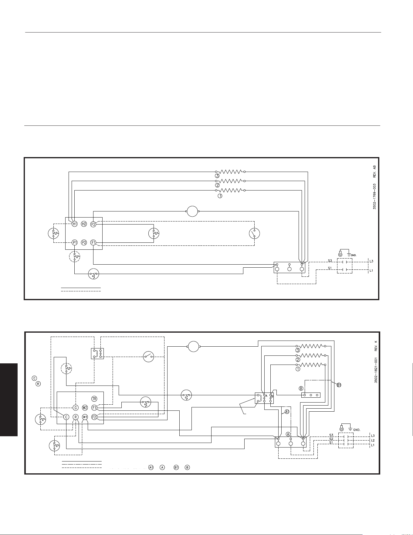
Diagramme 3: 3 éléments, monophasé (des modèles 804T09, 804T10, 804T11 et 804T18)
ÉLÉMENT ARRIÈRE
ÉLÉMENTS
THERMOSTAT
RETARD
VENTILATEUR
INTERRUPTEUR
DE VENTILATEUR
D'ÉTÉ
LÍMITE DE
RESET
MANUAL
LIMITE DE
SURCHAUFFE
CÂBLAGE D'USINE
ÉQUIPEMENT EN OPTION
INSTALLÉ SUR LE TERRAIN
BLOQUE DE TERMINALES DE
ALIMENTACIÓN PARA USO
ÚNICAMENTE CON
CONDUCTORES DE COBRE.
INTERRUPTEUR DE
DÉCONNEXION
D'ALIMENTATION
LE CÂBLAGE DU
CIRCUIT DE CONTRÔLE
DOIT ÊTRE NEC CLASSE
1 ADAPTÉ À 600 V
CARTE BORNE
DE CONTRÔLE
MOTEUR
Diagramme 4: 3 éléments, monophasé et triphaséia ra (des modèles 804T16, 804T17)
ÉLÉMENT ARRIÈRE
ÉLÉMENTS
THERMOSTAT
RETARD
VENTILATEUR
INTERRUPTEUR
DE VENTILATEUR
D'ÉTÉ
LIMITE
DE SURCHAUFFE
INTERRUPTEUR DE
DÉCONNEXION
D'ALIMENTATION
LE CÂBLAGE DU
CIRCUIT DE CONTRÔLE
DOIT ÊTRE NEC CLASSE
1 ADAPTÉ À 600 V
BLOC
TERMINAL
3 PHASES
UTILISEZ L1 ET L3 POUR LES
CONNEXIONS MONOPHASÉES
CÂBLÉ D'USINE 1 PHASE
POUR 3 PHASES, CONNECTER
À ÀET
TENSION DE CONTRÔLE INTERNE UNIQUEMENT
THERMOSTAT DE
RÉCUPÉRATION
DE
CHALEUR
TABLERO DE
TERMINALES
DE CONTROL
1 PHASE CONNECTÉE
3 PHASE CONNECTÉE
ÉQUIPEMENT EN OPTION
INSTALLÉ SUR LE TERRAIN
LÍMITE DE
RESET
MANUAL
MOTEUR
CONNECTER LA
TENSION
EXTERNE
À
ET
BLOC DE BORNES
D'ALIMENTATION À UTILISER AVEC
LES CONDUCTEURS AI ET Cu
CONTACTEUR
RELAIS
VENTILATEUR
F
R
A
N
Ç
A
I
S
Radiateurs électriques à usage
industriel Dayton
®
804RZ6 à 804RZ9, 804T01 à 804T22
Manuel d’utilisation et de pièces détachées Dayton
10-Fr
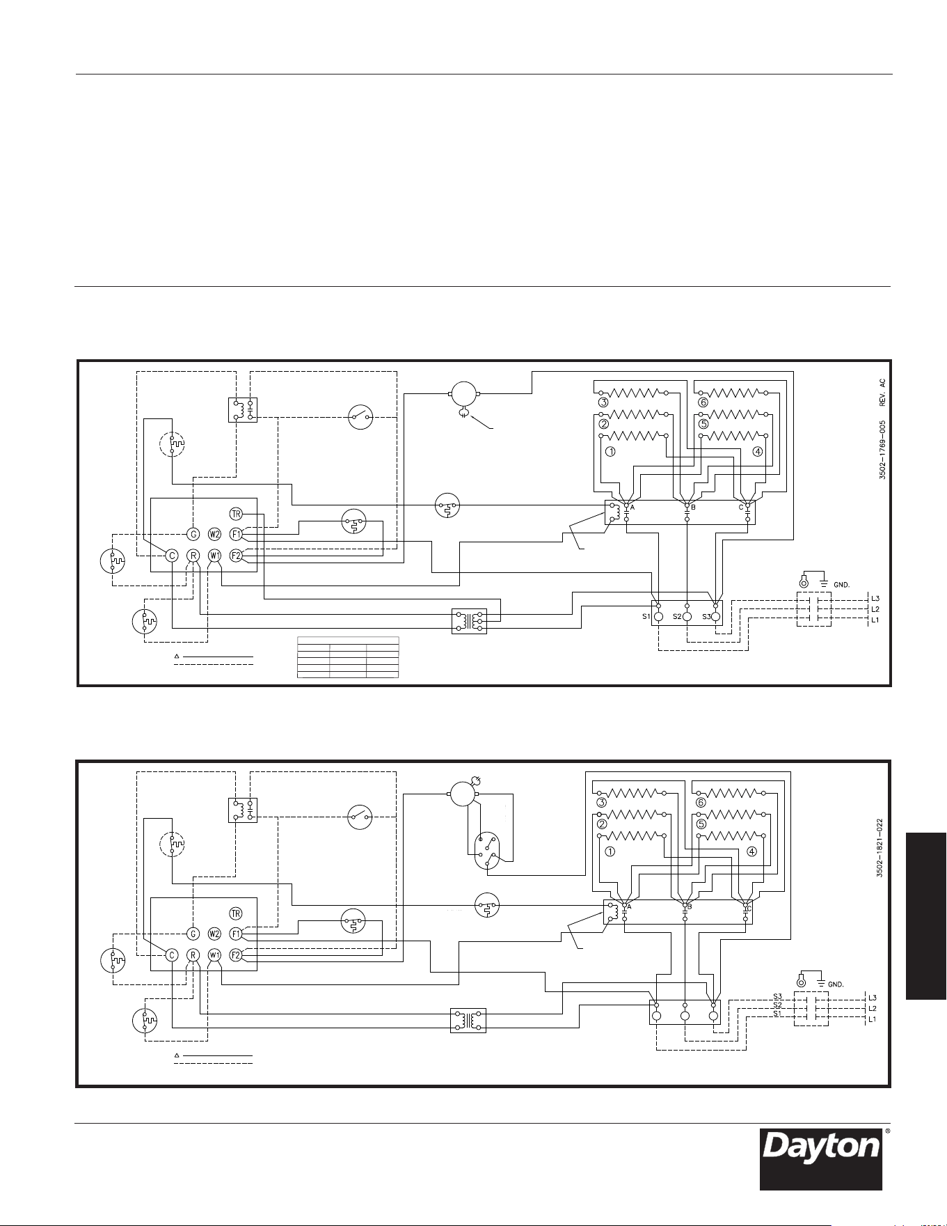
Schémas de câblage (suite)
Diagramme 5: 6 éléments, 3 phases (des modèles 804T01, 804T02, 804T03 et 804T04)
RELAIS
VENTILATEUR
INTERRUPTEUR
DE VENTILATEUR
D'ÉTÉ
LIMITE DE
RÉINITIALI-
SATION
MANUELLE
RETARD
VENTILATEUR
CONDENSATEUR
AU BESOIN
MARRONMARRON
THERMOSTAT DE
RÉCUPÉRATION
DE
CHALEUR
THERMOSTAT
LIMITE
DE SURCHAUFFE
JAUNE
JAUNE
TRANSFORMATEUR
BLANC
FIL 1
FIL 2
TABLEAU DES FILS DU XFMR
TENSION FIL 1 FIL 2
208V NOIRE ROUGE
277V ROUGE NOIRE
277V PAS DE FIL VIOLET
480V PAS DE FIL NOIRE
CARTE
BORNE DE
CONTRÔLE
ÉLÉMENT ARRIÈRE
ÉLÉMENTSÉLÉMENTS
LE CÂBLAGE DU
CIRCUIT DE CONTRÔLE
DOIT ÊTRE NEC CLASSE
1 ADAPTÉ À 600 V
INTERRUPTEUR DE
DÉCONNEXION
D'ALIMENTATION
BLOC DE TERMINAL D'ALIMENTATION
À UTILISER UNIQUEMENT AVEC DES
CONDUCTEURS EN CUIVRE
MOTEUR
USINE FILAIRE 3 PHASE
ÉQUIPEMENT EN OPTION
INSTALLÉ SUR LE TERRAIN
CONTACTEUR
Diagramme 6: 6 éléments, 6 phases (des modèles 804T05 et 804T08)
RELAIS
VENTILATEUR
INTERRUPTEUR
DE VENTILATEUR
D'ÉTÉ
LIMITE DE
RÉINITIALI-
SATION
MANUELLE
RETARD
VENTILATEUR
COMMUTATEUR
DE VITESSE
MARRON
ORG
BLANC
ROUGE
BLEUE
NOIRE
ROUGE
THERMOSTAT DE
RÉCUPÉRATION
DE
CHALEUR
THERMOSTAT
LIMITE
DE SURCHAUFFE
TRANSFORMATEUR
CARTE
BORNE DE
CONTRÔLE
ÉLÉMENT ARRIÈRE
REV. C
ÉLÉMENTSÉLÉMENTS
LE CÂBLAGE DU
CIRCUIT DE CONTRÔLE
DOIT ÊTRE NEC CLASSE
1 ADAPTÉ À 600 V
INTERRUPTEUR DE
DÉCONNEXION
D'ALIMENTATION
BLOC DE TERMINAL D'ALIMENTATION
À UTILISER UNIQUEMENT AVEC DES
CONDUCTEURS EN CUIVRE
USINE FILAIRE 3 PHASE
ÉQUIPEMENT EN OPTION
INSTALLÉ SUR LE TERRAIN
CONTACTEUR
MOTEUR
11-Fr
F
R
A
N
Ç
A
I
S
Modèles 804RZ6 à 804RZ9, 804T01 à 804T22
Manuel d’utilisation et de pièces détachées Dayton
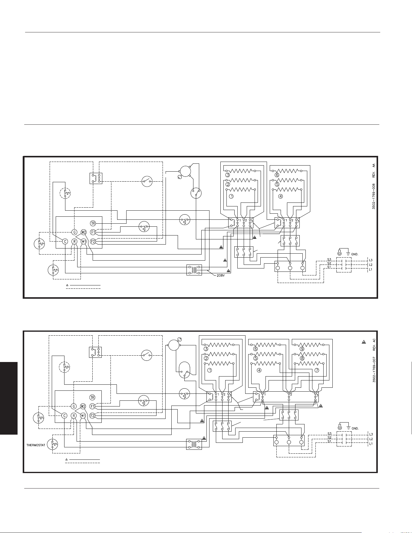
Schémas de câblage (suite)
Diagramme 7: 6 éléments, 2 entrepreneurs, 3 phases (modèle 804T07)
ÉLÉMENT ARRIÈRE
ÉLÉMENTSÉLÉMENTS
MARRON
MARRON
BLANC
NOIR
ROUGE
ROUGE
COMMUTATEUR
DE VITESSE
INTERRUPTEUR
DE VENTILATEUR
D'ÉTÉ
RELAIS
VENTILATEUR
LIMITE DE
RÉINITIALI-
SATION
MANUELLE
THERMOSTAT DE
RÉCUPÉRATION
DE
CHALEUR
THERMOSTAT
RETARD
VENTILATEUR
LIMITE
DE SURCHAUFFE
TRANSFORMATEUR
NOIR
UNIQUEMENT
BLOC FUSIBLE
SI NÉCESSAIRE
LE CÂBLAGE DU
CIRCUIT DE CONTRÔLE
DOIT ÊTRE NEC CLASSE
1 ADAPTÉ À 600 V
INTERRUPTEUR DE
DÉCONNEXION
D'ALIMENTATION
BLOC DE BORNES D'ALIMENTATION
À UTILISER UNIQUEMENT AVEC DES
CONDUCTEURS EN CUIVRE
MOTEUR
CONTACTEUR
CARTE
BORNE DE
CONTRÔLE
USINE FILAIRE 3 PHASE
ÉQUIPEMENT EN OPTION
INSTALLÉ SUR LE TERRAIN
Diagramme 8: 9 éléments, 2 entrepreneurs, 3 phases
(des modèles 804T13 et 804T15)
INTERRUPTEUR
DE VENTILATEUR
D'ÉTÉ
BLOC FUSIBLE
SI NÉCESSAIRE
LE CÂBLAGE DU
CIRCUIT DE CONTRÔLE
DOIT ÊTRE NEC CLASSE
1 ADAPTÉ À 600 V
INTERRUPTEUR DE
DÉCONNEXION
D'ALIMENTATION
BLOC DE BORNES D'ALIMENTATION
À UTILISER UNIQUEMENT AVEC DES
CONDUCTEURS EN CUIVRE
CONTACTEUR
MARRON
MARRON
MOTEUR
ROUGE
NOIR
ÉLÉMENTS ÉLÉMENTS ÉLÉMENTS
ÉLÉMENT ARRIÈRE
COMMU-
TATEUR
DE VITESSE
TRANSFORMATEUR
CARTE
BORNE DE
CONTRÔLE
THERMOSTAT DE
RÉCUPÉRATION
DE
CHALEUR
USINE FILAIRE 3 PHASE
ÉQUIPEMENT EN OPTION
INSTALLÉ SUR LE TERRAIN
RELAIS
VENTILATEUR
RETARD
VENTILATEUR
LIMITE DE
RÉINITIALI-
SATION
MANUELLE
LIMITE
DE SURCHAUFFE
12-Fr
F
R
A
N
Ç
A
I
S
Radiateurs électriques à usage
industriel Dayton
®
804RZ6 à 804RZ9, 804T01 à 804T22
Manuel d’utilisation et de pièces détachées Dayton
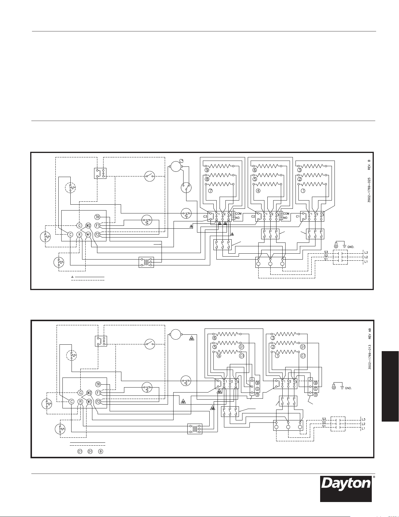
Schémas de câblage (suite)
Diagramme 9: 9 éléments, 3 entrepreneurs, 3 phases (modèle 804T14)
ORANGE
(208V UNIQUEMENT)
ROUGE
ROUGE
NOIR
BLANC
NOIR
RELAIS
VENTILATEUR
INTERRUPTEUR
DE VENTILATEUR
D'ÉTÉ
CARTE
BORNE DE
CONTRÔLE
LIMITE DE
RÉINITIALI-
SATION
MANUELLE
THERMOSTAT DE
RÉCUPÉRATION
DE
CHALEUR
THERMOSTAT
RETARD
VENTILATEUR
COMMU-
TATEUR
DE VITESSE
LIMITE DE
SURCHAUFFE
TRANSFORMATEUR
MARRON
MARRON
ÉLÉMENTS ÉLÉMENTS ÉLÉMENTS
ÉLÉMENT ARRIÈRE
INTERRUPTEUR AUX
BLOC DE
FUSIBLE
BLOC DE
FUSIBLE
INTERRUPTEUR AUX
BLOC DE BORNES D'ALIMENTATION À UTILISER
UNIQUEMENT AVEC DES CONDUCTEURS EN CUIVRE
LE CÂBLAGE DU
CIRCUIT DE CONTRÔLE
DOIT ÊTRE NEC CLASSE
1 ADAPTÉ À 600 V
INTERRUPTEUR DE
DÉCONNEXION
D'ALIMENTATION
MOTEUR
USINE FILAIRE 3 PHASE
ÉQUIPEMENT EN OPTION
INSTALLÉ SUR LE TERRAIN
Diagramme 10: 6 éléments, monophasé et triphasé (des modèle 804RZ9)
BLANC
ROUGE
NOIR
BLOC TERM.
3 PHASES
BLOC DE BORNES D'ALIMENTATION
À UTILISER UNIQUEMENT AVEC
DES CONDUCTEURS EN CUIVRE
UTILISER L1 ET L3 POUR
LES CONNEXIONS MONOPHASÉES
RELAIS
VENTILATEUR
INTERRUPTEUR
DE VENTILATEUR
D'ÉTÉ
LIMITE DE
RÉINITIALI-
SATION
MANUELLE
RETARD
VENTILATEUR
THERMOSTAT
TRANSFORMATEUR
LIMITE
DE SURCHAUFFE
ÉLÉMENTS ÉLÉMENTS
ÉLÉMENT ARRIÈRE
INTERRUPTEUR
DE DÉCONNEXION
D'ALIMENTATION
LE CÂBLAGE DU
CIRCUIT DE CONTRÔLE
DOIT ÊTRE NEC CLASSE
1 ADAPTÉ À 600 V
BLOC TERM.
3 PHASES
SWITCH POUR 3 PHASE UNIQUEMENT
THERMOSTAT DE
RÉCUPÉRATION
DE
CHALEUR
MOTEUR
CARTE
BORNE DE
CONTRÔLE
MONOPHASE CONNECTÉ
ÉQUIPEMENT EN OPTION
INSTALLÉ SUR LE TERRAIN
POUR 3 PHASES, CONNECTER ET AU TERM., CHAQUE BLOC DE PHASE
BLOC
FUSIBLE SI
NÉCESSAIRE
13-Fr
F
R
A
N
Ç
A
I
S
Modèles 804RZ6 à 804RZ9, 804T01 à 804T22
Manuel d’utilisation et de pièces détachées Dayton
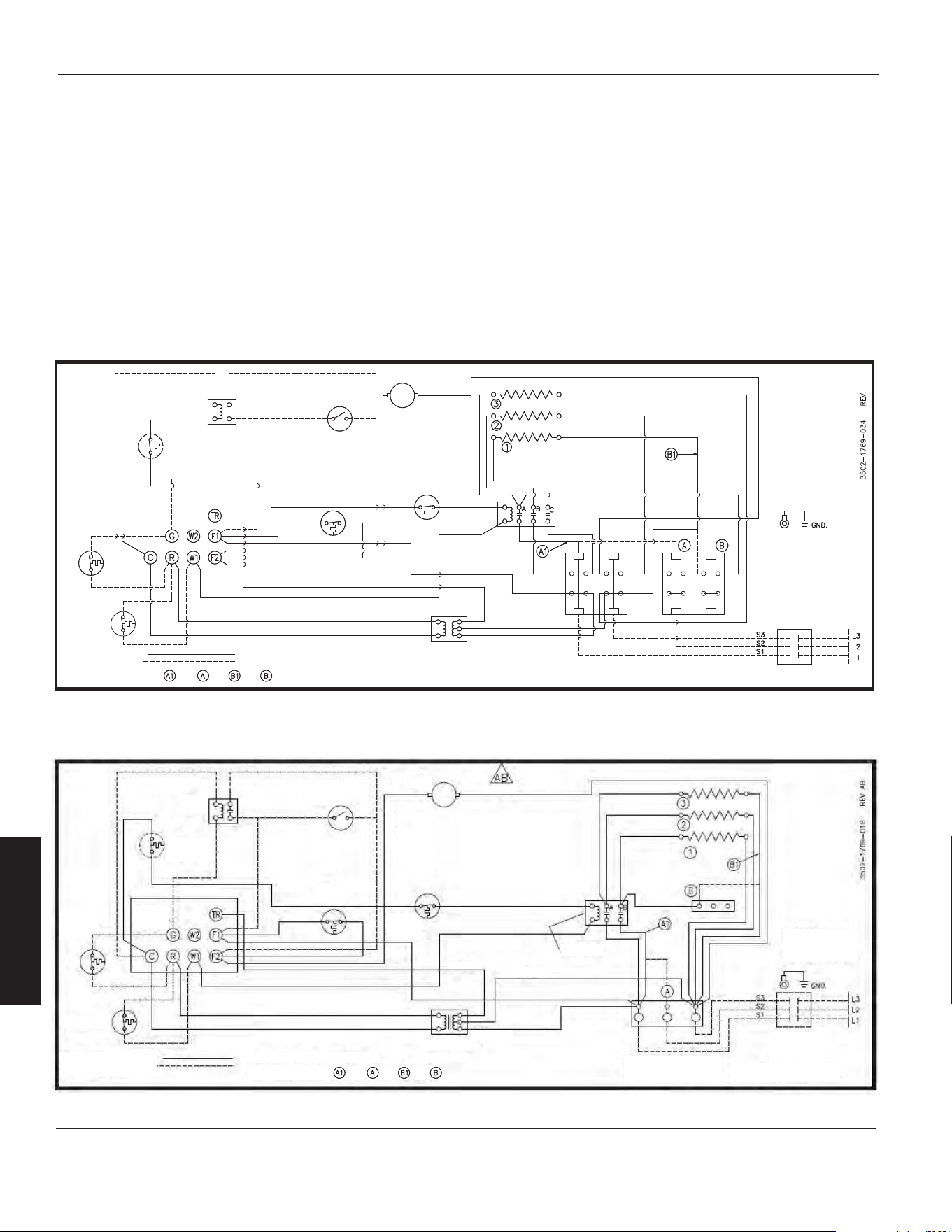
Schémas de câblage (suite)
Diagramme 11: 3 éléments, monophasé et triphasé (modèle 804RZ6)
LIMITE DE
RÉINITIALI-
SATION
MANUELLE
THERMOSTAT DE
RÉCUPÉRATION DE
CHALEUR
INTERRUPTEUR
DE VENTIL
D'ÉTÉ
MOTEUR
ÉLÉMENTS
CARTE
BORNE DE
CONTRÔLE
LIMITE DE
SURCHAUFFE
RELAIS
VENTILATEUR
NOIR
ROUGE
BLANC
TRANSFORMATEUR
CONNECTÉ EN MONOPHASÉ
ÉQUIPEMENT OPTIONAL
TERM.FIELS INSTALLEDPOURPOUR ET
TERMOSTAT
CE BLOC RÉSIDE LE PLUS PRÈS
DES BORNES DE L'ÉLÉMENT
LE CÂBLAGE DU CIRCUIT
DE CONTRÔLE DOIT ÊTRE
NEC CLASSE 1 ADAPTÉ
À 600 V
SWITCH POUR 3 PHASE
UNIQUEMENT
INTERRUPTEUR
D'ALIMENTATION
UTILISEZ L1 ET L3 POUR LES
CONNEXIONS MONOPHASÉES
BLOC DE TERMINA D'ALIMENTATION
À UTILISER UNIQUEMENT AVEC DES
CONDUCTEURS EN CUIVRE.
14-Fr
F
R
A
N
Ç
A
I
S
Radiateurs électriques à usage
industriel Dayton
®
804RZ6 à 804RZ9, 804T01 à 804T22
Manuel d’utilisation et de pièces détachées Dayton
ÉLÉMENT ARRIÈRE
RELAIS
VENTILATEUR
INSTALLÉ SUR LE TERRAIN
POUR RACCORDEMENT TRIPHASÉ
Diagramme 12: 3 éléments, monophasés et triphasés (modèle 804T20)
MOTEUR
NOIR
NOIR
ÉLÉMENT ARRIÈRE
ÉLÉMENTS
LE CÂBLAGE DU CIRCUIT
DE CONTRÔLE DOIT ÊTRE
NEC CLASSE 1 ADAPTÉ
À 600 V
INTERRUPTEUR
D'ALIMENTATION
UTILISEZ L1 ET L3 POUR LES
CONNEXIONS MONOPHASÉES
BLOC DE TERMINA D'ALIMENTATION
À UTILISER UNIQUEMENT AVEC DES
CONDUCTEURS EN CUIVRE.
CONTACTEUR
ROUGE
BLANC
NOIR
TRANSFORMATEUR
LIMITE DE
SURCHAUFFE
RELAIS
VENTILATEUR
INTERRUPTEUR
DE VENTIL
D'ÉTÉ
RELAIS
VENTILATEUR
LIMITE DE
RÉINITIALI-
SATION
MANUELLE
LIMITE DE
RÉINITIALI-
SATION
MANUELLE
THERMOSTAT DE
RÉCUPÉRATION DE
CHALEUR
TERMOSTAT
CONNECTÉ EN MONOPHASÉ
ÉQUIPEMENT OPTIONAL
INSTALLÉ SUR LE TERRAIN
CÂBLÉ EN USINE POUR MONOPHASÉ
FOR 3 PHASE CONNECT
POURPOUR ET
B
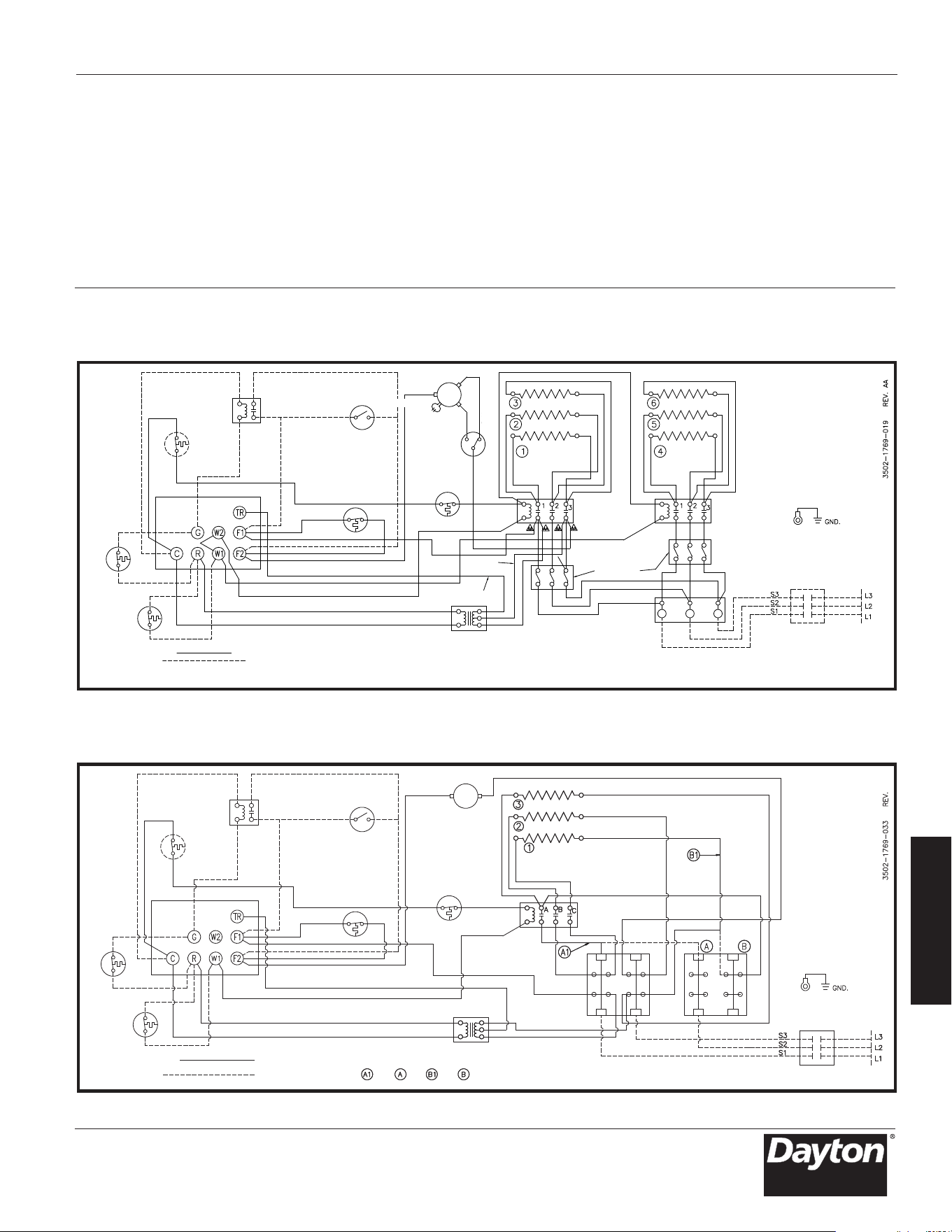
Schémas de câblage (suite)
MOTEUR
ROUGE
Diagram 14: 3 Élément, monophasé et triphasé (modèle 804RZ7)
B
ÉLÉMENT ARRIÈRE
ÉLÉMENTS
CARTE
BORNE DE
CONTRÔLE
RELAIS
VENTILATEUR
TRANSFORMATEUR
RELAIS
VENTILATEUR
T-STAT DE
RÉCUPÉRATION
DE CHALEUR
LIMITE DE
RÉINITIALISATION
MANUELLE
ÉQUIPEMENT OPTIONAL
INSTALLÉ SUR LE TERRAIN
CONNECTÉ EN MONOPHASÉ
CÂBLÉ EN USINE 1 PHASE
POUR RACCORDEMENT TRIPHASÉ
CE BLOC RÉSIDE LE PLUS PRÈS
DES BORNES DE L'ÉLÉMENT
LE CÂBLAGE DU CIRCUI
DE CONTRÔLE DOIT ÊTRE
NEC CLASSE 1 ADAPTÉ
À 600 V
SWITCH POUR 3 PHASE
UNIQUEMENT
INTERRUPTEUR
D'ALIMENTATION
UTILISEZ L1 ET L3 POUR LES
CONNEXIONS MONOPHASÉES
BLOC DE TERMINA D'ALIMENTATION
À UTILISER UNIQUEMENT AVEC DES
CONDUCTEURS EN CUIVRE.
INTERRUPTEUR
DE VENTIL
D'ÉTÉ
LIMITE DE
SURCHAUFFE
TERMOSTAT
POUR POURET
15-Fr
F
R
A
N
Ç
A
I
S
Modèles 804RZ6 à 804RZ9, 804T01 à 804T22
Manuel d’utilisation et de pièces détachées Dayton
Diagramme 13: 6 éléments, 2 contacteurs, triphasés
(modèle 804T06)
RELAIS
VENTILATEUR
LIMITE DE
RÉINITIALI-
SATION
MANUELLE
CARTE
BORNE DE
CONTRÔLE
THERMOSTAT DE
RÉCUPÉRATION DE
CHALEUR
TERMOSTAT
USINE FILAIRE 3 PHASE
ÉQUIPEMENT OPTIONEL
INSTALLÉ SUR LE TERRAIN
INTERRUPTEUR
DE VENTILATEUR
D'ÉTÉ
LIMITE DE
SURCHAUFFE
RELAIS
VENTILATEUR
MARRON
MARRON
MOTEUR
ÉLÉMENTS
CONTACTEUR
BLOC DE FUSIBLE
SI
NÉCESSAIRE
ÉLÉMENTS
SWITCH POUR 3 PHASE UNIQUEMENT
ÉLÉMENT ARRIÈRE
ROUGE
NOIR
NOIR
(240 V UNIQUEMENT)
TRANSFORMATEUR
BLOC DE TERMINAL D'ALIMENTATION
À UTILISER UNIQUEMENT AVEC DES
CONDUCTEURS EN CUIVRE.
INTERRUPTEUR DE
DÉCONNEXION
D'ALIMENTATION
LE CÂBLAGE DU CIRCUIT
DE CONTRÔLE DOIT ÊTRE
NEC CLASSE 1 ADAPTÉ
À 600 V
ROUGE
BLANC
COMMUTATEUR
DE VITESSE
NOIR

Réf. 1 Réf. 3 Réf. 8
Ressort, Réf. 2 Ressort de ret. Réf. 5 Réf. 6 Réf. 7 Tempori-
élément Ressort tube d’élément Réf. 4 Support de Extension Support sateur de
Modèle chauffant capillaire chauffant Interrupteur montage de support d’interrupteur ventilateur
Réf. 17 Réf. 18 Réf. 19
Réf. 10 Réf. 12 Protection Ensemble Protection,
Trans- Réf. 1 Pale de Réf. 13 à limiteur d’éléments élément Réf. 20
Modèle formateur Moteur ventilateur Couvercle linéaire chauffants chauffant Pince
16-Fr
F
R
A
N
Ç
A
I
S
Radiateurs électriques à usage
industriel Dayton
®
Manuel d’utilisation et de pièces détachées Dayton
804RZ6 à 804RZ9, 804T01 à 804T22
804T10 5208-0073-000 5208-0072-000 5208-0074-000 – – – 1215-0256-000 4520-0010-000
804T12 5208-0073-000 5208-0072-000 5208-0074-000 – – – 1215-0256-000 4520-0010-000
804T11 5208-0073-000 5208-0072-000 5208-0074-000 – – – 1215-0256-000 4520-0010-000
804T09 5208-0073-000 5208-0072-000 5208-0074-000 – – – 1215-0256-000 4520-0010-000
804T17 5208-0073-000 5208-0072-000 5208-0074-000 – – – 1215-0256-000 4520-0010-000
804T19 5208-0073-000 5208-0072-000 5208-0074-000 – – – 1215-0256-000 4520-0010-000
804T18 5208-0073-000 5208-0072-000 5208-0074-000 – – – 1215-0256-000 4520-0010-000
804T16 5208-0073-000 5208-0072-000 5208-0074-000 – – – 1215-0256-000 4520-0010-000
804T21 5208-0073-000 5208-0072-000 5208-0074-000 – – – 1215-0256-000 4520-0010-000
804T22 5208-0073-000 5208-0072-000 5208-0074-000 – – – 1215-0256-000 4520-0010-000
804T20 5208-0073-000 5208-0072-000 5208-0074-000 – – – 1215-0256-000 4520-0010-000
804RZ7 5208-0073-000 5208-0072-000 5208-0074-000 – – – 1215-0256-000 4520-0010-000
804RZ8 5208-0073-000 5208-0072-000 5208-0074-000 – – – 1215-0256-000 4520-0010-000
804RZ6 5208-0073-000 5208-0072-000 5208-0074-000 – – – 1215-0256-000 4520-0010-000
804T01 5208-0073-000 5208-0072-000 5208-0074-000 – – 1215-0282-000 1215-0256-000 4520-0010-000
804T02 5208-0073-000 5208-0072-000 5208-0074-000 – – 1215-0282-000 1215-0256-000 4520-0010-000
804RZ9 5208-0073-000 5208-0072-000 5208-0074-000 – – 1215-0282-000 1215-0256-000 4520-0010-000
804T03 5208-0073-000 5208-0072-000 5208-0074-000 – – 1215-0282-000 1215-0256-000 4520-0010-000
804T04 5208-0073-000 5208-0072-000 5208-0074-000 – – 1215-0282-000 1215-0256-000 4520-0010-000
804T05 5208-0073-001 5208-0072-000 5208-0074-000 5216-2053-000 1215-2258-000 – 1215-0256-000 4520-0010-000
804T07 5208-0073-001 5208-0072-000 5208-0074-000 5216-2053-000 1215-2258-000 – 1215-0256-000 4520-0010-000
804T08 5208-0073-001 5208-0072-000 5208-0074-000 5216-2053-000 1215-2258-000 – 1215-0256-000 4520-0010-000
804T06 5208-0073-001 5208-0072-000 5208-0074-000 5216-2053-000 1215-2258-000 – 1215-0256-000 4520-0010-000
804T13 5208-0073-001 5208-0072-000 5208-0074-000 5216-2053-000 1215-2258-000 1215-0282-000 1215-0256-000 4520-0010-000
804T14 5208-0073-001 5208-0072-000 5208-0074-000 5216-2053-000 1215-2258-000 1215-0282-000 1215-0256-000 4520-0010-000
804T15 5208-0073-001 5208-0072-000 5208-0074-000 5216-2053-000 1215-2258-000 1215-0282-000 1215-0256-000 4520-0010-000
804T10 – 3900-2002-006 1210-2000-000 1402-0336-002 4520-0011-000 1802-0087-000 2504-0011-003 –
804T12 5814-0003-002 3900-2005-000 1210-2000-000 1402-0336-002 4520-0011-000 1802-0087-002 2504-0011-003 –
804T11 – 3900-2002-007 1210-2000-000 1402-0336-002 4520-0011-000 1802-0087-001 2504-0011-003 –
804T09 – 3900-2002-006 1210-2000-000 1402-0336-002 4520-0011-000 1802-0087-024 2504-0011-003 –
804T17 – 3900-2002-006 1210-2000-000 1402-0336-002 4520-0011-000 1802-0087-035 2504-0011-003 –
804T19 5814-0003-002 3900-2005-000 1210-2000-000 1402-0336-002 4520-0011-000 1802-0087-005 2504-0011-003 –
804T18 – 3900-2002-007 1210-2000-000 1402-0336-002 4520-0011-000 1802-0087-004 2504-0011-003 –
804T16 – 3900-2002-006 1210-2000-000 1402-0336-002 4520-0011-000 1802-0087-034 2504-0011-003 –
804T21 5814-0003-000 3900-2014-002 1210-0090-000 1402-0339-004 4520-0011-001 1802-0087-006 2504-0013-003 –
804T22 5814-0003-002 3900-0347-005 1210-0090-000 1402-0339-004 4520-0011-001 1802-0087-008 2504-0013-003 –
804T20 5814-0003-000 3900-2014-001 1210-0090-000 1402-0339-004 4520-0011-001 1802-0087-031 2504-0013-003 –
804RZ7 5814-0003-000 3900-2014-002 1210-0090-000 1402-0339-004 4520-0011-001 1802-0087-031 2504-0013-003 –
804RZ8 5814-0003-002 3900-0347-005 1210-0090-000 1402-0339-004 4520-0011-001 1802-0087-011 2504-0013-003 –
804RZ6 5814-0003-000 3900-2014-001 1210-0090-000 1402-0339-004 4520-0011-001 1802-0087-036 2504-0013-003 –
804T01 5814-0003-000 3900-0361-000 1210-0090-001 1402-0339-004 4520-0011-001 1802-0087-012 2504-0012-003 –
804T02 5814-0003-002 3900-0361-001 1210-0090-001 1402-0339-004 4520-0011-001 1802-0087-008 2504-0012-003 –
804RZ9 5814-0003-000 3900-0361-000 1210-0090-001 1402-0339-004 4520-0011-001 1802-0087-037 2504-0012-003 –
804T03 5814-0003-000 3900-0362-000 1210-0096-000 1402-0339-004 4520-0011-001 1802-0087-037 2504-0012-003 482028000
804T04 5814-0003-002 3900-0362-001 1210-0096-000 1402-0339-004 4520-0011-001 1802-0087-011 2504-0012-003 482028000
804T05 5814-0003-000 3900-0364-000 1210-0098-000 1402-0340-004 4520-0011-002 1802-0087-018 2504-0014-003 482028000
804T07 5814-0003-002 3900-2065-000 1210-0098-000 1402-0340-004 4520-0011-002 1802-0087-017 2504-0014-003 482028000
804T08 5814-0003-002 3900-2065-000 1210-0098-000 1402-0340-004 4520-0011-002 1802-0087-019 2504-0014-003 482028000
804T06 5814-0003-000 3900-0364-000 1210-0098-000 1402-0340-004 4520-0011-002 1802-0087-028 2504-0014-003 482028000
804T13 5814-0003-002 3900-0350-001 1210-11004-000 1402-0340-005 4520-0011-002 1802-0087-021 2504-0015-003 482028000
804T14 5814-2021-001 3900-0350-000 1210-11004-000 1402-0340-005 4520-0011-002 1802-0087-022 2504-0015-003 482028000
804T15 5814-0003-002 3900-0350-001 1210-11004-000 1402-0340-005 4520-0011-002 1802-0087-023 2504-0015-003 482028000

Réf. 29 Réf. 30 Réf. 31 Réf. 32 Réf. 33
Réf. 28 Ressort Bornier Bornier de Bornier Boîte à Réf. 34
Modèle Louvre de louvre d’alimentation commande triphasé fusibles Fusible
Réf. 22 Réf. 26 Réf. 27
Réf. 21 Languette Réf. 23 Réf. 24 Réf. 25 Rondelle Vis de mise
Modèle Condensateur de terre Relais Isolateur Douille de terre à la terre
17-Fr
F
R
A
N
Ç
A
I
S
Manuel d’utilisation et de pièces détachées Dayton
Modèles 804RZ6 à 804RZ9, 804T01 à 804T22
804T10 – – - – – 23901-00160 21424-17128
804T12 – – 5018-0004-100 2900-0030-000 – 23901-00160 21424-17128
804T11 – – – 2900-0030-000 – 23901-00160 21424-17128
804T09 – – – – – 23901-00160 21424-17128
804T17 – – – – – 23901-00160 21424-17128
804T19 – – 5018-0004-100 2900-0030-000 – 23901-00160 21424-17128
804T18 – – – 2900-0030-000 – 23901-00160 21424-17128
804T16 – – – – – 23901-00160 21424-17128
804T21 – 3504-7002-001 5018-0005-004 – – – –
804T22 – 3504-7002-001 – 2900-0030-000 – – –
804T20 – 3504-7002-001 5018-0003-000 – – – –
804RZ7 – 3504-7002-001 5018-0005-004 – – – –
804RZ8 – 3504-7002-001 – 2900-0030-000 – – –
804RZ6 – 3504-7002-001 5018-0005-004 – – – –
804T01 – 3504-7002-001 5018-0005-004 – – – –
804T02 – 3504-7002-001 5018-0004-100 2900-0030-000 – – –
804RZ9 – 3504-7002-001 5018-0005-004 – – – –
804T03 1432-0002-003 3504-7002-001 5018-0006-000 – – – –
804T04 1432-0002-003 3504-7002-001 5018-0005-004 2900-0030-000 –- –
804T05 1432-0002-003 3504-7002-001 – – 25221-60131 – –
804T07 1432-11004-000 3504-7002-001 5018-0005-004 2900-0030-000 25221-60131 – –
804T08 1432-11004-000 3504-7002-001 5018-0005-004 2900-0030-000 25221-60131 – –
804T06 1432-0002-001 3504-7002-001 5018-0006-000 – 25221-60131 – –
804T13 1432-0002-004 3504-7002-001 * 2900-0030-000 25221-60131 – –
804T14 1432-0002-004 3504-7002-001 5018-0005-004 – 25221-60131 – –
804T15 1432-0002-004 3504-7002-001 ** 2900-0030-000 25221-60131 – –
804T10 3503-2004-106 5208-7005-001 5823-0004-000 5823-0001-000 – – –
804T12 3503-2004-106 5208-7005-001 5823-0004-000 5823-0002-000 – – –
804T11 3503-2004-106 5208-7005-001 5823-0004-000 5823-0001-000 – – –
804T09 3503-2004-106 5208-7005-001 5823-0004-000 5823-0001-000 – – –
804T17 3503-2004-106 5208-7005-001 5823-0004-000 5823-0001-000 5823-0003-000 – –
804T19 3503-2004-106 5208-7005-001 5823-0004-000 5823-0002-000 – – –
804T18 3503-2004-106 5208-7005-001 5823-0004-000 5823-0001-000 – – –
804T16 3503-2004-106 5208-7005-001 5823-0004-000 5823-0001-000 5823-0003-000 – –
804T21 3503-2004-107 5208-7005-001 5823-11012-000 5823-0002-000 – – –
804T22 3503-2004-107 5208-7005-001 5823-0004-000 5823-0002-000 – – –
804T20 3503-2004-107 5208-7005-001 5823-0004-008 5823-0002-000 5823-0003-000 – –
804RZ7 3503-2004-107 5208-7005-001 5823-11012-000 5823-0002-000 – – –
804RZ8 3503-2004-107 5208-7005-001 5823-0004-000 5823-0002-000 – – –
804RZ6 3503-2004-107 5208-7005-001 5823-11012-000 5823-0002-000 – – –
804T01 3503-2004-107 5208-7005-001 5823-0004-001 5823-0002-000 – – –
804T02 3503-2004-107 5208-7005-001 5823-0004-000 5823-0002-000 – – –
804RZ9 3503-2004-107 5208-7005-001 5823-0004-003 5823-0002-000 5823-0003-000 2025-0002-000 2019-0007-010
804T03 3503-2004-107 5208-7005-001 5823-0004-002 5823-0002-000 – – –
804T04 3503-2004-107 5208-7005-001 5823-0004-002 5823-0002-000 – – –
804T05 3503-2004-108 5208-7005-001 5823-0004-003 5823-0002-000 – 480030004 2019-7008-079
804T07 3503-2004-108 5208-7005-001 5823-0004-002 5823-0002-000 – – –
804T08 3503-2004-108 5208-7005-001 5823-0004-001 5823-0002-000 – – –
804T06 3503-2004-108 5208-7005-001 5823-0005-000 5823-0002-000 – 480030004 2019-7008-080
804T13 3503-2004-108 5208-7005-001 5823-0004-002 5823-0002-000 – – –
804T14 3503-2004-108 5208-7005-001 5823-0005-000 5823-0002-000 – 480030004 2019-7008-079
804T15 3503-2004-108 5208-7005-001 5823-0004-002 5823-0002-000 – *** ****
* Deux relais sont utilisés, le relais 40A 5018-0005-004 et le relais 35A 5018-0004-100
** Deux relais sont utilisés, le relais 50A 5018-0006-000 et le relais 35A 5018-0004-100
*** Deux blocs de fusibles sont utilisés, (30 A) bloc 600 V 2025-0001-000 et 2025-7004-000
**** Deux styles de fusibles sont utilisés, (30A) 600V 2019-7002-008 et (50A) 600V 2019-7002-012

Symptôme Cause(s) possible(s) Action corrective
Le thermostat envoie un
appel de chaleur mais le
radiateur ne fonctionne pas
Le moteur du ventilateur
chauffe
Le moteur du ventilateur
fonctionne, mais ne
propage pas d’air chaud
1. Fusible ouvert (grillé)
2. Câblage incorrect
3. Protection thermique non réarmable
ouverte, mettre hors tension les
éléments chauffants et contrôler
les circuits
1. Accumulation de poussière ou saleté
excessive sur le moteur du ventilateur
2. Accumulation de saleté
3. Le moteur a besoin d’être lubrifié
1. Le contact des éléments chauffants
ne fonctionne pas correctement
2. Un fusible d’élément est grillé
1. Remplacer les fusibles, rechercher la cause
(voir la liste des pièces de rechange pour
la dimension du fusible)
2. Vérifier les raccordements des fils
3. Vérifier ce qui suit :
Alimentation correcte en tension et phase.
Câblage de commande correct (la commande
du radiateur doit passer par la section câblée
de commande du thermostat seulement).
Interruption de l’alimentation du radiateur
pendant son fonctionnement. Obstruction
de la circulation d’air autour du radiateur :
purger pendant 1 à 5 minutes en ayant
le thermostat désactivé
1. Nettoyer le moteur du ventilateur et le carter
pour enlever toute accumulation de graisse
ou d’huile.
2. Nettoyer les louvres et entre les éléments
chauffants
3. Voir la section Entretien
1. Vérifier la continuité du câblage. Remplacer
le contacteur s’il est défectueux
2. Remplacer les fusible, rechercher la cause
18-Fr
F
R
A
N
Ç
A
I
S
Radiateurs électriques à usage
industriel Dayton
®
804RZ6 à 804RZ9, 804T01 à 804T22
Manuel d’utilisation et de pièces détachées Dayton

GARANTIE LIMITÉE
GARANTIE LIMITÉE D’UN AN FOURNIE PAR DAYTON. LES MODÈLES DE RADIATEURS ÉLECTRIQUESÀUSAGE INDUSTRIEL
DAYTON
®
COUVERTS DANS CE MANUEL SONT GARANTIS PAR DAYTON ELECTRIC MFG.CO. AU PREMIER UTILISATEUR
CONTRE TOUT DÉFAUT DE FABRICATION OU DE MATÉRIAU DANS DES CONDITIONS D’UTILISATION NORMALES DURANT
UN ANÀCOMPTER DE LA DATE D’ACHAT. TOUTE PIÈCE PRÉSENTANT, SELON DAYTON, DES DÉFAUTS DE FABRICATION
OU DE MATÉRIAU ET RETOURNÉE À UN CENTRE DE SERVICE AGRÉÉ
DÉSIGNÉ PAR DAYTON, PORT PAYÉ, SERA RÉPARÉE
OU REMPLACÉE AU CHOIX DE DAYTON, À TITRE DE RECOURS EXCLUSIF. VOIR LES PROCÉDURES DE RÉCLAMATIONS SOUS
GARANTIE SOUS LA RUBRIQUE « PROMPT RÈGLEMENT », CI-APRÈS. LA PRÉSENTE GARANTIE DONNE AUX ACHETEURS DES
DROITS SPÉCIFIQUES QUI VARIENT SELON LES JURIDICTIONS.
LIMITES DE RESPONSABILITÉ. DANS LA MESURE PERMISE AU TITRE DE LA LOI APPLICABLE, DAYTON DÉCLINE
EXPRESSÉMENT TOUTE RESPONSABILITÉ POUR TOUT DOMMAGE ACCESSOIRE ET IND
IRECT. LA RESPONSABILITÉ DE
DAYTON EST DANS TOUS LES CAS LIMITÉE ET NE SAURAIT DÉPASSER LE PRIX D’ACHAT.
CLAUSE D’EXONÉRATION DE GARANTIE. DAYTON S’EST DILIGEMMENT EFFORCÉE D’ILLUSTRER ET DE DÉCRIRE DE
MANIÈRE EXACTE LES PRODUITS DE CETTE BROCHURE. CEPENDANT, CES ILLUSTRATIONS ET CES DESCRIPTIONS NE SONT
DONNÉES QU’À TITRE D’IDENTIFICATION ET NE GARANTISSENT PAS EXPRESSÉMENT OU IMPLICITEMENT QUE LES PRODUITS
SONT DE QUALITÉ MARCHANDE OU ADAPTÉS À UN USAGE PARTICULI
ER, OU QU’ILS SERONT NÉCESSAIREMENT CONFORMES
AUX ILLUSTRATIONS OU AUX DESCRIPTIONS FOURNIES. SAUF DISPOSITIONS CONTRAIRES CI-DESSOUS, AUCUNE GARANTIE
OU AFFIRMATION DE FAIT, EXPRESSE OU IMPLICITE, AUTRE QUE CELLE ÉNONCÉE À LA RUBRIQUE«GARANTIE LIMITÉE »
CI-DESSUS, N’EST FOURNIE OU AUTORISÉE PAR DAYTON.
Conseils et recommandations techniques; clause d’exonération. Nonobstant toute pratique ou action commerciale
ayant eu cours dans le passé ou toute coutume d
u secteur d’activité, les ventes n’incluront pas la fourniture de conseils
en matière de conception de système ou de résolution de problèmes techniques. Dayton n’assume aucune obligation ni
responsabilité en ce qui concerne les recommandations, opinions ou conseils non autorisés relatifs au choix, à l’installation
ouàl’utilisation des produits.
Adéquation du produit. Dans de nombreuses juridictions, les codes et les réglementations qui régissent les ventes, la
construction, l’installation et/ou l’utilisation de produits pour certains usages peuvent être différents de ceux de régions
avoisinantes. Bien que Dayton se soit efforcée de rendre ses produits conformesàces codes, la société ne peut en garantir
l
a conformité et ne saurait être responsable de la manière dont les produits sont installés ou utilisés. Avant d’acheter et
d’utiliser un produit, il est conseillé d’étudier son application ainsi que les codes et réglement
ations nationaux et locaux,
et de s’assurer de la conformité à ces codes de ces produits, de leur installation et de leur utilisation.
Certains aspects des dénis de garantie ne sont pas applicables aux produits de consommation. par exemple (a) certaines
juridictions n’autorisent pas l’exclusion ou la limitation des dommages accessoires ou indirects, de sorte que la limitation
ou l’exclusion susmentionnée peut ne pas s’appliquer à votre cas; (b) en outre, certaines jur
idictions n’autorisent pas de
limite sur la durée d’une garantie implicite, par conséquent la limite susmentionnée peut ne pas s’appliquer à votre cas;
et (c) en vertu de la loi, durant la période de garantie limitée, toute garantie implicite de qualité marchande ou d’adéquation
à un usage particulier applicable aux produits de consommation achetés par des consommateurs, est susceptible de ne pas
pouvoir être exclue ou autrement déniée.
Prompt règlement. Dayton s’eff
orcera en toute bonne foi de faire les rectifications ou autres ajustements prévus pour tout
produit qui s’avère défectueux durant la période de garantie limitée. Pour tout produit jugé défectueux durant la période
de garantie limitée, contacter tout d’abord le concessionnaire où l’appareil a été acheté. Le concessionnaire fournira des
instructions supplémentaires. S’il est impossible de résoudre le problème de façon satisfaisante, écrire à Dayton à l’adresse
ci-
dessous, en indiquant le nom et l’adresse du concessionnaire, la date et le numéro de la facture du concessionnaire,
ainsi que la nature du défaut constaté. Le titre et le risque de perte passentàl’acheteur au moment de la livraison par le
transporteur. Si le produit a été endommagé pendant le transport, une réclamation doit être faite auprès du transporteur.
Fabriqué pour Dayton Electric Mfg. Co., 100 Grainger Parkway, Lake Forest, Illinois 60045-5201 États-Unis
Fabriqué pour Dayton Electric Mfg. Co.
Lake Forest, Illinois 60045 États-Unis
19-Fr
F
R
A
N
Ç
A
I
S
Modèles 804RZ6 à 804RZ9, 804T01 à 804T22
Manuel d’utilisation et de pièces détachées Dayton
804RZ6 à 804RZ9, 804T01 à 804T22

20-Fr
F
R
A
N
Ç
A
I
S
Remarques
804RZ6 à 804RZ9, 804T01 à 804T22
Manuel d’utilisation et de pièces détachées Dayton
