1
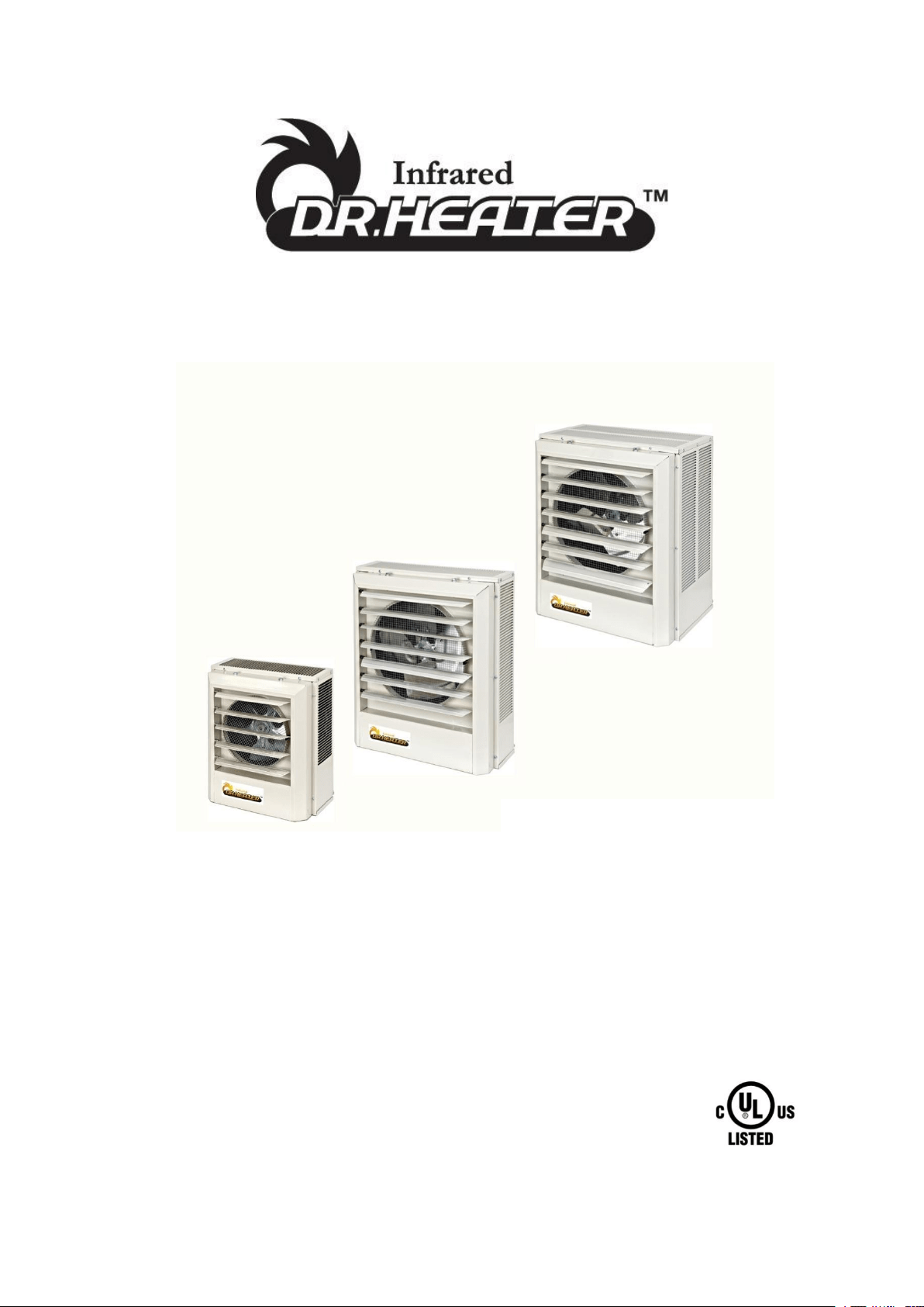
Heavy-Duty Electric Unit Heaters
OWNER’S MANUAL
IMPORTANT INSTRUCTIONS
READ & SAVE
Model: DR-P130
DR-P350
DR-P275
DR-P2100
DR-P3150
DR-P3200

2
IMPORTANT INSTRUCTIONS
PLEASE READ ALL INSTRUCTIONS BEFORE USING THIS HEATER
NOTE: There may be a trace of smoke or odor when unit is first operated. Don’t be alarmed.
This indicates that a drop of oil fell on the heating coil during the manufacturing process. It
will quickly evaporate and should not re-occur.
Make sure that the room in which the appliance is located is well ventilated during this
operation. It is normal for the appliance to emit small cracking sounds when you turn it on for
the first time. Do not be alarmed.
WHEN USING ELECTRICAL APPLIANCES, BASIC PRECAUTIONS SHOULD ALWAYS BE
FOLLOWED TO REDUCE RISK OF FIRE, ELECTRICAL SHOCK AND INJURY TO PERSONS,
INCLUDING THE FOLLOWING:
1) Read all instructions before using this heater.
2) This heater is hot when in use. To avoid burns, do not let bare skin touch hot surfaces. Keep
combustible materials, such as furniture, pillows, bedding, papers, clothes, and curtains at least 3’
(0.9 m) from the front of the heater and keep them away from the sides and rear.
3) Extreme caution is necessary when any heater is used by or near children or invalids and
whenever the heater is left operating and unattended.
4) Always switch off the heater when not in use.
5) Do not operate any heater after the heater malfunctions, has been dropped or damaged in any
manner. Disconnect power at service panel and have heater inspected by a reputable electrician
before reusing.
6) Do not use outdoors.
7) To disconnect heater, turn off power to heater circuit at main disconnect panel.
8) Do not install less than 6 feet high from the floor.
9) Do not insert or allow foreign objects to enter any ventilation or exhaust opening as this may
cause an electric shock or fire, or damage the heater.
10) To prevent a possible fire, do not block air intakes or exhaust in any manner.
11) A heater has hot and arcing or sparking parts inside. To reduce the risk of fire, do not use it in
areas where gasoline, paint, or flammable vapors and liquids are used or stored.
12) Use this heater only as described in this manual. Any other use not recommended by the
manufacturer may cause fire, electric shock, or injury to persons.
13) This product must be installed by a certified electrician, in accordance with local codes.
14) WARNING – RISK OF FIRE, DO NOT USE AS A RESIDENTIAL OR HOUSEHOLD HEATER.
15) Do not install closer than 1 foot (0.3 m) from both sides and rear of heater to any adjacent
surface/wall.
CAUTION – High temperature, risk of fire, keep electrical cords, drapery, furnishings, and
other combustibles at least 3 feet(0.9 m) from the front of the heater and away from the side
and rear.
SAVE THESE INSTRUCTIONS
WARNING – RISK OF FIRE, DO NOT USE AS A RESIDENTIAL OR HOUSEHOLD HEATER.
3
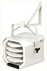
Features and Benefits
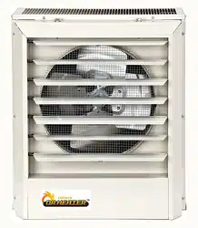
These heavy-duty Electric forced-air unit heaters are suited for factories, schools, service
buildings, dormitories, hospitals, stock rooms and other public buildings. The Heaters’ high
capacity and wide range of voltages/phases selections meet most installation requirements. All
units are equipped with overheat protection and a totally enclosed, permanently lubricated motor.
Can be installed for use in down flow or horizontal applications.
Heavy-duty bearing, permanently lubricated, totally enclosed overheat protected Motor
Heavy-duty finned steel sheath heating element for lower operation and longer life
Heavy-gauge die-formed steel housing for maximum impact resistance
High efficient, dynamically balanced fan blade
208-480V 1/3 phases 3-20 KW
Optional vertical and horizontal brackets available
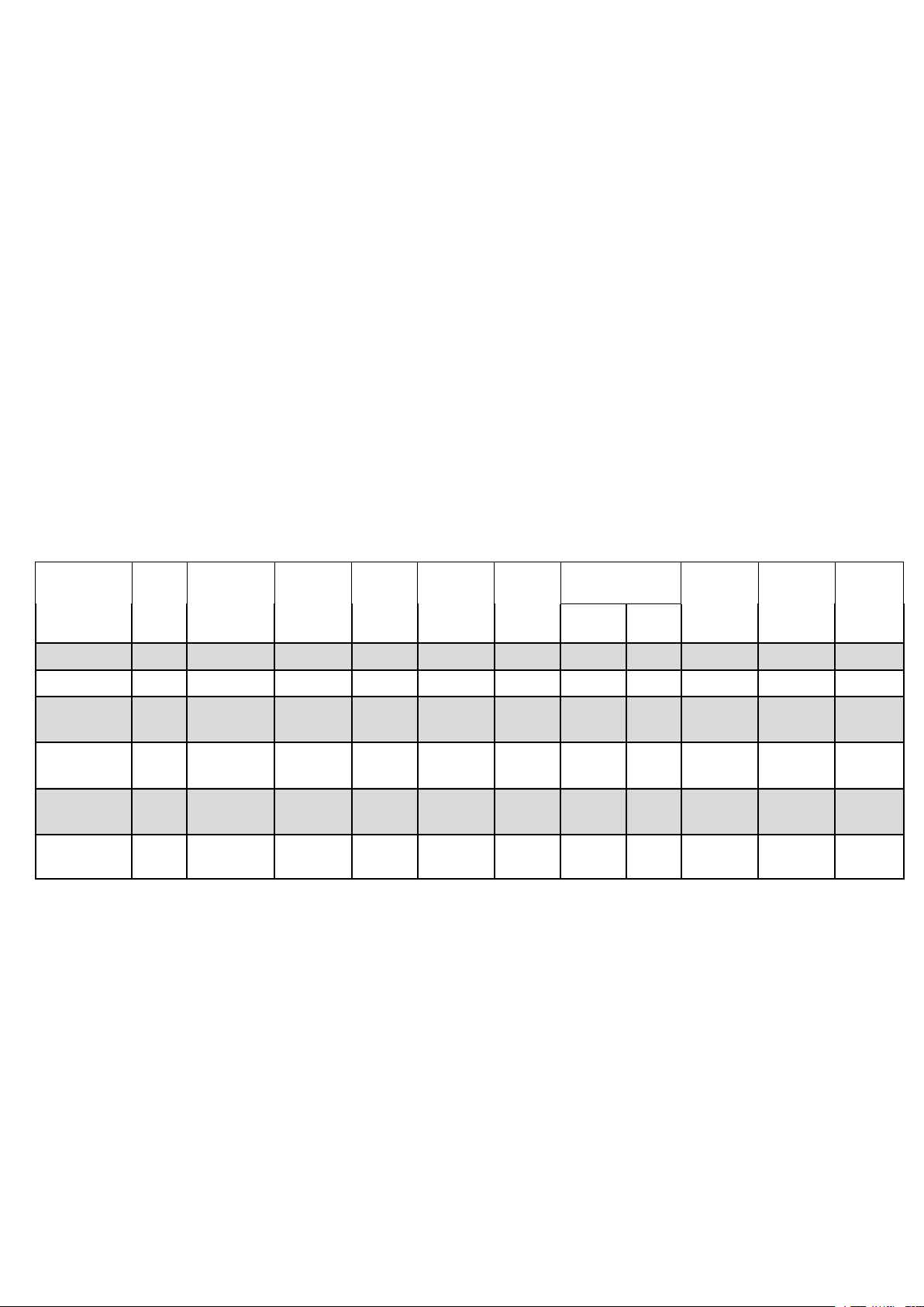
Specifications
Model
KW
BTU/HR
1000’S
Heater/
Motor
Voltage
Phase
Control
Voltage
Amps
Per
Phase
Fan Motor
CFM at
Outlet
FPM at
Outlet
Air
Temp
Rise
(℉)
HP
RPM
DR-P130
3
10.2
208
1
208
14.5
1/100
1600
350
800
27
DR-P350
5
17
480
3
24
6
1/100
1600
350
800
45
DR-P275
7.5
25.6
208
1 or 3
24
36
1/30
1600
650
970
37
DR-P2100
10.0/
7.5
34.1/25.6
240/208
1 or 3
24
42.0/
36.0
1/30
1600
650
970
49
DR-P3150
15.0/
11.2
51.2/38.2
240/208
3
24
36.1/
33.3
1/20
1530
910
1640
52
DR-P3200
20
68.2
480
3
24
24
1/10
1500
1320
2060
48
4
All wiring must be installed by a certified electrician according to the electrical safety.
The ceiling heater must be grounded in accordance with all national and local building codes.
All wiring procedures and connections shall be in accordance with the national and local
codes having jurisdiction.
Before installation:
Disconnect the main supply connection.
The heater must be connected to individual branch circuit.
CAUTION: High temperature, risk of fire, keep electrical cords, drapery, furnishings, and other
combustibles at least 3 feet (0.9 m) from the front of the heater and away from the side and rear.
WARNING: To reduce the risk of fire, do not store or use gasoline or other flammable vapors and
liquids in the vicinity of the heater.
CAUTION : Mount the heater at least 6 feet above the floor to prevent accidental contact with
the fan blade which could cause injury.
CAUTION: To prevent possible over heating or damage due to overheating, keep at least a 5 feet
clearance in front of the heater. Refer to Table 1 for side, top and back clearance requirements.
Installation location:
1 Arrange units so their discharge air streams are subjected to a minimum of interference from
columns and partitions.
2 Direct air stream away from room occupants in comfort heating.
3 Air streams should wipe exposed wall without blowing directly at them.
4 Direct air stream along the windward side of a room when installed in a building exposed to a
prevailing wind.
5 If using a remote thermostat, locate thermostat approximately 5 feet above partition walls or posts
away from cold drafts, internal heat sources, and away from heater discharge air streams.
6 Large rooms require multi-unit installations. Arrange units to provide perimeter air circulation
where each unit supports the air stream from another.
Table 1 - Wall and Ceiling Clearance, inches(mm) / Mounting Brackets
Unit
Discharge
Ceiling
Side Wall
Back Wall
3 & 5 kW
Horiz.
2” (50.8)
6” (152.4)
9” (228.6)
Vert.
6” (152.4)
18” (457.2)
18” (457.2)
7.5 to 10 kW
Horiz.
6” (152.4)
6” (152.4)
13” (330.2)
Vert.
6” (152.4)
24” (609.6)
24” (609.6)
15 to 20 kW
Horiz.
6” (152.4)
9” (228.6)
12
1
/2” (317.5)
Vert
6” (152.4)
24” (609.6)
24” (609.6)
INSTALLING INSTRUCTIONS
5
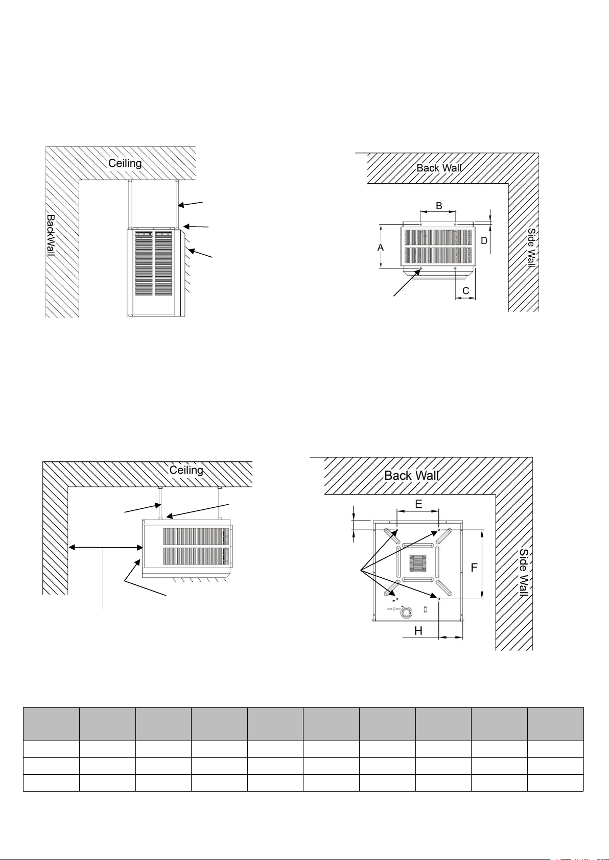
MOUNTING
ROD MOUNTING
HORIZONTAL DISCHARGE
1 Install four threaded mounting rods in the threaded holes and secure in place using lock nuts.
2 Securely attach the four mounting rods to the ceiling. (Refer to Table 1 for wall and ceiling
clearances, and Table 2 for mounting rod spacing)
VERTICAL DISCHARGE
1 Remove bolts from the threaded holes in the back of the heaters.
2 Install four threaded mounting rods in the threaded holes and secure in place using lock nuts.
3 Securely attach the four mounting rods to the ceiling. (Refer to Table 1 for wall and ceiling
clearances, and Table 2 for mounting rod spacing dimensions.)
Table 2 - Mounting Rod Spacing
Model
Thread
type
A
B
C
D
E
F
G
H
3-5 kW
5/16-18
6 1/16”
6”
4 1/16”
3/4”
6”
9 3/4”
2”
4 3/16”
7.5-10 kW
5/16-18
6 1/16”
8 7/8”
5 1/8”
3/4”
8 7/8”
14 5/8”
2”
5 1/8”
15-20 kW
5/16-18
11 3/8”
8 7/8”
5 1/8”
3/4”
8 7/8”
14 5/8”
2”
5 1/8”
Mounting
Rod(4)
Lock Nut
Unit Heater
6 Feet Min. Clearance to Floor
Threaded
Mounting
Holes(4)
Mounting
Rod(4)
Lock Nut
Clearance Equal to Depth of Heater
to Permit Full Opening of The Access
Door
Access Door
Threaded
Mounting
Holes(4)
6
WIRING
BRANCH CIRCUIT (POWER)
1. Connect heater only to the voltage, amperage and frequency specified on the nameplate.
2 Field wiring must be properly sized to carry the amperage in accordance with the NEC.
3 The access door is hinged. There are either one or two screws accessible from the bottom that
must be removed to gain access.
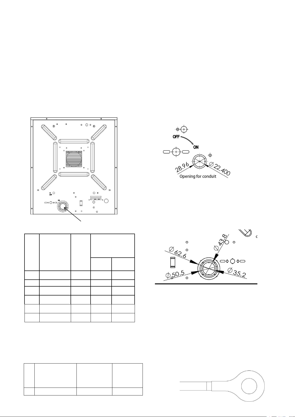
4 A knockout is provided in the back of the heater close to the power terminal board. The control
terminal board knockout is 1/2 inch conduit size. The power terminal block knockout is multiple
diameter. Use the diameter that fits the required conduit size.
5 A ground terminal is provided near the power terminal board. The ground wire should be
connected before other connections are made. Use grounding lug to install the grounding wire.
The ground wire AWG# and the lug screw size is as below list:
No.
Model #
Trade
size of
conduit
(inch)
Knockout(mm)
Nominal
Minimum
1
DR-130
1/2
28.96
22.4
2
DR-350
1/2
28.96
22.4
3
DR-P275
1
43.8
35.2
4
DR-P2100
1
43.8
35.2
5
DR-P3150
1
43.8
35.2
6
DR-P3200
1/2
28.96
22.4
No.
Model#
Grounding
wire
AWG#
Grounding
Lug Screw
Size
1
DR-P130
14
M5X1.0
knockout here
For model DR-P130 and DR-P350
For model DR-P2100, DR-P275,
DR-P3150 and DR-P3200
7
6 The power terminal board is equipped with box terminals sized to accept the correct size power
supply wire. Wire rated at 600V and 60°C is satisfactory for the heater branch circuit. Copper wire
is satisfactory for connection to the heater power terminal board box terminal.
7 Each heater has a wiring diagram affixed to the inside of the access door. Consult this diagram
before making any field connections.
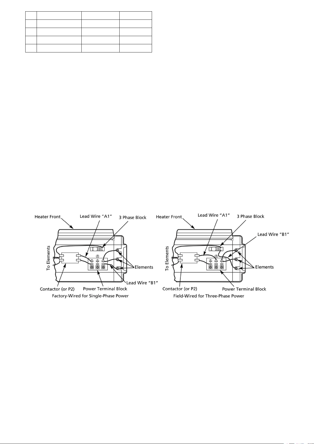
8 Single or three-phase connections may be used with heater models DR-P275 and DR-P2100.
These units are factory wired for single phase operation. If these heaters are for use with three-
phase power, reconnect the wires as indicated in the wiring diagram attached to the heater.
9 For model DR-P275 and DR-P2100 (Figure 4a), move only the two wires marked “A1" and
marked
“
B1
”,
do not move or change any other wiring. The element lead wire marked“B1” which is
factory connected to the power terminal block (terminal located closest to the elements) must be
moved to terminal “B” on the three-phase terminal block.
10 The relay (contactor lead wire“A1") must be moved from the end terminal of the power terminal
block (terminal closest to the contactor or control terminal board) to the "A
”
terminal of the lower
terminal block (center terminal).
11 Electrical Accessories, either kits or factory-installed options, are shown connected by a dashed
line on the heater wiring diagram.
Note: We do not include the thermostat, we use a jumper wire to connect the thermostat terminals,
if you want to use a thermostat, you must remove the jumper wire, or not the thermostat cannot
work.
12 208/240 VOLT HEATER. The heaters are wired for 240V from factory. When heater is to be
connected to 208V supply, the transformer leads have to be inter changed. Inter change
transformer red and black primary leads (see wiring diagram on heater door). The white color
lead is the COMMON for the 40VA control transformer provided with these heaters.
2
DR-P350
14
M5X1.0
3
DR-P275
6
M6X1.0
4
DR-P2100
6
M6X1.0
5
DR-P3150
6
M6X1.0
6
DR-P3200
10
M6X1.0
Figure 4a - Wiring Connections for Single-Phase and Three-Phase
Power (DR-P275 and DR-P2100)

8
CONTROL WIRING
Line voltages is present on some of the terminals on the control terminal board. Always
disconnect the power from the heater before making any connections to the control board to
prevent hazard.
1.Use min. 600 volt, NEC Class 1 insulated wire for all control circuit wiring.
2.Use a crimp-on type fork terminal on the wire ends that attach to the control terminal board if more
than one connection is to be made under the terminal screw.
3.Control wiring must be rated minimum 18 AWG.
NOTE: Thermostat and control circuit wiring must be suitable to handle the full load of the heater
(example DR-P2100 is rated 42 amps).
Operation Instructions
1 Heater must be properly installed before operation.
2 Turn power supply to heater “ON” at main service panel.
3 Where applicable, refer to control accessory instructions regarding proper operation of any
controls or accessories used with the heater.
It is important to keep this heater clean. Your heater will give you years of service and comfort with
only minimum care. To assure efficient operation follow the simple instructions below.
MAINTENANCE CLEANING INSTRUCTIONS
(To be performed only by Qualified Service Personnel)
At least annually, the heater should be cleaned and serviced by a qualified service person to assure
safe and efficient operation. This should include the removal of the grille and, as necessary the
heater from the back box to clean residue from the unit. After completing the cleaning and servicing,
the heater should be fully reassembled and checked for proper operation.
To reduce the risk of fire and electric shock or injury, disconnect all power coming to heater at main
service panel and check that the element is cool before servicing or performing maintenance.
USER CLEANING INSTRUCTIONS
1.After the heater has cooled, a vacuum cleaner with brush attachment may be used to remove dust
and lint from exterior surfaces of the heater including the grille openings.
2.With a damp doth, wipe dust and lint from grille and exterior surfaces.
3.Return power to heater and check to make sure it is operating properly.
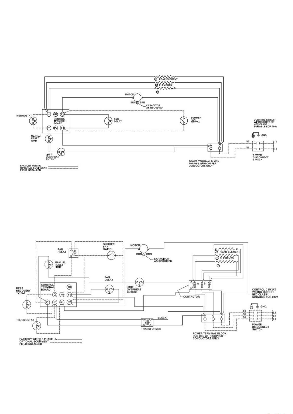
9
Wiring Diagrams
DR-P130
DR-P350
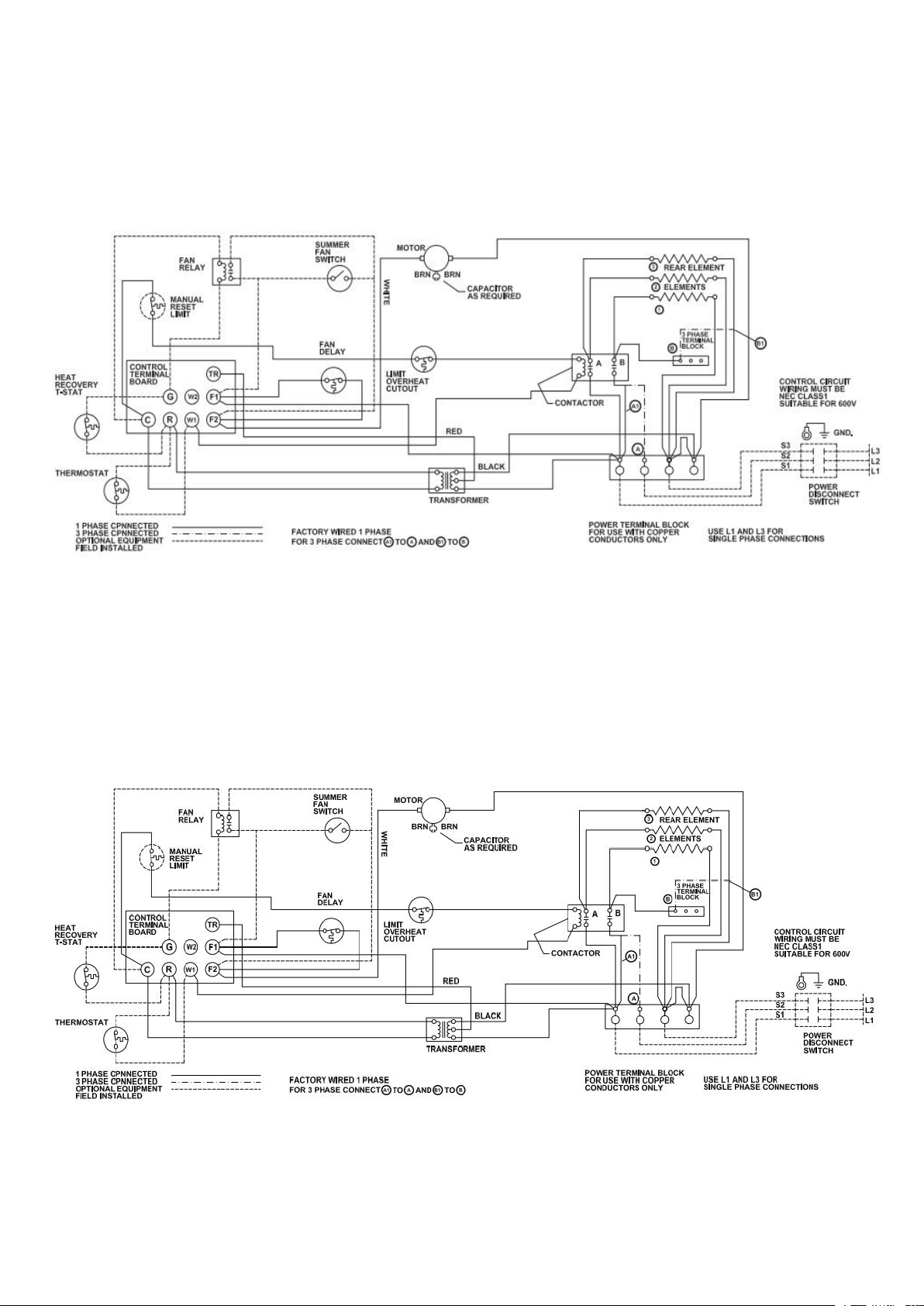
10
DR-P2100
DR-P275
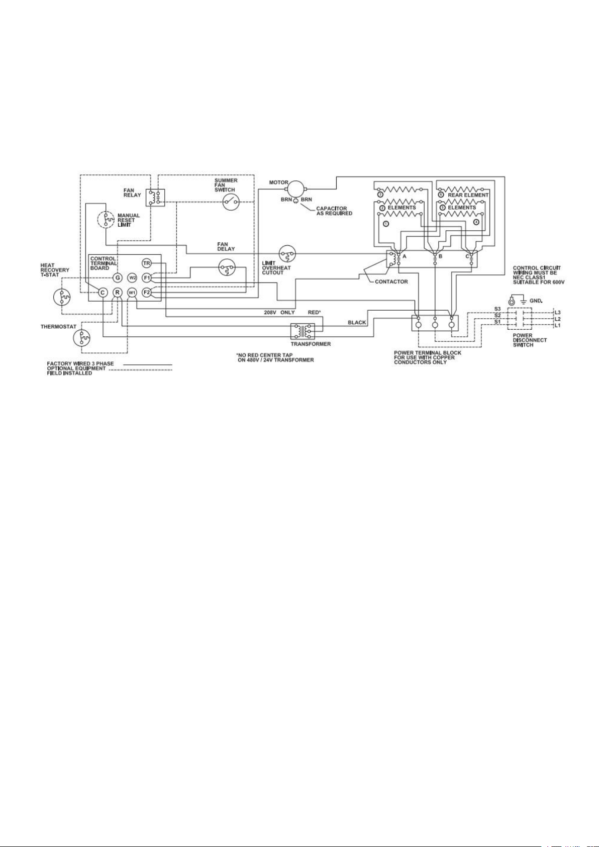
11
DR-P3150&DR-P3200

12
If your heater fails to operate, please follow these procedures:
This heater has a thermal cut-off protection. If the thermal cut-off protection trips, switch off the
power, switch off the circuit breaker. The unit should reset automatically after 10-30 minutes. If
the thermal cut-off protection trips again, consult a certified/licensed electrician to determine the
reason for overheating.
Problem
Probable Cause
Solution
Unit is not heating.
Overheat protection has temporarily
deactivated the heater.
Turn the heater OFF. Switch off the circuit
breaker. Wait 10-30 minutes before turning on
the heater.
Breaker/Fuse has been tripped.
Check your electrical box to confirm the
breaker has not been blown. This may occur if
the receptacle is shared with other high
consumption appliances.
The heater is
producing a burning
smell.
Check & ensure there are no combustible
materials within 0.9 meters (3 feet) surrounding
the heater.
Remove any combustible items from the vicinity
of the heater.
A drop of oil fell on the heating coil during the
manufacturing process. It will quickly evaporate
and should not occur again.
Ensure room in which heater is situated is well
ventilated.
Ensure a minimum clearance of 1 foot (0.3 m)
from both sides and rear of heater to any
adjacent surface/wall.
Reposition the heater so there is enough space
between the heater and any adjacent
surface/wall.
PLEASE DO NOT ATTEMPT TO OPEN OR REPAIR THE HEATER YOURSELF. DOING SO COULD
CAUSE DAMAGE TO THE HEATER OR PERSONAL INJURY.
TROUBLE SHOOTING
13
How long is the warranty?
This heater comes with a ONE-YEAR LIMITED COMPONENT WARRANTY. If your unit does not appear to be working
properly, please contact our service center by calling 1-800-317-1688. Prior to your call, we encourage you to visit our
service related website www.DrHeaterUSA.com for troubleshooting tips and service instructions if needed.
Warranty Information
Register your product at our website:
Or visit DrHeaterUSA.com/register-your-heater
Feedback
Love it? Help us make the product more for you.
Let us know with a customer review.
Please visit:
https://www.amazon.com/review/review-your-purchases#
At Dr. Heater USA, we are committed to bringing top quality alternative & supplemental heating products to our customers
.
Dr. Heater USA
860 Mahler Road
Burlingame, CA 94010
Tel: 1-800-317-1688
EMAIL: [email protected]
Dr Heater USA
@DrHeaterUSA
Dr. Heater USA
Dr. Heater USA