Operator’s Manual
www.mechmaxx.com
WARRANTY


TABLE OF CONTENTS
TABLE OF CONTENTS
SPECIFICATIONS
SAFETY SIGNS
IMPORTANT SAFETY INFORMATION
1
2
BLADE AND BREAKER MAINTENANCE
20
ROTOR BLADES MAINTENANCE
20
ADJUSTING BELT TENSION
22
BOLT TORQUE
22
ENGLISH TORQUE SPECIFICATIONS
22
YOUR SAFETY
EQUIPMENT SAFETY GUIDELINES
4
4
LOWER HITCH ARM
9
CONNECTING ROD
10
UPPER HINGE PLATES
11
INFEED CHUTE
12
DISCHARGE CHUTE
13
CONTROL ARM LINKAGE
15
OPERATION
SEPARATE PTO HALVES
17
17
CHIPPING OPERATION
18
UNPLUGGING
18
SEVERE PLUG
18
HYDRAULIC OIL
19
START UP
19
STOPPING
19
INFEED ROLLER CONTROL
19
DISCHARGE CHUTE
20
3
4
6
9
CONTENTS SUPPLIED
ASSEMBLY
17
OPERATION
20
MAINTENANCE
23
PARTS DIAGRAM
24
PARTS LIST
1
www.mechmaxx.com
TABLE OF CONTENTS

SPECIFICATIONS
2
www.mechmaxx.com
SPECIFICATIONS
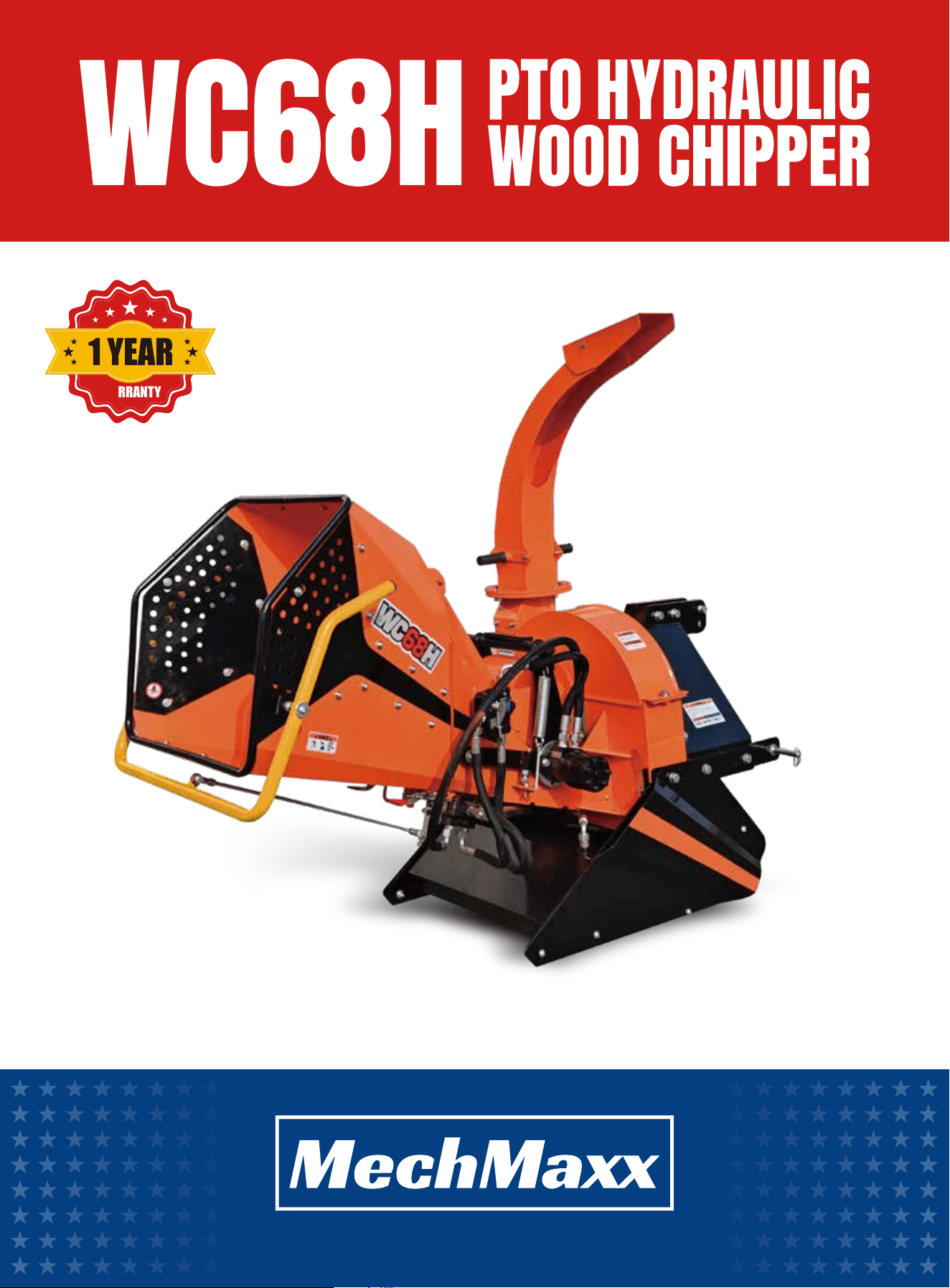
Model WC68H
Tractor Power
Max. Throughput Capacity
Infeed Opening
lnfeed Chute Opening
Discharge Chute Rotation
Flywheel Diameter
Flywheel Thickness
Flywheel Speed
Flywheel Drive System
Flywheel Shaft Diameter
Flywheel Housing Thickness
Number Of Blades
3-Point Hitch
Hydraulic System
Hydraulic Pump
Hydraulic Oil Capacity
Infeed Roller Size
Infeed Roller Pressure
Infeed Roller Speed
Feed Control
N.W./G.W.
Packaging Dimensions
Overall Dimensions
20 - 50 HP
6 in
6 × 8 in
27.5 × 25 in
360 Degrees
23.6 in
0.75 in
540–1000 RPM
Direct drive
2 in
5/16 in
4 reversible double-edged blades
CAT 1
Standard RP/R fittings and valves
Belt-driven
5.3 gal
7.3 in
Adjustable via spring tension
34–62.5 RPM
Forward / Neutral / Reverse
746 / 840 LBS
45 × 33 × 45 in
76 × 35.6 × (67–68.7) in

3
www.mechmaxx.com
SAFETY SIGNS
SAFETY SIGNS
The rating plate on your machine may show symbols. These represent important information about the product or instruc-
tions on its use.

4
www.mechmaxx.com
IMPORTANT SAFETY INFORMATION
IMPORTANT SAFETY INFORMATION
YOU are responsible for the SAFE operation and mainte-
nance of your Tractor Wood Chipper. YOU must ensure
that you and anyone else who is going to operate, main-
tain, or work around the Tractor Wood Chipper are familiar
with the operation and maintenance procedures and relat-
ed SAFETY information contained in this manual.
This manual will take you step by step through your work-
ing day and alert you to all good safety practices that
should be followed while operating the Tractor Wood
Chipper.
Remember, YOU are the key to safety. Good safety
practices not only protect you but also the people around
you. Make these practices a working part of your safety
program. Be certain that EVERYONE operating this equip-
ment is familiar with the recommended operating and
maintenance procedures and follows all the safety
precautions. Most accidents can be prevented. Do not
risk injury or death by ignoring good safety practices.
1. Tractor Wood Chipper owners must provide operating
instructions to operators or employees before allowing
them to operate the machine, and at least annually there-
after.
2. The most important safety device on this equipment is
a SAFE operator. It is the operator’s responsibility to read
and understand ALL Safety and Operating instructions in
this manual and to follow them. Most accidents can be
avoided.
3. A person who has not read and understood all operating
and safety instructions is not qualified to use the
machine. An untrained operator exposes himself and
bystanders to possible serious injury or death.
4. Do not modify the equipment in any way. Unauthorized
modifications may impair the function and/or safety and
could reduce the service life of the equipment.
5. Think SAFETY! Work SAFELY!
1. Read and understand the Operator’s Manual and all
safety signs before operating, maintaining, adjusting, or
cleaning the Tractor Wood Chipper.
2. Keep a first-aid kit available and ensure you know how
to use it.
3. Keep a fire extinguisher available and ensure you know
how to use it.
4. Do not allow riders.
5. Wear appropriate protective gear. This includes, but is
not limited to:
- A hard hat
- Protective shoes with slip-resistant soles
- Heavy gloves
- Wet weather gear
- Hearing protection
6. Install and secure all guards before starting the
machine.
7. Wear suitable ear protection during prolonged exposure
to excessive noise.
8. Clear the work area of people, especially children,
before operating the unit.
9. Review all safety-related items at least annually with
anyone who will be operating or maintaining the Tractor
Wood Chipper.
1. Safety of the operator and bystanders is one of the
main concerns in designing and developing equipment.
However, every year many accidents occur which could
have been avoided by a few seconds of thought and a
more careful approach to handling equipment. You, the
operator, can avoid many accidents by observing the
following precautions in this section. To avoid personal
injury or death, study the following precautions and insist
those working with you, or for you to follow them.
2. In order to provide a better view, certain photographs or
illustrations in this manual may show an assembly with a
safety shield removed. However, equipment should never
be used in this condition. Keep all shields in place. If
shield removal becomes necessary for repairs, replace
the shield prior to use.
YOUR SAFETY
EQUIPMENT SAFETY GUIDELINES
GENERAL SAFETY

5
www.mechmaxx.com
Many features incorporated into this machine are the
result of suggestions made by customers like you. Read
this manual carefully to learn how to use the chipper
safely and how to set it to provide maximum field efficien-
cy. By following the using instructions in conjunction
with a good maintenance program, your tractor Wood
Chipper will provide many years of trouble- free service.
IMPORTANT SAFETY INFORMATION
3. Replace any safety sign or instruction sign that is not
readable or is missing.
4. Never use alcoholic beverages or drugs which can
hinder alertness or coordination while using this equip-
ment. Consult your doctor about using this machine while
taking prescription medications.
5. Under no circumstances should young children be
allowed to work with this equipment. Do not allow
persons to use or assemble this unit until they have read
this manual and have developed a thorough understanding
of the safety precautions and of how it works. Review the
safety instructions with all users annually.
6. This equipment is dangerous to children and persons
unfamiliar with its operation. The operator should be a
responsible, properly trained and physically able person
familiar with machinery and trained in this equipment's
operations. If the elderly are assisting with work, their
physical limitations need to be recognized and accommo-
dated.
7. Never exceed the limits of a piece of machinery.
8. If its ability to do a job, or to do so safely, is in question
- DON'T TRY IT.
9. Do not modify the equipment in any way. Unauthorized
modification may result in serious injury or death and may
impair the function and life of the equipment.
10. In addition to the design and configuration of this
implement, including Safety Signs and Safety Equipment,
hazard control and accident prevention are dependent
upon the awareness, concern, prudence, and proper train-
ing of personnel involved in the operation, transport, main-
tenance, and storage of the machine. Refer also to Safety
Messages and operation instruction in each of the appro-
priate sections of the Tractor and machine manuals. Pay
close attention to the Safety Signs affixed to the Tractor
and the machine.
6
www.mechmaxx.com
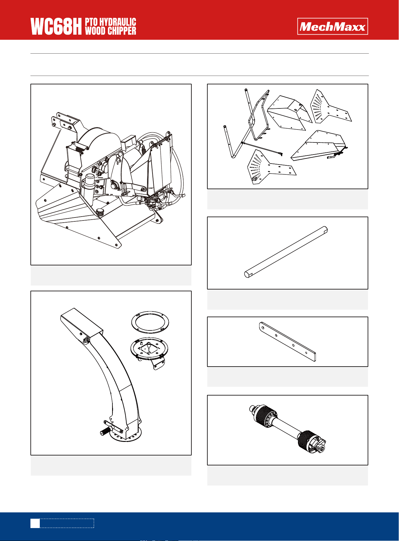
CONTENTS SUPPLIED
CONTENTS SUPPLIED
Base Frame1x
1x
1x
2x
Lower Hitch Arm
Connecting Rod
1x
Infeed Chute
Discharge Chute
1x
PTO Shaft
7
www.mechmaxx.com
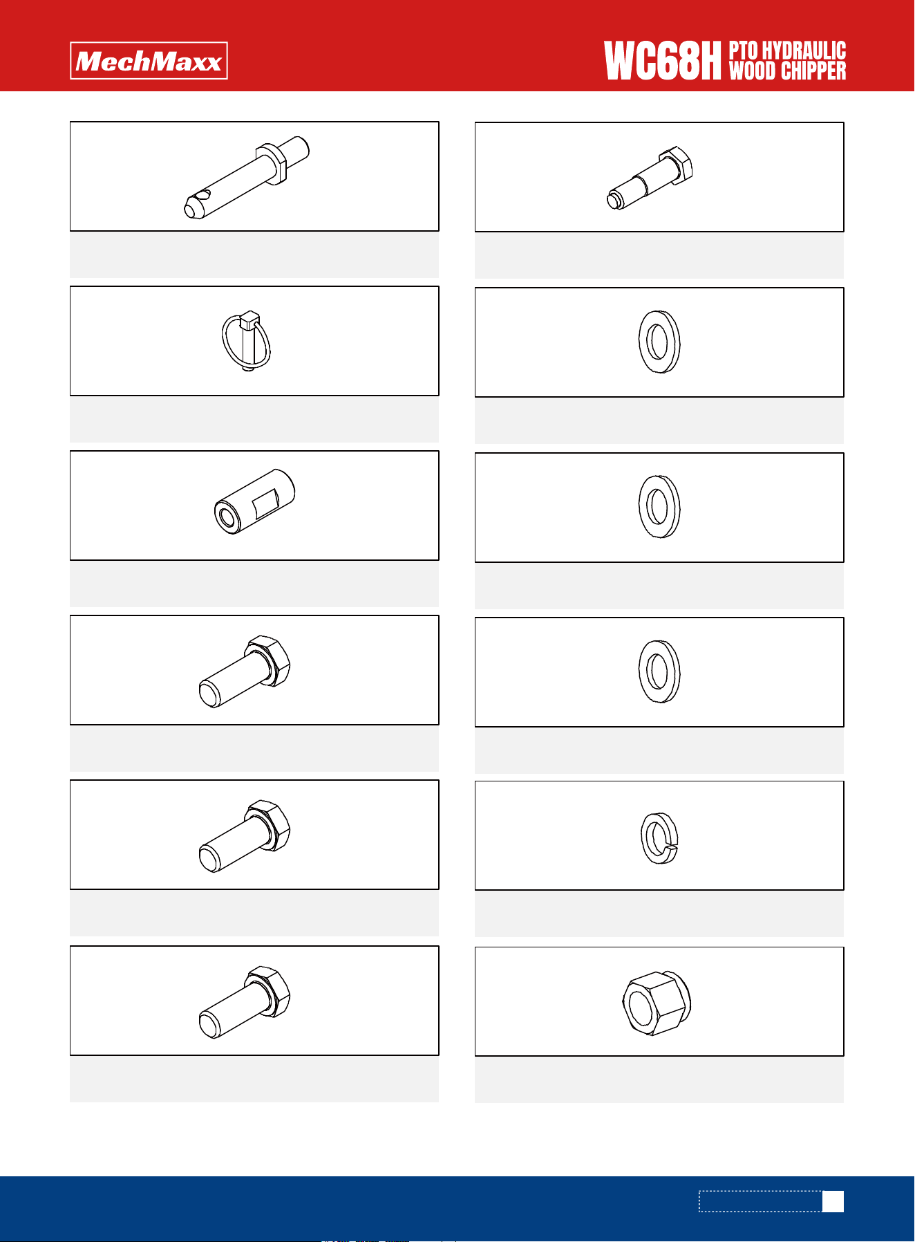
CONTENTS SUPPLIED
2x
Lower Hitch Pin
3x
Linch Pin
2x
Upper Hitch Bushing
4x
M16 X 55 mm Hex Bolt
6x
M16 X 40 mm Hex Bolt
6x
M8 X 30 mm Hex Bolt
2x
M10 X 40 mm Shoulder Bolt
14x
M16 Flat Washer
4x
M10 Flat Washer
18x
M8 Flat Washer
6x
M16 Spring Washer
4x
M16 Lock Nut
8
www.mechmaxx.com
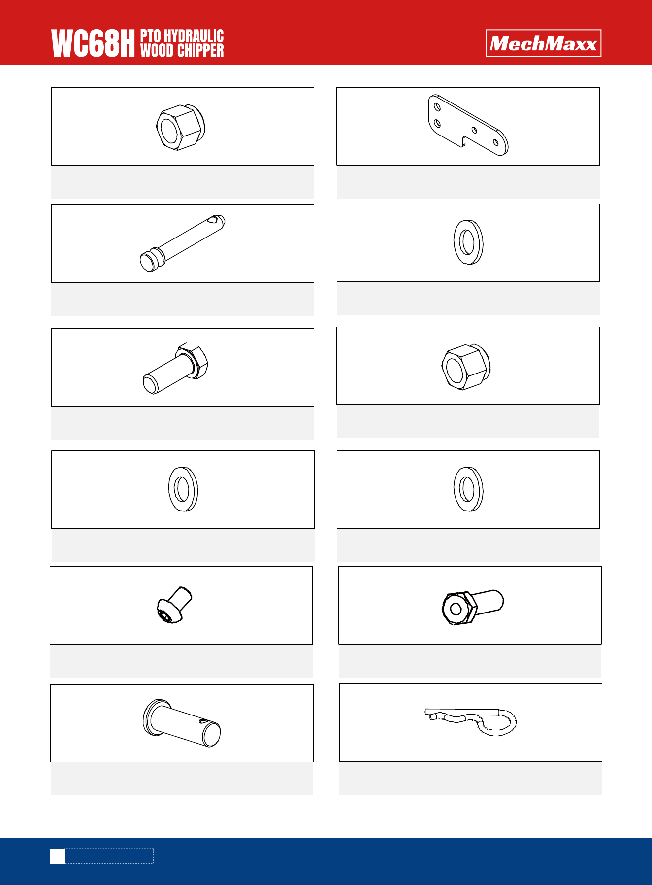
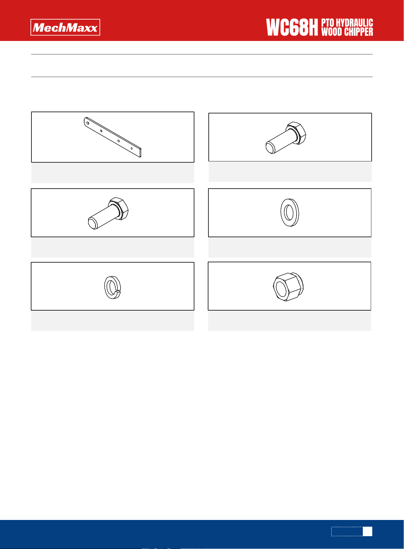
CONTENTS SUPPLIED
2x
M10 Lock Nut
1x Upper Hitch Pin
2x
Upper Hitch Plate
4x
Nylon Flat Washer 10
21x
M8 X 20 mm Hex Bolt
42x
M8 Flat Washer
2x
M10 Flat Washer
21x
M8 Lock Nut
4x
Button Head Screw M10×16
21x
Shaft 15
1x
R Pin 3×50
1x
Pin Shaft 10×30
9
www.mechmaxx.com
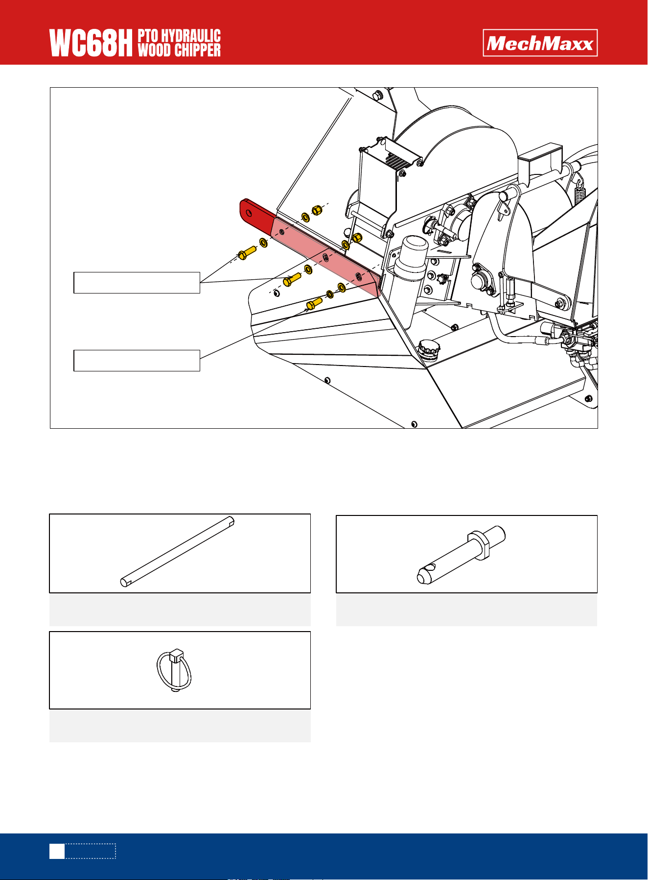
Using the hardware listed below, reorient and then assemble the lower hitch arms.
As shown in the figure, use hex head bolts M16×40, spring washers 16, and flat washers 16 to secure the Lower Hitch
Arm. Then, use hex head bolts M16×55, flat washers 16, and M16 lock nuts to fasten it.
ASSEMBLY
ASSEMBLY
2x
Lower Hitch Arm
LOWER HITCH ARM
4x
M16 X 55 mm Hex Bolt
2x
M16 X 40 mm Hex Bolt
10x
M16 Flat Washer
2x
M16 Spring Washer
4x
M16 Lock Nut
10
www.mechmaxx.com
Note: The Left and Right Lower Hitch Arms are secured using the same bolt installation method.
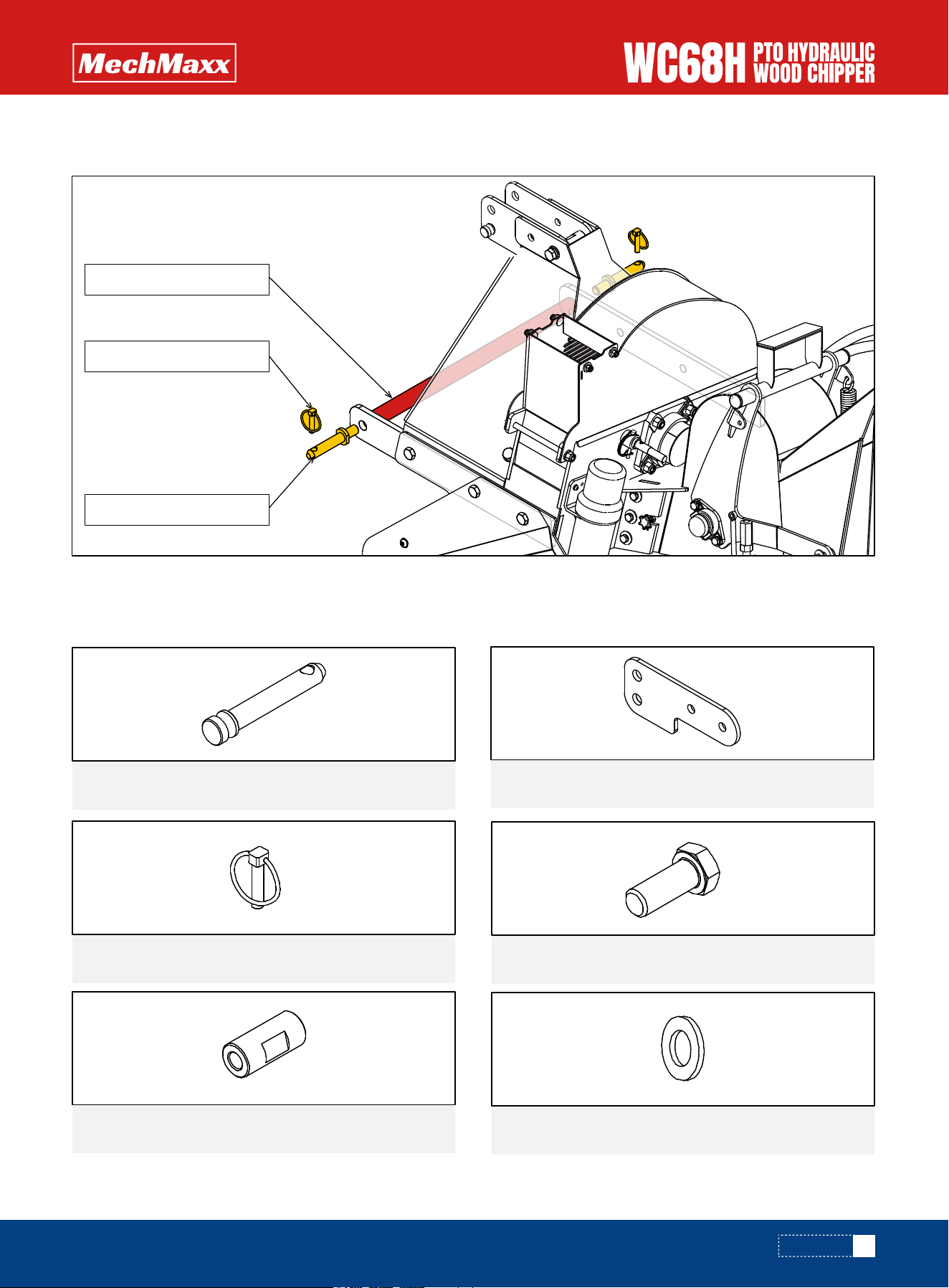
Using the components listed below, assemble the connecting rod and lower hitch pins to the lower hitch arms.
ASSEMBLY
CONNECTING ROD
1x
Connecting Rod
2x
Lower Hitch Pin
2x
Linch Pin
M16 X 55 mm Hex Bolt
M16 X 40 mm Hex Bolt
11
www.mechmaxx.com
Place the Connecting Rod in the middle of the Lower Hitch Arm, and secure it on both sides using a Lower Hitch Pin and
a Linch Pin.
ASSEMBLY
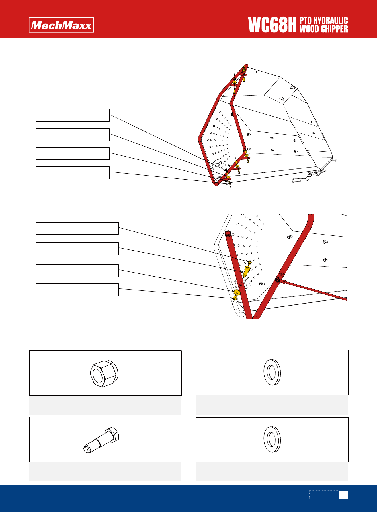
Using the hardware and components listed below, assemble the upper hitch plates to the belt guard.
UPPER HINGE PLATES
1x
Linch Pin
2x
Upper Hitch Bushing
4x
M16 X 40 mm Hex Bolt
4x
M16 Flat Washer
Connecting Rod
Lower Hitch Pin
Linch Pin
1x
Upper Hitch Pin
2x
Upper Hitch Plate
12
www.mechmaxx.com
ASSEMBLY
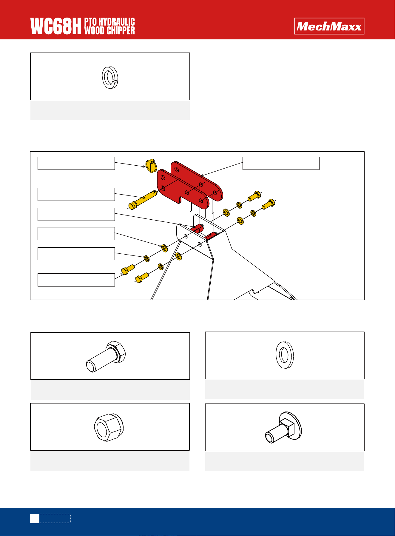
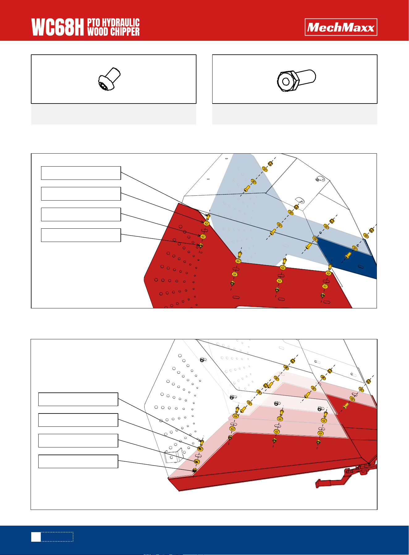
With the components and hardware listed below, assemble the discharge chute to the Base Frame.
Secure the Upper Hitch Plate with an M16 flat washer, an M16 spring washer,and an M16x40 mm Hex Bolt. Insert the
Upper Hitch Bushing in the middle, then install the Upper Hitch Pin and Linch Pin onto the Upper Hitch Plate.
4x
M16 Spring Washer
6x
M8 X 30 mm Hex Bolt
22x
M8 Flat Washer
10x
M8 Lock Nut
4x
M8 X 25 mm Carriage Bolt
Upper Hitch Plate
Linch Pin
Upper Hitch Pin
Upper Hitch Bushing
M16 Flat Washer
M16 Spring Washer
M16x40 mm Hex Bolt
DISCHARGE CHUTE
13
www.mechmaxx.com
M8 X 30 mm Hex Bolt
M8 Flat Washer
Discharge Chute Retainer
M8 Lock Nut
M8 X 25 mm Carriage Bolt
M8 Flat Washer
M8 Lock Nut
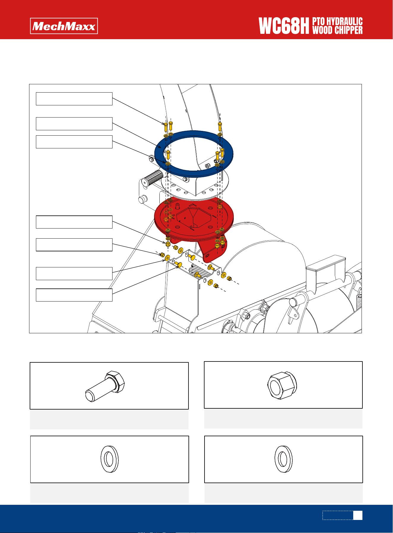
Place the discharge chute into the groove at the top of the nozzle. Use M8×30 mm hex bolts, M8 flat washers, and M8
lock nuts to fasten the discharge chute to the nozzle.
Then use M8×25 mm carriage bolts, M8 flat washers, and M8 lock nuts to secure the discharge chute to the base frame.
Assemble the feed chute using the following parts.
ASSEMBLY
INFEED CHUTE
21x
M8 X 20 mm Hex Bolt
42x
M8 Flat Washer
2x
M10 Flat Washer
21x
M8 Lock Nut
14
www.mechmaxx.com
Use M8 × 20 mm Hex Bolts, M8 Lock Nuts, and M8 Flat Washers to install the left and right side panels of the feed chute
onto the upper section of the chute.
Use M8 × 20 mm Hex Bolts, M8 Lock Nuts, and M8 Flat Washers to install the left and right side panels of the feed chute
onto the lower section of the chute.
ASSEMBLY
4x
Button Head Screw M10×16
2x
Shaft 15
M8 Lock Nut
M8 X 20 mm Hex Bolt
M8 Flat Washer
M8 Flat Washer
M8 Lock Nut
M8 X 20 mm Hex Bolt
M8 Flat Washer
M8 Flat Washer
15
www.mechmaxx.com
CONTROL ARM LINKAGE
Use M8 × 20 mm Hex Bolts, M8 Lock Nuts, and M8 Flat Washers to install the guard bar onto the feed chute.
Use M8 Flat Washers, M10×16 Button Head Screws, and Shaft 15 to install the emergency stop lever onto the feed
chute.
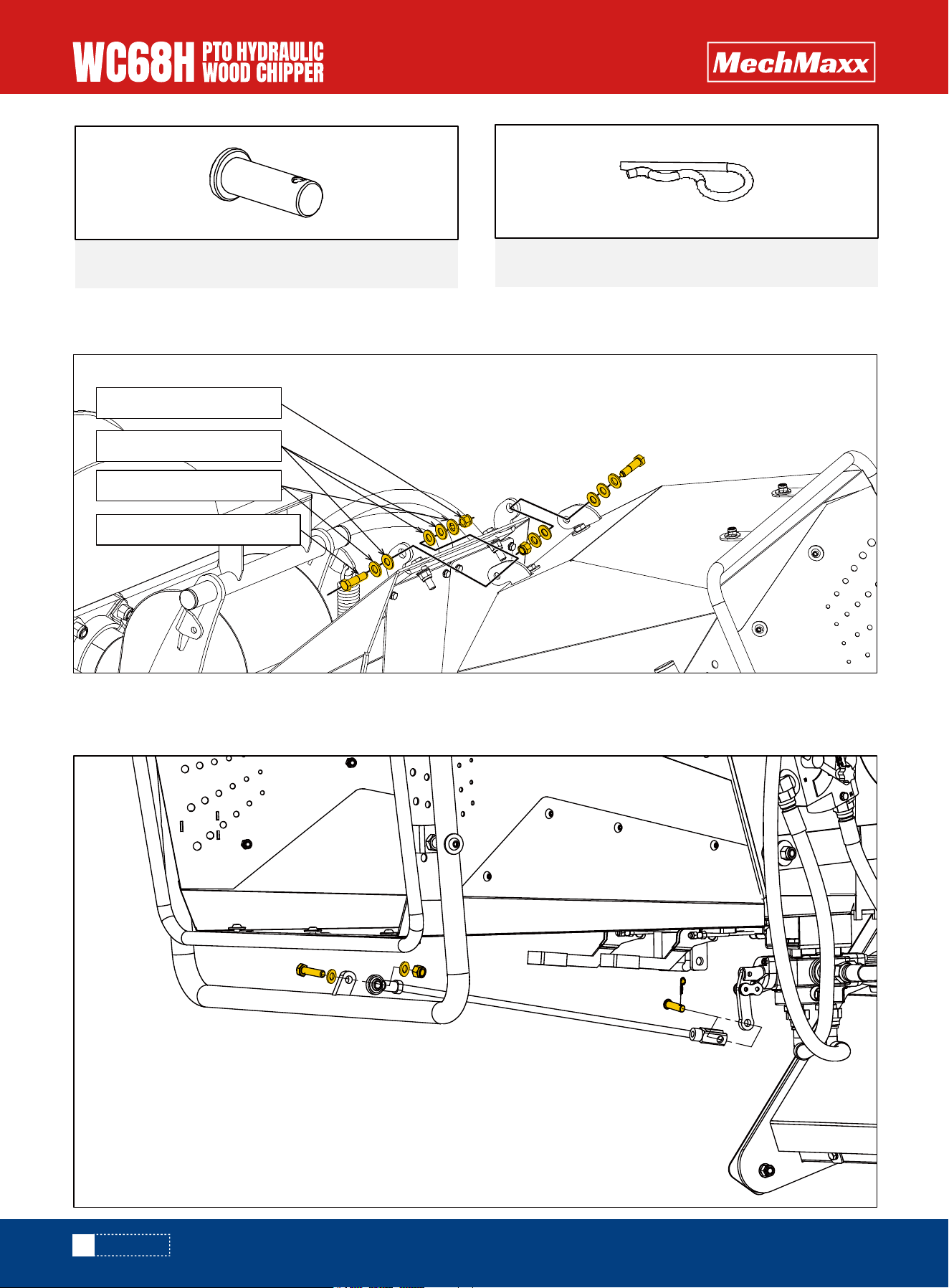
Use the following parts to install the feed chute onto the machine.
ASSEMBLY
2x
M10 X 40 mm Shoulder Bolt
6x
M10 Flat Washer
6x
Nylon Flat Washer 10
3x
M10 Lock Nut
M8 Lock Nut
M8 X 20 mm Hex Bolt
M8 Flat Washer
M8 Flat Washer
Button Head Screw M10×16
Button Head Screw M10×16
Shaft 15
M10 Flat Washer
16
www.mechmaxx.com
Use an M10 Lock Nut, M10 Flat Washer, M10 × 40 mm Shoulder Bolt, and Nylon Flat Washer 10 to attach the upper part
of the feed hopper to the chipper.
Use the safety lock on the feed hopper to secure it to the chipper, and then connect the emergency stop linkage using an
M10 Hex Nut, M10 Flat Washer, and M10 × 40 Bolt.
Then use a 10×30 Pin Shaft and a 3×50 R Pin to connect the end of the linkage.
ASSEMBLY
1x
R Pin 3×50
1x
Pin Shaft 10×30
M10 Lock Nut
Nylon Flat Washer 10
M10 X 40 mm Shoulder Bolt
M10 Flat Washer
17
www.mechmaxx.com
OPERATION
OPERATION
It is the responsibility of the owner or operator to read
this manual and to train all other operators before they
start working with the machine. Follow all safety instruc-
tions exactly. Safety is everyone's business.
By following recommended procedures, a safe working
environment is provided for the operator, bystanders, and
the area around the worksite. Untrained operators are not
qualified to use the machine.
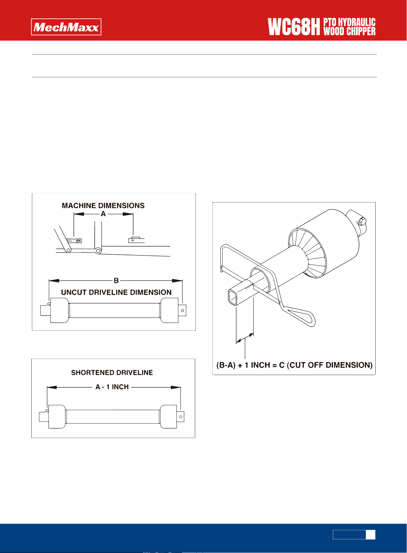
1. To determine the proper length of the drive line, follow
this procedure:
a. Clear the area of bystanders, especially small children.
b. Attach the chipper to the tractor but do not attach the
drive line.
c. Raise the machine until the input shaft is level with
the tractor PTO shaft.
d. Measure the dimension between the locking grooves
on the tractor PTO shaft and the machine input shaft.
e. Measure the same dimensions on the compressed
drive line.
f. If the compressed drive line dimension exceeds the
machine dimension, the drive line will have to be cut.
2. When cutting the drive line, follow this procedure:
a. Subtract the machine dimension (A) from the uncut
drive line dimension (B) or (B-A). This dimension deter-
mines how much too long the drive line is.
b. Add another inch (25 mm) to the dimension to be sure
it doesn't bottom out, to determine (C) the cut off dimen-
sion.
c. Use a hacksaw to cut dimension (C) from both ends.
Cut both the plastic tubes and the metal cores.
d. Use a file to remove the burrs from the edges that
were cut.
e. Assemble the 2 ends of the shaft.
OPERATION
SEPARATE PTO HALVES

18
www.mechmaxx.com
OPERATION
f. Make sure the shaft can telescope freely. If it does
not, separate the 2 parts and inspect for burrs or
cuttings on the shaft ends. Be sure it telescopes freely
before installing.
Note: Failure to perform this procedure may result in
severe damage to the implement, which is not covered
under warranty.
The Wood Chipper is a strong, rugged machine that is
built to a straightforward design which provides consis-
tent chipping of logs up to 6" (152mm)
Always wear personal protective equipment (PPE) when-
ever operating the machine. This includes but is not
limited to protective shoes with slip resistant soles,
protective goggles or face shield, heavy gloves, hearing
protection and protective clothing.
Do not place metal, bottles, cans, rocks, glass or other
solid material into the wood chipper. If something like
this gets into the machine, stop the machine immediate-
ly for a detailed inspection. Stop engine, remove ignition
key and place in your pocket and wait for all moving parts
to stop before inspecting or unplugging. Inspect machine
for damaged or loosened parts before resuming work.
Caution and care should be exercised when feeding
material into the feeder. Do not reach into the hopper
past the curtain barrier.
a. Before beginning to feed the rotor is up to speed.
b. Slowly slide the wooden material into the feed hopper
and move it into the rotor.
c. Do not force the material into the rotor, as the material
engages the rotor, the rotor will draw the material in. Use
continuous lite pressure to guide in the material.
d. Be aware of how much material you feed in, slow down
or stop if the rotor begins to slow down.
e. Do not reach into the feed hopper further than the
curtain to be sure not to contact the blades on the rotor.
f. Use a stick or branch to push any piece of material into
the rotor that does not move on its own. If the jam
persists then stop the engine and wait for the rotor to
stop and then clear the jam. Do not take a chance with
getting your hand caught in the rotor.
g. Ensure your wood chip pile is contained and doesn't
affect the immediate work area.
Although the machine is designed to handle a wide
variety of material without any problem, occasionally it
plugs. When the machine plugs, follow this procedure to
unplug:
a. Clear the area of bystanders, especially small children.
b. Turn off the hydraulics, stop the engine, remove the
ignition key and place it in your pocket and wait for all
moving parts to stop before unplugging.
c. Pull the material out of the feed hopper. Be sure all the
material is out, and nothing is jammed or wedged
between the input opening and the rotor.
d. Pull the material out of the discharge hood. Use a stick
to poke loose any material jammed into the discharge
hood. Do not allow anything to remain in this area.
e. Check that everyone is clear of machine before
restarting engine.
f. Start the engine turn on the hydraulics, and resume
working.
a. Clear the area of bystanders, especially small children.
b. Turn off the hydraulics, stop the engine, remove the
ignition key and place it in your pocket or remove spark
plug wire, and wait for all moving parts to stop before
unplugging.
c. Loosen the feed hopper anchor nuts and raise the feed
hopper.
d. Remove jammed material from inside the rotor
compartment.
CHIPPING OPERATION
UNPLUGGING
SEVERE PLUG
19
www.mechmaxx.com
OPERATION
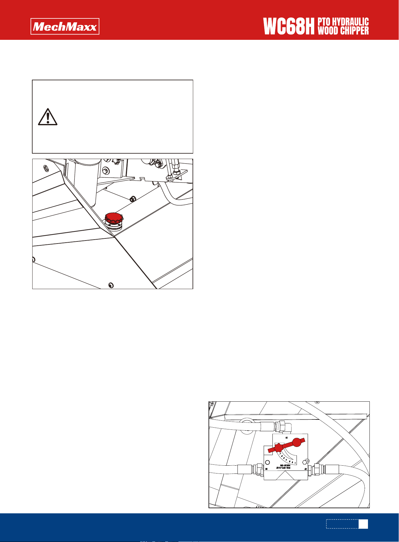
USE PLASTIC GLOVES TO KEEP OIL OFF
SKIN AND DISPOSE OF THE USED OIL
AND FILTER IN AN ECOLOGICALLY
SOUND WAY. THE OIL AND FILTER
SHOULD BE CHANGED ONCE A YEAR OR
AT ANY TIME IT BECOMES CONTAMI-
NATED.
*Shipped with NO fluids. Must add own fluid
Top up with ISO 32, ISO 46, AW 32, AW 46 hydraulic oil.
Avoid overfilling.
1. Place the tractor transmission in neutral, apply the
parking brake, and shut off the tractor engine.
2. Attach the three-point hitch to the wood chipper and
secure it with the hitch pins.
3. Adjust the top link of the three-point hitch so that the
wood chipper sits level.
4. Connect the PTO shaft to the tractor, attaching the
shear bolt end to the wood chipper. Ensure that the PTO
safety chains are properly connected to both the tractor
and the wood chipper to prevent the protective PTO
guard from rotating.
5. Rotate the discharge chute to a safe direction and
lock it in place using the spring-loaded latch and the
positioning hole. Adjust the deflector to the desired
position according to the required discharge distance.
6. Start the tractor engine and maintain a strong idle
speed. Engage the PTO slowly. Engaging the PTO at high
engine speed may damage the drive belt or shear bolt on
the PTO shaft. Once the rotor spins freely, gradually
increase the tractor engine speed until the PTO reaches
540 rpm. Most tractor tachometers indicate this speed
with a line and/or marking.
7. When the wood chipper is running and the feed rollers
are turning, you may begin chipping. Start with small-di-
ameter branches until you become familiar with the
machine and its operation. Once comfortable, you can
begin feeding larger branches.
Never leave the wood chipper unattended, and never
perform inspection or maintenance work while the PTO
shaft is engaged or the tractor engine is running. Allow
sufficient time for the wood chipper to come to a
complete stop.
To stop the wood chipper, follow the steps below:
1.Move the tractor throttle to the slow/idle position.
2.Disengage the PTO lever and shut off the tractor
engine.
3.Allow adequate time for the wood chipper to come to a
complete stop.
Note: Even after the tractor or engine has been shut off,
the flywheel will continue to rotate for a short period. The
flywheel has stopped when no sound or vibration from
the machine can be heard or felt. The PTO shaft will also
have stopped rotating.
The number “1” indicates that the infeed rollers are
stopped, while “10” represents full operating speed. For
maximum productivity and optimal performance, it is
recommended to operate at full infeed speed during
chipping.
HYDRAULIC OIL
START UP
STOPPING
INFEED ROLLER CONTROL
20
www.mechmaxx.com
OPERATION
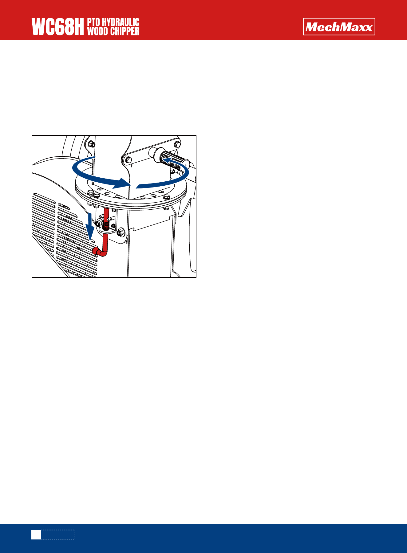
To rotate the discharge chute, fully press down the
spring-loaded locking pin and turn it 90° to temporarily
hold it in the open position. This will allow the chute to
rotate freely through 360°. Use the handles to turn the
chute to the desired direction, then rotate the locking pin
back 90° so it engages the nearest locking hole to secure
the chute firmly in place.
DISCHARGE CHUTE
21
www.mechmaxx.com
MAINTENANCE
MAINTENANCE
By following a careful service and maintenance program
for your machine, you will enjoy many years of trouble-free
operation.
The rotor and ledger blades need to be sharp for the
Chipper to perform as expected. Periodic inspection is
recommended. Keep the blades sharp to reduce the
amount of power required during operation. Watch the
sharpness of the blades when processing material with a
lot of sand, soil or dirt mixed with it. Reverse or sharpen
the blades if the cutting edge becomes dull. Twig breaker
should be inspected for gouges or bent.
The rotor is equipped with 4 blades spaced evenly to keep
the rotor in balance. If one needs to be changed, the one
opposite should also be changed.
1. Turn off the hydraulics, stop the engine, remove the
ignition key, and place it in your pocket and wait for all
moving parts to stop.
2. Remove the bolt that secures the upper rotor housing,
and carefully open the rotor housing.
3. Manually rotate chipper rotor plate so that the blade is
fully exposed.
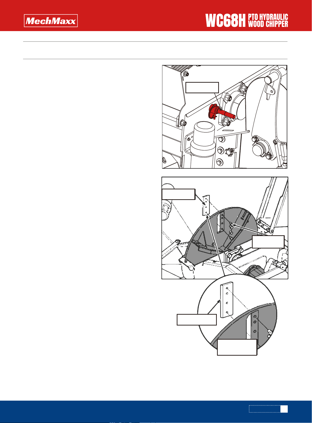
4. Rotate the flywheel until one of the locking holes near
the front edge of the blade is roughly aligned with the
flywheel lock pin at the rear of the housing. Remove the
round retaining pin from the flywheel lock pin, then rotate
the lock pin 180° and insert it through the housing into
the corresponding locking hole on the primary flywheel.
5. Remove the bolts that hold the rotor blade to the rotor,
remove the blade.
6. Rotate the blade and reinstall or replace with new or
resharpened blade.
7. Ensure the blade is properly oriented, with the leading
edge out. The blade is designed to fit into the rotor one
way only. See diagram for proper installation.
8. Tighten down bolts as specified in the torque chart.
9. Repeat steps for remaining blades.
BLADE AND BREAKER MAINTENANCE
ROTOR BLADES MAINTENANCE
Rotor Blade
Lock Pin
Loading Edge
Proper orientation
of Rotor Blade
Rotor Blade
Bolts
22
www.mechmaxx.com
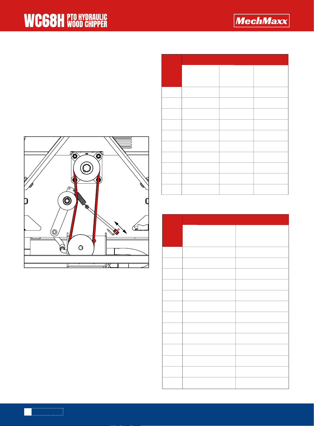
Check the belt’s condition and tension every 30 hours of
operation. The belt is automatically tensioned by an
extension spring, but the tension can be adjusted if
necessary by following these steps:
1.Check the pump belt tension by pressing it with your
finger. The belt should have no slack and remain under
firm tension.
2.If additional tension is needed, adjust the lower
right-side eyebolt by loosening or tightening the hex nuts
as shown below. This will stretch the spring and increase
the belt tension until it is firm.
CHECKING BOLT TORQUE
The tables shown below give correct torque values for
various bolts and cap screws. Tighten all bolts to the
torques specified in chart unless otherwise noted. Check
tightness of bolts periodically, using bolt torque chart as
a guide. Replace hardware with the same strength bolt.
Torque figures indicated above are valid for non-greased
or non-oiled threads and heads unless otherwise speci-
fied. Therefore, do not grease or oil bolts or cap screws
unless otherwise specified in this manual. When using
locking elements, increase torque values by 5%.
* Torque value for bolts and cap screws are identified by
their head markings
ADJUSTING BELT TENSION
BOLT TORQUE
Bolt
Diameter
Bolt
Diameter
SAE 2
N.m lb-ft N.m lb-ft N.m lb-ft
SAE 5 SAE 8
Bolt Torque
1/4"
5/16"
3/8"
7/16"
1/2"
9/16"
5/8"
3/4"
7/8"
1"
8
13
27
41
61
95
128
225
230
345
6
10
20
30
45
60
95
165
170
225
12
25
45
72
110
155
215
390
570
850
9
19
33
53
80
115
160
290
420
630
17
36
63
100
155
200
305
540
880
1320
12
27
45
75
115
165
220
400
650
970
ENGLISH TORQUE SPECIFICATIONS
8.8
N.m lb-ft N.m lb-ft
10.9
Bolt Torque
M3
M4
M5
M6
M8
M10
M12
M14
M16
M20
M24
M30
M36
0.5
3
6
10
25
50
90
140
225
435
750
1495
2600
0.4
2.2
4
7
18
37
66
103
166
321
553
1103
1917
1.8
4.5
9
15
35
70
125
200
310
610
1050
2100
3675
1.3
3.3
7
11
26
52
92
148
229
450
744
1550
2710
METRIC TORQUE SPECIFICATIONS
MAINTENANCE

23
www.mechmaxx.com
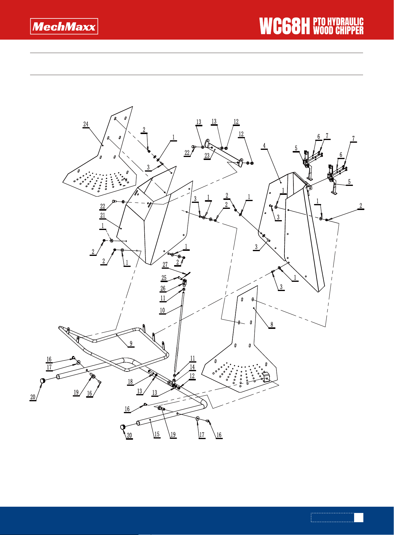
PARTS DIAGRAM
PARTS DIAGRAM

24
www.mechmaxx.com
4
1
4
1
1
1
4
1
1
6
1
16
1
14
4
6
6
4
8
2
2
2
1
1
1
8
2
3
Parts# Description Quantity
1
2
3
4
5
6
7
8
9
10
11
12
13
14
15
16
17
18
19
20
21
22
23
24
25
26
27
28
Spring Washer 6
Suction Pipe Weldment
Hex Socket Cap Screw M6×20
O-Ring 50×3.55
Suction Oil Filter
Fuel Tank Weldment
Hex Socket Cap Screw M4×12
Air Filter
Hex Head Bolt M8×45
Flat Washer 8
Straight Connector
Flat Washer 10
Fuel Tank Plug M20×1.5
Flat Washer 16
Full Thread Hex Head Bolt M16×50
Thick Flat Washer φ10×20×3
Nylon Insert Hex Lock Nut M16
Hex Socket Button Head Screw M10×12
Hex Socket Button Head Screw M10×25
Spring Washer 16
Full Thread Hex Head Bolt M16×40
Full Thread Hex Head Bolt M16×45
Left Base Guard
Base Weldment
Right Base Guard
Nylon Insert Hex Lock Nut M10
Hex Head Bolt M8×55
Nylon Insert Hex Lock Nut M8
PARTS LIST
PARTS LIST
25
www.mechmaxx.com
PARTS DIAGRAM
PARTS DIAGRAM

26
www.mechmaxx.com
42
21
21
1
2
8
8
1
1
1
2
3
6
1
1
4
2
1
2
2
1
2
1
1
1
1
1
Parts# Description Quantity
1
2
3
4
5
6
7
8
9
10
11
12
13
14
15
16
17
18
19
20
21
22
23
24
25
26
27
Large Flat Washer 8
Nylon Insert Hex Lock Nut M8
Hex Socket Button Head Screw M8×20
Infeed Housing Bottom Plate Weldment
Quick Clamp
Spring Washer 6
Cross Recess Pan Head Screw M6×10
Infeed Housing Right Side Plate A Weldment
Frame Round Bar Weldment
Double-End Stud 670
Hex Nut M10
Nylon Insert Hex Lock Nut M10
Flat Washer 10
Rod End Bearing M10×1.5
Control Arm Weldment
Hex Socket Button Head Screw M10×16
Large Flat Washer 10
Full Thread Hex Head Bolt M10×40
Shaft 15
Round Tube End Cap
Infeed Housing Front Panel W
Full Thread Hex Head Bolt M10×25
Infeed Opening Panel Hook Weldment
Infeed Housing Left Side Plate A Weldment
Pin Shaft 10×30
Y Fitting Y32-M10×1.5
R Pin 3×50
PARTS LIST
PARTS LIST

27
www.mechmaxx.com
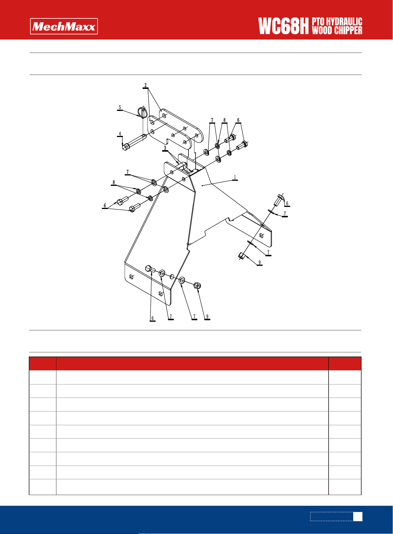
PARTS DIAGRAM
PARTS DIAGRAM
1
11
11
11
11
1
1

28
www.mechmaxx.com
3
12
7
6
10
2
6
8
1
1
4
1
18
6
2
3
2
4
2
1
1
1
1
1
4
1
4
1
Parts# Description Quantity
1
2
3
4
5
6
7
8
9
10
11
12
13
14
15
16
17
18
19
20
21
22
23
24
25
26
27
28
Eye Bolt M10×130
Flat Washer 8
Spring Washer 10
Nylon Insert Hex Lock Nut M8
Nylon Insert Hex Lock Nut M6
Full Thread Hex Head Bolt M8×20
Hex Nut M10
Flat Washer 10
Straight Connector 1CT-22-08
Control Valve
Full Thread Hex Head Bolt M10×16
Xinyuan Manual Tube B
Flat Washer 6
Spring Washer 6
Curtain
Hex Socket Button Head Screw M6×16
Nylon Insert Hex Lock Nut M10
Full Thread Hex Head Bolt M6×20
Full Thread Hex Head Bolt M10×30
Clamp Plate
Warning Plate
Pressure Plate
D-Shaped Lock Pin 6×60
Cutter Disc Lock Pin
Full Thread Hex Head Bolt M8×12
Knife Adjusting Plate Weldment
Spring Washer 8
Tee Fitting G1/2–M22×1.5
PARTS LIST
PARTS LIST

29
www.mechmaxx.com
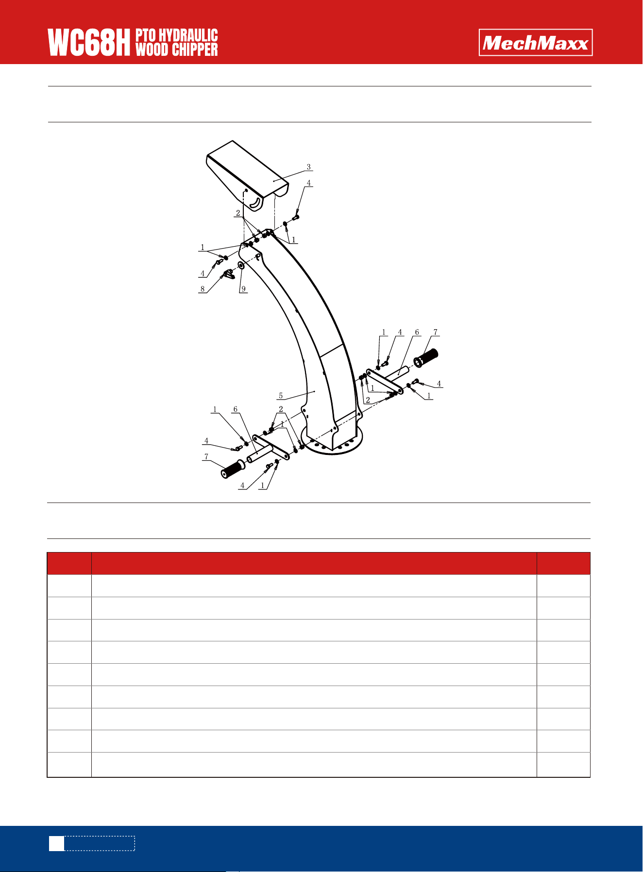
4
1
1
2
2
2
2
6
2
1
1
3
1
2
2
2
1
1
4
1
3
1
3
1
1
1
1
Parts# Description Quantity
29
30
31
32
33
34
35
36
37
38
39
40
41
42
43
44
45
46
47
48
49
50
51
52
53
54
55
Cross Recess Pan Head Screw M6×16
Chipping Chamber Weldment
Elbow 1CG9-22-080G
Hex Socket Button Head Screw M12×50
Spacer 12×28
Nylon Insert Hex Lock Nut M12
Large Flat Washer 12
Straight Connector 1CB-22-08WD
Hex Head Bolt M6×65
Flow Control Valve
Stop Plate Weldment
Full Thread Hex Head Bolt M6×12
Feed Roller Cover Plate
Safety Pin 10×45
Lower Link Pin
Lower Link Arm
Nylon Insert Hex Lock Nut M16
Pin Shaft 16
Full Thread Hex Head Bolt M8×35
Connecting Rod
Large Flat Washer 10
Fixed Blade
Full Thread Hex Head Bolt M10×25 (Grade 12.9)
Hex Nut M8
Star Handle M8×30
Gear Pump
Straight Connector 1CT-26-08
PARTS LIST

30
www.mechmaxx.com
PARTS DIAGRAM
16
4
1
16
4
1
4
2
8
8
8
1
Parts# Description Quantity
1
2
3
4
5
6
7
8
9
10
11
12
Hex Socket Countersunk Screw M10×35
Moving Blade 220×70×8
Cutter Disc Weldment
Nylon Insert Hex Lock Nut M10
Nylon Insert Hex Lock Nut M16
Splined Shaft 6×28×34.85×8.6
Hex Socket Countersunk Screw M16×60
Square Flange Bearing
Non-metallic Insert Hex Lock Nut M14
Flat Washer 14
Socket Countersunk Head Screw M14×45
Bearing Protection Cover 210
PARTS LIST
PARTS DIAGRAM
31
www.mechmaxx.com
PARTS DIAGRAM
1
2
2
1
1
6
8
4
2
Parts# Description Quantity
1
2
3
4
5
6
7
8
9
Belt Guard Weldment
Upper Link Plate
Connecting Rod 23×64
Upper Link Pin
Safety Pin 10×45
Full Thread Hex Head Bolt M16×40
Flat Washer 16
Spring Washer 16
Nylon Insert Hex Lock Nut M16
PARTS LIST
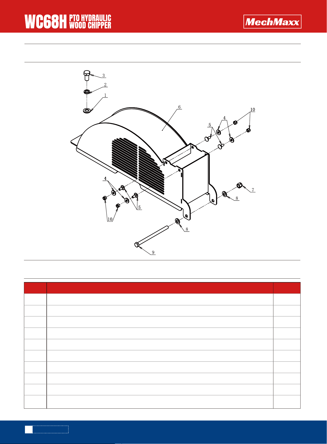
PARTS DIAGRAM
32
www.mechmaxx.com
PARTS DIAGRAM
1
1
1
4
4
1
1
2
1
4
Parts# Description Quantity
1
2
3
4
5
6
7
8
9
10
Flat Washer 16
Spring Washer 16
Full Thread Hex Head Bolt M16×30
Large Flat Washer 8
Large Semi-Round Neck Bolt M8×20
Cutter Disc Upper Housing Weldment
Nylon Insert Hex Lock Nut M12
Flat Washer 12
Hex Head Bolt M12×180
Nylon Insert Hex Lock Nut M8
PARTS LIST
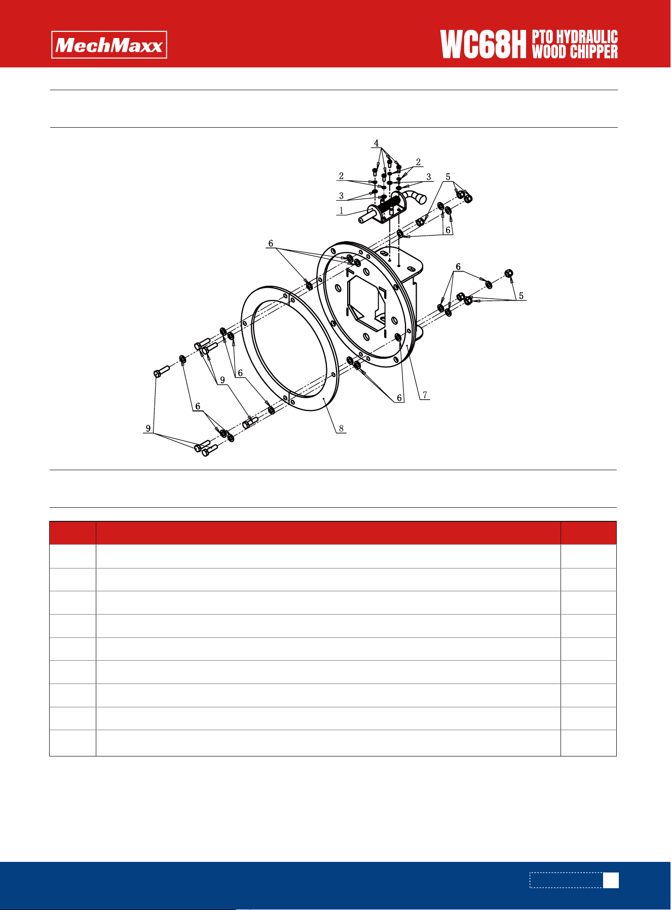
PARTS DIAGRAM
33
www.mechmaxx.com
PARTS DIAGRAM
1
4
4
4
6
18
1
2
6
Parts# Description Quantity
1
2
3
4
5
6
7
8
9
Spring Pin
Spring Washer 5
Flat Washer 5
Cross Recess Pan Head Screw M5×12
Nylon Insert Hex Lock Nut M8
Flat Washer 8
Discharge Opening Weldment
Discharge Flange Support Plate
Full Thread Hex Head Bolt M8×30
PARTS LIST
PARTS DIAGRAM
34
www.mechmaxx.com
PARTS DIAGRAM
12
6
1
6
1
2
2
1
1
Parts# Description Quantity
1
2
3
4
5
6
7
8
9
Flat Washer 8
Nylon Insert Hex Lock Nut M8
Discharge Chute Adjustment Plate
Full Thread Hex Head Bolt M8×20
Discharge Chute Weldment
Discharge Chute Handle Weldment
Handle Grip
Adjustable Handle AM10×80
Large Flat Washer 10
PARTS LIST
PARTS DIAGRAM
PARTS DIAGRAM
35
www.mechmaxx.com
PARTS DIAGRAM

1
2
2
2
2
1
2
1
2
1
1
2
2
1
1
1
2
2
2
1
1
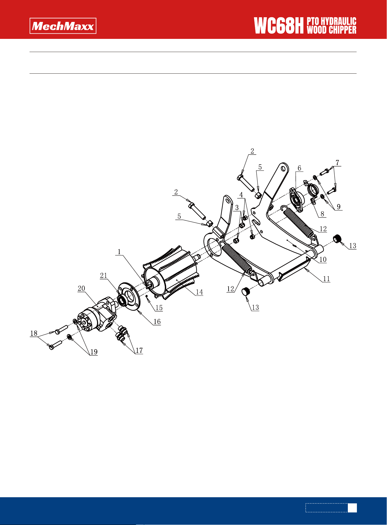
Parts# Description Quantity
1
2
3
4
5
6
7
8
9
10
11
12
13
14
15
16
17
18
19
20
21
Key A Type 8×25
Full Thread Hex Head Bolt M16×80
Nylon Insert Hex Lock Nut M12
Nylon Insert Hex Lock Nut M10
Hex Nut M16
Bearing with Diamond Base UCFLU204
Full Thread Hex Head Bolt M10×35
Bearing Protective Cover Weldment 204
Flat Washer 10
Rocker Arm Weldment
Rocker Arm Rubber Pad
Tension Spring 33×5
Round Tube End Cap 33
Feed Roller Weldment A
Hex Socket Set Screw M6×6
Motor Bearing Plate
Straight Connector
Full Thread Hex Head Bolt M12×55
Flat Washer 12
Hydraulic Motor
Deep Groove Ball Bearing
PARTS LIST
36
www.mechmaxx.com
PARTS LIST
37
www.mechmaxx.com
PARTS DIAGRAM
1
1
1
1
1
1
1
1
1
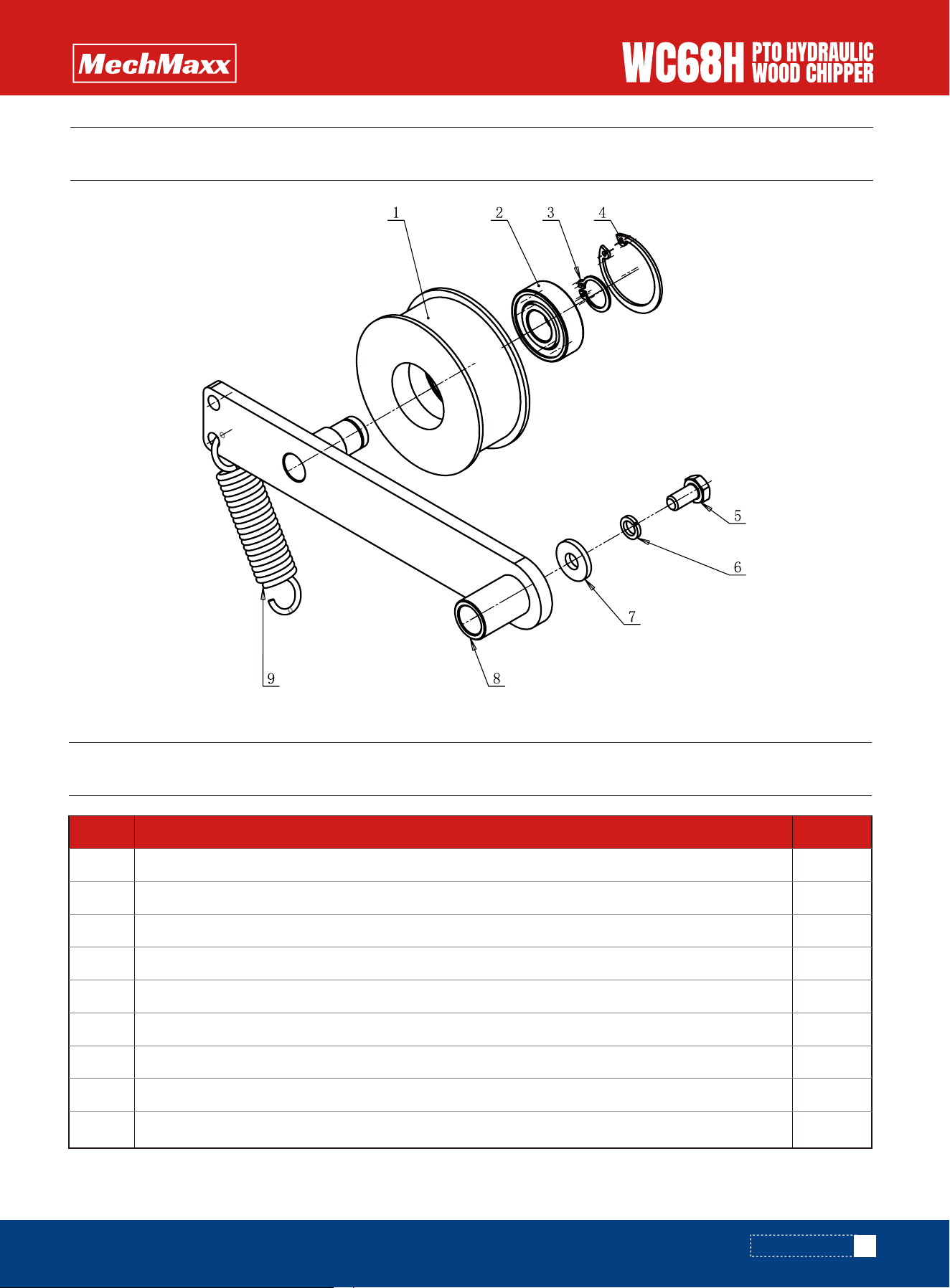
Parts# Description Quantity
1
2
3
4
5
6
7
8
9
Idler Pulley
Deep Groove Ball Bearing
Shaft Retaining Ring A Type 17
Bore Retaining Ring A Type 40
Full Thread Hex Head Bolt M8×16
Spring Washer 8
Large Flat Washer 8
Belt Tension Arm Weldment
Tension Spring 21×3
PARTS LIST
PARTS DIAGRAM