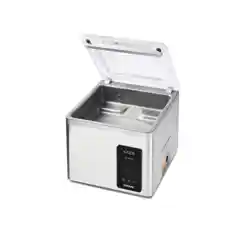

Vacuum Packaging Machine
Kaze
User Manual
Art No. 0894638
Original Instructions for Use
©
Eurodib 2022

• The machine is not suitable for the packaging of toxic, corrosive, irritant or potentially
explosive materials.
• All persons responsible for the operation of this machine must at least fully read and
understand the chapters about the operation and safety provided in these operating
instructions.
• All persons responsible for the assembly, installation, maintenance and/or repairs must
fully read and understand these operating instructions.
• The user is at all times responsible for the interpretation and use of this manual.
Contact the owner or the manager in case of questions or doubts about the correct
interpretation.
• This manual should be kept near the machine and should be within reach for its users.
• All major maintenance work, modifications to the machine and observations must be
kept in a logbook; see Logbook on page 47.
• Modifications to the installation/machine are not allowed without the prior written
consent of the supplier. Such modifications will invalidate the ETL Certification.
• For specific maintenance work not included in this manual, please contact the supplier.
• Comply with the safety requirements as set out in Safety on page 9 at all times.
• The correct operation and safety of the system can only be guaranteed if the
recommended maintenance is performed on time and properly.
• Illustrations shown may differ from your machine.
Copyright
©
Eurodib 2022
Eurodib reserves the right to change specifications and/or spare parts without prior notice.
The content of this user manual may also be changed without prior notice.
For information about settings, maintenance and repairs not provided for in this user manual, please contact the technical department of your supplier.
Eurodib accepts no liability for damage and/or problems arising from the use of spare parts not supplied by Eurodib.
This user manual has been compiled with all possible care. Eurodib assumes no responsibility for any errors in this manual and/or the consequences of an
erroneous interpretation of the instructions.
All rights reserved. No part of this publication may be reproduced, stored in computerised databases, or made public, in any form or by any means, either
electronic, mechanical, through photocopying, recording or otherwise, without the prior written consent of Eurodib. This also applies to the associated
drawings and diagrams.

Contents
List of Figures................................................................................................................................. 5
1 Preamble....................................................................................................................................... 6
1.1 List of the Symbols Used in this Manual............................................................................... 6
1.2 Qualified personnel................................................................................................................ 6
1.3 Storing the manual.................................................................................................................7
1.4 Regulatory information........................................................................................................... 7
1.5 Terms of Warranty..................................................................................................................7
1.6 Liability....................................................................................................................................7
1.7 Terms and abbreviations........................................................................................................8
2 Safety.............................................................................................................................................9
2.1 Pictograms on the Machine................................................................................................... 9
2.2 General Warnings.................................................................................................................. 9
2.3 Warnings During Use...........................................................................................................10
2.4 Warnings for Operating Personnel.......................................................................................11
3 Introduction.................................................................................................................................12
4 Description of the Machine.......................................................................................................13
4.1 Kaze series...........................................................................................................................13
4.1.1 Overview of the Main Components..............................................................................14
4.2 Description of the Packaging Process/Machine Functions.................................................. 15
4.2.1 Packaging Process/Machine Functions........................................................................15
4.2.2 General Functions........................................................................................................ 16
4.3 Sealing System.................................................................................................................... 17
5 Installation...................................................................................................................................18
5.1 Transportation and Installation............................................................................................. 18
5.2 Connecting the Machine...................................................................................................... 18
5.3 Prior to the First Use........................................................................................................... 19
6 Operation.....................................................................................................................................20
6.1 Kaze Control System........................................................................................................... 20
6.1.1 Operating Elements......................................................................................................20
6.1.2 Starting the Machine.................................................................................................... 21
6.1.3 Starting the Packaging Cycle.......................................................................................21
6.1.4 Proceeding to the Next Step in the Cycle....................................................................21
6.1.5 Terminating a Program.................................................................................................21
6.1.6 Changing the Program Settings (manual)....................................................................22
6.1.7 Changing the Program Settings (automatic)................................................................22
6.1.8 Program Settings Parameters...................................................................................... 23
6.1.8.1 Vacuum.................................................................................................................23
6.1.8.2 Liquid Control (optional)....................................................................................... 23
Contents 3

6.1.8.3 Vacuum+ time (optional).......................................................................................24
6.1.8.4 Seal.......................................................................................................................24
6.1.8.5 Red Meat (optional)..............................................................................................25
6.1.8.6 Soft Air..................................................................................................................25
6.1.9 Example programs....................................................................................................... 25
6.1.10 Guidelines for Function Values.................................................................................. 26
6.1.11 Changing the Machine Settings................................................................................. 27
6.1.11.1 Settings...............................................................................................................28
6.1.11.2 Service................................................................................................................29
6.1.11.3 Import..................................................................................................................29
6.1.11.4 External Vacuum (optional)................................................................................ 30
7 Maintenance................................................................................................................................31
7.1 Maintenance Schedule.........................................................................................................31
7.2 Cleaning the Machine.......................................................................................................... 32
7.3 Replacing the Sealing Wire................................................................................................. 32
7.4 Replacing the Silicone Rubber of the Silicone Holders....................................................... 34
7.5 Replacing the Lid Gasket.....................................................................................................35
7.6 Inspecting the Lid Springs................................................................................................... 35
7.7 Vacuum Pump maintenance................................................................................................ 36
7.7.1 Overview.......................................................................................................................36
7.7.1.1 Pump 10 m
3
/h (338 cf/h)......................................................................................36
7.7.1.2 Pump 19 - 25 m
3
/h (678 - 889 cf/h).....................................................................37
7.7.2 Service hatch................................................................................................................37
7.7.3 Removing Oil, Refilling Oil........................................................................................... 37
7.7.4 Replacing the Oil Exhaust Filter.................................................................................. 38
7.7.4.1 Pump 10 m
3
/h (338 cf/h)......................................................................................38
7.7.4.2 Pump 19 - 25 m
3
/h (678 - 889 cf/h).....................................................................39
7.7.5 Running the Pump Cleaning Program......................................................................... 39
8 Troubleshooting and Error Codes........................................................................................... 41
9 Disposal.......................................................................................................................................43
10 Appendices............................................................................................................................... 44
10.1 Technical Data....................................................................................................................44
10.1.1 Kaze series.................................................................................................................44
10.2 Electrical Installation...........................................................................................................45
10.3 Vapour Pressure Curve of Water.......................................................................................46
10.4 Logbook..............................................................................................................................47
Contents 4

List of Figures
Figure 1: Overview of the Main Components................................................................................. 14
Figure 2: Overview of the Sealing System..................................................................................... 17
Figure 3: Control Panel................................................................................................................... 20
Figure 4: USB port location............................................................................................................ 30
Figure 5: External Vacuum Adapter Set......................................................................................... 30
Figure 6: Removing the Sealing Bar...............................................................................................33
Figure 7: Replacing the Sealing Wire.............................................................................................33
Figure 8: Replacing the Silicone Rubber of the Silicone Holders................................................... 34
Figure 9: Replacing the Lid Gasket................................................................................................ 35
Figure 10: Overview of the Pump...................................................................................................36
Figure 11: Overview of the Pump...................................................................................................37
Figure 12: Service hatch.................................................................................................................37
Figure 13: Replacing the Oil Exhaust Filter....................................................................................38
Figure 14: Replacing the Oil Exhaust Filter....................................................................................39
Figure 15: Overview of the Electrical Installation............................................................................45
Figure 16: Vapour Pressure Curve of Water.................................................................................. 46
List of Figures 5
1 Preamble
This is the manual for your Eurodib Vacuum Packaging Machine series: Kaze.
This manual is intended for anyone who works with or services the machine.
This manual contains information and instructions for installation, operation and maintenance
of the machine. We recommend that you carefully read this manual before use and follow the
procedures and instructions strictly. This will ensure that you get the best out of the machine and
prevents possible accidents and serious injury.
1.1 List of the Symbols Used in this Manual
For all operations in which the safety of the operator and/or technician is at stake and where
caution should be exercised, the following symbols are used.
Indicates a hazardous situation that, if not avoided, could result in serious injury or death
and possibly material damage if one does not follow the safety instructions.
Indicates a hazardous situation that, if not avoided, could result in minor or moderate
injury and possibly material damage if one does not follow the safety instructions.
Provides additional information that is helpful to do a task or to avoid problems.
This symbol warns for high voltage.
1.2 Qualified personnel
This document is intended for qualified personnel.
The term "qualified personnel" is defined here as individuals who thoroughly understand
the equipment and its safe installation, operation or maintenance. Qualified personnel are
physically capable of performing the required tasks, are familiar with all relevant and local
safety rules and regulations and have been trained to safely install, operate or maintain the
equipment. It is the responsibility of the company installing, operating or maintaining this
equipment to ensure that its personnel meet these requirements.
Preamble 6

1.3 Storing the manual
This manual is a part of your product. Store the manual in the immediate vicinity of the product.
Always present a copy of the manual to operators and engineers working on the Vacuum
Packaging Machine.
1.4 Regulatory information
The Eurodib Kaze Vacuum Packaging Machine is designed to comply with the following directives:
• 2006/42/EC: Machinery Directive
• 2014/30/EG: EMC Directive
• 2014/35/EC: Low Voltage Directive
The CE Declaration is available upon request. Please contact the manufacturer.
1.5 Terms of Warranty
This warranty is limited to manufacturing and machining defects and therefore does not cover
breakdowns involving any part of the product that is exposed to any form of wear and tear. Normal
wear and tear that may be expected with the use of this product is therefore hereby excluded.
• The responsibility of Eurodib is limited to replacing defective parts; we shall not acknowledge
claims for any other kind of damage or costs.
• The warranty automatically expires in case of overdue or poor maintenance.
• If there are doubts about the maintenance activities or if the machine fails to work correctly,
always contact the supplier.
• The warranty does not apply if the defect is the result of incorrect or negligent use, or
maintenance that was conducted contrary to the instructions given in this manual.
• The warranty is void in the event of repairs or modifications to the product by third parties.
• Defects due to damage or accidents caused by external factors are excluded from the warranty.
• If we replace parts in compliance with the obligations of this warranty, then the replaced parts
become our property.
The provisions regarding the warranty and liability are part of the general terms and conditions of
sale, which can be sent to you upon request.
1.6 Liability
• We exclude all liability insofar as far as it is not required by law.
• Our liability shall never exceed the total amount of the machine value in question.
• With the exception of the applicable legal regulations of public order and good faith, we are not
liable to pay for any damage of any sort whatsoever to the opposite party or to third parties,
Preamble 7

directly or indirectly, including lost profits, damage to movable or immovable property or
personal injury.
• We are in no way liable for damages arising from or resulting from the use of the product used,
or the unsuitability thereof for the purpose for which the other party decided to purchase the
product.
1.7 Terms and abbreviations
Machine Vacuum Packaging Machine
Pump Vacuum pump
Preamble 8
2 Safety
Your Vacuum Packaging Machine has been carefully designed and expertly built to be operated
safely. This is corroborated by the EC Declaration of Conformity. However, there are always
dangers and safety risks that cannot be eliminated. These dangers and risks are the result of the
use functions of the machine and operation of the machine by the user. This section discusses
safety instructions and precautions, how they will be pointed out to you and the requirements
the user must meet. It is essential that you are well aware of these safety instructions and
requirements and observe them at all times!
2.1 Pictograms on the Machine
Pictograms and warnings have been fitted on the machine to warn users of the possible risks.
Warning sign 'Hazardous voltage'
• Is located on the back of the machine
Caution sign ‘Electric shock’
• Is located on the back of the machine
Caution sign ‘Hot surface’
• Is located on the housing of the machine
Machine plate
• Is located on the back of the machine
Regularly check whether the pictograms and markings are still clearly recognisable and
legible. Replace them if this is not the case.
2.2 General Warnings
• All persons responsible for the operation of this machine must at least fully read and
understand the chapters Safety on page 9 and Operation on page 20.
• Failure to follow or disregard of the safety instructions may result in serious injury.
• Never pack products that can be damaged by vacuum.
• Never vacuum live animals.
Safety 9

• Warranty and/or liability is void if any damage is caused by repairs and/or modifications
that are not authorised by the supplier or any of its distributors.
• In case of malfunction, contact the supplier.
• High pressure cleaning is not allowed. This may cause damage to the electronics and
other components.
• Prevent water from entering the ventilation inlet of the chamber or the exhaust of the
pump. This causes irreversible damage to the pump.
• The work space around the machine must be safe. The owner of the machine must take
the necessary precautions to operate the machine safely.
• It is forbidden to start the machine in an explosive environment.
• The machine has been designed in such a way that production is safe under normal
ambient conditions.
• The owner of the machine must ensure that the instructions in this manual are actually
complied with.
• The available safety devices may not be removed.
• The correct operation and safety of the system can only be guaranteed if the
recommended maintenance is performed on time and properly.
• If work must be carried out on the machine, it must be disconnected and blocked from
the power supply.
• The power cord and plug must be accessible at all times. Disconnect the power plug if
an error occurs.
• Only a technical expert may perform work on the electrical installation.
• Internal procedures and monitoring must be in place to ensure that all relevant power
supplies are disconnected.
• The machine may not be used during cleaning, inspection, repair or maintenance and
must be disconnected from the power supply by disconnecting the plug.
• Never perform welding work on the machine without first disconnecting the cable
connection to the electrical components.
• Never use the power supply of the control unit to connect other machines.
• All electrical connections must be connected to the terminal strips according to the
wiring diagram.
2.3 Warnings During Use
• Before starting the machine, make sure no work is being performed on the installation
and that the machine is ready for use.
• The machine may not be operated by unauthorised persons. This should be monitored
by the machine operator(s).
• Immediately contact the service technician of your technical department or dealer if
something does not seem right, such as unusual vibrations or unusual noise.
• Components of the sealing system can become very hot. Contact with these
components may cause injuries.
Safety 10

• Improper use, such as switching off the machine while it is creating a vacuum, is
strongly discouraged. Such actions may cause oil leaking back to the vacuum chamber.
2.4 Warnings for Operating Personnel
• Operating personnel must be 18 years or older.
• Only authorised persons are allowed to perform work on or with the machine.
• Personnel may only perform work for which it was trained. This applies to both
maintenance and normal use.
• The machine may only be operated by trained personnel.
• The machine must never be unattended during operation.
• Operating personnel must be familiar with all circumstances, so quick and effective
action can be taken in case of an emergency.
• If an operator notices errors or risks or disagrees with safety measures, he or she
should report this to the owner or manager.
• Safety shoes are mandatory.
• Appropriate work clothing is mandatory.
• All personnel must obey the safety regulations to avoid danger to themselves and
others. Always strictly follow the work instructions.
Safety 11

3 Introduction
Eurodib is a supplier of ultra-modern vacuum packaging machines. Our machines are developed
and manufactured to meet the highest standards. They combine a sleekly build and functional
design with optimal ease of use and a long service life. After mounting the plug, it is just a matter of
"plug & pack". The clever design ensures compliance with the hygiene standards at all times.
The Kaze series are professional table top models, use-friendly and low-maintenance.
Introduction 12

4 Description of the Machine
This section provides an short introduction to the machine and an overview of it's main
components and functions. If detailed information is available in this manual, you will be referred to
the specific sections.
4.1 Kaze series
Basic vacuum packaging machines for basic packaging needs. The Kaze series represent a range
of compact table-top models.
All Kaze models are equipped:
• Standard with 3 program memory
• Standard with sensor control
• Standard with double seal
• Standard with soft-air
• Free options: Cut-off and Wide seal
• Paid option: Liquid Control
Description of the Machine 13

4.1.1 Overview of the Main Components
The figure below shows the main components of the Kaze series. The model shown may differ
from your machine.
Figure 1: Overview of the Main Components
1. Lid
The lid closes the vacuum chamber during the application of the vacuum. A rubber is mounted
in the lid to ensure proper closing. Silicone holders are mounted in the lid as counter beams of
the sealing bar(s).
2. Vacuum chamber
The products to be packaged are placed on the work surface with the openings of the vacuum
bags on the sealing position.
3. Seal system
Depending on the model, one or two sealing bars are mounted in the vacuum chamber. These
close the vacuum bag.
4. Control panel
This serves to operate the available control functions.
5. Machine housing
The machine housing contains all the components necessary for the functioning of the
machine.
6. Vacuum pump
The vacuum pump creates the vacuum.
7. Power cable
This serves to connect the machine to the power supply.
8. Circuit breaker
The circuit breaker protects against overload or short circuit.
9. Vacuum bag holder (optional)
This system holds the open end of the vacuum bag in place.
Description of the Machine 14

4.2 Description of the Packaging Process/Machine Functions
This section provides an overview of the packaging process and available machine functions.
See Changing the Program Settings (manual) on page 22 for information about setting
the parameters to the correct values.
4.2.1 Packaging Process/Machine Functions
This section describes the packaging process and the machine functions. See Operation on page
20 for the realization of the specific steps of the procedure.
Step Process phase Screen image Operation
1. Preparation
The operator puts the product in a vacuum bag and
places it on the work surface with the opening on the
sealing position.
Applying vacu-
um
The vacuum process is initiated by closing the lid.
During the cycle, the air will be removed from the
chamber until the set vacuum percentage or value in
mbar or hPa has been reached.
Liquid control
(optional)
Liquid Control is only available if your machine is
equipped with the optional Liquid Control sensor.
With the Liquid Control option, the system is con-
trolled by a highly sensitive sensor. The sensor
is able to detect the moment that liquids from the
product or the product itself begin to evaporate (boil).
At that time the system will proceed to the next step
in the process.
This option will prevent the product from dehydrating,
losing weight and/or the vacuum bag from bursting,
which can contaminate the seal, the chamber, and
the oil in the pump.
2.
Vacuum+
Vacuum+ is only available if the vacuum percentage
is set to the maximum.
The Vacuum+ option continues the vacuum process
for an additional time to allow any entrapped air to
escape from the product.
Description of the Machine 15

Step Process phase Screen image Operation
3. Red meat (op-
tional)
This option is added to the normal vacuum function.
A small amount of air is rapidly flushed inside the
chamber before sealing. This prevents degassing of
the product during and after the sealing phase. De-
gassing may create air pockets inside the package.
4. Sealing
The sealing bars are pressed against the vacuum
bag and melt the bag closed.
During the sealing process, the material of the va-
cuum bag is heated and pressed together to create
a hermetic seal. The programming of this function
takes place in seconds.
Optionally, a replacement sealing bar can be installed
with one sealing wire and one cut-off wire. The pur-
pose of the cut-off wire is to remove the excess foil
from the remaining flap.
Decompressing
The vacuum is removed from the vacuum chamber
by letting air into the chamber.
5.
Soft-Air
This function is set and displayed in seconds and al-
lows air from outside to slowly enter the chamber so
the vacuum bag will slowly be shaped around the
product. This prevents sharp edges of the product
from puncturing the foil and causing leaks. If Red
meat is activated, this function is not available.
6. Opening the
vacuum cham-
ber
After the program has ended, the text FINISHED is
displayed for 3 seconds. The lid opens and the stand-
ard program view is displayed.
7. Removing the
product
The operator can remove the packaged product from
the work surface.
4.2.2 General Functions
Function Pictogram Operation
Cleaning of the
pump oil
The pump cleaning program ensures that the pump is thoroughly
rinsed. During the program, the pump and oil reach the operat-
ing temperature, so the oil and moisture are separated and any
contamination is filtered. The high temperature causes any mois-
ture in the pump to evaporate, thus minimising the risk of corro-
sion.
Description of the Machine 16

Function Pictogram Operation
External Vacu-
um
This function allows special food containers to be vacuumed out-
side the machine.
The vacuum for this program is set at a fixed value of 99 % with
liquid control (if available). The program runs for 15 minutes or
until stopped.
4.3 Sealing System
The sealing system closes the opening(s) of the bag to retain the vacuum and/or gas in the bag.
The end of the bag can optionally be cut off by the sealing bar.
Figure 2: Overview of the Sealing System
1. Sealing bar
The sealing bar consists of the following components:
• Sealing wires: during the sealing process, the sealing wires are heated for a certain time
causing the edges of the vacuum bag to melt together.
• Cut-off wires (optional): A cut-off wire is heated in such a way that the foil of the bag
partially melts, allowing the excess foil of the vacuum bag to be removed easily.
• Teflon tape: sealing and cut-off wires are covered with Teflon tape to prevent the bag from
sticking to the sealing bar.
Consult Replacing the Sealing Wire on page 32 for more detailed information about
maintenance.
2. Silicone holder
Opposite the sealing bar is a silicone holder which provides counter pressure on the cylinders
(Replacing the Silicone Rubber of the Silicone Holders on page 34).
3. Sealing mechanism
The sealing bars are pressed onto the vacuum bag by cylinders. By connecting the inlet of the
cylinders with the atmospheric pressure outside, they press the sealing bar onto the bag.
Description of the Machine 17
5 Installation
Consult Technical Data on page 44 for the specifications of the machine.
Before installing the machine, carefully read the safety instructions in Safety on page 9.
Failure to follow or disregard of the safety instructions may result in serious injury.
5.1 Transportation and Installation
The machine must be moved and transported in an upright position.
1. Place the machine on a flat, level surface. This is essential to ensure a trouble-free operation
of the machine.
Do not position machines with plastic covers in the vicinity of a heat source.
Make sure there is sufficient space (at least 5.9 in (15 cm)) around the machine to
ensure a proper ventilation.
2. Verify that the machine housing is present and correctly fitted.
5.2 Connecting the Machine
Only a technical expert may perform work on the electrical installation.
Make sure the power supply for this machine matches to the voltage and current stated on the
machine plate.
1. Fit the connecting cable to the machine. See Technical Data on page 44 for the correct
electrical connection.
2. Connect the machine to a grounded wall outlet to avoid fire or electric shock.
• The power cable must be free at all times, and nothing may be placed on it.
• The power plug must be accessible at all times. Remove the plug from the power
socket when an error occurs, or when maintenance is performed on the machine.
• Immediately replace the power cable if damaged.
Installation 18

5.3 Prior to the First Use
See Vacuum Pump maintenance on page 36 for more information how to perform these steps.
Prior to the first use, the following steps must be performed:
Failure to do so may result in unrepairable damage to the machine.
1. Check the oil sight glass to see if the amount of oil in the pump is sufficient.
2. Optional: If the amount of oil in the pump is insufficient, refill it.
3. Start up the machine. See Operation on page 20 for more information.
4. Run the pump cleaning program before using the machine for the first time.
Installation 19
6 Operation
• All persons responsible for the operation of this machine must at least fully read and
understand the chapters Safety on page 9 and Operation on page 20.
• Failure to follow or disregard of the safety instructions may result in serious injury.
6.1 Kaze Control System
6.1.1 Operating Elements
The control panel allows the machine to be operated and programmes to be changed.
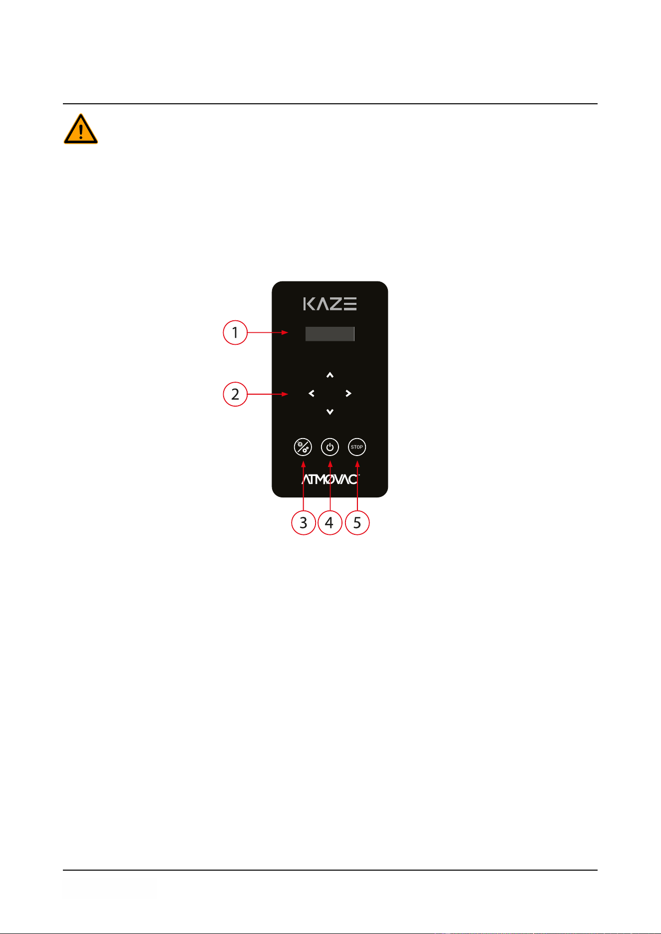
Figure 3: Control Panel
1. Display
The display shows all the available programs and settings. During a program, the display
shows the current program cycle.
2. Cursor keys
These keys are used to operate the display.
3. Pump cleaning program and Settings button
A short press is used to activate the pump cleaning program. Moisture can condensate in the
oil when the pump is running only short cycles or when you are packaging moisture-containing
products. This program removes moisture from the oil of the vacuum pump. See Running the
Pump Cleaning Program on page 39 for instructions.
A long press (3 seconds) is used to activate the settings menu. This menu is only accessible
with the owner login code. Refer to Changing the Machine Settings on page 27.
4. On/Off button
Serves to turn the Kaze on or off.
Operation 20

5. STOP button
This is used to interrupt the entire cycle during a packaging cycle. All functions are skipped
and the cycle is terminated. The STOP button is also used to exit the programming function
and to exit the menu.
6.1.2 Starting the Machine
1. Plug in the machine (see Electrical Installation on page 45).
2. Press the On/Off button on the control panel to enable the operation.
The screen shows the last used program.
When the vacuum pump needs to be cleaned, the machine shows the warning message “pump
cleaning needed” for 5 seconds after power on. Close the machine lid while the message is
showing to immediately run the pump cleaning program. Refer to Running the Pump Cleaning
Program on page 39.
6.1.3 Starting the Packaging Cycle
The machine must be started in accordance with Starting the Machine on page 21 before
starting a packaging cycle.
1. Select the desired program.
Press the
▲▼
button
2. Put the product/products in place.
a. Put the product/products in the vacuum bag.
b. Place the vacuum bag in/on the vacuum chamber. Make sure the opening(s) is/are
correctly placed with regard to the seal position(s).
3. Close the lid.
The packaging cycle will start.
6.1.4 Proceeding to the Next Step in the Cycle
For some products, it may be necessary to proceed to the next step in the packaging cycle before
the vacuum time or the vacuum level has been reached.
When packaging moisture-containing products, such as soups and sauces, it is important
to closely monitor the vacuuming process. The moment bubbles are formed or the product
starts to bubble, you should immediately proceed to the next step in the cycle.
1. Proceed to the next step in the cycle.
Press the
▶
button.
The next step will be started.
6.1.5 Terminating a Program
Programmes such as the packaging program or the pump cleaning program can be terminated at
any time.
Operation 21
1. Terminate the program.
Press the STOP button.
The program will be terminated and the vacuum chamber is decompressed.
6.1.6 Changing the Program Settings (manual)
This section describes the units and limits of the parameters and how parameters can be adjusted.
See Operating Elements on page 20 for an overview of the operating elements.
1. Use the
▲
and
▼
buttons to select the desired program.
2. Use the
►
buttons to scroll to the desired parameter.
The
◄
button can be used to scroll backwards.
The current parameter value is showed on the screen.
3. Use the
▲
and
▼
buttons to adjust the value.
4. Press the
►
button to view the next parameter.
5. Repeat steps 2 - 4 until all parameters are set.
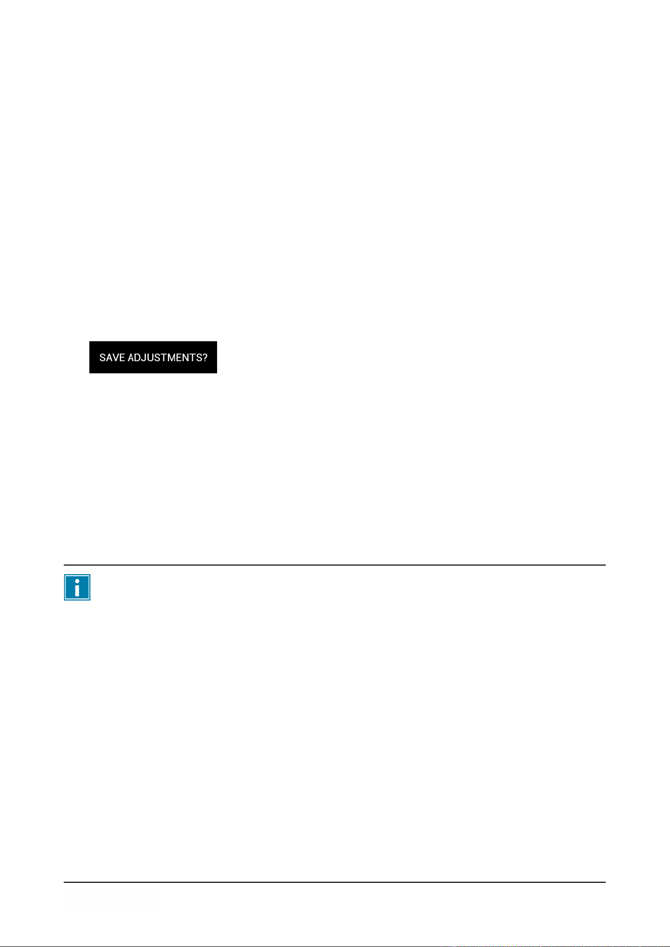
The screen displays “Save adjustments?”.
6. Choose to save or reject the new parameters.
• Press the
►
button to save the new parameters and return to the main menu.
• Press the STOP button to keep the old parameters and return to the main menu.
6.1.7 Changing the Program Settings (automatic)
It is possible to change the program settings while running (and observing) the program. This is
called automatic programming.
See Operating Elements on page 20 for an overview of the operating elements.
Press the STOP button during automatic programming to return to the main menu without
saving the new parameters.
1. Use the
▲
and
▼
buttons to select the desired program.
2. Use the
►
buttons to start changing the program.
The first parameter value is showed on the screen.
3. Put the product/products in place.
a. Put the product/products in the vacuum bag.
b. Place the vacuum bag in/on the vacuum chamber. Make sure the opening(s) is/are
correctly placed with regard to the seal position(s).
4. Close the lid.
The packaging cycle will start.
5. When it is time to proceed to the next step in the cycle, press the
▶
button.
The next step will be started.
Operation 22
The following parameters cannot be set during automatic programming. In these
cases, pressing the
▶
button will have no effect.
• Liquid Control
• Red Meat
• Seal
6. Complete the program.
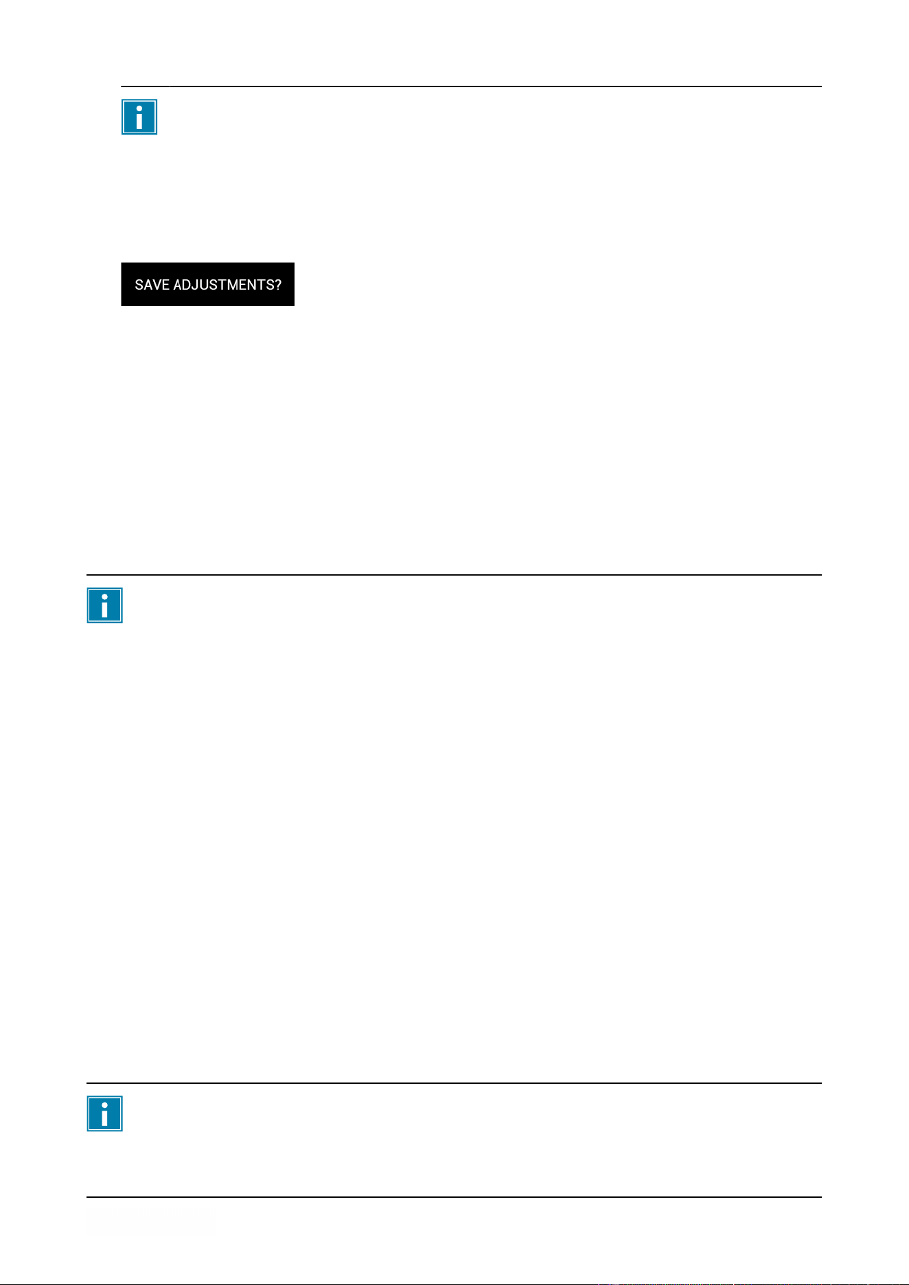
The screen displays “Save adjustments?”.
7. Choose to save or reject the new parameters.
• Press the
►
button to save the new parameters and return to the main menu.
• Press the STOP button to keep the old parameters and return to the main menu.
6.1.8 Program Settings Parameters
6.1.8.1 Vacuum
During the cycle, the air is removed from the chamber until the set percentage or value in mBar or
hPa has been reached.
The set value can only be reached if the product does not start boiling. For more
information, refer to Liquid Control (optional) on page 23.
1. Use the
◄
and
▶
buttons to scroll to the parameter Vacuum.
The screen displays the current vacuum parameter setting.
2. Press the
▲
or
▼
button to adjust the value.
The vacuum parameter can be set from 30 % to 99 %.
3. Press the
▶
to program another parameter or to go to Save settings.
6.1.8.2 Liquid Control (optional)
The boiling point of fluids decreases when the pressure is reduced, see Vapour Pressure Curve of
Water on page 46. As a result, a product may start boiling during the vacuum process. This may
contaminate the machine and reduces the weight and quality of the product to be packaged. If the
Liquid Control option is enabled, the machine will vacuum until the set vacuum is reached. If the
product reaches the boiling point before the set vacuum is reached, the machine will proceed to the
next step of the cycle. The Liquid Control option requires a special sensor, which is not available in
the standard configuration of the machine.
The set vacuum value can only be reached if the product does not start boiling.
Operation 23
1. Use the
◄
and
▶
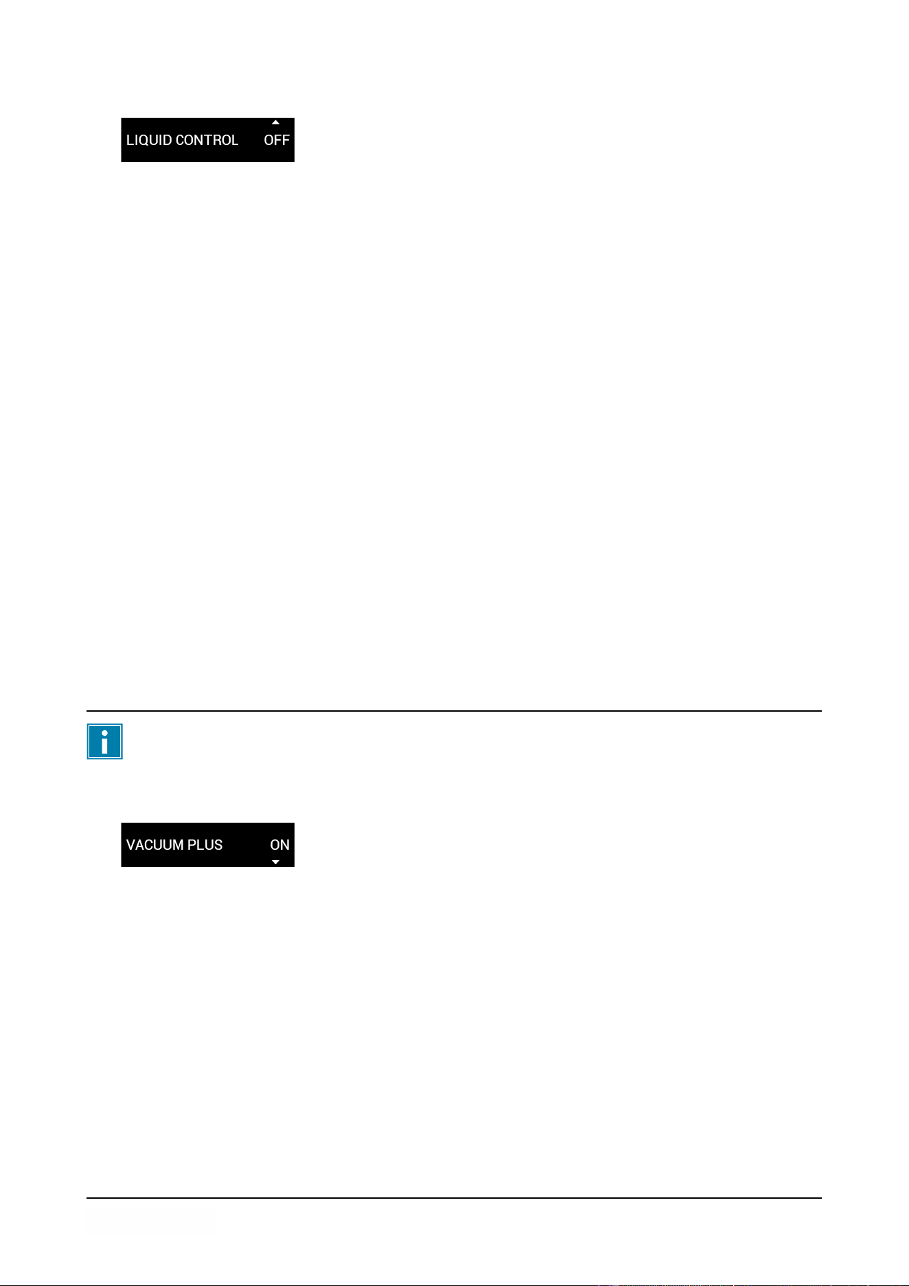
buttons to scroll to the parameter Liquid control.
The screen displays the current liquid control parameter setting.
2. Press the
▲
or
▼
button to adjust the value.
The vacuum parameter can be set On or Off.
3. Press the
▶
to program another parameter or to go to Save settings.
The Liquid Control function prevents excessive fluid from being drawn out of the product. This
means that if the product reaches the boiling point, the machine will proceed to the next step of the
cycle. Depending on the moisture content, the manner in which moisture is bound, the available
surface for evaporation and the temperature, the end vacuum percentage might be limited and
there might be too much residual oxygen content present in the package. If the product/process
requires packaging with a low residual oxygen content, despite the high moisture content, there are
two options:
1. Lower the product temperature. This allows for a deeper vacuum to be reached before the
product reaches the boiling point.
2. Use the Liquid Control+ option.
6.1.8.3 Vacuum+ time (optional)
When air inclusions appear in the product, it may be desirable to prolong the vacuum time after
reaching the maximum vacuum. Because of the evaporation, a minor shock wave may occur,
pushing all remaining air from the bag. This process is meant to let enclosed air escape from the
product. The Vacuum+ time is set in seconds. The best way to determine the right time is trial and
error.
The Vacuum+ option can only be activated if the vacuum value is set to maximum (99 %
or 99.8 % for the ).
1. Use the
◄
and
▶
buttons to scroll to the parameter Vacuum plus.
The screen displays the current vacuum plus parameter setting.
2. Press the
▲
or
▼
button to adjust the value.
The vacuum plus parameter can be set Off or:
• from 0.1 s to 5.0 s (optional Liquid control On);
• from 1 s to 60 s (Liquid control Off or not available).
3. Press the
▶
to program another parameter or to go to Save settings.
6.1.8.4 Seal
This is the time that the sealing wire and/or the cut-off wire are heated. The longer the time, the
more heat is transferred to the bag.
Operation 24
1. Use the
◄
and
▶
buttons to scroll to the parameter Seal.
The screen displays the current seal parameter setting.
2. Press the
▲
or
▼
button to adjust the value.
The vacuum parameter can be set from 0.1 s to 4.0 s.
3. Press the
▶
to program another parameter or to go to Save settings.
6.1.8.5 Red Meat (optional)
The Red Meat option is especially designed for the packaging of fresh meat. Degassing the
product during the vacuum process may result in the formation of air pockets inside the package.
The Red Meat option prevents degassing of the product during and after the sealing phase.
The Red Meat option can be set for each program individually. If the Red Meat option is enabled in
a program, it will not be possible to enable the Soft-air option in that program.
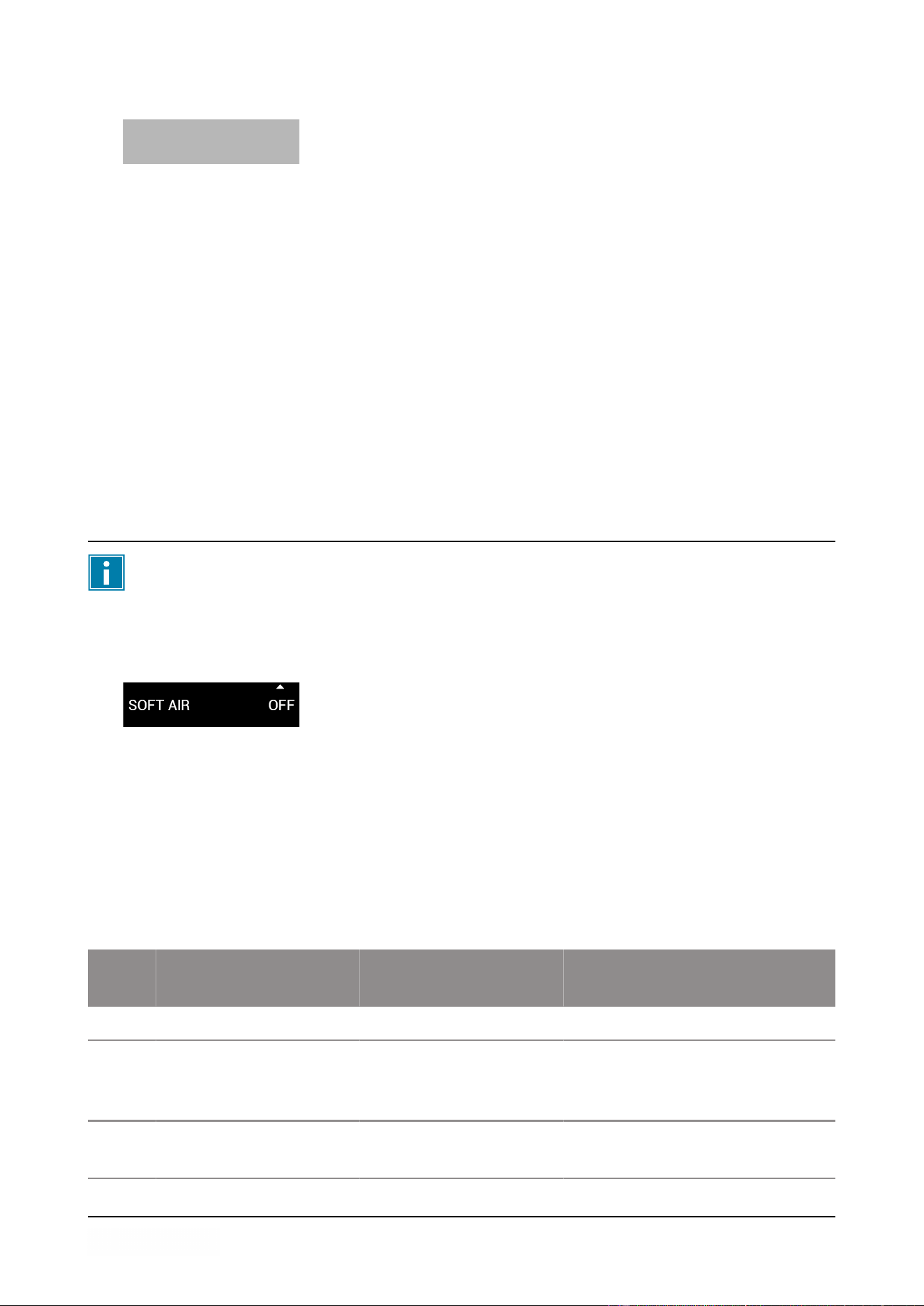
6.1.8.6 Soft Air
This is the time that air is softly released into the chamber after sealing has taken place.
The Soft Air option can not be enabled in a program if the Red Meat option is enabled.
To set the Soft Air function, follow the steps below:
1. Use the
◄
and
▶
buttons to scroll to the parameter Soft Air.
The screen displays the current soft air parameter setting.
2. Press the
▲
or
▼
button to adjust the value.
The soft air parameter can be set Off or on a time from 1 s to 20 s.
3. Press the
▶
to program another parameter or to go to Save settings.
6.1.9 Example programs
The vacuum packaging machine is equipped with sample programs with pre-set parameters. It is
possible to optimize a program for your products by modifying the parameters.
Prog Vacuum Vacuum+ Seal Soft-
Air
Type of
product
1. 99% 5 2.2 s OFF Solid products.
2. 97%
99% (with Liquid Control)
N/A
OFF (with Liquid Control)
2.2 s OFF Liquids or
products con-
taining liquids.
3. 99% OFF 2.2 s 5 s Fragile or sharp
products.
Operation 25

6.1.10 Guidelines for Function Values
For each function, values can be set if you are authorized as an owner. In order to understand the
consequence of the set value, the table below explains the consequences of giving a low or high
value for each function.
For the values in the table below, the following rule of thumb applies to setting a value in mbar.
These values may vary slightly, depending on the humidity.
• 99 % = 10 mbar
• 0% = 1013 mbar
Function Range Conditions
Vacuum 30 – 99% Rule of thumb: the higher the vacuum, the less oxygen re-
mains in the package and the longer the shelf life of the
product. There are exceptions to this rule.
Liquid Control 30 – 99%
If the pressure is reduced, the boiling point of liquids will
be decreased. As a result, a product may start boiling.
This can cause contamination of the machine, and will
reduce the weight and quality of the product to be pack-
aged.
By enabling the Liquid Control function, this special
sensor will detect the evaporation point, and the program
will stop vacuum extracting and proceed to the next step
in the packaging process. The value that can be set is the
maximum achievable vacuum value. Please keep in mind
that this maximum vacuum value can only be achieved as
long as the product does not start boiling.
Vacuum+ 0 – 60 s
or 0.1 – 5.0 s
This is the time the vacuum extracting will continue after
the maximum vacuum has been reached. By adding time,
a vacuum level of 99,8% can be reached. Vacuum+ time
also helps trapped air to escape from the product. Please
note that the vacuum must be set to the maximum.
When liquid control is activated the vacuum + time can
only been set between 0.1 and 5.0 seconds.
Red meat (Op-
tional)
ON- OFF
When packaging pieces of fresh meat, the product can
continue to degas during the sealing phase. Since the
opening of the vacuum bag is already closed, air pockets
may form inside the package after decompressing.
This function can prevent the formation of these air pock-
ets.
Operation 26

Function Range Conditions
Seal time 0.3 – 4.0 s
This is the time that the sealing wires and/or the cut-off
wire are heated. The longer the time, the more heat is
transferred to the bag.
Cleaning of the
pump
15 min. Fixed value.
The vacuum in the chamber must be at least 30% at the moment of sealing.
If the pressure is reduced, the boiling point of liquids will be decreased (see Vapour Pressure
Curve of Water on page 46). As a result, a product may start boiling. This can cause
contamination of the machine, and will reduce the weight and quality of the product to be
packaged.
When packaging moisture-containing products, such as soups and sauces, it is important to
closely monitor the vacuuming process. If bubbles are forming or the product starts to boil, you
should immediately proceed to the next step in the cycle. A higher vacuum can be achieved by
letting products cool down sufficiently prior to starting the vacuuming process.
If the machine is equipped with the Liquid Control option, the control will automatically proceed to
the next step if the product starts boiling.
When packaging moisture-containing products, it is important to run the pump cleaning program
at least once a week. When moisture-containing products are vacuumed on a daily basis, it is
recommended to run the pump cleaning program at the end of every day.
6.1.11 Changing the Machine Settings
This section describes the machine settings that can be changed by the owner.
See Operating Elements on page 20 for an overview of the operating elements.
1. Press and hold the Pump cleaning program and Settings button for 3 seconds.
2. Provide the owner login code.
Use the
◄
and
▶
buttons to select a number and use the
▲
and
▼
buttons to change the
number.
Confirm the code with the
▶
button.
The owner login code is 1324.
3. Use the
▲
and
▼
buttons to select the desired menu.
4. Use the
▲
and
▼
buttons to adjust the value.
• Settings
• Service
Operation 27

• Import & Export
5. Press the
►
button to enter the menu.
6.1.11.1 Settings
In this menu the machine settings can be changed.
• Use the
▲
and
▼
buttons to select the settings sub-menu and use the
►
button to confirm.
∘
Units
∘
Language
∘
Display
∘
Program options
∘
Machine information
• Change the units
a. Use the
▲
and
▼
buttons to select the unit.
∘
%
∘
mbar
∘
hPa
• Change the language
a. Use the
▲
and
▼
buttons to select the language.
∘
English
∘
Español
∘
Nederlands
∘
Français
∘
Deutsch
• Change the display setting
a. Use the
▲
and
▼
buttons to select Display power low and use the
►
button to confirm.
∘
01 minutes
∘
02 minutes
∘
03 minutes
∘
04 minutes
∘
05 minutes
b. Use the
▲
and
▼
buttons to select Display power off and use the
►
button to confirm.
∘
15 minutes
∘
30 minutes
∘
45 minutes
∘
60 minutes
• Switching program options on or off
a. Use the
▲
and
▼
buttons to select External vacuum and use the
►
button to confirm.
∘
On
Operation 28
∘
Off
b. Use the
▲
and
▼
buttons to select Red meat and use the
►
button to confirm.
∘
On
∘
Off
Not all program options are available on all machines.
• Show machine information
The machine information is shown.
∘
SW version
∘
Liquid control (on/off)
∘
Soft air (on/off)
• Use the
▲
and
▼
buttons to select Prog. amount. and use the
►
button to confirm.
∘
3
∘
2
∘
1
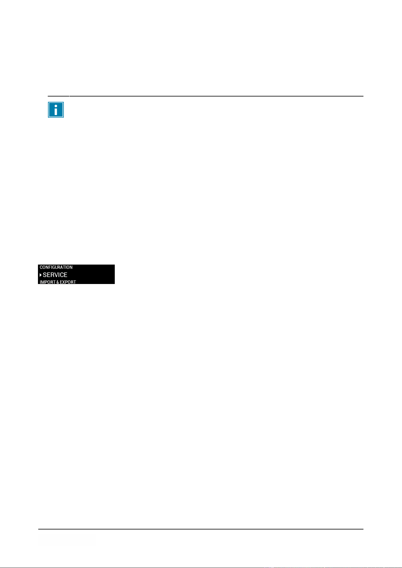
6.1.11.2 Service
In this menu the service warning or the entire machine can be reset.
• Use the
▲
and
▼
buttons to select the service sub-menu and use the
►
button to confirm.
∘
Factory reset
∘
Reset service warning
• Factory reset
a. Use the
▶
to select Factory reset?.
∘
Use the
▶
button to perform the factory reset.
∘
Use the
◄
or STOP button to cancel the factory reset.
• Reset the service warning
a. Use the
▶
button to reset the service warning.
6.1.11.3 Import
This menu is used for software updates. The USB port is located on the right side of the front
panel.
Operation 29

1. USB port
Figure 4: USB port location
• Update
a. Use the
▲
and
▼
buttons to select Software update and use the
►
button to confirm.
6.1.11.4 External Vacuum (optional)
The External Vacuum function allows special food containers to be vacuum extracted outside of the
machine.
Check in advance whether the relevant gastronorm container can withstand and hold a vacuum.
To select the External Vacuum option, follow the steps below.
1. Select the External Vacuum program.
2. Connect the external vacuum hose to the machine by placing the adapter over the suction
inlet (1) in the vacuum chamber.
3. To connect the external vacuum hose to the food container:
a. Connect the external vacuum hose adapter (3) to the valve of the food container.
b. Slide the sliding valve (2) towards the hose (closed position).
Figure 5: External Vacuum Adapter Set
4. Press the
►
button to start the vacuum cycle.
The food container will be vacuum extracted.
5. Slide the sliding valve of the adapter towards the gastronorm container (open position) and
remove the external vacuum hose from the food container.
Operation 30
7 Maintenance
When carrying out maintenance work, always observe the following safety rules.
• Always disconnect the power supply by disconnecting the plug.
• Only trained technicians are authorised to perform the described maintenance activities.
• Test the machine after carrying out maintenance work or repairs to make sure the
machine can be used safely.
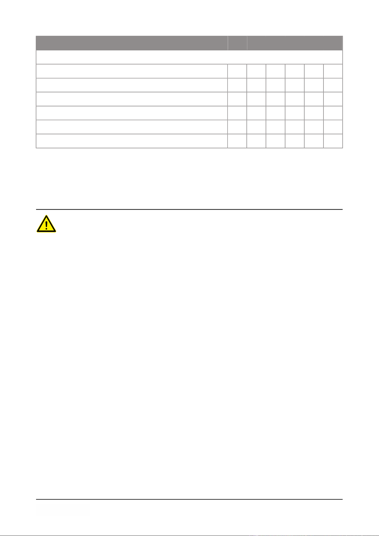
7.1 Maintenance Schedule
The diagram below shows the maintenance activities that must be performed and the interval with
which these activities must be performed.
For specific descriptions for performing maintenance activities, consult the appropriate section.
Activity * 1-D 1-W 1-M 6-M 1-Y 4-Y
Cleaning
Cleaning the machine. X
Inspections
Check the oil level. X
Run the pump cleaning program. X
Inspect the sealing bars. X
Inspect the silicone rubber of the silicone holders. X
Inspect the lid gasket. X
Check the plastic lid for cracks (if applicable). X
Inspect the lid springs. Pay additional attention to damage
and the fastenings of the lid springs.
X
Lubrication
Replace the oil of the vacuum pump. See Technical Data on
page 44 for the type of oil.
X
Maintenance 31
Activity * 1-D 1-W 1-M 6-M 1-Y 4-Y
Replacement
Replace the sealing wires. X
Replace the silicone rubber of the silicone holders. X
Replace the lid gasket. X
Replace the oil exhaust filter. X
Contact your dealer for professional servicing. X
Replace the plastic lid (if applicable). X
* 1-D = Daily, 1-W = Weekly, 1-M = Every month, 6-M = Every 6 months, 1-Y = Annually, 4-Y =
Every 4 years
7.2 Cleaning the Machine
• Never clean the machine using a high pressure cleaner.
• Do not use any aggressive or toxic cleaning agents.
• Do not use any cleaning agents containing solvents.
1. Clean the surfaces with a soft, damp cloth. You can also apply a cleaning agent to the
machine and wash it with clean water.
7.3 Replacing the Sealing Wire
Depending on the specifications of your machine, you can have one of the following (combinations
of) sealing wires:
• Wide seal: one wide sealing wire
• Double seal: two sealing wires
• Trenn seal: one sealing wire and one cutting wire
The process of replacing the sealing wires is the same for all types.
Replace the sealing wires if the wire and/or the Teflon tape are damaged, or as specified in
Maintenance Schedule on page 31.
Maintenance 32

Figure 6: Removing the Sealing Bar
1. Remove the sealing bar by lifting it from the cylinders. See Figure 6: Removing the Sealing
Bar on page 33.
Figure 7: Replacing the Sealing Wire
2. Remove the Teflon tape (1) that protects the sealing wire.
3. Remove the screws (2) at the bottom of the sealing bar and remove the sealing wires (3).
4. Replace the Teflon tape on the sealing bar.
a. Pull the Teflon tape from the top of the sealing bar (4).
b. Clean the sealing bar with a dust-free cloth.
c. Apply a new piece of Teflon tape of the same length on the sealing bar.
5. Replace the sealing wires.
a. Cut a new piece of sealing wire or cutting wire at the length of the sealing bar plus
approximately 5.9 in (15 cm).
b. First place the wire on one side of the sealing bar by tightening the screws (2).
Maintenance 33

c. Place the other end of the wire in its location and tension it with pliers. Now fasten it by
tightening the screws.
d. Cut both ends of the wire.
6. Replace the Teflon tape on the sealing wire.
a. Cut a piece of Teflon tape at the length of the sealing bar plus approximately 2.0 in
(5 cm).
b. Attach the tape over the sealing wires on the sealing bar evenly and without folds.
c. Cut the tape.
7. Place the sealing bar back in its position.
7.4 Replacing the Silicone Rubber of the Silicone Holders
To ensure a seal of good quality, the silicone rubber may not be damaged and the surface must be
smooth. Mechanical contact or burning by the sealing wire may damage the rubber.
Replace the silicone rubber if damaged or as specified in Maintenance Schedule on page 31.
Figure 8: Replacing the Silicone Rubber of the Silicone Holders
1. Pull the old silicone rubber from the holder, see Figure 8: Replacing the Silicone Rubber of the
Silicone Holders on page 34.
2. Cut a new piece of silicone rubber. Make sure it is the same length as the holder.
If the rubber is too short or too long, this may cause problems with the seal of the
bag.
3. Install the new piece of silicone rubber by pressing it into the recess of the silicone holder.
Ensure that the silicone rubber is fully and uniformly placed in the recess. It is also important
that the surface of the silicone rubber is smooth after it is in place, and that it shows no signs
of stress.
Maintenance 34
7.5 Replacing the Lid Gasket
The lid gasket ensures the vacuum chamber is fully closed during the machine cycle. This is
essential to reach the maximum vacuum level. Due to extreme pressure differences, the gasket
wears and should therefore be replaced regularly.
Replace the lid gasket if damaged or as specified in Maintenance Schedule on page 31.
Figure 9: Replacing the Lid Gasket
1. Pull the old gasket loose to remove it.
2. Cut a new piece of rubber.
Preferably cut the new piece of rubber slightly longer than the old piece.
The edges must be cut straight.
If the lid gasket is too short or too long, this may cause problems when closing the lid
or it may cause leakage.
3. Install the new gasket by pressing it into the gasket slot. The lip of the gasket must face
downwards and outwards.
The gasket should be placed in the slot evenly and without any tension. The edges must be
placed closely together to prevent leakage.
7.6 Inspecting the Lid Springs
1. Check the fastenings of the lid springs for wear, corrosion and damage.
2. Check the lid springs for wear and damage.
In the case of leakage, please contact your service dealer.
Maintenance 35

7.7 Vacuum Pump maintenance
The vacuum pump creates the vacuum. Regular maintenance of the pump is very important.
7.7.1 Overview
Depending of the configuration the machine is equipped with one of the following pumps:
7.7.1.1 Pump 10 m
3
/h (338 cf/h)
Figure 10: Overview of the Pump
1. Vacuum pump - Creates the vacuum for the process.
2. Oil exhaust filter - Filters the air by capturing oil vapours.
3. Oil sight glass - Indicates the maximum and minimum oil levels of the vacuum pump.
4. Oil drain plug - Removing the oil drain plug allows the oil to be drained.
5. Oil filler plug - Removing the oil filler plug allows the oil to be refilled.
Maintenance 36

7.7.1.2 Pump 19 - 25 m
3
/h (678 - 889 cf/h)
Figure 11: Overview of the Pump
1. Vacuum pump - Creates the vacuum for the process.
2. Oil exhaust filter - Filters the air by capturing oil vapours.
3. Oil sight glass - Indicates the maximum and minimum oil levels of the vacuum pump.
4. Oil drain plug - Removing the oil drain plug allows the oil to be drained.
5. Oil filler plug - Removing the oil filler plug allows the oil to be refilled.
7.7.2 Service hatch
A maintenance hatch can be found on the side of the machine. After loosening two bolts, it
can then be removed with a tilting movement so that the drain openings of the pump are freely
accessible.
Figure 12: Service hatch
7.7.3 Removing Oil, Refilling Oil
This section describes how to remove oil from the pump and how to refill the oil.
Maintenance 37

See Overview on page 36 for the pump fitted in the machine and an overview of the parts.
If the machine remains unused for a prolonged period of time, the oil must be removed from the
pump. This is necessary because moisture and dirt in the oil may affect the pump, causing the
pump to jam at the next use.
The oil in the vacuum pump may be hot. Avoid contact with hot oil when removing the oil.
Follow the steps below to remove the oil from the pump:
1. Place a drip pan under the oil drain plug.
2. Remove the oil drain plug.
The oil will drain from the pump.
3. Replace the oil drain plug.
Follow the steps below to add oil to the pump. You can follow these steps after all oil has been
removed, but also to refill oil.
4. Remove the oil filler plug.
5. Add oil until the oil level is between the minimum and maximum levels of the oil sight glass.
6. Replace the oil filler plug.
7.7.4 Replacing the Oil Exhaust Filter
The oil exhaust filter prevents oil vapours from being emitted from the vacuum pump with the
exhaust air. If the filter becomes saturated, the maximum vacuum level can no longer be reached.
Replace the filter in case of vacuum problems or as specified in Maintenance Schedule on page
31.
7.7.4.1 Pump 10 m
3
/h (338 cf/h)
Figure 13: Replacing the Oil Exhaust Filter
Maintenance 38

Follow the steps below to remove the old oil exhaust filter:
1. Remove the filter cover (3) of the vacuum pump (1) and put it aside.
2. Remove the oil exhaust filter (2) from the vacuum pump.
Follow the steps below to install a new oil exhaust filter:
3. Turn the new filter into the vacuum pump.
Make sure the O-ring is properly placed on the filter inlet.
4. Mount the filter cover placed aside.
7.7.4.2 Pump 19 - 25 m
3
/h (678 - 889 cf/h)
Figure 14: Replacing the Oil Exhaust Filter
Follow the steps below to remove the old oil exhaust filter:
1. Remove the filter cover (4) of the vacuum pump (1) and put it aside.
2. Remove the leaf spring (3) and put it aside.
3. Remove the old filter (2).
Follow the steps below to install a new oil exhaust filter:
4. Insert the new filter into the vacuum pump.
Make sure the O-ring is properly placed on the filter inlet.
5. Mount the leaf spring placed aside.
6. Mount the filter cover placed aside.
7.7.5 Running the Pump Cleaning Program
The pump cleaning program runs the vacuum pump for 15 minutes. During the program, the pump
and the oil reach the operating temperature. Moisture in the pump is absorbed by the oil. The high
temperature causes any moisture in the pump to evaporate, and minimises the risk of corrosion.
Maintenance 39

It is advisable to run the program before using the machine for the first time, after the machine has
been stationary for a lengthy period of time, and especially prior to changing oil.
Run the pump cleaning program every week. If you package moisture-containing products, such as
soups and sauces, the pump cleaning program should be run every day.
1. Select the pump cleaning program.
Press the Pump cleaning program and Settings button.
2. Close the lid to start the pump cleaning program.
The pump cleaning program will run for 15 minutes up to 100%.
Maintenance 40

8 Troubleshooting and Error Codes
The tables below show the possible malfunctions and the corresponding causes as well as the
steps to be taken.
Malfunction Activity More information
Control panel does not illumin-
ate.
• Connect the machine to the
power supply.
• Check the circuit breaker on
the back of the machine.
Connecting the Machine on
page 18
Electrical Installation on page
45
The control panel is on, but
there is no activity after closing
the lid.
• Check or adjust the switch of
the lid.
Contact your supplier.
Insufficient end vacuum. • Check the vacuum settings
of the program and adjust
them.
• Make sure that the extrac-
tion opening is not covered.
• Check the oil level in the
pump.
• Check/replace the oil ex-
haust filter.
• Check/replace the lid gas-
ket.
Operation on page 20.
Vacuum Pump maintenance on
page 36.
Replacing the Oil Exhaust Filter
on page 38.
Replacing the Lid Gasket on
page 35.
Vacuum process is slow. • Make sure that the extrac-
tion opening is not covered.
• Check the oil level in the
pump.
• Check/replace the oil ex-
haust filter.
Replacing the Oil Exhaust Filter
on page 38.
Troubleshooting and Error Codes 41

Malfunction Activity More information
Vacuum bag is not sealed cor-
rectly.
• Check the seal settings
of the program and adjust
them.
• Check/replace the Teflon
tape and the sealing wires.
• Check/replace the silicone
rubber of the silicone hold-
ers.
• Check the inside of the va-
cuum for contamination and
clean it.
Operation on page 20.
Replacing the Sealing Wire on
page 32.
Replacing the Silicone Rubber
of the Silicone Holders on page
34.
Error messages
Malfunction Activity More information
Cycle aborted!
• Check whether the lid is
open.
• Close the lid.
Do not open the lid before the
program is finished.
Pressure sensor failure!
• Check whether the sensor is
connected.
In case the malfunction reoc-
curs, contact your supplier.
Pump cleaning needed!
• Run the pump cleaning pro-
gram.
Start the pump cleaning pro-
gram by closing the lid. The
program takes 15 minutes.
Oil change needed!
• A service check is needed. Activity: A service check is
needed
For more information: contact
your supplier
Troubleshooting and Error Codes 42

9 Disposal
Do not dispose of oil and components as household waste. When repla-
cing oil or components at the end of the service life, ensure that all ma-
terials are collected and disposed or reused in a legal and environment-
ally sound manner.
Disposal 43

10 Appendices
10.1 Technical Data
10.1.1 Kaze series
Kaze 14 16 16XL
General
Ambient temperature during operation 41 to 86°F 41 to 86°F 41 to 86°F
Machine working conditions: relative
humidity (non-condensing)
10-90% 10-90% 10-90%
Sound emission < 70 dB(A) < 70 dB(A) < 70 dB(A)
Maximum daily production 5 hrs/day 5 hrs/day 5 hrs/day
Dimensions of the machine
Width 16.8 in 19.3 in 19.3 in
Length 21.4 in 20.6 in 24.1 in
Height 21.8 in 18.3 in 18.5 in
Weight 80 lbs 126 lbs 150 lbs
Maximum product height 5.9 in 7.0 in 7.0 in
Electrical connection
Supply voltage * * *
Connected load * * *
Vacuum pump
Capacity 8 m
3
/h - 283 cfh 16 m
3
/h - 565 cfh 16 m
3
/h - 565 cfh
Oil 0.25 litre 0.3 litre 0.3 litre
Type of synthetic oil Foodmax Air 32 Foodmax Air 32 Foodmax Air 32
Ambient temperature synthetic oil 14 to 104°F 14 to 104°F 14 to 104°F
*See machine plate.
**For different temperatures, please contact your dealer.
Appendices 44

10.2 Electrical Installation
The electrical installation provides power for the vacuum pump, the seal system and the operation
of the machine.
See the electrical diagram for the further structure and operation of the electrical installation.
Please contact your supplier for the electrical diagram.
Only a technical expert may perform work on the electrical installation.
The machine consists of the following electrical components:
Figure 15: Overview of the Electrical Installation
1. Power cable and circuit breaker
This serves to connect the machine to the power supply.
The circuit breaker protects against overload or short circuit.
2. Control panel
This serves to operate the control functions. Your machine has the following control option:
• Kaze Control System on page 20
Appendices 45

10.3 Vapour Pressure Curve of Water
Figure 16: Vapour Pressure Curve of Water
Appendices 46
10.4 Logbook
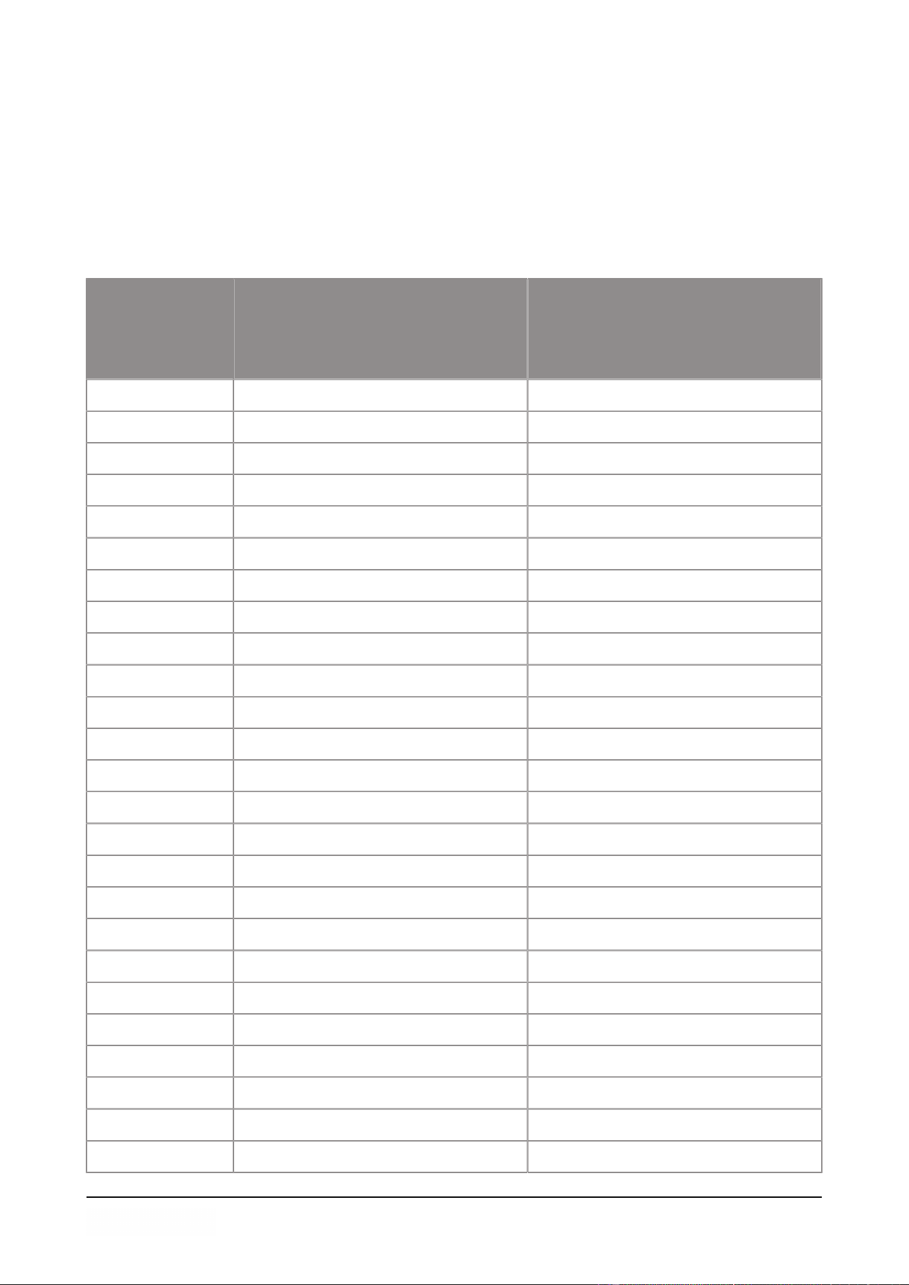
This logbook must include:
• Annual maintenance work
• Major replacements and emergencies
• Modifications
• Tests of the emergency stop buttons and safety devices
Date:
Performed by:
(authority, technician)
Description:
(nature of the activities, which
parts have been replaced)
Appendices 47
Date:
Performed by:
(authority, technician)
Description:
(nature of the activities, which
parts have been replaced)
Appendices 48

49

50

51

Eurodib Eurodib Corp
120 de la Barre 334 Cornelia St #272
J4B 2X7 Boucherville (Quebec) NY 12901 Plattsburgh
+1 (888) 956-6866 +1 (888) 956-6866
https://www.eurodib.com https://www.eurodib.com
info@eurodib.com info@eurodib.com