
R900A Series
Wireless Sensor
R900A Series User Manual
Copyright©Netvox Technology Co., Ltd.
This document contains proprietary technical information which is the property of NETVOX Technology. It shall be maintained in
strict confidence and shall not be disclosed to other parties, in whole or in part, without written permission of NETVOX Technology.
The specifications are subject to change without prior notice.

Contents
1. Introduction .................................................................................................................................1
2. Appearance ..................................................................................................................................2
3. Features ....................................................................................................................................... 4
4. Setup Instructions ....................................................................................................................... 5
5. Data Report ................................................................................................................................. 7
5.1 Example of ReportDataCmd ............................................................................................... 7
5.2 Example of ConfigureCmd ..................................................................................................9
5.3 Example of SetSensorAlarmThresholdCmd .....................................................................12
5.4 Example of GlobalCalibrateCmd ...................................................................................... 14
5.5 Example of NetvoxLoRaWANRejoin...............................................................................15
5.6 Example for MinTime/MaxTime logic ............................................................................. 17
6. Read R900 Data on NFC App .................................................................................................. 19
7. Installation .................................................................................................................................24
8. Battery Passivation ................................................................................................................... 28
9. Important Maintenance Instructions ........................................................................................ 28

1
1. Introduction
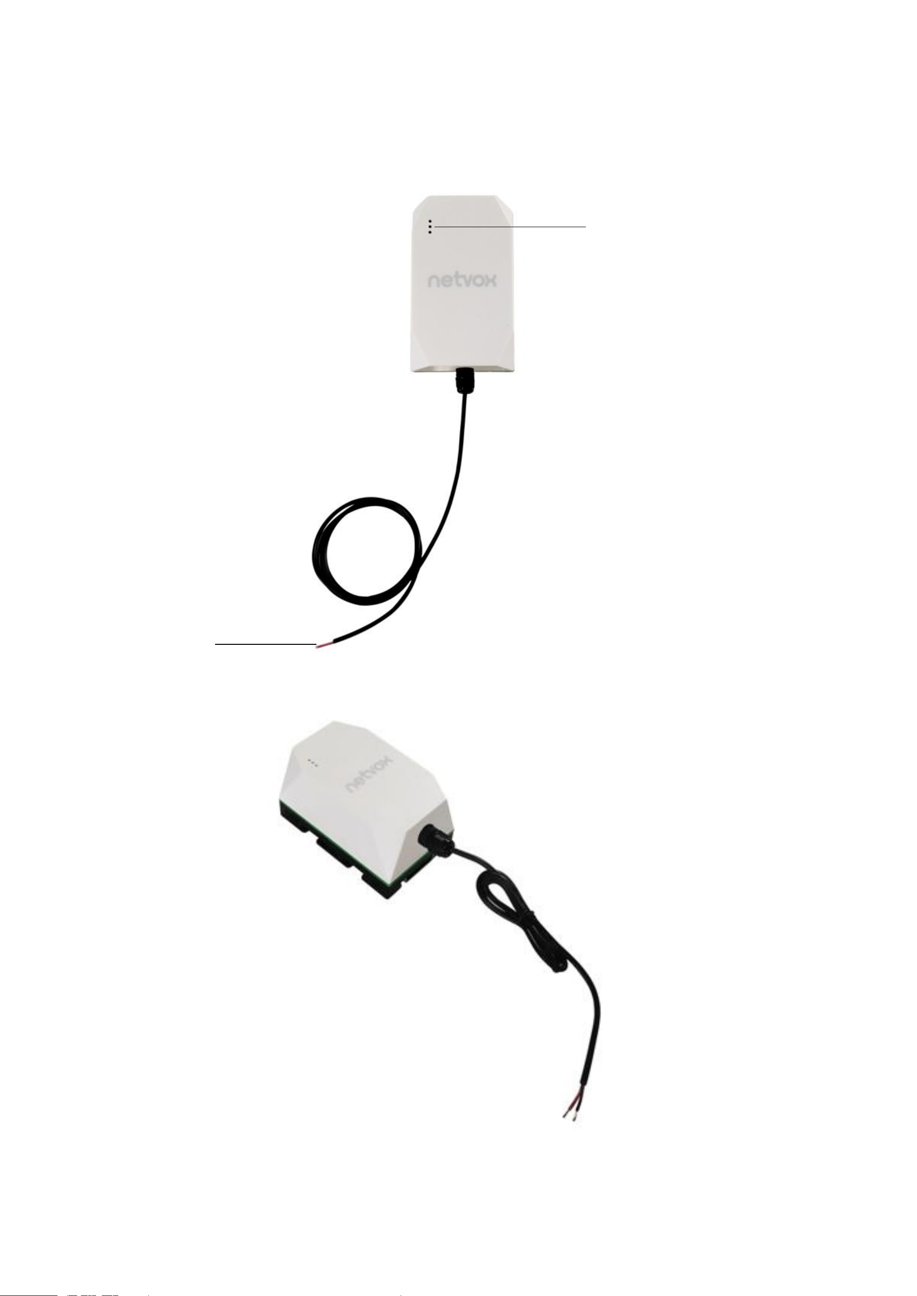
The R900A series devices are Netvox-manufactured LoRaWAN-compliant Class A/Class C multi-functional devices that support
the detection of temperature, humidity, light, water leak, tile angle, etc. The devices integrate built-in vibration sensors for tamper
detection and support one/two output/input signals, enabling threshold-alarm-triggered control of third-party devices.
Additionally, these devices can monitor environmental parameters including temperature, humidity, and ambient light intensity,
supporting both DC power supply and battery operation.
LoRa Wireless Technology
LoRa is a wireless communication technology famous for its long-distance transmission and low power consumption. Compared
with other communication methods, LoRa spread spectrum modulation technique greatly extends the communication distance. It
can be widely used in any case that requires long-distance and low-data wireless communications. For example, automatic meter
reading, building automation equipment, wireless security systems, and industrial monitoring. It has features like small size, low
power consumption, long transmission distance, strong anti-interference ability, and so on.
LoRaWAN
LoRaWAN uses LoRa technology to define end-to-end standard specifications to ensure interoperability between devices and
gateways from different manufacturers.
2
2. Appearance
R900A01O1 for example:
Digital Output
Red (+): 3.3V White (-)
Temperature and Humidity Sensor

3
Top
Bottom
Left Side
Back
NFC
Magnetic
switch

4
3. Features
Powered by 2* 3.6V ER14505/ER18505 batteries or DC
Support magnetic switch to turn on/off and factory reset device
Up to 7 installation methods for different kinds of scenarios
Output/input digital signal based on the threshold of temperature and humidity
Report when device disconnects from the network
Support NFC. Configure and upgrade firmware on Netvox NFC app
Store up to 10000 data
LoRaWAN
TM
Class A compatible
Frequency hopping spread spectrum
Configuration parameters can be configured through third-party software platforms, data can be read, and alarms can be set
via SMS text and email (optional)
Applicable to the third-party platforms: Actility/ThingPark, TTN, MyDevices/Cayenne
Low power consumption and longer battery life
Note: Battery life is determined by the sensor reporting frequency and other variables, please visit
http://www.netvox.com.tw/electric/electric_calc.html for battery life and calculation.
5
4. Setup Instructions
On / Off
Power on
Insert 2* ER18505 batteries or connect a DC adapter.
Power off
Remove the batteries / DC adapter.
Function key
Turn on
Press and hold the function key for 3 seconds until the green indicator flashes once.
Turn off
Step 1. Press and hold the function key for 5 seconds until the green indicator flashes once.
Step 2. Release the function key and short press it in 5 seconds.
Step 3. The green indicator flashes 5 times. R900 turns off.
Factory reset
Step 1. Press and hold the function key for 10 seconds. The green indicator flashes once
every 5 seconds.
Step 2. Release the function key and short press it in 5 seconds.
Step 3. The green indicator flashes 20 times. R900 is factory reset and off.
Magnetic switch
Turn on
Hold a magnet near R900 for 3 seconds until the green indicator flashes once.
Turn off
Step 1. Hold a magnet close to R900 for 5 seconds. The green indicator flashes once.
Step 2. Remove the magnet and get close to R900 in 5 seconds.
Step 3. The green indicator flashes 5 times. R900 turns off.
Factory reset
Step 1. Hold a magnet close to R900 for 10 seconds. The green indicator flashes once
every 5 seconds.
Step 2. Remove the magnet and get close to R900 in 5 seconds.
Step 3. The green indicator flashes 20 times. R900 is factory reset and off.
Note:
a. Remove and insert the battery; the device is off by default.
b. 5 seconds after powering on, the device will be in engineering test mode.
c. The on/off interval should be about 10 seconds to avoid the interference of capacitor inductance and other energy storage components.
d. When the batteries are removed without turning off the device, it can still operate for a while until the power supported by the
supercapacitor runs out.
6
Join a Network
First time joining the network
Turn on the device to search the network.
The green indicator stays on for 5 seconds: Success
The green indicator remains off: Fail
Had joined the network before
(Device is not factory reset.)
Turn on the device to search the network.
The green indicator stays on for 5 seconds: Success
The green indicator remains off: Fail
Fail to join the network
Please check the device verification information on the gateway or consult your platform
server provider.
Function key
Short press
Device is in the network
The green indicator flashes once. 6 seconds after sampling is completed, the device reports
a data packet.
Device is not in the network
The green indicator remains off.
Note: The function key does not work during sampling.
Magnetic switch
Move magnet close to the switch
and remove it
Device is in the network
The green indicator flashes once. After sampling is completed, the device reports a data
packet.
Device is not in the network
The green indicator remains off.
Sleep Mode
The device is on
and in the network.
Sleeping period: Min Interval.
When the reportchange exceeds the setting value or the state changes: send a data
report based on the Min Interval.
The device is on
but not in the network.
(1) Please turn off the device and remove the batteries to save power.
(2) Please check the device verification information on the gateway or consult your
platform server provider.
Low Voltage Alarm
Low voltage
3.2V
Note: To ensure the accuracy of data, please change the battery when it drops to low voltage.
7
5. Data Report
35 seconds after the device is powered on, it will send a version packet and data including battery power, temperature, and
humidity.
Default setting:
Min Interval = 0x0384 (900s)
Max Interval = 0x0384 (900s) // should not be less than 30 seconds
TemperatureChange = 0x0064 (1°C)
HumidityChange= 0x0064 (1%)
Note: a. If no configuration is done, the device sends data based on the default settings.
b. Please refer to Netvox LoRaWAN Application Command document and Netvox Lora Command Resolver
http://www.netvox.com.cn:8888/cmddoc to resolve uplink data.
Data report configuration and sending period are as follows:
Min Interval
(unit: second)
Max Interval
(unit: second)
Reportable Change
Current Change ≥
Reportable Change
Current Change<
Reportable Change
Any number between
30 to 65535
Any number between
Min time to 65535
Cannot be 0
Report
per Min Interval
Report
per Max Interval
5.1 Example of ReportDataCmd
FPort: 0x16
Bytes
1
2
1
Var (length based on the payload)
Version
DeviceType
ReportType
NetvoxPayLoadData
Version – 1 bytes – 0x03——the Version of NetvoxLoRaWAN Application Command Version
DeviceType – 2 bytes – Device Type of Device
The devicetype is listed in Netvox LoRaWAN Application Devicetype V3.0.doc
ReportType – 1 byte –the presentation of the NetvoxPayLoadData, according to the devicetype
NetvoxPayLoadData – Var bytes (length based on the payload)
Tips
1. Battery Voltage
The voltage value is bit 0 – bit 6, bit 7=0 is normal voltage, and bit 7=1 is low voltage.
Battery=0xA0, binary= 1010 0000, if bit 7= 1, it means low voltage.
The actual voltage is 0010 0000 = 0x20 = 32, 32*0.1v =3.2v.
2. Version Packet
When Report Type = 0x00 is the version packet, such as 030111000A0120250424, the firmware version is 2025.04.24.
3. Data Packet
When Report Type=0x01 is the data packet.
4. Signed Value
When the temperature is negative, 2's complement should be calculated.

8
Device
Device
Type
Report
Type
NetvoxPayLoadData
R900A01O1
0x0111
0x01
Battery
(1 Byte,
unit: 0.1V)
Temperature
(Signed 2 Bytes,
unit: 0.01°C)
Humidity
(2 Bytes,
unit: 0.01%)
ThresholdAlarm
(1 Byte)
Bit0_LowTemperatureAlarm,
Bit1_HighTemperatureAlarm,
Bit2_LowHumidityAlarm,
Bit3_HighHumidityAlarm,
Bit4-7: Reserved
ShockTamperAlarm
(1 Byte)
0x00_NoAlarm,
0x01_Alarm
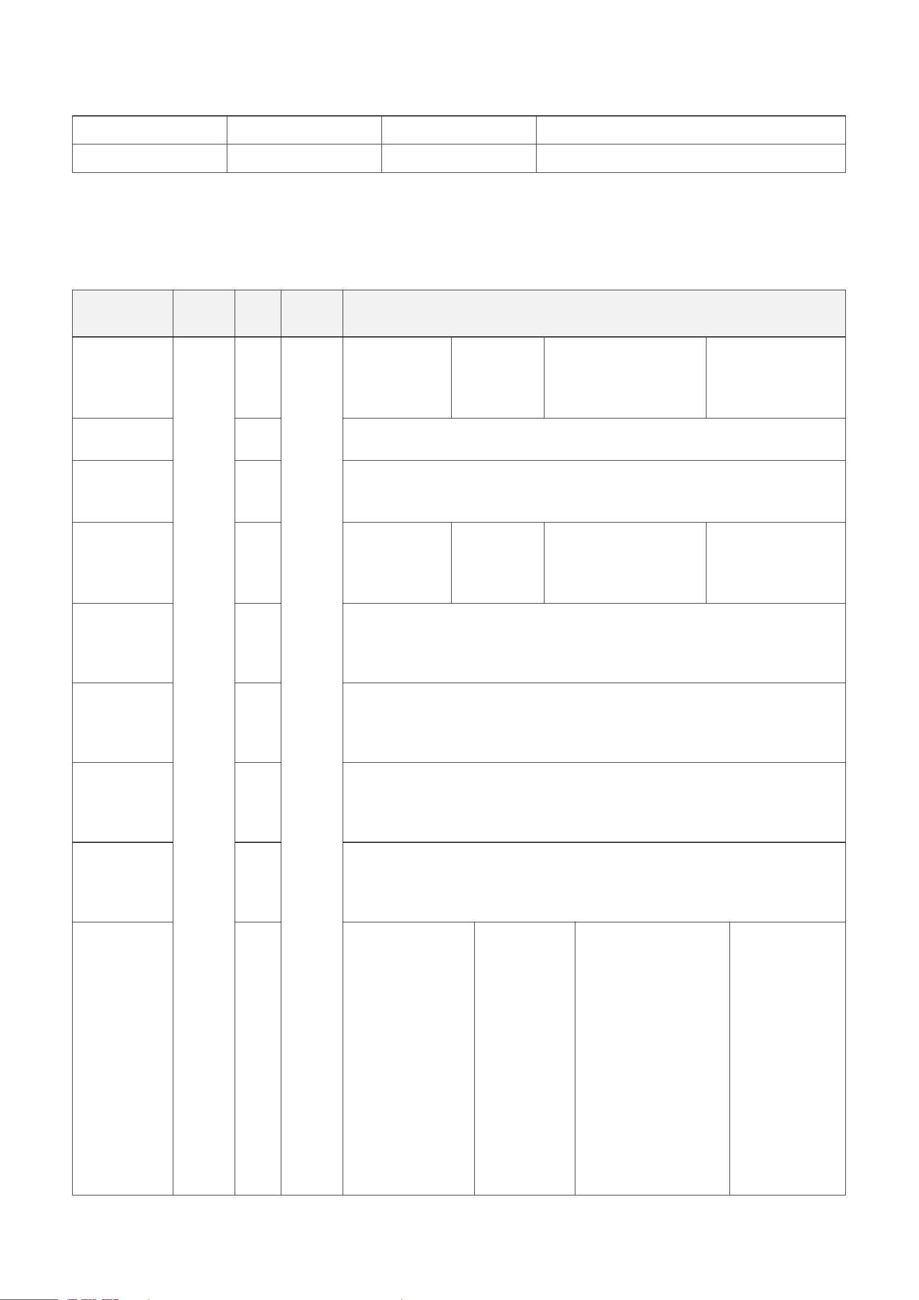
Example of Uplink: 03011101240DAC19640000
1
st
Byte (03): Version
2
nd
3
rd
Byte (0111): DeviceType- R900A01O1
4
th
(01): ReportType
5
th
Byte (24): Battery-3.6V 24 (Hex) = 36 (Dec), 36* 0.1v = 3.6V
6
th
– 7
th
Byte (0DAC): Temperature-35°C 0DAC (Hex) = 3500 (Dec), 3500* 0.01°C = 35°C
8
th
–9
th
Byte (1964): Humidity-65% 1964 (Hex) = 6500 (Dec), 6500* 0.01°% = 65%
10
th
Byte (00): ThresholdAlarm-no alarm
11
th
Byte (00): ShockTamperAlarm-no alarm
9
5.2 Example of ConfigureCmd
FPort: 0x17
Bytes
1
2
Var (length based on the payload)
CmdID
DeviceType
NetvoxPayLoadData
CmdID – 1 byte
DeviceType – 2 bytes – Device Type of Device
The devicetype is listed in Netvox LoRaWAN Application Devicetype3.0.doc
NetvoxPayLoadData – Var bytes (length based on the payload)
Description
Device
Cmd
ID
Device
Type
NetvoxPayLoadData
ConfigReport
Req
R900A
01O1
0x01
0x0111
MinTime
(2 Bytes,
unit: s)
MaxTime
(2 Bytes,
unit: s)
TemperatureChange
(2 Bytes,
unit: 0.01°C)
HumidityChange
(2 Bytes,
unit: 0.01%)
ConfigReport
Rsp
0x81
Status (0x00_success)
ReadConfigR
eportReq
0x02
ReadConfigR
eportRsp
0x82
MinTime
(2 Bytes,
unit: s)
MaxTime
(2 Bytes,
unit: s)
TemperatureChange
(2 Bytes,
unit: 0.01°C)
HumidityChange
(2 Bytes,
unit: 0.01%)
SetShockSens
orSensitivityR
eq
0x03
ShockSensorSensitivity (1 Byte)
SetShockSens
orSensitivityR
sp
0x83
Status (0x00_success)
GetShockSen
sorSensitivity
Req
0x04
GetShockSen
sorSensitivity
Rsp
0x84
ShockSensorSensitivity (1 Byte)
ConfigDigital
OutPutReq
0x05
DigitalOutPutType
(1 Byte)
0x00_NormallyLow
Level
0x01_NormallyHigh
Level
OutPulseTime
(1 Byte,
unit: s)
BindAlarmSource
(1 Byte)
Bit0_LowTemperature
Alarm
Bit1_HighTemperature
Alarm
Bit2_LowHumidityAla
rm
Bit3_HighHumidityAla
rm
Bit4-7: Reserved
Channel
(1 Byte)
0x00_Channel1
0x01_Channle2

10
ConfigDigital
OutPutRsp
0x85
Status (0x00_success)
Read
ConfigDigital
OutPutReq
0x06
Channel (1Byte)
0x00_Channel1
0x01_Channle2
Read
ConfigDigital
OutPutRsp
0x86
DigitalOutPutType
(1 Byte)
0x00_NormallyLow
Level
0x01_NormallyHigh
Level
OutPulseTime
(1 Byte,
unit: s)
BindAlarmSource
(1 Byte)
Bit0_LowTemperature
Alarm
Bit1_HighTemperature
Alarm
Bit2_LowHumidityAla
rm,
Bit3_HighHumidityAla
rm,
Bit4-7: Reserved
Channel
(1 Byte)
0x00_Channel1
0x01_Channle2
TriggerDigital
OutPutReq
0x07
OutPulseTime (1 Byte, unit: s)
Channel (1Byte)
0x00_Channel1
0x01_Channle2
TriggerDigital
OutPutRsp
0x87
Status (0x00_success)
(1) Configure device parameters
MinTime = 0x003C (60s), MaxTime = 0x003C (60s),
TemperatureChange = 0x012C (3°C), HumidityChange = 0x01F4 (5%)
Downlink: 010111003C003C012C01F4
Response: 81011100 (configuration success)
81011101 (configuration fail)
Read device parameters
Downlink: 020111
Response: 820111003C003C012C01F4
(2) Configure ShockSensorSensitivity = 0x14 (20)
Downlink: 03011114
Response: 83011100 (configuration success)
83011101 (configuration fail)
Note: ShockSensorSensitivity range = 0x01 to 0x14
0xFF (disables vibration sensor)
Read ShockSensorSensitivity
Downlink: 040111
Response: 84011114 (device’s current parameters)

11
(3) Configure DigitalOutPutType = 0x00 (NormallyLowLevel),
OutPulseTime = 0xFF (disable pulse duration),
BindAlarmSource = 0x01 = 0000 0001 (BIN) Bit0_LowTemperatureAlarm = 1
(when LowTemperatureAlarm is triggered, DO outputs signals)
Channel = 0x00
_Channel1
Downlink: 05011100FF0100
Response: 85011100 (configuration success)
85011101 (configuration fail)
Read DO parameters
Downlink: 06011100
Response: 86011100FF0100
Configure OutPulseTime = 0x03 (3 seconds)
Downlink: 0701110300
Response: 87011100 (configuration success)
87011101 (configuration fail)

12
5.3 Example of SetSensorAlarmThresholdCmd
FPort: 0x10
CmdDescriptor
CmdID
(1 Byte)
Payload (10 Bytes)
SetSensorAlarm
ThresholdReq
0x01
Channel
(1 Byte)
0x00_Channel1,
0x01_Chanel2,
0x02_Channel3, etc.
SensorType
(1 Byte)
0x00_Disable ALL
0x01_Temperature
0x02_Humidity
SensorHighThreshold
(4 Bytes)
unit:
Temperature – 0.01°C
Humidity – 0.01%
SensorLowThreshold
(4 Bytes)
unit:
Temperature – 0.01°C
Humidity – 0.01%
SetSensorAlarm
ThresholdRsp
0x81
Status (0x00_success)
Reserved (9 Bytes, Fixed 0x00)
GetSensorAlarm
ThresholdReq
0x02
Channel
(1 Byte)
0x00_Channel1,
0x01_Chanel2,
0x02_Channel3, etc.
SensorType
(1 Byte)
0x00_Disable ALL
0x01_Temperature
0x02_Humidity
Reserved (8 Bytes, Fixed 0x00)
GetSensorAlarm
ThresholdRsp
0x82
Channel
(1Byte)
0x00_Channel1,
0x01_Chanel2,
0x02_Channel3, etc.
SensorType
(1 Byte)
0x00_Disable ALL
0x01_Temperature
0x02_Humidity
SensorHighThreshold
(4 Bytes)
unit:
Temperature – 0.01°C
Humidity – 0.01%
SensorLowThreshold
(4 Bytes)
unit:
Temperature – 0.01°C
Humidity – 0.01%
Note:
a. Temperature Channel: 0x00; SensorType: 0x01
Humidity Channel: 0x00; SensorType: 0x02
b. Set SensorHigh/LowThreshold as 0xFFFFFFFF to disable threshold.
c. The last configuration will be saved when the device is reset to factory setting.
(1) Configure parameters
Channel = 0x00, SensorType = 0x01 (Temperature),
SensorHighThreshold = 0x00001388 (50°C), SensorLowThreshold = 0x000003E8 (10°C)
Downlink: 01000100001388000003E8
Response: 8100000000000000000000 (configuration success)
8101000000000000000000 (configuration fail)
(2) Read parameters
Downlink: 0200010000000000000000
Response: 82000100001388000003E8 (device’s current parameters)

13
(3) Configure parameters
Channel = 0x00, SensorType = 0x02 (Humidity),
SensorHighThreshold = 0x00001388 (50%), SensorLowThreshold = 0x000007D0 (20%)
Downlink: 01000100001388000007D0
Response: 8100000000000000000000 (configuration success)
8101000000000000000000 (configuration fail)
(4) Read parameters
Downlink: 0200010000000000000000
Response: 82000100001388000007D0 (device’s current parameters)

14
5.4 Example of GlobalCalibrateCmd
Fport: 0x0E
Description
Cmd
ID
SensorType
PayLoad (Fix = 9 Bytes)
SetGlobalCalibrate
Req
0x01
0x01_Temperature
Sensor
0x02_Humidity
Sensor
Channel
(1 Byte)
0_Channel1
1_Channel2, etc.
Multiplier
(2 Bytes,
Unsigned)
Divisor
(2 Bytes,
Unsigned)
DeltValue
(2 Bytes,
Signed)
Reserved
(2 Bytes,
Fixed 0x00)
SetGlobalCalibrate
Rsp
0x81
Channel
(1 Byte)
0_Channel1
1_Channel2, etc.
Status
(1 Byte)
0x00_success)
Reserved
(7 Bytes, Fixed 0x00)
GetGlobalCalibrate
Req
0x02
Channel
(1 Byte)
0_Channel1
1_Channel2, etc.
Reserved
(8 Bytes, Fixed 0x00)
GetGlobalCalibrate
Rsp
0x82
Channel
(1 Byte)
0_Channel1
1_Channel2, etc.
Multiplier
(2 Bytes,
Unsigned)
Divisor
(2 Bytes,
Unsigned)
DeltValue
(2 Bytes,
Signed)
Reserved
(2 Bytes,
Fixed 0x00)
ClearGlobalCalibrate
Req
0x03
Reserved (10 Bytes, Fixed 0x00)
ClearGlobalCalibrate
Rsp
0x83
Status
(1 Byte,
0x00_success)
Reserved (9 Bytes, Fixed 0x00)
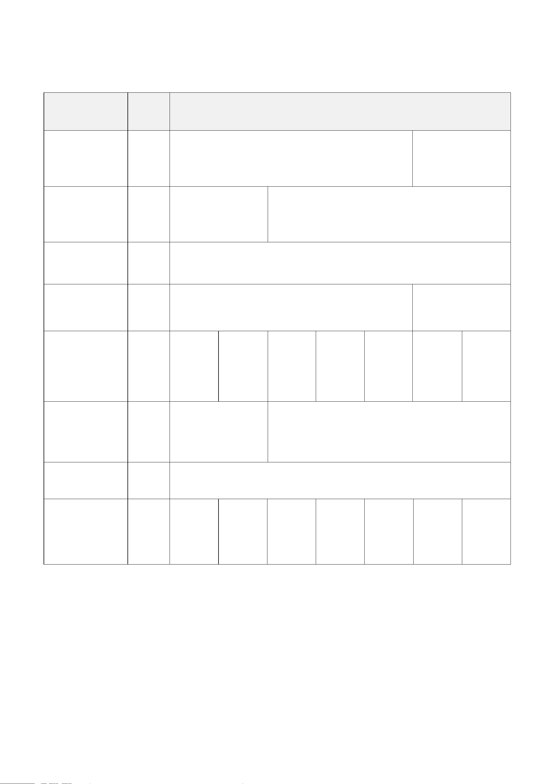
Temperature sensor: SensorType – 0x01; Channel – 0x00
Humidity sensor: SensorType – 0x02; Channel – 0x01
(1) SetGlobalCalibrateReq
Calibrate temperature sensor by increasing 10°C
Channel: 0x00 (channel1); Multiplier: 0x0001 (1); Divisor: 0x0001 (1); DeltValue: 0x03E8 (1000)
Downlink: 0101000001000103E80000
Response: 8101000000000000000000 (configuration success)
8101000100000000000000 (configuration fail)
(2) Read parameters
Downlink: 0201000000000000000000
Response: 8201000001000103E80000 (configuration success)
(3) Clear all calibration
Downlink: 0300000000000000000000
Response: 8300000000000000000000
15
5.5 Example of NetvoxLoRaWANRejoin
Fport:0x20
Check if the device is connected to the network during RejoinCheckPeriod. If the device does not respond within the RejoinThreshold, it
will be rejoied back to the network automatically.
CmdDescriptor
CmdID
(1 Byte)
Payload (Var Bytes)
SetNetvoxLoRaWA
NRejoinReq
0x01
RejoinCheckPeriod
(4 Bytes, unit: 1s)
0x FFFFFFFF_DisableNetvoxRejoinFunction
RejoinThreshold
(1 Byte)
SetNetvoxLoRaWA
NRejoinRsp
0x81
Status
(1 Byte)
0x00_success
Reserved (4 Bytes, Fixed 0x00)
GetNetvoxLoRaWA
NRejoinReq
0x02
Reserved (5 Bytes, Fixed 0x00)
GetNetvoxLoRaWA
NRejoinRsp
0x82
RejoinCheckPeriod (4 Bytes, unit: 1s)
0x FFFFFFFF_DisableNetvoxRejoinFunction
RejoinThreshold
(1 Byte)
SetNetvoxLoRaWA
NRejoinTimeReq
0x03
1
st
Rejoin
Time
(2 Bytes,
unit:1 min)
2
nd
Rejoin
Time
(2 Bytes,
unit: 1 min)
3
rd
Rejoin
Time
(2 Bytes,
unit: 1 min)
4
th
Rejoin
Time
(2 Bytes,
unit: 1 min)
5
th
Rejoin
Time
(2 Bytes,
unit: 1 min)
6
th
Rejoin
Time
(2 Bytes,
unit: 1 min)
7
th
Rejoin
Time
(2 Bytes,
unit: 1 min)
SetNetvoxLoRaWA
NRejoinTimeRsp
0x83
Status
(1 Byte)
0x00_success
Reserved
(13 Bytes, Fixed 0x00)
GetNetvoxLoRaWA
NRejoinTimeReq
0x04
Reserved (15 Bytes, Fixed 0x00)
GetNetvoxLoRaWA
NRejoinTimeRsp
0x84
1
st
Rejoin
Time
(2 Bytes,
unit:1 min)
2
nd
Rejoin
Time
(2 Bytes,
unit: 1 min)
3
rd
Rejoin
Time
(2 Bytes,
unit: 1 min)
4
th
Rejoin
Time
(2 Bytes,
unit: 1 min)
5
th
Rejoin
Time
(2 Bytes,
unit: 1 min)
6
th
Rejoin
Time
(2 Bytes,
unit: 1 min)
7
th
Rejoin
Time
(2 Bytes,
unit: 1 min)
Note:
a. Set RejoinCheckThreshold as 0xFFFFFFFF to stop the device from rejoining the network.
b. The last configuration would be kept when the device is factory reset.
c. Default setting:
RejoinCheckPeriod = 2 (hr) and RejoinThreshold = 3 (times)
1
st
Rejoin Time = 0x0001 (1 min), 2
nd
Rejoin Time = 0x0002 (2 mins), 3
rd
Rejoin Time = 0x0003 (3 mins),
4
th
Rejoin Time = 0x0004 (4 mins), 5
th
Rejoin Time = 0x003C (60 mins), 6
th
Rejoin Time = 0x0168 (360 mins),
7
th
Rejoin Time = 0x05A0 (1440 mins)
d. If device loses connection from network before data are reported, the data will be saved and reported every 30 seconds after the
device is reconnected. Data will be reported based on the format of Payload + Unix timestamp. After all data are reported, the
report time will be back to the normal setting.

16
(1) Command Configuration
Set RejoinCheckPeriod = 0x00000E10 (3600s), RejoinThreshold = 0x03 (3 times)
Downlink: 0100000E1003
Response: 810000000000 (Configuration success)
810100000000 (Configuration failure)
(2) Read RejoinCheckPeriod and RejoinThreshold
Downlink: 020000000000
Response: 8200000E1003
(3) Configure Rejoin Time
1
st
Rejoin Time = 0x0001 (1 min), 2
nd
Rejoin Time = 0x0002 (2 mins), 3
rd
Rejoin Time = 0x0003 (3 mins),
4
th
Rejoin Time = 0x0004 (4 mins), 5
th
Rejoin Time = 0x0005 (5 mins), 6
th
Rejoin Time = 0x0006 (6 mins),
7
th
Rejoin Time = 0x0007 (7 mins)
Downlink: 030001000200030004000500060007
Response: 830000000000000000000000000000 (Configuration success)
830100000000000000000000000000 (Configuration failure)
(4) Read Rejoin Time parameter
Downlink: 040000000000000000000000000000
Response: 840001000200030004000500060007
17
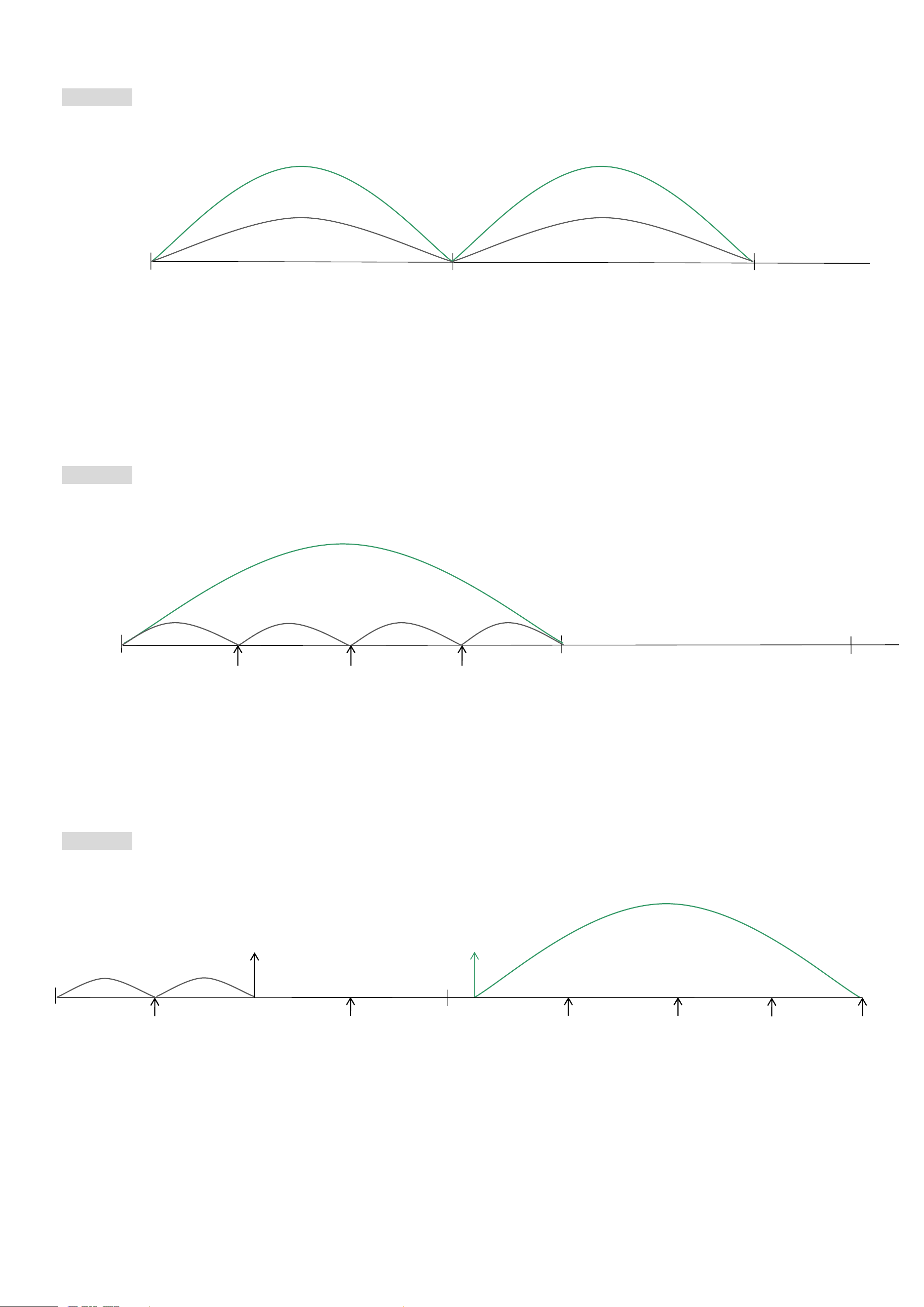
5.6 Example for MinTime/MaxTime logic
Example#1 based on MinTime = 1 hour, MaxTime = 1 hour, Reportable Change i.e. BatteryVoltageChange = 0.1V
Note: MaxTime = MinTime. Data will only be reported according to MaxTime (MinTime) duration regardless BatteryVoltageChange
value.
Example#2 based on MinTime = 15 minutes, MaxTime = 1 hour, Reportable Change i.e. BatteryVoltageChange = 0.1V.
Example#3 based on MinTime = 15 minutes, MaxTime = 1 hour, Reportable Change i.e. BatteryVoltageChange = 0.1V.
sleeping (MinTime)
sleeping (MinTime)
MaxTime
MaxTime
Wake up and collect data
REPORTS 3.6V
Wakes up and collect data
REPORTS 3.5V
Wakes up and collect data
REPORTS 3.6V
Wakes up and collects data
3.6V
Does not report
Wakes up and collects data
REPORTS 3.6V
Wakes up and collects data
REPORT 3.6V
sleeping
sleeping
sleeping
sleeping (MinTime)
MaxTime
0H
1H
15
th
M
30
th
M
45
th
M
2H
MaxTime
sleeping
sleeping
0H
30
th
M
2H 10
th
M
15
th
M
45
th
M
1H
1H 25
th
M
1H 40
th
M
1H 55
th
M
1H 10
th
M
Wakes up and
collects data
REPORTS 3.6V
Wakes up and collects data
3.5V |3.5-3.6|=0.1
REPORTS 3.5V
Wakes up and
collects data
3.5V
Does not report
Wakes up and
collects data
3.5V
Does not report
Wakes up and
collects data
3.5V
Does not report
Wakes up and collects data
3.5V Does not report
Wakes up and
collects data
3.5V
Does not report
Wakes up and
collects data
REPORTS 3.5V
Wakes up and
collects data
3.6V
Does not report
Users push the button,
REPORTS 3.5V.
Recalculate MaxTime.

18
Notes:
a. The device only wakes up and performs data sampling according to MinTime Interval. When it is sleeping, it does not collect data.
b. The data collected is compared with the last data reported. If the data variation is greater than the ReportableChange value, the device
reports according to MinTime interval. If the data variation is not greater than the last data reported, the device reports according to
MaxTime interval.
c. We do not recommend setting the MinTime Interval value too low. If the MinTime Interval is too low, the device wakes up frequently
and the battery will be drained soon.
d. Whenever the device sends a report, no matter resulting from data variation, button pushed or MaxTime interval, another cycle of
MinTime/MaxTime calculation is started.
19
6. Read R900 Data on NFC App
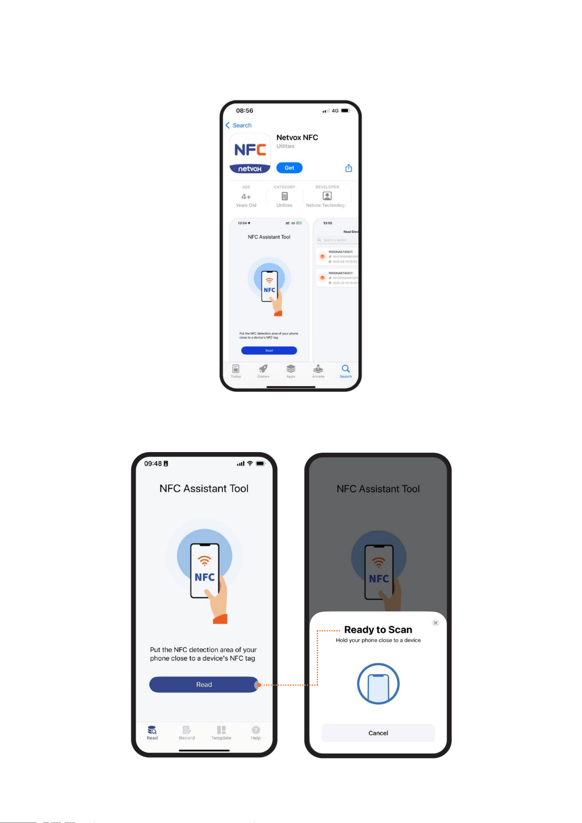
(1) Download Netvox NFC app.
Please make sure your phone supports NFC.
(2) Enable NFC in Settings and find your phone’s NFC area.
Open the app and click Read.
20
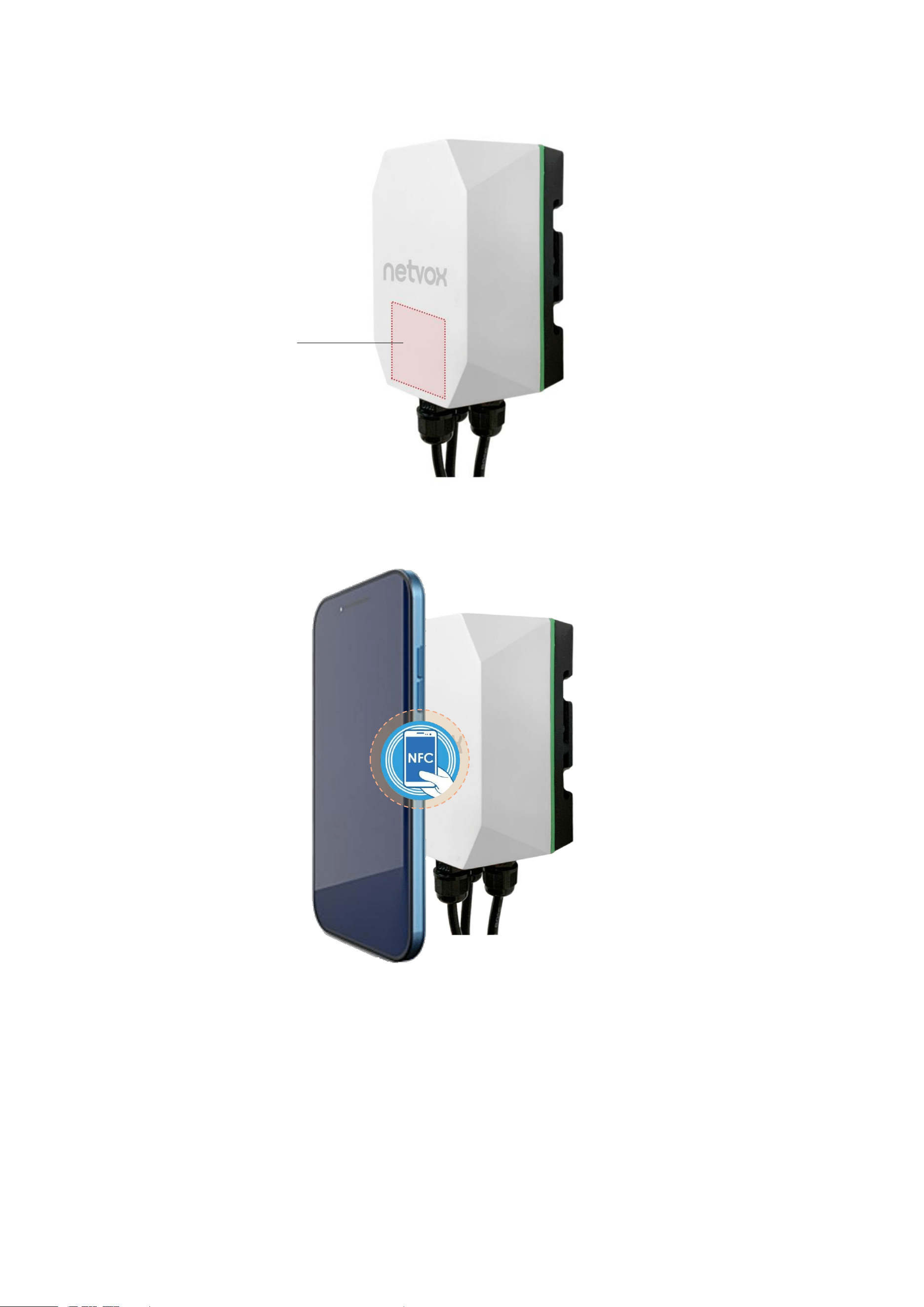
(3) Hold your phone near R900’s NFC tag.
NFC area

21
22
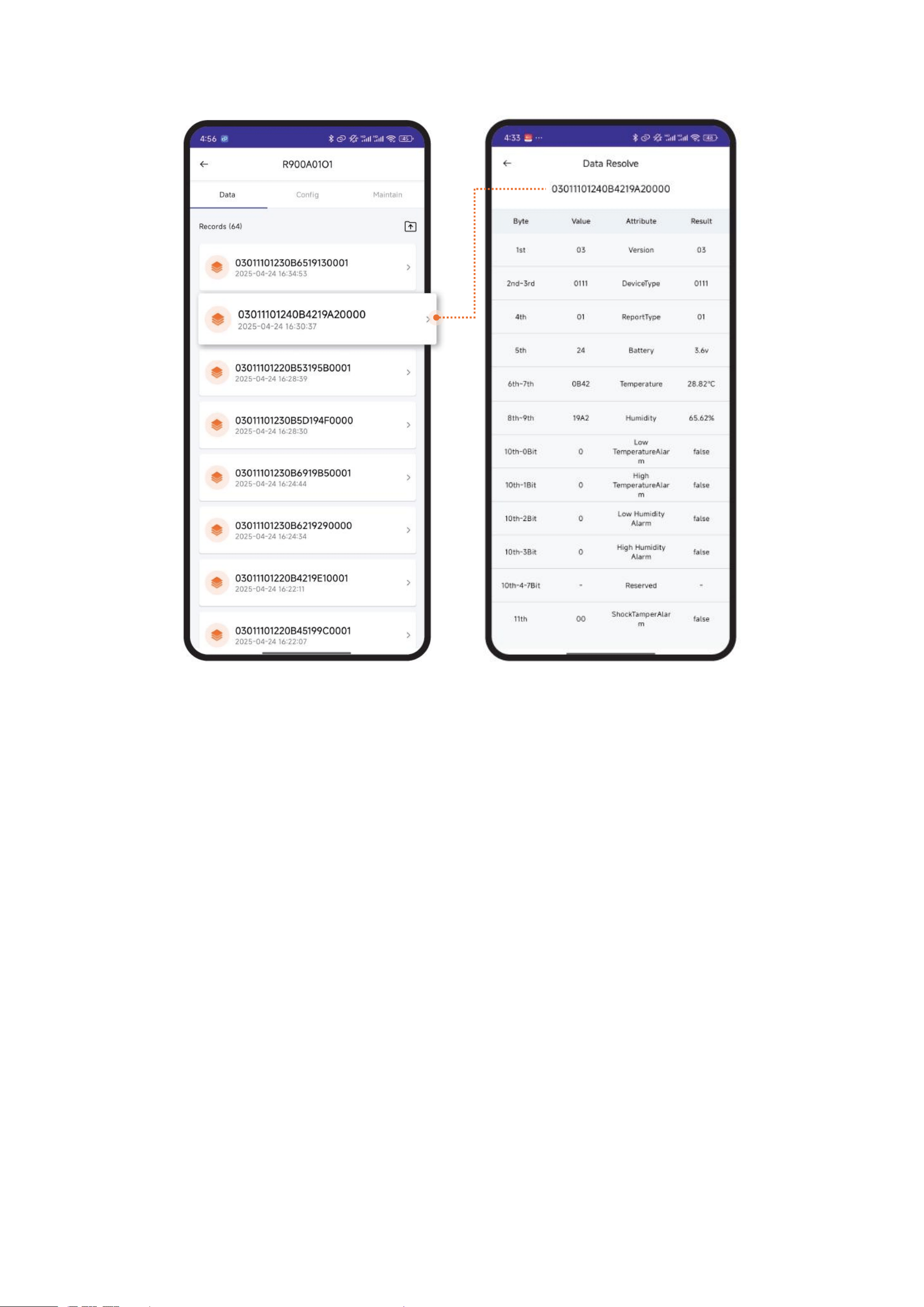
(4) After R900 is successfully read, the latest 10 data will be displayed.
Select a data and go to the Data processing.
23
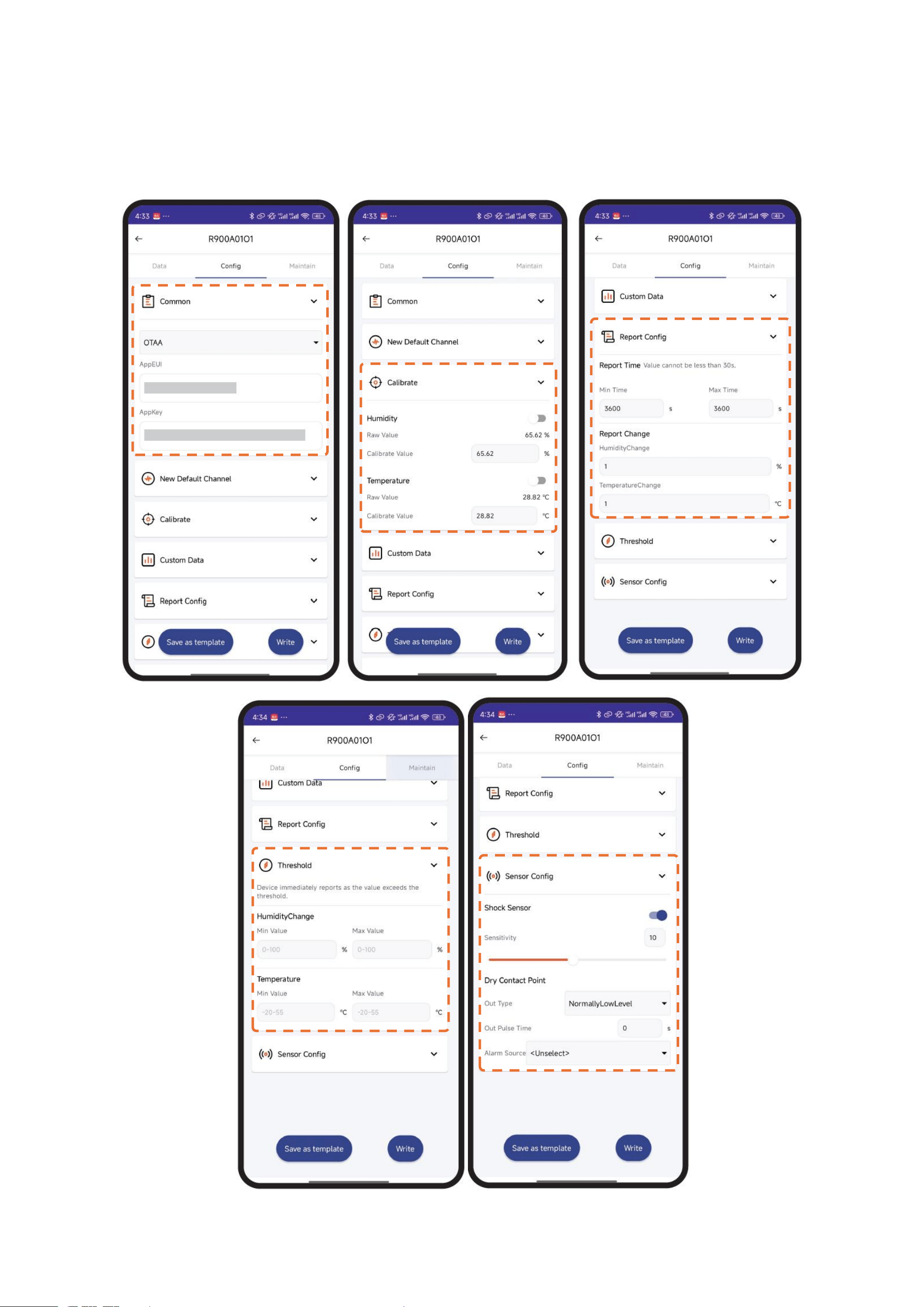
(5) Click Config to edit R900’s settings, including network connection, calibration, report configuration, threshold, and sensor
parameters.
Note: a. To configure device parameters, users need to enter password: 12345678 (default).
b. Password can be changed on the app and reset to default when R900 is factory reset.
c. Please reboot the device if the parameters of network connection are configured.
❷
❸
❹
❺
❶

24
25
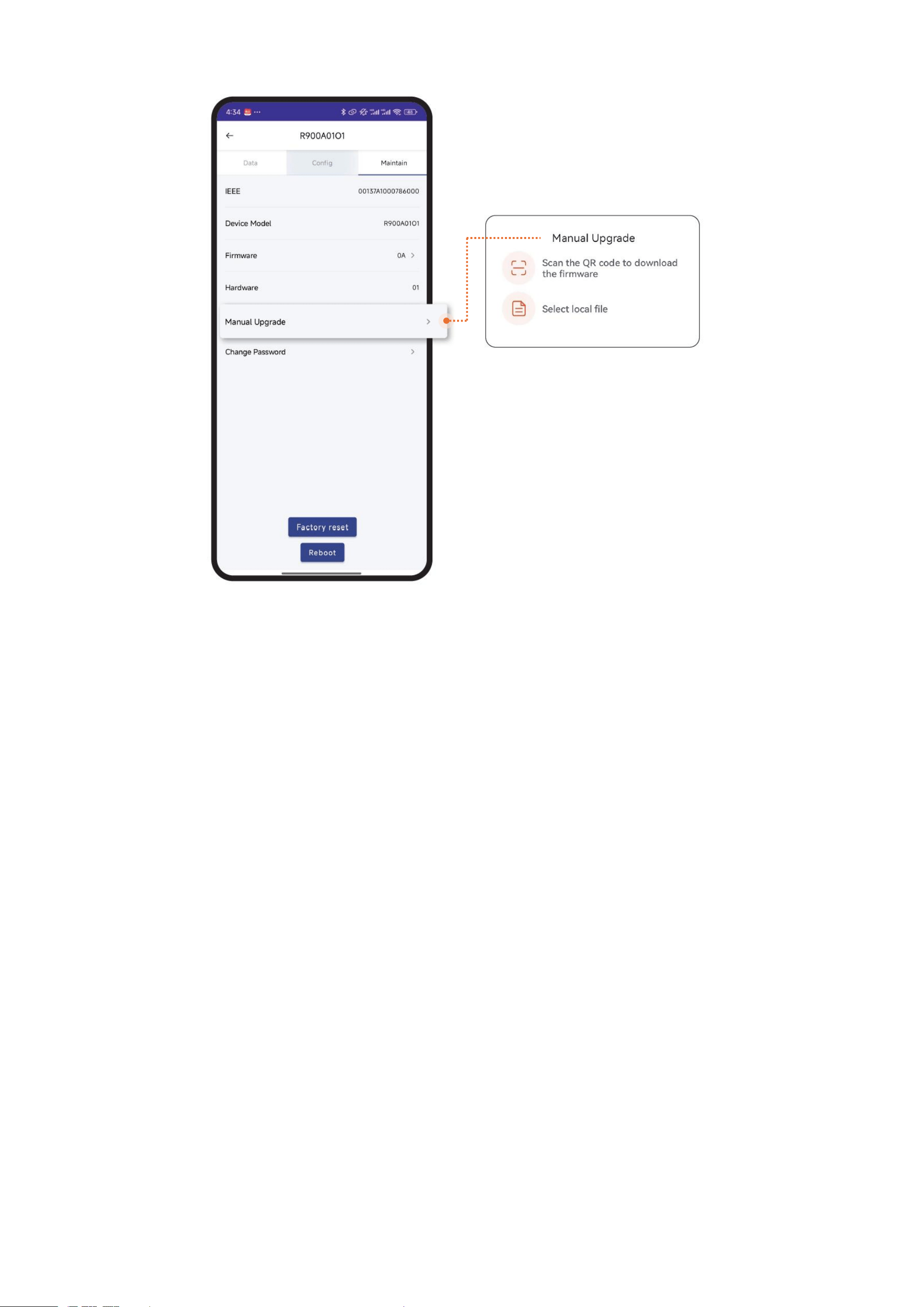
(6) Click Maintain to check R900A01O1’s info and available upgrade.
26
7. Installation
R900
Standard
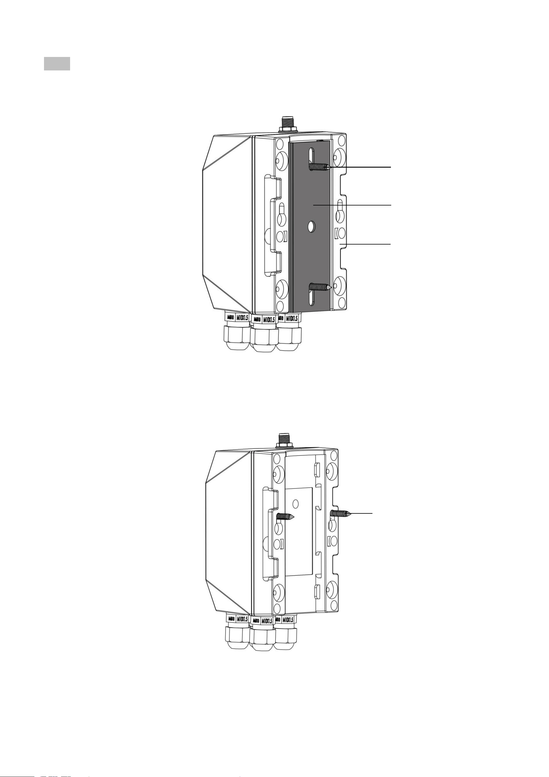
(1) Screws + Bracket
❶ Mount the bracket on a surface with 2 counter self-tapping screws.
❷ Hold R900 and slide down to connect the base and bracket.
(2) Screws
❶ Mount 2 countersunk self-tapping screws or expansion bolts on the wall.
The distance between the two screws should be 48.5mm. The gap between the bottom of the screw head and the wall should be 3mm.
❷ After the screws are mounted, align the holes of the base with the screws.
❸ Move R900 down to clamp it.
Bracket
Base
Countersunk self-tapping screw
(diameter = 4mm)
Countersunk self-tapping screw
(Thread diameter 3mm; Head diameter < 7mm)
27
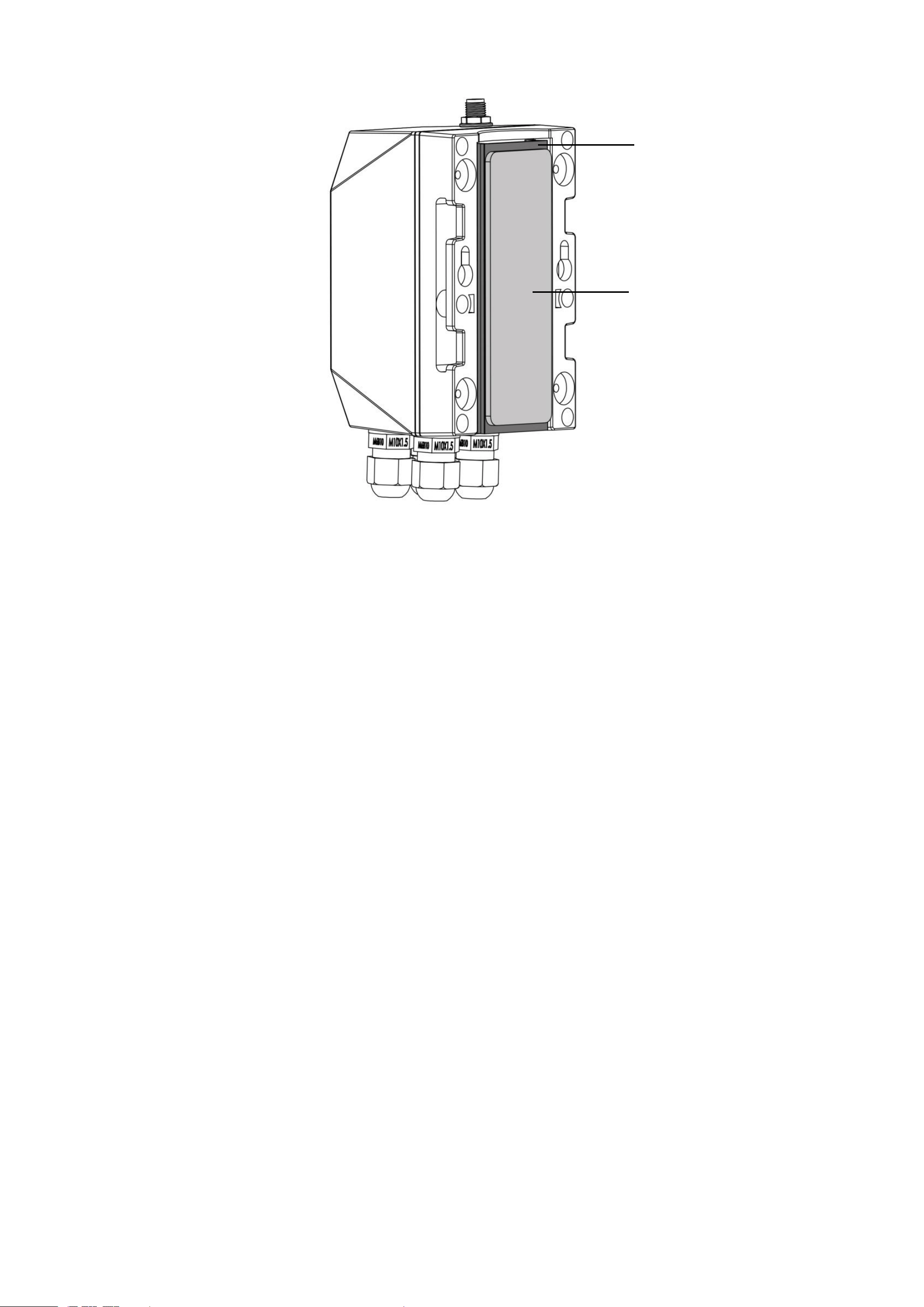
(3) Double-Sided Tape
❶ Stick the double-sided tape on the bracket.
❷ Peel the liner and fix R900 on the surface.
❸ Press to ensure R900 is firmly installed.
Note: Please make sure the surface is clean and dry before applying double-sided tape.
Double-sided tape
Bracket
28
Optional
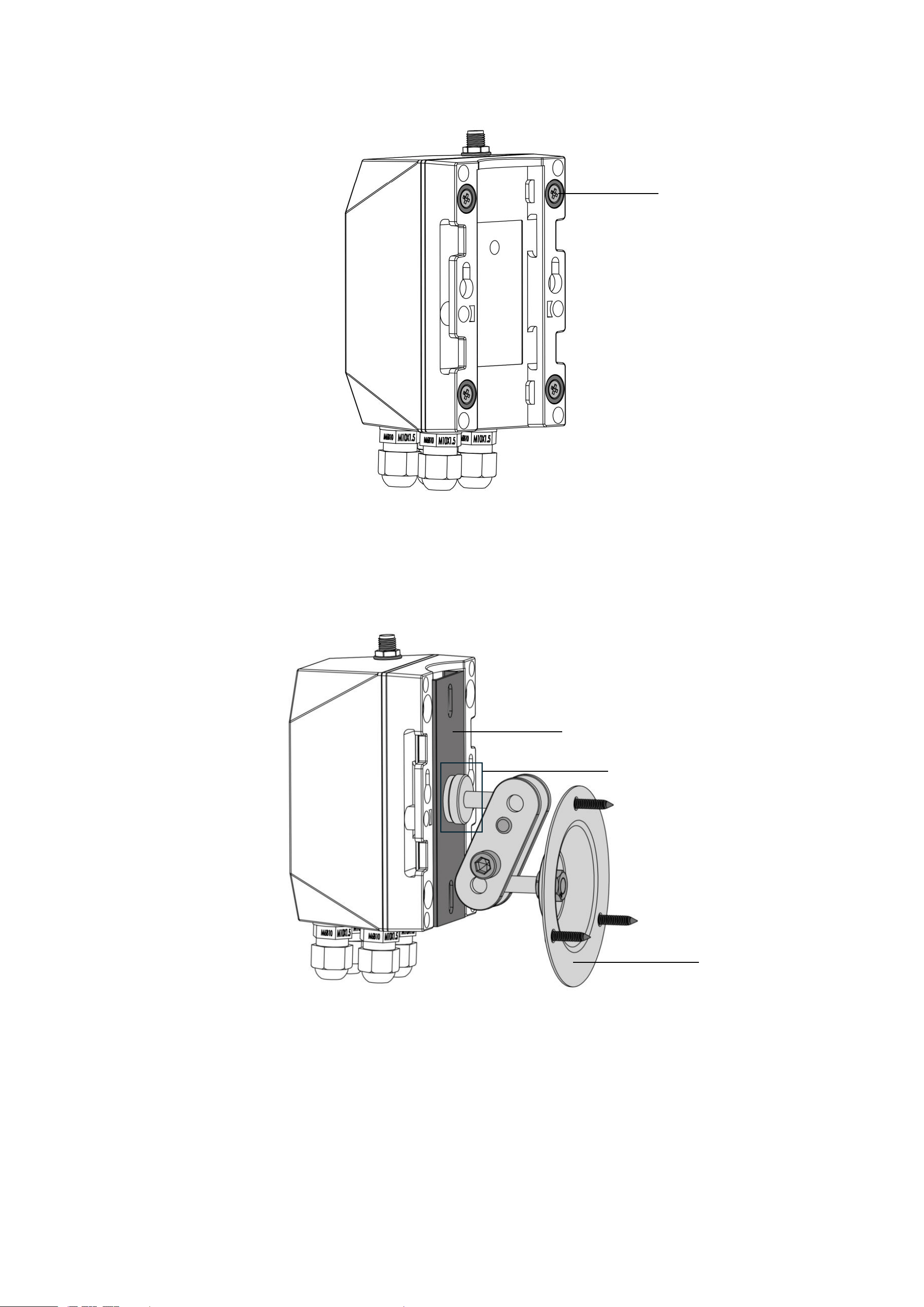
(1) Magnet
❶ Fix the R900 on a metal surface.
(2) Swivel Bracket
❶ Insert a 1/4-inch screw thread into the hole of the bracket.
❷ Tighten the thread with a nut.
❸ Mount the swivel bracket with self-tapping screws and expansion bolts.
❹ Hold R900 and slide down to connect the base and bracket.
Magnet
Bracket
1/4-inch screw thread and nut
swivel bracket
29
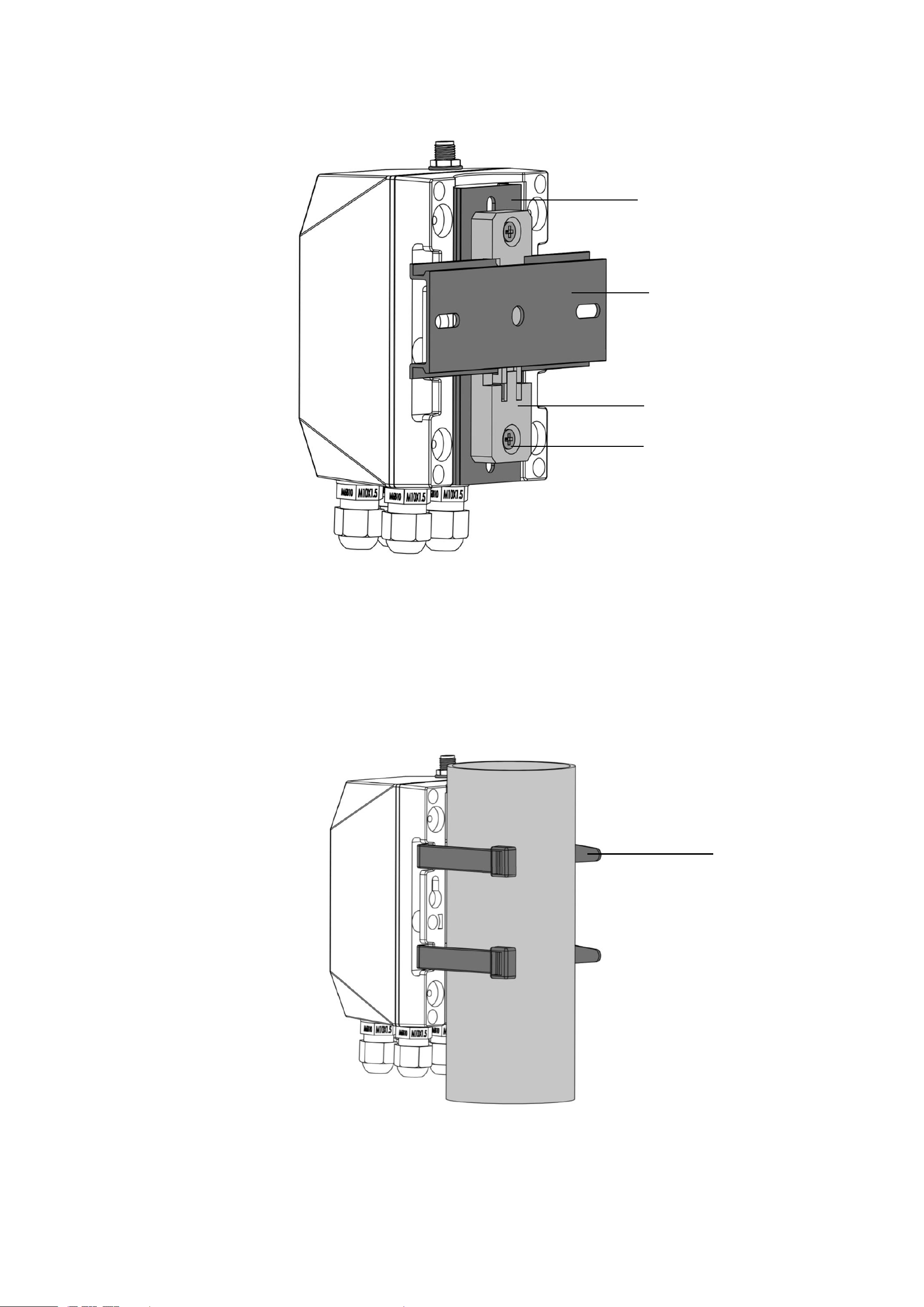
(3) DIN Rail
❶ Mount the rail buckle onto R900’s bracket with countersunk head machine screws and nuts.
❷ Snap the buckle onto the DIN rail.
❸ Hold R900 and slide down to connect the base and bracket.
Prepared by customers
(1) Cable Tie
❶ Insert cable ties through the holes of the base.
❷ Insert the pointed end through the slot.
❸ Tighten the cable ties and make sure R900 is fixed firmly around a column.
Bracket
C45 DIN rail
Buckle
Countersunk head machine
screw and nut
Cable tie

30
8. Battery Passivation
Many Netvox devices are powered by 3.6V ER14505 / ER18505 Li-SOCl2 (lithium-thionyl chloride) batteries that offer many
advantages including low self-discharge rate and high energy density. However, primary lithium batteries like Li-SOCl2 batteries
will form a passivation layer as a reaction between the lithium anode and thionyl chloride if they are in storage for a long time or
if the storage temperature is too high. This lithium chloride layer prevents rapid self-discharge caused by continuous reactions
between lithium and thionyl chloride, but battery passivation may also lead to voltage delay when the batteries are put into
operation, and our devices may not work correctly in this situation.
As a result, please make sure to purchase batteries from reliable vendors, and it is suggested that if the storage period is more
than one month from the date of battery production, all the batteries should be activated. If encountering the situation of battery
passivation, please activate the battery with 67Ω load resistance for 8 minutes to eliminate hysteresis in batteries.
9. Important Maintenance Instructions
Kindly pay attention to the following to achieve the best maintenance of the product:
• Keep the device dry. Rain, moisture, or any liquid might contain minerals and thus corrode electronic circuits. If the device
gets wet, please dry it completely.
• Do not use or store the device in a dusty or dirty environment. It might damage its detachable parts and electronic
components.
• Do not store the device under extremely hot conditions. High temperatures can shorten the life of electronic devices, destroy
batteries, and deform or melt some plastic parts.
• Do not store the device in places that are too cold. Otherwise, when the temperature rises, moisture that forms inside the
device will damage the board.
• Do not throw, knock, or shake the device. Rough handling of equipment can destroy internal circuit boards and delicate
structures.
• Do not clean the device with strong chemicals, detergents, or strong detergents.
• Do not apply the device with paint. Smudges might block the device and affect the operation.
• Do not throw the battery into the fire, or the battery will explode. Damaged batteries may also explode.
All of the above applies to your device, battery, and accessories. If any device is not operating properly, please take it to the
nearest authorized service facility for repair
10. FCC Statement:
This device complies with part 15 of the FCC Rules. Operation is subject to the following two conditions: (1) This device may
not cause harmful interference, and (2) this device must accept any interference received, including interference that
may cause undesired operation.This equipment has been tested and found to comply with the limits for a Class B
digital device, pursuant to part 15 of the FCC Rules. These limits are designed to provide reasonable protection
against harmful interference in a residential installation. This Equipment generates,uses and can radiate radio
frequency energy and,if not installed and used in accordance with the instructions,may cause harmful interference to radio
communications.However,there is no guarantee that interference will not occur in a Particular installation.If thise
quipment does cause harmful interference to radio or television reception, which can be determined by turning the equipment

31
off and on, the user is encouraged to try to correct the interference by one or more of the following measures:
—Reorient or relocate the receiving antenna.
—Increase the separation between the equipment and receiver.
—Connect the equipment into an outlet on a circuit different from that to which the receiver is connected.
—Consult the dealer or an experienced radio/TV technician for help.
Caution: Any changes or modifications not expressly approved by the party responsible for compliance could void the user's
authority to operate the equipment.
This equipment complies with FCC radiation exposure limits set forth for an uncontrolled environment. This transmitter must
not be co-located or operating in conjunction with any other antenna or transmitter.