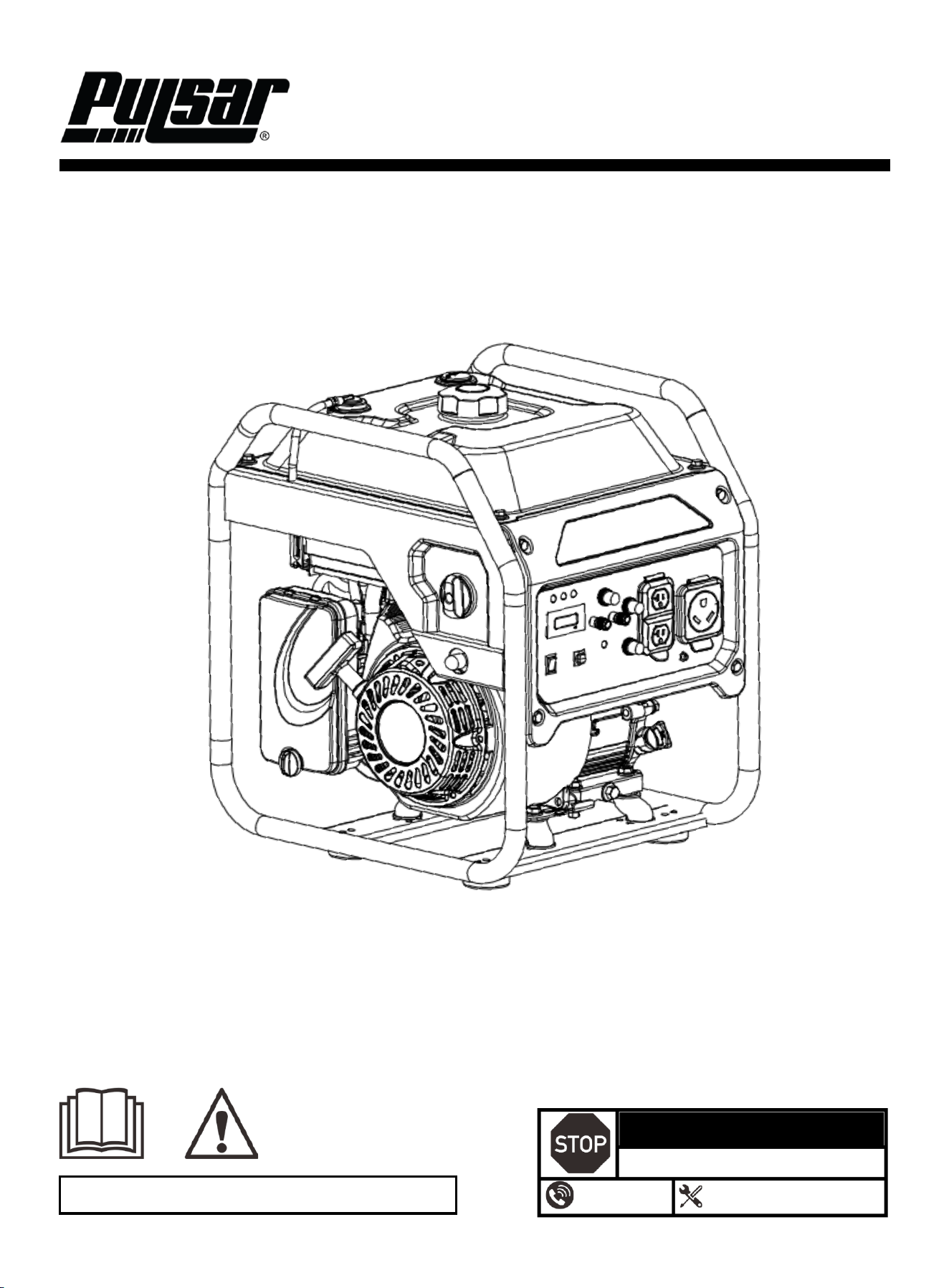
5250-Watt Dual Fuel Open Frame Inverter Generator
OPERATOR'S MANUAL
Warning: The Engine Exhaust from this product contains chemicals known to the
State of California to cause cancer, birth defects or other reproductive harm.
DO NOT RETURN TO STORE!
HAVE QUESTIONS OR NEED SERVICE?
1-866-591-8921
support@pulsar-products.com
Model: PGX5250BiXCO
Caution:
⚫ Before using your generator, please read this manual carefully to understand proper use.
⚫ Keep this manual with the generator.
1
Table of Contents
Table of Contents ………………………………….…...…..1
Instruction …………………………………………….……..1
Safety Warnings and Notices ………………………...….1
Safety Instructions …………………………………………2
Components…………………………………………………4
Control Panel ……………………………………………..…5
Preparation………………………………………………………6
Operation………………………………………………………...8
Maintenance …………………………………………..………11
Specifications ……………………….………………......……14
Troubleshooting Guide ……………….……………….….…15
Electrical Schematic……………………………………….…17
Introduction
Thank you for choosing Pulsar Products!
This manual provides instructions on how to safely and
correctly operate your generator. Please read and fully
understand this manual before using your generator. If you
have any questions, contact us at 1-866.591.8921
(Monday–Friday) or at support@pulsar-products.com
before using your generator.
All details and images in this manual are believed to be
accurate at the time of publication. Pulsar Products
reserves the right to make updates to this manual at any
time. For the latest updates, please contact Pulsar Support
at 866.591.8921 or support@pulsar-products.com.
This manual is a permanent part of the generator. If the
generator is resold, please include this manual with it.
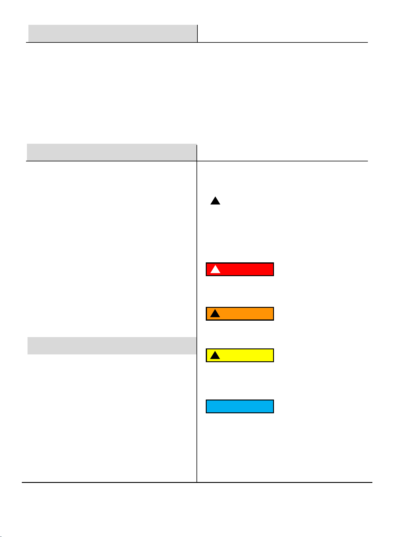
DANGER
!
DANGER indicates an imminently hazardous
situation which, if not avoided, will result in death
or serious injury.
WARNING
!
WARNING indicates a potentially hazardous
situation which, if not avoided, could result in
death or serious injury.
CAUTION
!
CAUTION indicates a potentially hazardous situation
which, if not avoided, may result in minor or moderate
injury. It may also be used to alert against unsafe
practices.
NOTICE
Failure to follow the instruction may result in the
damage to your generator and other property.
Safety Warnings and Notices
WARNING: Save This Manual
for Future Reference
This manual contains important information regarding
the safety, operation, maintenance, and storage of this
product. Before use, you must read and fully
understand all cautions, warnings, instructions, and
product labels. Failure to do so could result in serious
personal injury and/or property damage.
Safety Definitions
!
This safety alert symbol appears with most safety
statements. It means to pay attention and be alert, your
safety is involved! Please read and abide by the
message that follows the safety alerts symbol.
2
Safety Instructions
Follow all safety information provided in this manual and
on the generator.
Before operating the generator, you must read and
understand this manual fully and familiarize yourself with
safe operating practices.
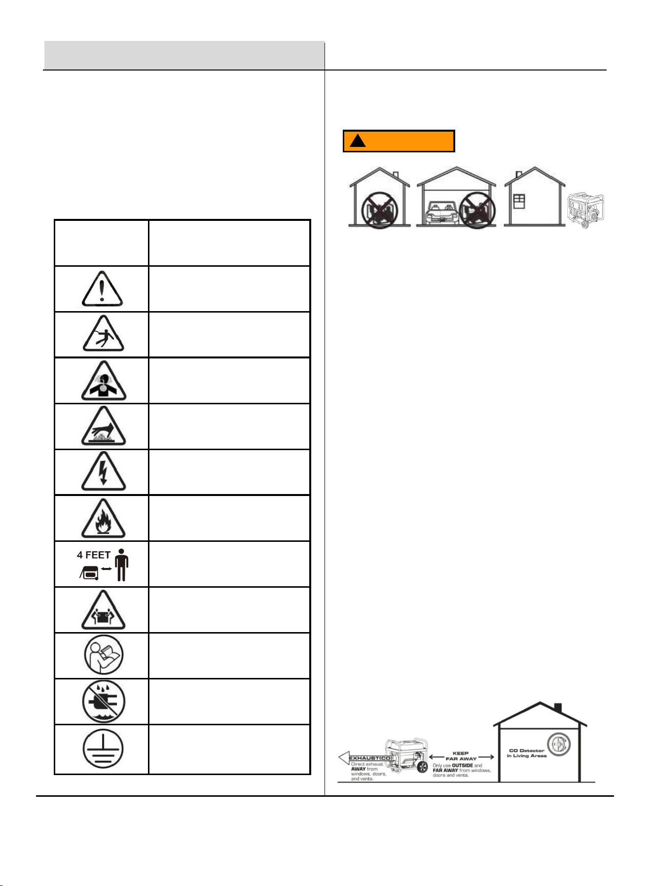
SYMBOL
DESCRIPTION
Safety Alert Symbol
Electrocution Hazard
Asphyxiation Hazard
Burn Hazard. DO NOT touch hot
surfaces.
Electrical Shock Hazard
Fire Hazard
Maintain a Safe Distance
(Minimum 4 feet).
Lifting Hazard
Read Manufacturer's Instructions and
Operator’s Manual
DO NOT Operate in Wet Conditions
Grounding. Consult a qualified
electrician to determine the necessary
grounding requirements before
operating this product.
Safety Precautions
Operate this product ONLY outdoors, far away from
windows, doors, and vents, to reduce the risk of carbon
monoxide gas buildup, which could accumulate and be
drawn into occupied spaces.
DO NOT operate this product under the influence of
alcohol, while exhausted or sleep-deprived, when drowsy
from medications, or under any condition that could impair
your judgment or prevent safe operation.
Avoid operating this product under the following
circumstances:
1. When the ground is slippery or when other conditions exist
which might make it not possible to maintain a steady posture.
2. At night, at times of heavy fog, or at any other times when
your field of vision might be limited, it would be difficult to gain a
clear view of the area.
3. During rainstorms, during lightning storms, at times of strong
or gale-force winds, or at any other times when weather
conditions might make it unsafe to use this product.
POISONOUS GAS HAZARD: Engine exhaust contains
carbon monoxide, a poisonous gas that could kill you in
minutes. You CAN NOT smell it, see it, or taste it. Even if
you do not smell exhaust fumes, you could still be exposed
to carbon monoxide gas.
Safety Symbols
WARNING
!
3
Safety Instructions
WARNING
!
Never store fuel cans or refill the fuel tank in areas
with boilers, stoves, wood fires, electrical sparks,
welding sparks, or any other sources of heat or fire
that could ignite the fuel.
Smoking while operating the product or refilling its
fuel tank is extremely dangerous. Never smoke or
vape while working with your generator.
When refilling the fuel tank, always turn off the engine
first. Carefully inspect the area to ensure there are no
sparks or open flames nearby before refueling. If any
fuel spills occur during refueling, use a dry rag to
clean up the spills before restarting the engine.
After refueling, securely screw the fuel cap back onto
the tank and move the product at least 3 meters (10
feet) away from the refueling area before restarting
the engine.
Additionally, be aware that starter cord kickback
(rapid retraction) can pull your hand or arm toward the
engine, potentially causing fractures, sprains, or other
serious injuries.
WARNING
!
Turn the generator OFF and allow it to cool for at least 2
minutes before removing the fuel cap. Loosen the cap slowly
to relieve any built-up pressure.
⚫ Fill or drain fuel tank outdoors.
⚫ DO NOT overfill the tank. Allow space for fuel expansion.
⚫ If fuel spills, wipe it up and let the area dry before starting the
engine.
⚫ Keep fuel away from sparks, open flames, heat, and other
ignition sources.
⚫ Check the fuel lines, fuel tank, fuel cap, and fittings regularly
for cracks or leaks. Replace components if needed.
⚫ Never smoke or vape near the generator or fuel.
Fuel and its vapors are extremely flammable and
explosive which could cause burns, fire, or
explosion resulting in death or serious injury and/or
property damage.
When Adding or Draining Gasoline
Before starting your generator, you must read
and understand the manual and familiarize
yourself with safe operating practices. Improper
treatment of the generator could damage it and
shorten its lifespan.
Keep the generator frame dry, clean, and free of oil
or fuel residue.
Before Starting the Unit
⚫ Never operate this product in enclosed or partially
enclosed spaces, including homes, garages, sheds,
basements, or crawlspaces, even if using fans or
open windows and doors for ventilation. Carbon
monoxide can build up quickly and linger for hours,
even after the engine is off.
⚫ Install battery-operated or plug-in carbon
monoxide alarms with battery backup as per the
manufacturer's instructions. Most smoke alarms do
not detect carbon monoxide.
⚫ Position the product downwind and direct the
exhaust away from occupied spaces. If you
experience symptoms like dizziness, weakness, or
nausea, immediately turn off the product, move to
fresh air, and seek medical attention, as these may
indicate carbon monoxide poisoning.
4
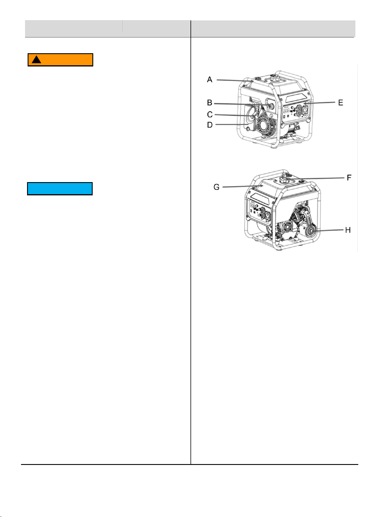
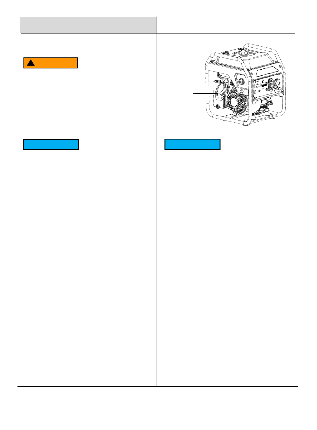
Components
When Starting the Unit
Ensure the spark plug, muffler, fuel cap, and air
cleaner are properly in place.
DO NOT crank the engine with the spark plug removed.
Safety Instructions
WARNING
!
Never touch the Muffler, spark plug, or any other
metal parts of the inverter generator while it is
operating or immediately after shutdown, as this
could result in serious burns or electric shock.
NOTICE
⚫ Use the generator only for its intended applications.
⚫ Operate the generator only on solid, level surfaces.
⚫ DO NOT insert any objects through the cooling slots.
⚫ DO NOT expose the generator to excessive
moisture, dust, dirt, or corrosive vapors.
⚫ If connected devices overheat, turn them off and
disconnect them from the generator immediately.
Shut off the generator if:
⚫ Electrical output is lost.
⚫ Equipment emits sparks, smoke, or flames.
⚫ The unit vibrates excessively.
A. Generator Frame
B. Fuel Switch
C. Recoil Start
D. Air Filter
E. Control Panel
F. Fuel Cap
G. Fuel Tank
H. Muffler
5
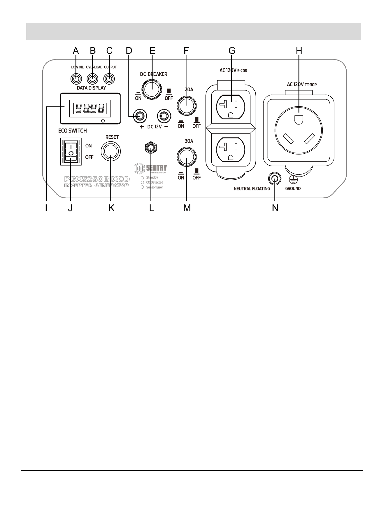
Control Panel
A. Low Oil Indicator: This indicator illuminates when the oil level in the crankcase falls below the safe operating limit. In
such cases, the generator will automatically shut off the engine to prevent damage.
B. Overload Indicator: This light indicates that the generator is overloaded and may need to be disconnected from excess
electrical loads.
C. Output Ready Indicator: Illuminates when the generator is operating normally, indicating that it is producing power and
ready for use.
D. DC Terminal: DC 12V, 8.3A
E. DC Breaker: Circuit breaker limits the current delivered through the DC Terminal to 8.3 amps.
F. 20 Amp AC Circuit Breaker: Circuit breaker limits the current delivered through the NEMA 5-20R receptacle to 20 amps.
G. 120 Volt AC, 20 Amp Duplex NEMA 5-20R Receptacle: This receptacle is rated for a maximum of 20 amps.
H. 120 Volt AC, 30 Amp NEMA TT-30R Receptacle: This receptacle can supply a maximum of 30 Amps.
I. Data Display: Frequency, Voltage, Total Runtime, and Current Runtime—one at a time, selectable by pressing the button.
J. ECO Switch: Minimizes engine speed, noise, and fuel consumption under light electrical load.
K. Overload Reset: Protects the inverter from overload. Reduce load as necessary and press to reset.
L. CO Sensor: Detects the presence of carbon monoxide and may shut down the unit automatically for safety.
M. 30 Amp AC Circuit Breaker: Circuit breaker limits the current delivered through the NEMA TT-30R receptacle to 30
amps.
N. Ground Terminal: Used to externally ground the generator, enhancing safety during operation.
6
Add Engine Oil
NOTICE
Failure to follow this instruction may result in damage
to your generator and other property.
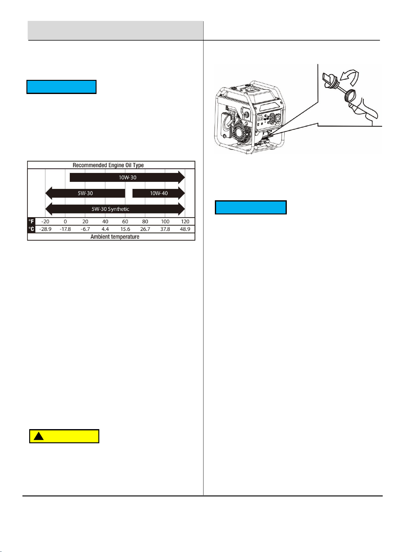
If you are operating the generator in extreme
temperatures, please refer to the following chart for
the recommended oil type.
The generator is shipped without engine oil. Do not start
the engine without ensuring it has sufficient oil.
1. Place the generator on a level surface. Make sure the
engine is OFF before adding or checking oil.
2. Unscrew the oil access cover and remove the cover from
the side panel. Unscrew the oil dipstick from the engine.
3. Using an oil funnel or appropriate dispenser, slowly add
oil into the oil fill, being careful not to overfill the unit. Fill
the crankcase to the upper fill line so you can visually
see the oil coming halfway up the oil fill threads.
4. Reinstall the oil dipstick and tighten it securely. Wipe off
any spilled oil.
5. Reinstall the oil access cover. Turn the oil access cover
to the locked position to secure it in place.
NOTICE
Recommended Engine Oil:
⚫ Oil Type: SAE 10W-30
⚫ Oil Grade: API Service SE or higher
⚫ Engine Oil Capacity: 20 fl oz (600ml)
Residual oil from the factory may remain in the
engine. Add oil slowly to prevent overfilling. Once oil
has been added, the oil level should be 1-2 threads
below the fill hole. DO NOT screw in the dipstick while
checking the oil level.
During the first 5 hours of operation (the break-in
period), check the oil level frequently and operate at
or below 50% of the running watt rating. Vary the
electrical load periodically to promote heating and
cooling of the stator windings, which helps seat the
piston rings.
This engine is equipped with a low-oil shutoff system
that automatically stops operation when oil levels
become critically low. Refer to the Maintenance
section for service intervals.
Preparation
Always keep the generator level. Tilting the unit
during filling may cause oil to enter incorrect engine
compartments, resulting in potential damage.
CAUTION
!
7
Preparation
WARNING
!
Gasoline is extremely flammable. Never smoke or vape
anything near fuel. You must stop the engine and allow
it to cool before refueling. Select outdoor bare ground
for fueling and move the generator at least 3m (10 ft)
away from the fueling point before starting the engine.
Gasoline can expand; do not fill the tank to the top.
Leave at least 1.5 inches of open space. Gasoline
fumes are explosive, so never fill the tank near an open
flame, and always check for spills.
To ensure smooth operation, use only fresh gasoline
with an octane rating of 87. Never use old gasoline and
avoid introducing dirt or water into the fuel tank.
Gasoline ages in the tank, which may make future
starts difficult. Do not store the generator for extended
periods with gasoline in the tank.
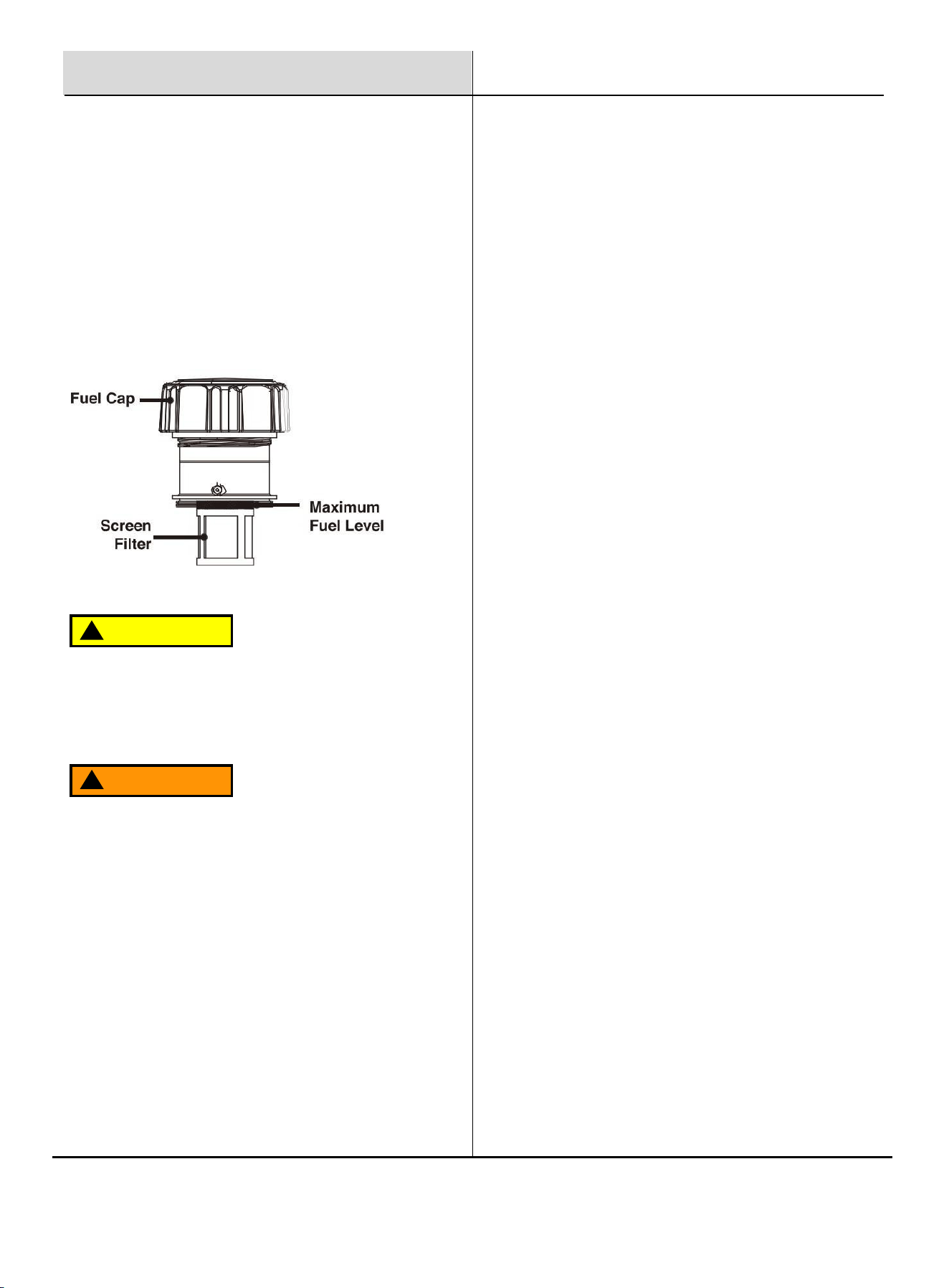
Remove the fuel cap and place it in a clean location.
Fill the fuel tank to no more than 80% capacity.
Securely replace the fuel cap and wipe up any spills.
CAUTION
!
⚫ Ensure the generator is on a solid, flat, level surface.
⚫ Unscrew the fuel cap and set it aside.
⚫ Slowly add gasoline to the fuel tank, taking care not to
overfill. The fuel gauge on the top indicates the fuel level.
⚫ Replace the fuel cap and wipe up any spilled gasoline with
a dry cloth, then safely remove the cloth from the area.
Fuel the Unit
Grounding the Generator
Attach a grounding wire if required by local code:
⚫ Connect a suitable grounding wire to the grounding
stud on the control panel and tighten the nut.
⚫ Attach the other end to a copper or brass grounding
rod driven into the earth.
A commonly acceptable grounding wire is a No. 12
AWG (American Wire Gauge) stranded copper wire.
Since grounding codes vary by location, consult a local
electrician to ensure compliance with local regulations.
8
Fuel And Chain Oil
Operation
Operating the Generator
Location: Do not operate the generator inside any building,
garage, basement, crawlspace, shed, RV compartment, or
other enclosed spaces.
Outdoor Setup: Avoid operating the generator in a truck
bed, camper, trailer, or any other confined location, such as
under staircases or next to walls, which may restrict airflow
or exhaust.
Weather Conditions: Never operate or store the generator
in wet conditions (e.g., rain or snow) to avoid serious injury
or death from electrocution.
Clearances: Maintain a minimum of 5 feet (1.5 meters) of
clearance from all combustible materials. Ensure at least 5
feet (1.5 meters) of airflow clearance on all sides for cooling,
maintenance, and safe exhaust flow.
Ventilation: Position the generator in a well-ventilated area
and away from air intake vents or confined spaces where
exhaust fumes could enter.
Wind Direction: Be mindful of wind direction when
positioning the generator to prevent exhaust from flowing
toward occupied spaces.
Cooling: Allow the generator to cool fully before
transporting or storing.
Failure to follow these safety precautions may result in
personal injury, damage to the generator, and may void
the manufacturer's warranty.
WARNING
!
During operation, the muffler and engine will be very
hot. Without adequate cooling space or if the generator
is blocked or enclosed, temperatures may rise quickly
and could lead to a fire.
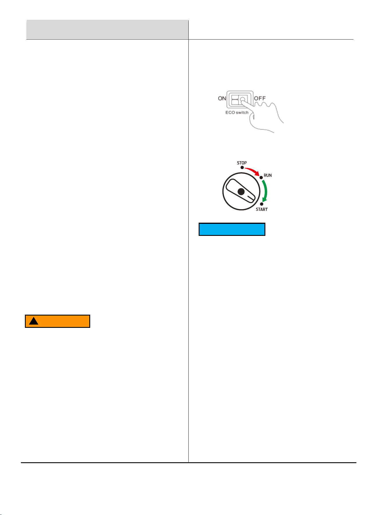
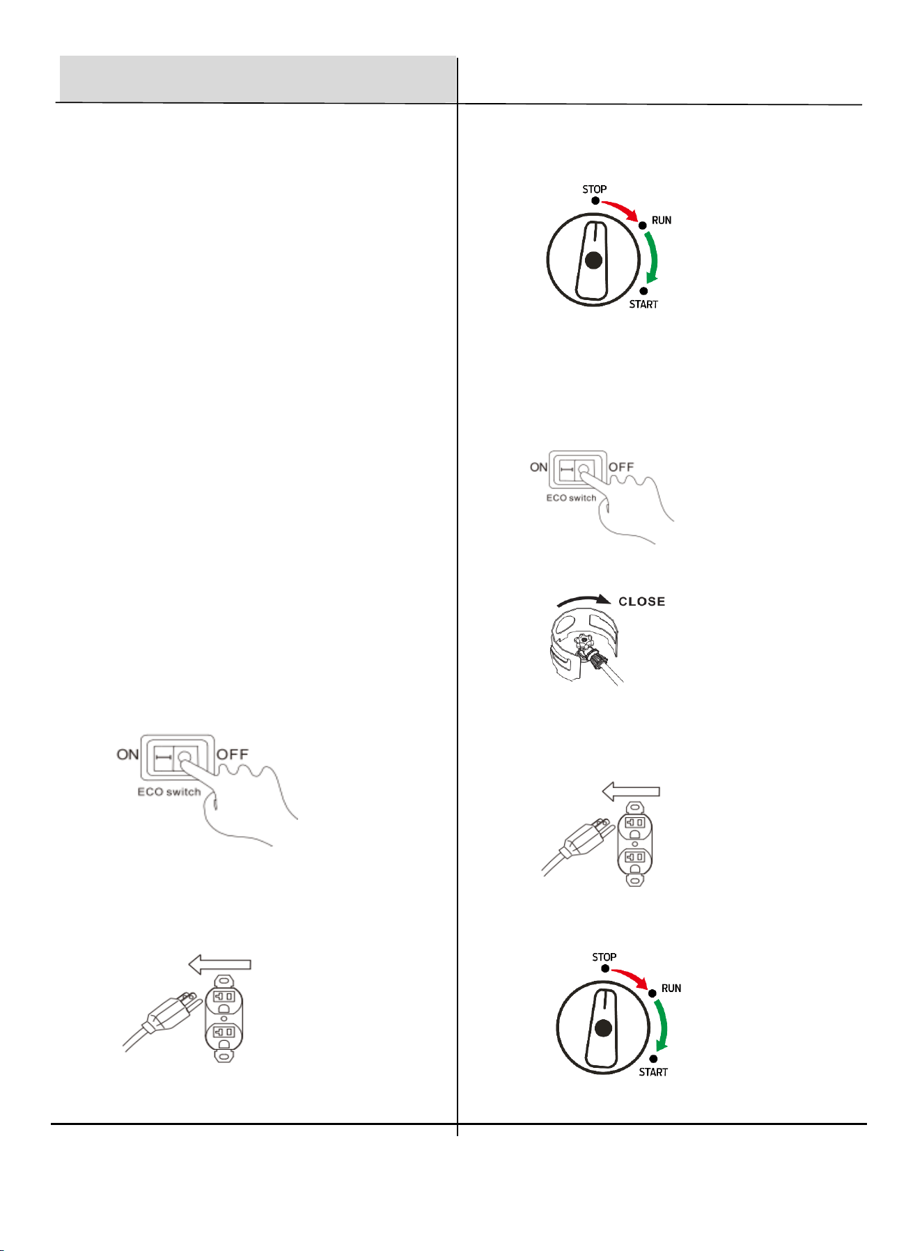
Starting the Generator with Gasoline
1. Turn the ECO switch to "OFF" position.
NOTICE
For warm engine restarts, you may turn the Fuel
Switch directly to the "RUN" position.
Cold Start: When the engine oil is below 165 °F
(74 °C), the machine is considered in cold start
condition.
Warm Start: Engine oil at or above 165 °F indicates
warm start conditions.
Due to variations in altitude, humidity, and
ambient temperature, it may be difficult for users
to accurately determine whether the engine is in
a cold or warm state.
You may safely try both the "START" and "RUN"
positions. Allow a few seconds between each
pull of the Recoil Start and observe for ignition to
avoid fuel flooding or excessive wear to the
starter rope.
2. Turn the fuel switch to the " START " position.
9
4. After the engine starts, gradually turn the Fuel
Switch to the "RUN" position.
In warm conditions, this can be done immediately.
In colder conditions, keep the switch in the "START"
position for 20–30 seconds to allow the engine to
warm up before switching to "RUN".
Always switch to "RUN" before connecting electrical
loads to the generator.
Operation
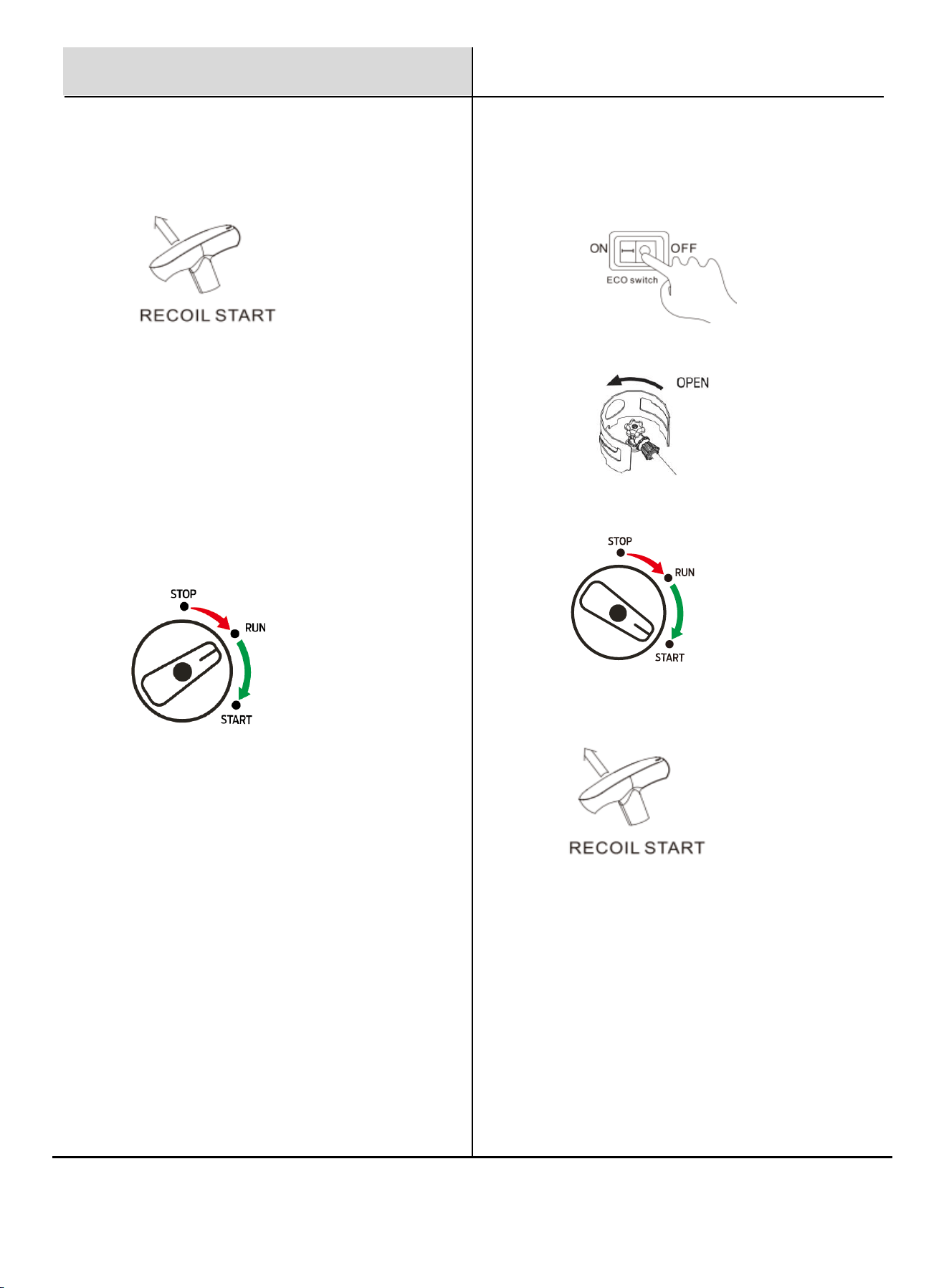
3. Pull the recoil rope until resistance is felt, let it
retract, then pull swiftly. Repeat as necessary until
the engine starts.
Starting the Generator with Propane
1. Turn the ECO switch to "OFF" position.
2. Open the LPG valve on the propane cylinder.
3. Turn the fuel switch to the "START" position. Please see the
warning and startup notice on page 8.
4. Pull the Recoil Start until resistance is felt, then let it retract
and pull swiftly. Repeat as needed until the engine start.
5. After the engine starts, gradually turn the fuel switch to the
"RUN" position.
In warm conditions, this can be done immediately.
In colder conditions, keep the switch in the "START"
position for 20–30 seconds to allow the engine to warm up
before switching to "RUN".
Always switch to "RUN" before connecting electrical loads
to the generator.
10
Operation
Stop the Generator with Gasoline
1. Turn the ECO switch to "OFF" position.
2. Unplug all connected electrical loads.
Never start or stop the generator with electrical devices
plugged in or powered on.
The OVERLOAD light may turn on briefly when
starting a large device. This is normal for loads near
the generator's capacity.
⚫ Ensure that the total combined load does not
exceed the generator’s rated running power.
⚫ If the OVERLOAD light remains on and power is
interrupted, the generator is either overloaded or
may require service.
⚫ Turn off and disconnect all devices, then shut
down the engine. Compare device wattage
requirements with the generator’s rated output and
reduce the load if necessary. Ensure adequate
ventilation around the generator.
⚫ Check if any circuit breakers have tripped and
reset them before restarting.
⚫ Restart the engine, reconnect devices gradually,
and avoid overloading the generator.
⚫ If the issue persists, contact an authorized Pulsar
Service Center for inspection and service.
Overload Indicator
Stop the Generator with Propane
1. Turn the ECO Switch to the "OFF" position.
2. Close the LPG valve on the propane cylinder.
3. Unplug all connected electrical loads.
Never start or stop the generator with electrical devices
plugged in or powered on.
4. Turn the fuel switch to the "STOP" position.
3. Turn the Fuel Switch to the "STOP" position.

11
Operation
High Altitude Operation
Operating the generator at high altitudes can affect
performance due to a richer air/fuel mixture, leading to
decreased efficiency and increased fuel consumption. It
may also cause spark plug fouling and hard starting.
Extended operation at altitudes different from the
engine’s certification may result in higher emissions.
For those using the generator above 5,000 feet (1,500
meters), a qualified technician should perform carburetor
modifications to improve performance. While these
modifications will help meet emission standards, note
that engine power will decrease by approximately 3.5%
for every 1,000-foot (300-meter) increase in altitude.
Do not exceed the generator's power capacity. Exceeding
the wattage capacity can lead to damage to both the
generator and the electrical devices connected to it.
Ensure that the generator can supply sufficient
continuous (running) and surge (starting) watts for the
devices you plan to power simultaneously.
When determining power requirements, consider the total
power needs of all connected devices using the formula:
Volts x Amps = Watts. Appliance and power tool
manufacturers typically provide rating information near
the model or serial number.
To determine power requirements:
1. Select the Devices: Identify the devices you intend
to power simultaneously with the generator.
2. Total Continuous Watts: Calculate the total
continuous (running) watts of these devices. This total
represents the power the generator must consistently
produce to keep all selected items operational.
3. Estimate Surge Watts: Determine the estimated
surge (starting) watts required. Surge wattage is the
initial burst of power needed to start electric motor-
driven tools or appliances, such as a circular saw or
refrigerator. Since not all motors start at the same
time, you can estimate total surge watts by adding the
item(s) with the highest additional surge wattage to
the continuous watt total from step 2.
Maintenance
Safety Precautions Before
Maintenance
Turn Off the Generator: Switch the generator to "OFF,"
wait for the engine to cool, and disconnect the spark plug
cable before performing any inspections, maintenance, or
cleaning.
Equipment Failure: Do not use damaged equipment. If you
notice abnormal noise, vibration, or excessive smoke,
correct the issue before further use.
Qualified Technician: Many maintenance tasks, including
those not detailed in this manual, should be performed by a
qualified technician to ensure safety. If you are unsure about
servicing the equipment or engine, please contact an
authorized Pulsar Service Center for assistance.
Cleaning, Maintenance, and
Lubrication Schedule
This schedule serves as a general guide. If performance
decreases or if the generator operates unusually, have it
inspected immediately. Maintenance needs may vary based
on factors such as duty cycle, temperature, air quality, and
fuel quality.
The following procedures are in addition to the regular
checks and maintenance outlined for the generator:
WARNING
!
Before Each Use: Check engine oil level.
Every 3 Months or 50 Hours of Use: Clean or replace the
air filter. Check/adjust idle speed.
Every 6 Months or 100 Hours of Use: Change engine oil.
Check and clean spark plug and spark arrestor.
Check/adjust valve clearance.
Yearly or Every 300 Hours of Use: Clean fuel tank,
strainer, and carburetor. Clean carbon build-up from
combustion chamber.
Every 2 Years: Replace the fuel cap if necessary.
NOTICE
Generator’s Power Capacity
12
Maintenance
Checking and Filling Fuel
WARNING
!
To Prevent Serious Injury from Fire: Always shut off
the engine while refueling.
1. Clean the fuel cap and the area around it.
2. Unscrew and remove the fuel cap.
3. Remove the strainer and discard any dirt and
debris, then replace the strainer.
NOTICE
Do not use gasoline containing more than 10% ethanol
(E10) or E85 ethanol.
Add a fuel stabilizer (such as Sta-Bil or Pri-G) to the
gasoline; failure to do so will void the warranty.
Avoid using gasoline that has been stored in a metal or
dirty fuel container, as it can introduce particles that
affect engine performance or cause damage.
4. Add fuel if needed, do not overfill.
5. Replace the fuel cap securely.
6. Wipe up any spilled fuel and allow any residue to
evaporate before starting the engine. To prevent
fire, do not start the engine while the smell of fuel
lingers in the air.
Air Filter Maintenance
1. Remove the air filter case cover.
2. Take out the foam element.
3. Wash the foam element in hot, soapy water. Never
use a solvent
NOTICE
Do not wring out the foam element when squeezing it,
as this could cause it to tear.
1. Apply a few drops of clean engine oil to the foam
element and squeeze out the excess oil. The foam
should have a light coating but not dripping. Ensure
the oil is evenly distributed for a light film across the
foam material.
2. Reinstall the foam element in the air filter box. The
engine should never run without the foam element, as
premature engine wear may result.
3. Install the air filter case cover in its original position.
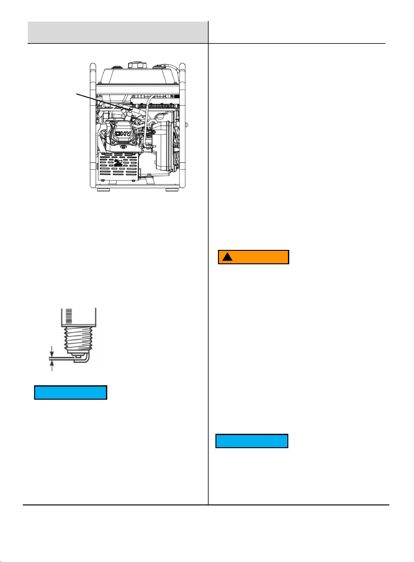
Spark Plug Maintenance
The spark plug is critical for good engine performance;
it should be removed, cleaned, inspected, adjusted,
and/or replaced regularly to maintain optimal
performance.
1. Remove the Spark Plug: Remove the spark plug boot.
Insert the spark plug tool through the hole and fit it
securely over the spark plug. Use the T-handle through
the spark plug wrench and turn it counterclockwise until
the spark plug can be removed.
Air Filter
13
NOTICE
If a torque wrench is not available, a good estimate of
the correct torque is 1/4 to 1/2 turn past finger tight.
However, the spark plug should be tightened to the
specified torque as soon as possible.
Draining the Carburetor
1. Shut off the gasoline flow.
2. Place an appropriate container under the carburetor.
3. Carefully open the drain bolt at the bottom of the
carburetor bowl, allowing the fuel to drain completely.
4. Replace the drain bolt after draining.
NOTICE
Maintenance
2. Inspect and Clean: Check the porcelain insulator
nose; it should be a light tan color. Use a wire brush to
remove any black carbon deposits. Measure the spark
plug gap according to the specified table. Adjust the
gap or replace the spark plug as necessary, ensuring
the gap is measured with a wire thickness gauge.
3. Reinstall the Spark Plug: Tighten the spark plug to
12.5 N·m (15 lb·ft). Proper tightening is crucial: If the
spark plug is too loose, it can cause the engine to
overheat. If it is over-tightened, it may damage the
threads in the cylinder head.
4. Reconnect the Spark Plug Boot: Ensure it clicks into
place. Tug gently on the boot to confirm a secure
connection.
Standard Spark Plug: BP6ES
Spark Plug Gap: 0.6-0.8 mm
Generator Storage
When the generator will remain idle for longer than 30
days, prepare the engine for storage as follows:
⚫ Cleaning: Allow the engine to cool. Open both side
access panels and blow or vacuum any dirt or debris.
Do not use water for cleaning, as it can enter the
engine and cause damage.
⚫ Fuel Treatment/Draining: Fill the fuel tank with fresh
gasoline that has been treated with a fuel stabilizer
additive (such as Sta-Bil or Pri-G). Follow the fuel
stabilizer manufacturer's recommendations for use.
⚫ Storage Area: Cover the generator and store it in a
dry, level, well-ventilated area out of reach of children,
away from ignition sources like water heaters and
furnaces.
⚫ Engine Operation During Storage: Start the engine
every 3 months and allow it to run for 15-20 minutes.
WARNING
!
Fill the fuel tank in a well-ventilated area away from
ignition sources. If the engine is hot from use, allow it
to cool before adding fuel. Do not smoke or vape
while refueling.
Aged gasoline that has not been treated with a
stabilizer must be safely drained and disposed of.
Never run old gasoline through the engine. To prevent
serious injury and fire, ensure the engine is cool
before performing any maintenance procedures.
Spark Plug

14
Product Description
5250W Dual Fuel Open Frame Inverter Generator
Engine Type
Single Cylinder, 4-Stroke, Forced Air Cooling, OHV
Displacement (cc)
223
Peak Power (Gasoline)
5250W
Rated Power (Gasoline)
4000W
Peak Power (Propane)
4700W
Rated Power (Propane)
3600W
Fuel Burn at Half Load (Gasoline)
0.38gal/h
Fuel Burn at Half Load (Propane)
1.75lb/h
Fuel Tank Capacity
2.11gal
Run Time at Half Load (Gasoline)
6 hours
Voltage Rating
120V
Frequency
60Hz
Amperage (120V Rated/Peak Gasoline)
33.33A / 43.75A
Starting Type
Recoil Start
Outlet
2*AC 120V 20A, 1*AC 120V 30A, 1*DC 12V 8.3A
Oil Type
SAE 10W-30
Oil Capacity
20fl oz (280ml)
Maximum Ambient Temperature
40°C (104°F)
Product Dimensions (in)
18.5 x14.76 x 19.69
NW (lbs)
64
Warranty
3 Years
Specifications

15
Troubleshooting Guide
Problem
What to Do
THE ENGINE WILL NOT START
Check Fuel Level: Ensure there is enough gasoline in the tank.
Fuel Filter Check: If the fuel filter is clogged, replace it with a new one.
Check Oil Level: Make sure the oil level is at the full mark. Low oil can
prevent starting in generators with a low oil shutdown feature.
Spark Plug Condition: Remove and inspect the spark plug. Clean or
replace if it appears fouled or worn. Ensure the spark plug cap is
securely attached.
Air Filter: Check the air filter for dirt or blockages.
Clean or replace if necessary.
Inspect Fuel Quality: Use fresh gasoline with an octane rating of 87 or
higher. Stale fuel may need to be drained and replaced.
Carburetor Issues: If the carburetor is fouled, it may require
cleaning or servicing.
Ignition System: If the ignition system seems faulty, consult an
authorized service center.
Fuel Valve Position: Ensure the fuel valve is set to the "ON" position.
If it’s off, fuel won’t flow to the carburetor, preventing the engine from
starting.
Fuel Valve Blockage: If the fuel valve is open but no fuel is reaching
the carburetor, the valve or fuel line could be clogged. Cleaning or
replacing the fuel valve may be necessary.
Propane No-Start: Ensure the fuel switch is set to the propane position.
Check the propane tank for sufficient fuel and ensure the connection is
secure. Verify the propane regulator is functioning; if not, it may require
replacement. Inspect the propane line for blockages or leaks and
replace if necessary.

16
Troubleshooting Guide
Problem
What to Do
GENERATOR WILL NOT
PRODUCE POWER
Check Circuit Breakers: Ensure all circuit breakers are in the "ON"
position. If any are tripped, reset them and test for power.
Verify Connections: Make sure all power cords are connected securely
and that any connected devices are operational.
Inspect for Overload: If the generator was overloaded, disconnect all
devices and let it run briefly to reset. Reconnect devices gradually,
staying within the generator’s rated capacity.
Check for Overload Indicator Light: If your generator has an overload
indicator, make sure it isn’t lit. An overload light often signals that a high-
powered device is drawing too much electricity.
Examine the Outlet Panel: Inspect the outlets for damage or debris, as
these can prevent proper electrical flow.
Inspect the Brushes and AVR (if applicable): If you’re familiar with
internal components, check the generator's brushes and automatic
voltage regulator (AVR) for wear or failure. A qualified technician should
handle this step if you’re uncertain.
Reset the Generator: Some inverter generators have reset buttons.
Follow the user manual to reset the inverter if applicable.
Professional Service: If none of the above steps restore power, it could
be an issue with internal components (e.g., alternator or inverter
module), and you may need to contact a service center for repair.
17
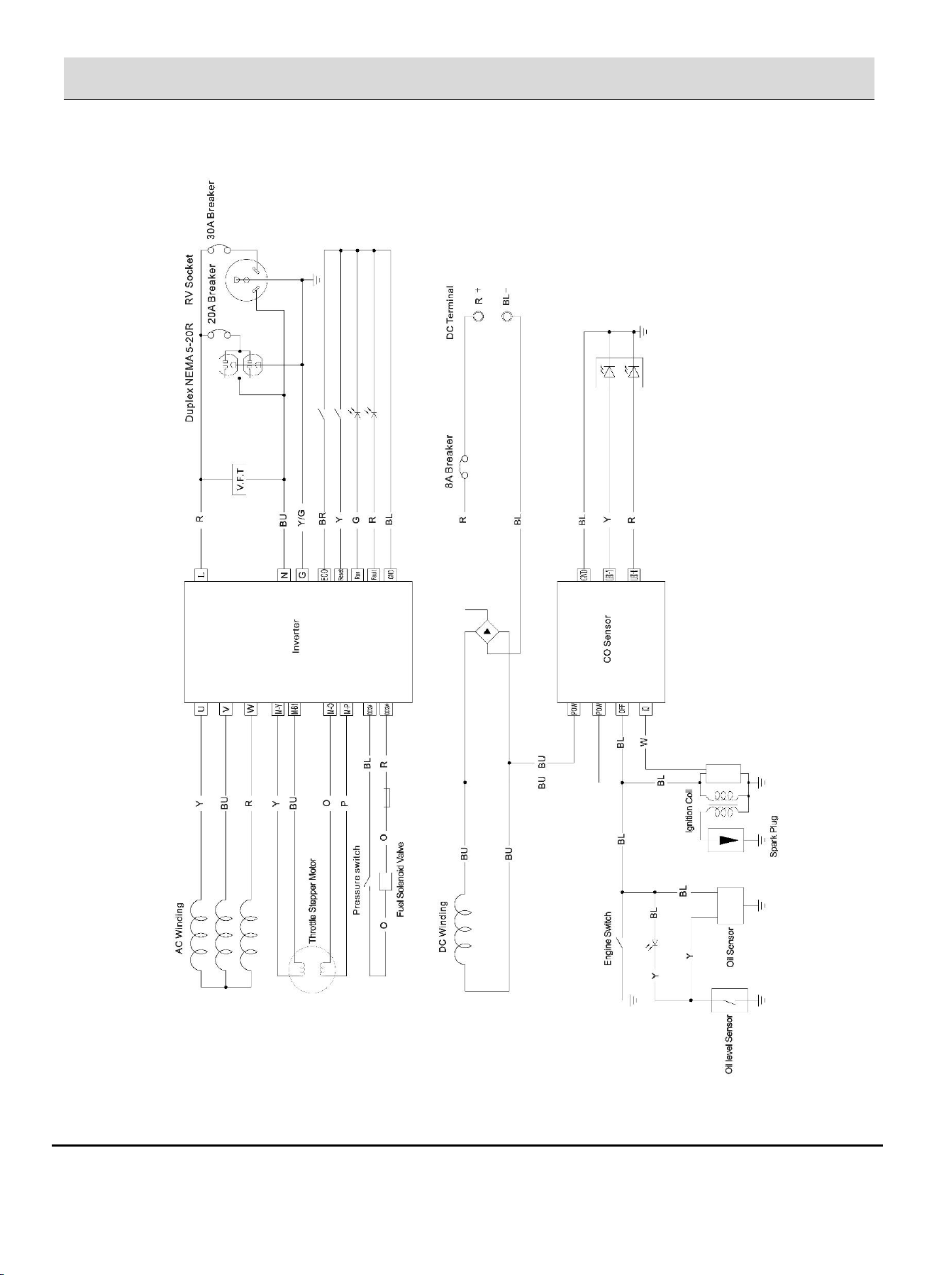
Electrical Schematic

5250-Watt Dual Fuel Open Frame Inverter Generator
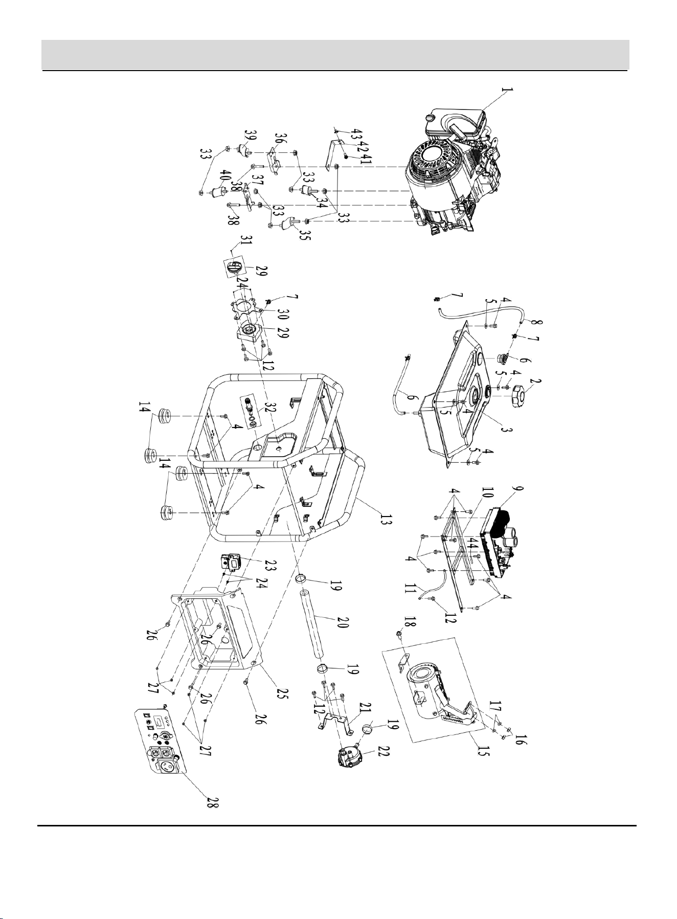
EXPLODED VIEW & PARTS LIST
Warning: The Engine Exhaust from this product contains chemicals known to the
State of California to cause cancer, birth defects or other reproductive harm.
DO NOT RETURN TO STORE!
HAVE QUESTIONS OR NEED SERVICE?
1-866-591-8921
support@pulsar-products.com
Model: PGX5250BiXCO
Caution:
⚫ Before using your generator, please read this manual carefully to understand proper use.
⚫ Keep this manual with the generator.
1
Exploded View-Generator

2
Items
Part No
Description
Qty
1
5.01.075.000037
Engine
1
2
2.55.05.128106
Fuel Cap
1
3
2.55.05.128107
Fuel Tank
1
4
2.63.01.02331
Hex Head Bolt Full Thread
17
5
2.63.01.01812
Fuel Tank Connecting Pad
4
6
2.55.06.034000
Oil Inlet Pipe
1
7
2.55.07.003800
Spring Clamp
3
8
2.55.06.008500
Oil Pipe Φ8*Φ4.5*500
1
9
2.80.04.000146
Inverter
1
10
2.80.03.000063
Mounting Plate Of Inverter
1
11
2.56.10.014818
Ground Wire
1
12
2.63.01.01756
Hex Head Bolt M6*12
9
13
2.57.01.108208
Frame
1
14
2.61.05.010302
Shock Absorbing Floor Mats
4
15
2.50.12.044200
Muffler
1
16
2.63.01.00287
Type 1 Hexagonal Nut
2
17
2.63.01.01705
Standard Spring Washer
2
18
2.63.01.02509
Hex Head Bolt
1
19
2.62.02.127006
Leaf Spring Clamp Φ12-Φ20
3
20
2.55.11.007623
LPG Pipe
1
21
2.80.03.000064
Secondary Pressure Reducing Valve Mounting Plate
1
22
2.55.11.007621
Secondary Pressure Reducing Valve
1
23
2.80.04.000145
Co Sensor
1
24
2.63.01.04447
Cross Recess Pan Head Self-Tapping Screw 4.2*16
5
25
2.62.01.018633
Panel Rear Cover
1
26
2.63.01.03918
Hexagonal Flange Bolts
4
27
2.63.01.02091
Hex Nut
6
28
2.56.01.360779
Panel Assembly
1
29
2.53.05.003012
3-In-1 Switch Assembly
1
Parts List-Generator

3
30
2.57.04.060988
Mounting Plate
1
31
2.63.01.04471
Screw M4*20
1
32
2.55.11.007624
LPG Connect
1
33
2.67.01.000230
Nut
10
34
2.61.05.010307
Shock Block
1
35
2.61.05.010304
Shock Block
1
36
2.61.05.010305
Left Shock Absorber Plate
1
37
2.61.05.010306
Right Shock Absorber Plate
1
38
2.63.01.02743
Hexagonal Flange Bolts
2
39
2.61.05.010308
Shock Absorber Block
1
40
2.61.05.010303
Shock Block
1
41
2.63.01.03763
Screw M6*20
1
42
2.50.14.000700
Air Filter Bracket
1
43
2.07.01.001700
Bushing (Flanged)
1
44
2.62.01.003000
Cable Clamp
1
4
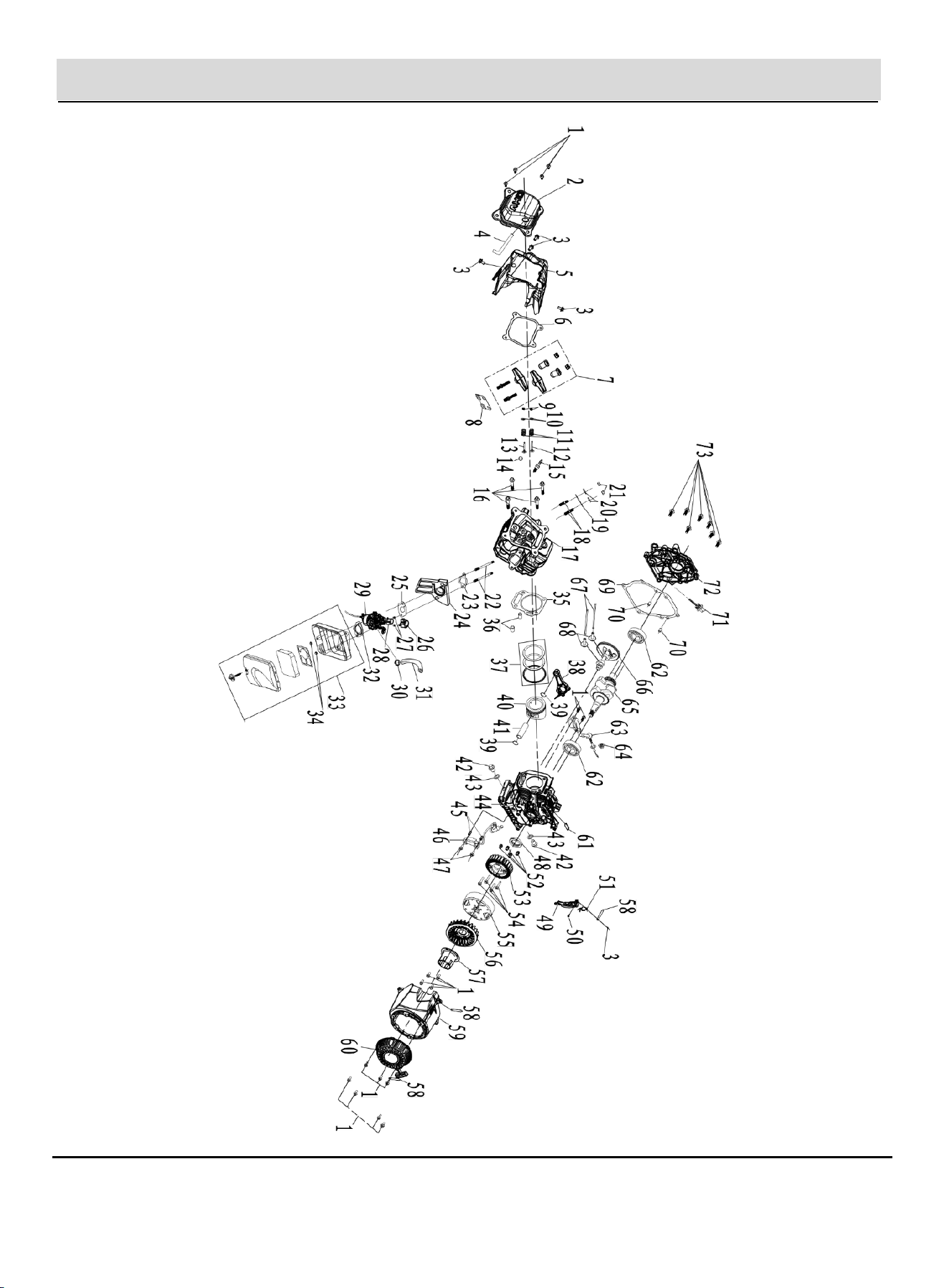
Exploded View-Engine

5
Items
Parts No.
Description
Qty
1
2.63.01.00180
Hexagonal Flange Bolt M6*16
18
2
2.50.01.009050
Cylinder Head Cover
1
3
2.63.01.02494
Hexagonal Flange Bolt M6*16
5
4
2.50.13.000100
Exhaust Pipe
1
5
2.52.06.005719
Windshield
1
6
2.60.09.003800
Cylinder Head Cover Gasket
1
7
2.50.05.002000
Valve Rocker Arm
1
8
2.50.06.000900
Guide Plate
1
9
2.50.09.001300
Valve Adjustment Cap
2
10
2.50.09.000300
Exhaust Valve Spring Retainer
2
11
2.50.09.000100
Valve Spring
2
12
2.50.04.003800
Exhaust Valve
1
13
2.50.03.004000
Intake Valve
1
14
2.50.10.000100
Seal Guide
1
15
2.53.06.000500
Spark Plug
1
16
2.63.01.03750
Hexagonal Flange Bolt M8*60
4
17
2.50.02.009025
Cylinder Head
1
18
2.63.01.02545
Exhaust Stud Bolt M8*34
2
19
2.60.03.000200
Exhaust Gasket
1
20
2.63.01.01705
Spring Washer Φ8
2
21
2.63.01.00287
M8 Hex Nut
2
22
2.63.01.04196
Intake Stud Bolt M6*95
2
23
2.60.02.003400
Air Intake Gasket
1
24
2.55.02.003800
Carburetor Link Block
1
25
2.60.04.000200
Carburetor Spacer
1
26
2.56.03.069080
Stepper Motor Cover
1
27
2.63.01.00832-1
Cross Recess Pan Head Screw M3*8
2
28
2.56.03.051300
Stepping Motor
1
29
2.55.01.049175
Carburetor
1
30
2.62.02.127006
Leaf Spring Clamp Φ12-Φ20
1
31
2.55.11.007622
LPG Inlet Pipe
1
32
2.60.05.000200
Air Filter Spacer
1
33
2.50.11.031102
Air Filter
1
34
2.63.01.00291
Hexagonal Flange Bolt M6
2
35
2.60.08.006700
Cylinder Sealing Gasket
1
36
2.63.01.00406
Locating Pin 10*16
2
37
2.51.11.005100
Piston Ring Set
1
38
2.51.12.006100
Connecting Rod Assy
1
Parts List-Engine

6
39
2.51.10.000100
Clip Piston Pin
2
40
2.51.08.005400
Piston
2
41
2.51.09.000100
Piston Pin
1
42
2.63.01.01754
Drain Plug Bolt, M10*15*1.25
2
43
2.63.01.00497
Aluminum Washer, 10*15*2mm
2
44
2.51.01.030009
Crankcase
1
45
2.62.02.127167
Ignitor Bushing
2
46
2.53.02.009669
Igniter
1
47
2.63.01.02017
Hexagonal Flange Bolt M6*45
2
48
2.51.17.000100
Oil Seal
1
49
2.52.07.006400
Undercover
1
50
2.63.01.01750
Hexagonal Flange Bolt /M6*20
1
51
2.51.04.002900
One-Way Valve
1
52
2.63.01.00329
Locating Pin
2
53
2.80.04.000147
Stator
1
54
2.63.01.02547
Hexagonal Flange Bolt /M6*60
4
55
2.56.03.069030
Rotor
1
56
2.52.04.003900
Cooling Fan
1
57
2.52.03.005033
Starting Cup
1
58
2.62.01.003000
Wire Clips
3
59
2.52.01.210015
Windshield
1
60
2.52.01.210048-6
Starter Recoil Assembly
1
61
2.62.01.018606
Cabinet Plug Block
1
62
2.67.01.000346
Deep Groove Ball Bearing
2
63
2.51.04.000100
Oil Level Sensor
1
64
2.63.01.00299
Hexagonal Flange Nut /M14*1.5
1
65
2.51.15.070800-1
Crankshaft
1
66
2.51.16.007600
Camshaft
1
67
2.50.07.002500
Valve Push Rod
2
68
2.50.08.000200
Poles
2
69
2.60.01.005700
Valve Tappet
1
70
2.63.01.00404
Locating Pin/8*14
2
71
2.51.06.000400
Dipstick
1
72
2.51.05.011034
Crankcase Cover
1
73
2.63.01.04012
Hexagonal Flange Bolt /M8*32
7