
TABLE OF CONTENTS
Introduction. ................................................................................................................................................. 3
Parts Ordering / Customer Service. ...................................................................................................... 3
Product Specifications. ....................................................................................................................... 3
Safety Rules ................................................................................................................................................. 4
Safety Symbols.................................................................................................................................. 4
Safety Instructions .............................................................................................................................. 4
Features ....................................................................................................................................................... 7
Assembly ..................................................................................................................................................... 9
Unpacking
................................................................................................................................................
9
Packing List ........................................................................................................................................ 9
Attaching Wheels .............................................................................................................................. 10
Adding Oil/Checking engine oil ........................................................................................................... 11
Adding Fuel. ...................................................................................................................................... 12
Connecting Generator to a Building Electrical System............................................................................ 12
Operation .................................................................................................................................................... 13
Grounding the Generator. ................................................................................................................... 13
How to Start Engine. .......................................................................................................................... 13
How to Stop Engine. .......................................................................................................................... 14
Receptacles and Extension Cords. ..................................................................................................... 15
Don’t Overload Generator. ................................................................................................................. 16
Wattage Reference Guide. ................................................................................................................. 17
Cold Weather Operation. .................................................................................................................... 18
Maintenance ................................................................................................................................................ 19
Maintenance Schedule ...................................................................................................................... 19
Changing Oil .................................................................................................................................... 20
Engine Maintenance .......................................................................................................................... 21
Maintaining Fuel Valve. ..................................................................................................................... 22
How to Store .................................................................................................................................... 23
Troubleshooting......................................................................................................................................... 24
Diagrams ................................................................................................................................................... 25
INTRODUCTION
3
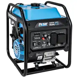
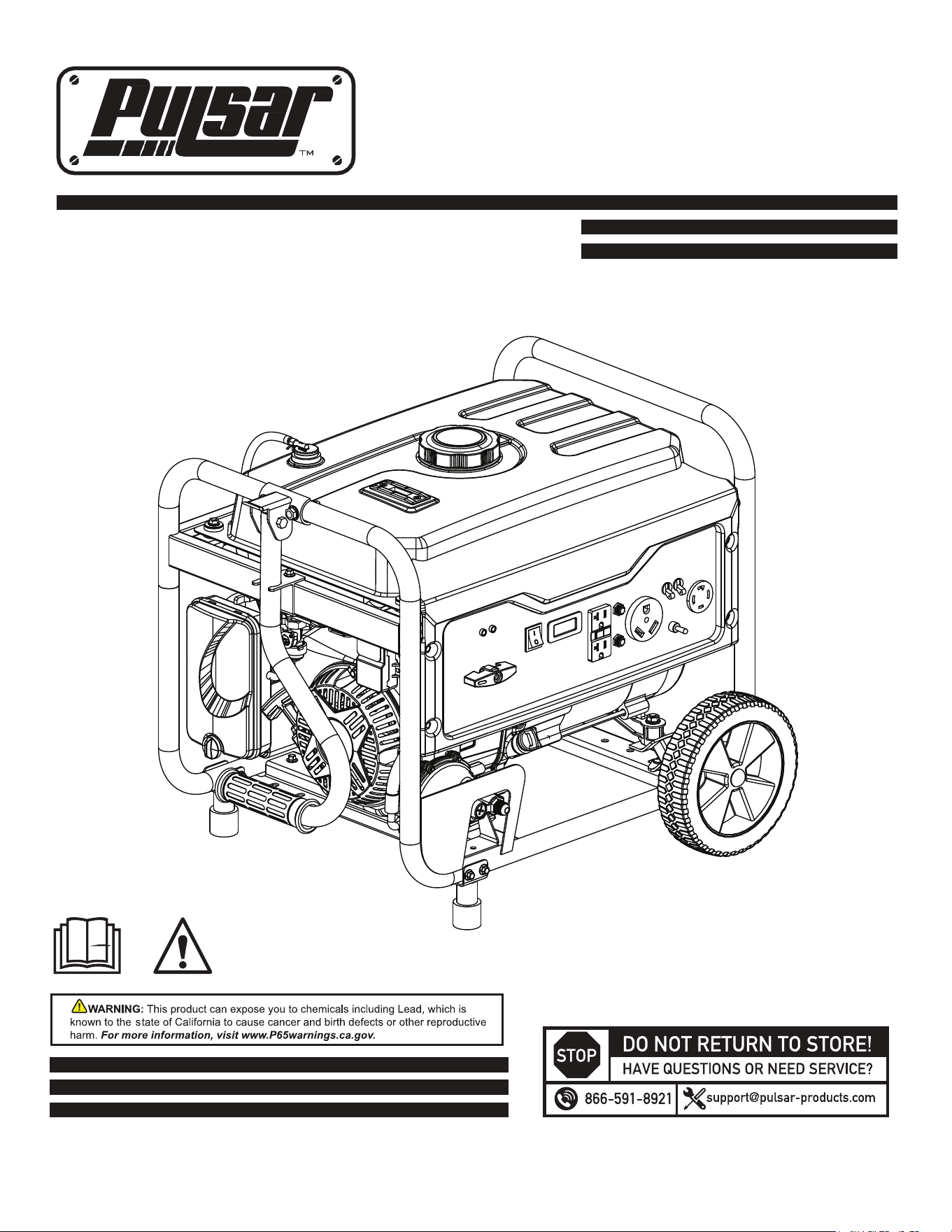
Thank you for purchasing this superior quality portable generator from Pulsar Products Inc. When operating and
maintaining this product as instructed in this manual, your generator will give you many years of reliable service.
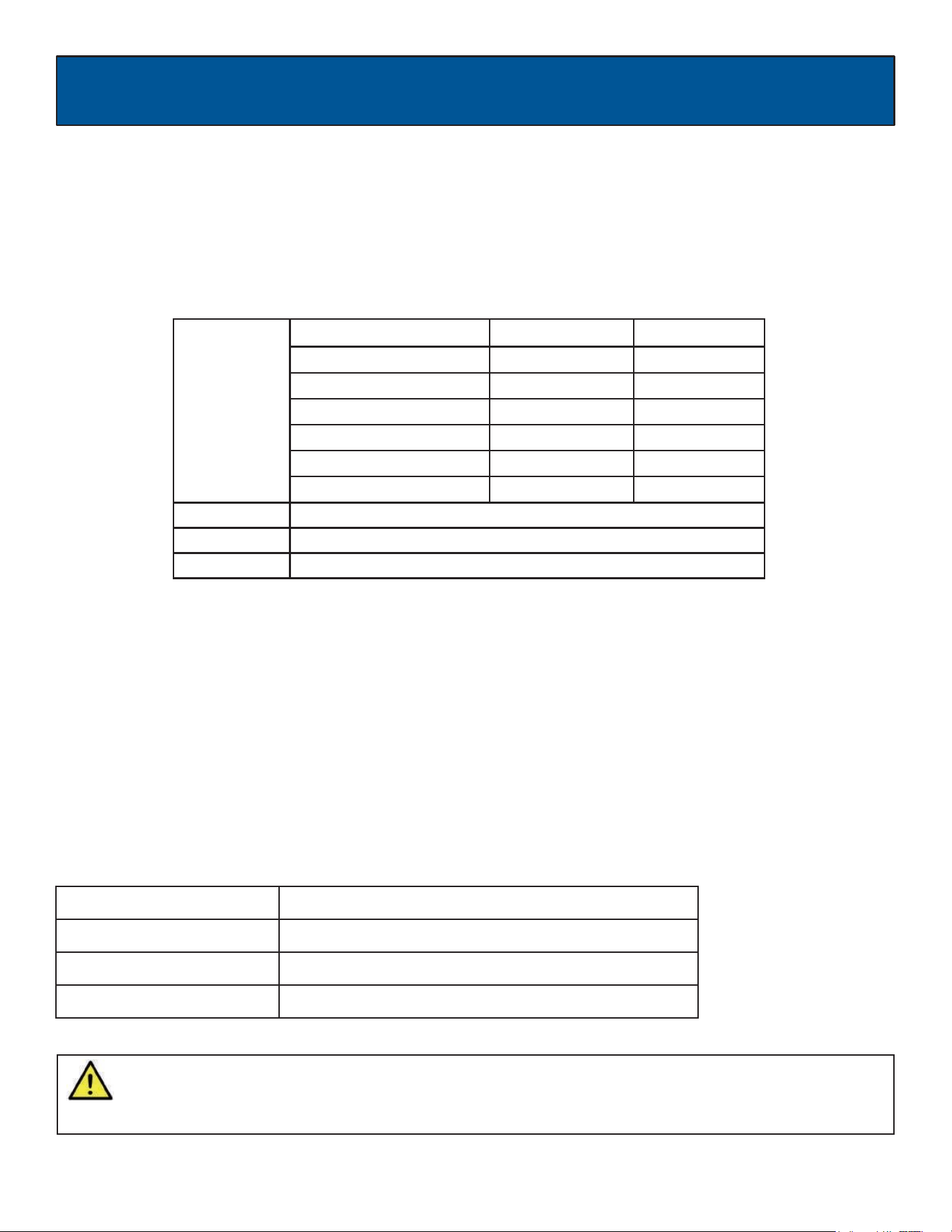
Product Specifications:
This generator is an engine-driven, revolving field, alternating current (AC) portable generator. It is designed to
supply electrical power to operate tools, appliances, camping equipment, lighting, or serve as a backup power
source during power outages.
The emissions control system for this generator is compliant with all standards set by the US EPA.
How to contact us:
To order parts, receive warranty assistance, or other services inquiries, you can contact us via our website at
www.pulsar-products.com or write to us at:
PULSAR PRODUCTS, INC
5721 E. SANTA ANA ST.
ONTARIO, CA 91761
866-591-8921
Record the following information bellow for service or warranty assistance.
Date of Purchase:
Model Number:
Item Number:
Serial Number:
SAVE THIS MANUAL FOR FUTURE REFERENCE
This manual contains important information regarding safety, operation, and maintenance.
AC Output
GAS
LPG
Rated Wattage
4250W (4.25kW)
3850W (3.85kW)
Rated Voltage
120V/240V
120V/240V
Rated Frequency
60Hz
60Hz
Rated Ampere
35.4A / 17.7A
31.6A / 15.8A
Rated Output
4.25kVA
3.85kVA
Maximum Output
5.25kVA
4.75kVA
Engine
224cc OHV, 4 Stroke, Air Cooled
Engine Oil
10W30 - 20oz (0.6L)
Fuel Tank
4.0 Gal (15L) Unleaded Gasoline
4
SAFETY RULES
WARNING!
CAUTION!
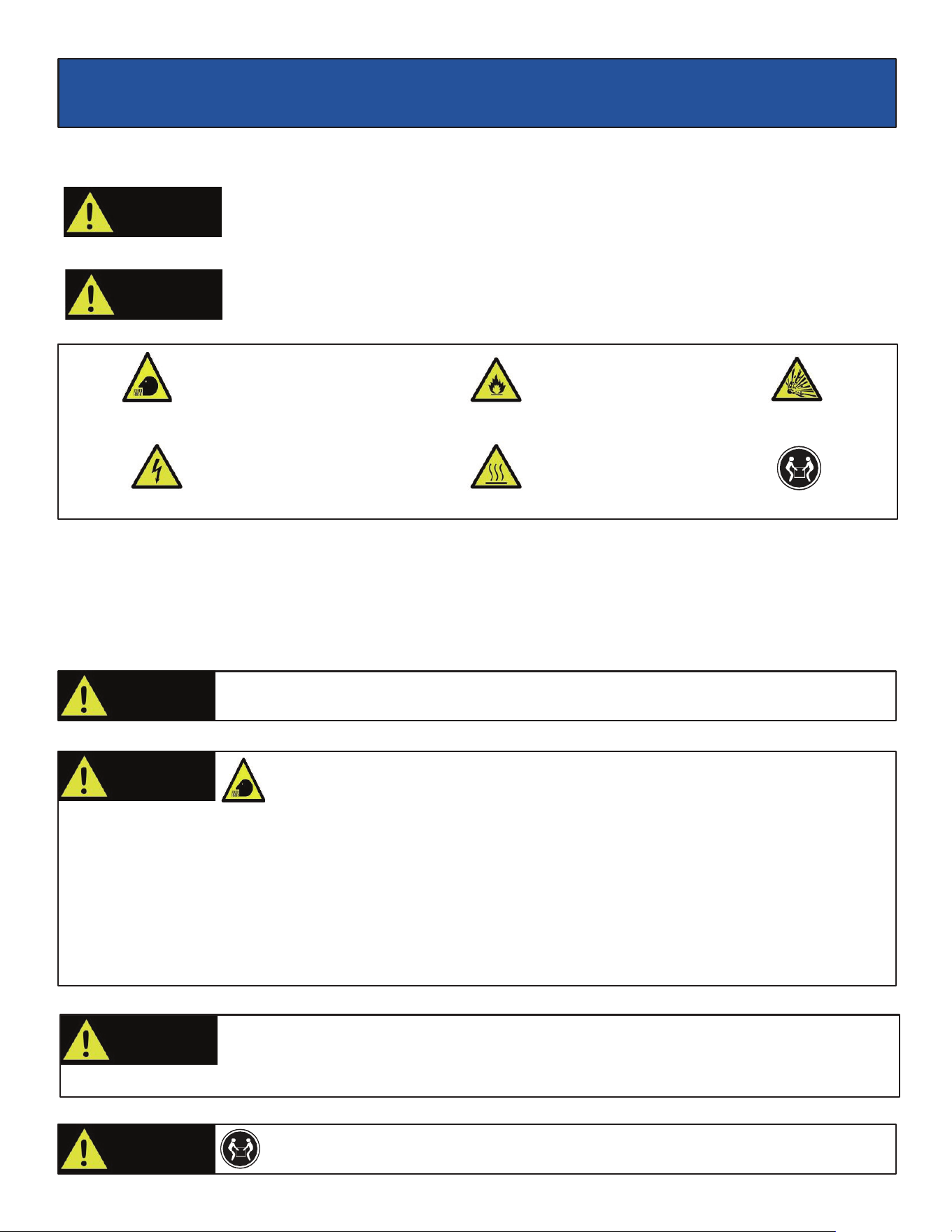
Safety Symbols
Indicates a potentially hazardous situation which could result in serious injury or death if not
avoided.
Indicates a potentially hazardous situation which could result in damage to equipment or
property.
Safety Instructions
The manufacturer cannot anticipate every possible hazardous circumstance that the user may encounter. Therefore, the
warnings in this manual, on tags, and on affixed decals are not all-inclusive. To avoid accidents, the user must understand
and follow all manual instructions and use good common sense.
WARNING!
To reduce the risk of serious injury, avoid attempting to lift the generator alone.
WARNING!
Engine exhaust contains chemicals that lead to cause cancer and birth defects.
•
Always wash hands after handling generator.
WARNING!
Do not operate indoors or in a confined space that prevents
dangerous carbon monoxide gas from dissipating.
•
Using a generator indoors CAN KILL YOU IN MINUTES!
•
Carbon monoxide gas is a poisonous, odorless gas that can cause headache, confusion, fatigue, nausea, fainting,
sickness, seizures, or death. If you start to experience any of these symptoms, IMMEDIATELY get fresh air and seek
medical attention.
•
Never use indoors, in a covered area, or in a confined space, even if doors and windows are open.
•
Install a battery-operated carbon monoxide alarm near bedrooms.
•
Keep exhaust from this unit from entering a confined area through windows, doors, vents, or other openings.
•
When working in areas where vapors could be inhaled, use a respirator rated for carbon monoxide protection.
WARNING!
Read and understand this manual in its entirety before operating this generator. Improper
use of this generator could result in serious injury or death.
Toxic Fumes
Risk of fire
Risk of explosion
Risk of electric shock
Hot surface
Lifting hazard
5
SAFETY RULES
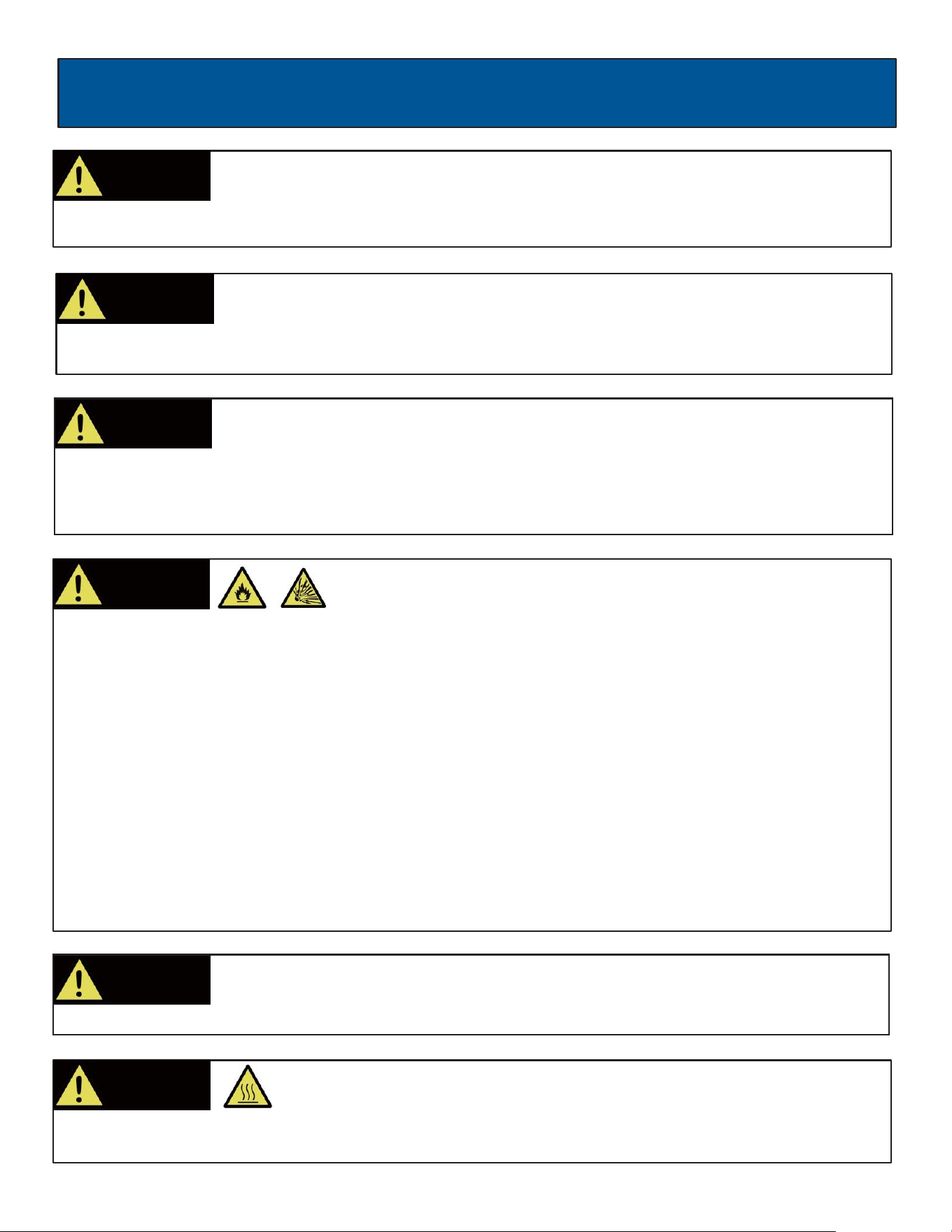
WARNING!
Avoid contacting hot areas of this unit.
•
Use caution around the muffler, cylinder, and other engine parts as they can be extremely hot.
•
Allow hot components to cool before touching.
Pull cord recoils rapidly and can pull arm towards engine faster than you can let go which
could result in injury.
•
To avoid recoil, pull starter cord slowly until resistance is felt, then pull rapidly.
WARNING!
Keep engine away from flammable objects and other hazardous materials.
•
The fuel and its vapors used to power this unit are highly flammable and could explode resulting in serious injury or
death.
•
Never fill or drain fuel tank indoors.
•
Never overfill fuel tank. If fuel spills, move the unit at least 30 feet away from the spill and wipe up any remaining fuel
on the unit before starting the engine.
•
Never smoke while operating or fueling this unit.
•
Never operate or store this unit near an open flame, heat, or any other ignition source.
•
Generator should be far away from buildings or other equipment during operation.
•
Keep engine free of grass, leaves, or grease and other flammable debris.
•
When adding or draining fuel, unit should be turned off for at least 2 minutes to cool before removing fuel cap. If unit
has been running, the fuel cap may be under pressure, remove slowly.
•
To keep fuel from spilling, secure unit so it cannot tip while operating or transporting.
•
When transporting unit, disconnect the spark plug wire and make sure the fuel tank is empty with the fuel shutoff valve
turned to the off position.
WARNING!
Starter recoil and other moving parts can catch on clothing, jewelry, and hair.
•
Do not wear loose clothing or loose gloves.
•
Remove jewelry or anything else that could be caught in moving parts.
•
Tie back hair, or wear protective head covering to contain long hair.
WARNING!
Never start or stop engine with electrical devices plugged in to the receptacles. Failure to do
so could damage the generator and / or connected electrical devices.
•
Always start the engine and let it stabilize before connecting any electrical devices.
•
Disconnect all electrical devices before stopping the engine.
WARNING!
Never exceed generator’s wattage / amperage capacity. This could damage the generator
and / or connected electrical devices.
•
Check operating voltage and frequency of all electrical devices prior to plugging in to generator.
6
SAFETY RULES
PROP 65 WARNING: This product contains chemicals known to the state of California to cause cancer and birth defects or
other reproductive harm.
WARNING!
Never operate this unit if there are any broken or missing parts and only use Pulsar
replacement parts specifically designed for this unit.
•
Improper treatment of generator can damage the unit and shorten its life.
•
Always repair this unit as specified in this manual. If you have any questions, contact your dealer or consult a
qualified service center.
•
Shut generator off if electrical output is missing, unit vibrates excessively or begins to smoke, spark or emit flames.
WARNING!
Only use this unit as intended or serious injury or death could result.
•
Do not bypass any safety device. Moving parts are covered with guards. Make sure all protective covers are in place.
•
Never transport or make adjust this unit while it is running.
•
Never insert objects through cooling slots.
WARNING!
Never modify this unit in any way or modify governed speed.
•
Increasing governed speed is dangerous which can result in personal injury and / or damaged equipment.
•
Decreasing governed speed adds an excessive load and can damage equipment.
•
Only when operating at the preset governed speed this generator will supply the correct rated frequency and
voltage.
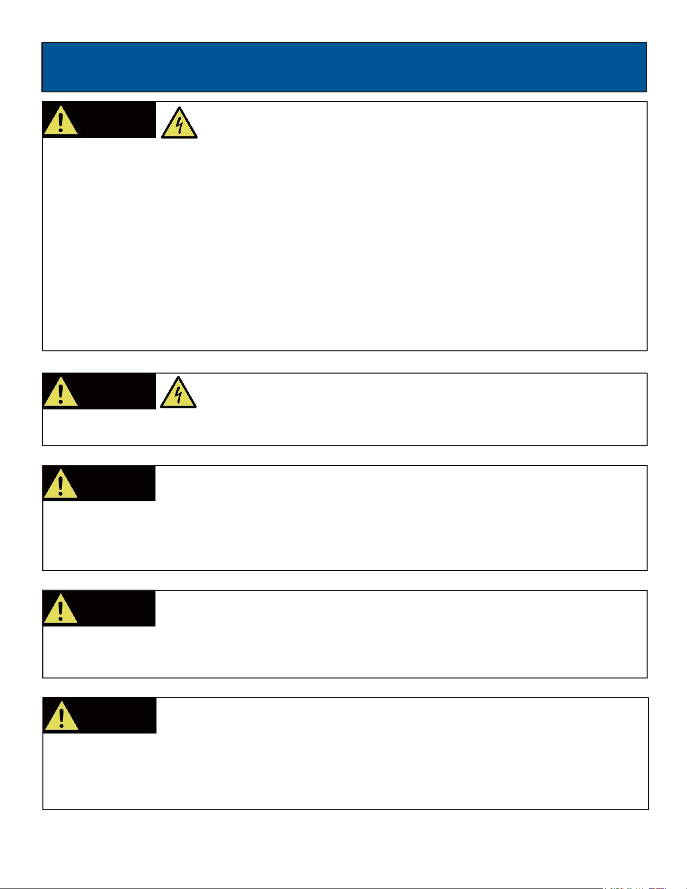
WARNING!
Generator must be properly grounded to prevent electrocution.
•
Only operate generator on a level surface.
•
If connected to a structure, connect the ground terminal on the frame to an appropriate eground
source.
WARNING!
This generator produces high voltage which could result in burns or
electrocution causing serious injury or death.
•
Never handle the generator, electrical devices, or any cord while standing in water, while barefoot, or when hands or
feet are wet.
•
Always keep the generator dry. Never operate generator in rain or under wet conditions.
•
Use a ground fault circuit interrupter (GFCI) in a damp or highly conductive area, such as metal decking
or steel work.
•
Never plug electrical devices into generator having frayed, worn, or bare wires. Never touch bare wires or contact
receptacles.
•
Never permit a child or unqualified person to operate generator. Always keep children a minimum of 10 feet away
from the generator.
•
If using the generator for backup power, notify the utility company.
•
If connecting generator to a building’s electrical system for standby power, you must use a qualified electrician to
install a transfer switch. Failure to isolate the generator from the power utility could result in serious injury or death to
electric
utility workers.
7
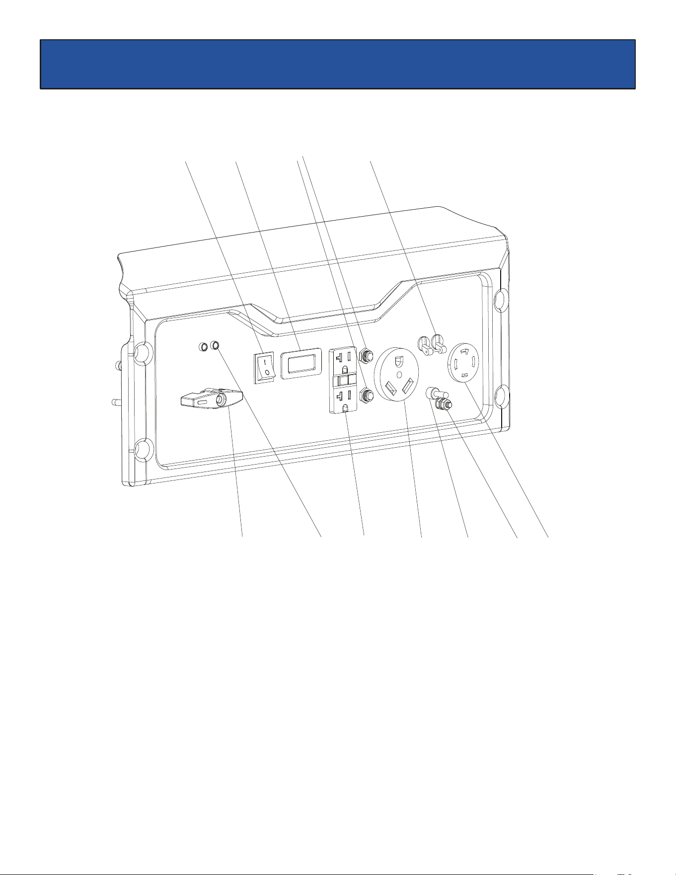
FEATURES
A - ON/OFF Switch
B -
Status Display
C -
Circuit Breakers
D - Main Circuit Breaker
E - Fuel Selector Switch
F - CO Sensor Light
G - Two 120 V GFCI Outlets (NEMA 5-20R)
H - TT-30 RV Outlet
I - Voltage Selector
J - Ground Terminal
K - 120/240 Volt AC, 30 Amp Twist-Lock Outlet (NEMA L14-30)
A
F G H I J
B
C D
E K
8
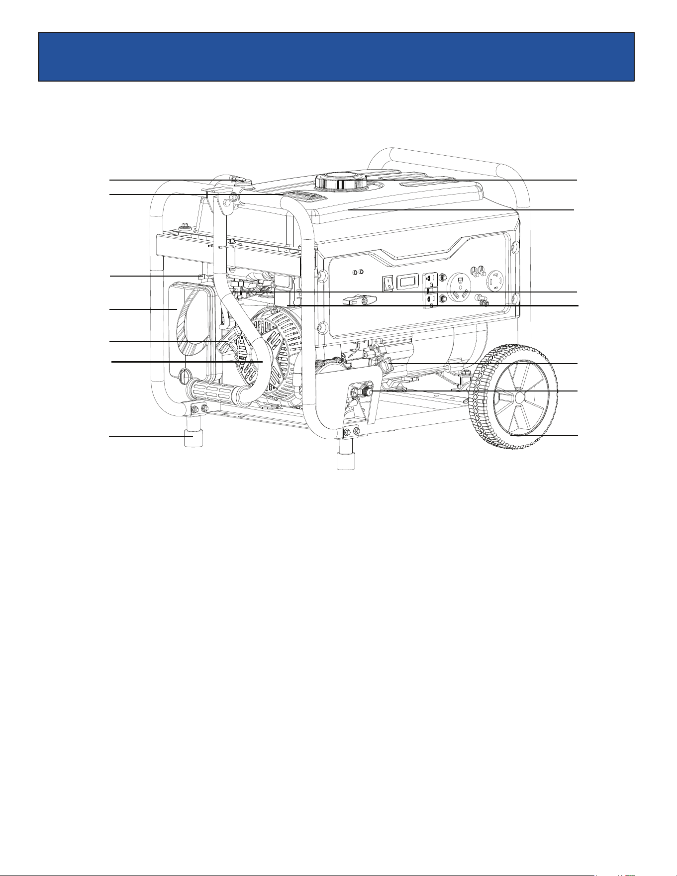
FEATURES
S
L
T
M
N
O
U
P
Q
V
W
X
R
L - Tank Vapor Valve
M - Fuel Gauge
N - Choke Lever
O - Air Filter Housing
P - Pull Start
Q - Handle
R - Support Foot
S - Fuel Cap
T - Fuel Tank
U - Fuel Valve
V - CO sensor
W - Oil Fill (Dipstick)
X - Propane Inlet
Y - No Flat Wheels
Y
9
ASSEMBLY
Unpacking
1.
Place box on a level surface.
2.
Remove all items from box except the generator. Make sure all items listed on the packing list are included and
undamaged
3.
Cut-down the sides of the box being careful to avoid touching the generator.
4.
Leave generator on box to install wheel assemblies.
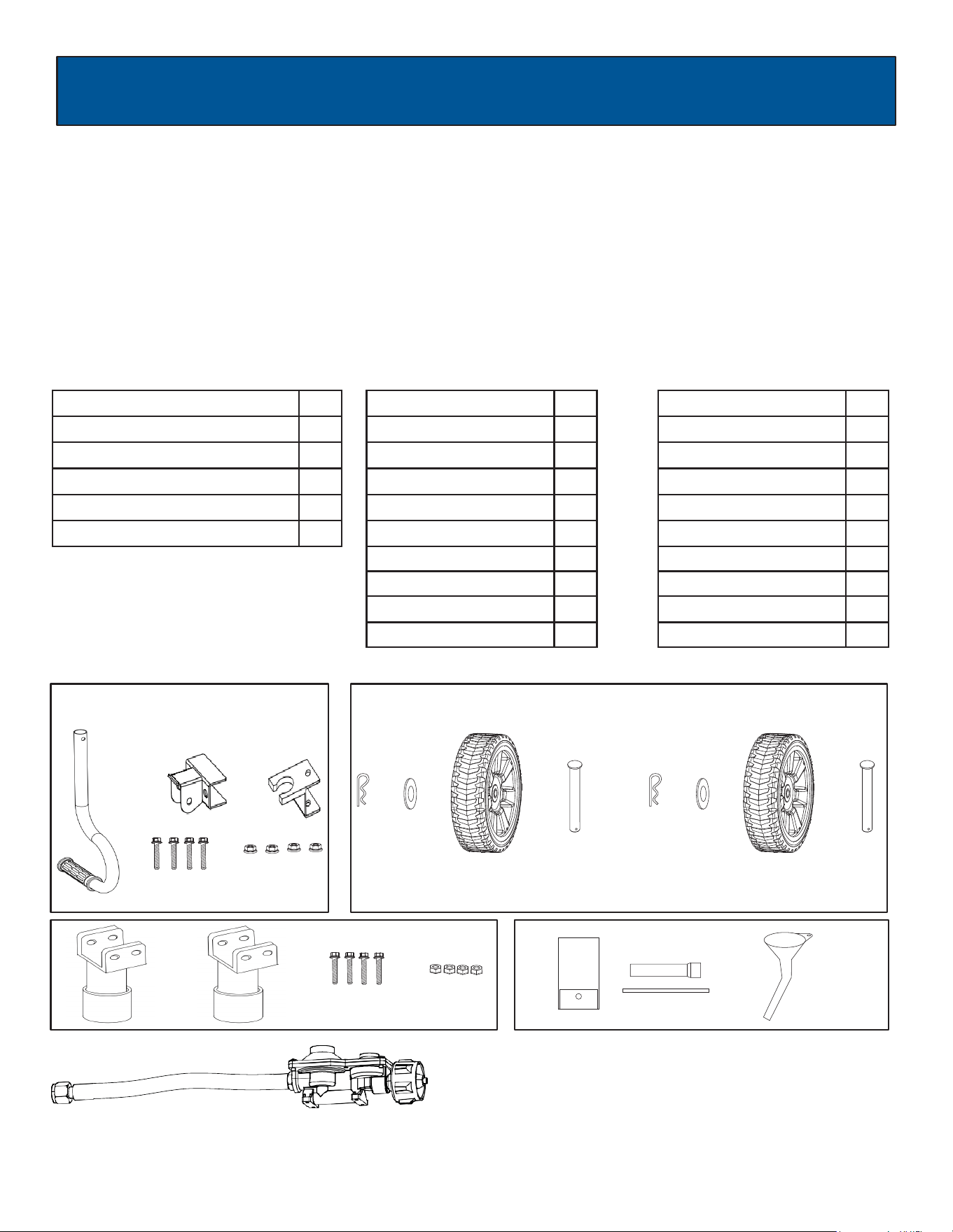
Packing List
Check all loose parts to the following list. Contact your dealer if any loose parts are not included.
Description Qty
Handle
Screw
Nut
1
4
4
Wheels
2
Hair pin
2
Axles
2
Description Qty
Generator
1
Operator’s manual
1
Toolkit
Spark Plug Wrench
1
1
Washer
2
Description Qty
Supporting Leg
Screw(M6)
Nut(M6)
2
4
4
Funnel
+ +
+
+ ++ +
( )
++ +
+
Handle Assembly Wheel Assembly
Foot Assembly
+
+
+
Handle Bracket 1
1Handle Clip
Two stage regulator
1
ASSEMBLY
10
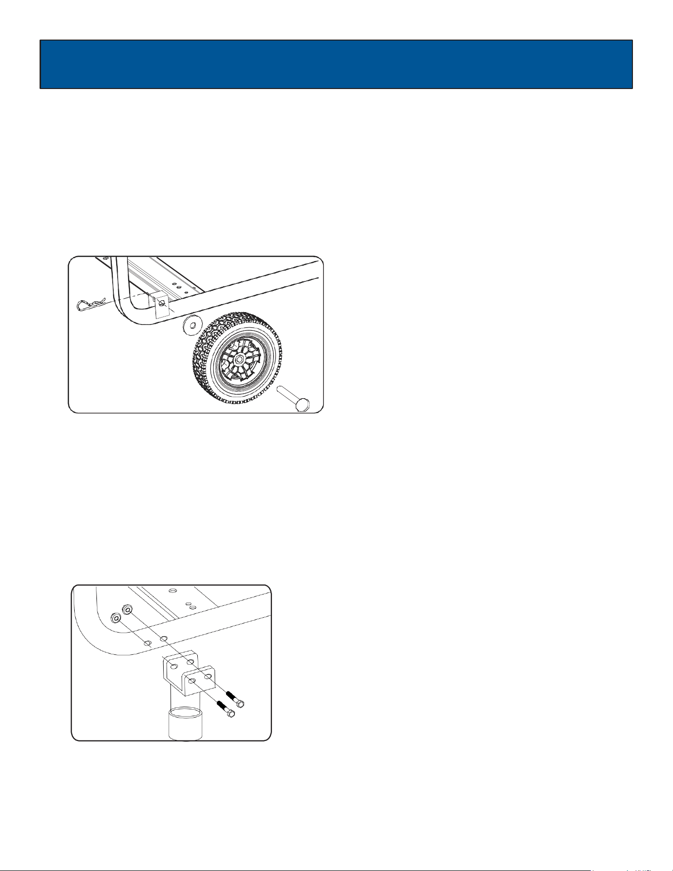
Attaching Wheels (See fig 1)
•
Parts needed - 2 wheels, 2 axles, 2 washers and 2 hair pins.
•
Raise or tilt generator so you can slide the wheel axle pin into the wheel, the washer, and the wheel mounting hole
located on the side of the frame.
•
Secure the wheel assembly by inserting a hair pin through hole at the end of the wheel axle clevis pin and pressing until
it locks into place.
•
Repeat process on the other side of the generator to install the second wheel.
Fig 1
Installing Support Leg (See fig 2)
•
Parts needed - Support Leg (2) & M8 screw (2) and 2 nuts.
•
Raise the front end of the generator high enough to gain access to the bottom of the frame. Securely position
props underneath to support.
•
Line up holes on the support leg bracket to the holes on the front of the generator frame.
•
Attach the support leg using M8 screws (2) and nuts.
Fig 2
ASSEMBLY
11
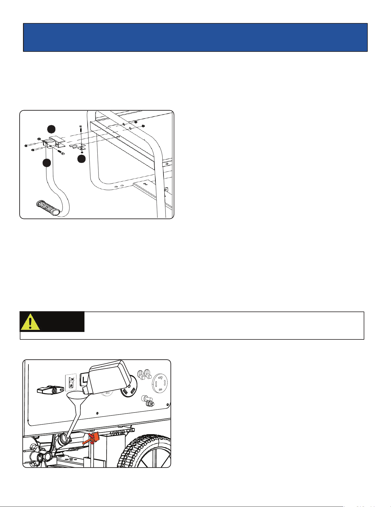
Handle Assembly (See fig 3)
1. Install handle lock holder by inserting bolt and lock nut. (fig 3)
2. Install handle bracket to frame with 2 bolts and lock nuts as shown on illustration.
3. Set handle in the bracket aligning the holes and insert handle bolt and lock nut.
Fig 3
Adding / Checking Engine Oil (See fig 4)
• Place generator on a level surface.
• Clean area around oil fill.
• Remove oil fill cap and wipe dipstick clean.
• Insert, but do not tighten dipstick into filler neck. Remove dipstick and verify oil level is within safe operating range.
• Add recommended engine oil
as necessary. (See Add Engine Oil.)
• Install oil fill cap/dipstick and hand-tighten.
Fig 4
CAUTION!
You must add oil before first operating this generator. Always check oil level before each
operation.
2
3
1
ASSEMBLY
12
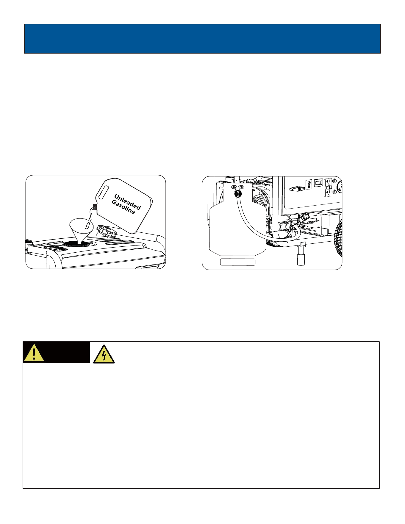
Adding Fuel (See fig 5)
•
Set generator outdoors in a well-ventilated area, away from structures and people.
•
Slowly remove fuel cap.
•
Insert a funnel into the fuel tank and carefully pour gasoline into the tank until fuel level reaches 1 ½ inches below the
top of the neck. Be careful not to overfill the tank to allow space for fuel expansion.
Connecting Propane Tank to Generator (See fig 6)
•
Connect propane hose to generator propane inlet located at the bottom left corner of the generator.
•
Then connect other end to the propane tank connection. (Propane tank not included)
Fig 5 Fig 6
Connecting Generator to a Building Electrical System
•
If connecting generator to a building electrical system for standby power, you must use a qualified electrician to install a
transfer switch. The power from the generator must be isolated from the utility power source. The connection must
comply with all electrical codes and applicable laws.
WARNING!
This generator produces high voltage which could result in burn or
electrocution causing serious injury or death.
•
Never handle the generator, electrical devices, or any cord while standing in water, while barefoot, or when hands or
feet are wet.
•
Always keep the generator dry. Never store or operate generator in rain or under wet conditions.
•
Use a ground fault circuit interrupter (GFCI) in a damp or highly conductive area, such as metal decking or steel work.
•
Never plug electronic devices into generator having frayed, worn, or bare wires. Never touch bare wires or contact
receptacles.
•
Never permit a child or unqualified person to operate generator. Always keep children a minimum of 10 feet away
from the generator.
•
If using the generator for backup power, notify the utility company.
•
If connecting generator to a building’s electrical system for standby power, you must use a qualified electrician to
install a transfer switch. Failure to isolate the generator from the power utility could result in serious injury or death to
electric utility workers.
13
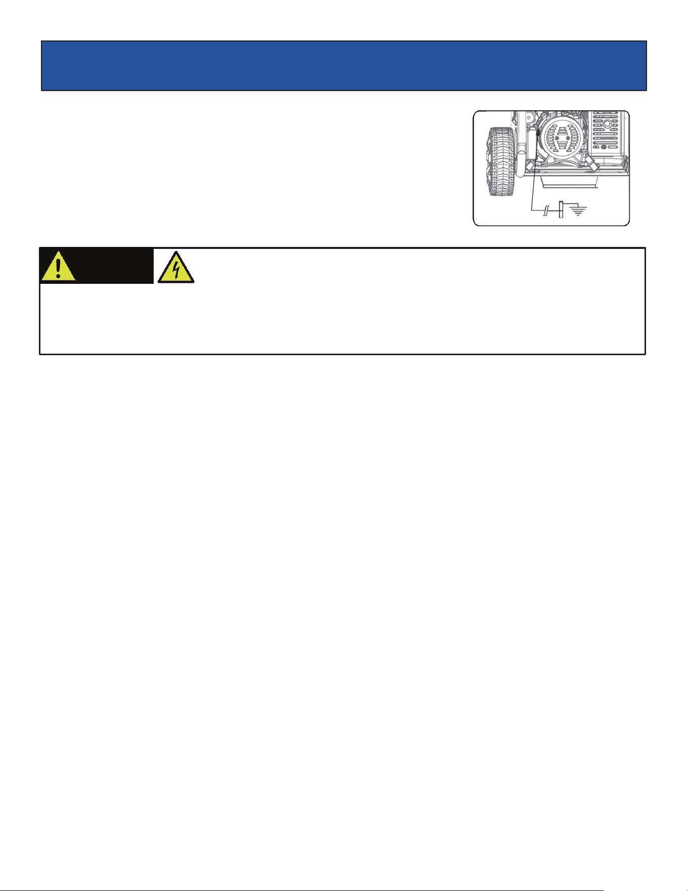
Fig 7
Grounding the Generator (See fig 7)
The portable generator is equipped with a terminal for the connection of a ground
electrode conductor where a grounding electrode system is required by NEC Article
250.34(A). The equipment grounding conductor terminals of the generator receptacles
are bonded to the generator frame. Where the generator supplies power to cord and
plug connected equipment, like power tools, the frame of the generator is not required
by the NEC to be connected to an earthen ground electrode. The generator neutral
conductor is bonded
to the generator frame in accordance with NEC Article 250.34(C)
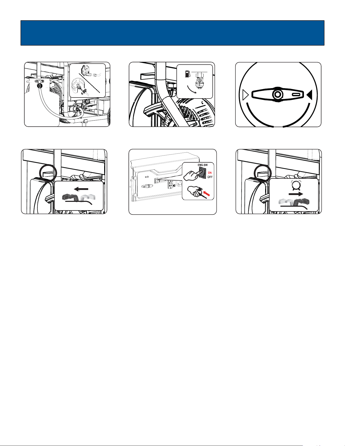
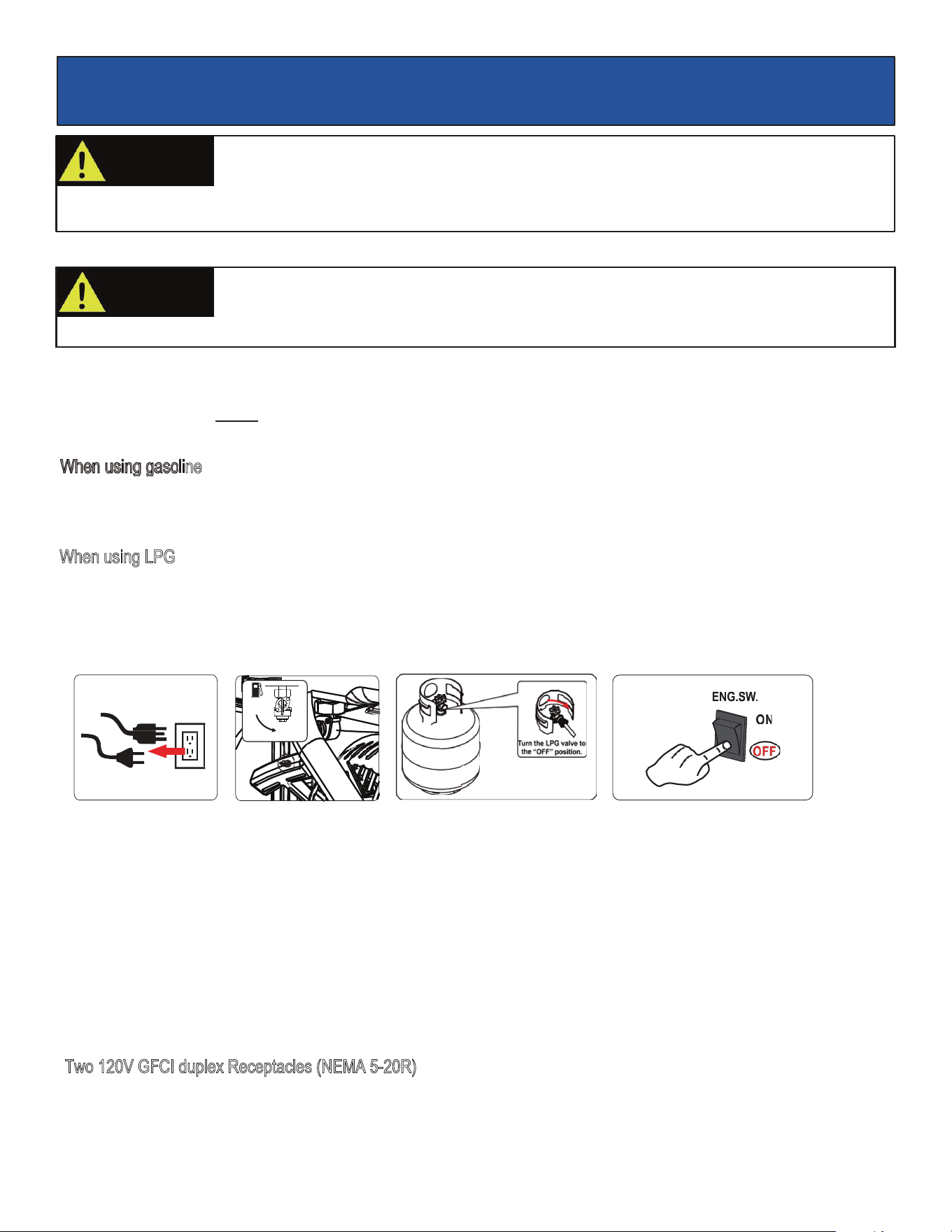
How to Start Engine (See fig 8-13)
•
Place generator on a level surface. All electrical loads MUST be disconnected from generator.
When using gasoline
•
Turn fuel valve to the “ON” position. (See fig 9)
•
Turn the fuel selector to “GAS” position (See fig 10)
•
Slide the choke lever to the “Choke” position. (See fig 11) SKIP THIS IF THE ENGINE IS WARM OR HOT.
•
To start, turn the engine ON/OFF switch to the “ON” position. Pull the recoil starter grip slowly until resistance is
felt, then pull rap
idly. (See fig 12)
•
Let engine run for several seconds and then gradually, as engine warms up, slide the choke lever towards the “RUN”
position until the choke is fully at the “RUN” position. (See fig 13)
When using LPG
•
Connect the propane hose to the propane tank and generator; Open the valve of LPG bottle (See fig 8)
•
Turn the fuel selector to “Propane” position (See fig 10)
•
Slide the choke lever to the “Choke” position. (See fig 11) SKIP THIS IF THE ENGINE IS WARM OR HOT.
•
To start, turn the engine ON/OFF switch to the “ON” position. Pull the recoil starter grip slowly until resistance is
felt,
then pull rapidly. (See fig 12)
•
Let engine run for several seconds and then gradually, as engine warms up, slide the choke lever towards the “RUN”
position until the choke is fully at the “RUN” position. (See fig 13)
WARNING!
Generator must be properly grounded to prevent electrocution.
•
When operated as a portable generator, keep out of rain and away from standing water
•
When generator is connected to a building or structure, an additional ground wire must be installed between
the threaded grounding lug and a suitable earthen ground
OPERATION
14
OPERATION
Fig 8
Fig 9
Fig 10
Fig 11
SKIP THIS IF THE ENGINE IS
WARM OR HOT.
Fig 12 Recoil Start
Fig 13
WAIT
5sec
CHOKE
RUN
CHOKE LEVER
CHOKE RUN
CHOKE LEVER
GAS
PROPANE
OFF
ON
15
OPERATION
How to Stop Engine (See fig 14-17))
•
All electrical loads MUST be disconnected from the generator. Never start or stop the engine with electrical devices
plugged-in to the receptacles. (See fig 14)
When using gasoline
1.
Turn the engine ON/OFF switch to the “OFF” position. (See fig 17)
2. Turn the fuel valve lever back to the OFF position. (See fig 15)
When using LPG
1.
Turn the engine ON/OFF switch to the “OFF” position. (See fig 17)
2.
Close valve on LPG bottle. (See fig 16)
Fig 14 Fig 15 Fig 16
Fig 17
Receptacles and Extension Cords
Only use high quality, well-insulated, grounded extension cords in good condition with generator receptacles. Follow each
electrical device manufacturer’s power ratin
g recommendation when selecting receptacle and extension cord.
This generator is equipped with the following receptacles:
•
Two 120V GFCI duplex Receptacles (NEMA 5-20R).
•
120 Volt AC, 30 Amp RV receptacle (NEMA TT-30R).
•
120 / 240 Volt AC, 30 Amp twist lock receptacle (NEMA L14-30R).
T
wo 120V GFCI duplex Receptacles (NEMA 5-20R)
•
This receptacle has a 20 Amp push-to reset circuit breaker to protect against overload.
•
Each socket is rated to operate 120 Volt, AC, single phase, 60Hz loads requiring up to 2400 watts (2.4 kW) at 20 Amps.
•
Use extension cords having a minimum rating of 125 Volts AC, 20 Amps.
Pull cord recoils rapidly and can pull arm towards engine faster than you can let go could result in
injury.
•
Pull starter cord slowly until resistance is felt, then pull rapidly.
WARNING!
Never start or stop engine with electrical devices plugged in to the receptacles. Failure to
heed this warning could damage the generator and / or connected electrical devices.
•
Always start the engine and let it stabilize before connecting any electrical devices.
•
Disconnect all electrical devices before stopping the engine.
OFF
ON
OPERATION
16
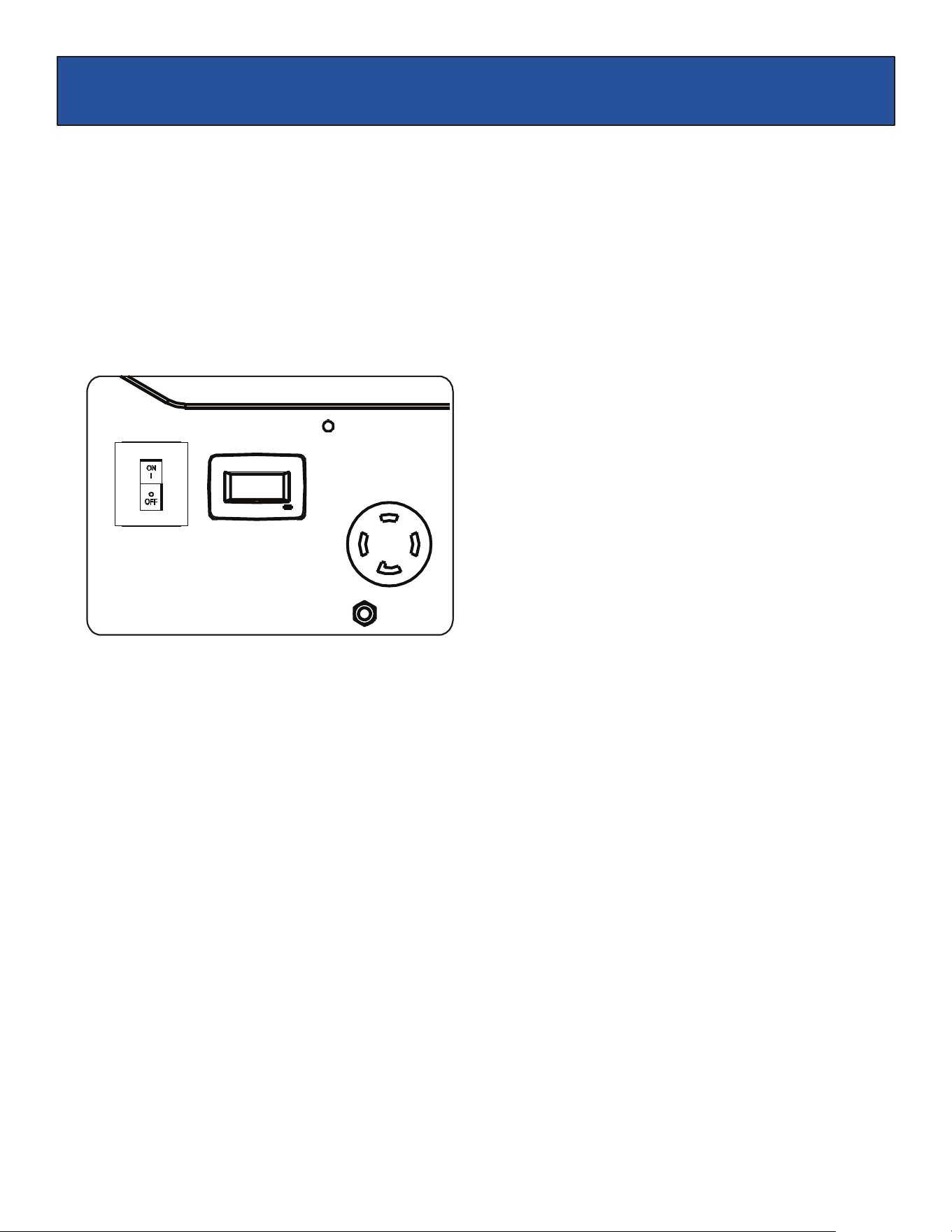
120 / 240 Volt AC, 30 Amp locking receptacle
•
This receptacle has a 30 Amp push-to reset circuit breaker to protect against overload.
•
This receptacle is rated to operate 120 Volt, AC, single phase, 60Hz loads requiring up to 3600 watts (3.6 kW) at 30
Amps. It is also rated to operate 240 Volt AC, single phase, 60Hz loads requiring up to 7,200 watts (7.2 kW).
•
Use a NEMA L14-30 plug with this receptacle.
•
Use a 4-wire cord rated for 240 Volts AC, 30 Amps to the plug. You can use the same 4-wire cord to operate a 120
Volt load.
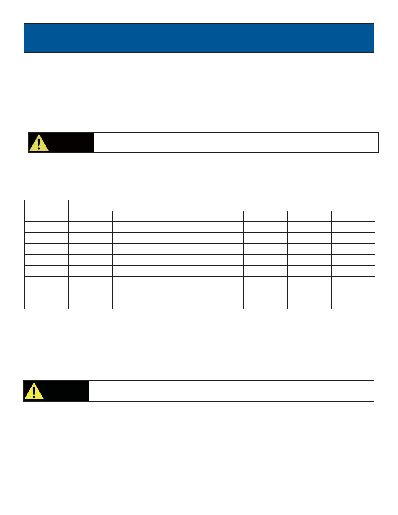
Extension Cord Selection
Refer to the below table to ensure the extension cord used has the capacity to carry the required load. If the size of
the cable is inadequate it can cause a voltage drop and heat buildup, which can damage the electrical device and cord.
Current
(Amps)
Load (Watts)
Maximum Cord Length
120V
240V
#8 Wire
#10 Wire
#12 Wire
#14 Wire
#16 Wire
2.5
300
600
X
1000 ft.
600 ft.
375 ft.
250 ft.
5
600
1200
X
500 ft.
300 ft.
200 ft.
125 ft.
7.5
900
1800
X
350 ft.
200 ft.
125 ft.
100 ft.
10
1200
2400
X
250 ft.
150 ft.
100 ft.
50 ft.
15
1800
3800
X
150 ft.
100 ft.
65 ft.
X
20
2400
4800
175 ft.
125 ft.
75 ft.
X
X
25
3000
6000
150 ft.
100 ft.
X
X
X
30
3600
7200
125 ft.
65 ft.
X
X
X
Moving the Generator
•
Disconnect any electrical devices from generator then switch the generator off.
•
Turn fuel valve to the “OFF” position, then switch OFF the engine On/Off Switch.
•
Use the handle to tilt generator until it balances on wheels. Roll machine to desired location.
•
If the generator must be carried, fold handle to the down position. Never lift or carry generator by
its handle.
Don’t Overload Generator
Make sure you can supply enough rated watts and surge watts for all electrical loads connected to the generator. Rated
watts refer to the power a generator must supply to keep a device running. Surge watts refer to the power a generator
must supply to start an electrical device. This power surge for starting a device usually lasts between 2-3 seconds but
this additional output must be considered when selecting the electrical devices, you plan to attach to the generator. To
prevent overloading the generator, take the following steps:
CAUTION!
This product is heavy and requires several people to lift. Lift and lower with your legs by
b e n d i n g the knees, not your back, to avoid injury.
CAUTION! Do not connect 3-phase loads to generator.

OPERATION
17
Operating voltage and frequency requirement of all electrical equipment should be checked prior to plugging them into this
generator. Damage may result if the equipment is not designed to operate within a +/- 10% voltage variation, and +/- 3 Hz
frequency variation from the generator name plate ratings. To reduce the risk of damage, always have an additional load
plugged into the generator if solid-state equipment (such as television set) is used. A power line conditioner is
recommended for some solid-state applications.
Wattage Reference Guide
(Wattages listed are just approximations. Check electronic device for actual wattage)
WARNING!
Never exceed generator’s wattage / amperage capacity. This could damage the generator
and / or connected electrical devices.
•
Check operating voltage and frequency requirements of all electrical devices prior to plugging in to the generator.
Bathroom
Rated Watts
Surge Watts
Hair Dryer
1250
1250
Curling Iron
1000
1000
Family Room
X-Box or Play Station
40
40
AM/FM Radio
100
100
VCR
100
100
Color TV (27”)
500
500
Home Office
Fax Machine
65
65
Personal Computer (17” Monitor)
800
800
Laser Printer
250
950
Copy Machine
700
800
Power Tools
1000W Quartz Halogen Work Light
1000
1000
Airless Sprayer (⅓ HP)
600
800
Reciprocating Saw
750
950
Circular Saw (7 ¼”)
1400
2300
Miter Saw (10”)
800
1200
Table/Radial Arm Saw
1000
2000
Electric Drill (½ HP, 5.4 Amps)
600
900
Hammer Drill
700
1000
Air Compressor
1600
4500
Other
Home Security System
500
500
Garage Door Opener (⅓ HP)
750
750
Essentials
Rated Watts
Surge Watts
75W Light Bulbs
75 each
75 each
18 CU Ft Refrigerator / Freezer
800
2200
Furnace Fan (⅓ HP)
800
2350
Sump Pump (⅓ HP)
1000
2000
Water Pump (⅓ HP)
1000
3000
Heating/Cooling
Dehumidifier
650
800
Table Fan
200
300
Window AC (10k BTU)
1200
3600
Central Air (4 ton)
1500
6000
Electric Blanket
400
400
Space Heater
1800
1800
Kitchen
Blender
300
900
Toaster (2 slice)
1000
1000
Coffee Maker
1500
1500
Electric Range (1 element)
1500
1500
Dishwasher
1500
2000
Electric Oven
3500
3500
Electric Water Heater
4000
4000
Laundry Room
Iron
1200
1200
Washing Machine
1150
2400
Gas Clothes Dryer
700
1500
Electric Clothes Dryer
5400
6750
OPERATION
18
Use this meter along with the manual to determine when and what type of service on the unit is needed. The display
will show the word “P25” at the first 25 hours of operation and again at every 100 hours of operation after.
Power Management
•
Start engine without anything connected to generator.
•
When engine has stabilized, plug in and turn on first load. It is strongly recommended to plug in devices with the largest
load first and the smallest load last to help prevent overloading the generator.
•
Allow generator output to stabilize (engine and attached devices run evenly) before plugging in the next load.
Fig 18
Cold Weather Operation
Under humid conditions where temperatures drop to 40ºF (4ºC) the carburetor and/or crankcase breather system may
begin to freeze. To prevent cold weather performance issues, take the following steps:
1.
Replace any old fuel with clean, fresh fuel.
2.
Use SAE30 or SAE 10W-30 engine oil. Check oil daily or after every 8 hours of use.
3.
Ensure generator is serviced according to the maintenance schedule under “Maintenance” section of the manual.
4.
Shelter unit from elements.
Status Display (See Fig 18)
19
MAINTENANCE
Pre-Operation Steps
Before starting the engine, perform the following pre-operation steps:
•
Check the level of the engine oil and the fuel tank level.
•
Make sure the air filter is clean.
•
Remove any debris that has collected on the generator and around the muffler and controls. Use a vacuum cleaner to
pick up loose debris. If dirt is caked on, use a soft bristle brush.
•
Inspect the work area for hazards.
After Each Use
Follow the following procedure after each use:
•
Close the Fuel Valve
•
Switch OFF the engine
•
Wait for the generator to become cool to the touch
•
Store unit in a clean and dry area.
Maintenance Schedule
WARNING!
Before inspecting or servicing this machine, make sure the engine is off and no parts are
moving. Disconnect the spark plug wire and move it away from the spark plug.
Regular maintenance will extend the life of this generator and improve its performance. The warranty does not cover
damage resulting from operator negligence, misuse, or abuse. To receive full value from the warranty, operator must
maintain the generator as instructed in this manual, including proper storage.
After First 5 Hours Change Oil
After 8 Hours or Daily Clean Debris from Generator and Air Filter area
Check Engine Oil Level
Annually (25 hr Use) Check and Clean Air Cleaner
Inspect Muffler and Spark Arrester
Annually (100 hr Use) Service Spark Plug (Replace with NGK BP6ES, Champion N9YC or equivalent)
Inspect Fuel Valve and Fuel Lines for leaks or damage
Inspect Muffler and Spark Arrester
Check and Clean Air Cleaner Assembly, Replace Air Filter
Clean Cooling System Cylinder Head Fins and Flywheel Fan
Change Engine Oil after the first 25 hours, again at 50 hours; then every 100
hours thereafter.
20
MAINTENANCE
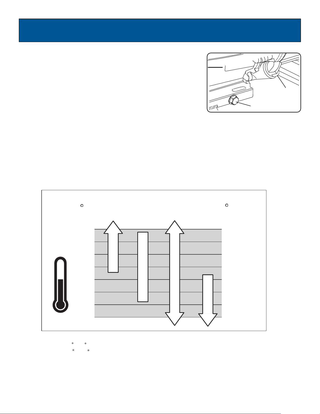
F
104
86
68
50
32
14
-4
-22
*
*
*
C
40
30
20
10
0
-10
-20
-30
Changing Oil (See Fig 19)
•
Run the Generator until the Engine is warm, then shut OFF.
•
Place generator on a level surface.
•
Remove the crankcase dipstick.
•
Place an oil pan underneath the oil drain hole to collect used oil.
•
Remove the oil drain plug and allow oil to drain completely.
•
Reinstall oil drain plug, tighten securely.
•
Carefully add SAE 30 or 10W-30 to empty reservoir until the oil reaches the
threads of the oil fill hole (Crankcase Dipstick hole).
•
Replace crankcase dipstick.
Oil Recommendations
•
Do not use special additives.
•
Outdoor temperatures can affect proper oil viscosity for the engine.
•
Use the chart to select the best viscosity for the outdoor temperature range
expected.
Oil Fill & Dipstick
Oil drain plug
Fig 19
Note:
*
**
Below 40 F (4 C) the use of SAE 30 will result in hard starting.
Above 80 F (27 C) the use of 10W-30 may cause increased oil consumption.
Check oil level more frequently.
SAE 30
10W-30
Synthetic 5W-30
5W-30
21
MAINTENANCE
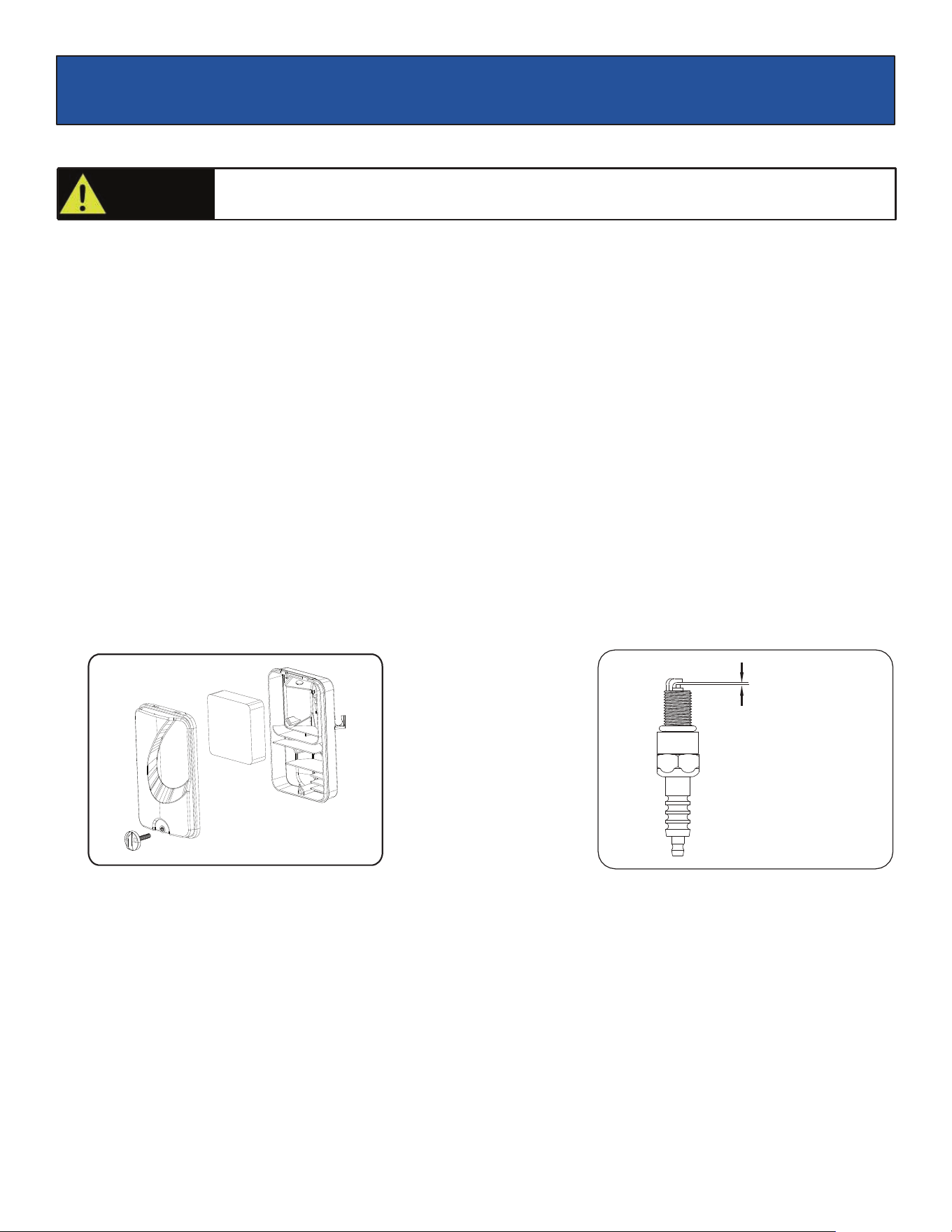
Air Filter (See Fig 20)
A dirty air filter will reduce the lifespan of the engine, make it difficult to start the engine, and reduce the unit’s performance.
•
To clean, remove the air filter cover.
•
Carefully pull the air filter out by lifting along the edges.
•
Remove dirt from filter by tapping on it or having it blown out. Replace with new filter annually.
•
Reinstall air filter so that it seals and replace air filter cover.
Checking Spark Plug (See Fig 21)
•
Disconnect the spark plug wire from the spark plug.
•
Before removing the spark plug, clean the area around its base to prevent debris from entering the engine.
•
Clean carbon deposits off the electrode with a wire brush.
•
Check the electrode gap and gently adjust gap to 0.70mm-0.80mm (.030-.031") if necessary.
•
Reinstall spark plug and tighten to Torque 22–27 Nm (16-20 ft-lb).
•
Reconnect spark plug wire.
•
If spark plug is worn replace only with an equivalent replacement part. Spark plug should be replaced
annually. (BOSCH F7TC, NGK BP6ES, CHAMPION N9YC or equivalent)
Fig 20
Fig 21
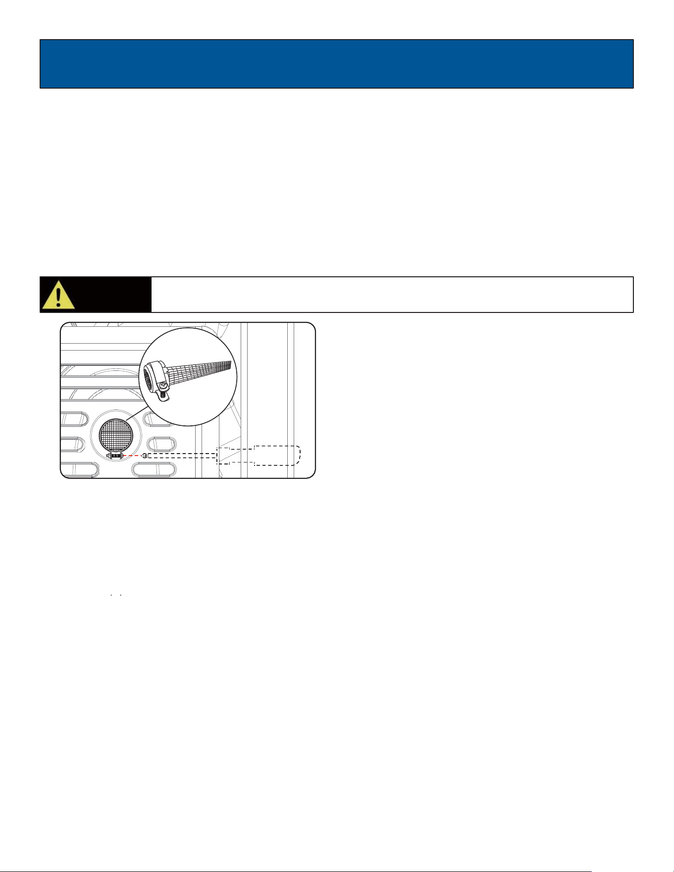
Spark Arrestor (See Fig 22)
•
Inspect the spark arrestor for breaks or holes. replace if necessary. To purchase a replacement spark arrestor contact
PULSAR customer service.
•
Use a brush to remove carbon deposits from the spark arrestor screen as needed.
•
To remove the spark arrestor: While the muffler is cool, loosen the locking clamp and slide the spark arrestor out of the
muffler. Reverse this process to install it.
Cooling System
Cooling system should only be serviced by an authorized dealer.
.760-.800mm
CAUTION!
Used engine oil should be disposed of at an approved disposal site. See your local oil
retailer for more information.
22
MAINTENANCE
High Altitude Operation
At higher altitudes, the standard carburetor air/fuel mixture will be too rich. Performance will decrease, and fuel
consumption will increase. A very rich mixture will also foul the spark plug and cause hard starting. Operation at an
altitude that differs from that at which this engine was certified, for extended periods of time, may increase emissions.
High altitude performance can be improved by specific modifications to the carburetor. If you always operate your
generator at altitudes above 5,000 feet (1,500 meters), have your dealer perform this carburetor modification. This
engine, when operated at high altitude with the carburetor modifications for high altitude use, will meet each emission
standard throughout its useful life. Even with carburetor modification, engine horsepower will decrease about 3.5%
for each 1,000-foot (300-meter) increase in altitude. The effect of altitude on horsepower will be greater than this if no
carburetor modification is made.
Fig 22
Draining Fuel Tank and Carburetor
To help prevent varnish deposits in the fuel system, drain the fuel from the tank and carburetor before storing the unit
for long periods of time. This will help prevent starting problems in the future. If the unit is stored with fuel and the fuel
becomes stale or turns gummy or to varnish the warranty does not cover the resulting repair or service.
Draining the fuel tank
•
Turn the fuel valve to the OFF position.
•
Turn the engine OFF
•
Remove the fuel line that leads from the carburetor to the petcock by squeezing the ends of the hose clamps and sliding
the fuel line off.
CAUTION!
Fuel tank must be empty before replacing fuel filter. Run unit until tank is empty, if needed,
or inspect filter prior to fill-up.
MAINTENANCE
23
•
If needed, install a fuel hose that will extend to a suitable fuel container large enough to catch the fuel being drained
from the tank.
•
Turn the fuel valve to the ON position and open the fuel tank cap slightly to equalize pressure.
•
When the fuel has drained from the tank, close the fuel valve and reinstall fuel line securely on petcock.
Draining the carburetor
•
Turn the fuel valve to the OFF position.
•
Turn the engine OFF.
•
Position a suitable container under the carburetor drain screw to catch fuel; loosen and remove the screw.
•
Allow fuel to drain completely into container, be sure to wipe up any spilled fuel right away.
•
Retighten drain screw, taking care that the gasket seal is in place.
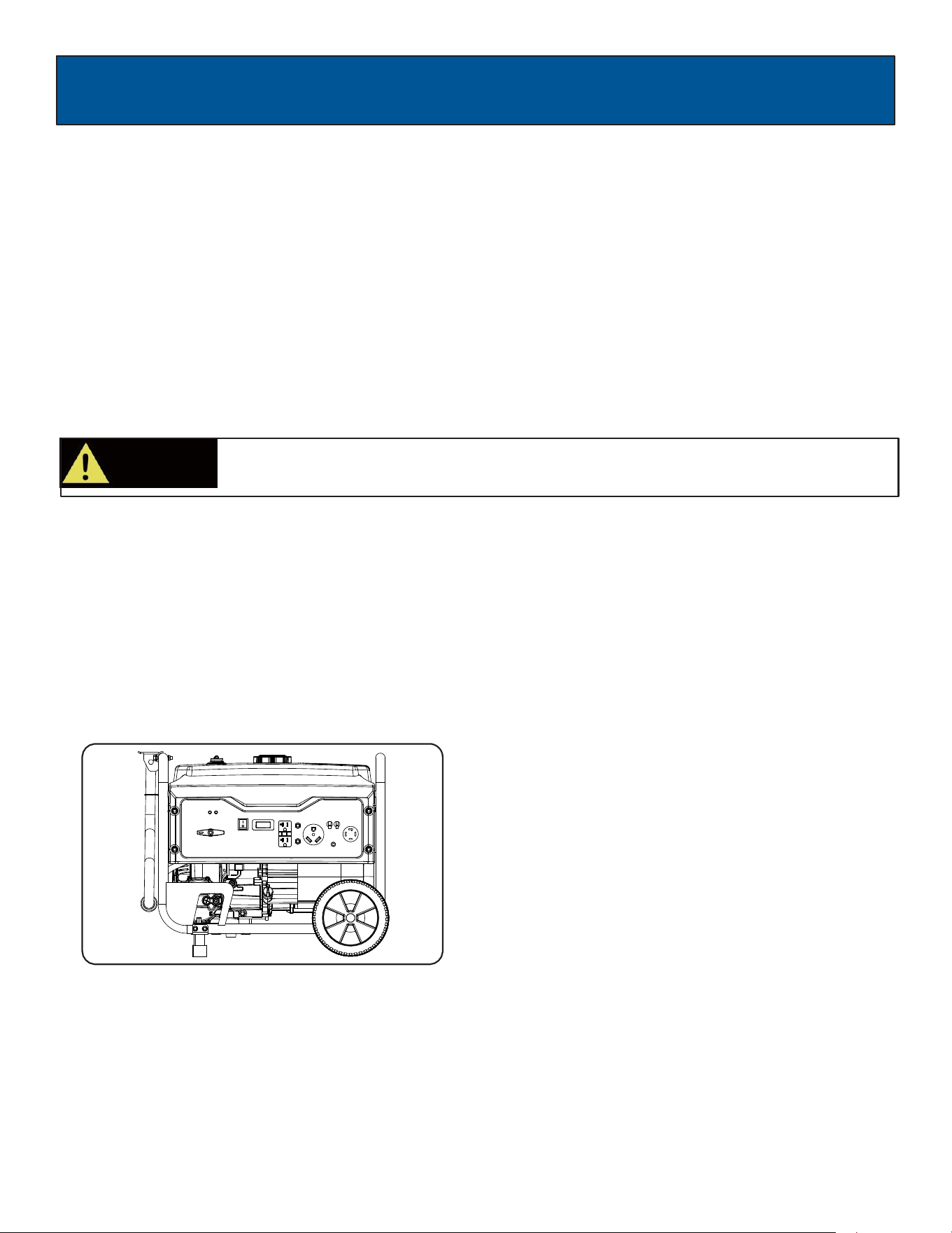
Storage and Transportation of the Generator: (See Fig 23)
•
Remove any debris that has collected on the generator and around the muffler and controls. Use a vacuum cleaner to
pick up loose debris. If dirt is caked on, use a soft bristle brush.
•
Inspect air cooling cylinder fins and flywheel fan. Remove any debris if obstructed.
•
For short-term storage, start generator once every 7 days.
•
For long-term storage, add fuel stabilizer to prevent stale fuel from causing acid and gum deposits in the fuel system
and carburetor.
•
Store in a sheltered location and use a suitable cover to protect from dust.
Fig 23
Engine Long Term Storage:
•
Remove the spark plug and pour about 1 teaspoon of 10W30 Engine oil into the spark plug hole. Reinstall the spark plug.
With the ON/OFF switch in the OFF position pull the recoil starter cord several times to coat the cylinder walls with oil.
•
Slowly pull the recoil starter until you feel the engine build compression (When you feel resistance). Leave the Engine in
this state as this will prevent corrosion on the cylinder walls if stored for a long period of time.
CAUTION!
Consult local hazardous waste management in your area for the proper way to dispose of
used fuel.

24
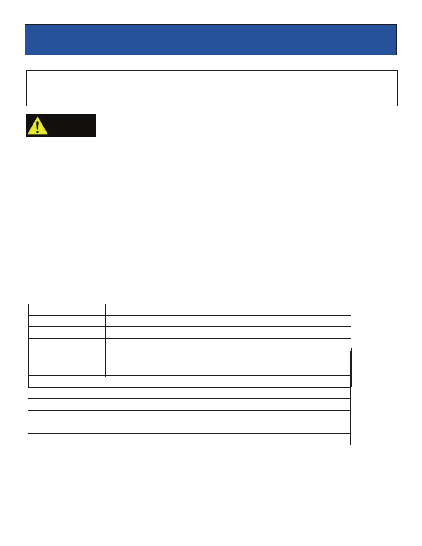
TROUBLESHOOTING
Problem
Cause
Solution
Engine is running, but AC output is not
available
1. Open circuit breaker
2. Poor connection
3. Defective cord set
4. Connected device is faulty
5. Fault in generator
1. Reset circuit breaker
2. Check and repair
3. Check and repair
4. Connect a device that is working
properly
5. Contact service department
Engine runs well without load but bogs
down when loads are connected
1. Short circuit in connected device
2. Generator is overloaded
3. Clogged fuel filter
4. Engine speed is too slow
5. Short circuit in generator
1. Disconnect device
2. See pg 17 “Don’t overload
generator”
3. Clean or replace fuel filter
4. Contact service department
5. Contact service department
Engine will not start, shuts down during
operation, or starts and runs rough.
1.
ON/OFF switch set to “OFF”
2.
Dirty Air filter
3.
Clogged fuel filter
4.
Stale fuel
5.
Spark plug wire disconnected from
spark plug
6.
Bad spark plug
7.
Water in fuel
8.
Fuel valve is in “OFF” position
9.
Over choking
10.
Low oil level
11.
Rich fuel mixture
12.
Intake valve stuck open or
closed
13.
Loss of engine compression
14.
Engine has flooded
1.
Turn switch to “ON”
2.
Replace Air filter
3.
Clean or replace fuel filter
4.
Replace fuel
5.
Reconnect spark plug wire
6.
Replace spark plug
7.
Drain fuel tank and replace fuel
8.
Turn fuel valve to “ON” position
9.
Turn off choke
10.
Fill crankcase to proper oil level &
place generator on a level surface
11.
Contact service department
12.
Contact service department
13.
Contact service department
14.
Wait 5 minutes and crank engine
Engine lacks power
1. Generator is overloaded
2. Clogged fuel filter
3. Dirty Air filter
4. Engine needs servicing
1.
See pg. 17 “Don’t overload
generator”
2.
Clean or replace fuel filter
3.
Replace Air filter
4.
Contact service department
Engine “hunts” or falters
1.
Choke was opened too soon
2.
Clogged fuel filter
3.
Carburetor is running too rich or too
lean
1.
Move choke to middle position until
engine runs smoothly
2.
Clean or replace fuel filter
3.
Contact service department
25
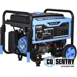
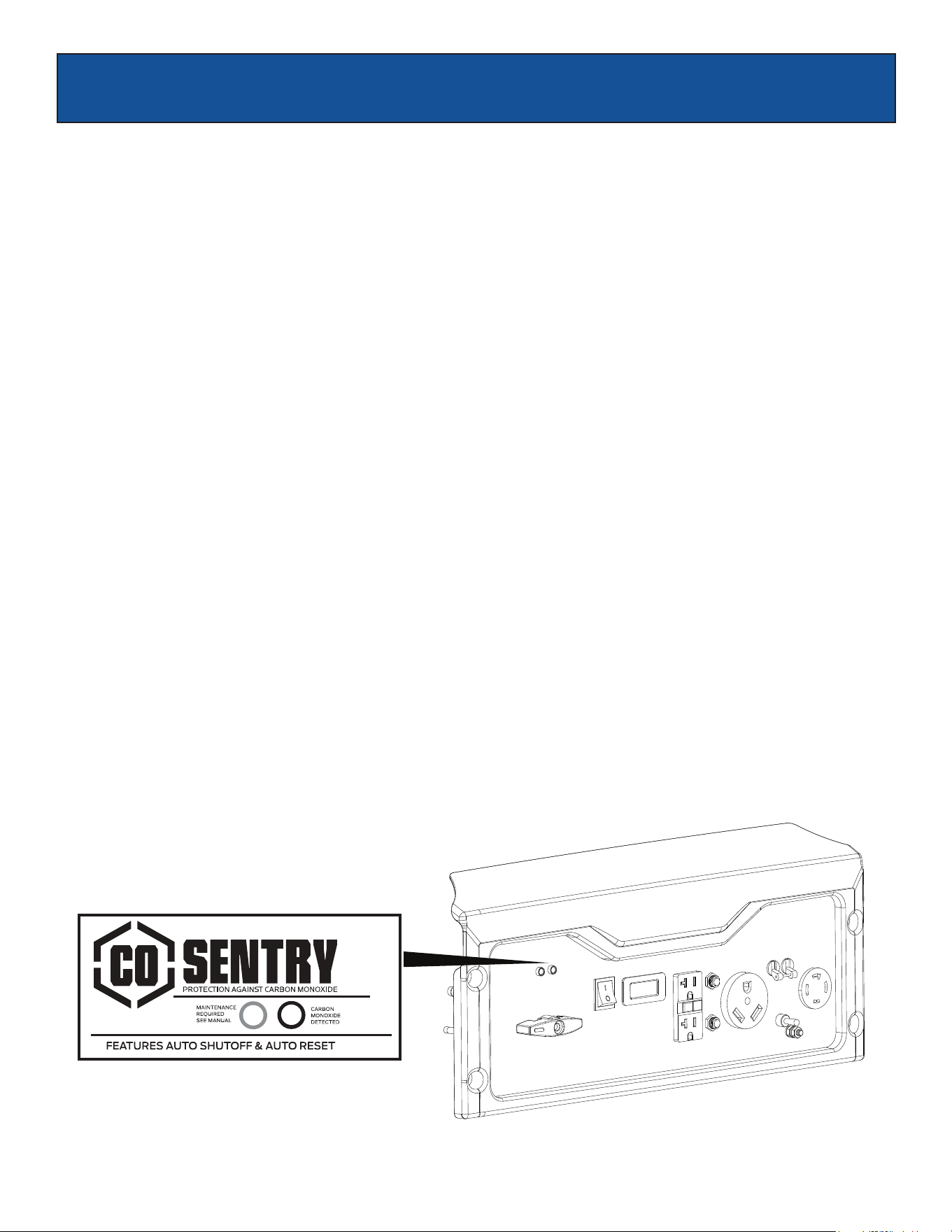
CO SENSOR
CO SENSOR
The CO Sensor monitors for the accumulation of poisonous carbon monoxide gas around the generator when the engine
is running. If increasing levels of CO gas are detected, the CO Sensor automatically shuts down the engine.
The CO Sensor will also detect the accumulation of carbon monoxide from other fuel burning sources used in the area of
operation. For example, if the exhaust of fuel burning tools is pointed at a CO Sensor-equipped generator, a shut-off may
be initiated due to rising CO levels. This is not an error. Hazardous carbon monoxide has been detected. Move and
redirect any additional fuel burning sources to dissipate carbon monoxide away from personnel and occupied buildings.
Note: Remote start-equipped generators must be restarted with the START/STOP button on the control panel after an
automatic shut-down occurs.
Generators are intended to be used outdoors, far from occupied buildings and the exhaust pointed away from personnel
and buildings. If misused and operated in a location that results in the accumulation of CO, like in a partially enclosed area,
the CO Sensor shuts off the engine, notifies the user with a RED indicator light, and directs the user to read the Action
Label for steps to take. The CO Sensor DOES NOT replace carbon monoxide alarms. Install battery-powered carbon
monoxide alarm(s) in your home.
CO SENSOR INDICATOR LIGHTS
RED
Carbon monoxide accumulated around the generator. After shut-off, the RED indicator light in the CO Sensor area of the
control panel will flash to provide notification that the generator was shut-off due to an accumulating CO hazard. The RED
light will flash for at least five minutes after a CO shut-off.
Move the generator to an open, outdoor area far away from occupied spaces with exhaust pointed away. Once relocated to
a safe area, the generator can be restarted. Introduce fresh air and ventilate the area where the generator had shut down.
YELLOW
A CO sensor system fault occurred. When a system fault occurs, the generator is automatically shut down and the
YELLOW indicator light in the CO auto-shutoff area of the control panel will flash to provide notification that a fault has
occurred. The YELLOW light will flash for at least five minutes after a fault. The generator can be re-started, but may
continue to shutoff. A CO sensor fault can only be diagnosed and repaired by an authorized Pulsar service center.
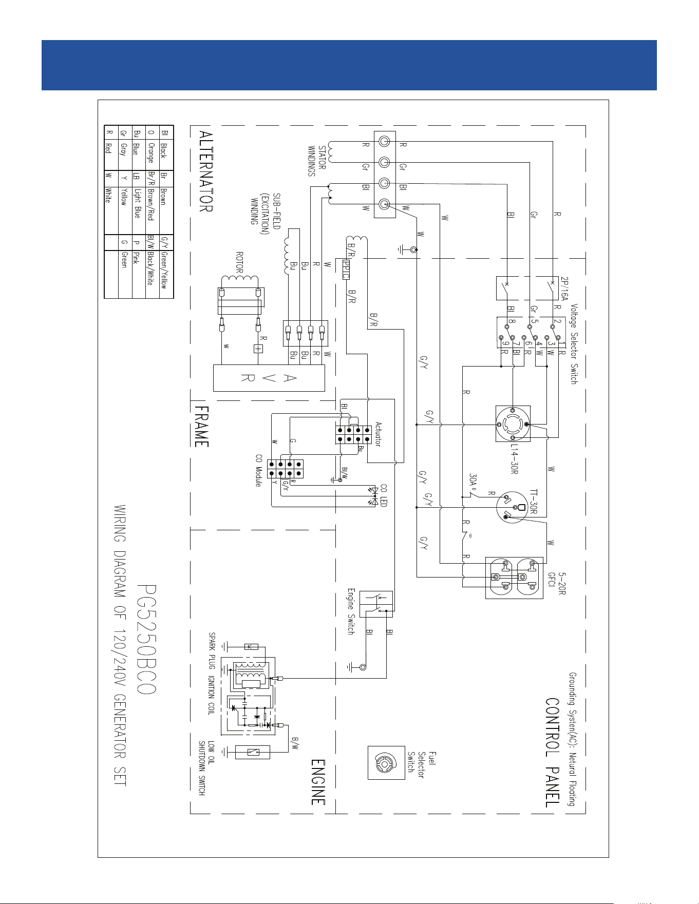
26
DIAGRAMS