Second Setpoint Activation
SHP-O Plus SG-ready
alternate setpoints activation

The following provides information on the heat pump feature for maximising PV self-consumption
and energy savings. It shows the wiring connections that will enable either a higher set point
temperature for the SHP hot water heat pump, or a higher temperature set point plus the electric
heating element running in parallel for maximum solar utility. The settings are enabled from
an external signal transmitter, available from some PV inverters and smart control systems.
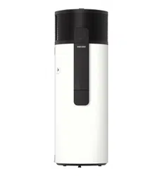
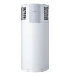
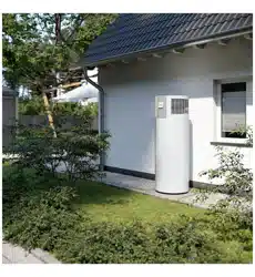
The eco temperature setpoint of the STIEBEL ELTRON SHP heat pumps is 61°C, yet they have the option of heating up
to 65°C when there is ample PV power production, able to provide all the power needed by the units (between 400
W - 700 W compressor, 1500W element). Depending on the wiring of the external switching mechanism, the heat
pump can achieve this by compressor only operation (SG3 mode) or compressor and element operation (SG4 mode).
These temperature points can be adjusted on the MyStiebel App for iOS and Android.
Some solar PV inverter models are equipped with relays/switches intended for load control. These can be programmed
to operate under different scenarios and situations, such as when:
a Solar power generation surpasses and remains above a certain value, or if
b There is export to the electricity grid
These switches can therefore be used for signal control based on a and b conditions.
The 2nd operating mode forcing 65°C tank temperature is enabled when a VAC signal is provided to the heat pump
using this type of controlled switching. This will occur when:
› PV power available is (mostly) enough to operate compressor & fan for several hours
› The electrical energy used is (mostly) self-generated and 'free'.
During this time, heating will store as much energy in the tank as possible.
This turns the unit into a "thermal battery" and since it is storing additional energy it prevents operation at other
hours, particularly when there is no solar radiation and when the electrical supply would come solely from the grid.
All that is required is for the heat pump to detect a 230-240 VAC signal at the designated terminals.
This is how it works
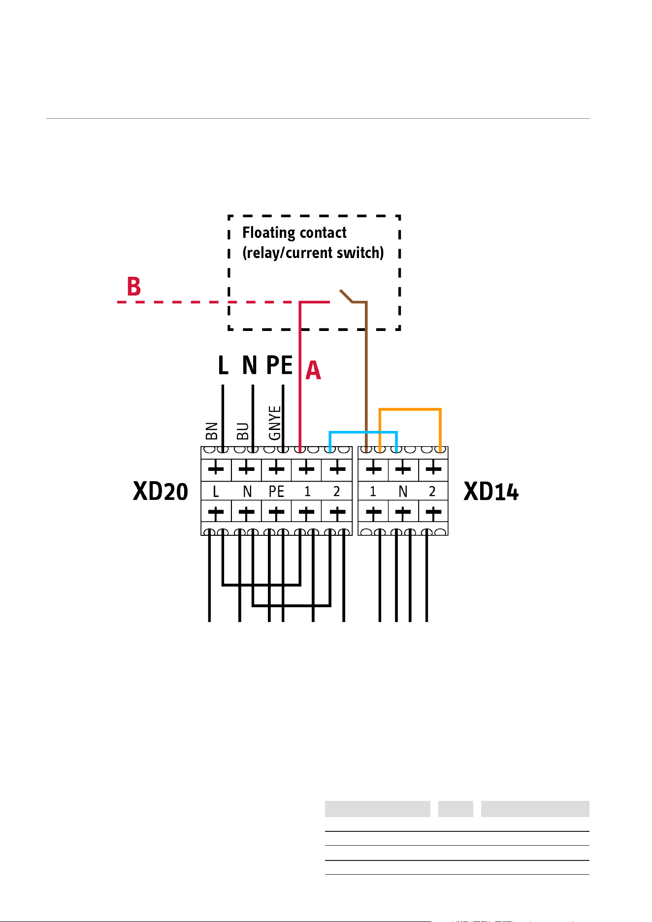
A 230-240 VAC switched signal is required from either the heat pump supply (option A) or an external supply (option B).
A bridged connection is required between terminals XD20.2 and XD14N and from the switched signal to XD14.1 for
SG 3 mode only (compressor to 65°C) or adding another bridged connection between XD14.1 and XD14.2 if SG4 mode
is desired instead (compressor + element to 65°C).
Activation signal
Option A: heat pump supply
Option B: external supply
SG Mode
SG3: brown wire + blue wire
SG4: SG3 + orange wire
Figure 1. Heat pump to external switch
How to wire it
Terminal assignment [XD14]
2 + N
1 + N
no connection
1 + N + 2
SG1 Standby temperatures
SG3
Compressor to 65
°
C
SG2 Program operation mode
SG4 Compressor + element to 65
°
C
Status Modes
For inverters that do not offer load-control relays, an external current
switch can be used.
The current switch takes the place of the inverter relay, providing
also a floating contact, also to be wired to the heat pump terminals
mentioned above. The contact will open or close depending on the
amount of current flow detected from the PV inverter. This current is
used as a proxy for PV power production, ultimately achieving the
same outcome as above.
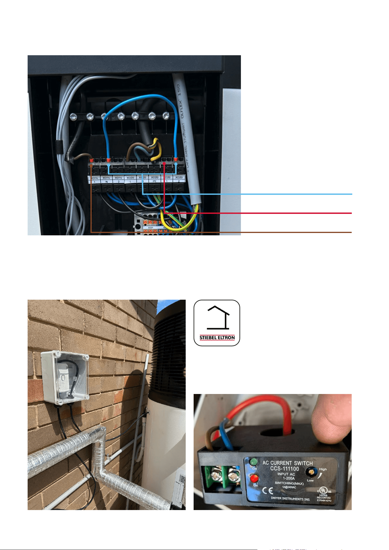
Figure 2. Example SG3 activation wiring – XD 14.1 & XD 20.1 are connected to switched
contacts of an external mechanism
MyStiebel App
Use the MyStiebel App to adjust various
settings for SG3 and SG4 modes. The app
lets you select the temperature and assign
the heating cycle modality (Fast, Balanced,
Efficient) when the signal is present.
from the other contact
of external switch
To be joined
To one contact of the
external signal switch
Figure 3. Relay switch signal control Figure 4. Current switch signal control
Only three connections have to be made:
XD14.N bridged to XD20.2 (blue cable on top),
XD20.1 to one contact of the switching device
(red cable to the right), and XD14.1 to the
other contact of the switching device (brown
cable top left).
What to do when inverters and PV systems do not offer load-control switching
1
Activation must consider expected on-site baseline consumption and 700 W (max) heat pump consumption, plus min. 10% extra
2
This information is for guidance only. It must be vetted by a licensed electrical contractor for accuracy, compliance and suitability of installation under
all applicable rules and regulations, as the case may be. Only licensed individuals can perform electrical work.
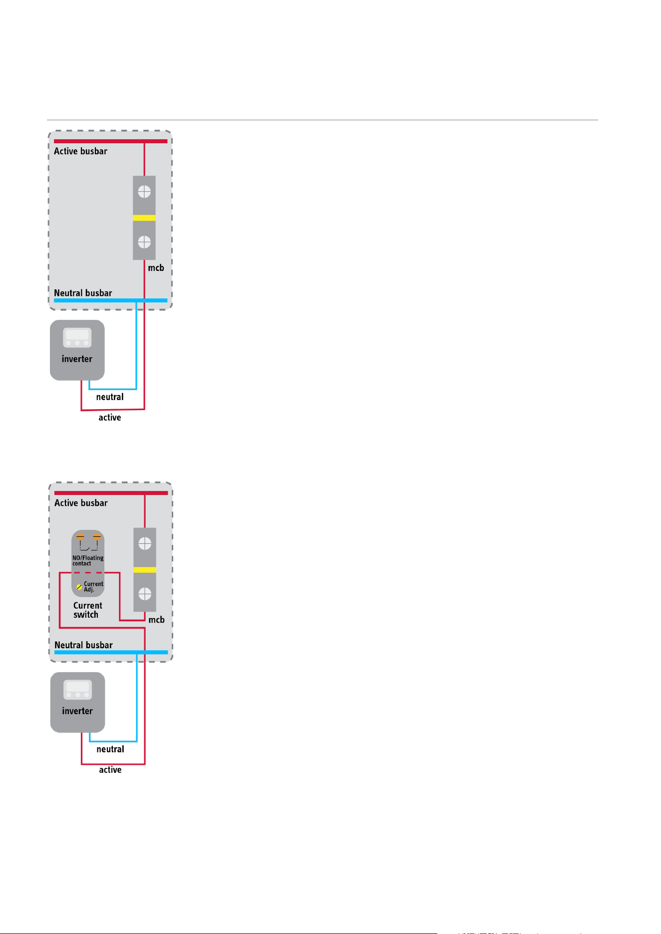
Figure 5. Inverter AC isolation - standard
Figure 6. Inverter AC isolation & current switch
In this case, the switching mechanism (Figure 1) can be provided by an
externally located current switch with adjustable current threshold. This
switch also actuates a normally open/floating contact and does so by
sensing a current flow. In this case, the current flow to be detected is
that of the PV system, usually the PV inverter(s).
Since power = current × voltage, it is easy to calculate the current value
equating to a given power production and a matter of adjusting the
switch to activate when that value is exceeded.
Example
› A PV power production of no less than 1000 W
3
is desired to
enable the second setpoint.
› For voltages between 230-240 VAC, this means a current value in
the range 4.1-4.3 amps.
› The current switch contact is wired to the heat pump.
› The switch is adjusted to operate when the current flow from the
inverter is at the higher end of the range above, so 4.3 A (or even
higher for a more conservative outcome
1
).
This achieves the same result as an in-built inverter relay operating
under condition a).
Since the switch needs to monitor AC current production, it should
be located close to the PV system AC output, typically the inverter AC
isolator (or multiple inverters, if that is the case). The main switch
board will always have such isolators.
The images to the left show the wiring concept
2
, with current switch
& inverter isolator side by side.

More information & selection of a
suitable current switch
Using other control systems
Legal notice | Although we have tried to make this brochure as accurate as possible,
we are not liable for any inaccuracies in its content. Information concerning equipment
levels and specifications are subject to modification. The equipment characteristics
described in this brochure are non-binding regarding the specification of the final prod-
uct. Due to our policy of ongoing improvement, some features may have subsequently
been changed or even removed. Please consult your local trade partner for information
about the very latest equipment features. The images in this brochure are for reference
only. The illustrations also contain installation components, accessories and special
equipment, which do not form part of the standard delivery. Reprinting of all or part of
this brochure only with the publisher’s express permission.
STIEBEL ELTRON (Aust) Pty Ltd
1800 153 351 | info@stiebel-eltron.com.au | www.stiebel-eltron.com.au.
3
Current switching load as low as 0.1 amps is also acceptable, depending on the switching mechanism.
4
Check with your local electrician, electrical supplier or contact Stiebel Eltron for more information.
Most of these switches have some type of induction core through which
the current carrying cable is routed. They usually have a toroidal or
rectangular shape with a “hole” in the middle where the cable goes
through.
Cores can be solid or split, where the latter allow for non-invasive
monitoring and current sensing of electrical equipment already installed
(such as multi-meter current measuring “clamps”).
The simplest units are of the solid core type where the only requisite
for activation is that a current be detected. When the switching needs
to happen at specific current values, means for adjusting the switching
value are necessary (usually by a knob or screw, as illustrated in previous
image).
Some devices are quite sophisticated, able to provide many features,
hysteresis control, large current ranges, high-power contact switching,
digital control & data connectivity options, etc. Unsurprisingly, with
higher complexity and functionality comes an inevitably higher cost.
For the purpose of this document, there are only two basic features
required for a current switch to successfully provide the second setpoint
control signal:
› Adjustable current, able to select values from a minimum of 3
amps and higher.
› The power production threshold desired (eg. 1000 W
3
) will
determine the current selection required, which will determine
what adjustment range is necessary
› Normally open (NO)/floating contact, able to switch a 240 VAC,
1 A, load
5
.
Some switches are quite affordable, priced similarly to regular
electrical components
6
(eg. RCBO).
As indicated in the document, the second setpoint functionality is
originally intended for use with PV systems, but it can be used with
other smart switching mechanisms as well.
As long as a 230-240 VAC signal is present at the terminals
indicated, the unit will heat to the higher setpoint temperature. In
principle, any energy management system that follows a properly
designed control logic protocol aimed at optimising PV power self-
consumption will be able to produce the same (or even better) result
as intended via PV system switching control.
Please contact our Technical Department for additional information
or clarification.