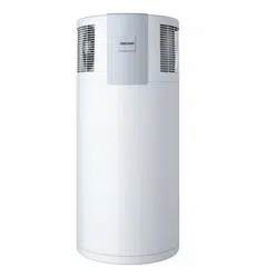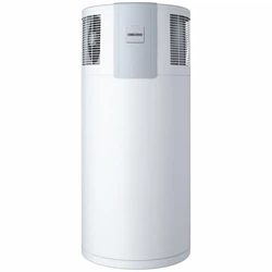
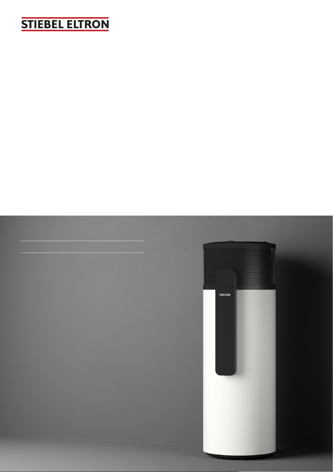
Domestic hot water heat pump
2
SHP-O 200 Plus
SHP-O 300 Plus
Dieses Produkt ist nur für gut isolierte Räume oder
für den gelegentlichen Gebrauch geeignet.
This product is only suitable for well insulated
spaces or occasional use.
Ce produit convient uniquement aux locaux bien
isolés ou à un usage occasionnel.
Dit product is alleen geschikt voor goed geïsoleer-
de ruimtes of voor occasioneel gebruik.
Tento výrobek je vhodný pouze pro dobře izolo-
vané prostory nebo příležitostné použití.
Tento produkt je určený len do dobre izolovaných
priestorov alebo len na príležitostné použitie.
Produkt nadaje się wyłącznie do dobrze zaizolo-
wanych pomieszczeń lub do okazjonalnego kor-
zystania.
A termék kizárólag megfelelően szigetelt helyisé-
gekben vagy alkalomszerűen használható.
Operation and installation

Table of contents
2 | SHP-O Plus www.stiebel-eltron.com
1 Special information................................................... 3
2 General information.................................................. 3
2.1 Units of measurement ...................................... 3
2.2 Symbols in this document ................................ 3
2.3 Target groups................................................... 3
3 Safety........................................................................ 4
3.1 Structure of the warning notices....................... 4
3.2 Intended use .................................................... 4
3.3 Foreseeable misuse.......................................... 4
3.4 Safety instructions............................................ 4
4 Appliance description................................................ 5
4.1 Standard delivery ............................................. 5
4.2 Accessories ...................................................... 5
4.3 Function description......................................... 5
5 Transportation (qualified contractors) ....................... 8
6 Storage ..................................................................... 8
7 Installation (qualified contractors)............................. 9
7.1 Installation site................................................. 9
7.2 Siting the appliance ......................................... 10
7.3 Water connection ............................................. 10
7.4 Condensate drain ............................................. 11
8 Commissioning (qualified contractors) ...................... 11
8.1 Filling the DHW cylinder................................... 11
8.2 Electrical connection ........................................ 11
8.3 Initial start-up.................................................. 14
8.4 Recommissioning............................................. 14
9 Operation.................................................................. 15
9.1 Display and controls......................................... 15
9.2 Pairing the heat pump with the app ................. 15
9.3 Activating/deactivating rapid heat-up............... 16
10 Settings..................................................................... 16
11 Cleaning ................................................................... 16
11.1 Cleaning the casing top .................................... 16
11.2 Cleaning the condensate drain ......................... 16
11.3 Dissolving scale build-up ................................. 16
12 Cleaning (qualified contractors) ................................ 16
12.1 Cleaning the evaporator ................................... 16
13 Troubleshooting........................................................ 17
13.1 Activating/deactivating emergency heating
mode ............................................................... 18
14 Troubleshooting (qualified contractors)..................... 19
14.1 Resetting the high limit safety cut-out .............. 19
14.2 Safety pressure limiter ..................................... 19
15 Maintenance (qualified contractors) .......................... 20
15.1 Descaling the electric emergency/auxiliary
heater.............................................................. 20
15.2 Checking valves ............................................... 21
15.3 Checking consumption indicator on signal an-
ode.................................................................. 21
15.4 Replacing the power cable............................... 21
16 Shutdown (qualified contractors).............................. 22
16.1 Draining the DHW cylinder............................... 22
17 Maintenance and inspection (qualified contractors) .. 22
18 Specification............................................................. 25
18.1 Dimensions and connections............................ 25
18.2 Wiring diagram ............................................... 27
18.3 Data table........................................................ 29
19 Warranty .................................................................. 31
20 Guarantee ................................................................ 32
21 Environment and recycling ....................................... 32
Special information
www.stiebel-eltron.com SHP-O Plus | 3
1 Special information
– The appliance may be used by children over
8 years of age and persons with reduced
physical, sensory or mental capabilities or a
lack of experience and expertise, provided
that they are supervised or they have been
instructed on how to use the appliance
safely and have understood the potential
risks. Children must never play with the ap-
pliance. Cleaning and user maintenance
must not be carried out by children without
supervision.
– Observe all applicable national and regional
regulations and instructions during installa-
tion.
– To prevent injury and damage, only con-
tractors authorised by the manufacturer
may replace the power cable. Use an ori-
ginal spare part.
– Connection to the power supply is only per-
mitted with a suitable mains plug (not in-
cluded in the standard delivery) or only as a
permanent connection. Install safety equip-
ment that allows the appliance to be separ-
ated from the power supply over an isolat-
ing distance of 3mm. Safety equipment in-
cludes contactors, circuit breakers and
fuses.
– The refrigerant used in the appliance is
highly flammable (R290, propane). Only
qualified refrigeration contractors holding
an appropriate Australian or New Zealand
license relevant to the local jurisdiction for
the handling of flammable refrigerants may
perform refrigeration work on the appli-
ance.
– WARNING — FOR CONTINUED SAFETY OF
THIS APPLIANCE IT MUST BE INSTALLED, OP-
ERATED AND MAINTAINED IN ACCORDANCE
WITH THE MANUFACTURER’S INSTRUC-
TIONS.
– WARNING — THIS APPLIANCE MAY DELIVER
WATER AT HIGH TEMPERATURE. REFER TO
THE PLUMBING CODE OF AUSTRALIA (PCA),
LOCAL REQUIREMENTS AND INSTALLATION
INSTRUCTIONS TO DETERMINE IF ADDI-
TIONAL DELIVERY TEMPERATURE CONTROL
IS REQUIRED.
2 General information
u Read these instructions carefully before using the
appliance and retain them for future reference.
Information for Australia and New Zealand
This appliance must be installed in accordance with
the Plumbing Code of Australia (PCA) and the New
Zealand Building Code.
2.1 Units of measurement
All measurements are given in mm unless stated otherwise.
2.2 Symbols in this document
Symbol Meaning
This symbol indicates possible property damage,
equipment damage, consequential damage or envir-
onmental damage.
General information is indicated by the adjacent
symbol.
This symbol indicates that you have to do something.
This symbol indicates that you must fulfil certain
prerequisites before you perform the following
steps.
This symbol indicates a result or intermediate result.
These symbols show you the software menu level (in
this example level3).
This symbol indicates a reference to the correspond-
ing page number (page11 in this example).
2.3 Target groups
Operator
Person without specialist expert knowledge
Qualified heating contractor
Person with specialist expert knowledge in the following areas:
heating technology, heating media, building services and engin-
eering, ventilation and air conditioning technology, measuring
technology, heat pump technology, environmental technology,
occupational safety and fire safety
Qualified electrical contractor
Person with specialist expert knowledge in the following areas:
electrical engineering, measuring technology, occupational
safety and fire safety
Qualified refrigeration technology contractor
Person with specialised knowledge in the following areas: elec-
trical, plumbing and refrigeration work, electrical engineering,
measurement technology, occupational safety and fire protec-
tion
Apprentice
Apprentices may only carry out the assigned tasks under profes-
sional supervision and instruction.
Professional qualification
Subject to local regulations, a training course, a higher educa-
tion qualification or further development training will be re-
quired.
en
Safety
4 | SHP-O Plus www.stiebel-eltron.com
3 Safety
3.1 Structure of the warning notices
3.1.1 Section-specific warning notices
Section-specific warning notices apply to all steps in the section.
Injury
CAUTION
Type and source of risk
Consequence(s) of failure to observe the warning no-
tice
u Hazard prevention measure(s)
Property damage, consequential losses, environmental
pollution
NOTICE
Type and source of risk
Consequence(s) of failure to observe the warning no-
tice
u Hazard prevention measure(s)
3.1.2 Embedded warning notices
Embedded warning notices apply only to the step immediately
following the notice.
u
SIGNAL WORD: Consequence(s) of failure to observe the
warning notice. Hazard prevention measure(s).
Step to
which the warning notice refers
3.1.3 Key to symbols
Symbol Type of risk
Injury
Electrocution
Burns, scalding
3.1.4 Signal words
Signal
word
Meaning
DANGER Failure to observe this information will result in
death or serious injury.
WARNING Failure to observe this information may result in
death or serious injury.
CAUTION Failure to observe this information may result in
moderate or minor injury.
NOTICE Failure to observe this information may result in
property damage, consequential losses or environ-
mental damage.
3.2 Intended use
The appliance is designed to heat drinking water.
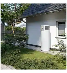
The appliance is designed for indoor and outdoor installation.
The appliance is intended for domestic use. The appliance can
also be used in non-domestic environments, e.g.in small busi-
nesses, as long as it is used in the same way.
Observation of these instructions, the instructions for any ac-
cessories used as well as the specifications also forms part of
the correct use of this appliance.
3.3 Foreseeable misuse
Any other use beyond that described shall be deemed to be out-
side the intended use.
Heating liquids other than potable water is not permitted.
Ambient temperatures below the application limit
If the lower application limit is undershot, the safety equipment
switches the compressor off. The electric emergency/auxiliary
heater takes over the DHW heating for a period of 60minutes.
After this period, the application limit is checked again. If the
ambient temperature is again below the permissible temperat-
ure value, the electric emergency/auxiliary heater continues
DHW heating.
Ambient temperatures above the application limit
If the upper application limit is exceeded, the safety equipment
switches the compressor off. The electric emergency/auxiliary
heater takes over the DHW heating for a period of 60minutes.
After this period, the application limit is checked again. If the
ambient temperature is again above the permissible temperat-
ure value, the electric emergency/auxiliary heater continues
DHW heating.
3.4 Safety instructions
Injury
– If the insulation or individual components are damaged,
there is a risk of fatal electrocution. If such damage has oc-
curred, switch off the power supply and arrange a repair.
– The work described in this manual requires specialised
knowledge of electrical engineering and heating techno-
logy. If the work described is carried out without the appro-
priate expertise, this may result in injury. Only qualified
contractors are permitted to work on the appliance.
– The water in the DHW cylinder can be heated to temperat-
ures in excess of 60°C. There is a risk of scalding at outlet
temperatures in excess of 43°C. Ensure you do not come
into direct contact with the outflowing water or components
that have heated up.
– If refrigerant escapes in high concentrations, it can cause
symptoms such as headaches, loss of consciousness or ir-
regular heartbeat. Avoid direct skin contact and do not in-
hale the vapours. Ventilate the rooms affected. Please note
that refrigerants are odourless.
– The refrigerant is highly flammable. Keep the installation
site clear of heat, sparks and other ignition sources, in par-
ticular in the event of a leak. The appliance may only be
stored in rooms without a permanent source of ignition
(e.g. naked flame, switched-on gas appliance, electric
heater).
– In their original condition, electrical components are not
sources of ignition (e.g. hot surface, sparking or arcing) and
cannot ignite the refrigerant in the event of a leak. Only use
the recommended original spare parts.
– Unsuitable spare parts and accessories may jeopardise user
and product safety. Only use original spare parts and ori-
ginal accessories.
– Safe use is not guaranteed if installation of the appliance is
incomplete. Only operate the appliance once installation is
complete. Only operate the appliance with the casing and
cover closed.
Appliance description
www.stiebel-eltron.com SHP-O Plus | 5
– WARNING: If the hot water unit is not used for two or more
weeks, an amount of highly flammable hydrogen gas may
accumulate in the water tank. To dissipate this gas safely, it
is recommended that a hot tap be turned on for several
minutes or until discharge of gas ceases. Use a sink, basin
or bath outlet, but not a dishwasher, clothes washer or
other appliance. During this procedure, there must be no
smoking, open flame or any electrical appliance operating
nearby. If hydrogen is discharged through the tap, it will
probably make an unusual sound as with air escaping.
Property damage, consequential losses, environmental
pollution
– Poor air quality can damage the appliance. Keep the appli-
ance installation site free from air contaminated with oil or
salt (chloride). Keep the installation site free from corrosive
and explosive substances. Avoid contaminating the installa-
tion site with dust, hairspray or substances containing
chlorine or ammonia.
– If the air supply is restricted, the operational reliability of
the appliance cannot be guaranteed. Never cover the appli-
ance.
– The appliance may be damaged if the DHW cylinder is
empty and the appliance is switched on. Only operate the
appliance when the DHW cylinder has been filled.
– Hoses and insulation may be damaged if laid incorrectly.
Avoid kinking or excessively compressing hoses and insula-
tion.
Emergency shutdown
u Interrupt the power supply by removing the fuse/switching
off the miniature circuit breaker (MCB).
u Close the cold water inlet.
4 Appliance description
4.1 Standard delivery
– 1×condensate drain bend
– 1× T&P relief valve Rp½
– 2× straight pipe adaptors from G1 to Rp¾
– 2× insulation sleeve
– 2× pipe insulating bushes, preinstalled
4.2 Accessories
4.2.1 Required accessories
Various safety valves are available depending on the water sup-
ply pressure. These safety valves protect the appliance against
unacceptable excess pressure.
4.3 Function description
SHP-O 200 Plus SHP-O 300 Plus
Air source heat
pump
x x
Water source heat
pump
- -
Ground source heat
pump
- -
Low temperature
heat pump
- -
Auxiliary heater x x
The appliance is designed to supply DHW to multiple draw-off
points.
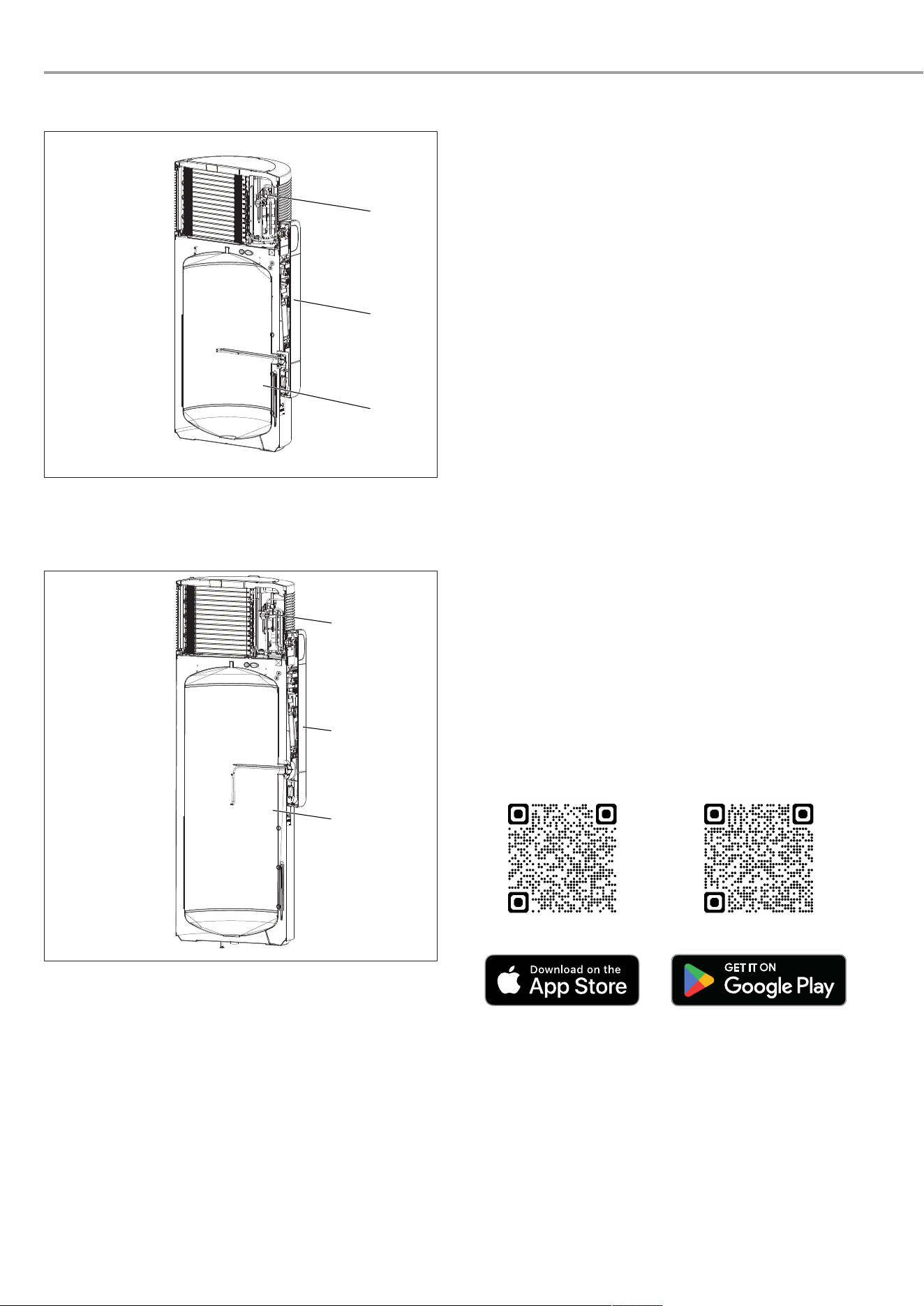
Function
There is a closed circuit within the heat pump which contains
refrigerant.
– The heat pump extracts heat from the ambient air, which is
transferred to the refrigerant in the refrigerant circuit inside
the evaporator.
– The evaporator heats the refrigerant further so that it
changes from a liquid to a gaseous state.
– The compressor draws in the gaseous refrigerant and com-
presses it. This increase in pressure raises the refrigerant
temperature.
– In the downstream condenser, the refrigerant then transfers
heat to the DHW cylinder. The refrigerant changes to a li-
quid state.
– The liquid refrigerant flows through an expansion valve,
which reduces the pressure and temperature of the refri-
gerant.
– The cycle begins again.
– When a DHW draw-off point is opened, cold incoming water
forces the domestic hot water out of the appliance.
1 2 3
8
9
10
11
7
4
5
6
D0000112018
1 Heat source 2 Heat pump (refrigerant
circuit)
3 Heat distribution system
(heating circuit)
4 Air
5 Ground 6 Water
7 Environmental energy 8 Evaporator
9 Compressor 10 Condenser
11 Expansion valve
The lower the temperature of the intake air and the higher the
selected set temperature, the longer the heat-up time. The heat-
ing output of the heat pump drops and the demand for electrical
energy increases.
Appliance design
The heat pump unit is located in the upper section of the heat
pump.
The heat pump is controlled electronically.
Subject to the power supply and your draw-off patterns, the
heat pump automatically heats water to the selected set temper-
ature.
The DHW cylinder is located in the lower section of the heat
pump. To protect against corrosion, the DHW cylinder is coated
internally with special enamel and equipped with a protective
anode.
en
Appliance description
6 | SHP-O Plus www.stiebel-eltron.com
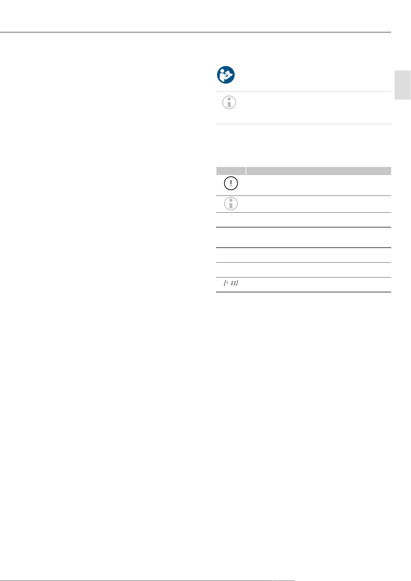
SHP-O 200 Plus:
2
1
3
D0000117567
1 Heat pump unit 2 Control panel with pro-
gramming unit
3 DHW cylinder
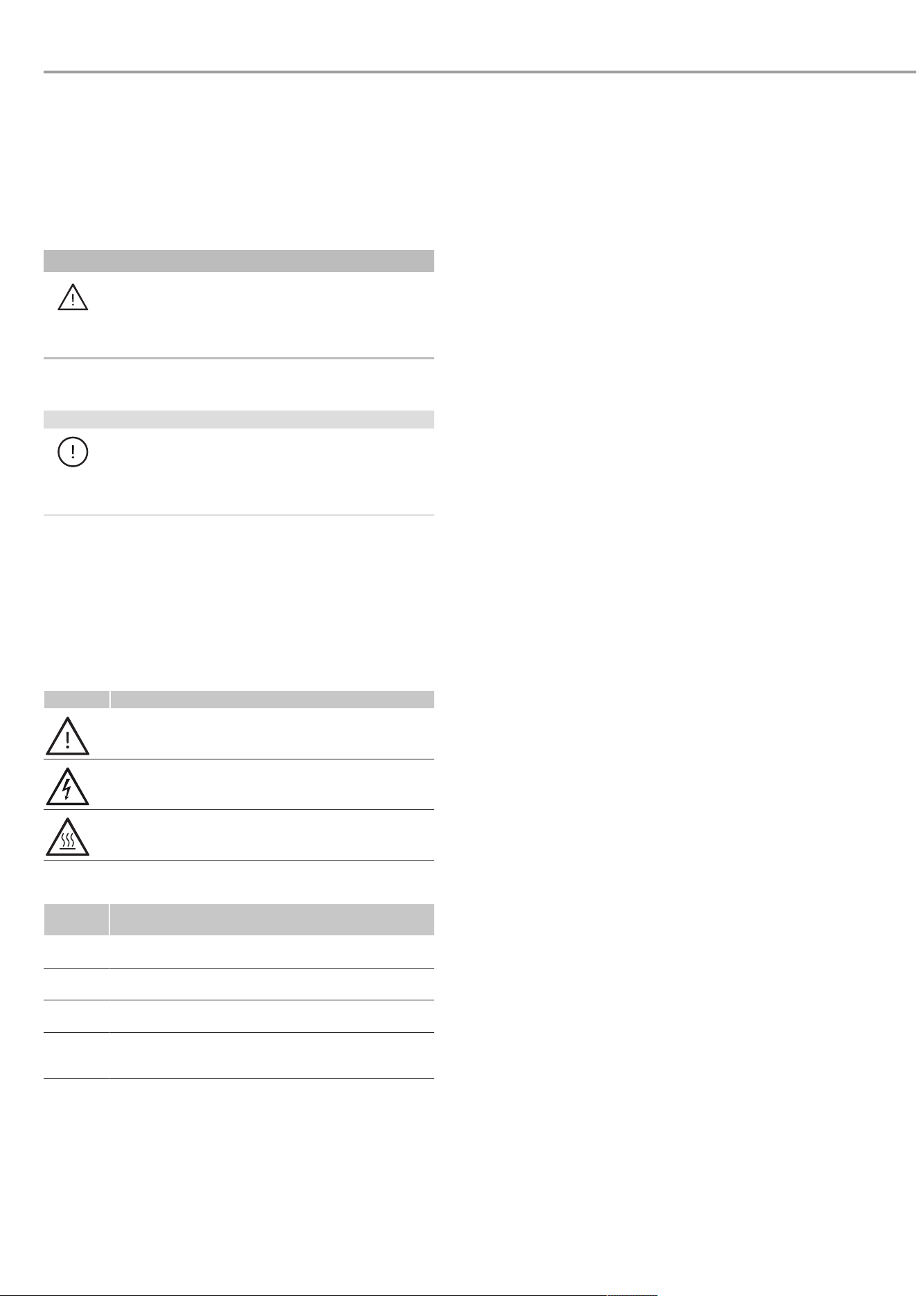
SHP-O 300 Plus:
1
2
3
D0000120790
1 Heat pump unit 2 Control panel with pro-
gramming unit
3 DHW cylinder
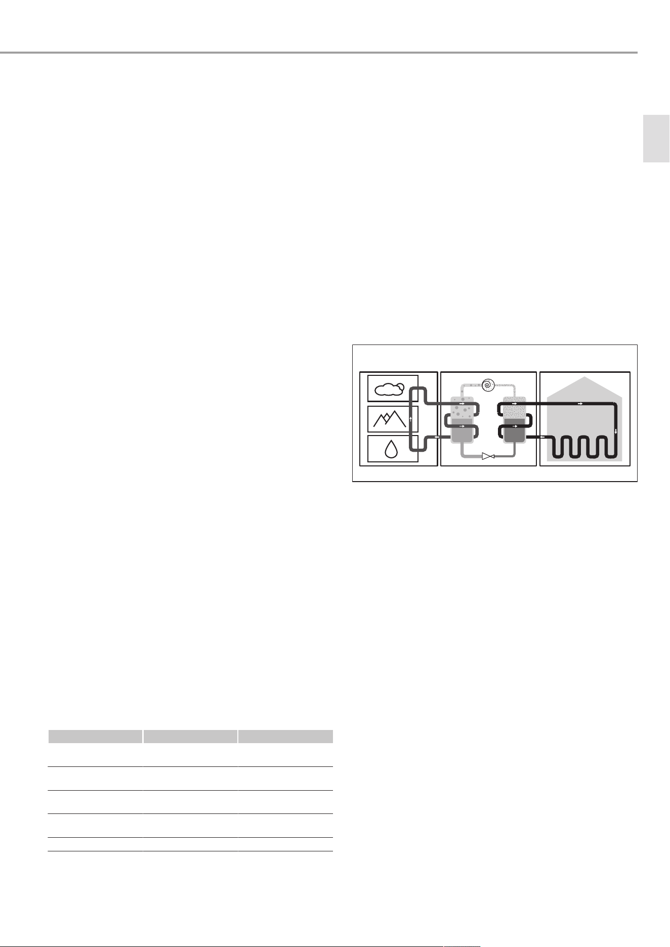
4.3.1 Apps
You can connect the appliance directly and locally to one of our
apps (MyStiebel app for operators and Servicewelt app for qual-
ified contractors) via the integrated WLAN module. You do not
need a separate internet connection for the Servicewelt app.
If the internet connection is selected in the app and permission
is granted under data protection law, both apps can access the
appliance from anywhere. The qualified contractor can then also
access the device via the Servicewelt web portal. The Ser-
vicewelt app is the mobile extension of the Servicewelt as an in-
ternet portal.
You can use the following functions with the MyStiebel app:
– Establish a connection between a smartphone and the ap-
pliance from anywhere in the world (integration in the
cloud)
– Set the temperature
– Set the heating type (efficient, balanced, fast)
– Activate/deactivate time programs
– Activate/deactivate the hygiene program
– Activate/deactivate the holiday program
– Activate/deactivate additional comfort functions (DHW Plus)
– Activate/deactivate DHW boost
– View appliance information
– View appliance errors
– Set the LED light intensity
– Lock/unlock buttons
– Activate/deactivate emergency mode
– Implement settings for use in combination with a photovol-
taic system
You can use the following functions with the Servicewelt app:
– Set different operating modes (time programs, energy man-
agement)
– Set different temperatures for each operating state
– View and set various system parameters
– View current events, such as changes to parameters and
system messages
– Download parameter sets and send them to us for analysis
– Upload previously saved parameter sets (only with con-
firmed customer account)
– Perform relay tests to start up the compressor and fan (only
with a confirmed customer account)
The apps offer additional functionality for operators and for ser-
vice and installation purposes for qualified contractors.
The appliance can be operated via an app and the buttons on
the appliance.
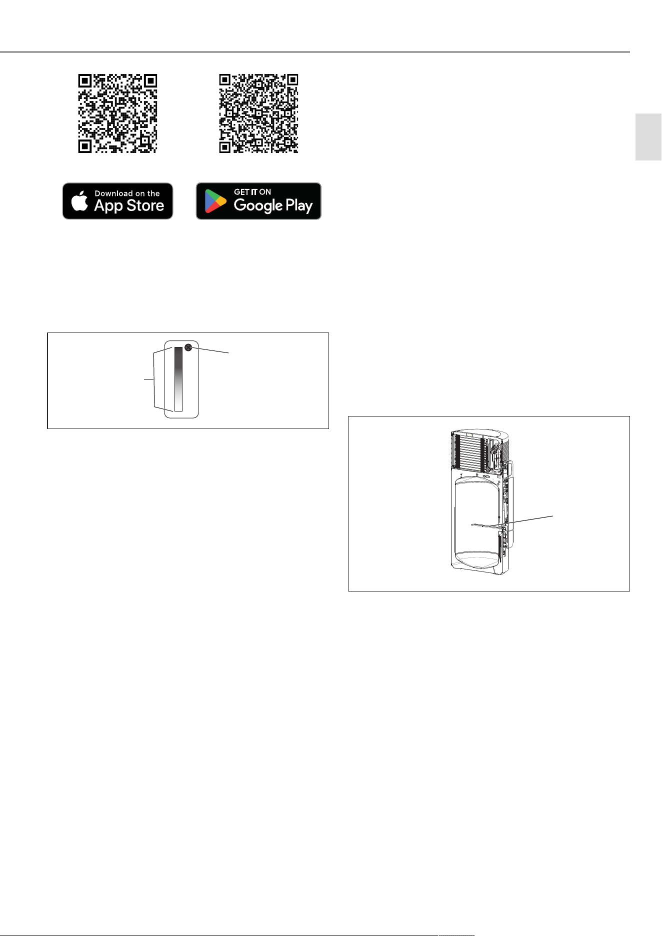
The apps are available in the App Store® and Google Play
Store™.
MyStiebel MyStiebel
Appliance description
www.stiebel-eltron.com SHP-O Plus | 7
Servicewelt Servicewelt
4.3.2 DHW heating
The appliance is equipped with two temperature sensors.
– The cylinder top sensor captures the water temperature in
the upper section of the cylinder.
– The integral sensor determines the average cylinder tem-
perature.
1
2
D0000050335
1 Cylinder top sensor 2 Integral sensor
The MyStiebel app displays the temperature in the upper section
of the cylinder, which is captured by the cylinder top sensor. The
control unit additionally uses the average cylinder temperature
captured by the integral sensor.
DHW heating starts in the following cases:
– The actual temperature determined by the cylinder top
sensor is ≥3K lower than the set temperature.
– The available mixed water amount drops to the percentage
share of the maximum mixed water amount set in the para-
meter "charge level". The available mixed water amount is
calculated on the basis of the average cylinder temperature.
The mixed water amount is only calculated if the water
temperature in the upper and middle section of the cylinder
is higher than 40°C (±0.5K).
4.3.3 Defrost monitoring
The appliance is equipped with an electronic defrost monitor.
Low air intake temperatures may result in the formation of hoar
frost on the evaporator depending on the air humidity and DHW
temperature.
The appliance starts the defrosting process when the air intake
temperature and the evaporator temperature fall below the set
limits.
During the defrosting process, DHW heating with the heat pump
(compressor) is interrupted. If the electric emergency/auxiliary
heater was already activated, it remains active.
In the MyStiebel app, it is possible to activate the electric emer-
gency/auxiliary heater to heat the water.
If it is necessary to defrost the evaporator, the heat-up pro-
cesses will take longer.
The appliance switches off the compressor during the defrosting
process. The fan continues to run.
The defrosting process is shown in the MyStiebel app until it fin-
ishes.
4.3.4 Frost protection/ holiday
The operating modes must be activated in order to use the func-
tions.
The appliance activates a frost protection function if the DHW
temperature is below a limit value (<8°C).
The appliance heats the water with the heat pump. If the tem-
perature falls below the application limit or the temperature in
the DHW cylinder drops, the electric emergency/auxiliary heater
is switched on.
The heat pump and electric emergency/auxiliary heater switch
off once the DHW temperature is above the limit value again.
4.3.5 Electric emergency/auxiliary heater
Water is normally heated by the heat pump of the appliance.
If the temperature falls below or exceeds the application limits,
the electric emergency/auxiliary heater takes over DHW heating
to the set temperature. Heat pump operation is interrupted.
Every hour, the control unit once again checks whether the ap-
plication limits are being adhered to.
Once the appliance is operating within the application limits
again, the electric emergency/auxiliary heater switches off and
DHW heating continues with the heat pump.
1
D0000117567
1 Electric emergency/auxili-
ary heater
Emergency heating mode
Emergency heating mode can be used to start up the electric
emergency/auxiliary heater (see chapter
Activating/deactivating
emergency heating mode [}18]
).
Rapid/comfort heat-up
If a one-off demand for extra hot water arises, you can activate
this function (see chapter
Activating/deactivating rapid heat-up
[}16]
).
4.3.6 External signal transmitter
External signal transmitters can be integrated via the built-in
contact input, e.g. a photovoltaic system to make use of solar
power generated on site.
4.3.7 External switching device
The device can be operated with an external switching device
that interrupts the power supply to the appliance. This can be,
for example:
– External time switch
– Switched socket
en
Transportation (qualified contractors)
8 | SHP-O Plus www.stiebel-eltron.com
– Energy management system
– Signal from the power supply utility (EVU) that interrupts
the power supply
4.3.8 Runtime-dependent rapid heat-up
Only use the runtime-dependent rapid heat-up function if in-
structed to do so by us. Activating this function is likely to affect
the efficiency of the appliance and can lead to unnecessarily
higher energy consumption and higher operating costs.
The appliance offers the option of runtime-dependent rapid
heat-up. If the selected set temperature is not reached by the
heat pump after a user defined period, the appliance switches
on the electric emergency/auxiliary heater in parallel to back up
the heat pump (subject to this function being enabled).
Once the set temperature has been reached, the electric emer-
gency/auxiliary heater is deactivated until the set runtime has
elapsed again following a heat demand. This function is dis-
abled at the factory.
5 Transportation (qualified contract-
ors)
Observe the following information:
– The appliance has a high centre of gravity and low over-
turning moment.
– The appliance casing is not designed to withstand strong
forces.
– The appliance is easier to transport in its packaging than
unpacked.
u Observe the transport information on the back part of the
box.
u Transport the appliance in dry conditions and at temperat-
ures between 0°C and +45°C.
u Transport the appliance vertically. You can transport the ap-
pliance horizontally for a short time (max. 24hours) on flat,
smooth roads. In this case, lie the appliance on its back.
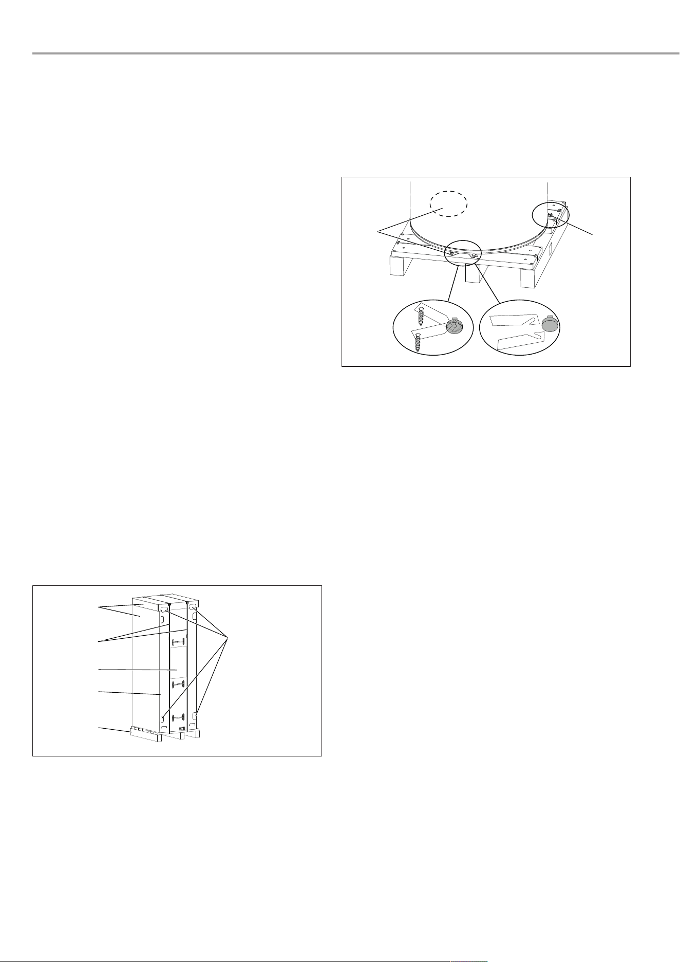
1
3
4
2
6
5
D0000117582
1 Recessed grips 2 Pallet
3 Back part of the box 4 Transport information
5 Vertical straps 6 Cardboard sleeve
Transporting the appliance in its box on a pallet
u Use the recessed grips and the bottom section of the pallet
to carry the appliance.
Only transport appliance with cardboard back panel on a pallet
u Cut the vertical straps.
u Remove the cardboard sleeve from the appliance.
u Carry the appliance to its installation site by the recessed
grips.
Only transport appliance with cardboard back panel without a
pallet
u Cut the vertical straps.
u Remove the cardboard sleeve from the appliance.
2.
1.
1
1
D0000034798
1 Metal bracket with screw
u Remove the screws from all metal brackets on the pallet.
u WARNING:Sharp edges on the metal brackets can cause
cutting injuries. Handle the metal brackets with care.
u Push the metal brackets towards the centre of the appliance
to unhook them from the appliance feet.
u Pull the metal brackets out from underneath the appliance.
u WARNING:If the appliance is tilted too far, it may tip over
and cause injury. Take note of the appliance's weight and
centre of gravity. Slightly tip the appliance and carefully roll
it off the pallet.
u Carry the appliance to its installation site by the recessed
grips.
6 Storage
Store the appliance
– Vertically
– Dry
– Dust-free
– Free from aggressive substances
– Covered (if it has been unpacked)
– at temperatures between 0°C and +45°C
Installation (qualified contractors)
www.stiebel-eltron.com SHP-O Plus | 9
7 Installation (qualified contractors)
7.1 Installation site
Property damage, consequential losses, environmental
pollution
– Observe the need for a properly drained safe-tray under the
appliance where leakage may cause damage.
Appliance damage
– The installation site must be free from direct and severe
weather influences.
– The air intake and air discharge must be unobstructed.
– The installation site must be well ventilated.
– The installation site must be free from flammable, highly
combustible gases and substances, as well as high levels of
dust.
– The substrate of the installation site must be level and have
sufficient load bearing capacity. Take note of the weight of
the appliance with a full DHW cylinder. If the appliance is
not level, there is a risk of appliance damage.
– In the case of indoor installation, the size of the installation
room must correspond to the application limits of the appli-
ance (see chapter
Data table [}29]
).
– The installation site must not be close to outdoor air condi-
tioning units. This can damage the fan, compressor and
evaporator.
– Contaminated air can cause corrosion of copper materials
in the refrigerant circuit. The evaporator may corrode, caus-
ing the appliance to fail. Do not install the appliance in
areas where the following substances are present.
Impermissible substance Example of installation site
with impermissible sub-
stance
Atmospheres containing am-
monia
Sewage works, pigsties
Substances which block the
evaporator
Air containing oil, fat or dust
(cement, flour, etc.). Notice: If
the air contains hairspray (e.g.
in hairdressing salons), the ap-
pliance should be operated
with shorter maintenance in-
tervals.
Saline environments Coastal installations (<200m
from the coast) can reduce
component service life.
Atmospheres containing chlor-
ine or chloride
Swimming pools, salt works
Atmospheres containing
thermal water
Formaldehyde in the atmo-
sphere
Certain wood-based materials
(e.g. OSB boards)
Certain insulating materials
(e.g. foams based on urea-
formaldehyde (UF in-situ
foams))
Carboxylic acid in the atmo-
sphere
Extract air from kitchens
Components of floor cleaners
(e.g. vinegar cleaner)
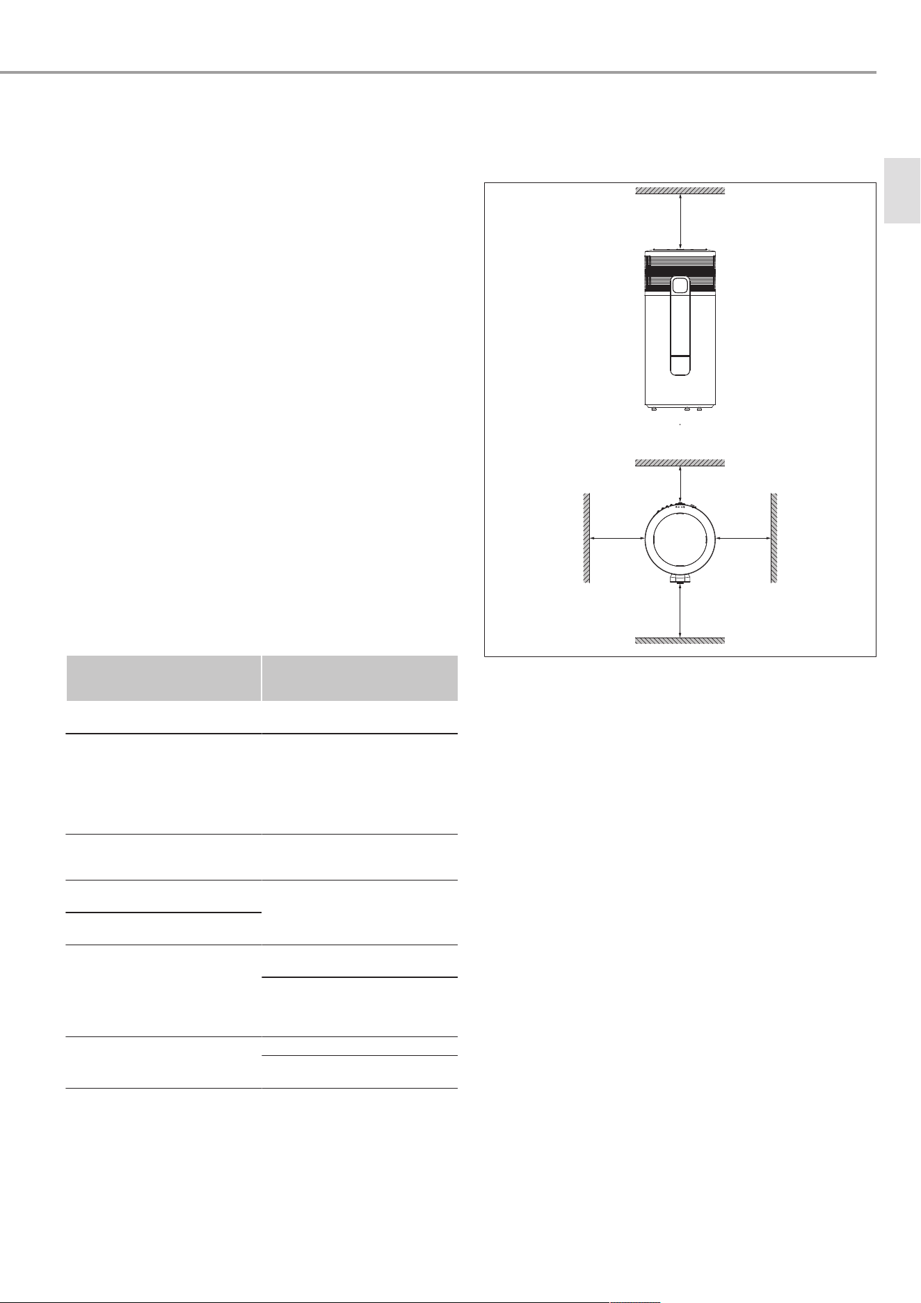
Minimum clearances
– Leave sufficient space to provide access for installation,
maintenance and cleaning. Maintain the required minimum
clearances.
≥150
≥150
≥400
≥400
≥500
1:1
e
2,2
c
1,5
D0000117566
Efficiency
– To keep the pipe runs as short as possible, install the appli-
ance close to kitchens or bathrooms.
– The appliance performance data is calculated according to
the relevant standards, using the intake temperature spe-
cified in the data table. Below this temperature the appli-
ance efficiency and output decrease. The heat-up time is
extended.
Recirculation air mode
– The appliance must not impair the operation of other appli-
ances in the installation room.
– Other appliances in the installation room must not interfere
with operation of the heat pump.
– You can improve the efficiency of the appliance by utilising
the waste heat from other appliances to heat the domestic
hot water, e.g. boilers, tumble dryers or freezers.
Sound emissions
– The sound emissions are louder on the air intake and air
discharge sides of the appliance than on the closed sides.
Do not direct the air intake or air discharge towards noise-
sensitive rooms of the house, e.g. bedrooms.
– To prevent adverse effects from operating noise, avoid in-
stalling the appliance close to bedrooms.
en
Installation (qualified contractors)
10 | SHP-O Plus www.stiebel-eltron.com
7.2 Siting the appliance
u Cut the vertical straps.
u Remove the cardboard sleeve from the appliance.
2.
1.
1
1
D0000034798
1 Metal bracket with screw
u Remove the screws from all metal brackets on the pallet.
u WARNING:Sharp edges on the metal brackets can cause
cutting injuries. Handle the metal brackets with care.
u Push the metal brackets towards the centre of the appliance
to unhook them from the appliance feet.
u Pull the metal brackets out from underneath the appliance.
u WARNING:If the appliance is tilted too far, it may tip over
and cause injury. Take note of the appliance's weight and
centre of gravity. Slightly tip the appliance and carefully roll
it off the pallet.
u Position the appliance at the final installation site.
u Cut the horizontal straps.
u Remove the back part of the box from the appliance.
u Maintain the minimum clearances.
D0000117568
u NOTICE:If the appliance is not positioned vertically, both
the appliance and the installation site may be damaged if
condensate runs out. Level the appliance at the height-ad-
justable feet using a spirit level. You can place the spirit
level on the support points on the casing cover.
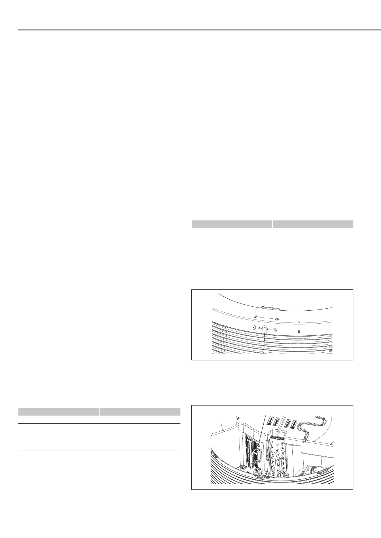
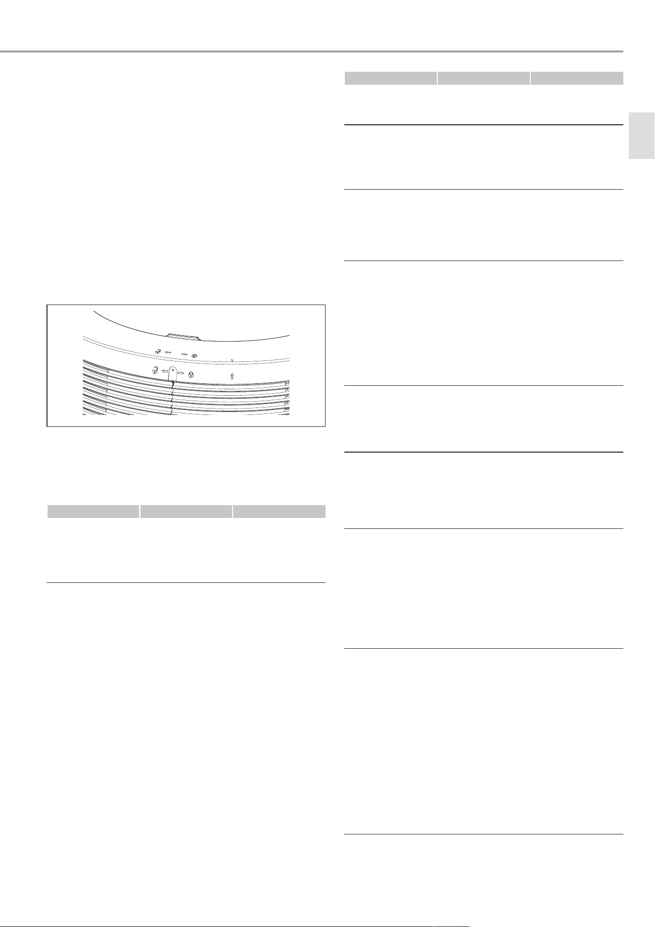
u If required due to the local conditions, secure the appliance
against tipping over in the event of an earthquake. To do
this, insert metal straps through the feed-through behind
the control panel.
D0000117569_L
7.3 Water connection
ü The electrical conductivity of the DHW is within the limits
specified to ensure cathodic corrosion protection (see
chapter
Data table [}29]
).
ü The cold water line is made from galvanised steel, stainless
steel, copper or plastic.
ü The DHW line is made from stainless steel, copper or
plastic.
u Unscrew the plastic covers from the connections for the wa-
ter lines. Leave the sealing plugs in the connections.
u NOTICE:Foreign bodies, such as welding pearls, rust or
sealing material, can impair the operational reliability of
the appliance. Flush the pipework thoroughly.
u Ensure that the water is free of contaminants.
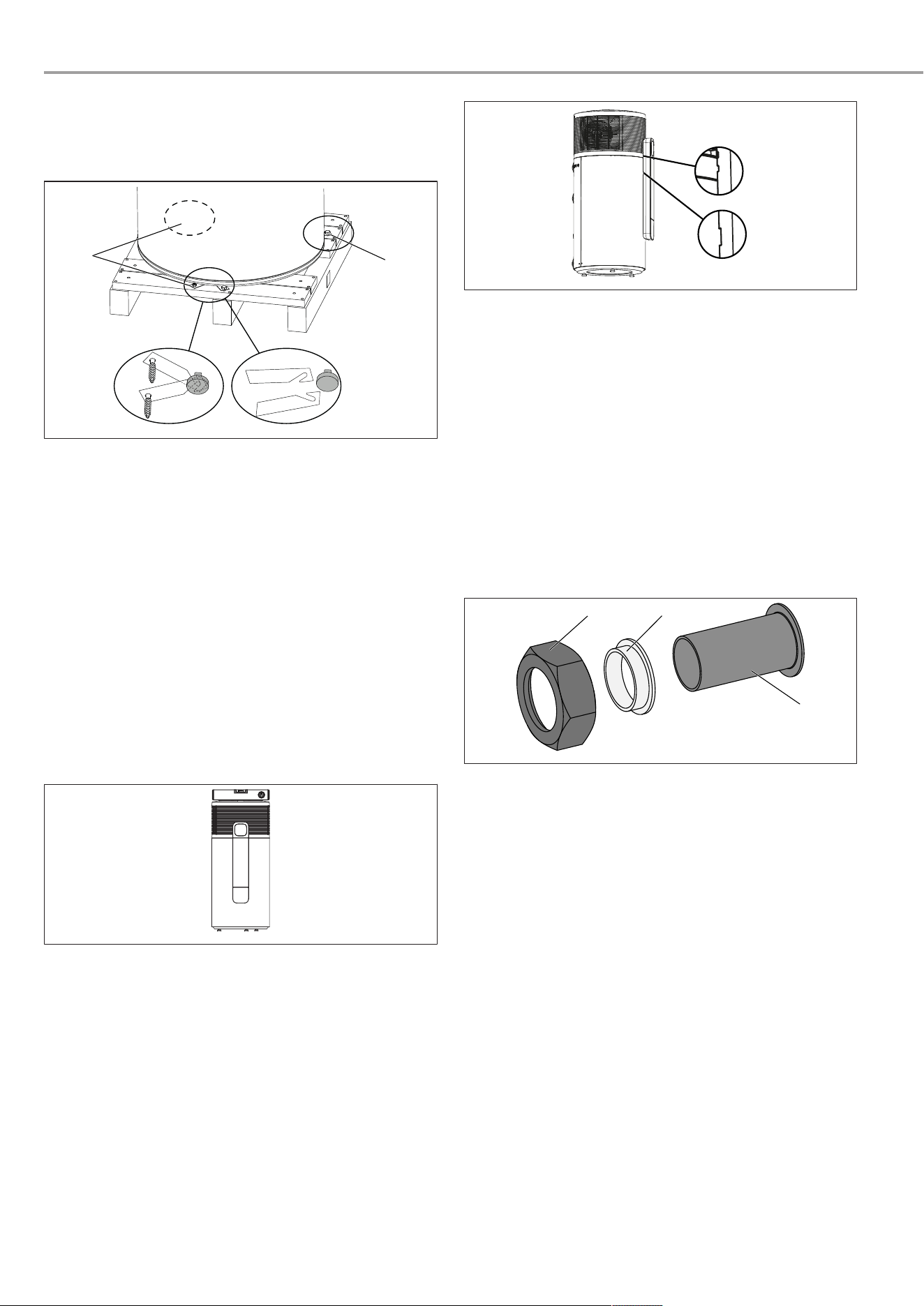
1
2
3
D0000057018
1 Union nut (G1) 2 insulating sleeve
3 Flanged pipe (22x1 mm,
copper)
u NOTICE:To protect against corrosion, make the water con-
nection using flat gaskets. Do not use hemp on the connec-
tions. Connect the supplied pipes to the cold water inlet
(c01) and the DHW outlet (c06). Use the insulating sleeves
and union nuts for this purpose.
u Insulate the water connections to reduce heat loss and con-
densation.
u Install a temperature and pressure relief valve.
u Install a cold water expansion valve if this is required by
local regulations.
Commissioning (qualified contractors)
www.stiebel-eltron.com SHP-O Plus | 11
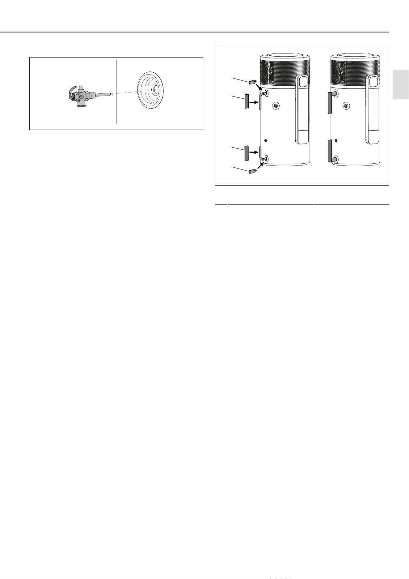
Temperature and pressure relief valve
D0000117570
u Size the drain pipe so that water can drain off unimpeded
when the temperature and pressure relief valve is fully
opened.
u Hot expansion water escapes from the temperature and
pressure relief valve. Ensure that expansion water can drip
into a drain, e.g. a tank, funnel or tundish.
u Ensure that the drain pipe of the temperature and pressure
relief valve is open to the atmosphere.
u Route the drain pipe of the temperature and pressure relief
valve with a constant fall in a room free from the risk of
frost.
u Install a temperature and pressure relief valve (850kPa) at
connection c13.
Cold water expansion valve
u Size the drain pipe so that water can drain off unimpeded
when the cold water expansion valve is fully opened.
u Ensure that the drain pipe of the cold water expansion valve
is open to the outside.
u Lay the drain pipe of the cold water expansion valve with a
constant fall in a room free from the risk of frost.
u Expansion water is discharged from the cold water expan-
sion valve. Make sure that expansion water can drip into a
drain, e.g. a tank or funnel.
u Install a cold water expansion valve (700kPa) in the cold
water inlet if this is required by local regulations.
Pressure reducing valve
u The maximum pressure in the cold water inlet must be at
least 20% below the response pressure of all safety valves.
If the maximum pressure in the cold water inlet is higher,
install a pressure reducing valve.
u If a cold water expansion valve is installed, set the pressure
reducing valve to 500kPa.
u If a cold water expansion valve is not installed, set the pres-
sure reducing valve to 700kPa.
Thermal insulation
u Insulate the DHW line and the valves in accordance with AS/
NZS 3500.4. Use the insulation supplied for this purpose.
u Insulate the cold water inlet to prevent condensate forming.
Use the insulation supplied for this purpose.
u Insulate the temperature and pressure relief valve with an
insulating jacket (or similar).
u Insulate the adaptors for the cold water inlet and DHW out-
let.
1
2
2
1
D0000117736
1 Insulation (included in the
standard delivery)
2 Insulation (not part of the
standard delivery)
u Ensure that the insulation is in contact with the DHW cylin-
der. If necessary, shorten the insulation.
Temperature limiter
u If necessary, install a temperature limiter in the DHW outlet,
e.g. a tempering valve or thermostatic mixing valve.
7.4 Condensate drain
ü The diameter of the condensate drain hose is larger than
the diameter of the condensate drain bend.
u Connect the condensate drain bend to the connection for
the condensate drain (d45).
u Connect a condensate drain hose to the condensate drain
bend.
8 Commissioning (qualified contract-
ors)
u If the appliance has been stored or transported horizontally,
leave it to rest in an upright position for at least one hour
before commissioning.
8.1 Filling the DHW cylinder
u To vent the pipework, open all hot water draw-off points
and the shut-off valve in the cold water inlet.
u As soon as water comes out without any bubbles, close the
hot water draw-off points.
u Open the temperature and pressure relief valve until water
escapes.
u If installed, open the cold water expansion valve.
8.2 Electrical connection
ü The DHW cylinder is filled.
u Install safety equipment that allows the appliance to be
separated from the power supply over an isolating distance
of 3mm. Safety equipment includes contactors, circuit
breakers and MCBs/fuses.
u Install a residual current device (RCD).
en
Commissioning (qualified contractors)
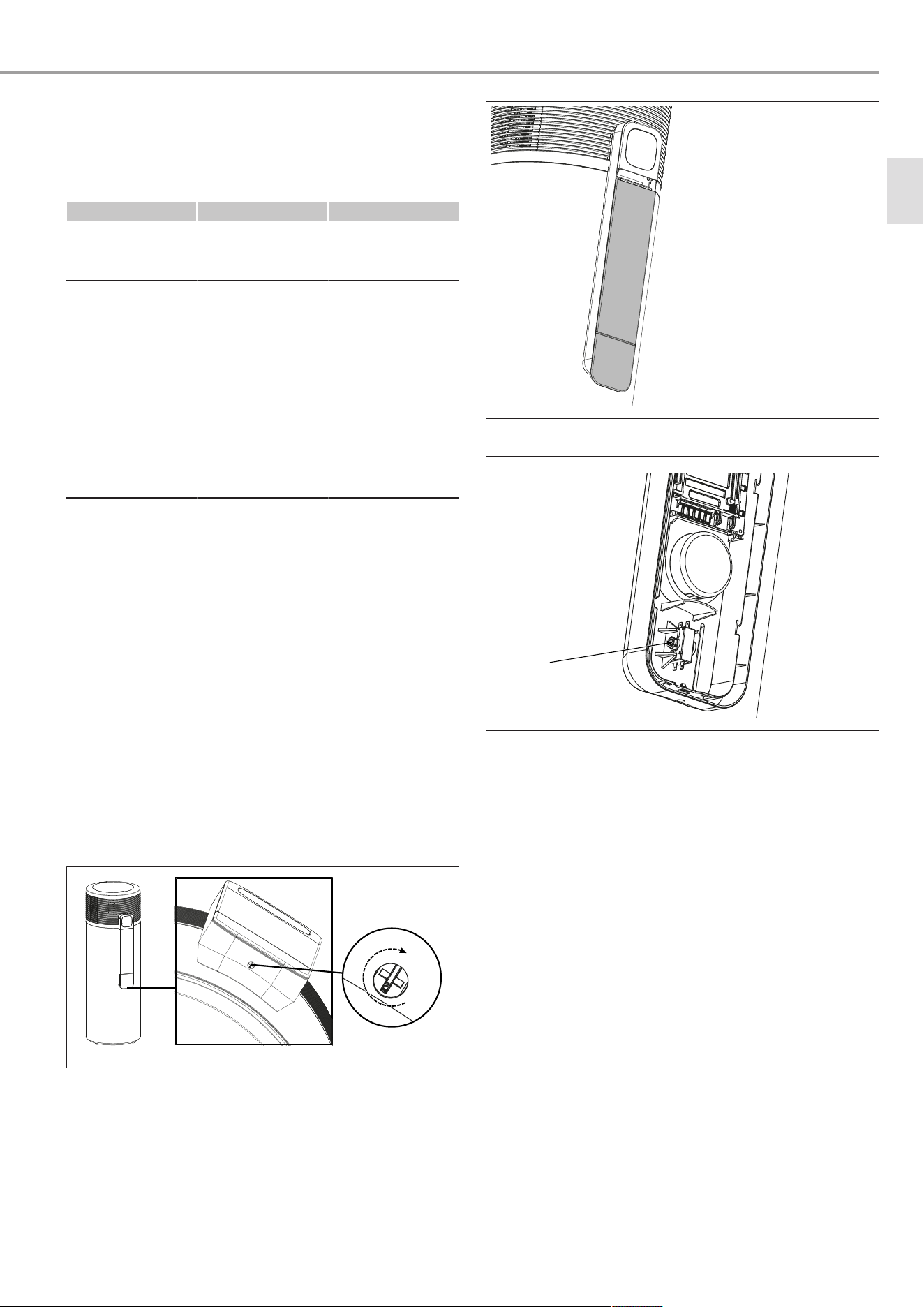
12 | SHP-O Plus www.stiebel-eltron.com
D0000117573
u Release the lock on the underside of the control panel.
u Push the control panel cover down slightly and remove it.
D0000117735
u If the power cable is too short, proceed as follows:
– Disconnect the power cable in the appliance.
– Extend or replace it with a longer power cable.
– Route the power cable through the cable grommet such
that it is watertight.
u Connect the appliance as described in the following
chapter.
8.2.1 Standard connection without external signal transmitter
The appliance is supplied from the factory without a mains plug.
u Connect the power cables according to the following dia-
gram.
XD20
XD14
GNYE
BU
BN
N
PE
L
L N PE 1 2
1 N 2
D0000117748
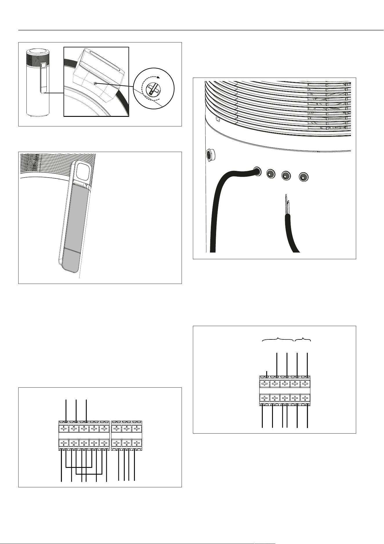
8.2.2 Connection variant: Operation with external switching
device that interrupts appliance power supply
u Prepare the electric cables in such a way that each cable
terminates with a wire ferrule.
D0000120910
u Push the cables through one of the cable entries (b01) in
the appliance casing.
u Route cables and leads through the strain relief fittings.
u Remove the jumper which leads from XD20/N to XD20/2 in
the delivered condition.
u Remove the jumper which leads from XD20/L to XD20/1 in
the delivered condition.
XD20
GNYE
BN
BU
B
N
PE
L1/
L2/
L3
L
N
A
L N PE 1 2
D0000117744
A Power supply provided by power supply utility or energy
management system for switching the load (com-
pressor)
B Power supply for the electronics
Minimum runtime and minimum pause time
When operating with external switching devices that can inter-
rupt the power supply to the appliance, such as time switches,
energy management systems or home automation systems, the
following conditions must be adhered to:
– The minimum runtime is 20minutes.
Commissioning (qualified contractors)
www.stiebel-eltron.com SHP-O Plus | 13
– The minimum pause time following a shutdown is
20minutes.
– Do not switch the appliance on or off more than 10times a
day using an external switching device.
– The contact load capacity of the switching actuator must
satisfy the fuse protection requirements according to the
data table.
Closing and locking the control panel
u Replace the control panel cover.
u Lock the control panel.
8.2.3 Connection variant: Operation with external signal
transmitter
Set temperature1 is the standard set temperature.
Set temperature2 is preset but inactive. If an external switching
signal is present for at least one minute, set temperature 2 is
activated and is valid for at least 20minutes.
As long as the external switching signal is present, set temper-
ature2 remains active.
The compressor switches off when the external switching signal
is cancelled or the selected set temperature is reached. The
compressor remains switched off for a minimum idle time of
20minutes. Afterwards, the selected set temperature1 becomes
higher ranking again.
Example:
– Water temperature = 55°C
– Set temperature1 = 50°C
– Set temperature2 = 65°C
A
1
0
0 5 10 15 20 25 30 35 40 45 50 55 60 65 70 75 t [min]
B
1
1
0 2
0 5 10 15 20 25
30
35 40 45 50 55 60 65 70 75 t [min]
D0000034613
A External signal
B Compressor
1 20min. minimum runtime, set temperature2
2 20min. minimum compressor pause time
SG Ready
"SGReady" is a trademark of the Bundesverband Wärmepumpe
e.V. (German Heat Pump Association) and denotes a property of
heat pumps whose control technology enables them to be integ-
rated into a smart power grid (SG = Smart Grid).
D0000043557
The device has two contact inputs (input 1 = XD14/1, input 2 =
XD14/2) for coupling to an inverter or a ripple control receiver.
This enables you to integrate your connected heat pump into an
intelligent power supply. Alternatively, you can utilise the device
to increase the proportion of self-generated photovoltaic power.
Depending on the switching, your device can execute the follow-
ing operating modes:
SG Ready Status1 (operating state 1)
– Input 1 = XD14/1, input 2 = XD14/2
– Switch input 1 = 0, switch input 2 = 1
– Voltage between XD14/2 and XD14/N
– Standby temperatures as specified in the operating and in-
stallation instructions for the connected heat pump
(standby).
– Frost protection is assured.
– The "Standby" symbol flashes slowly.
SG Ready Status2 (operating state 2)
– Input 1 = XD14/1, input 2 = XD14/2
– Switch input 1 = 0, switch input 2 = 0
– Automatic/ Programmed mode as specified in the operat-
ing and installation instructions for the connected heat
pump.
SG Ready Status3 (operating state 3)
– Input 1 = XD14/1, input 2 = XD14/2
– Switch input 1 = 1, switch input 2 = 0
– Voltage between XD14/1 and XD14/N
– Forced operation with increased value for the DHW temper-
ature (set temperature 2) (configuration in the MyStiebel
app).
SG Ready Status4 (operating state 4)
– Input 1 = XD14/1, input 2 = XD14/2
– Switch input 1 = 1, switch input 2 = 1
– Voltage between XD14/1 and XD14/N and voltage between
XD14/2 and XD14/N
– Immediate control of the maximum value (fixed) for the
DHW temperature (set temperature 2) including operation
of electric emergency/auxiliary heater (configuration in the
MyStiebel app)
An energy management system or the power supply utility (PSU)
can control the cited operating states, e.g.for load redistribu-
tion in the event of a power shortage.
If SG Ready status 1 or 4 is active, the symbol for the "SG Ready"
function flashes on the appliance.
When SG Ready Status 3 is activate, the symbol for the "SG
Ready" function lights up on the appliance.
Connecting an external signal transmitter
In order to control the appliance using an external signal, you
must connect a separate electric cable inside the appliance.
en
Commissioning (qualified contractors)
14 | SHP-O Plus www.stiebel-eltron.com
D0000120910
u Push the cables through one of the cable entries (b01) in
the appliance casing.
u Route cables and leads through the strain relief fittings.
u NOTICE:If the voltage is too high this can damage the ap-
pliance. Observe the permissible voltage range for external
signal transmitters.
u The table shows which terminals you need to connect to be
able to map the required SG Ready status.
Terminal assignment [XD14] Status
2 + N SG1
no connection SG2
1 + N SG3
1 + N + 2 SG4
Example1: Switch-on signal with separate phase supply
XD20
XD14
GNYE
BU
BN
N
PE
L
N
L
EVU
L N PE 1 2 1 N 2
D0000117745
EVU
(PSU)
Signal from the power supply utility
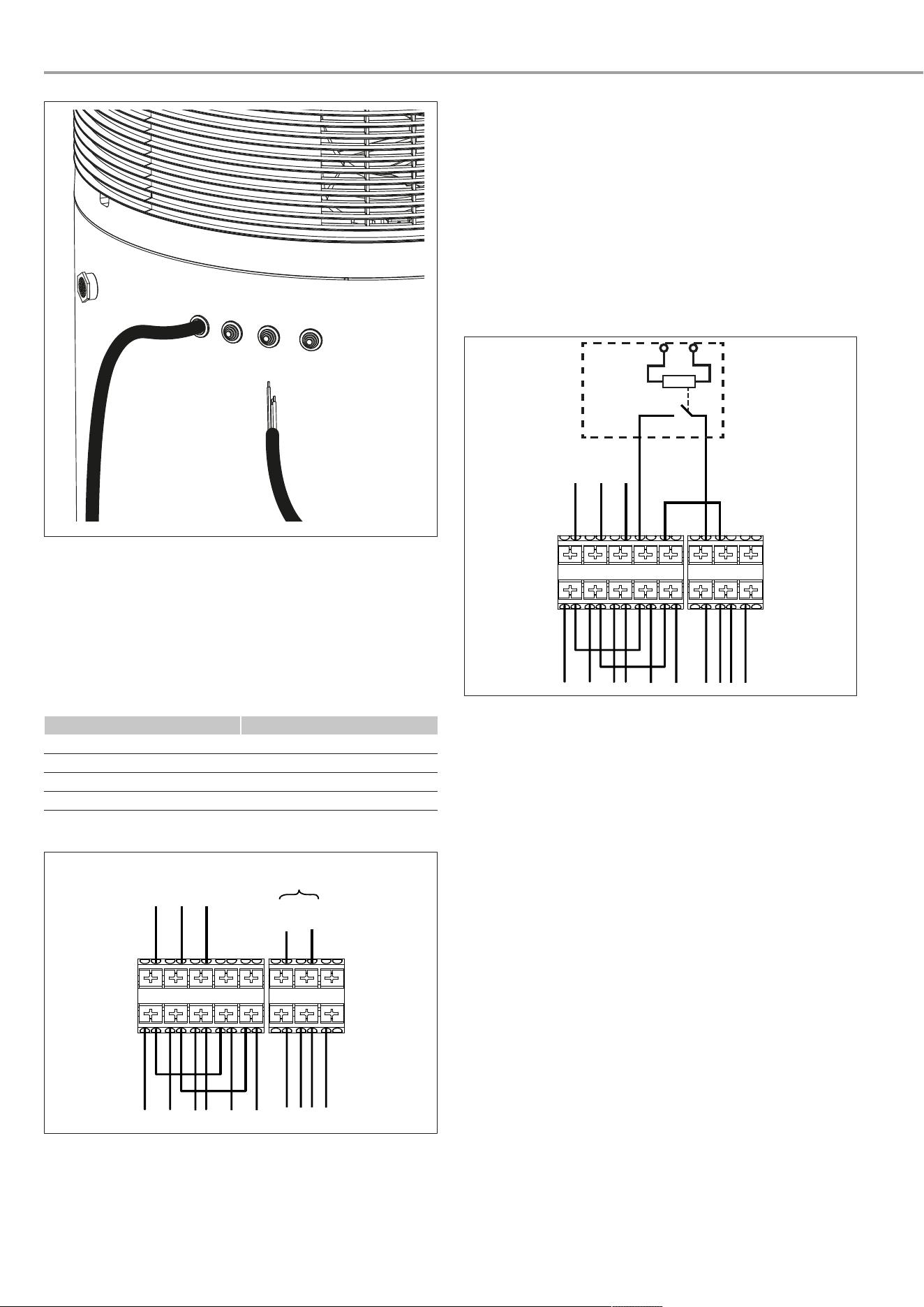
Example2: Photovoltaic signal via on-site relay and phase
routed outside the appliance
The relay in the inverter or photovoltaic system must meet the
following requirements:
– Potential-free relay (240VAC, 1A) with N/O contact
– Adherence to safety regulations and standards for safety ex-
tra low voltage
– The switching output must be programmed such that the
relay closes or opens if certain limits are exceeded or un-
dershot (e.g.inverter output level, feed-in to the power
grid).
SG Ready Status 3 is activated via the photovoltaic signal.
XD20
XD14
1
GNYE
BU
BN
N
PE
L
1 N 2L N PE 1 2
D0000117746
1 Inverter (floating contact)
The inverter power feed is usually located at a central distribu-
tion point (e.g. in the main fuse box).
Closing and locking the control panel
u Replace the control panel cover.
u Lock the control panel.
8.3 Initial start-up
u Switch the mains power supply on.
u Check whether the heat pump heats the water.
ð During the heat-up process, expansion water will drip
from the safety valve.
8.4 Recommissioning
If the heat pump is switched off by an interruption to the power
supply and the power supply is subsequently restored, no meas-
ures are required to restart it.
Following an interruption to the power supply, compressor op-
eration remains blocked for at least one minute. The control
delays the electrical start-up by one minute, during which the
appliance initialises. If the compressor subsequently fails to
start, it may be locked out by additional safety devices (motor
overload relay and high pressure switch). This block should lift
after 1to 10minutes.
The heat pump will have saved the parameters most recently set
and will continue operating with them.
Operation
www.stiebel-eltron.com SHP-O Plus | 15
9 Operation
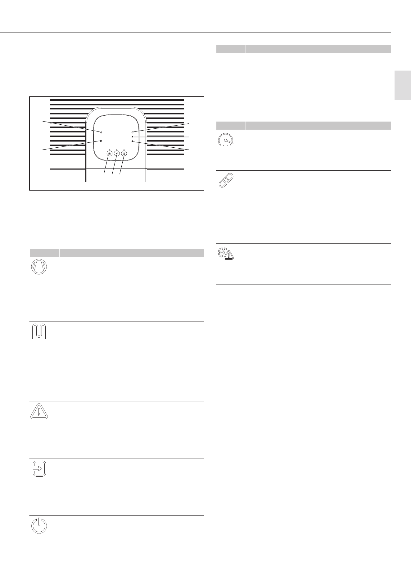
9.1 Display and controls
The appliance can be operated via an app and the buttons on
the appliance.
3 4 5
1
2 6
7
8
D0000117715
1 Standby 2 SG Ready
3 "Emergency mode" button 4 "Pairing" button
5 "Rapid heat-up" button 6 Fault
7 Electric emergency/auxili-
ary heater
8 Compressor
Symbols
Symbol Meaning
Compressor
– Off
No heating demand to the compressor
– Flashing
Heating demand to the compressor, but the
compressor is not (yet) active
– On
Compressor active
Electric emergency/auxiliary heater
– Off
No heating demand to the electric emergency/
auxiliary heater
– Flashing
Heating demand to the electric emergency/aux-
iliary heater, but the electric emergency/auxili-
ary heater is not (yet) active
– On
Electric emergency/auxiliary heater active
Fault
– Off
No fault
– Flashing
See chapter
Troubleshooting [}17]
.
– On
See chapter
Troubleshooting [}17]
.
SG Ready
– Off
No external signal
– On
SG Ready status 3 active
– Flashing
SG Ready status 1 or 4 active
Standby
– Off
Appliance active, frost protection guaranteed
Symbol Meaning
– Flashing slowly
Frost protection active, SG Ready function active
– Flashing rapidly
Load shedding
– On
Frost protection active
LED
Button Meaning
Rapid heat-up
– Off
Rapid heat-up inactive
– On
Rapid heat-up active
Pairing
– Off
WLAN function inactive
– Flashing slowly
Access point mode requested
– Flashing rapidly
Access point mode active
– On
WLAN connection established
Emergency mode
– Off
Emergency mode inactive
– Flashing
Emergency mode active
Keypad lock
u The keypad lock can be activated and deactivated via the
app.
9.2 Pairing the heat pump with the app
ü Secure Wi-Fi® network (802.11b/g/n/ 2.4GHz, DHCP)
ü Supported encryption methods: WPA™ PSK, WPA2™ PSK,
WPA3™ PSK
ü Internet connection to the mobile device
ü Location sharing of the mobile device active
ü Operating system of the mobile device: iOS® version 12.0 or
higher, Android® version 8.0 or higher
ü The requirements specified in the App Store® or Google
Play Store™ for installing and using the app are satisfied
ü Mobile device no more than 3m away from the heat pump
during pairing
ü Proof of competence from the specialist company is re-
quired for the Servicewelt app for qualified contractors
u Download the app to your mobile device from the Apple
App Store® or Google Play Store™.
– App for qualified contractors: Servicewelt app
– App for operators: MyStiebel app
u Register in the app. (Servicewelt app: If you have Ser-
vicewelt login credentials, you can use these here)
u Grant the app the necessary authorisations.
u Add a new appliance in the app and follow the instructions.
en
Settings
16 | SHP-O Plus www.stiebel-eltron.com
After the appliance has been successfully integrated into the
network, communication between the appliance and the mobile
end device may be restricted for several minutes. If this occurs,
it does not indicate an error; any necessary software updates for
the WLAN adaptor are downloaded and installed first.
Servicewelt app: Some functions of the app are not available
until the specialist company has provided proof of competence.
9.3 Activating/deactivating rapid heat-up
Application
– One-off demand for extra hot water
Activating rapid heat-up on the programming unit
ü Keypad lock is inactive.
u Press the "Rapid heat-up" button for 2seconds.
ð The "heat pump" and "electric emergency/auxiliary heater"
symbols are shown until the function has ended. The heat
pump and electric emergency/auxiliary heater are started
once in parallel operation.
ð When the water temperature rises by a hysteresis value
above the set temperature at the cylinder top sensor, the
electric emergency/auxiliary heater is switched off (rapid
heat-up). The electric emergency/auxiliary heater remains
in standby mode until the set temperature has been
reached throughout the DHW cylinder (comfort heat-up). A
flashing "electric emergency/auxiliary heater" symbol indic-
ates that the electric emergency/auxiliary heater is in
standby mode.
Deactivating rapid heat-up on the programming unit
ü Keypad lock is inactive.
u To end the function prematurely, press the "Rapid heat-up"
button for 2seconds.
Activating and deactivating rapid heat-up in the MyStiebel app
u Activate the function in the app.
u If you want to end the function prematurely, deactivate the
function in the app.
10 Settings
Implement the required settings in the respective app:
– App for qualified contractors: Servicewelt app
– App for operators: MyStiebel app
11 Cleaning
You may only use the specified cleaning agents.
Component Interval
Casing As required
Air intake grille
Air outlet grille
As required, every 6months
Adapt the interval according to
the air quality and the installa-
tion conditions.
Condensate drain As required, for the first time
after 1year
Adapt the interval according to
the installation conditions.
Taps
Safety valve
As required
11.1 Cleaning the casing top
u Clean the casing top with a cloth moistened with water.
11.2 Cleaning the condensate drain
u Remove the condensate drain bend.
u Remove any dirt from the connection for the condensate
drain.
11.3 Dissolving scale build-up
Almost every type of water will deposit limescale at high tem-
peratures. Limescale will settle inside the product and affect its
function and service life.
A qualified contractor who is aware of the local water quality
will tell you when the next descaling is due.
u Check the taps regularly. Use commercially available de-
scaling agents to remove limescale from the tap spouts.
u Regularly activate the safety valve to prevent it from becom-
ing blocked, e.g.by limescale deposits.
12 Cleaning (qualified contractors)
You may only use the specified cleaning agents.
Component Interval
Evaporator As required, for the first time
after 1year
Adapt the interval according to
the air quality and installation
conditions.
12.1 Cleaning the evaporator
u Isolate the appliance from the power supply.
D0000117580
u Undo the screw at the back of the casing cover.
u To do this, turn the casing cover clockwise.
u Remove the casing cover.
u Remove the front insulation.
1
D0000120795
1 Insulation material screw
Troubleshooting
www.stiebel-eltron.com SHP-O Plus | 17
u Remove the insulation material screw before removing the
insulation on the air discharge side.
u Remove the insulation on the air intake side.
u WARNING:The sharp-edged fins of the evaporator can
cause injury. Wear protective gloves. Clean the evaporator
fins with water and a soft brush.
u Fit the insulation on the air intake side. Ensure that the
temperature sensor protrudes 40mm from the insulation.
u Fit the insulation on the air discharge side.
u Secure the insulation on the air discharge side with the in-
sulation material screw.
u Fit the front insulation.
u Place the casing cover on the appliance.
u Turn the casing cover anti-clockwise so that it latches in
place.
D0000117580
u Tighten the screw at the back of the casing cover.
13 Troubleshooting
u Please also observe the notifications in the MyStiebel app.
Fault Possible cause Remedy
The appliance does
not supply hot wa-
ter.
The appliance has
no power.
u Check that the
appliance is
connected to
the power sup-
ply.
The appliance does
not supply hot wa-
ter.
A fuse/MCB in the
distribution board
has blown/tripped.
u Check whether
the fuses/MCBs
in the distribu-
tion board have
blown/tripped.
u If necessary,
isolate the ap-
pliance from the
power supply.
u Reconnect the
appliance to the
power supply.
u Replace the
fuses/reset the
MCBs.
u Contact a quali-
fied contractor if
the fuse/MCB
blows/trips
again after the
appliance is
Fault Possible cause Remedy
connected to
the power sup-
ply.
The appliance does
not supply hot wa-
ter.
The air intake grille
or air outlet grille is
blocked.
u Remove dirt or
other blockages
to ensure clear
intake and out-
let air flows.
The appliance does
not supply a suffi-
cient quantity of
DHW.
Below the applica-
tion limit of the heat
pump (compressor),
DHW heating is
taken over by the
electric emergency/
auxiliary heater.
No action required
The appliance does
not supply hot water
or the "compressor"
symbol is flashing.
The temperature of
the intake air is out-
side the application
limits. The com-
pressor was
switched off/locked
automatically.
No action required
The appliance heats
the water using the
electric emergency/
auxiliary heater. As
soon as the temper-
ature is back within
the application lim-
its, the heating pro-
cess is continued
with the com-
pressor.
The appliance does
not supply hot wa-
ter.
Hot water was re-
cently drawn off and
the appliance has
not yet been able to
reheat the water in
the DHW cylinder.
No action required
u Let the appli-
ance complete
the heat-up
process.
The safety valve of
the DHW cylinder is
dripping.
The appliance cylin-
der is at mains wa-
ter pressure. During
heat-up, expansion
water may drip from
the safety valve.
u If water contin-
ues to drip after
heat-up has
stopped, inform
a qualified con-
tractor.
The condensate
drain drips.
The surface temper-
ature of the evapor-
ator is lower than
the dew point tem-
perature of the am-
bient air. This res-
ults in condensate
forming. The
amount of condens-
ate depends on the
humidity level of the
ambient air.
No action required
The "fault" symbol is
continuously illu-
minated.
Category3 faults A continuously illu-
minated "fault" sym-
bol indicates that a
fault has occurred,
but the appliance is
heating neverthe-
less.
u Notify a quali-
fied contractor.
The qualified
contractor can
find more in-
formation on
troubleshooting
in the Ser-
vicewelt app.
The "fault" symbol
flashes.
The compressor is
locked out.
A flashing "fault"
symbol indicates
that a fault has oc-
en
Troubleshooting
18 | SHP-O Plus www.stiebel-eltron.com
Fault Possible cause Remedy
curred, but the ap-
pliance is heating
nevertheless.
u Notify a quali-
fied contractor.
The qualified
contractor can
find more in-
formation on
troubleshooting
in the Ser-
vicewelt app.
The compressor is
switched off; the fan
continues to run.
The "compressor"
symbol is shown.
The appliance is in
defrost mode.
No action required
The "compressor"
symbol is flashing.
There is a heat de-
mand, but the com-
pressor is locked
out.
No action required
The compressor re-
starts automatically
after the compressor
lockout time has
elapsed. The symbol
stops flashing auto-
matically.
The "electric emer-
gency/auxiliary
heater" symbol is
flashing.
A temperature con-
troller has switched
off the electric
emergency/auxiliary
heater during rapid
heat-up.
No action required
The appliance con-
tinues the rapid
heat-up process us-
ing the heat pump.
When the controller
enables the electric
emergency/auxiliary
heater again, the
symbol stops flash-
ing. The symbol
goes out when the
temperature
throughout the DHW
cylinder reaches the
set rapid heat-up
temperature.
The "electric emer-
gency/auxiliary
heater" symbol is il-
luminated but the
electric emergency/
auxiliary heater is
not active.
The electric emer-
gency/auxiliary
heater lights up
when there is a de-
mand. The internal
controller of the
electric emergency/
auxiliary heater may
have ended electric
heating. A possible
cause may be a fault
in the electric emer-
gency/auxiliary
heater. A possible
cause may be that
the high limit safety
cut-out has respon-
ded.
u Notify a quali-
fied contractor.
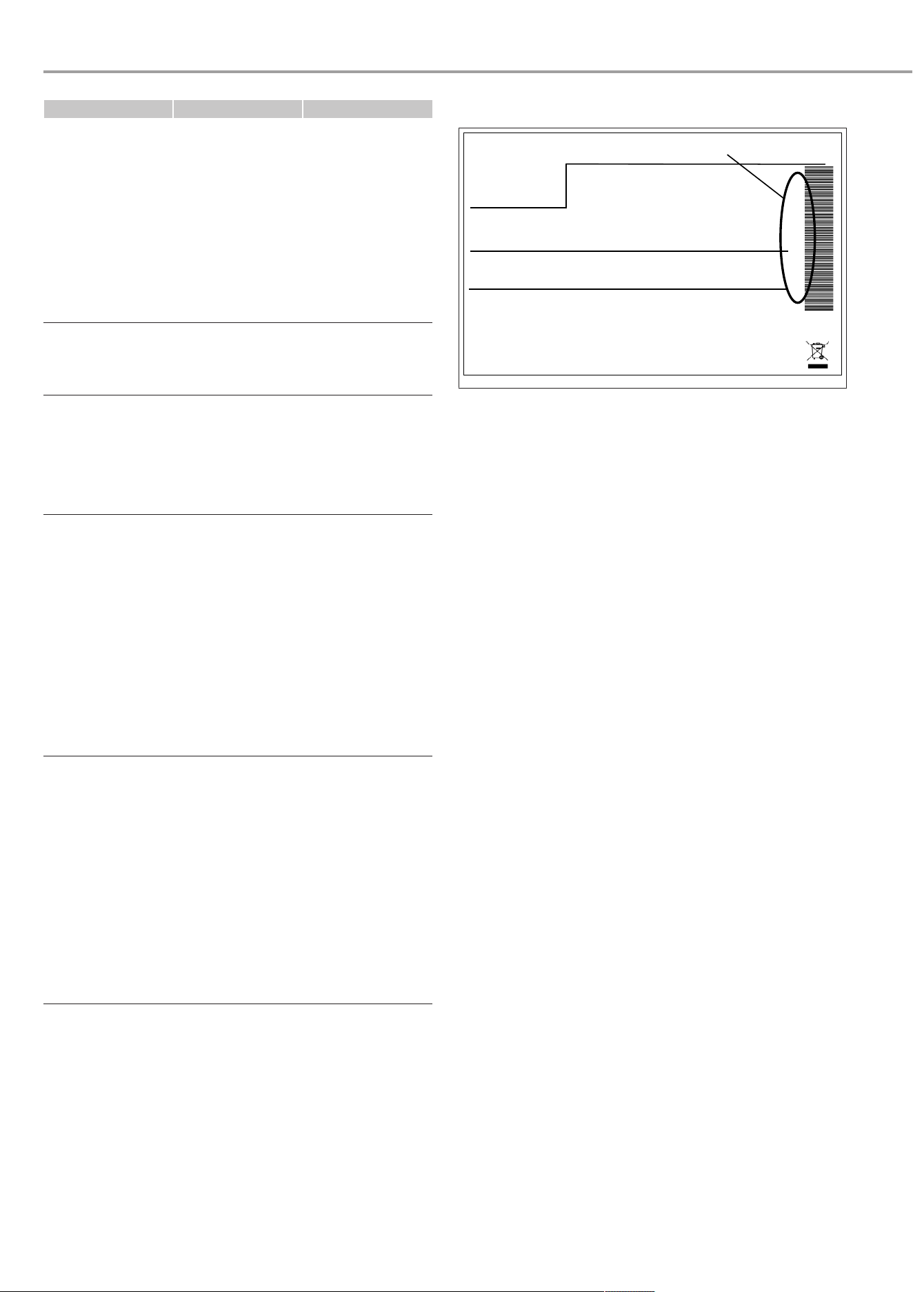
u If you cannot remedy the fault, contact STIEBEL ELTRON.
u To facilitate and speed up your enquiry, please provide
STIEBEL ELTRON with the number from the type plate.
The type plate is located next to the power cable.
Example type plate
Montageanweisung beachten! Dichtheit geprüft!
Made in Germany
*xxxxxxxxxxxxxxxxxx*
1
D0000107757
1 Number on the type plate
13.1 Activating/deactivating emergency heating
mode
Activating emergency heating mode
ü Keypad lock is inactive.
u Press the "Emergency mode" button on the programming
unit for 2seconds. Alternatively, activate emergency mode
in the MyStiebel app.
ð The current set temperature is ignored. In emergency
heating mode, the appliance operates with a fixed set
temperature. In the upper cylinder section, the DHW is
heated up to 65°C by the electric emergency/auxiliary
heater.
ð Emergency heating mode remains activated for 7days.
u If you want to extend emergency heating mode by a further
7days, press the "Emergency mode" button again. Alternat-
ively, extend the emergency mode time in the MyStiebel
app.
ð From this point on, emergency heating mode remains
activated for 7days.
After a power interruption
Emergency heating mode remains active after an interruption to
the power supply.
Deactivating emergency heating mode
ü Keypad lock is inactive.
u Press the "Emergency mode" button on the programming
unit for 2seconds. Alternatively, deactivate emergency
mode in the MyStiebel app.
Troubleshooting (qualified contractors)
www.stiebel-eltron.com SHP-O Plus | 19
14 Troubleshooting (qualified con-
tractors)
u Please also observe the notifications in the Servicewelt app.
Fault Possible cause Remedy
The appliance does
not supply hot wa-
ter.
The appliance has
no power. The
power cable is dam-
aged.
u Replace the
power cable.
The compressor is
no longer working.
The motor overload
relay has responded
because the temper-
ature or current was
too high for the
compressor.
u Eliminate the
cause that led
the motor over-
load relay to re-
spond.
ð After a short
cooling period,
the motor over-
load relay will
restart the com-
pressor auto-
matically.
The compressor is
no longer working.
There was no pres-
sure equalisation in
the refrigerant cir-
cuit, so the com-
pressor is operating
against a high pres-
sure.
The electronic ex-
pansion valve is
faulty.
u Start a calibra-
tion run in the
Servicewelt app.
Alternatively:
u Isolate the ap-
pliance from the
power supply.
u Reconnect the
power supply.
14.1 Resetting the high limit safety cut-out
If the temperature of the cylinder water exceeds 89°C, the high
limit safety cut-out switches off the electric emergency/auxiliary
heater. These high temperatures can be caused by a defective
heating element or a fault in the electronics, for example.
The high limit safety cut-out also responds in the event of frost.
u Remove the cause of the fault.
u Isolate the appliance from the power supply.
D0000117573
u Release the lock on the underside of the control panel.
u Push the control panel cover down slightly and remove it.
D0000117735
u Press the reset button on the safety cut-out.
D0000117576
u If the high limit safety cut-out cannot be reset, replace it.
u Replace the control panel cover.
u Lock the control panel.
u Reconnect the appliance to the power supply.
14.2 Safety pressure limiter
If the pressure in the refrigerant circuit is too high, the safety
pressure limiter interrupts the power supply to the compressor
until the pressure in the refrigerant circuit falls below the set
limit value. If the safety pressure limiter responds 5 times in
5hours, compressor operation is blocked.
u Remove the cause of the fault.
ð The appliance carries out pressure equalisation. This
process takes a few seconds.
u When the pressure equalisation process is complete, unlock
the heat pump in the Servicewelt app.
en
Maintenance (qualified contractors)
20 | SHP-O Plus www.stiebel-eltron.com
15 Maintenance (qualified contractors)
You may only carry out maintenance work as described here.
Component Activity Interval
Electric emergency/
auxiliary heater
Descale the emer-
gency/auxiliary
heater to increase
its service life.
For the first time
after 1year
As required
If necessary, shorten
the interval depend-
ing on the water
quality and the in-
stallation conditions.
Condensate drain Check that the con-
densate drain is
clear.
For the first time
after 1year
As required
If necessary, shorten
the interval depend-
ing on the installa-
tion conditions.
Evaporator Check the evapor-
ator.
For the first time
after 1year
As required
If necessary, shorten
the interval depend-
ing on the air qual-
ity and the installa-
tion conditions.
Valves (safety valve,
pressure reducing
valve, drain valve)
Check the valves for
limescale deposits
and damage.
For the first time
after 1year
As required
If necessary, shorten
the interval depend-
ing on the water
quality and the in-
stallation conditions.
Signal anode Check the consump-
tion indicator.
For the first time
after 2years
As required
If necessary, shorten
the interval depend-
ing on the water
quality and degree
of wear.
15.1 Descaling the electric emergency/auxiliary
heater
u Isolate the appliance from the power supply.
u Empty the DHW cylinder to below the flange for the electric
emergency/auxiliary heater (>130litres) (see chapter
Draining the DHW cylinder [}22]
).
D0000117573
u Release the lock on the underside of the control panel.
u Push the control panel cover down slightly and remove it.
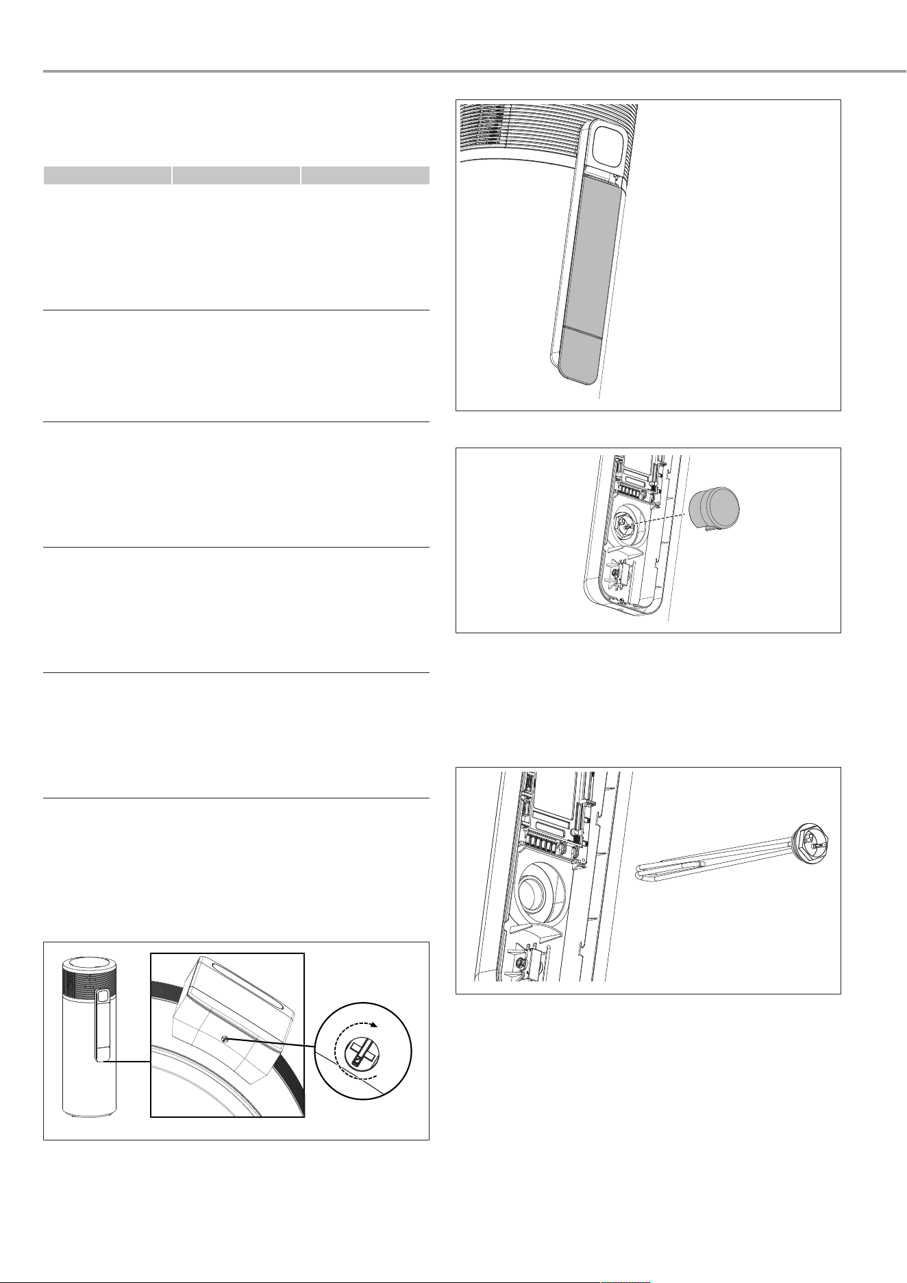
D0000117735
u Remove the insulation from the emergency/auxiliary heater.
D0000117577
u Disconnect the electrical connection to the emergency/aux-
iliary heater.
u Remove the sensor bulb of the high limit safety cut-out from
the sensor pocket.
u Unscrew the emergency/auxiliary heater from the cylinder
connection piece.
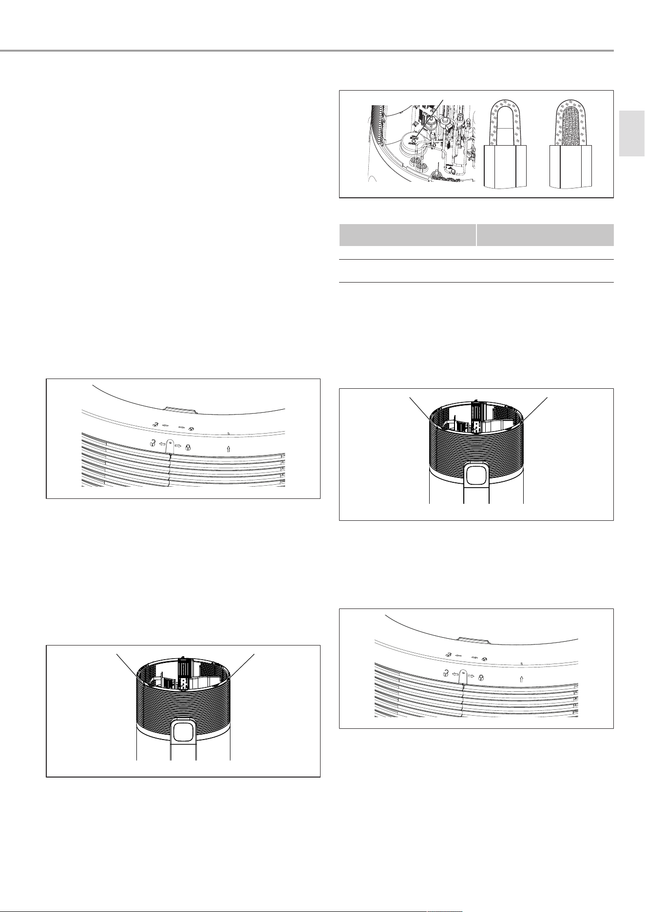
D0000117578
u Descale the heating element with a brush.
u Screw the emergency/auxiliary heater into the tank connec-
tion piece with the notch pointing upwards.
u Refill the DHW cylinder (see chapter
Filling the DHW cylin-
der [}11]
).
u Check the leak-tightness of the electric emergency/auxiliary
heater.
u Push the sensor bulb of the high limit safety cut-out into the
sensor pocket.
u Re-establish the electrical connection of the emergency/
auxiliary heater.
Maintenance (qualified contractors)
www.stiebel-eltron.com SHP-O Plus | 21
u Fit the insulation on the emergency/auxiliary heater.
u Replace the control panel cover.
u Lock the control panel.
u Reconnect the appliance to the power supply.
15.2 Checking valves
u Regularly check the valves in the system to ensure the oper-
ational reliability of the appliance. The amount of limescale
deposits depends on the local water quality.
The following valves should be included in the check:
– Temperature and pressure relief valve
– Pressure reducing valve
– Cold water expansion valve
u Check that the valves are not scaled up or damaged.
u Remove any limescale deposits.
u Replace any faulty valves. Use valves recommended by us.
u Check the function of the valves.
15.3 Checking consumption indicator on signal
anode
u Isolate the appliance from the power supply.
D0000117580
u Undo the screw at the back of the casing cover.
u To do this, turn the casing cover clockwise.
u Remove the casing cover.
u Remove the front insulation.
Removing the side casing (only if the ceiling height is
insufficient)
If the ceiling height does not provide sufficient working space,
carry out the steps in this chapter. Otherwise, continue with the
steps in the following chapter.
D0000117581_L
u Undo the screws on the side casing.
u Lift up and remove the front side casing from the guide rail.
Checking consumption indicator on signal anode
1
D0000120794
1 Signal anode
Consumption indicator col-
our
Meaning
white Signal anode OK
Red Signal anode depleted, re-
placement necessary
u Check the consumption indicator of the signal anode.
u Replace the signal anode if it is depleted. For this, ensure
there is a good connection between the signal anode and
the DHW cylinder (maximum transition resistance 0.3Ω).
Installing the side casing
u Insert the front side casing in the guide rail.
D0000117581_L
u Screw the side casing tight.
u Fit the front insulation.
u Place the casing cover on the appliance.
u Turn the casing cover anti-clockwise so that it latches in
place.
D0000117580
u Tighten the screw at the back of the casing cover.
15.4 Replacing the power cable
The power cable should only be replaced by a qualified con-
tractor.
u Replace a faulty power cable with a new one.
en

Shutdown (qualified contractors)
22 | SHP-O Plus www.stiebel-eltron.com
16 Shutdown (qualified contractors)
It is only possible to switch off the appliance by interrupting the
power supply.
u Isolate the appliance from the power supply.
16.1 Draining the DHW cylinder
u Isolate the appliance from the power supply.
u Close the shut-off valve in the cold water inlet (c01).
u If there is no drain nearby, route a hose from the cold water
inlet to the drain.
u WARNING:There is a risk of scalding at outlet temperatures
in excess of 43°C. Ensure you do not come into direct con-
tact with the outflowing water or components that have
heated up.
u Disconnect the cold water supply line at the cold water in-
let.
u To vent the heat pump, disconnect the DHW line connected
to the DHW outlet (c06).
Some residual water will remain in the lower section of the
DHW cylinder.
17 Maintenance and inspection (quali-
fied contractors)
The area around the unit should be dry, clean and well ventil-
ated. Clean the heating exchanger regularly to maintain good
heat exchange and conserve energy .
The operation pressure of the refrigerant system should only be
serviced by a certified technician.
You should discharge the water at the bottom of water tank (in-
let nozzle cold water) if the unit will not be used for an extended
period of time.
You should check the unit thoroughly and fill the system with
water fully before using it for the first time after a prolonged
period of no usage.
Checks to the area
Prior to beginning work on systems containing flammable refri-
gerants, safety checks are necessary to ensure that the risk of
ignition is minimised. For repair to the refrigerating system, the
following precautions shall be complied with prior to conduct-
ing work on the system.
Work procedure
Work shall be undertaken under a controlled procedure so as to
minimise the risk of a flammable gas or vapour being present
while the work is being performed.
General work area
All maintenance staff and others working in the local area shall
be instructed on the nature of work being carried out. Work in
confined spaces shall be avoided. The area around the work-
space shall be sectioned off. Ensure that the conditions within
the area have been made safe by control of flammable material.
Checking for presence of refrigerant
The area shall be checked with an appropriate refrigerant de-
tector prior to and during work, to ensure the technician is
aware of potentially flammable atmospheres. Ensure that the
leak detection equipment being used is suitable for use with
flammable refrigerants, i.e. non-sparking, adequately sealed or
intrinsically safe.
Presence of fire extinguisher
If any hot work is to be conducted on the refrigeration equip-
ment or any associated parts, appropriate fire extinguishing
equipment shall be available to hand. Have a dry powder or CO
2
fire extinguisher adjacent to the charging area.
No ignition sources
No person carrying out work in relation to a refrigeration sys-
tem which involves exposing any pipe work that contains or has
contained flammable refrigerant shall use any sources of igni-
tion in such a manner that it may lead to the risk of fire or ex-
plosion. All possible ignition sources, including cigarette
smoking, should be kept sufficiently far away from the site of in-
stallation, repairing, removing and disposal, during which flam-
mable refrigerant can possibly be released to the surrounding
space. Prior to work taking place, the area around the equip-
ment is to be surveyed to make sure that there are no flam-
mable hazards or ignition risks. No Smoking signs shall be dis-
played.
Ventilated area
Ensure that the area is in the open or that it is adequately vent-
ilated before breaking into the system or conducting any hot
work. A degree of ventilation shall continue during the period
that the work is carried out. The ventilation should safely dis-
perse any released refrigerant and preferably expel it externally
into the atmosphere.
Checks to the area
Prior to beginning work on systems containing flammable refri-
gerants, safety checks are necessary to ensure that the risk of
ignition is minimised. For repair to the hot-water system, the
following precautions shall be complied with prior to conduct-
ing work on the system.
Checks to the refrigeration equipment
Where electrical components are being changed, they shall be
fit for the purpose and to the correct specification. At all times
STIEBEL ELTRON maintenance and service guidelines shall be
followed. If in doubt consult the STIEBEL ELTRON technical de-
partment for assistance. The following checks shall be applied to
installations using flammable refrigerants:
– The charge size is in accordance with the room size within
which the refrigerant containing parts are installed;
– Marking to the equipment continues to be visible and
legible. Markings and signs that are illegible shall be cor-
rected.
Checks to electrical devices
Repair and maintenance to electrical components shall include
initial safety checks and component inspection procedures. If a
fault exists that could compromise safety, then no electrical sup-
ply shall be connected to the circuit until it is satisfactorily dealt
with. If the fault cannot be corrected immediately but it is ne-
cessary to continue operation, an adequate temporary solution
shall be used. This shall be reported to the owner of the equip-
ment so all parties are advised.
Initial safety checks shall include:
– That capacitors are discharged: this shall be done in a safe
manner to avoid possibility of sparking;
– That there no live electrical components and wiring are ex-
posed while charging, recovering or purging the system;

Maintenance and inspection (qualified contractors)
www.stiebel-eltron.com SHP-O Plus | 23
– That there is continuity of earth bonding.
Repairs to sealed components
Sealed electrical components should not be repaired. In the
event of a fault, these components must be replaced with ori-
ginal spare parts from STIEBEL ELTRON.
Repair to intrinsically safe components
Do not apply any permanent inductive or capacitance loads to
the circuit without ensuring that this will not exceed the per-
missible voltage and current permitted for the equipment in
use.
Intrinsically safe components are the only types that can be
worked on while live in the presence of a flammable atmo-
sphere. The test apparatus shall be at the correct rating.
Replace components only with parts specified by STIEBEL EL-
TRON. Other parts may result in the ignition of refrigerant in the
atmosphere from a leak.
Cabling
Check that cabling will not be subject to wear, corrosion, ex-
cessive pressure, vibration, sharp edges or any other adverse
environmental effects. The check shall also take into account the
effects of aging or continual vibration from sources such as
compressors or fans.
Detection of flammable refrigerants
Under no circumstances shall potential sources of ignition be
used in the searching for or detection of refrigerant leaks. A hal-
ide torch (or any other detector using a naked flame) shall not
be used.
Leak detection methods
The following leak detection methods are deemed acceptable
for systems containing flammable refrigerants.
Electronic leak detectors shall be used to detect flammable refri-
gerants, but the sensitivity may not be adequate, or may need
re-calibration. (Detection equipment shall be calibrated in a re-
frigerant-free area.) Ensure that the detector is not a potential
source of ignition and is suitable for the refrigerant used. Leak
detection equipment shall be set at a percentage of the LFL of
the refrigerant and shall be calibrated to the refrigerant em-
ployed and the appropriate percentage of gas (25% maximum)
is confirmed.
Leak detection fluids are suitable for use with most refrigerants
but the use of detergents containing chlorine shall be avoided
as the chlorine may react with the refrigerant and corrode the
copper pipe-work.
If a leak is suspected, all naked flames shall be removed/ extin-
guished.
If a leakage of refrigerant is found which requires brazing, all of
the refrigerant shall be recovered from the system, or isolated
(by means of shut off valves) in a part of the system remote from
the leak. Oxygen free nitrogen (OFN) shall then be purged
through the system both before and during the brazing process.
Removal and evacuation
When breaking into the refrigerant circuit to make repairs or for
any other purpose conventional procedures shall be used. How-
ever, it is important that best practice is followed since flam-
mability is a consideration. The following procedure shall be ad-
hered to:
– Remove refrigerant;
– Purge the circuit with inert gas;
– Evacuate;
– Purge again with inert gas;
– Open the circuit by cutting or brazing.
The refrigerant charge shall be recovered into the correct recov-
ery cylinders. The system shall be "flushed" with OFN to render
the unit safe. This process may need to be repeated several
times. Compressed air or oxygen shall not be used for this task.
Flushing shall be achieved by breaking the vacuum in the sys-
tem with OFN and continuing to fill until the working pressure is
achieved, then venting to atmosphere, and finally pulling down
to a vacuum. This process shall be repeated until no refrigerant
is within the system.
When the final OFN charge is used, the system shall be vented
down to atmospheric pressure to enable work to take place. This
operation is absolutely vital if brazing operations on the pipe-
work are to take place.
Ensure that the outlet of the vacuum pump is not close to any
potential ignition sources and that ventilation is available.
Labelling
Equipment shall be labelled stating that it has been decommis-
sioned and emptied of refrigerant. The label shall be dated and
signed. Ensure that there are labels on the equipment stating
the equipment contains flammable refrigerant.
Recovery
When removing refrigerant from a system, either for servicing
or decommissioning, it is recommended good practice that all
refrigerants are removed safely.
When transferring refrigerant into cylinders, ensure that only
appropriate refrigerant recovery cylinders are employed. Ensure
that the correct number of cylinders for holding the total system
charge is available. All cylinders to be used are designated for
the recovered refrigerant and labelled for that refrigerant (i.e.
special cylinders for the recovery of refrigerant). Cylinders shall
be complete with pressure relief valve and associated shutoff
valves in good working order. Empty recovery cylinders are
evacuated and, if possible, cooled before recovery occurs.
The recovery equipment shall be in good working order with a
set of instructions concerning the equipment that is at hand and
shall be suitable for the recovery of flammable refrigerants. In
addition, a set of calibrated weighing scales shall be available
and in good working order. Hoses shall be complete with leak-
free disconnect couplings and in good condition. Before using
the recovery machine, check that it is in satisfactory working or-
der, has been properly maintained and that any associated elec-
trical components are sealed to prevent ignition in the event of a
refrigerant release. Consult manufacturer if in doubt.
The recovered refrigerant shall be returned to the refrigerant
supplier in the correct recovery cylinder, and the relevant Waste
Transfer Note arranged. Do not mix refrigerants in recovery
units and especially not in cylinders.
If the compressor or compressor oil are to be removed, ensure
that they have been evacuated to an acceptable level to make
certain that flammable refrigerant does not remain within the
lubricant. The evacuation process shall be carried out prior to
returning the compressor to the suppliers. Only electric heating
to the compressor body shall be employed to accelerate this
process. When oil is drained from a system, it shall be carried
out safely.
Decommissioning
Before carrying out this procedure, it is essential that the tech-
nician is completely familiar with the equipment and all its de-
tail. It is recommended good practice that all refrigerants are
en

Maintenance and inspection (qualified contractors)
24 | SHP-O Plus www.stiebel-eltron.com
recovered safely. Prior to the task being carried out, an oil and
refrigerant sample shall be taken in case analysis is required
prior to re-use of reclaimed refrigerant. It is essential that elec-
trical power is available before the task is commenced.
u Become familiar with the equipment and its operation.
u Isolate system electrically.
u Before attempting the procedure ensure that:
– Mechanical handling equipment is available, if required, for
handling refrigerant cylinders;
– All personal protective equipment is available and being
used correctly;
– The recovery process is supervised at all times by a compet-
ent person;
– Recovery equipment and cylinders conform to the appropri-
ate standards.
u Pump down refrigerant system, if possible.
u If a vacuum is not possible, make a manifold so that refri-
gerant can be removed from various parts of the system.
u Make sure that cylinder is situated on the scales before re-
covery takes place.
u Start the recovery machine and operate in accordance with
manufacturer's instructions.
u Do not overfill cylinders. (No more than 80 % volume liquid
charge).
u Do not exceed the maximum working pressure of the cylin-
der, even temporarily.
u When the cylinders have been filled correctly and the pro-
cess completed, make sure that the cylinders and the
equipment are removed from site promptly and all isolation
valves on the equipment are closed off.
Recovered refrigerant shall not be charged into another refri-
geration system unless it has been cleaned and checked.
Charging procedures
In addition to conventional charging procedures, the following
requirements shall be followed.
– Ensure that contamination of different refrigerants does not
occur when using charging equipment. Hoses or lines shall
be as short as possible to minimise the amount of refriger-
ant contained in them.
– Cylinders shall be kept upright.
– Ensure that the refrigeration system is earthed prior to
charging the system with refrigerant.
– Label the system when charging is complete (if not already).
– Extreme care shall be taken not to overfill the refrigeration
system.
– Prior to recharging the system it shall be pressure tested
with OFN. The system shall be leak tested on completion of
charging but prior to commissioning. A follow up leak test
shall be carried out prior to leaving the site.
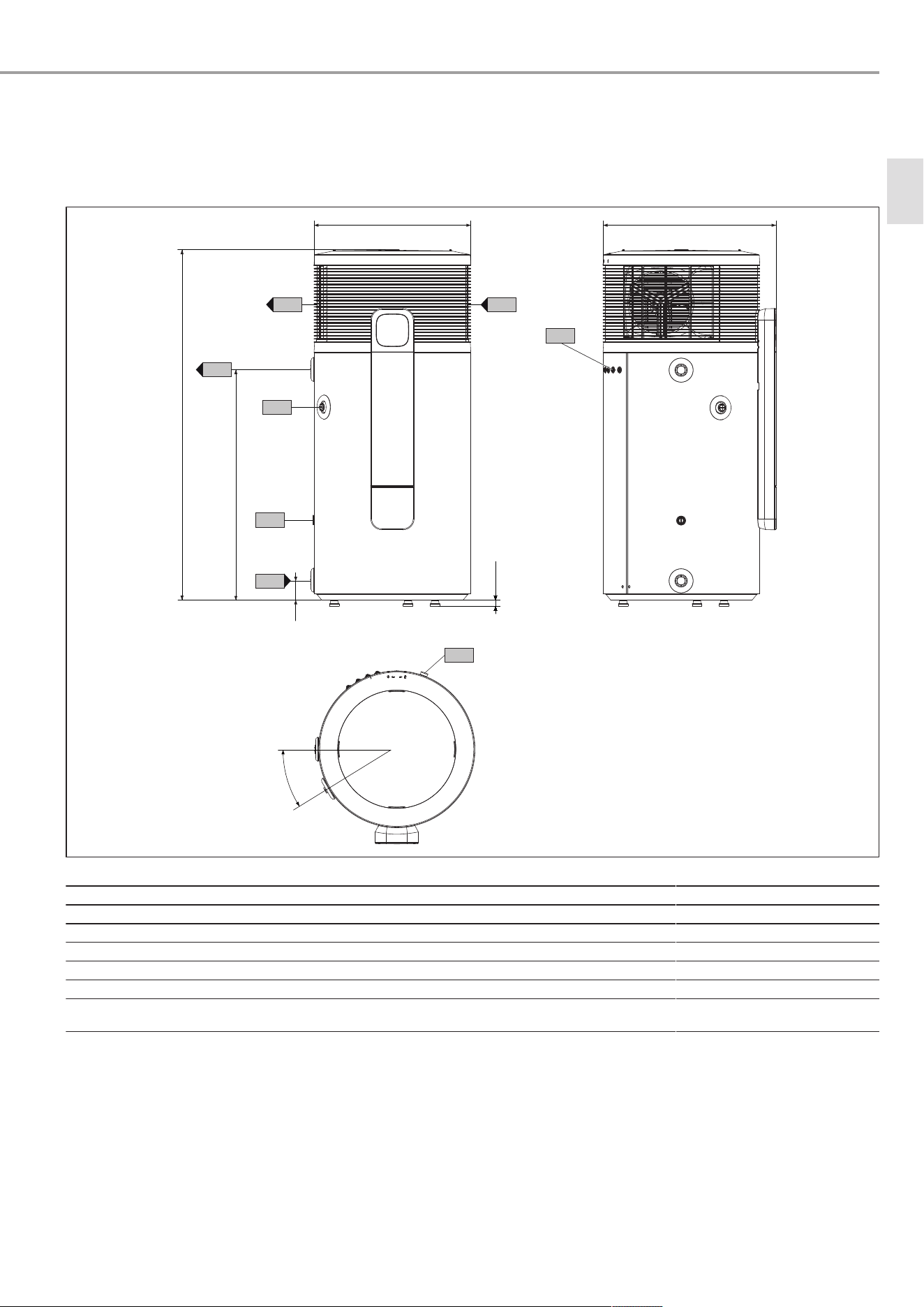
Specification
www.stiebel-eltron.com SHP-O Plus | 25
18 Specification
18.1 Dimensions and connections
18.1.1 SHP-O 200 Plus
650 719
g01
1453
59
957
c01
c06
i43
d45
c13
g02
b01
30°
22-35
D0000117729
b01 Entry electrical cables
c01 Cold water inlet Male thread G 1
c06 DHW outlet Male thread G 1
c13 T&P valve Female thread Rp ½
d45 Condensate drain Male thread G ¾
g01 Air intake
g02 Air discharge
i43 Cover for manufacturing aper-
ture
en
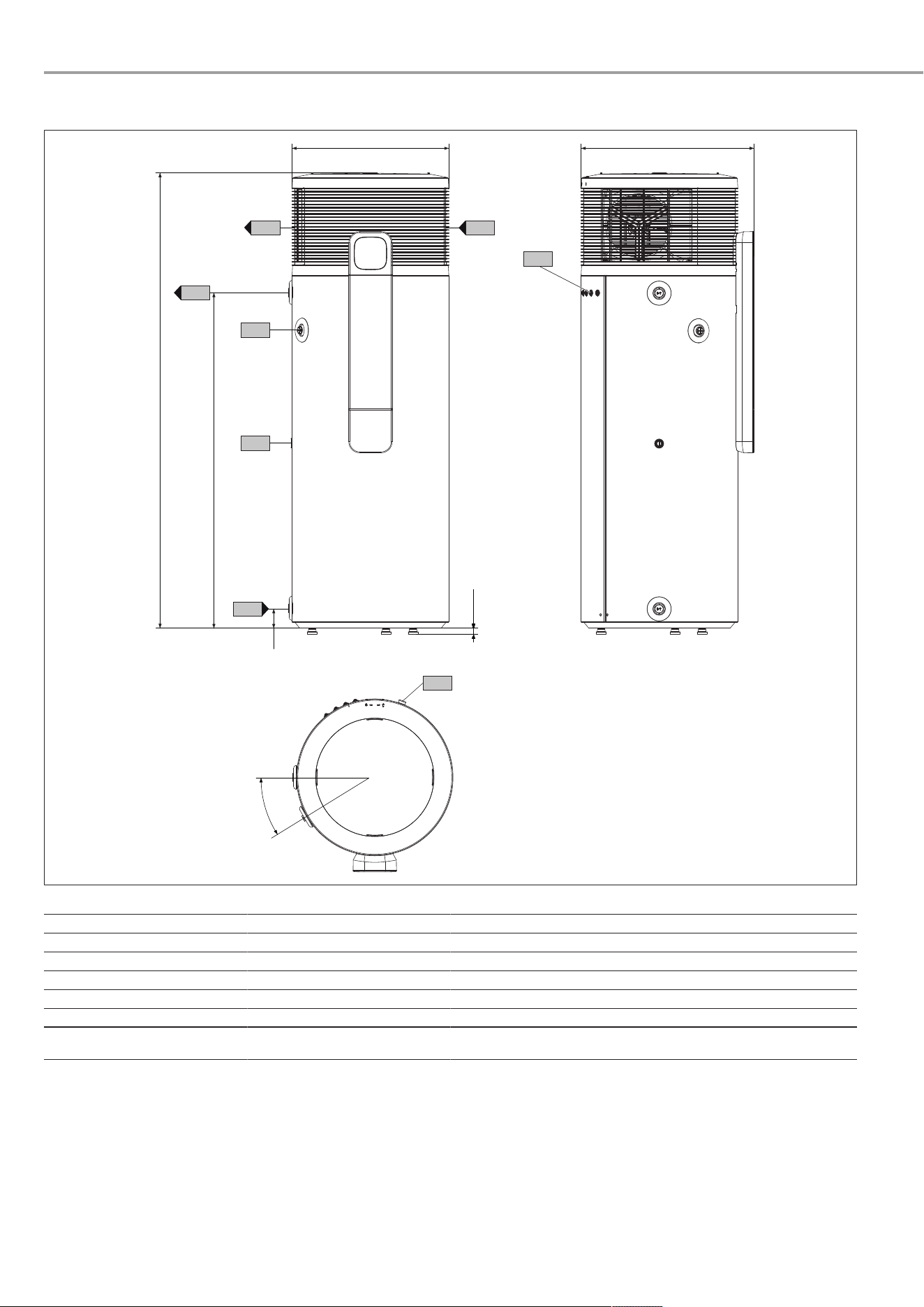
Specification
26 | SHP-O Plus www.stiebel-eltron.com
18.1.2 SHP-O 300 Plus
650
g01
1880
80
1384
c01
c06
i43
c13
g02
b01
30°
d45
719
22-35
D0000117737
b01 Entry electrical cables
c01 Cold water inlet Male thread G 1
c06 DHW outlet Male thread G 1
c13 T&P valve Female thread Rp ½
d45 Condensate drain Male thread G ¾
g01 Air intake
g02 Air discharge
i43 Cover for manufacturing aper-
ture

Specification
www.stiebel-eltron.com SHP-O Plus | 27
18.2 Wiring diagram
AA02 Integral control unit 1 EB R.WWP
AA06 Programming unit
AA09 Wireless module
BP03 Pressure sensor, low pressure (16bar)
BP05 Pressure switch, high pressure (31bar)
BT21/22 Temperature sensor, cylinder top/integral
BT31 Temperature sensor, air intake
BT40 Temperature sensor, hot gas
BT45 Temperature sensor, evaporator discharge
BT55 Temperature limiter, high limit safety cut-out for
emergency and auxiliary heater
BT58 Temperature sensor, fin array, evaporator
CA01 Run capacitor, compressor
EB08 Emergency and auxiliary heater
FA01 Internal motor overload relay
FC11 Fuse 1.25A
FH800 Retainer for fuse
MA01 Compressor motor
MA04 Motor, expansion valve
MA20 Motor, heat pump fan
S200 DIP switch
XD14 SG Ready terminal
XD20 Main connection terminal, internal
XD21 L block terminal
XD22 N block terminal
XD34 Sensor terminal
XD35 Control terminal
XD36 Actuator terminal
XD37 Adaptor terminal
XE17 Earth terminal, cylinder, internal
XE19 Earth stud, terminal plate
XE20 Earth stud, casing
en
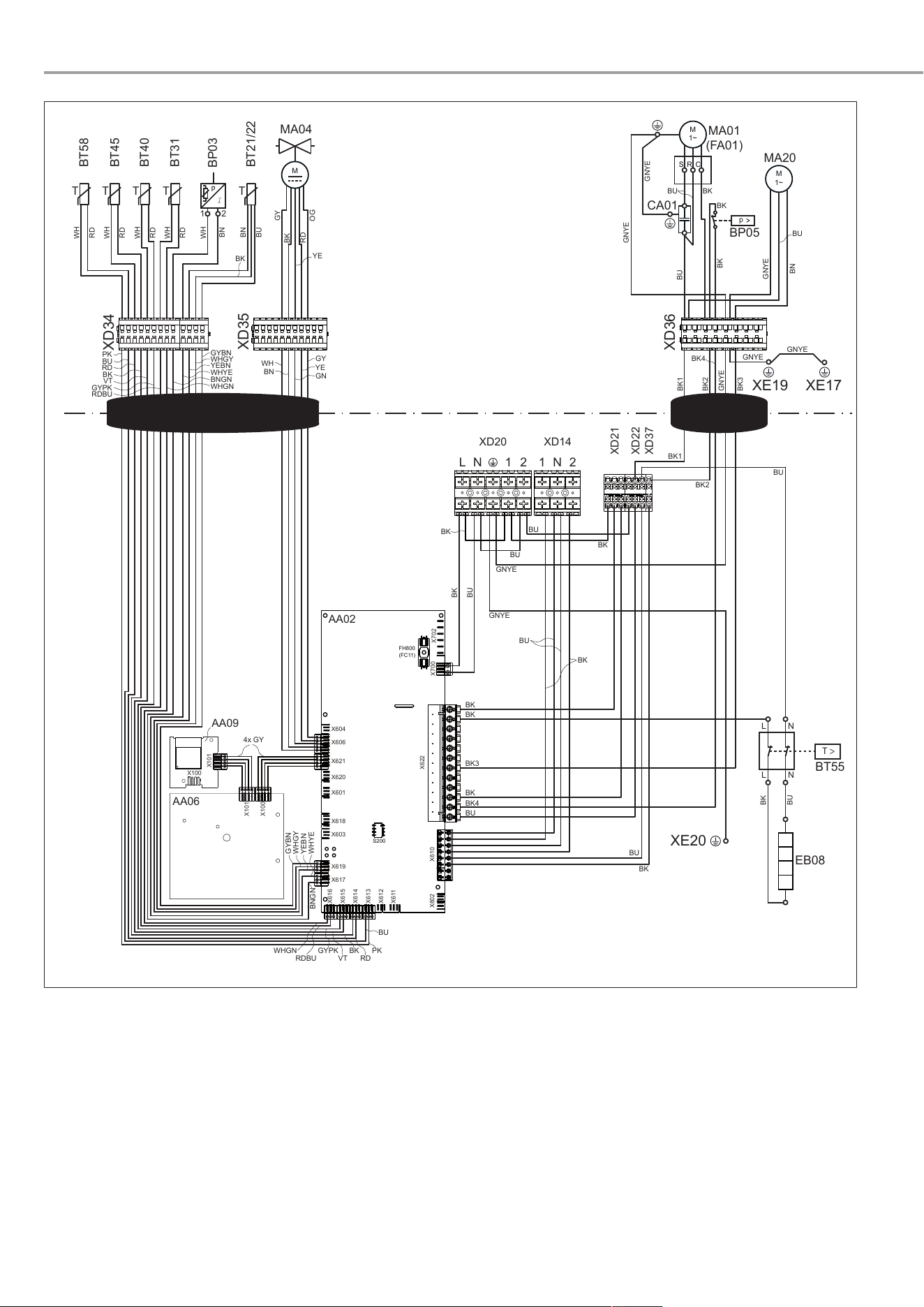
Specification
28 | SHP-O Plus www.stiebel-eltron.com
FH800
(FC11)
S200
AA02
L N 1 2
XD20
M
1~
MA20
C
R
S
M
1~
MA01
(FA01)
XD14
1 N 2
CA01
MA04
M
p
BP05
AA09
AA06
BT55
T >
EB08
T
BT31
T
BT45
T
BT58
T
BT21/22
T
BT40
BP03
1 2
XD21
XD22
WWK-I 200/300 (W) Plus
SHP-I 200/300 (H) Plus
TTA 200/300.1 (SOL) comfort
SHP-O 200/300 Plus
XD34
XD35
XD36
XD37
XE19
XE20
XE17
AA02 Integrierte Regelung 1 EB R.WWP
AA06 Bedieneinheit EB S UNI I2C.P.LED 5V
AA09 Funkmodul EB FFB.A UNI I2C.W 2,4GHz
BP03 Drucksensor Niederdruck (16 bar)
BP05 Druckwächter Hochdruck
(31 bar - selbstrückschaltend)
BT21/22 Temperaturfühler WW Dom/Integral - NTC/PTC
BT31 Temperaturfühler Lufteintritt
BT40 Temperaturfühler Heißgas
BT45 Temperaturfühler Verdampferausgang
BT55 Temperaturwächter STB Not- und Zusatzheizung
BT58 Temperaturfühler Lamellenpaket Verdampfer
CA01 Betriebskondensator Verdichter
EB08 Not- und Zusatzheizung
FA01 Motorschutzschalter intern
FC11 Schmelzsicherung (1,25 A)
FH800 Halterung für Schmelzsicherung
MA01 Motor Verdichter
MA04 Motor Expansionsventil
MA20 Motor WP Lüfter
S200 DIP-Schalter
XD14 Anschlussklemme SG-Ready
XD20 Klemme Hauptanschluss intern
XD21 Klemme L-Block
XD22 Klemme N-Block
XD34 Klemme Sensoren
XD35 Klemme Steuerung
XD36 Klemme Aktorik
XD37 Klemme Adapter
XE17 Erdungsklemme Speicher intern
XE19 Stützstelle Erdung Klemmenblech
XE20 Stützstelle Erdung Gehäuse
X702
X700
X622
X610X602
X604
X606
X621
X620
X601
X618
X603
X619
X617
X616
X615
X614
X613
X612
X611
X101
X100
X101
X100
WH
BN
WH
RD
WH
RD
WH
RD
WH
RD
BN
BU
BK
BK
OG
RD
YE
GY
WH
GN
YE
GY
L N
L N
GNYE
GNYE
GNYE
GNYE
GNYE
GNYE
GNYE
GNYE
BU
BU
BK
PK
BU
RD
BK
VT
RDBU
GYPK
WHGN
BNGN
WHYE
YEBN
WHGY
GYBN
4x GY
YEBN
WHGY
GYBN
BN
WHYE
BNGN
RDBU
WHGN
VT
GYPK
RD
BK PK
BU
BU
BK
BK
BU
BU
BK
BK
BK
BK3
BK
BK4
BU
BU
BK
BU
BK
BU
BK1
BK
BK
BKBU
BN
BU
BK2
BK4
BK2
BK3
BK1
D0000094114

Specification
www.stiebel-eltron.com SHP-O Plus | 29
18.3 Data table
SHP-O 200 Plus SHP-O 300 Plus
204472 204473
Hydraulic data
Nominal capacity l 200 300
Application limits
Max. DHW temperature with
heat pump
°C 65 65
Max. DHW temperature with
emergency/auxiliary heater
°C 65 65
Max. permissible DHW temper-
ature in the cylinder
°C 70 70
High limit safety cut-out °C 89 89
Min./max. application limits,
heat source for heat pump oper-
ation
°C +6/+43 +6/+43
Min./max. application limits,
ambient temperature, cylinder
°C 0/+50 0/+50
Min. installation room volume
(recirculation air mode, general
domestic use)
m³ 13 13
Max. permissible operating
pressure, cold water/DHW
MPa 0.85 0.85
Permissible operating pressure,
refrigerant circuit
MPa 3.1 3.1
Min./max. conductivity, DHW μS/cm 100-1500 100-1500
Power consumption
Power consumption, emer-
gency/auxiliary heater (230V)
kW 1.50 1.50
Average power consumption,
heat pump (230 V) (A19/W15-61
I AS/NZS 5125.1)
kW 0.45 0.44
Max. power consumption, heat
pump (230 V)
kW 0.7 0.7
Electrical data
Power supply 1/N/PE 220-240 V ~ 50 Hz 1/N/PE 220-240 V ~ 50 Hz
Permissible voltage range, ex-
ternal signal transmitter
~ 220-240 V 50/60 Hz ~ 220-240 V 50/60 Hz
Max. operating current A 9.88 9.88
Max. starting current A 19.08 19.08
Fuse protection min.* A C10 C10
Rated voltage V 220-240 220-240
Rated current A 2.25 2.25
Max. power consumption, heat
pump + emergency/auxiliary
heater
kW 2.125 2.125
Sound emissions
Sound power level LWA, indoor
(indoor air)
dB(A) 59 59
Versions
IP rating IP24 IP24
Refrigerant R290 R290
Refrigerant charge kg 0.152 0.152
Global warming potential of the
refrigerant (GWP100)
0.02 0.02
CO2 equivalent (CO2e) t 0.000456 0.000456
Power cable length approx. mm 2000 2000
Default temperature setting °C 61 61
Dimensions
Height mm 1478 1903
Diameter mm 650 650
Height when tilted, incl. pack-
aging
mm 1798 2197
Weights
Weight, empty kg 98 117
en

Specification
30 | SHP-O Plus www.stiebel-eltron.com
SHP-O 200 Plus SHP-O 300 Plus
Weight, full kg 304 422
Connections
Condensate connection G 3/4A G 3/4A
Water connection G 1A G 1A
Safety valve connection Rp 1/2 Rp 1/2
Values
Type of anode Signal anode Signal anode
Air flow rate m³/h 460 460
Recommended number of users 3 4-5
Further details
Maximum height for installation m <2000 <2000
* Fuse protection max. C16

Warranty
www.stiebel-eltron.com SHP-O Plus | 31
19 Warranty
Warranty Stiebel Eltron Australia Only - According to national
regulations in Australia
Stiebel Eltron Warranty for Heat Pumps
Who gives the warranty
1. The warranty is given by Stiebel Eltron (Aust) Pty Ltd
(A.B.N. 82 066 271 083) of 294 Salmon Street, Port Mel-
bourne, Victoria, 3207 (“we”, “us” or “our”).
The warranty
2. This warranty applies to Stiebel Eltron Heat pumps (the
“unit”).
3. Subject to the warranty exclusions we will repair or re-
place, at our absolute discretion, a faulty component in
your unit free of charge if it fails to operate in accordance
with its specifications, and you make a valid warranty
claim in accordance with this warranty, during the war-
ranty period.
4. If we repair or replace a faulty component to your unit un-
der this warranty, the warranty period is not extended
from the time of the repair or replacement.
5. The warranty period commences on the date of comple-
tion of the installation of the unit. Where the date of com-
pletion of installation is not known, then the warranty
period will commence 2 months after the date of manu-
facture.
6. The warranty period for a unit used for domestic purposes
is shown in the table below. Domestic purposes means
that the unit is used in a domestic dwelling.
Component Warranty period
Cylinder and
condenser
5 years
Sealed refriger-
ation system,
including com-
pressor, evap-
orator, valves
and associated
pipe work. All
other electrical
componentry.
2 years
T&P relief valve 1 year
7. The warranty period for a unit used for commercial pur-
poses is shown in the table below. Commercial purposes
means that the unit is used for a non-domestic purpose
and includes but is not limited to being used in a motel,
hotel, mining camp or nursing home.
Component Warranty period
Cylinder and
condenser
2 years
Sealed refriger-
ation system,
including com-
pressor, evap-
orator, valves
and associated
pipe work. All
other electrical
componentry.
2 years
T&P relief valve 1 year
Your entitlement to make a warranty claim
8. You are entitled to make a warranty claim if:
– you own the unit or if you have the owner’s consent to
represent the owner of the unit;
– you contact us within a reasonable time of discover-
ing the problem with the unit and in any event within
30 days.
How you make a warranty claim
9. To make a warranty claim you must provide us with the
following information:
– The model number of the unit;
– A description of the problem with the unit;
– The name, address and contact details (such as phone
number and e-mail address) of the owner;
– The address where the unit is installed and the loca-
tion (e.g. at side of house);
– The serial number of the unit;
– The date of purchase of the unit and the name of the
seller of the unit;
– The date of installation of the unit;
– A copy of the certificate of compliance when the unit
was installed.
10. The contact details for you to make your warranty claim
are:
Name: Stiebel Eltron (Aust) Pty Ltd
Address: 294 Salmon Street, Port Melbourne, Vic-
toria, 3207
Telephone: 1800 153 351
(8.00 am to 5.00 pm AEST Monday to Fri-
day)
Contact person: Customer Service Representative
E-mail: [email protected]
11. We will arrange a suitable time with you to inspect and
test the unit.
Warranty exclusions
12. We may reject your warranty claim if:
– The unit was not installed by a registered and quali-
fied plumber.
– The unit was not installed and commissioned:
– in Australia;
– in accordance with the Operating and Installation
Guide; and
– in accordance with the relevant statutory and
local requirements of the State or Territory in
which the unit is installed.
– The unit has not been operated or maintained in ac-
cordance with the Operating and Installation Guide.
– The unit does not bear its original Serial Number or
Rating Label.
– The unit was damaged by or is faulty due to any or
any combination of the following:
– normal fair wear and tear;
– connection to an incorrect water supply, for ex-
ample, (but not limited to) connection to water
from a bore, dam or swimming pool;
– connection to an incorrect or faulty power supply;
– connection to faulty equipment, such as damaged
valves;
– insufficient air flow;
– foreign matter in the water supply, such as
sludge or sediment;
– corrosive or acidic elements in the water supply,
where the Langelier Saturation Index (LSI) is out-
side the range -1.0 < LSI < 0.8;
– accidental or malicious damage;
– act of God, including damage by flood, storm,
fire, lightning strike, cyclones, earthquakes, nat-
ural disasters or other similar actions of the ele-
ments;
– excessive water pressure, negative water pres-
sure (partial vacuum) or water pressure pulsa-
tion;
– ingress of vermin.
en

Guarantee
32 | SHP-O Plus www.stiebel-eltron.com
– The unit was damaged before it was installed e.g. it
was damaged in transit.
– An unauthorised person has modified, serviced, re-
paired or attempted to repair the unit without our
consent.
– Non genuine parts other than those manufactured or
approved by us have been used on the unit.
13. We may charge you:
– for any additional transport costs if the unit is in-
stalled more than 30 kilometres from our closest au-
thorised service technician.
– for the extra time it takes our authorised service tech-
nician to access the unit for inspection and testing if it
is not sited in accordance with the Operating and In-
stallation Guide or not readily accessible for inspec-
tion.
– for any extra costs of our authorised service techni-
cian to make the unit safe for inspection.
14. You must ensure that access to the unit by our authorised
service technician is safe and free from obstruction.
15. Our authorised service technician may refuse to inspect
and test the unit until you provide safe and free access to
it, at your own cost.
16. If we reject your warranty claim in accordance with clause
12, we may charge you for our authorised service techni-
cian’s labour costs to inspect and test the unit.
17. In order to properly test the unit we may remove it to an-
other location for testing.
Australian Consumer Law
18. Our goods come with guarantees that cannot be excluded
under the Australian Consumer Law. You are entitled to a
replacement or refund for a major failure and compensa-
tion for any other reasonably foreseeable loss or damage.
You are also entitled to have the goods repaired or re-
placed if the goods fail to be of acceptable quality and the
failure does not amount to a major failure.
19. The Stiebel Eltron warranty for the unit is in addition to
any rights and remedies you may have under the Aus-
tralian Consumer Law.
20 Guarantee
The guarantee conditions of our German companies do not ap-
ply to appliances acquired outside of Germany. In countries
where our subsidiaries sell our products a guarantee can only
be issued by those subsidiaries. Such guarantee is only granted
if the subsidiary has issued its own terms of guarantee. No other
guarantee will be granted.
We shall not provide any guarantee for appliances acquired in
countries where we have no subsidiary to sell our products. This
will not affect warranties issued by any importers.
21 Environment and recycling
u Dispose of the appliances and materials after use in accord-
ance with national regulations.
u If a crossed-out waste bin is pictured on the ap-
pliance, take the appliance to your local waste
and recycling centre or nearest retail take-back
point for reuse and recycling.
This document is made of recyclable paper.
u Dispose of the document at the end of the appli-
ance's life cycle in accordance with national reg-
ulations.

www.stiebel-eltron.com SHP-O Plus | 33

34 | SHP-O Plus www.stiebel-eltron.com

www.stiebel-eltron.com SHP-O Plus | 35

Comfort through Technology
FR
4 0 1 7 2 1 3 6 5 7 7 4 3
A 365774-46923-0027
B 366674-46923-9974
STIEBEL ELTRON GmbH & Co. KG
Dr.-Stiebel-Straße 33 | 37603 Holzminden | Germany
[email protected] | www.stiebel-eltron.com