DC Charger
Installation and Operation Manual
Version: 1.0

Introduction
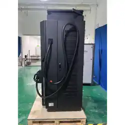
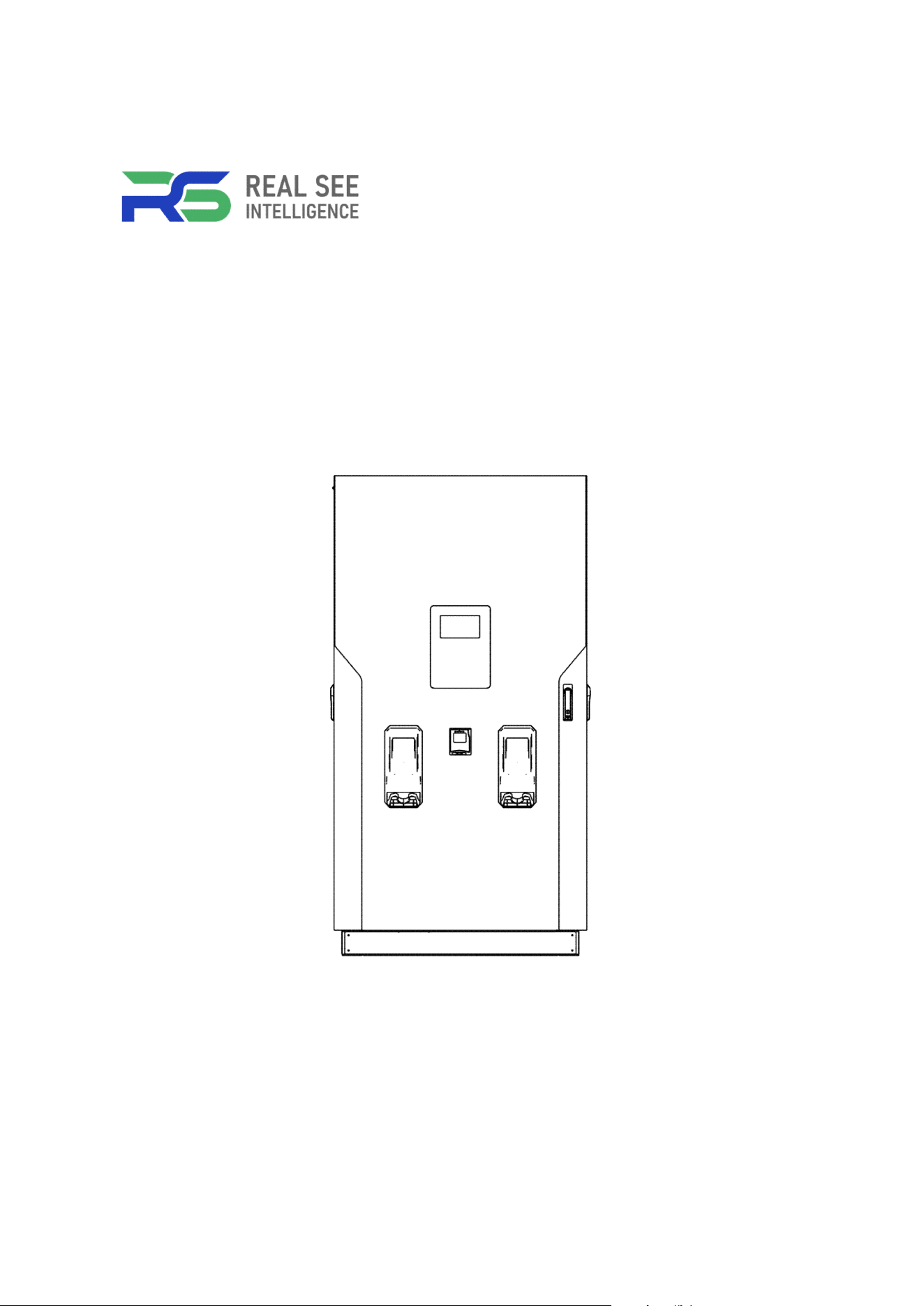
The dual-gun DC charger delivers fast and efficient charging for two EVs simultaneously. Its intelligent
power distribution, robust safety protection, and Type 3R-rated design make it ideal for commercial and
fleet applications requiring reliable and high-performance charging solutions.
Features
● Wide-Range Fast DC Charging
● Smart Interface and Connectivity Options
● Integrated Payment and User-Friendly Operation
● Durable Modular Architecture for Heavy-Duty Environments
● User-Friendly Cable Management and Comprehensive Protection
● Stable Thermal Architecture for Continuous High-Load Operation
Applications
● Public Parking Lots
● Office EV Parking Areas
● Highway Service Areas
● Fleet Operation Centers
● Large Commercial Charging Stations
● Commercial Fleet Depots
● Logistics and Distribution Hubs
● Industrial Charging Centers
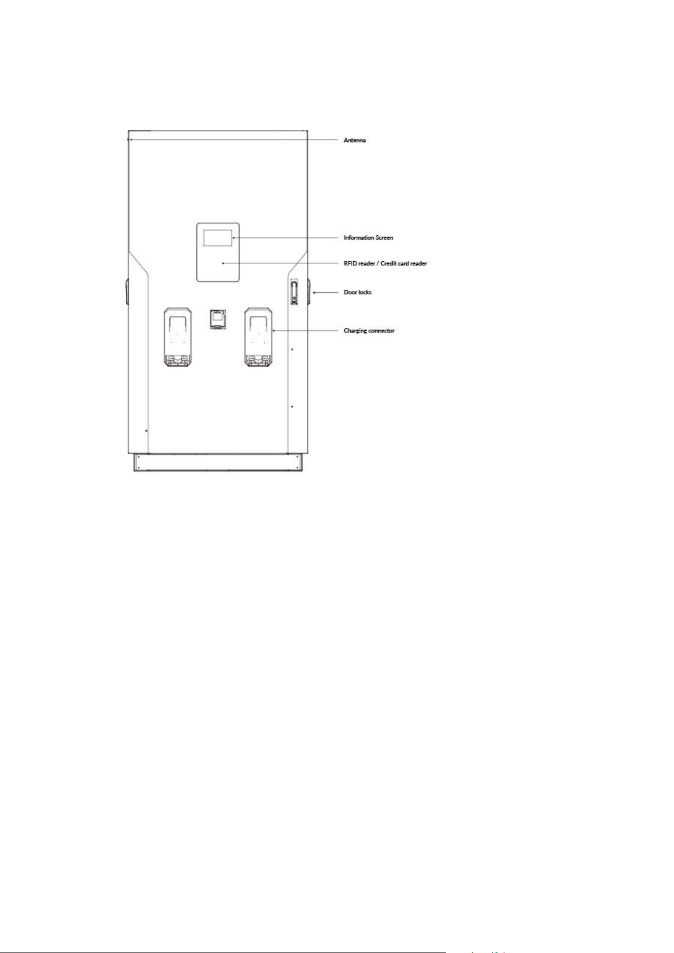
Basic User Interface
Accessory Kit
RFID cards x 2 Keys x 2 User manual x 1 Aluminum base cover x 1 Mounting template x 1
Side wiring cover x 1 Expansion bolts x 4 M12 bolts x 4

Important Safety and Wiring Instructions
1. Safety and Compliance
IMPORTANT SAFETY INSTRUCTIONS
SAVE THESE INSTRUCTIONS
This manual contains important instructions that shall be followed during installation, operation and maintenance of
the unit.
This document provides instructions for EV Charger and should not be used for any other product.
The product can only be installed by a licensed contractor, and/or a licensed electrician in accordance with all
applicable state, local and national electrical codes and standards in a location with non restricted access.
Service should be carried out in compliance with safety and hygiene requirements work and ergonomics, taking into account
the instructions contained in this documentation.
● Before installing the product, review this manual carefully and consult with a licensed contractor, licensed
electrician and trained installation expert to ensure compliance with local building practices, climate conditions,
safety standards, and state and local codes.
● DC City Charger meets the requirements specified in the regulations by using dedicated devices and systems.
● Do not install or use DC City Charger if the enclosure is broken, cracked, open or shows any other indications
of damage.
● Make sure that the materials used and the installation procedures follow local building codes and safety standards.
● Do not put tools, material or body parts into the electric vehicle connector.
● The information provided in this manual in no way exempts the user of responsibility to follow all applicable
codes or safety standards.
● The manufacturer is not responsible for physical injury, damage to property or damage to equipment caused during
the installation of this device.
● Emergency stop button is available to stop the EVSE when under emergency situation.
● Keeping DC City Charger in technical condition and ensuring cleanliness use without compromising safety.
● Maximum ambient temperature: DC City Charger operates from -20 ºC to +50 ºC.
● This device complies with Part 15 of the FCC Rules. Operation is subject to the following two conditions: (1)
this device may not cause harmful interference, and (2) this device must accept any interference received,
including interference that may cause undesired operation.
GROUNDING INSTRUCTIONS - This unit is must be connected to a grounded, metal, permanent wiring system; or an
equipment-grounding conductor with circuit conductors and connected to equipment-grounding terminal or lead on battery
charger. Connections to battery charger must comply with all local codes and ordinances.

CA U T IO N
Risk of electric shock. Do not remove cover or attempt to open the enclosure. No user serviceable parts inside. Refer
servicing to qualified service personnel.
Risk of electric shock. Refer to bottom of unit for cautionary markings.
Identify parts not earth grounded are not grounded - they presents risk of electric shock. Test before touching.
Have defective cords or wires replaced immediately by a qualified service person.
CAUTION - Risk of electric shock. Capacitor stores hazardous energy. Do not remove cover until 5 minutes after
disconnecting all sources of supply.
WARN I N G
This devices is intended only for charging vehicles not requiring ventilation during charging.
To reduce the risk of fire, replace only with same type and ratings of fuse.
DO NOT INSTALL ON OR OVER COMBUSTIBLE SURFACES.
AT T E N T IO N
Risque de choc électrique. Ne pas retirer le couvercle ni essayer d’ouvrir le boîtier.
Risque de choc électrique. Consulter au bas de l'unité pour voir les marques de mise en garde.
Aucune pièce interne réparable par l’utilisateur. Confier tout travail d’entretien ou de réparation à un technicien
qualifié.
Pour réduire le risque d’incendie, remplacez seulement par le même type et les cotes de fusible.
Attention - risque de choc eléctrique. Le condensateur stocke I’énergie dangereuse. Ne retirez le couvercle que 5
minutes après avoir débranché toutes les sources d’alimentation
AVER IT S S E M E NT
Ce dispositif est destiné au chargement des véhicules ne nécessitant pas de ventilation au cours du chargement.
Identifier les pièces qui ne sont pas mises à la terre ne sont pas mises à la terre - elles présentent un risque de
choc élecctrique. Testez avant de toucher.
Faites remplacer immédiatement les cordons ou les fils défectueux par une personne de service qualifiée.
NE PAS INSTALLER SUR OU AU-DESSUS DE SURFACES COMBUSTIBLES.
2. Electrical Service Wiring
WARNING!
Danger of electrical shock or injury. Turn off power at the panel board or load center before working inside
the equipment or removing any component. Do not remove circuit protective devices or any other component until the
power is turned off.
Grounding Instructions
DC City Charger must be permanently grounded. Always connect the Protective Earth (PE) first, before
connecting the phase and neutral wiring to avoid hazardous voltage.
1) An insulated grounding conductor that is identical in size, insulation material, and thickness to the grounded and
ungrounded branch-circuit supply conductors except that it is green with or without one or more yellow stripes is to
be installed as part of the branch circuit that supplies the unit or system.
2) The grounding conductor described in item 1 is to be grounded to earth at the service equipment or, when supplied
by a separately derived system, at the supply transformer.
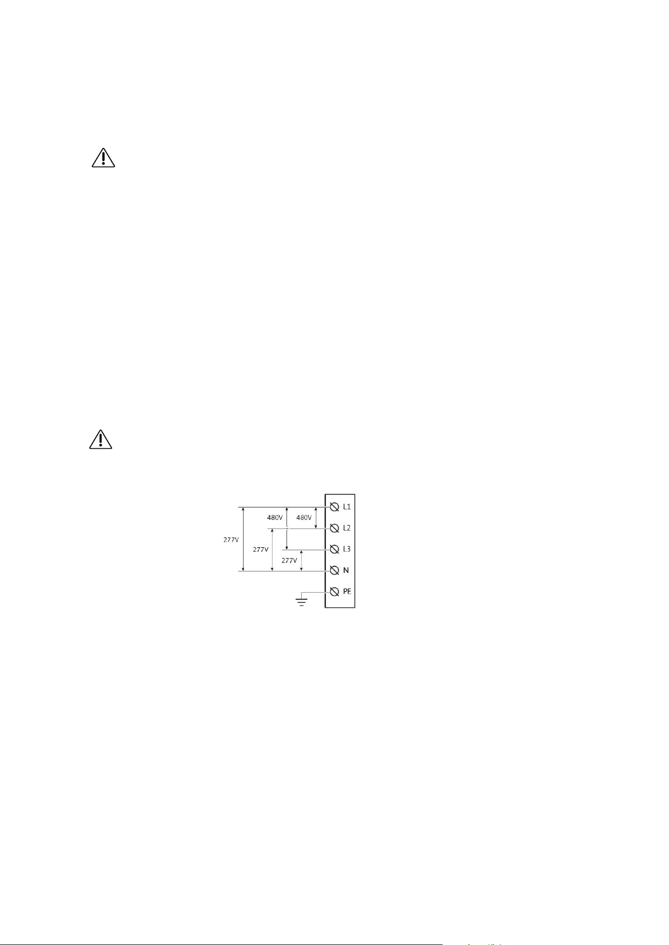
480V Three-Phase
WARNING!
The following diagram illustrates DC City Charger connection to L1, L2, L3, and neutral in a Wye power grid feed.

Before Installation
● Read all the instructions before using and installing this product.
● Do not use this product if power cable or charging cable have any damage.
● Do not use this product if the enclosure or charging connector are broken or on or if there is damage.
● Do not put any tool, material, finger or other body part into the charging connector or EV connector.
● Do not twist, swing, bend, drop or crush the charging cable. Never drive over it with a vehicle.
WARNING:The product should be installed only by a licensed contractor and/or licensed technician in
accordance with all building codes, electrical codes and safety standards.
WARNING: The product should be inspected by a qualified installer prior to initial use. Under no circumstances
will compliance with the information in this manual relieve user of his /her responsibilities to comply with all
applicable codes and safety standards.
● Power feed must be 3 Phase Wye configuration with TN(-S)/ TT grounding systems.
● In the installation of TN(-S) system: the neutral (N) and the PE of the power distribution are directly connected
to the earth. The PE of the charger equipment is directly connected to the PE of power distribution and separate
conductor for PE and neutral (N).
● In the installation of TT system: the neutral (N) and the PE of the power distribution are directly connected
to the earth. The PE of the charger equipment is isolated to the PE of power distribution to the earth.
● The capacity of power supply should be higher than 196 kVA in order to function correctly.
● The product should be installed in free air area and keep at least 30cm (12 inches) clearance distance to all
air vent of the product.
● Recommend to keep not less than 100cm (3 ft. 6 in.) clearance distance from all around the product following
NEC table 110.26 condition 2, 151-600V.
NOTICE
It is recommended to conduct Wi-Fi and 3G/4G signal strength while charger installation. The RSSI (Received Signal
Strength Indication) value is considered as good as higher than -65dBm. Poor connection quality might interrupt charging
process or data transaction.
Installing the DC Charger
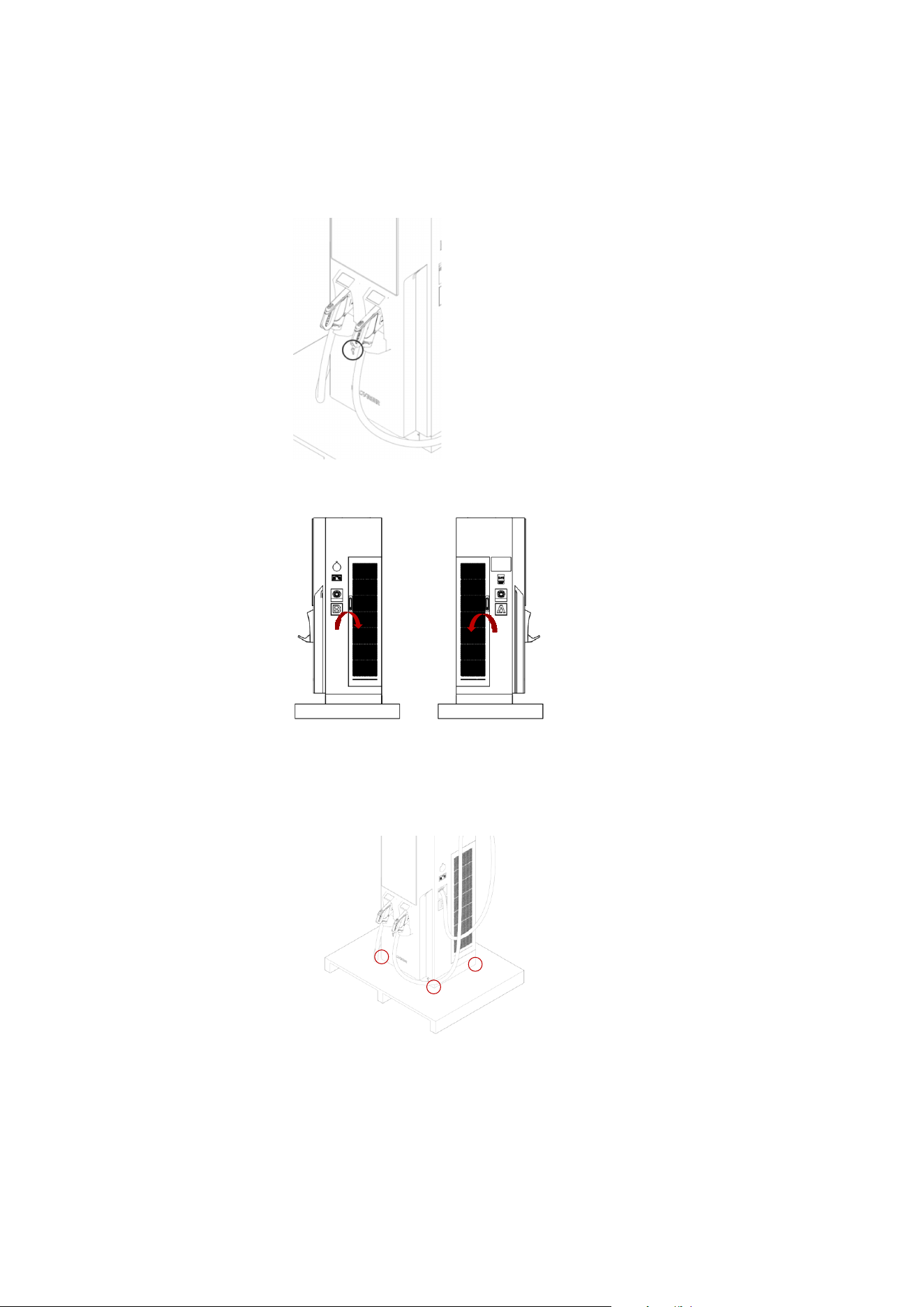
Preparation
1. Take the key from the handle of the charging connector.
2. Open the left door (clockwise) and right door (anticlockwise).
Press the handle back to the lock slot to make sure that the door lock is closed.
3. Release the 4 screws on the base panel (two sides) with a Torx® Tamper-Resistant T15 & T20 screwdriver. Take out
the base panel.
4. Release the screws on the cabinet and pallet with a No. 19 socket wrench.
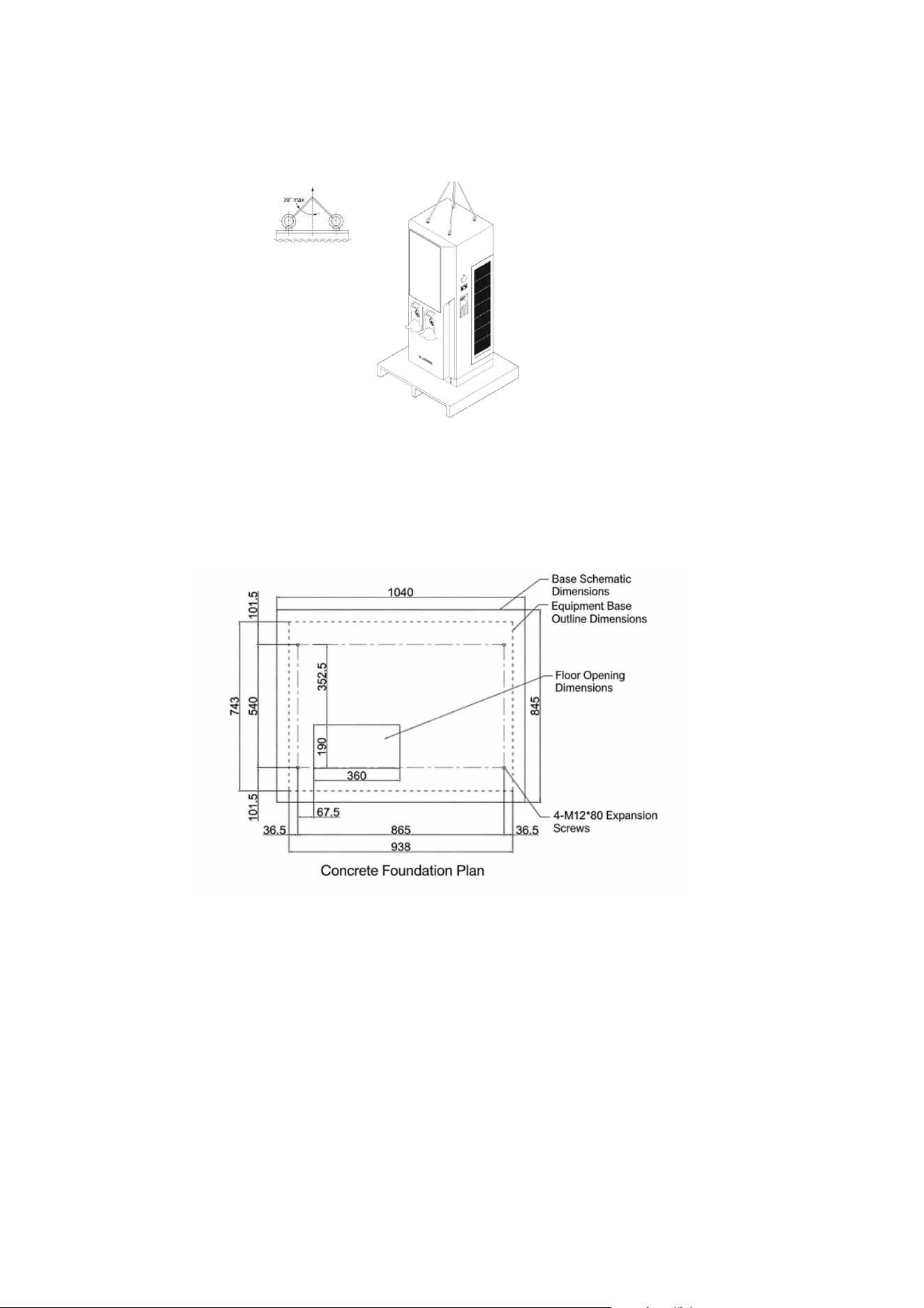
5. Transport the cabinet.
Transporting with the crane: The included angle hanging the cabinet on the top shall be 30°.
6. Replace the eye bolts with M12 bolts x4 with a No. 19 socket wrench after the DC charger has been well-placed.
Ground mounting
The EV Charger shall be installed on the ground. During installation, it must be securely and reliably fixed. It is
recommended that the foundation be constructed in accordance with the following foundation drawing:
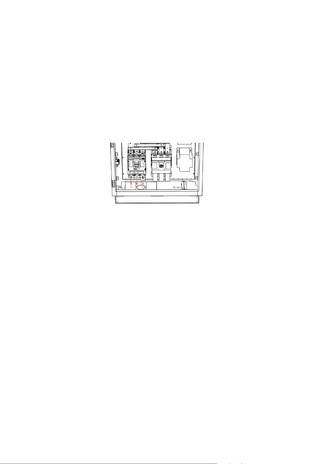
Making the Connection
Power Wiring
● The electrical installation of the DC charger must be carried out under the guidance of professional technical
personnel. Open the front door of the charging pile and connect the incoming power cable to the upper terminals
of the circuit breaker. Connect the grounding wire to the grounding bolt.
● The charger input uses a three- phase four- wire AC power supply, and the AC incoming current is approximately
235A.
● It is recommended to select copper core cables that meet US standards. Use wire terminals matching the cable
cross- section for crimping. The exposed parts of the terminal connections must be insulated with heat- shrinkable
sleeves or insulating tape. The wiring is shown in the following diagram:
● The AC incoming cable enters the charger from the bottom and is connected to the AC input terminals and the ground
terminal inside the charger. The AC input must be wired in accordance with the incoming line markings. The upstream
circuit breaker and distribution cabinet for the charger must be selected and operated by professional electrical
personnel.
Power- On Preparation
1. Personnel Requirements
Users must complete operation training before using the charger. During operation, they must wear appropriate work
clothes and insulated shoes. Individuals with long hair must wear safety helmets.
2. Pre- Use Inspection
In accordance with electrical operation standards, check the interior of the cabinet for any electrical damage or
displacement. Ensure all terminals are securely crimped and free of damage or burning.
Open the front cabinet door, set the circuit breaker to the ON position, and close the control circuit air switch to
perform a continuity test and ensure there is no short circuit.
Set the circuit breaker to the OFF position to disconnect it. Turn off the control circuit air switch and connect the
AC input power cable.
After applying AC input power, first confirm that the emergency stop button is in the released position. Then turn
on the circuit breaker and air switch, and use a multimeter to verify that power has been applied.
Before charging, inspect the charging gun, the insulators of the charging socket, the pins, and the jacks for any foreign
objects. If any foreign objects are found, please clean them.
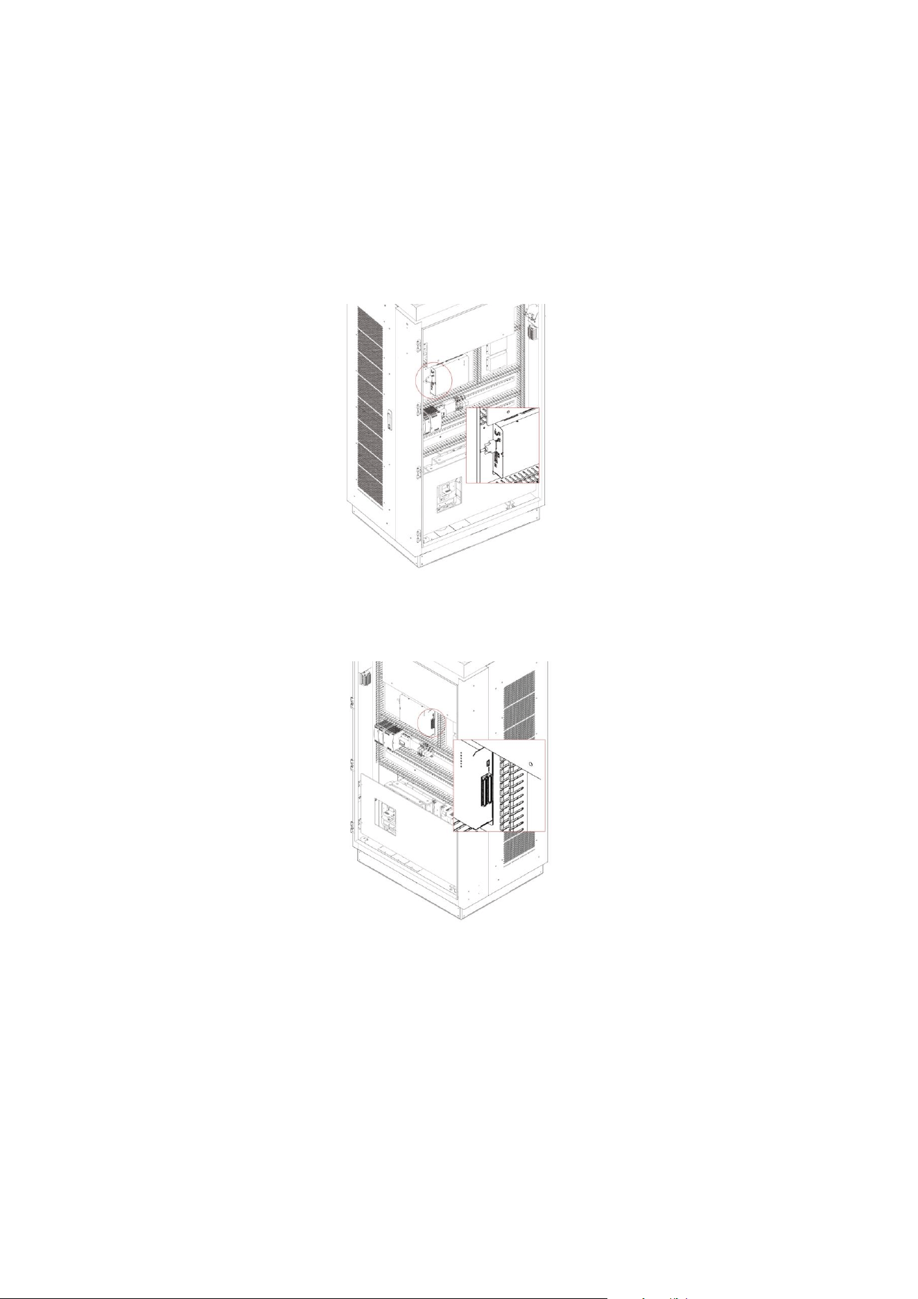
Ethernet Connection
1. It is recommended to connect Ethernet cables through the underside access ports. It is necessary to open the front
cover and the left door.
2. Make sure that the cable passes through the grommet and reaches the Ethernet terminal on the upper controller, as
shown in the following figure.
3. Connect the Ethernet cable to the Ethernet terminal.
4. Fasten the cable on the brackets with cable ties.
Cellular Connection
1. Open the door.
2. Insert mirco SIM card onto the micro SIM interface on the upper controller.
Note:
Insert a valid SIM card as detailed above to start cellular connection. Consult with local operator to activate data
service on the SIM card beforehand. Disable PIN check on the SIM card before inserting the card into the modem. Request
APN information from the operator and make sure APN is configured correctly via the configuration tool.
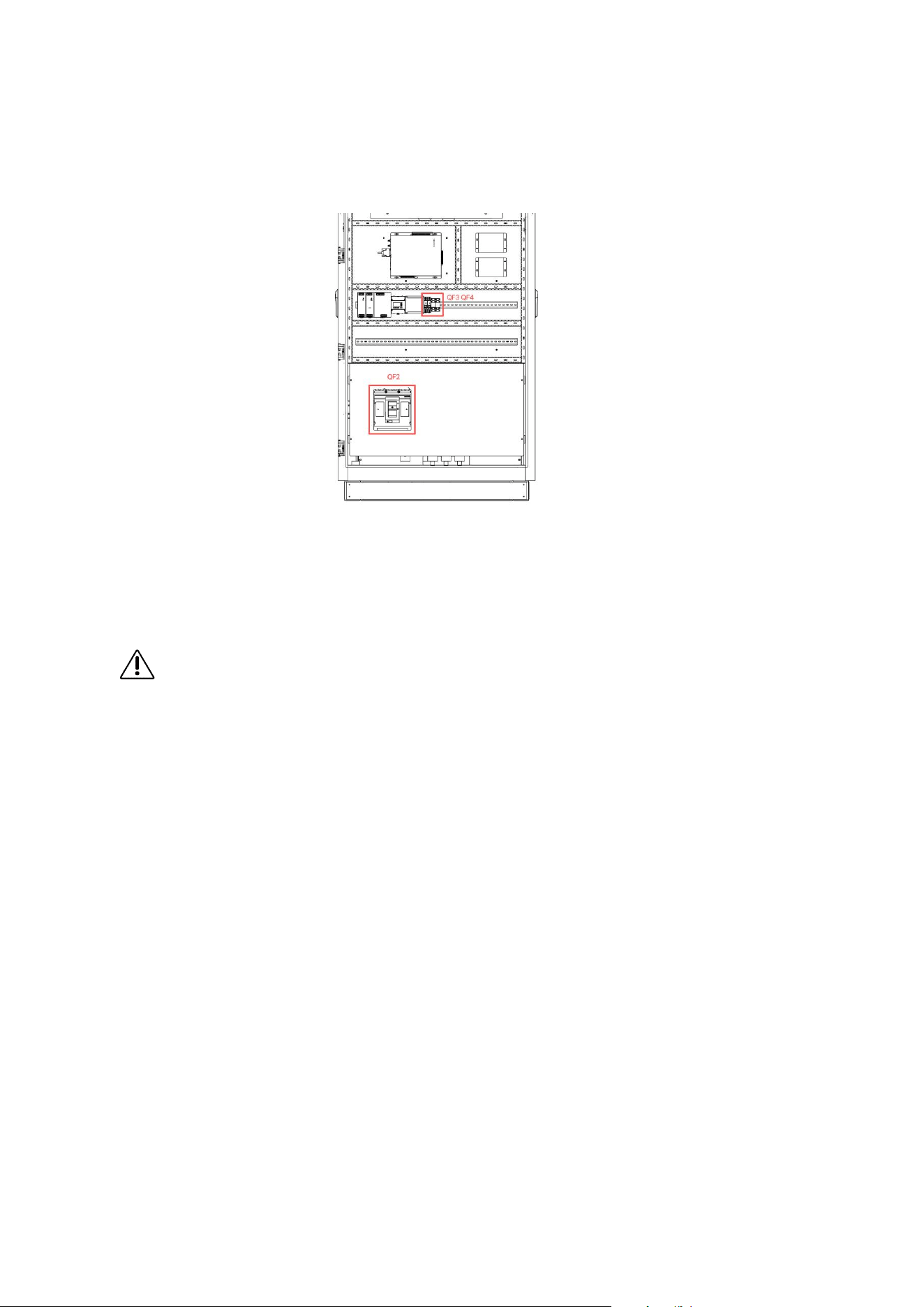
Switch on DC Charger
1. Open the door of City Charger, AC input breaker QF2, QF3, QF4 are marked on the side panel. Follow the steps
to turn on City Charger: QF3 — QF4 — QF2.
2. Switch the power on to initialize DC Charger.
3. DC Charger is ready to charge.
4. To switch off City Charger, open the left door of City Charger, AC input breaker QF2, QF3, QF4 are marked on
the side panel. Follow the steps to turn on City Charger: QF2 — QF4 — QF3.
WARNING!
Under emergency situation, press Emergency button to stop power output.
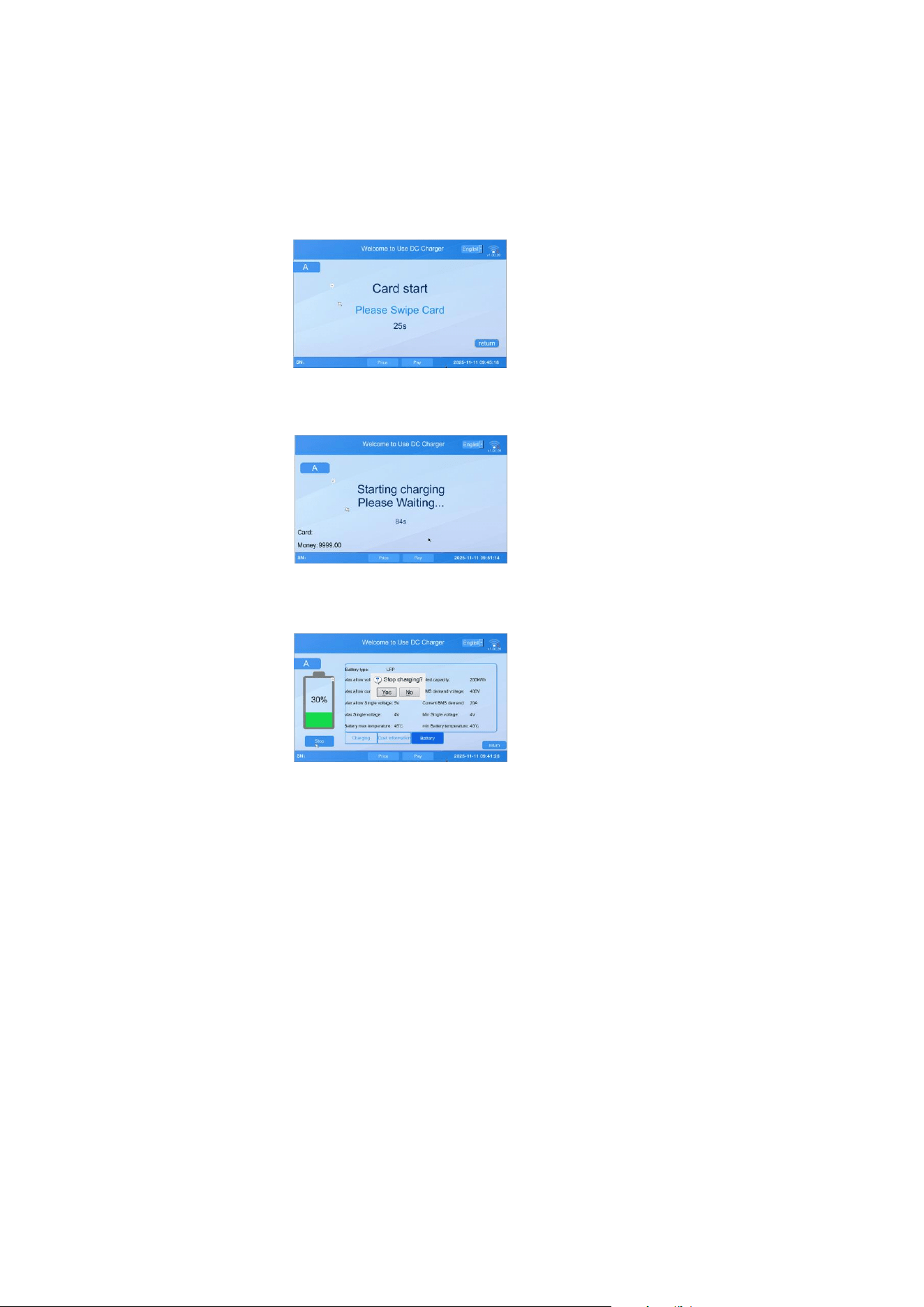
Operation
1. Choose a compatible charging connector.
2. Connect the charging connector to the EV.
3. Swipe the authorized RFID card to start charging.
4. Once charging session starts, status information is displayed on the screen.
5. To stop charging session, press Stop on the screen and swipe the authorized RFID card.
6. Return the charging connector to the holder.
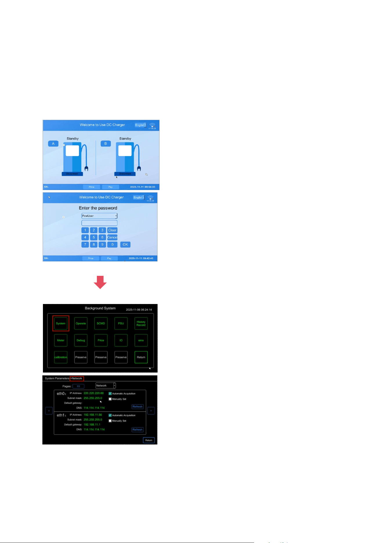
System Configuration
To enter the system interface for debugging
Tap the top- left and top- right corners of the screen repeatedly in the sequence left → right → left → right, as
indicated by the red boxes in the diagram below. Continue until the login dialog appears.
Select Admin Mode. The default password is the current day of the month followed by 1234. For example, if today is
the 25th, the password would be 251234.

System Code
Error Code Fault Cause Error Code Fault Cause
0
No Error
30
Charging Module Over-Temperature Fault
1
E-Stop Button Pressed
31
Charging Module Communication Alarm
3
AC Circuit Breaker Fault
32
Charging Module Fan Alarm
4
DC Bus Output Contactor Fault
33
Access Control Fault
5
DC Bus Output Fuse Fault
34
DC Output Contactor Adhesion Fault
6
Charging Port Electronic Lock Fault
35
Insulation Monitoring Alarm
7
Charger Fan Fault
36
Discharge Circuit Fault
8
Surge Protector Fault
37
Charging Pile Over-Temperature Alarm
9
Insulation Detection Fault
38
Charging Gun Over-Temperature Alarm
11
Vehicle Control Pilot Fault During
Charging
39
AC Input Contactor Refusal/Maloperation
Fault
12
Charging Pile Over-Temperature Fault
40
AC Contactor Adhesion Fault
13
Charging Port Over-Temperature Fault
41
Auxiliary Power Supply Fault
14
Charging Gun Not Returned Alarm
42
Parallel Contactor Refusal/Maloperation Fault
15
BMS Communication Fault
43
Parallel Contactor Adhesion Fault
16
AC Input Over-Voltage Fault
44
Charging Module Communication Fault
17
AC Input Under-Voltage Fault
103
Energy Meter Communication Lost
18
DC Bus Output Over-Voltage Fault
104
IC Card Reader Communication Lost
19
DC Bus Output Under-Voltage Fault
105
Communication Fault with Upper Computer
20
DC Bus Output Over-Current Fault
225
BMS Abnormal Charging Termination
21
Charging Module Fault
226
Charging Pile Detects Other BMS Abnormal
Termination
22
Charging Module AC Input Fault
1009
Network Disconnection Shutdown
23
Charging Module Input Over-Voltage
Fault
1110
Card Swipe Shutdown
24
Charging Module Input Under-Voltage
Fault
1018
Account/Password Shutdown
25
Charging Module Input Phase Loss Fault
1019
Reached Charge Limit Shutdown
26
Charging Module Output Short-Circuit
Fault
1020
Reached Amount Limit Shutdown
27
Charging Module Output Over-Current
Fault
1021
Reached Time Limit Shutdown
28
Charging Module Output Over-Voltage
Fault
1022
Insufficient Account Balance
29
Charging Module Output Under-Voltage
Fault
1023
Stopped at Server-Preset SOC

Maintenance
Annual Requirements
1. Replace the ventilation filter.
2. Conduct a visual inspection of the charging cable and ensure that the cable does not show any
visual damage or deformation.
3. Conduct a visual inspection of the charging connector and ensure that the connector does
not show any visual damage, arcing or rust.
WARNING!
To avoid danger of electrical shock or injury, turn off power at the panel board or load center
before working on the equipment or removing any component. Do not remove circuit
protective devices or any other component until the power is turned off.
Disconnect electrical power to DC City Charger before any maintenance work to ensure that
it is separated from the supply of AC mains. Failure to do so may cause physical injury or
damage to the electrical system and charging unit.
Note:
Even when the key switch is turned off, the circuit before the main terminal is still
hazardous. Please only operate visual inspection at this moment.
Maintenance of the DC City Charger shall be conducted only by a qualified technician.
After opening the front door, turn off the main breaker and auxiliary breaker before any
maintenance work.
Specifications
Model Number CNAC-60kW/2 Series CNAC-120kW/2 Series CNAC-180kW/2 Series
Product Type DC Fast Charging Station
Output Voltage 200-1000V DC
Input Voltage 480V AC, 50/60 Hz
Max Input 78A 156A 233A
Output Current 5-200A 5-400A 5-500A
Maximum Power Output 60kW 120kW 180kW
Input Wire TN-S, L1+L2+L3+N+PE
Charging Connector Type CCS1
Cable Length Cable Management, 2×18FT/5.5m Standard (2×25FT/7.5m Optional)
Charging Modes Mode 4
Charging Protocols OCPP 1.6, ISO 15118
Dimensions (H × W × D) 2103mm*1036.4mm*1244.2mm
Weight 200kg 280kg 360kg
Operating Temperature -20°C to 50°C(-4°F to 122°F)
Operating Humidity <95% Non-condensing
Altitude Up to 2000m
Enclosure Rating NEMA Type 3R
Protection Function
Under current Protection, Over current Protection, Under voltage Protection,
Over voltage Protection, Short Circuit Protection, Residual Current Device,
Over Temperature Protection, Surge Protection, Ground Fault Protection,
Control Pilot Fault Protection, Leakage Protection
Emergency Stop E-stop Button
Communication Interface
7-inch Touchable Screen(10inch Optional), Ethernet, Bluetooth/Wi-Fi,
OCPP 1.6J platform, 4G(Optional)35-inch LCD Advertising Screen, Wi-Fi, LAN Ethernet,
4G
Control Method
RFID card(offline and online), Nayax POS, Plug n Play, VIN code,
QR code, Credit Card
Mounting Type Floor Standing Installation
Compliance Standards CSA, FCC, Energy Star, NTEP compliance, ISO15118 compliance
Standards NEC625, UL817, UL991, UL2231, UL2251, UL2202, OCPP1.6J Compliance
Warranty Period 3 years
Indicator Light Standby: Green on; Charging: Green flashes; Fault: Red on
Lighting Atmospheric Neon LED Light
Heat Dissipation Method Air Cooling
Recommended Air-break 100A 200A 300A
Recommended Input Cable Type
2 AWG, 90℃, copper 4/0 AWG, 90℃, copper 400Kcmil, 90℃, copper

Model Number CNAC-240kW/2 Series CNAC-300kW/2 Series CNAC-360kW/2 Series
Product Type DC Fast Charging Station
Output Voltage 200-1000V DC
Input Voltage 480V AC, 50/60 Hz
Max Input 311A 385A 466A
Output Current 5-700A 5-700A 5-700A
Maximum Power Output 240kW 300kW 360kW
Input Wire TN-S, L1+L2+L3+N+PE
Charging Connector Type CCS1
Cable Length Cable Management, 2×18FT/5.5m Standard (2×25FT/7.5m Optional)
Charging Modes Mode 4
Charging Protocols OCPP 1.6, ISO 15118
Dimensions (H × W × D) 2103mm*1036.4mm*1244.2mm
Weight 440kg 520kg 600kg
Operating Temperature -20°C to 50°C(-4°F to 122°F)
Operating Humidity <95% Non-condensing
Altitude Up to 2000m
Enclosure Rating NEMA Type 3R
Protection Function
Under current Protection, Over current Protection, Under voltage Protection,
Over voltage Protection, Short Circuit Protection, Residual Current Device,
Over Temperature Protection, Surge Protection, Ground Fault Protection,
Control Pilot Fault Protection, Leakage Protection
Emergency Stop E-stop Button
Communication Interface
7-inch Touchable Screen(10inch Optional), Ethernet, Bluetooth/Wi-Fi,
OCPP 1.6J platform, 4G(Optional)35-inch LCD Advertising Screen, Wi-Fi, LAN Ethernet,
4G
Control Method
RFID card(offline and online), Nayax POS, Plug n Play, VIN code,
QR code, Credit Card
Mounting Type Floor Standing Installation
Compliance Standards CSA, FCC, Energy Star, NTEP compliance, ISO15118 compliance
Standards NEC625, UL817, UL991, UL2231, UL2251, UL2202, OCPP1.6J Compliance
Warranty Period 3 years
Indicator Light Standby: Green on; Charging: Green flashes; Fault: Red on
Lighting Atmospheric Neon LED Light
Heat Dissipation Method Air Cooling
Recommended Air-break 400A 500A 600A
Recommended Input Cable Type
2*250Kcmil, 90℃, copper 2*300Kcmil, 90℃, copper 2*400Kcmil, 90℃, copper

FCC Caution.
This device complies with part 15 of the FCC Rules. Operation is subject to the following two
conditions:
(1) This device may not cause harmful interference, and
(2) this device must accept any interference received, including interference that may cause
undesired operation.
Any Changes or modifications not expressly approved by the party responsible for compliance
could void the user's authority to operate the equipment.
Note: This equipment has been tested and found to comply with the limits for a Class B digital
device, pursuant to part 15 of the FCC Rules. These limits are designed to provide reasonable
protection against harmful interference in a residential installation. This equipment generates
uses and can radiate radio frequency energy and, if not installed and used in accordance with the
instructions, may cause harmful interference to radio communications. However, there is no
guarantee that interference will not occur in a particular installation. If this equipment does
cause harmful interference to radio or television reception, which can be determined by turning
the equipment off and on, the user is encouraged to try to correct the interference by one or
more of the following measures:
-Reorient or relocate the receiving antenna.
-Increase the separation between the equipment and receiver.
-Connect the equipment into an outlet on a circuit different from that to which the receiver is
connected.
-Consult the dealer or an experienced radio/TV technician for help.
FCC Radiation Exposure Statement:
This equipment complies with FCC radiation exposure limits set forth for an uncontrolled
environment. This equipment should be installed and operated with minimum distance 20 cm
between the radiator & your body.