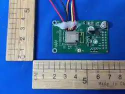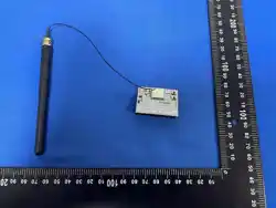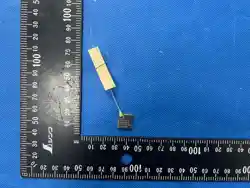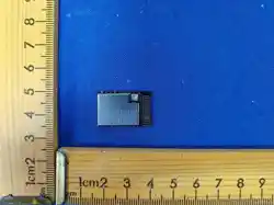

ye
PRODUCT SPECIFICATION
6220HL-IF
Wi-Fi Single-band 1x1 + Bluetooth 4.2
Combo Module
Version:v1.0
Customer:
Customer P/N:
Signature:
Date:
Office: 14 th floor, Block B, phoenix zhigu, Xixiang Street, Baoan District, Shenzhen
Factory: NO.8, Litong RD., Liuyang Economic & Technical Development Zone, Changsha, CHINA
TEL: +86-755-2955-8186 Website: www.fn-link.com
FN-LINK TECHNOLOGY LIMITED 1
FN-LINK TECHNOLOGY LIMITED 2
6220HL-IF Module Datasheet
Ordering
Information
Part NO.
Description
FG6220HLIF-00
RTL8720CF-VA2-CG 802.11
b/g/n/,33*18mm,UART/1T1R+BLE4.2 板载天线+ipex 头
FN-LINK TECHNOLOGY LIMITED 3
6220HL-IF
CONTENTS
1. General Description
............................................................................................................
5
1.1 Introduction
.......................................................................................................................
5
1.2 Description ........................................................................................................................5
2. Features .................................................................................................................................. 6
3. Block Diagram ....................................................................................................................... 7
4. General Specification .......................................................................................................... 7
4.1 WI-FI Specification ............................................................................................................. 7
4.2 Bluetooth Specification .................................................................................................. 8
6. Pin Definition
.........................................................................................................................
9
6.1 Pin Outline ........................................................................................................................ 9
6.2 Pin Definition details ..................................................................................................... 10
7. Electrical Specifications .................................................................................................. 11
7.1 Power Supply DC Characteristics .............................................................................. 11
7.2 Power Consumption ...................................................................................................... 11
7.3 Power On Sequence ..................................................................................................... 12
7.4 Interface Circuit time series ........................................................................................ 12
7.4.1 Resume from Standby ............................................................................................. 12
7.4.2 Shutdown Sequence ................................................................................................ 13
8. Size reference ...................................................................................................................... 13
8.1 Module Picture ............................................................................................................... 13
8.2 Marking Description ...................................................................................................... 13
8.3 Layout Recommendation ............................................................................................. 15
9. The Key Material List ......................................................................................................... 16
10. Reference Design ............................................................................................................. 16
11. Recommended Reflow Profile
......................................................................................
17
12. RoHS compliance ............................................................................................................. 17
13. Package
...............................................................................................................................
17
13.1 Reel .............................................................................................................................. 17
14. Moisture sensitivity ......................................................................................................... 18
6220HL-IF
FN-LINK TECHNOLOGY LIMITED 4
Revision History
Version
Date
Contents of Revision Change
Draft
Checked
Approved
V1.0
2023/11/21
New version
LXP
Zl
Qjp
6220HL-IF
FN-LINK TECHNOLOGY LIMITED 5
1. General Description
1.1 Introduction
622 0HL-IF is an embedded high- performance Wi-Fi+BLE module, which adopts the Realtek XMC1R - CGT
chip platform solution. 6220NM-IN is an integrated PCB on-board antenna and an external false. The module
is mainly applicable to smart home appliances, home automation, industrial Internet and other Internet of
Things applications.
1.2 Description
Model Name
6220HL-IF
Product Description
Support Wi-Fi/Bluetooth functionalities
Dimension
L x W x H: 33 x 18 x 3.12 mm
Wi-Fi Interface
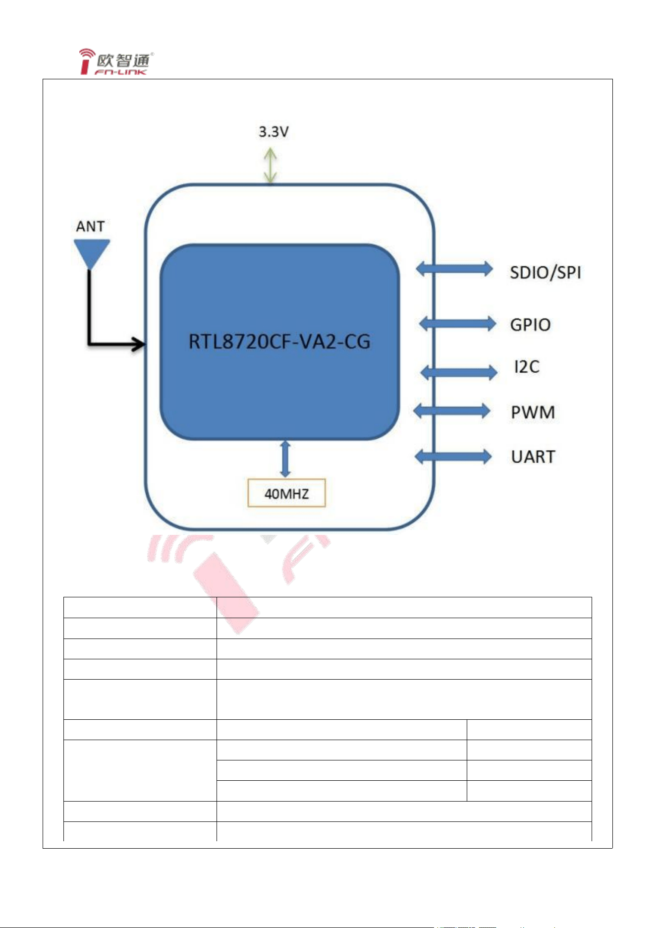
SDIO device, SPI, UART, GPIO, PWM, I2C
Operating temperature
-20 °C to +85 °C
Storage temperature
-40 °C to 125 °C
6220HL-IF
FN-LINK TECHNOLOGY LIMITED 6
2. Features
General
Complete 802. 11n solution for 2.4GHz band
CMOS MAC, Baseband PHY, and RF in a single chip for 802. 11b/g/ n compatible WLAN
Compatible with 802. 11n specification
Backward compatible with 802. 11b/g devices while operating in 802. 11n mode
Maximum data rate 26Mbps in 802.11g and 65Mbps in 802. 11n
65 Mbps receive PHY rate and 65 Mbps transmit PHY rate using 20 MHz bandwidth
802. 11i (WPA, WPA2). Open, shared key, and pair-wise key authentication services
Host Interface
Support SDIO 2.0 High Speed mode
Bluetooth Features
Bluetooth Smart Ready (Bluetooth Low Energy) supporting BT4.2 BQB
6220HL-IF
FN-LINK TECHNOLOGY LIMITED 7
3. Block Diagram
4. General Specification
4.1 WI-FI Specification
Feature
Description
WLAN Standard
IEEE 802.11 b/g/n Wi-Fi compliant
Frequency Range
2.400 GHz ~ 2.4835 GHz (2.4 GHz ISM Band)
Number of Channels
2.4GHz:Ch1 ~ Ch14
Modulation
WiFi:DSSS DBPSK/DQPSK/CCK
OFDM BPSK/QPSK/16 QAM/64 QAM
Test Items
Typical Value
EVM
Output Power
802. 11b /11Mbps : 17dBm ± 2 dB
EVM ≤ -10dB
802.11g /54Mbps : 15dBm ± 2 dB
EVM ≤ -25dB
802. 11n /MCS7 : 14dBm ± 2 dB
EVM ≤ -28dB
Spectrum Mask
Meet with IEEE standard
Freq. Tolerance
±20ppm
6220HL-IF
FN-LINK TECHNOLOGY LIMITED 8
SISO Receive Sensitivity
(11b,20MHz) @8% PER
- 1Mbps PER @ -91 dBm
≤-83
- 2Mbps PER @ -89 dBm
≤-80
- 5.5Mbps PER @ -87 dBm
≤-79
- 11Mbps PER @ -85 dBm
≤-76
SISO Receive Sensitivity
(11g,20MHz) @10% PER
- 6Mbps PER @ -87 dBm
≤-85
- 9Mbps PER @ -86 dBm
≤-84
- 12Mbps PER @ -84 dBm
≤-82
- 18Mbps PER @ -82 dBm
≤-80
- 24Mbps PER @ -79 dBm
≤-77
- 36Mbps PER @ -75 dBm
≤-73
- 48Mbps PER @ -71 dBm
≤-69
- 54Mbps PER @ -70 dBm
≤-68
SISO Receive Sensitivity
(11n,20MHz) @10% PER
- MCS=0 PER @ -87 dBm
≤-85
- MCS=1 PER @ -84 dBm
≤-82
- MCS=2 PER @ -82 dBm
≤-80
- MCS=3 PER @ -79 dBm
≤-77
- MCS=4 PER @ -75 dBm
≤-73
- MCS=5 PER @ -71 dBm
≤-69
- MCS=6 PER @ -70 dBm
≤-68
- MCS=7 PER @ -69 dBm
≤-67
Maximum Input Level
802. 11b : -8 dBm
802.11g/n : -20 dBm
4.2 Bluetooth Specification
Feature
Description
General Specification
Bluetooth Standard
Bluetooth V4.2
Antenna Reference
Small antennas with 0~2 dBi peak gain
Frequency Band
2400 MHz ~ 2483.5 MHz
Number of Channels
40 channels
Modulation
GFSK
RF Specification
Min
(dBm)
Typical(dBm)
Max
(dBm)
6220HL-IF
FN-LINK TECHNOLOGY LIMITED 9
Output Power (Class 1)
2.5
4.5
6.5
Sensitivity @ BLE=1%
for GFSK (1Mbps)
-89
Maximum Input Level
GFSK (1Mbps):-20dBm
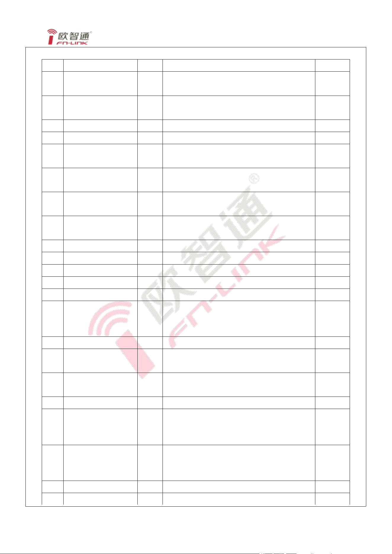
6. Pin Definition
6.1 Pin Outline
< TOP VIEW >
6220HL-IF
FN-LINK TECHNOLOGY LIMITED 10
6.2 Pin Definition details
NO.
Name
Type
Description
Voltage
1
GPIOA_0
I/O
JTAG_ CLK/ UART1_ IN/ PWM0, power on requires
low level: normal start mode
2
GPIOA_ 1
I/O
JTAG_TMS/UART1_ OUT/PWM1, power on requires
low level: EFUSE normal import mode
GPIOA_ 1
3
GPIOA_2
I/O
JTAG_TDO/UART1_ IN/SPI_CS/I2C_SCL/PWM2
4
GPIOA_4
I/O
JTAG_TRST/ UART1_CTS/ SPI_MOSI/ PWM4
5
GPIOA_7
I/O
UART0_IN/ PWM7
Communication RX
6
GPIOA_8
I/O
UART0_IN/ PWM8
Communication RX
7
GPIOA_ 14/SDIO_INT
I/O
SDIO_INT/ UART0_ OUT/ PWM2
Communication TX
8
GPIOA_ 13
I/O
UART0_IN/ PWM7
Communication RX
9
CHIP_EN
Module enable
10
GPIOA_9
I/O
11
GPIOA_ 10
I/O
12
GPIOA_ 11
I/O
13
GPIOA_ 12
I/O
14
VDD_IN
Power,
The maximum output current of the external power
supply is recommended to be 500 mA and above.
15
GND
Ground connections
16
GPIOA_ 19/SD_D0
I/O
SD_D0/SPI_M_D0/UART2_CTS/SPI_MOSI/I2C_SC
L/PWM7
17
GPIOA_20/SD_D 1
I/O
SD_D 1/SPI_M_D 1/UART2_RTS/SPI_MISO/I2C_SD
A/PWM0
18
GPIOA_ 17/SD_CMD
I/O
SD_CMD/SPI_M_D2/PWM5
19
GPIOA_ 16/SD_D3
I/O
SD_D3/SPI_M_CLK/UART2_OUT/SPI_SCL/
I2C_SDA/ PWM4
Commissioning TX
20
GPIOA_ 15/SD_D2
I/O
SD_D2/SPI_M_CS/UART2_IN/SPI_CS/I2C_SCL/
PWM3
Commissioning RX
21
GPIOA_ 18/SD_CLK
I
SD_CLK/SPI_M_D3/PWM6
22
GND
-
Ground connections
6220HL-IF
P:POWER I:INPUT O:OUTPUT
explain:
GPIO0 power-on instant, do not pull high, or enter the down load mode.
Module startup configuration table:
CHIP_EN
GPIOA_0
GPIOA_ 13
Normal operation mode
1
0
0 OR 1
URAT download mode
0->1
1
1
GPIO1 power-on instant, do not pull high, otherwise the efuse configuration will fail to import and affect
the normal operation of the module.
GPIO23 power-on instant, do not pull high, otherwise it will affect the normal operation of the module
7. Electrical Specifications
7.1 Power Supply DC Characteristics
MIN
TYP
MAX
Unit
Operating Temperature
-20
25
85
deg.C
VCC33
3.0
3.3
3.6
V
7.2 Power Consumption
model
Mcu status
describe
TYP
Unit
shutdown
10
uA
Deep sleep
30
uA
Standby
Power-gated
200
uA
Sleep
Clock-gated
WLAN off
450
uA
MCU Active
9
mA
WLAN on(beacon only)
MCU sleep
58
mA
WLAN asoc idle(2.4G),RF ON
MCU sleep
DTIM=1
3
mA
WLAN asoc idle(2.4G),RF ON
MCU sleep
DTIM=3
2
mA
BT active+WLAN active
MCU sleep
60
mA
FN-LINK TECHNOLOGY LIMITED 11
6220HL-IF
FN-LINK TECHNOLOGY LIMITED 12
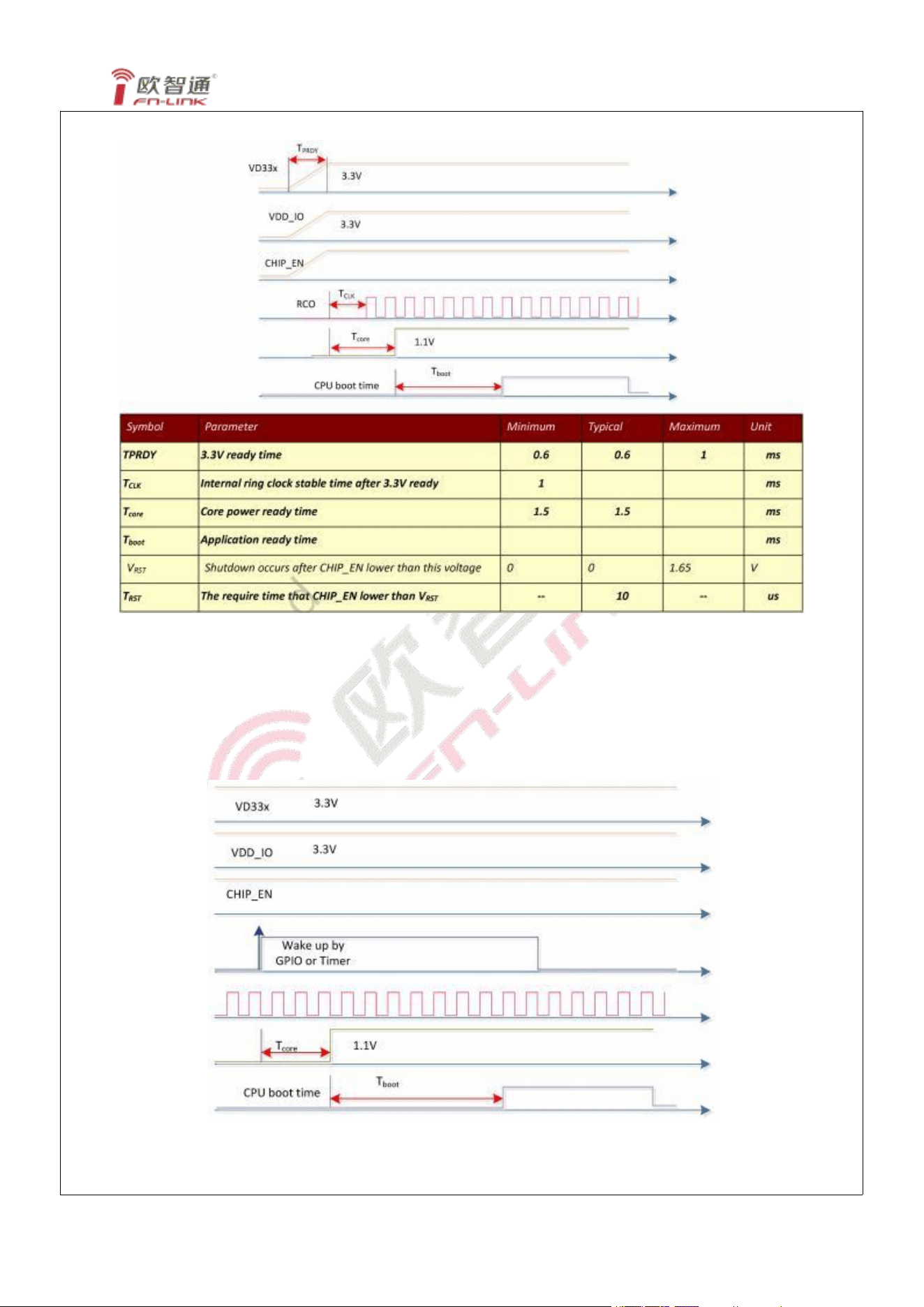
7.3 Power On Sequence
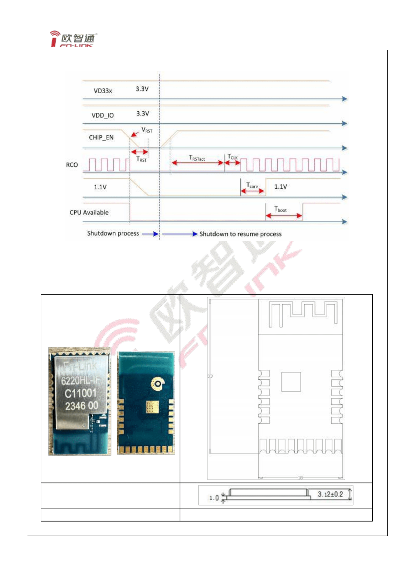
7.4 Interface Circuit time series
7.4.1 Resume from Standby
6220HL-IF
7.4.2 Shutdown Sequence
8. Size reference
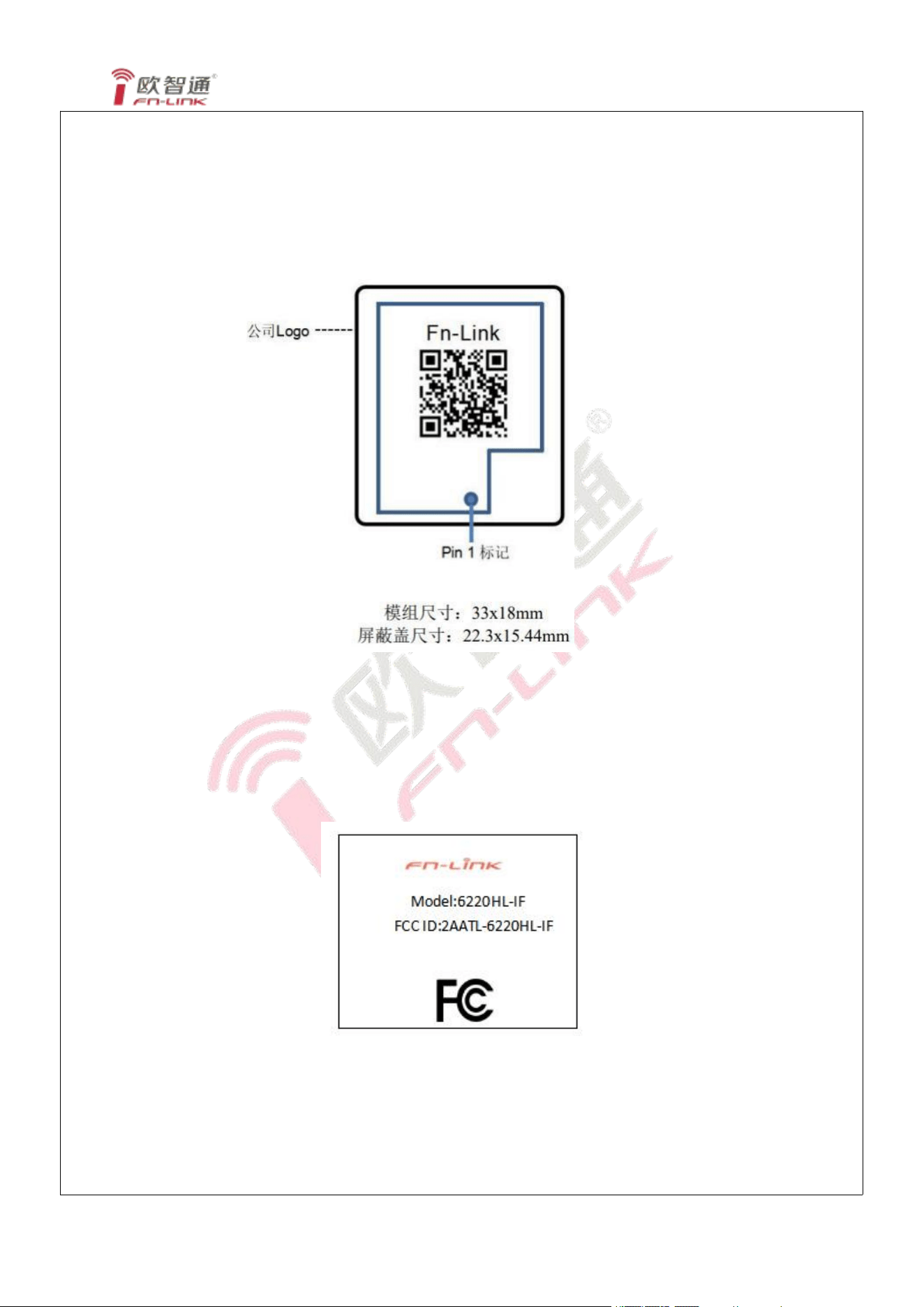
8.1 Module Picture
L x W : 33 x 18 (±0.2) mm
2.37g
Note
:
Module Picture the actual shipment shall prevail
FN-LINK TECHNOLOGY LIMITED 13
H:3.12(±0.2) mm
Weight
6220HL-IF
FN-LıNĸ τECHNOLOGY LıMıτED 14
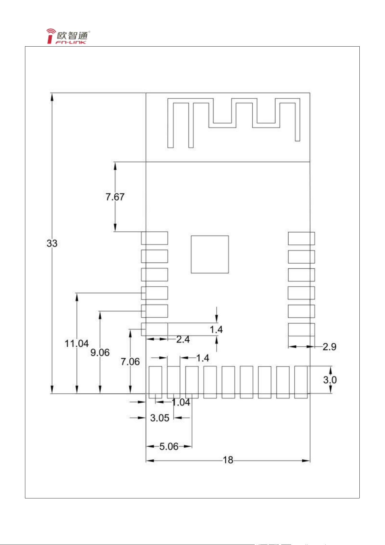
8.2 Marking Description
6220HL-IF
FN-LıNĸ τECHNOLOGY LıMıτED 15
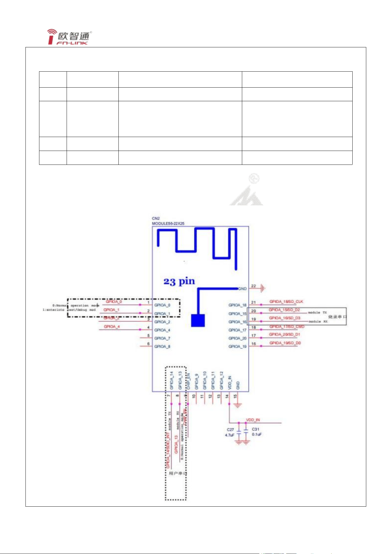
8.3 Layout Recommendation
6220HL-IF
FN-LINK TECHNOLOGY LIMITED 16
9. The Key Material List
Item
Part Name
Description
Manufacturer
1
Chipset
RTL8720CF-VA2-CG QFN40,5x5mm
Realtek
2
PCB
6220HL-IF-V2.0 蓝油 白字,FR4,4 层通
孔 , 无 卤 TG150, 化 金 2 μ ” , 16 连
片, 18x33x1.0mm
XY-PCB,KX-PCB,SL-PCB,Sunlord
3
Crystal
2016 40MHZ, 12PF, ± 10PPM
TST,HOSONIC,TKD,ECEC,JWT
4
Shielding
6220HL-IF Shielding
信太,精力通
10. Reference Design
6220HL-IF
FN-LINK TECHNOLOGY LIMITED 17
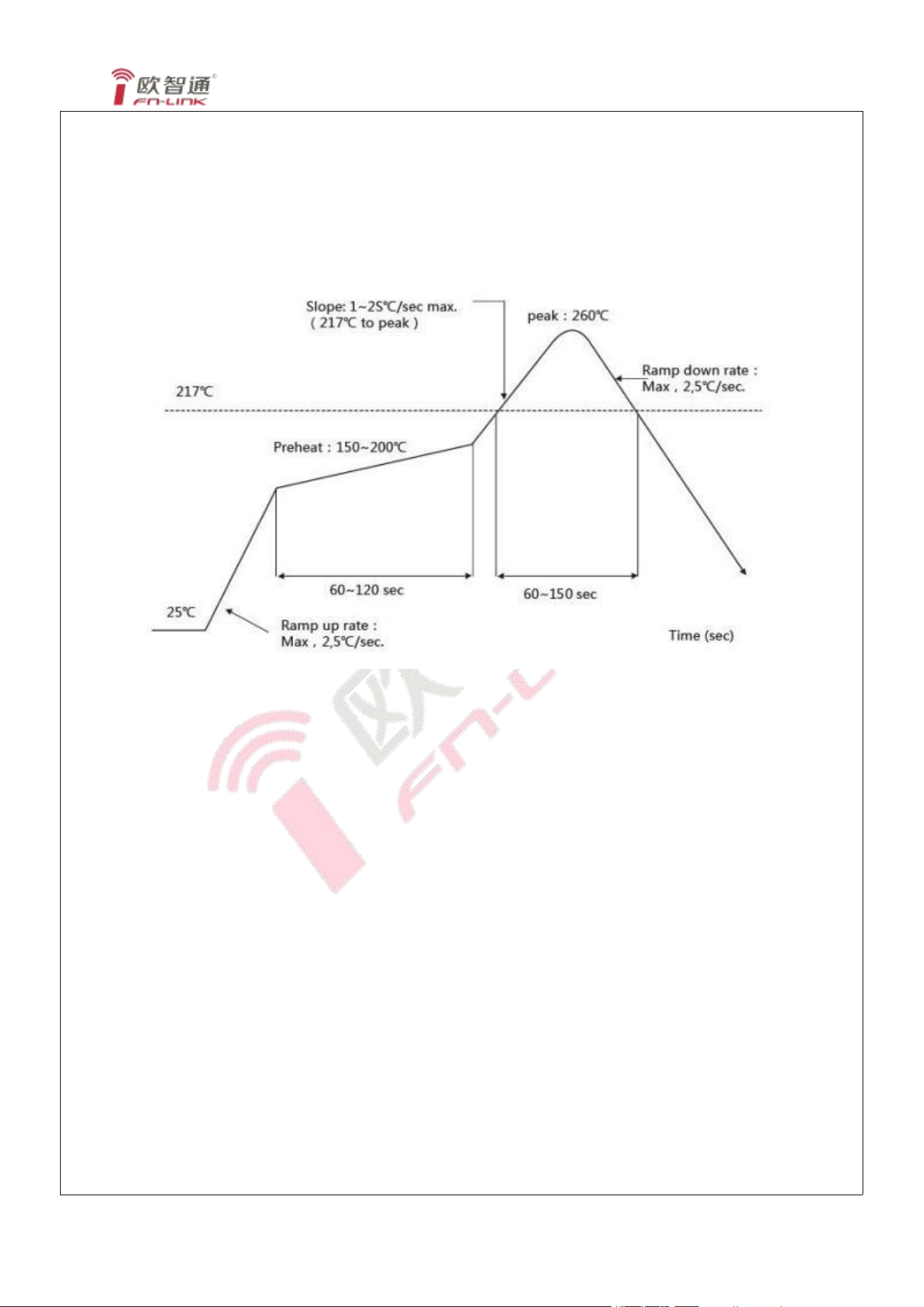
11. Recommended Reflow Profile
Referred to IPC/JEDEC standard.
Peak Temperature : <260°C
Number of Times : ≤2 times
12. RoHS compliance
All hardware components are fully compliant with EU RoHS directive
13. Package
13.1 Reel
TBD
6220HL-IF
FN-LINK TECHNOLOGY LIMITED 18
14. Moisture sensitivity
The Modules is a Moisture Sensitive Device level 3, in according with standard IPC/JEDEC
J-STD-020, take care
all the relatives requirements for using this kind of components.
Moreover, the customer has to take care of the following conditions:
a) Calculated shelf life in sealed bag: 12 months at <40 °C and <90% relative humidity (RH)
b) Environmental condition during the production: 30 °C / 60% RH according to IPC/JEDEC J-STD-033A
paragraph 5
c) The maximum time between the opening of the sealed bag and the reflow process must be 168 hours if
condition
d) “IPC/JEDEC J-STD-033A paragraph 5.2” is respected
e) Baking is required if conditions b) or c) are not respected
f) Baking is required if the humidity indicator inside the bag indicates 10% RH or more
The Module is designed to comply with the FCC statement. FCC ID is 2AATL-6220HL-IF. The host system
using Module, should have label indicated it contain modular’s FCC ID: 2AATL-6220HL-IF. This radio module
must not installed to collocate and operating simultaneously with other radios in host system additional testing
and equipment authorization may be required to operating simultaneously with other radio.
The Module and its antenna must not be co-located or operating in conjunction with any other transmitter or
antenna within a host device.
The modular must be installed in the host that assign by Company name: FN-LINK TECHNOLOGY LIMITED,
Model no.: 6220HL-IF if other host types used would need further evaluation and possible C2PC if they are not
significantly similar to the one tested The WIFI Module is designed for a compact PCB design. It should be
installed and operated with host or other minimum distance of 20 centimeters between the radiator and your
body." To comply with FCC regulations limiting both maximum RF output power and human exposure to RF
radiation, the maximum antenna gain including cable loss in a mobile-only exposure condition must not exceed
1.58 dBi in 2.4G. The module uses PCB antenna, the antenna is sold with the module.
Notice to OEM integrator
6220HL-IF
FN-LINK TECHNOLOGY LIMITED 18
The end user manual shall include all required regulatory information/warning as show in this manual. The
OEM integrator is responsible for testing their end-product for any additional compliance requirements required
with this module installed. If the final product contains circuits of other FCC PART 15 Subparts, the final host
product still requires Part 15 Subpart B compliance testing with the modular transmitter installed The intended
use is generally not for the general public. It is generally for industry/commercial use. The connector is within
the transmitter enclosure and can only be accessed by disassembly of the transmitter that is not normally
required, the user has no access to the connector. Installation must be controlled. Installation requires special
training.
This device complies with Part 15 of the FCC Rules.
This equipment should be installed and operated with a minimum distance of 20 cm between the radiator and
your body.
2.2
This module has been assessed against the following FCC rule parts: CFR 47 FCC Part 15 C (15.247. DTS). lt
is applicable to the modular transmitter
2.3
This radio transmitter Module has been approved by Federal Communications Commission to operate with the
antenna types listed below, with the maximum permissible gain indicated. Antenna types not included in this list
that have a gain greater than the maximum gain indicated for any type listed are strictly prohibited for use with
this device.
The concrete contents to check are the following three points.
1) Maximum antenna gains are shown in item 2.7 below.
2) Should be installed so that the end user cannot modify the antenna
3) Feed line should be designed in 50ohm
Fine-tuning of return loss etc. can be performed using a matching network.
The antenna shall not be accessible for modification or change by the end user.
2.4
The module complies with FCC Part 15.247 and apply for Single module approval.
2.5
Trace antenna designs: applicable.
Any deviation(s) from the defined parameters of the antenna trace, as described by the instructions, require
that the host product manufacturer must notify the module grantee that they wish to change the antenna trace
design. in this case, a Class ll permissive change application is required to be filed by the grantee, or the host
manufacturer can take responsibility through the change in FCC lD (new application) procedure followed by a
Class ll permissive change application.
The device must be professionally installed.
The intended use is generally not for the general public.
It is generally for industry/commercial use.
The connector is within the transmitter enclosure and can only be accessed by disassembly of the transmitter
that is not normally required.
The user has no access to the connector.
Installation must be controlled.
Installation requires special training.
2.6
This equipment complies with FCC radiation exposure limits set forth for an uncontrolled environment. This
equipment should be installed and operated with a minimum distance of 20cm between the radiator & your
body. This transmitter must not be co-located or operating in conjunction with any other antenna or transmitter.
2.7
The following antennas have been certified for use with this module.
Only antennas of the same type with equal or lower gain may also be used with this module.
Other types of antennas and/or higher gain antennas may require the additional authorization for operation.
The installer should use unique antenna connector and Antenna types not included in this list that have a gain
greater than the maximum gain indicated for any type listed are strictly prohibited for use with this device. The
6220HL-IF
FN-LINK TECHNOLOGY LIMITED 18
manufacturer of module will inform installer to meet with the FCC part 15.203 in the warning part.
Antenna Specification list below:
BLE/2.4G WIFI:
Antenna type: PCB Antenna
The max antenna gain (in dBi):1.58 dBi
2.8
Please notice that if the FCC identification number is not visible when the module is installed inside another
device, then the outside of the device into which the module is installed must also display a label referring to
the enclosed module. This exterior label can use wording such as "Contains FCC ID: 2AL6K-BLM8852BP2 ";
any similar wording that expresses the same meaning may be used.
2.9
Testing of the host product with all the transmitters installed - referred to as the composite investigation test- is
recommended, to verify that the host product meets all the applicable FCC rules. The radio spectrum is to be
investigated with all the transmitters in the final host product functioning to determine that no emissions exceed
the highest limit permitted for any one individual transmitter as required by Section 2.947(f). The host
manufacturer is responsible to ensure that when their product operates as intended it does not have any
emissions present that are out of compliance that were not present when the transmitters were tested
individually.
If the modular transmitter has been fully tested by the module grantee on the required number of channels,
modulation types, and modes, it should not be necessary for the host installer to re-test all the available
transmitter modes or settings. lt is recommended that the host product manufacturer, installing the modular
transmitter, perform some investigative measurements to confirm that the resulting composite system does not
exceed the spurious emissions limits or band edge limits (e.g., where a different antenna may be causing
additional emissions).
The testing should check for emissions that may occur due to the intermixing of emissions with the other
transmitters, digital circuitry, or due to physical properties of the host product (enclosure). This investigation is
especially important when integrating multiple modular transmitters where the certification is based on testing
each of them in a stand-alone configuration.
2.10
Any company of the host device which install this modular should perform the test of radiated & conducted
emission and spurious emission etc. according to FCC Part 15C: 15.247 and15.209 & 15.207, part 15B: class
B requirement, only if the test result comply with FCC part 15C: 15.247, 15B class B requirement. Then the
host can be sold legally.
The host product manufacturer is responsible for compliance to any other FCC rules that apply to the host not
covered by the modular transmitter grant of certification, lf the grantee markets their product as being Part 15
Subpart B compliant (when it also contains unintentional-radiator digital circuity), then the grantee shall provide
a notice stating that the final host product still
requires Part 15 Subpart B compliance testing with the modular transmitter installed.
FCC Statement
1. This device complies with Part 15 of the FCC Rules. Operation is subject to the following two conditions:
(1)This device may not cause harmful interference.
(2)This device must accept any interference received, including interference that may cause undesired
operation.
2. Changes or modifications not expressly approved by the party responsible for compliance could void the
user’s authority to operate the equipment.
Note: This equipment has been tested and found to comply with the limits for a class B digital device, pursuant
to Part 15 of the FCC Rules. These limits are designed to provide reasonable protection against harmful
interference in a residential installation.
This equipment generates uses and can radiate radio frequency energy and, if not installed and used in
accordance with the instructions, may cause harmful interference to radio communications. However, there is
no guarantee that interference will not occur in a particular installation. If this equipment does cause harmful
interference to radio or television reception, which can be determined by turning the equipment off and on, the
user is encouraged to try to correct the interference by one or more of the following measures:
6220HL-IF
FN-LINK TECHNOLOGY LIMITED 18
• Reorient or relocate the receiving antenna.
• Increase the separation between the equipment and receiver.
• Connect the equipment into an outlet on a circuit different from that to which the receiver is connected.
• Consult the dealer or an experienced radio/TV technician for help.
The device has been evaluated to meet general RF exposure requirement. This equipment should be installed
and operated with a minimum distance of 20 cm between the radiator and your body.