Garage Door Kit 3
YS4906-UC_YS7706-UC
Installaon & User Guide
Rev 1.0
Garage Door Controller
SE T
Garage Door Sensor 2

Contents
In the Box ······· ····· · ·· · ·1······················ ····· ···················································· · ·
Important Noce ·······················································································2
Introducon ······························································································3
Set Up ·······································································································5
Installaon ································································································8
Using the YoLink App ················································································19
About YoLink Control ················································································29
Maintenance ···························································································35
Specificaons ··························································································40
Garage Door Controller Troubleshoong ···················································41
Garage Door Sensor 2 Troubleshoong ······················································42
Warning ··································································································43
···································································45Customer Service & Warranty
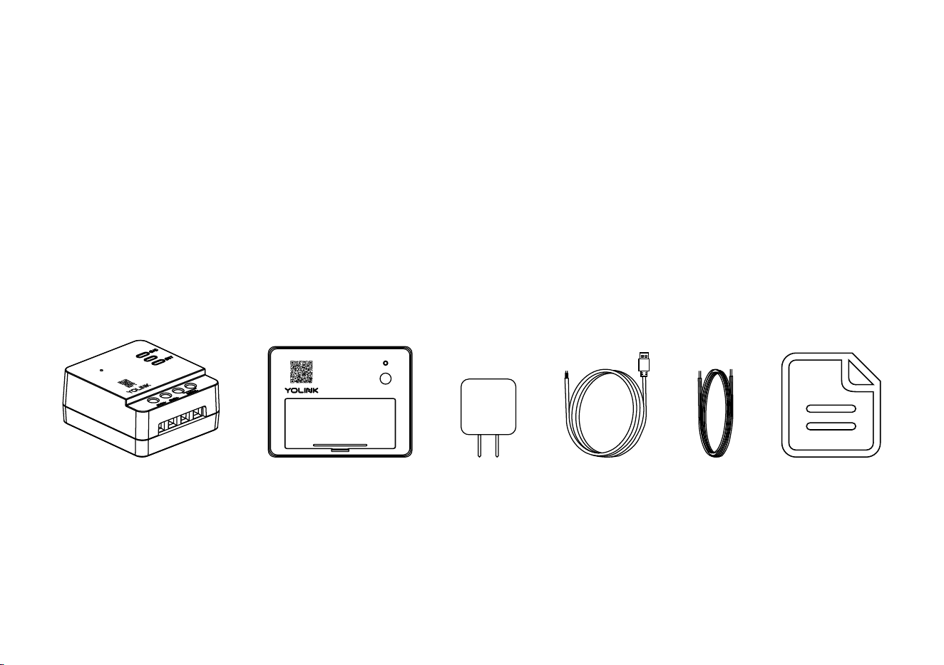
In the Box
A. Garage Door Controller
B. Garage Door Sensor 2
C. Power Adapter
D. USB Cable
Signal WireE.
F. Quick Start Guide
1
F.
E.
D.
C.
A.
B.
SET
Improper use of your garage door operator/opener can cause property damage and/or serious
injury or death. Install and use your Garage Door Kit 3 only as instructed in this manual
Allow the garage door operator/opener to complete opening or closing before opening/closing
with the controller or app
Do NOT allow children to use the door operator/opener or control it via the app without adult
supervision
Important Noce
If you are uncomfortable working with wiring or electricity, please consult or hire a qualified
electrician
Due to the different control circuit design of garage door opener, Garage Door Controller cannot
compable for all the garage door openers, visit yolink.net to check compability for your
garage door opener from the garage door opener list
2
Garage Door Sensor 2 is not compable for roller doors and slide or slide hinged doors, but only
compable for seconal doors or canopy garage doors
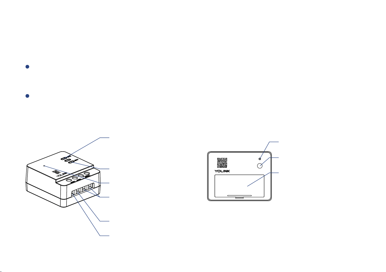
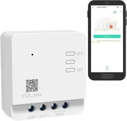
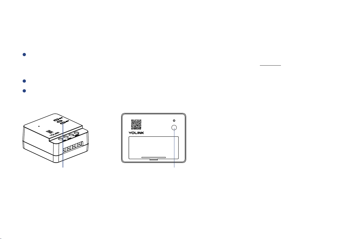
YoLink Smart Garage Door Kit 3 includes two products - YS4906-UC Garage Door Controller,
and YS7706-UC Garage Door Sensor 2
Introducon
O/C Buon
Press once to open / close
the garage door
SET Buon
Status LED
DC 5V+ (Input)
DC 5V- (Input)
Control Terminal
(Output)
3
Garage Door Sensor 2: Supervises the posion of your garage door, detecng when it is opened
or closed, and can send alerts or trigger an automaon based on the door opening, closing or
being le open too long
Garage Door Controller: Used for garage door operator or buon control, allows you to control
your garage door from the YoLink app, as well as via popular voice assistants like Alexa and Google
Assistants
SE T
Status LED
SET Buon
Baery Compartment
Includes two AAA
non-rechargeable baeries
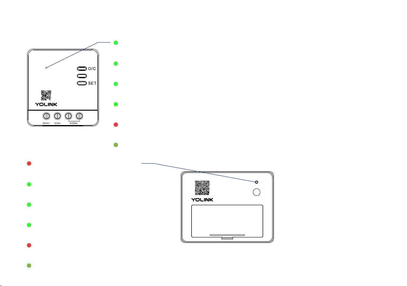
The LED light indicates the current status of the controller and sensor:
Green Once
Opening / Closing the door
Slow Blinking Green
Updang
Fast Blinking Red
Removing Connecon to YoLink System
Blinking Red And Green Alternately
Restoring to Factory Defaults
Fast Blinking Green
Establishing Connecon with YoLink System
Blinking Green
Connecng to Cloud
4
Red Once
Alert Mode (Door is Opened or Closed)
Slow Blinking Green
Updang
Fast Blinking Red
Removing Connecon to YoLink System
Blinking Red And Green Alternately
Restoring to Factory Defaults
Fast Blinking Green
Establishing Connecon with YoLink System
Blinking Green
Connecng to Cloud
SE T
Set Up
Set Up - First-Time YoLink Users (Exisng users proceed to Add Device, next page)
* Get ready: yourTo set up and use Garage D oor Kit, you will need an Apple iPhone or tablet that is iOS 9.0 or higher, or an Android phone or
tablet t hat is Android 4.4 or higher
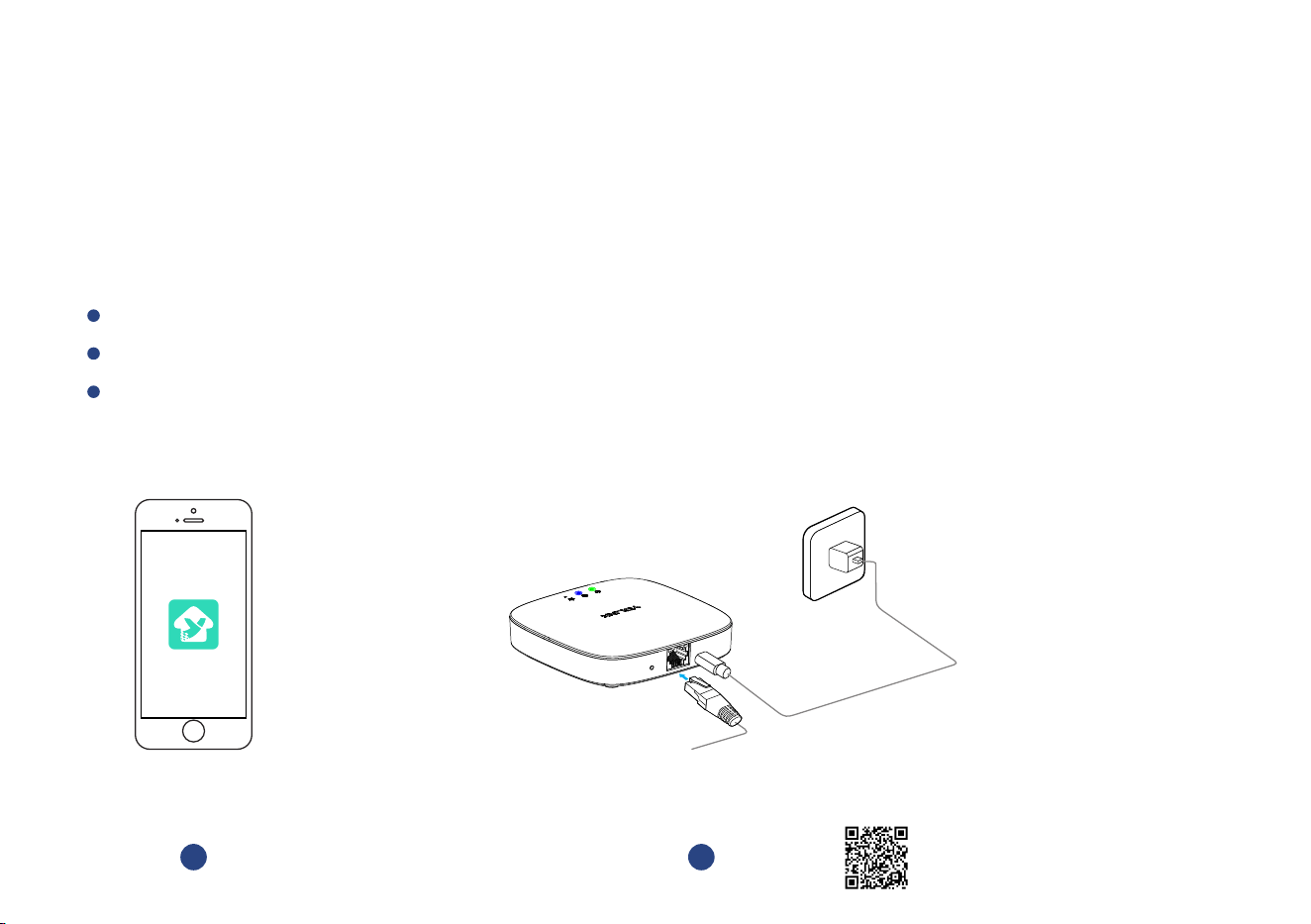
Follow the steps below to set up your Garage Door Kit via the YoLink app
Download YoLink app through Apple App Store or Google Play Store
Log in or create a new account if required
Download, and log
in to YoLink app
1
* Make sure your hub is connected to the
internet (green LED indicator is
blinking, blue LED indicator is
always on)
Power
Adapter
Hub
S
ET
Set up YoLink Hub
2
YoLink Hub is req uired to set up your . Please set up your YoLink Hub first Garage Door Kit
(refer to YoLink Hub manu al)
* Ethernet patch cable (included) to your network
(router, switch, etc.), recommended, but oponal.
Otherwise connect your Hub to your home Wi-Fi
network. Refer to the Hub set up manual for more
informaon:
YS1603-UC_User Guide
5
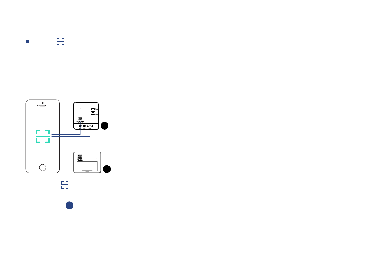
Add Device
Tap “ ” buon, then scan QR Code on the Garage Door Controller and Garage Door
Sensor 2 in turn
* Garage Door Controller. Aer pairing you will get real-me baery For the best user experience, we suggest you pair your Garage Door Sensor 2 with a
status of your Garage Door Sensor 2, signal level between Garage Door Controller or Garage Door Sensor 2 and the YoLink Hub, and real-me opened or
closed status of your garage door
* If you skip the pairing when adding the device, you can pair them later in the s page of Garage Door ControllerDetail
Tap “ ” buon
to add devices
1
1
2
6
SET
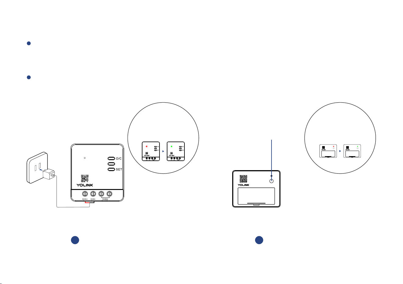
Turn on power of controller aer installaon (refer to Installaon secon on next page),
the Status LED will blink several mes (red, then green). The green LED indicates the device
is online and ready to use
Press the SET buon (on front of sensor) once, the Status LED will blink several mes (red,
then green). The green LED indicates the device is online and ready to use
Turn on power
aer installaon
2
* If the controller is powering on, press
the SET buon once, the Status LED will
blink green, your device is ready to use
* Status LED will blink
red once, then green several
mes(If device is working well
with connecon to the cloud, it will
blink red once only)
7
Press the SET buon (on
front of sensor) once
3
SET
Buon
SET
* Status LED will blink
red once, then green several
mes(If device is working well
with connecon to the cloud, it will
blink red once only)
SET SET
The are very difficult to relocate aer being affixed to the mounng controller and sensor
surface. Test your locaon before affixing the two devices to the surface. controller and sensor
Use masking or painters tape to secure the to the surface. Once you have controller and sensor
the temporarily mounted, test it out. With the app in hand, open or close controller and sensor
the door using app and observing the status of the sensor as shown on the app (Opened or
Closed). Oponally, you may set up your automaon (e.g. turn on a light when the door is
opened) to funconally test the status change of the door - proceed to the following steps for
informaon on creang automaons, then return to this step
Test the Controller and Sensor Locaon Before Installaon
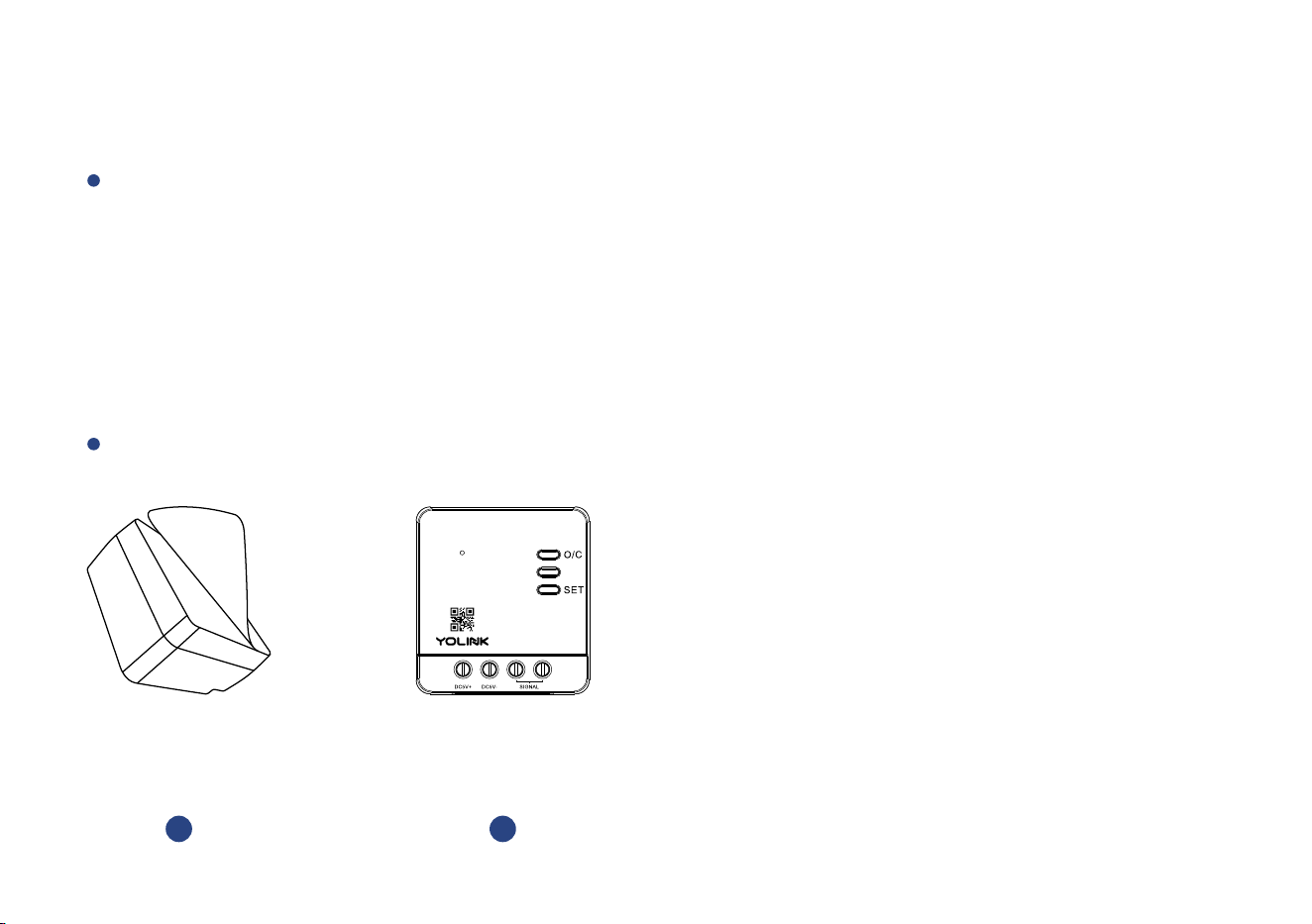
Garage Door Sensor 2 should be mounted on the top panel of garage door and keep the SET
buon at the top and the longer side parallel to the floor, otherwise the status of sensor shown
on the app (Opened or Closed) may be inaccurate
Installaon
Garage Door Controller and Sensor 2 are designed and intended for indoor use only!
8
Avoid allowing the controller and sensor to be exposed to strong impacts or vibraon
Please add the Garage Door Controller and Sensor 2 to the YoLink app before installaon
Remove the
protecve layer
1
Place the controller at the
desired locaon and press
firmly for at least 5 seconds
2
Get Ready to Install the Garage Door Controller
Sloed screwdriver - Number 3 mm may be required
Garage Door Controller
Before starng, choose the appropriate method for your installaon, connecng to your garage
door operator (typically on the ceiling of your garage) or the buon (typically on the wall). For
connecons to the operator (Method A) you may install the Garage Door Controller on the
garage door operator itself, near it on the ceiling, or on the wall, but please note the wiring
requirements: the Garage Door Controller requires the included power adapter, which requires
a 120V receptacle, which may or may not be available at your desired locaon. Also, power
wiring will be required between the Controller and the power adapter and signal wiring will be
required between the Controller and the operator
9
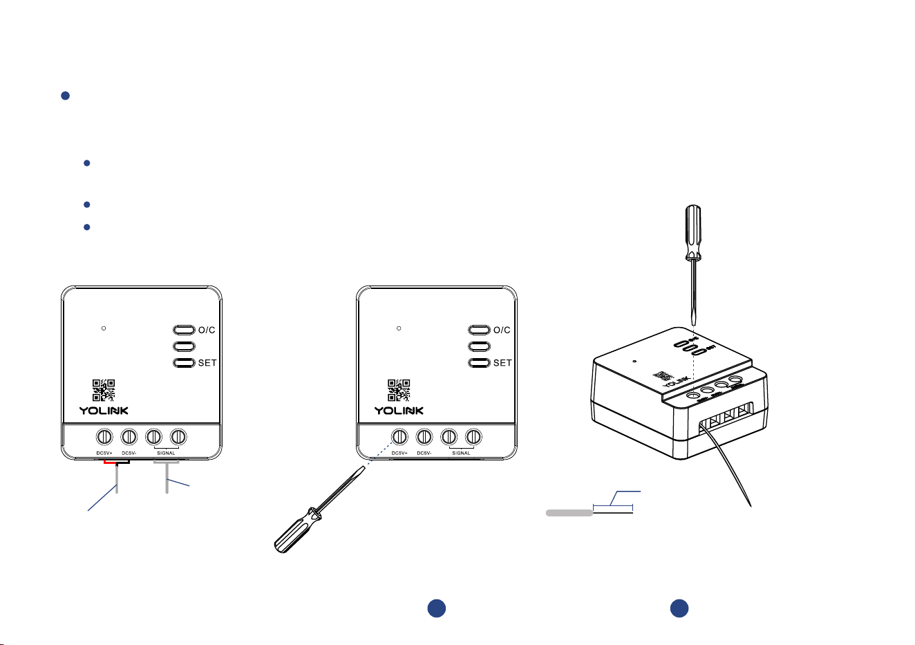
Begin Installaon:
Loosen the screw terminal using a 3 mm sloed screwdriver, connect the first wire to the
associated screw terminal on the Garage Door Controller; do the same for the remaining three
wires
Before connecng the wire to the terminal, ensure there is about 2/5 inch of bare wire visible (strip off
insulaon as needed)
Insert the wire into the terminal, then ghten the screw terminal
Gently tug on the wire to ensure a ght connecon
* For Method A, Connecng
to the Garage Door Operator,
proceed to step 5 on page 11
For Method B, Connecng
to the Garage Door Control
Buon, proceed to step 5 on
page 13
Signal wire
provided
From wire
provided with
the power adapter
Loosen screw terminal
3 4
Insert the associated (DC 5V+,
DC 5V- and Signal Wires) wires,
then ghten the screw terminal
2/5 inch
10
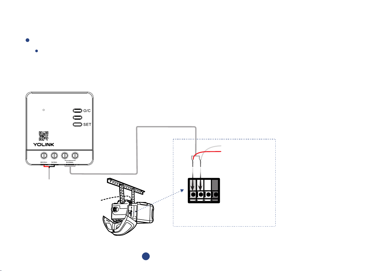
Method A: Connecng to the Garage Door Operator
From
Control Buon
Red
White
White
Grey
Locate the two control terminals on your garage door operator
5
Remove the exisng wires from the door operator, aer making a note (or taking a picture) of their locaons.
Twist* together one exisng wire to one (new) signal wire, install under the exisng wire's original terminal.
Repeat for the other exisng wire and new control wire
* If the wires are not twisted together, it is important to ensure both the old and new wires are both secured in place under the terminal, making
a good electrical connecon
11

Power on the controller
Power on the controller
6
Te st y o ur ga ra ge do o r op erato r a s you wo ul d
no r ma ll y u se it. I f i t i s n ot work i ng prope rl y,
do u b l e- ch ec k o r re- do s teps 3 t hro u gh 6 a s
ne e de d. Do no t p roc e ed to th e n ex t s t e p u n l
you r garage d o o r ope rato r wo rks as b e fore
12
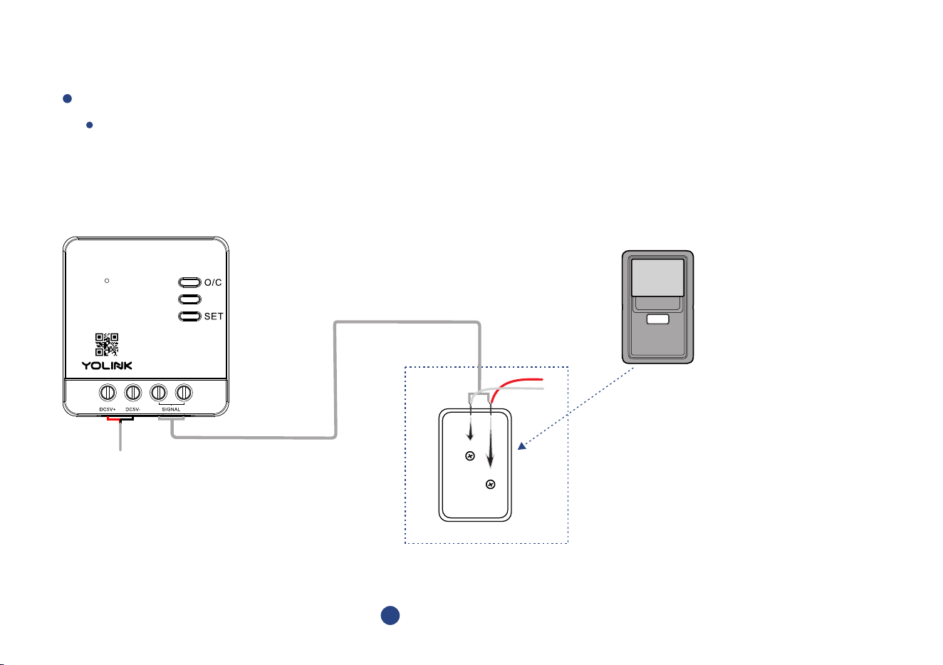
Method B: Connecng to the Garage Door Control Buon
Remove the exisng garage door control buon. Remove the exisng wires, aer making a note (or taking a
picture) of their locaons. Twist* together one exisng wire to one (new) signal wire, install under the exisng
wire's original terminal. Repeat for the other exisng wire and new control wire
* If the wires are not twisted together, it is important to ensure both the old and new wires are both secured in place under the terminal, making
a good electrical connecon
Locate the two control terminals on your garage door control buon
5
Control Buon
W
R
13
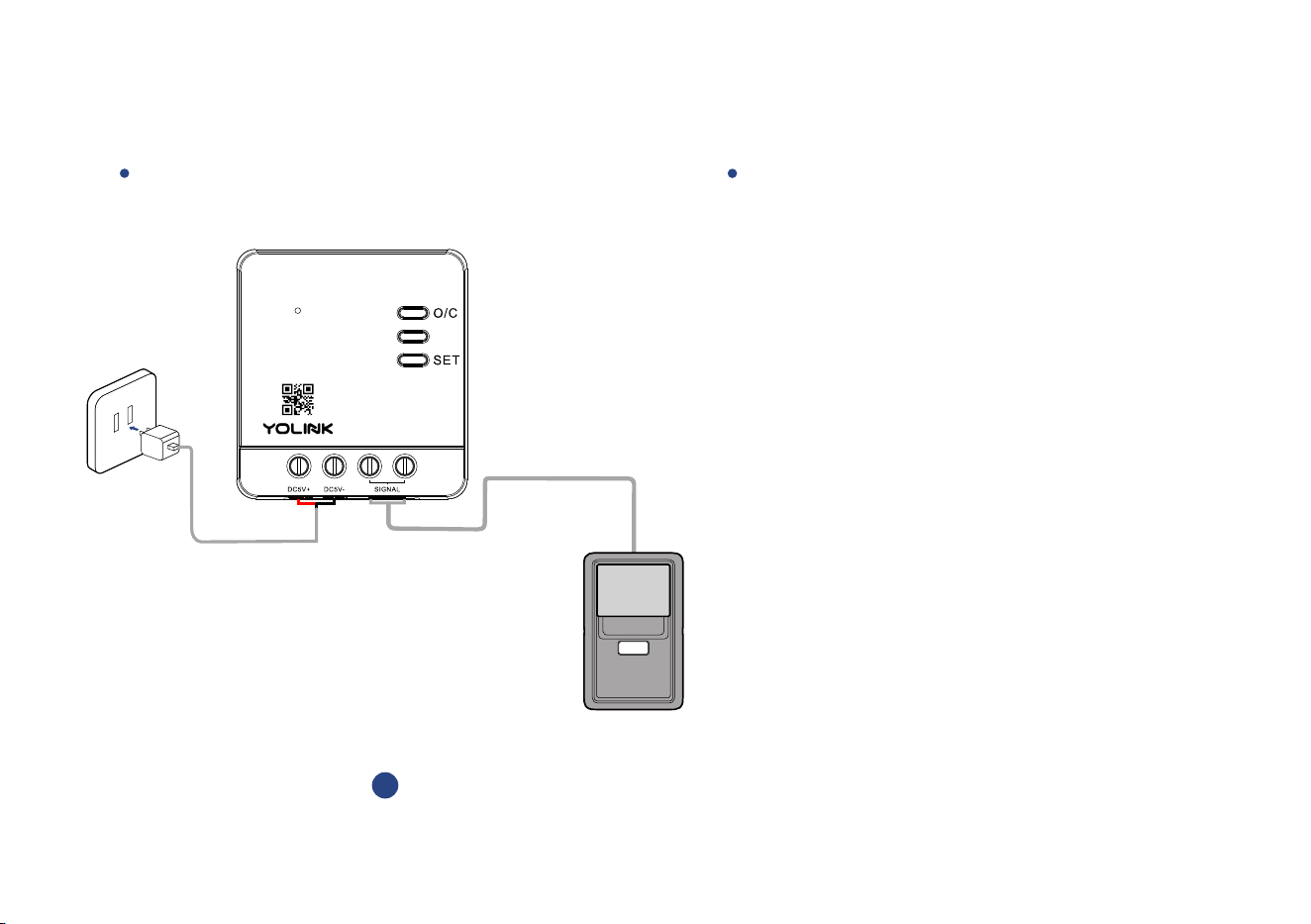
Power on the controller
Ver if y yo ur exisn g garag e doo r co ntro l le r
bu on func o n s n o r ma ll y. Ot he rw is e ,
do u b l e- ch ec k or re - d o step 5
Power on the controller
6
14
15
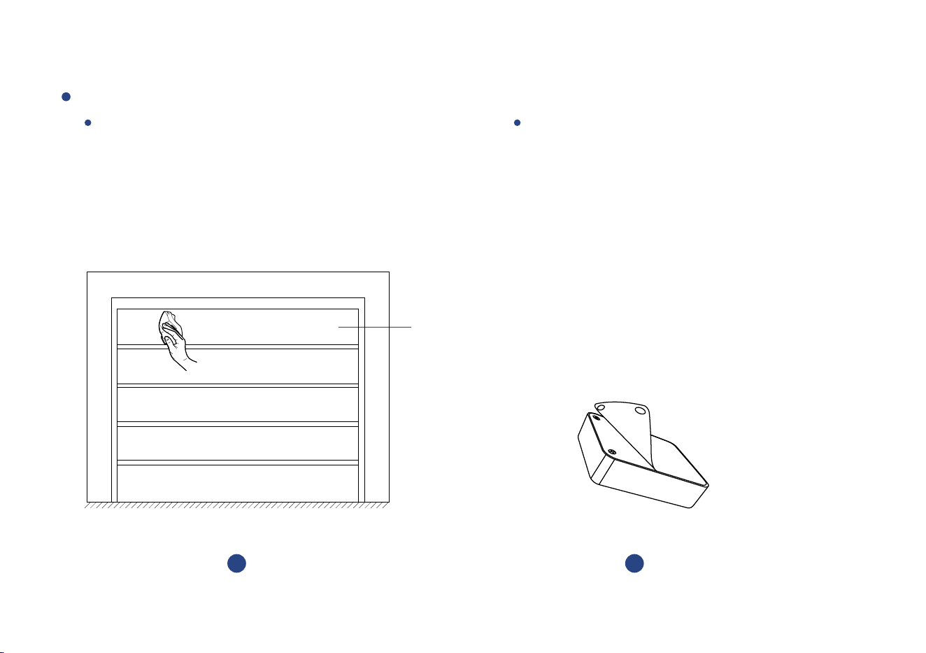
Garage Door Sensor 2
Top
Panel
Clean the installaon area
1
Remove the protecve layer
2
Method A: Install the Garage Door Sensor 2 with double-sided tape on the back of the device
Find a suitable area on the top panel (le or
right side suggested). Ensure the sensor will
not come in contact with moving parts of the
garage door operator/mechanism. Clean the
selected installaon area
Remove the protecve layer of the double-sided
tape
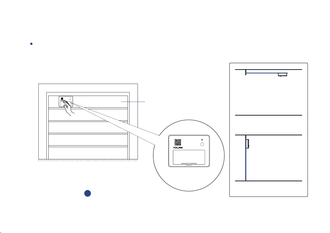
16
The door is closed
The door is opened
Top
Panel
Place the sensor at the desired locaon,
pressing firmly for at least 5 seconds
3
SET
SET
* Keep the longer side parallel to
the floor
Keep the SET buon of the Garage Door
Sensor 2 at the top and the longer side parallel
to the floor, press the sensor firmly to the door
for at least 5 seconds
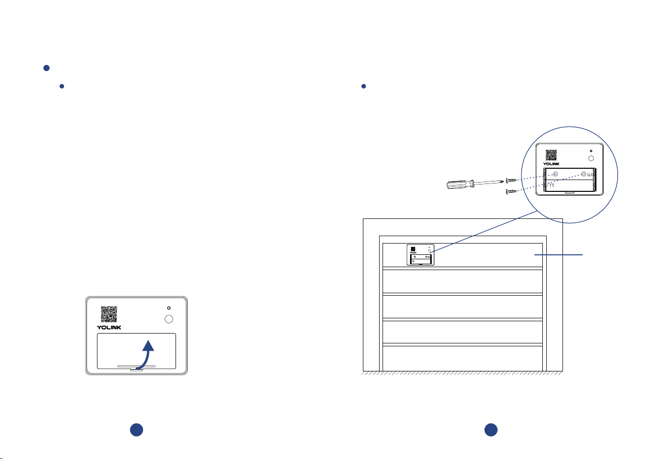
Method B: Mount the Garage Door Sensor 2 to the wall with screws (not included)
For wall-mounng, open the baery cover
and remove the screws to gain access to the
mounng holes on the back of the Sensor
Keep the longer side of the Garage Door Sensor 2
parallel to the floor, mount the sensor to the
top panel (le or right side suggested) of the
garage door using screws
2
Open the baery cover and
remove the baeries
SE T
3
Mount the Garage Door Sensor 2
Top
Panel
SET
SET
* Keep the longer side
parallel to the floor
17
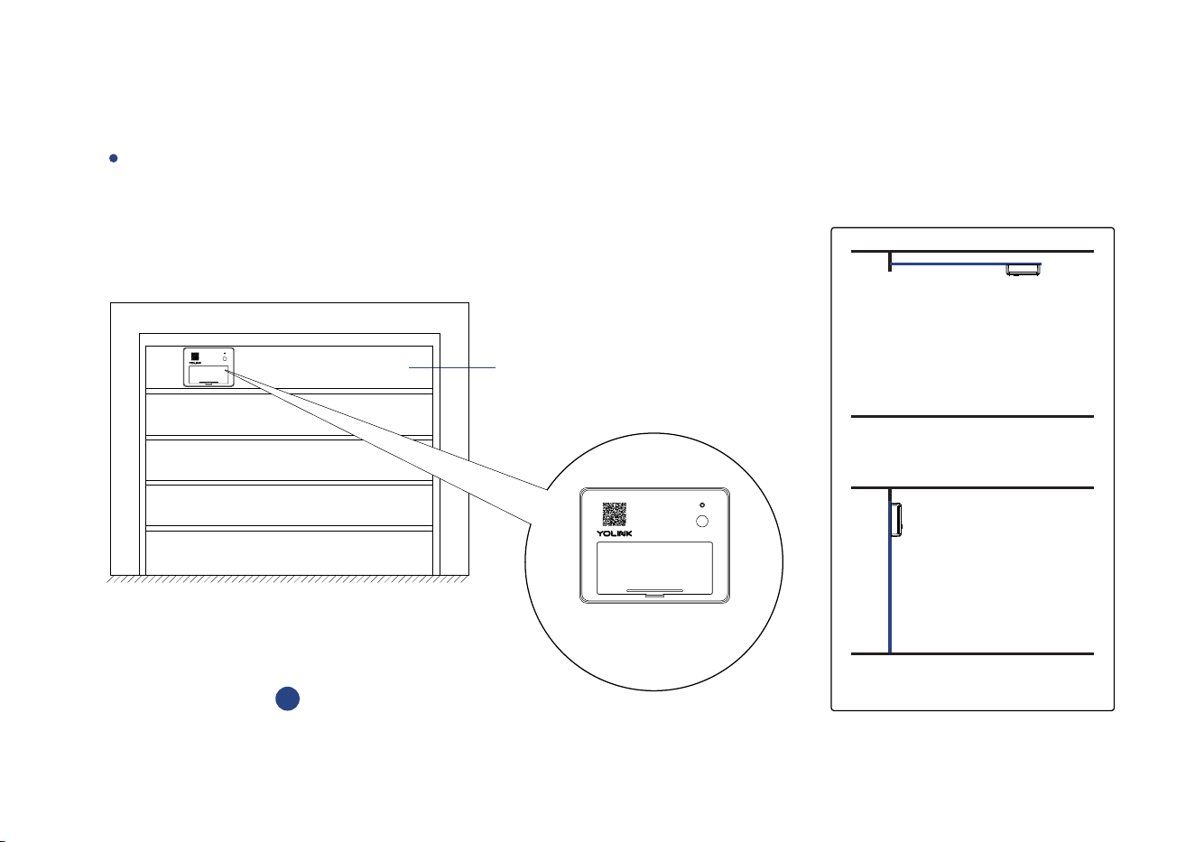
The door is closed
The door is opened
Top
Panel
Reinstall the baeries and
close the baery cover
3
SET
SET
Reinstall the baeries and close the baery cover
18
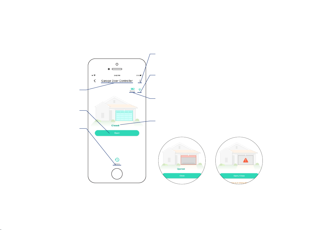
Using the YoLink App
Device page (Paired with a Sensor)
Connecon status
of controller/sensor and Hub
(the worse one)
Details
* Tap to go to Details page
(refer to page 20)
Device name
* Edit name on Details page
Real-me status:
Opened or closed or inaccurate status
Device history
Door opened and closed,
logged with date & me
* Tap to open/close the
garage door
Baery level
current baery level of sensor
* Shown red if replacement is required
* Garage door is closed * Inaccurate status of
garage door, double-check
the Installaon of garage
door sensor 2
19
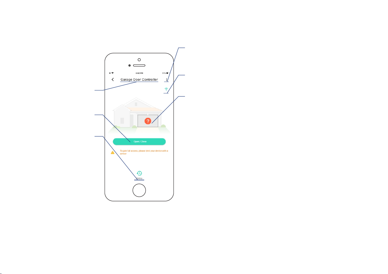
Device page (Controller Only)
Connecon status
of controller and Hub
Details
* Tap to go to Details page
(refer to page 22)
Device name
* Edit name on Details page
Unknown status of door
* Pair with a sensor to obtain
the status of door
Device history
Door controlled (no
status of door), logged
with date & me
* Tap to open/close the
garage door
20
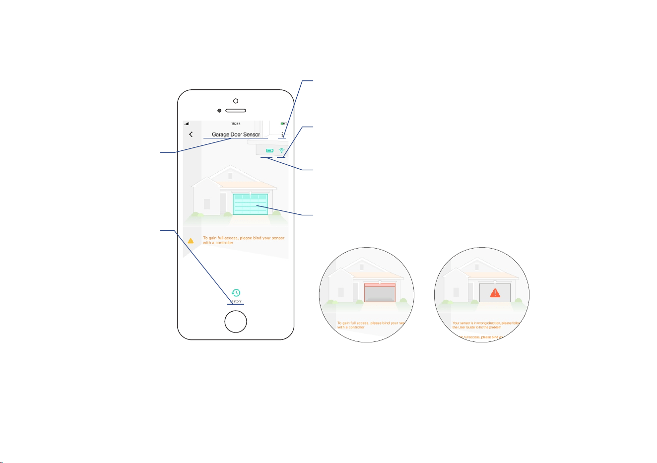
Device page (Sensor Only)
Connecon status
of sensor and Hub
Details
* Tap to go to Details page
(refer to page 23)
Device name
* Edit name on Details page
Device history
Door opened and closed,
logged with date & me
Real-me status:
Opened or closed or inaccurate status
Baery level
current baery level
* Shown red if replacement is required
* Garage door is closed * Inaccurate status of
garage door, double-check
the Installaon of garage
door sensor 3
21
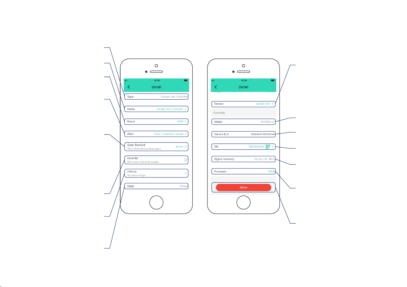
Details page (Paired with a Sensor)
Device history
Door opened and closed,
logged with date & me
Connecon status
of controller and Hub
Firmware version
* ” indicates a “#### ready now
new update is available (refer
to page )33
Add / remove
from favorites
* Tap to delete the device from
your YoLink account
Alert sengs
* Enable or disable alerts.
Default is set to Alert When
Door is Opened or Closed
Choose a room
for device
Device SN (unique)
Send noficaon
to you when the door
is le open for a set me
* Default is set to 30 minutes.
Aer the first noficaon, there
will be connuously noficaon
at a default interval of 30 minutes
Rename the device
Device status
Opened or closed or
inaccurate status
Device EUI (unique)
Device model
Tap to pair/unpair with
a sensor
* Sensor’s device name indicates
the controller is paired with a sensor.
Tap to go to Details page of sensor
(refer to next page)
22
Device type
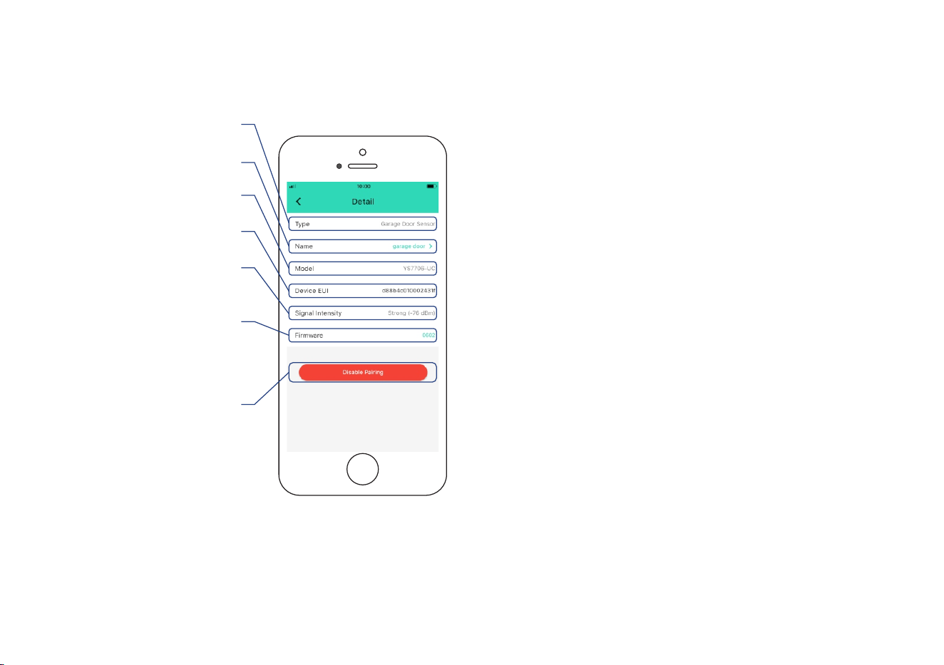
Details page of Sensor
23
* Tap to unpair the sensor
with the controller
Connecon status
of sensor and Hub
Device type
Device model
Firmware version
* ” indicates a “#### ready now
new update is available (refer
to page 33)
Rename the device
Device EUI (unique)
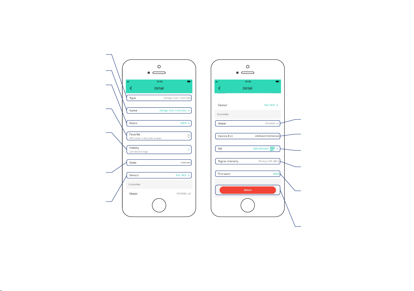
Details page (Controller Only)
Tap to pair/unpair
with a sensor
* Sensor’s device name
indicates the controller is
paired with a sensor
Connecon status
of controller and Hub
Firmware version
* ” indicates a “#### ready now
new update is available (refer
to page )34
Unknown status of door
* Pair with a sensor to obtain
the status of door
* Tap to delete the device from
your YoLink account
Add / remove
from favorites
Device type
Choose a room
for device
Device SN (unique)
Device history
Door controlled (no
status of door), logged
with date & me
Rename the device
Device EUI (unique)
Device model
24
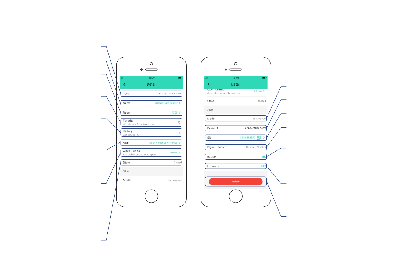
Details page (Sensor Only)
25
Device history
Door opened and closed,
logged with date & me
Add / remove
from favorites
Alert sengs
* Enable or disable alerts.
Default is set to Alert When
Door is Opened or Closed
Choose a room
for device
Send noficaon
to you when the door
is le open for a set me
* Default is set to 30 minutes.
Aer the first noficaon, there
will be connuously noficaon
at a default interval of 30 minutes
Rename the device
Connecon status
of sensor and Hub
Firmware version
* ” indicates a “#### ready now
new update is available (refer
to page )35
* Tap to delete the device from
your YoLink account
Device SN (unique)
Device EUI (unique)
Device model
Baery level
current baery level
* Shown red if replacement is
required
Device status
Opened or closed or
inaccurate status
Device type
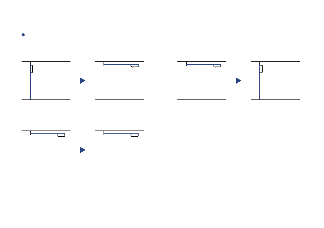
Device Alerts
Upon the opening or closing or le open for a set me of the garage door, an alert will be
sent to your YoLink account
Door is closed
Door is opened
Door is sll open for a set me
26
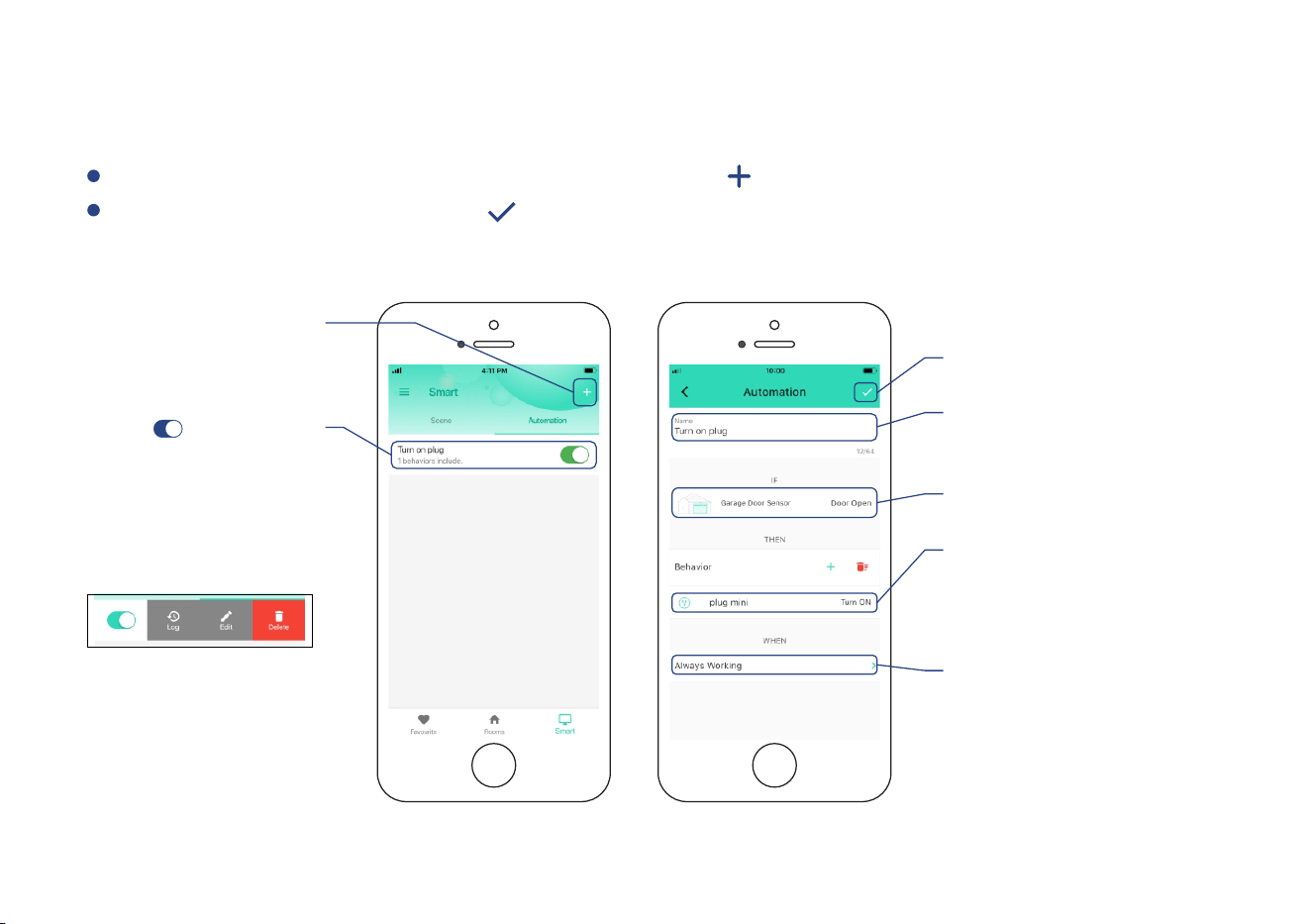
Automaon
Easily set up rules for “if this then do that” funcons
Go to “Smart”, tap “Automaon” followed by the “ ” icon to add an automaon
Fill in details followed by the “ ” icon
Tap to add an
automaon
Tap “ ” buon
to enable or disable
the automaon
* Click to edit the automaon.
Swipe le to view the history
logs and to edit or delete the
automaon
Edit trigger
Edit behavior
* You must have at least one
acon device, or you cannot set
a behavior
Edit when
* Set a me range for the
automaon (always or during
specific days / mes)
Edit name
for the automaon
Tap to save the sengs
* Garage Door Sensor 2 can be set as a trigger only, Garage Door Controller cannot be set as either a trigger or an acon device
27
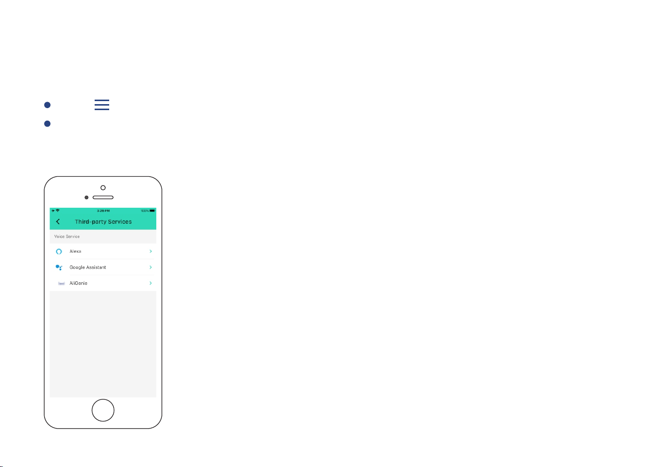
Voice Assistants
Go to Sengs > Voice Assistants for the applicable voice assistant integraon guide
Tap “ ” in the upper le corner to go to My Profile
Connect YoLink with third-party voice assistants service to monitor the status of your devices
through voice commands
* Garage Door Kit 3 is integrated with Alexa and Google Assistant only when the Garage Door Controller is paired with the Garage Door
Sensor 2, and is also integrated with IFTT T.com
28

About YoLink Control
YoLink Control is our unique device-to-device control technology. Using YoLink Control, YoLink
devices can be controlled without the Hub or an internet connecon. (Use of YoLink Control is
oponal; you can use the Automaon feature in the app OR use YoLink Control, but YoLink
Control offers the benefit of operaon without the Hub or internet connecon.)
One device controls another, directly. A device that sends out commands is called the controller. A
device that receives the commands is called the responder. Examples of a controller are a Door
Sensor or Water Leak Sensor, while examples of a responder are a Siren or a YoLink Plug Mini
To configure your Garage Door Sensor 2 as a controller, turn the sensor into opened status
(verify the door is opened). Press and hold the SET buon for 5-10 seconds unl the LED
quickly blinks green
Upon pairing, the LED will stop blinking (this may happen aer only blinking two or three mes)
To configure a as the responder n on the plug using YoLink Plug Mini . Tur POWER buon or
via YoLink app Mini (verify the Status LED of YoLink Plug displays blue). Press and hold the
POWER buon for 5-10 seconds unl the LED quickly blinks blue
Pairing
The Garage Door Sensor 2 can only work as the controller of YoLink Control, while the Garage Door
Controller does NOT support YoLink Control
29

Note
If you want to turn off the YoLink Plug when the door is opened, turn off the YoLink Mini
Plug first, and let it enter pairing mode Mini
For the same Garage Door Sensor 2 and YoLink Plug , you can only choose to either turn Mini
on or turn off the YoLink Plug when the door is opened Mini
If you want to turn on or off the Mini when the door is closed, YoLink Plug turn the sensor
into closed status (verify the door is closed), and let the closed door sensor enter pairing
mode
Also for the same Garage Door Sensor 2 and YoLink Plug , you can only choose to either Mini
turn on or turn off the YoLink Plug when the door is closed Mini
30
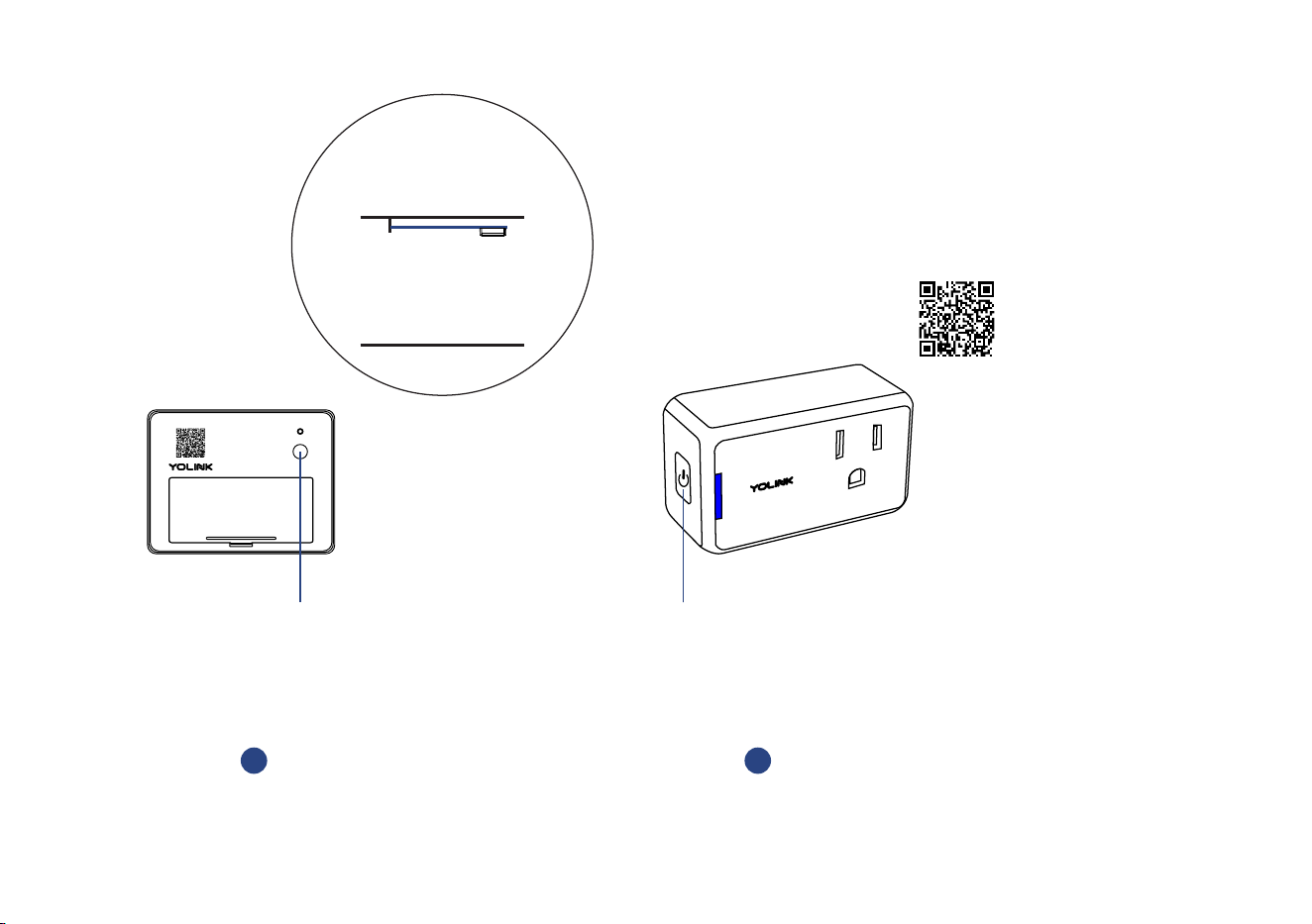
2
Hold the POWER button on the YoLink
Plug Mini (Turned on) for 5-10 seconds,
until the blue light blinks quickly
POWER Buon
Turn on the plug
* verify the Status LED of YoLink Plug
Mini Refer to the YoLink displays blue.
Plug Mini manual for more informaon:
YS6604-UC_YoLink Plug Mini
* Open the door first or just
keep the front side of sensor
downward
Hold the SET button for 5-10
seconds, until the green light
blinks quickly
1
SET
SET Buon
31
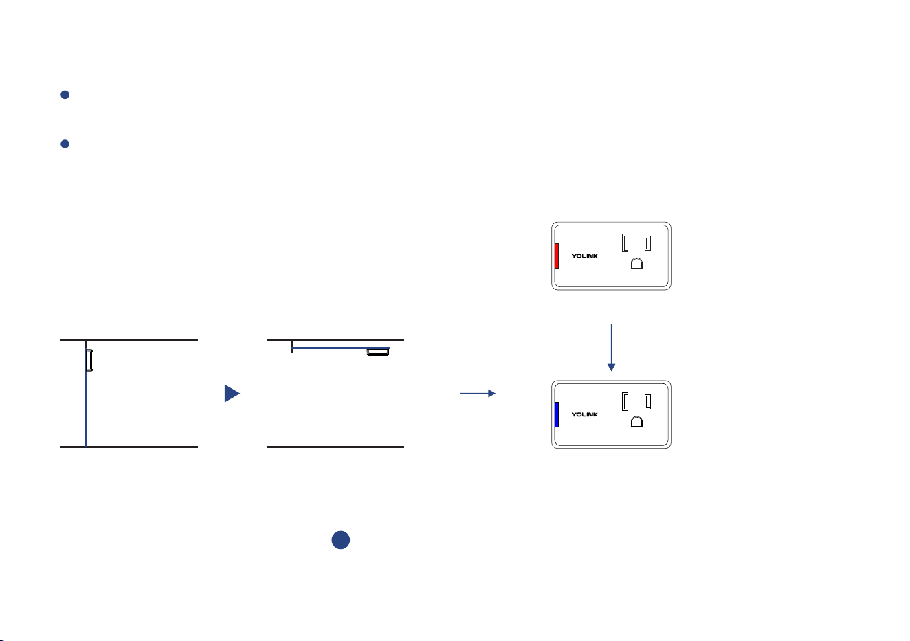
When the door is opened, the YoLink Plug Mini will be immediately turned on. The plug will
remain turned on unl turned off using the POWER buon or via the app
More advanced sequences, controlling mulple outputs (e.g. turn off plug and acvate siren)
are available via the YoLink app
Operaon
When the door is opened, the
YoLink Plug Mini will turn on
3
Door is opened
Turned on
Turned off
32

Unpairing
At t h e G a r a g e D o o r S e n s o r 2 ( c o n t r o l l e r ) , t u r n t h e s e n s o r i n to o p e n e d s ta t u s ( v e r i f y
t h e d o o r i s o p e n e d ) , p re s s a n d h o l d t h e S E T b u o n f o r 1 0 -1 5 s e c o n d s u n l t h e L E D
q u i c k l y b l i n k s g re e n, t h e n re d
Upon un-pairing, the Garage Door Sensor 2 LED will stop blinking and turn off, and the YoLink Plug
Mini LED will stop blinking and return to the previous color (blue for turned on, red for turned off)
At the YoLink Plug Mini (responder), press and hold the POWER buon for 10-15 seconds,
unl the LED quickly blinks blue, then red
The YoLink Plug Mini will no longer respond when the door is opened
Note
If you want to unpair the Garage Door Sensor 2 (closed status) with the YoLink Plug , turn Mini
the sensor into closed status (verify the door is closed), and let it enter unpairing mode
33
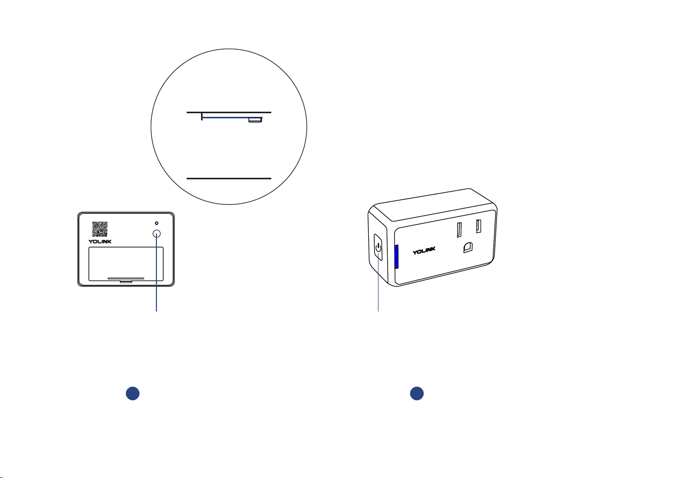
2
Hold the POWER button on the YoLink
Plug Mini for 10-15 seconds, until the red
light blinks quickly
POWER Buon
* Plug is either turned on
or turned off
Hold the SET button for 10-15
seconds, until the red light
blinks quickly
1
* Open the door first or just
keep the front side of sensor
downward
SET
SET Buon
34
Maintenance
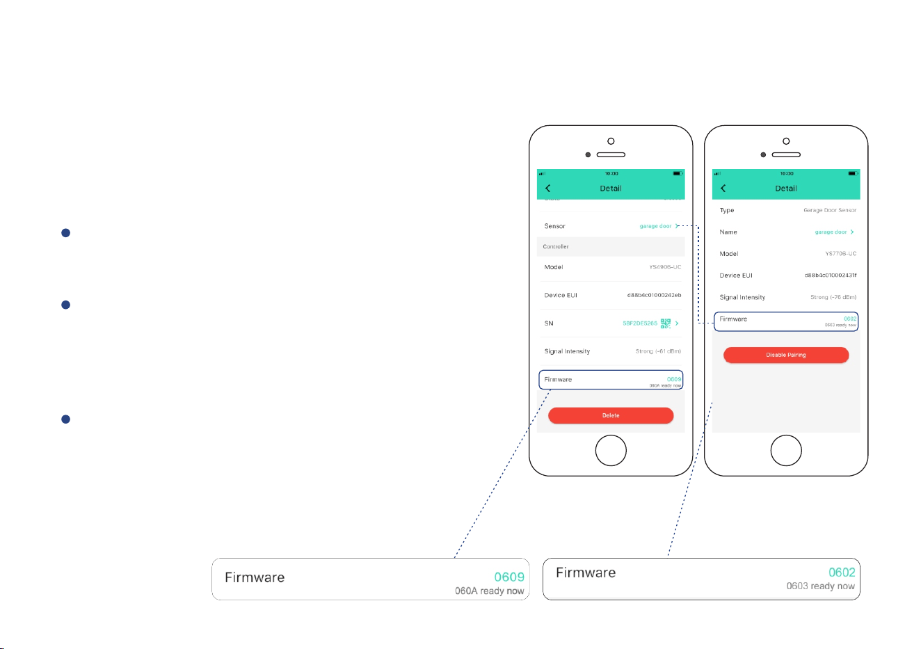
Firmware Update (Pair with a Sensor)
To ensure our customers have the best user
experience, we highly recommend you update
to the newest version firmware when an update
is available
You may update the firmware of the sensor
following the same procedure. For the sensor, the
device's firmware will be updated automacally
within 4 hours (maximum). To force an immediate
update, press the SET buon on the device once to
make the device enter update mode
In “Firmware” , if a new version is listed as
available (#### ready now), click it to start the
firmware update process
You may use your device during the update as it
is performed in the background. The LED light
will slowly blink green during the update and
the process will be complete within 2 minutes
aer the light stops blinking
35
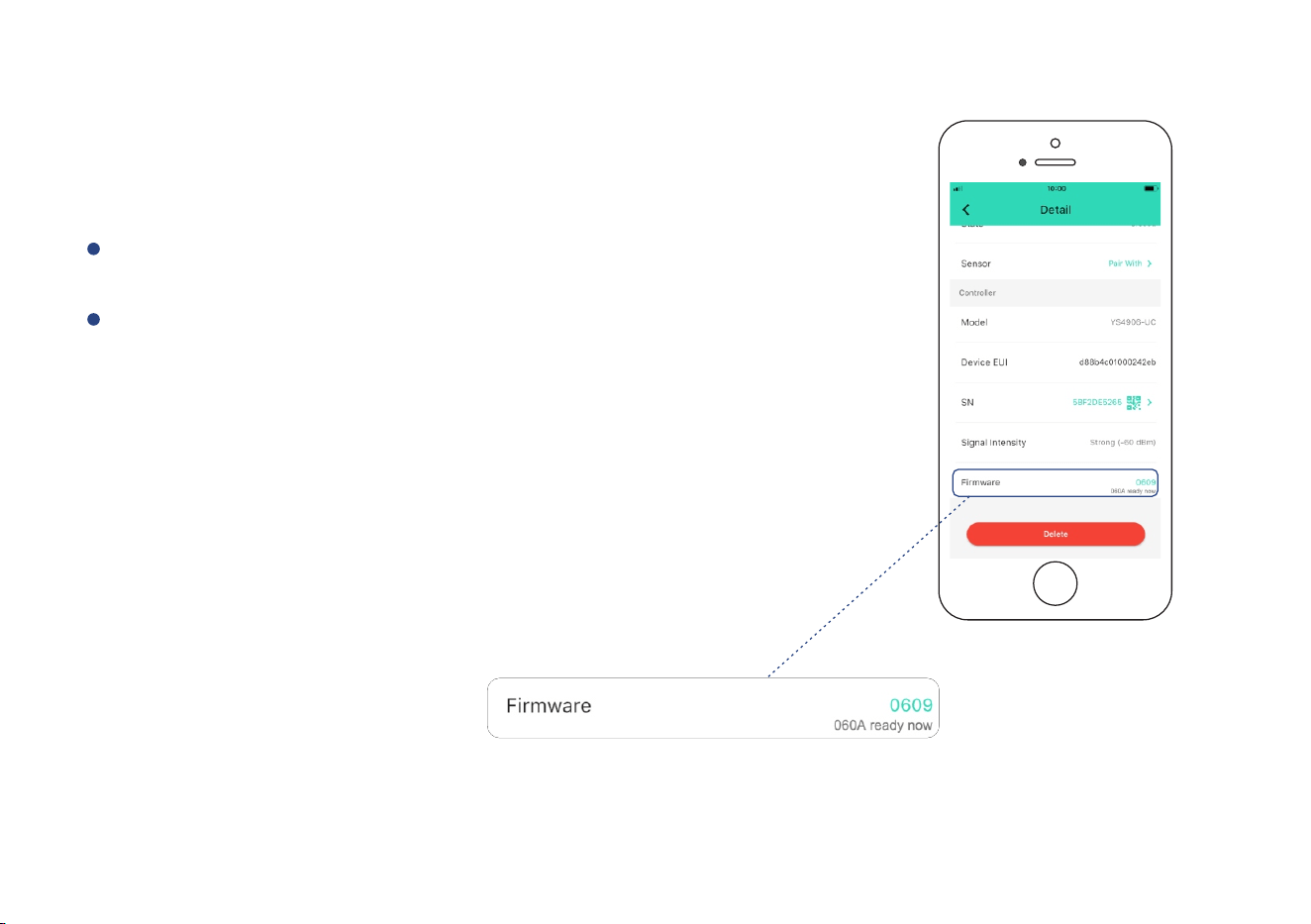
Firmware Update (Controller Only)
To ensure our customers have the best user experience,
we highly recommend you update to the newest version
firmware when an update is available
In “Firmware”, if a new version is listed as available (####
ready now), click it to start the firmware update process
You may use your device during the update as it is
performed in the background. The LED light will slowly
blink green during the update and the process will be
complete within 2 minutes aer the light stops blinking
36
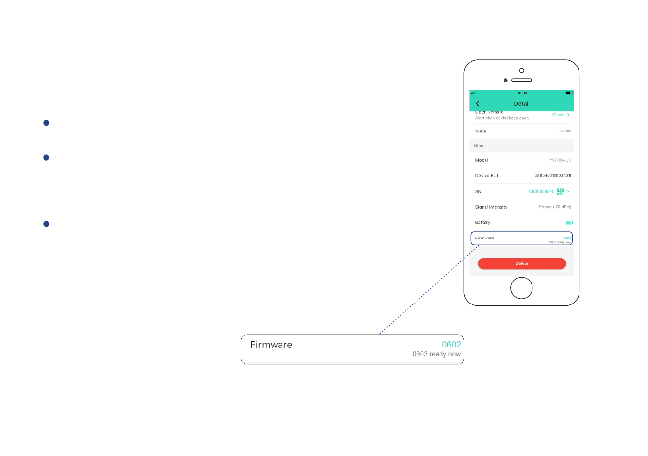
Firmware Update (Sensor Only)
To ensure our customers have the best user experience,
we highly recommend you update to the newest version
firmware when an update is available
In “Firmware”, if a new version is listed as available (####
ready now), click it to start the firmware update process
The device's firmware will be updated automacally within
4 hours (maximum). To force an immediate update, press
the SET buon on the device once to make the device enter
update mode
You may use your device during the update as it is
performed in the background. The LED light will slowly
blink green during the update and the process will be
complete within 2 minutes aer the light stops blinking
37
Factory Reset
Factory reset will erase all of your sengs and restore it to factory defaults. Aer the factory reset,
your device will remain in your Yolink account
38
Factory reset will be complete when the status light stops blinking
You may factory reset the sensor following the same procedure
SET Buon
SE T
SET Buon
Hold the SET buon for 20-25 seconds unl the status light blinks red and green alternately,
then, release the buon (Hold the SET buon longer than 25 seconds will ABORT the factory
reset operaon)
39
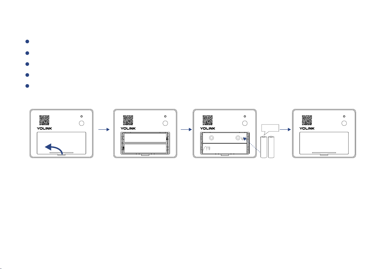
Replacing the Baeries (Garage Door Sensor 2)
Remove the baery cover by gently prying with your fingerp or tool at the edge as shown
Remove the old baeries
Install new , and then close the baery covertwo AAA baeriesalkaline non-rechargeable
Using the app, check the online status of the sensor and verify there is no low-baery indicator
Note: do not mix old and new baeries
Remove the baery cover
SE T
Remove the old baeries
SE T
Install two new AAA baeries
2 x AAA
SE T
Close the baery cover
SE T
Specificaons
Current:
1A
Voltage:
3V DC (2 - AAA baery)
Garage Door Sensor 2
Voltage:
5V DC
Garage Door Controller
Dimensions:
2.09 x 1.93 x 0.98 inch (L x W x D)
Environment:
Working Temperature: 32°F - 104°F (0°C - 40°C)
Working Humidity: 10% - 90% non-condensing
Environment:
Working Temperature: 32°F - 104°F (0°C - 40°C)
Working Humidity: 10% - 90% non-condensing
Dimensions:
2.56 x 1.97 x 0.69 inch (L x W x D)
40

Hardware:
Garage Door Controller cannot compable for all the garage door openers, visit 1. Wiring:
yolink.net to check compability of your garage door opener first
2. Input voltage: Be sure device is powered by 5V AC
Symptom:
1. Device is offline
- If controller is not connected to the cloud, press the SET buon on controller once
- If Hub is offline, reconnect the Hub to the Internet and press the SET buon on controller once
- If Hub is not on, power on the Hub again and press the SET buon on controller once
- If controller is out of range with Hub, relocang the Hub may be required
- If controller is not turned on. Turn on the device
2. Other issues, contact customer service, 1-949-825-5958 (M-F 9am - 5pm PST)
Garage Door Controller Troubleshoong
41

Hardware:
Baeries: Baeries should be brand new, name brand “AAA” alkaline type. Refer to “Warnings”
Secon on page 41
Symptom:
1. Device is offline or no alert received from door opened/closed events
- If senor is not connected to the cloud, press the SET buon on senor once
- If Hub is offline, reconnect the Hub to the Internet and press the SET buon on senor once
- If Hub is not on, power on the Hub again and press the SET buon on senor once
- If senor is out of range with Hub, relocang the senor or Hub may be required
- For a device with low-baery indicators or alerts or if the condion of the baeries is in
queson, replace the baeries with 2 premium “AAA” alkaline baeries
2. Other issues, contact customer service, 1-949-825-5958 (M-F 9am - 5pm PST)
Garage Door Sensor 2 Troubleshoong
42

Warning
Please install, operate and maintain the Garage Door Controller and Sensor 2 only as directed
herein. Failure to follow the informaon in this manual can void the warranty and result in
malfuncons and/or equipment failure
Garage Door Controller and Sensor 2 are not waterproof and are designed and intended only for
indoor use. Subjecng s to outdoor environment condions such as direct these two device
sunlight, extreme hot or cold temperatures, rain, water and/or condensaon can damage the
device and will void the warranty. Refer to Specificaons (page ) for the device environmental 38
limitaons
If your Garage Door Controller or Sensor 2 gets dirty, please clean it by wiping it down with a clean,
dry cloth. Do not use strong chemicals or detergents, which may discolor or damage the exterior
and/or damage the electronics, voiding the warranty
Do not install or use this device where it will be subjected to physical impacts and/or strong
vibraon. Physical damage is not covered by the warranty
Power the controller with the included power adapter and USB cord, only. Powering the controller
with other power supplies and voltages can result in severe damage to the controller, which is not
covered by the warranty
Power the sensor only with two AAA baeries (see below, regarding baeries)
Use only new, name brand, alkaline non-rechargeable AAA baeries
Do not use rechargeable baeries
Do not use zinc blend baeries
43

Do not puncture or damage baeries. Leakage can cause harm on skin contact, and is toxic if
ingested
Do not dispose of baeries in fire as they may explode! Please follow local baery disposal
procedures
To avoid damaging the device, if storing the device for an extended period, remove the
baeries
Please contact Customer Service before aempng to repair, disassemble or modify the
device, any of which can void the warranty and permanently damage the device
Do not mix new and old baeries
44

If you have any difficules installing or using your Garage Door Kit 3, please
contact our Customer Service department during business hours:
US Live Tech Support: 1-949-825-5958 M-F 9am - 5pm PST
Email: service@yosmart.com
YoSmart Inc. 17165 Von Karman Avenue, Suite 105, Irvine, CA 92614
Warranty 2 Year Limited Electrical Warranty
YoSmart warrants to the original residenal user of this product that it will be free from defects in
materials and workmanship, under normal use, for 2 years from the date of purchase. User must
provide a copy of original purchase receipt. This warranty does not cover abuse or misused products
or products used in commercial applicaons. This warranty does not apply to Garage Door Kit 3that
have been improperly installed, modified, put to a use other than designed, or subjected to acts of God
(such as floods, lightning, earthquakes, etc.). This warranty is limited to repair or replacement of the
Garage Door Kit 3 only at YoSmart's sole discreon. YoSmart will NOT be liable for the cost of installing,
removing, nor reinstalling this product, nor direct, indirect, or consequenal damages to persons or
property resulng from the use of this product. This warranty only covers the cost of replacement parts
or replacement units, it does not cover shipping & handling fees
To implement this warranty please give us a call during business hours at 1-949-825-5958, or visit
www.yosmart.com
Copyright 2020. YoSmart, Inc. All rights reserved
45

FCC Statement
This equipment has been tested and found to comply with the limits for a Class B digital device,
pursuant to part 15 of the FCC Rules. These limits are designed to provide reasonable protecon
against harmful interference in a residenal installaon. This equipment generates, uses and can
radiate radio frequency energy and, if not installed and used in accordance with the instrucons,
may cause harmful interference to radio communicaons. However, there is no guarantee that
interference will not occur in a parcular installaon. If this equipment does cause harmful
interference to radio or television recepon, which can be determined by turning the equipment
off and on, the user is encouraged to try to correct the interference by one or more of the following
measures:
Reorient or relocate the receiving antenna
Connect the equipment into an outlet on a circuit different from that to which the receiver is
connected
Increase the separaon between the equipment and receiver
Consult the dealer or an experienced radio / TV technician for help
This device complies with part 15 of the FCC Rules. Operaon is subject to the following two
condions:
1) This device may not cause harmful interference
2) This device must accept any interference received, including interference that may cause
undesired operaon. Any changes or modificaons not expressly approved by the party
responsible for compliance could void the user’s authority to operate the equipment

This equipment complies with FCC RF radiaon exposure limits set forth for an uncontrolled
environment. This device and its antenna must not be co-located or operang in conjuncon with
any other antenna or transmier.
“To comply with FCC RF exposure compliance requirements, this grant is applicable to only Mobile
Configuraons. The antennas used for this transmier must be installed to provide a separaon
distance of at least 20 cm from all persons and must not be co-located or operang in conjuncon
with any other antenna or transmier.”
FCC RF Radiaon Exposure Statement
Note: The manufacturer is not responsible for any radio or TV interference caused by unauthorized
modificaons to this equipment. Such modificaons could void the user’s authority to operate the
equipment.