32
AUTHORISED DEALER
In compliance with art.13 of the Legislative Decree n. 151 dated 25 July 2005,
”Implementation of the 2002/95/CE,2002/96/CE and 2003/108/CE
Directives, relative to the reduction of the use of dangerous substances in
electric and electronic appliances, as well as the disposal of waste”
The barred wheeley-bin symbol on the appliance or the package indicates that
at the end of the products useful life span, it must be collected separately from
other waste. The recycling of this product at the end of its service life, is ar-
ranged for and carried out by the manufacturer. The user who wishes to dis-
pose of this product must therefore contact the manufacturer and adhere to the sys-
tem that he has adopted for the correct disposal of this product at the end of its ser-
vice life. The correct disposal of the old product for the processes of recycling, treat-
ment and compatible waste disposal will help prevent potential negative conse-
quences for the environment and human health, and will result in the reuse and recy-
cling of the materials and components which make up the appliance.
Abusive disposal of the appliance leads to the application of administrative
sanctions envisioned by the Standards in force.
7.2 WEEE Waste Electric and Electronic Equipment
1
English
30
40
50
70
Ver. 001 Ed. 05.2020
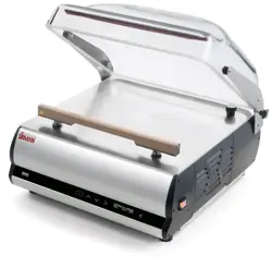
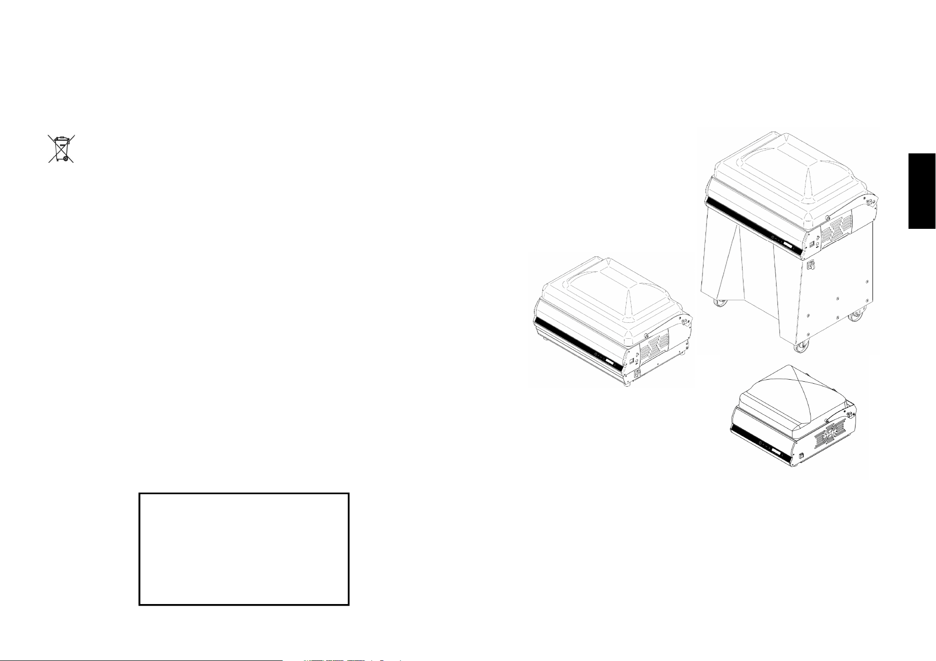
VACUUM PACKAGING MACHINE
USE AND MAINTENANCE MANUAL

2
31
English
6
Obligations in the event of malfunctioning and/or potential
dangers
The operators must inform their direct seniors of any deficiency and/or potential
dangerous situation that should occur.
6.1 - User obligations
The user must inform the manufacturer immediately if any defects and/or
malfunctioning of the accident-prevention system are detected, as well as any
presumed dangerous situation of which he becomes aware.
It is prohibited for the user and/or third parties (excluding duly authorised
manufacturer’s staff) to make any type or entity of modifications to the machine
and its functions, as well as to this technical document. In the event of
malfunctioning and/or dangers, owing to failure to respect the afore-said, the
manufacturer is not liable for any consequences. We recommend you request any
modifications from the Manufacturer.
7 Troubleshooting
7.1 - Troubleshooting
1 After having connected the master switch, the machine does not start:
a) Check that the plug is well inserted into the socket and, if necessary, control the
contacts inside the plug itself.
b) Check that on lowering the lid, the micro switch positioned on the rear below
the left fixing hinge, is excited.
2 The machine operates regularly, but the package is not sealed when the
lid is opened
a) Lift the Teflon and check that the resistance is not interrupted and it is blocked
on the lateral clamps.
3 If the machine does not achieve an excellent vacuum
a) Close the lid and disconnect the line when a negative pressure of about 90%
has been reached. Check whether the vacuum percentage indicated on the
display remains fixed or decreases.
- In the first case, there are no leaks, therefore the problem has another source
(pump vanes, oil replacement).
- In the second case, there is the presence of air infiltration into the lid:
• Check the membrane below the sealing bar, checking that it has no holes or
is ripped
• Check the integrity of the sealing gasket positioned under the lid; if the
afore-mentioned pieces must be replaced, request them directly from the
authorised dealer.

30
5 Controls and maintenance
5.1 - Controls and maintenance
Access to the internal part of the machine is reserved exclusively to our special-
ised technician.
If the machine is accessed voluntarily, the manufacturer declines all civil and penal
liability regarding any accidents or damage caused to persons or objects.
All electric components are protected within the machine body and the relative
guard must be removed in order to gain access. Whenever access must be made,
remove the plug from the electric control board current socket.
5.2- Maintenance
1. Clean the sealing bars and the silicon counter-bar more or less every 15 days
using alcohol.
2. Change the oil every 400 hours of working (data variable depending on the type
of product packed).
After 2000 cycles the machine envisions an automatic oil control, the display
shows the “oil change” message. The user must call the dealer, who will
check the efficiency of the oil and will replace it, if necessary.
3. Replacement of electric resistances, Teflon sealing bar, lid sealing gaskets
about every 200 working hours.
4. Replacement of the silicon counter-bar
5. Check pump vanes, filters, pneumatic solenoid valve seals every 35,000
work cycles.
5.2.1 - Vacuum pump
For the safeguarding and the duration of the vacuum pump, follow the indications
given below scrupulously:
- Do not suck up steam, liquids and flours of any type.
This compromises the viscosity of the pump oil and damages the pump itself.
- Periodically check the pump oil level through the visual inspection window
A level below minimum can damage the pump
A level above maximum can damage the pump filter and the pump itself
- Periodically check the colour of the pump oil. If the oil appears
cloudy, dark or emulsioned, it must be replaced immediately.
- Replace the pump oil every 2 / 4 / 6 or 12 months, depending on use and location
of the equipment, or appearing the notice "change oil" on the display.
The pump oil may have to be replaced every month.
-
Replace the pump oil before prolonged machine shutdown.
ATTENTION!!:
Considering that the vacuum packaging machine is nearly always located in the
kitchen, an environment full of steam and humidity, the level and quality of the
pump oil must be checked constantly and replaced frequently and periodically.
AGIP ARNICA 32 Q8 HAENDEL 32
SHELL TELLUST 32 ESSO INVAROL EP46
Types oil
3
English
INDEX
1. Delivery and warranty 5
1.1 Foreword.
1.2 Preservation and use of this manual
1.3 Warranty
1.4 General recommendations and limits of liability of the Manufacturer
1.5 Description of the machine
1.6 Declared use
1.7 Use not allowed
1.7.1 Safety prescriptions
1.7.2 Lighting
1.8 Company information
1.8.1 Warning and Danger signs
2. Technical features 9
2.1 Main parts
2.2 Technical features
2.3 Dimensions and weight of the machine
2.4 Wiring diagram
2.4.1 Wiring diagram
3. Inspection, transport, delivery and installation 13
3.1 Inspection
3.2 Delivery and handling of the machine
3.3 Installation
3.3.1 Disposal of packaging
3.4 Connections
3.5 Electrical system hook-up
3.5.1 3-phase machine (220 V/60 Hz)
3.5.2 Single phase machine (120 V/60 Hz)
4. Using the machine 15
4.1 Key to controls
4.2 First power-up, installation settings
4.2.1 MENU language setting
4.2.2 Use type setting
4.2.3 Vacuum sensor calibration
4.2.4 Oil heating
4.3 Secondary settings
4.3.1 Oil heating and cleaning
4.3.2 Inert gas setting (where provided)
4.3.3 Printer setting
4.3.4 Label counter
4.3.5 Label counter reset
4.3.6 Label setting
4.3.7 Date and time setting
4.3.8 Buzzer volume setting
4.3.9 Reset WiFi
4.3.10 Date and time setting
4
4.4 Vacuum packing
4.4.1 Automatic packaging
4.4.2 Packaging with inert gas injection (optional)
4.4.3 Packaging with the use of the thermal printer
4.5 Packaging of liquid or semi-liquid products
4.5.1 Packaging liquid or semi-liquid products with the aid of the standard
inclined surface
4.5.2 Packaging thin products with the aid of the optional raised surface
4.5.3 Packaging of products in external trays (with vacuum % control)
4.5.4 Packaging of products in external trays (with vacuum time control)
4.6 Examples of packaging in controlled atmosphere
4.7 Cleaning the machine
4.8 Machine at rest
4.9 Vacuum pump heating
4.10 Alarms
5. Controls and maintenance 30
5.1 Controls and maintenance
5.2 Maintenance
5.2.1 Vacuum pump
6. Obligations in case of malfunctioning and/or potential dangers 31
6.1 User obligations
7. Troubleshooting 31
7.1 Troubleshooting
7.2 WEEE Waste Electric and Electronic Equipment
29
English
The equipments makes 2 sounds ath the end
of the process, the display will show 13 LED’s
on and a temperature of 70°.
Then the message READY TO USE, THANK YOU will show.
The equipment will return automatically to the
program in use before the alarm.
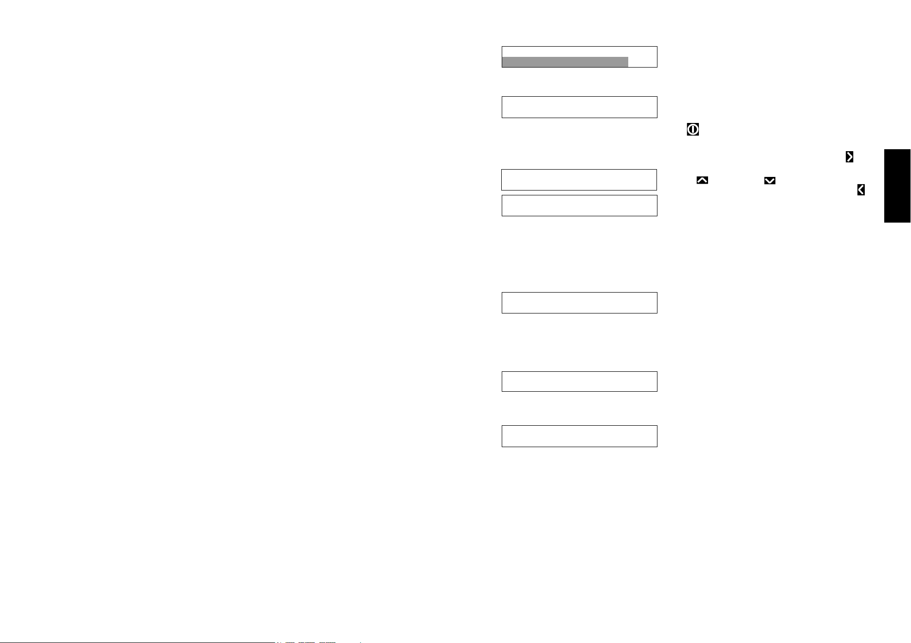
The oil heating cycle can be stopped by pressing ON and will be considered
not
completed.
The oil cleaning cycle can be po-
stponed as the message
shows. Press RIGHT arrow to change, Im-
mediately starts flashing.
Use UP and DOWN arrows to select Postpone,wait for 5 seconds Or press LEFT
arrow to confirm, the selected command will stop flashing.
A new message will remind to clean oil after 50 cycles.
OIL MIX
If the equipment is seldom in use, this automatic procedure will keep the pump
efficient and well lubricated.
The display shows AUTO OIL MIX, the mes-
sage DO NOT STOP will flash during a 15
seconds countdown, no action is requested during this process. The equipment
will then return to standby mode.
If the equipment is seldom in use,switched off and disconntected from the power
source, the automatic procedure that lubrica-
tes the pump is blocked. After the equipment
is switched on, the display may show the mes-
sage POSSIBLE PUMP STUCK, which is not a proper alarm but rather a chance
to be verified. Once the warning is over, the equipment can operate as usual, if the
pump is working regularly, the warning is auto-
matically reset.
If the pump is actually stuck, the display will
show the message STUCK PUMP, the electronic control will stop the pump in or-
der to avoid any damage. Refer to the technical service to proceed with the main-
tenance of the pump at this point.
O I L
P o s
H E
t p o
A T I N G
n e
C Y C L
O I L
H E
A T I N G
C Y C L
7 0 °
R E
A D Y
T h a
T O U S
n k y o u
E
!
A U T
D o
O O
n o t
I L M I X
s t o p !
1 5
O I L
I m m
H E
e d i
A T I N G
a t e l y
C Y C L
P O S
S T U
S I B
C K
L E P U M
P
P U M
C a l
P I
l s
S S T U C
e r v i c e
K

28
4.10 Alarms
OIL REPLACEMENT
The message “REPLACE OIL” appears on
the display when the equipments reaches the
maximum amount of cycles.
The equipment stops working and the message shows for 10 seconds, as a
warning for the operator, then the displays returns to the program that was in use.
The equipment can be used further until it reaches 200 cycles, then it stops again
and shows the message REPLACE OIL for 30 seconds, then it starts again.
EQUIPMENTS WITH AUTOMATIC OIL REPLACEMET (A.O.R.)
If the equipment has the A.O.R. installed, it stops and shows the message
“AUTOMATIC OIL REPLACEMENT”.
Use RIGHT and LEFT arrows to select YES
or NOW, the selected values will flash. Wait
for 5 seconds until the next step.
If NO is selected, the equipement will start
again and will work further for 50 cycles. After
50 cycles the oil replacement message will
appear again and YES will be the only option
to be selected.
Select YES
Follow the instructions on the display.
The display shows: CONNECT OIL TANK
AND PRESS “ON”, after ON is
pressed the display will show OIL
REPLACEMENT RUNNING.
At the end of the procedure the equipment will
make a sound.
If the display shows REPLACE OIL TANKS it means the oil tank is full, and
reminds the operator to replace the tanks
during the next oil replacement.
The equipment is now ready.
PUMP OVERHEATING
When the temperature sensor reaches 90°, the equipment stops until the
temperature returns to 70°. The display shows PUMP TEMP. 90° STARTS AGAIN
AT 70°
This message keeps showing until the
temperature reaches 70°.
The equipments starts automatically after the pump has cooled down.
C H A
O I L
N G E
P U M P
6 0
O I L
A U T
R E
O M A
P L A C E M
T I C Y E
E N T
S - N O
O I L
A U T
R E
O M A
P L A C E M
T I C
E N T
Y E S
C O N
A N D
N E C
P R
T O I L
E S S O N
T A N K
O I L
O N G
R E
O I N
P L A C E M
G
E N T
R E P
T A N
L A C
K
E O I L
P U M
R e s
P T
t a r
E M P .
t s a t
9 0 °
7 0 °
O I L
I m m
H E
e d i
A T I N G
a t e l y
C Y C L
O I L
C l o
H E
s e
A T I N G
b l a c k
C Y C L
c a p
5
English
1 Delivery and warranty
1.1 - Foreword
ATTENTION!
The symbols used in this manual intend to call the reader’s attention to points and
operations that put the operator’s personal safety at risk or which can cause
damage to the machine itself.
Do not operate with the machine if you are not certain to have correctly understood
that highlighted in these notes.
ATTENTION!
Some illustrations in this manual represent the machine or parts of the same with
panels or guards removed. This is in order to make things clearer.
Do not use the machine in these conditions, but only with all protections mounted
correctly and in perfect working order.
The Manufacturer prohibits reproduction, even partial, of this manual and its
content cannot be used for purposes not permitted by the same.
Any breach thereof will be dealt with under the provisions of said Law.
1.2 - Preservation and use of the manual
The purpose of this manual is to make the users of the machine aware of the
prescriptions and essential criteria relative to transport, handling, use and
maintenance of the machine itself, via texts and figures.
Therefore, this manual must be read thoroughly before the machine is used.
Keep it in a safe place near to the machine, which is easy and quick to access for
future consultation.
If the manual is lost or deteriorated, request a copy from your dealer or the
Manufacturer directly.
If the machine is transferred, inform the Manufacturer of the name and address of
the new owner.
This manual reflects the state of the art at the time of marketing and cannot be
considered inadequate merely because it is updated successively on the basis of
new developments. The manufacturer also reserves the right to update production
and relative manuals without the obligation to updating earlier issues, except in
exceptional cases.
If in doubt, consult the nearest after-sales centre or the Manufacturer directly.
The manufacturer is intent on continuous optimisation of its product.
For this reason it is pleased to receive any signals or proposals for improvement of
the machine and/or manual.
The machine has been delivered to the user with valid warranty conditions at the
time of purchase.
Contact your own supplier for all clarifications.

6
1.3 - Warranty
The Manufacturer is committed for 12 (twelve) months, from the date of shipping
and direct delivery of the goods, to guaranteeing the customer or authorised dealer
the integrity and good operation of the components relative to the machinery in
question.
The warranty excludes all parts of the machinery subject to normal wear, i.e
components in which use generates unstoppable constant wear:
A. Electric resistances – Teflon - Sealing gaskets – Lid opening pistons – Sealing
membrane– Air filters – Oil filters – Oil change – Pump vanes.
B. Whenever a vacuum pump relative to a machine under warranty is returned to
the Manufacturer due to problems regarding suction and malfunctioning, the
Manufacturer reserves the right to control whether foreign bodies have been
sucked up: (liquids, solids, juices, sauces etc.). If this situation is verified, the
repair materials and labour will be charged regularly, as the problem is not
linked to manufacturing defects but Customer negligence during use.
C. Any problems linked to the electronic circuit boards of the circuit must be
examined by the Manufacturer before the piece to be replaced is sent under
warranty. A voltage change, electric over-feeding, interference in the external
mains, could cause damage that is not the manufacturer’s fault or which can
be blamed on the manufacture of the piece.
D. Any problems linked to pneumatic, structural, mechanical parts, will be solved
normally under warranty without charge.
E. During the warranty period, for interventions covered by the same, there will
be no charge for the materials replaced, while labour costs will be calculated.
For any interventions performed during the warranty period that are not
covered by the warranty itself, the materials replaced and the labour will be
charged regularly.
F. If external interventions by our technicians are requested during the warranty
period, travel expenses (return) will be charged in full, independent of the
cause of the intervention.
1.4 - General recommendations and limits of liability of the
Manufacturer
Every operator-machine interaction, within the declared use ambit and the entire
life cycle of the same, has been carefully and thoroughly analysed by the
Manufacturer during the design and construction phases and when drawing up the
instruction manual. In spite of this, it is intended that nothing can replace the
experience, suitable training and especially the “good common sense” of those
interacting with the machine. The last requisites are therefore deemed
indispensible in every operational phase inherent the machine and when reading
this manual.
Failure to comply with the precautions or specific recommendations present in this
manual, use of the machine by unsuitable staff, violate all Safety Standards
concerning the design, manufacture and declared use of the supply and relieve the
Manufacturer from all liability in the event of damage/injury to objects/persons.
27
English
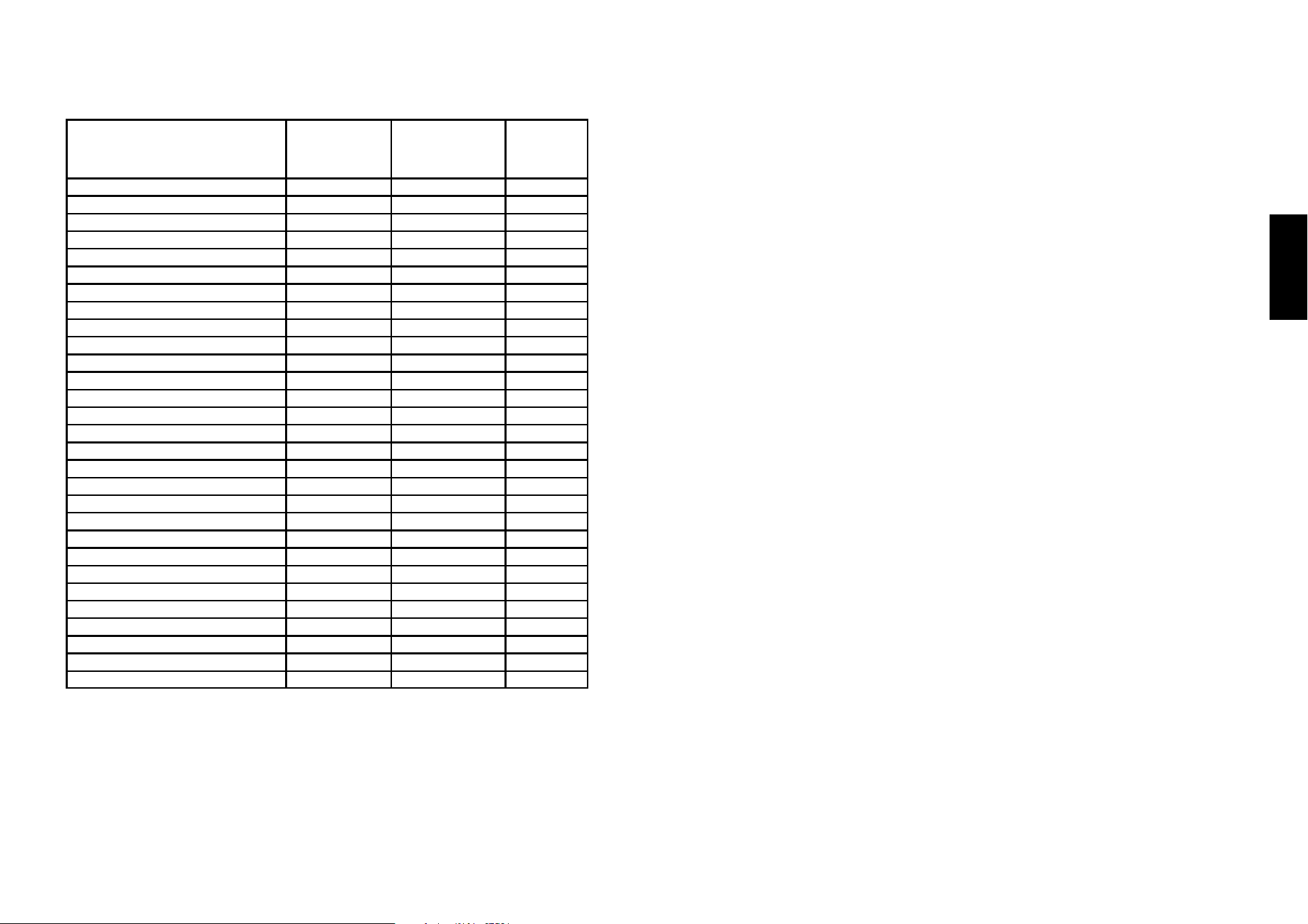
The table below shows some product types with the
mixtures that have been established for them.
"To guarantee the machine inlet pressure of 0.4 – 0.5 Bar, we recommend
using a pressure gauge with a scale from 0 to 3 Bar to set the gas pressure
because it is much more accurate than one with a scale from 0 to 30 Bar.
The machine could have problems during operation if the gas inlet pressure
is not as specified.
"
4.7 - Cleaning the machine
ATTENTION!
Disconnect the machine from the mains electricity before cleaning.
Do not clean the machine using a jet of water. Use non-toxic detergents only,
expressly intended for clearing components coming into contact with foodstuffs.
DO NOT use chlorine-based detergents. DO NOT use ethyl alcohol to clean the
lid. The lid must be cleaned regularly with a soft, damp cloth, using cold or warm
water, with a small amount of neutral detergent. It is recommended to avoid:
- the use of products containing: denatured ethyl alcohol, solvents in general,
Benzene, Trichloroethylene
- the use of abrasive materials and contact with sharp objects
Drying When the lid has been cleaned, it can be dried using a slightly damp
chamois cloth, without rubbing hard.
4.8 - Machine at rest
ATTENTION! If the machine is not used for a long period of time, to prevent dirt
and dust depositing inside the chamber, close and fix the lid using the relevant
fixing knob. If the machine is not to be used for a week or more , we suggest to
change the oil, even if this operation was done recently.
4.9 - Vacuum pump heating
During the winter period, in the morning it is recommended to briefly pre-heat the
FRESH MEATS
BEEF 30/40 days
VEAL 30/40 days
PORK 20/25 days
WHITE MEATS 20/25 days
RABBIT AND GAME ON THE BONE 20 days
LAMB/GOAT 30 days
SAUSAGES 30 days
OFFAL 10/12 days
26
PRODUCT OXYGEN %
(O
2
)
CARBON
DIOXIDE %
(CO
2
)
NITRO-
GEN %
(N
2
)
Deli cold cuts - 20 80
Bear/Beverages in cans - 100
Biscuits and baked products - 100 100
Coffee - 100 100
Freeze-dried meats and spices - - 100
Minced meat - - 100
Chocolate - 100 -
Fresh cheese/Mozzarella -/- 20/- 80/100
Hard cheeses - - 100
Fresh salad/Parsley - 50 50
Yogurt/Puff pastry - 100 -
Powdered milk - 30 70
Powdered dry yeast - 100 100
Apples 2 1 97
Sliced pork belly - 35 65
Sliced bread/Bread - 100 -
Toast/Danish toasts - 80 20
Pasta - - 100
Fresh pasta/tortellini/lasagne - 70/100 30
Potatoes/Chips/Snacks/Hops - 100
Blue Fish - 60 40
Pizza - 30 70
Poultry - 75 25
Tomatoes 4 4 92
Pre-cooked products - 80 20
Cured meats - 20 80
Fruit juices - - 100
Trouts/ Farmed fish - 100 -
Wine/Oil - - 100
4.6 - Examples of packaging in controlled atmosphere
NEVER USE MIXTURES WITH OXYGEN OVER 20%
PRESERVATION TIME OF VACUUM PACKE DPRODUCTS
KEPT AT A TEMPERATURE OF +0°/+3° C.
FISH: Average duration 7/8 days with extremely fresh product
CURED COLD CUTS: Maintenance time to perfection over 3 months
MATURED CHEESES: Grana, pecorino, etc. 120 days
FRESH CHEESES: Mozzarella, brie, etc 30/60 days
VEGETABLES: In general 15/20 days
7
English
The Manufacturer is not deemed liable for the consequences caused by the
user’s failure to comply with the safety precautions given in this manual.
1.5 - Description of the machine
The vacuum packaging machine with lid is controlled electrically and therefore not
subject to wear. The electronically-governed sealing system, is composed of a flat
resistance (5mm) stainless steel bar which, thanks to an excellent pneumatic
system installed, guarantees balanced and even sealing on any type of bag to be
used (nylon, polyethylene, Cryovac).
The vacuum pumps used are very modern and guarantee surprising silence even
though operating with uninterrupted cycles along with a very high level of final
vacuum.
The models represented in this manual have been created in compliance with the
2006/42 EEC Directive and successive amendments.
In the event of an accident, the manufacturer cannot be held responsible if the
machine has been modified, tampered with, the safety protections have been
removed or used in ways not declared by the manufacturer.
1.6 - Declared use
The machine has been designed and manufactured to vacuum pack products
according to the instructions in this manual and must be intended for this use only.
Any other use must be considered improper and therefore dangerous. The
Manufacturer cannot be considered responsible for any damage deriving from
improper, incorrect or unreasonable use.
It must be used in professional environments and any staff using the machine must
have experience in the sector and have read and understood this manual.
1.7– Uses not allowed
1.7.1 - Safety prescriptions
The following points must be respected:
1 never touch the metal parts of the machine with wet or damp hands;
2 do not pull the power supply cable or the appliance itself, to disconnect the plug
from the current;
3 do not allow the packaging machine to be used by children or untrained staff;.
4 the electric safety of this machine is only assured when the same is correctly
connected to an efficient earth plant, as envisioned by the electric Safety
Standards in force; this fundamental requirement must be verified. If in doubt,
request an accurate control of the system by professionally qualified staff; the
Manufacturer cannot be considered responsible for any damage caused by
the failure to earth the system;
5 in the event of possible damage to the earth protection, the machine must be put
out of service, in order to prevent undesired and/or involuntary activation;
6 always use protection fuses that are in compliance with the Safety Standards in
force, with the correct value and suitable mechanical features;
8
7 avoid the use of repaired fuses and the creation of short circuits between the
terminals on the fuse holders;
8 the packaging machine power supply cable must never be replaced by the user;
contact the machine manufacturer exclusively in the event of damage to the
cable, or for its replacement;
9 keep the cable away from hot parts;
10 always switch the machine off and disconnect it from the mains electricity
before starting any global clearing procedure or washing operation;
11 clean the machine coverings, panels and commands using soft, dry cloths
dampened in a weak solution of detergent or alcohol;
12 The machines for use with Gas are not set-up for use with mixtures containing
over 20% oxygen.
1.7.2 - Lighting
The place of installation of the machine must have sufficient natural and artificial
lighting in compliance with the Standards in force in the country of installation of
the packaging machine.
In all cases, the lighting must be uniform and guarantee good visibility in all parts
of the packaging machine and must not create dangerous reflections.
The lighting must allow the control panels to be read correctly and clearly identify
the emergency buttons.
1.8 - Company details
An exact description of the "Model", the "Serial number" and the "Year of
Manufacture" of the machine will facilitate quick and effective response by our after
-sales assistance. It is advised to indicate the model of the machine and the serial
number every time the after-sales service is contacted.
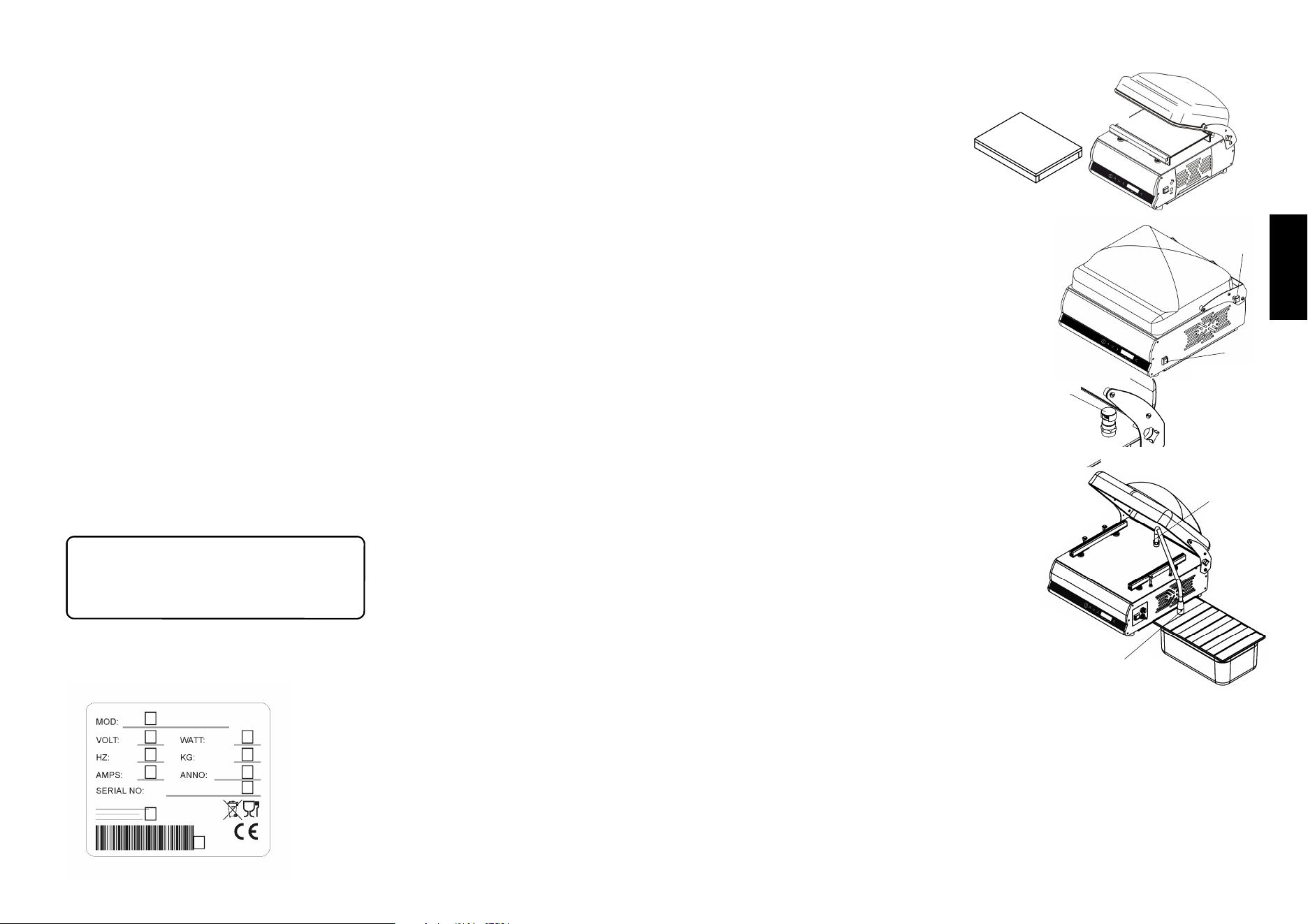
Identify the plate data represented in fig. 1.8.1.
We suggest you write the data of your machine in the box below as a
reminder.
Machine Model………………………..
Serial number……………………………………
Year of construction……………………………...
Type………………………………………………..
Fig. 1.8.1
E
A = Machine model
B = Power supply
C = Motor power
D = Motor frequency Hz
E = Weight
F = Amperage
G = Year of construction
H = Serial N°
I = Manufacturer
L = Bar code
A
B C
D E
F G
H
I
L
25
English
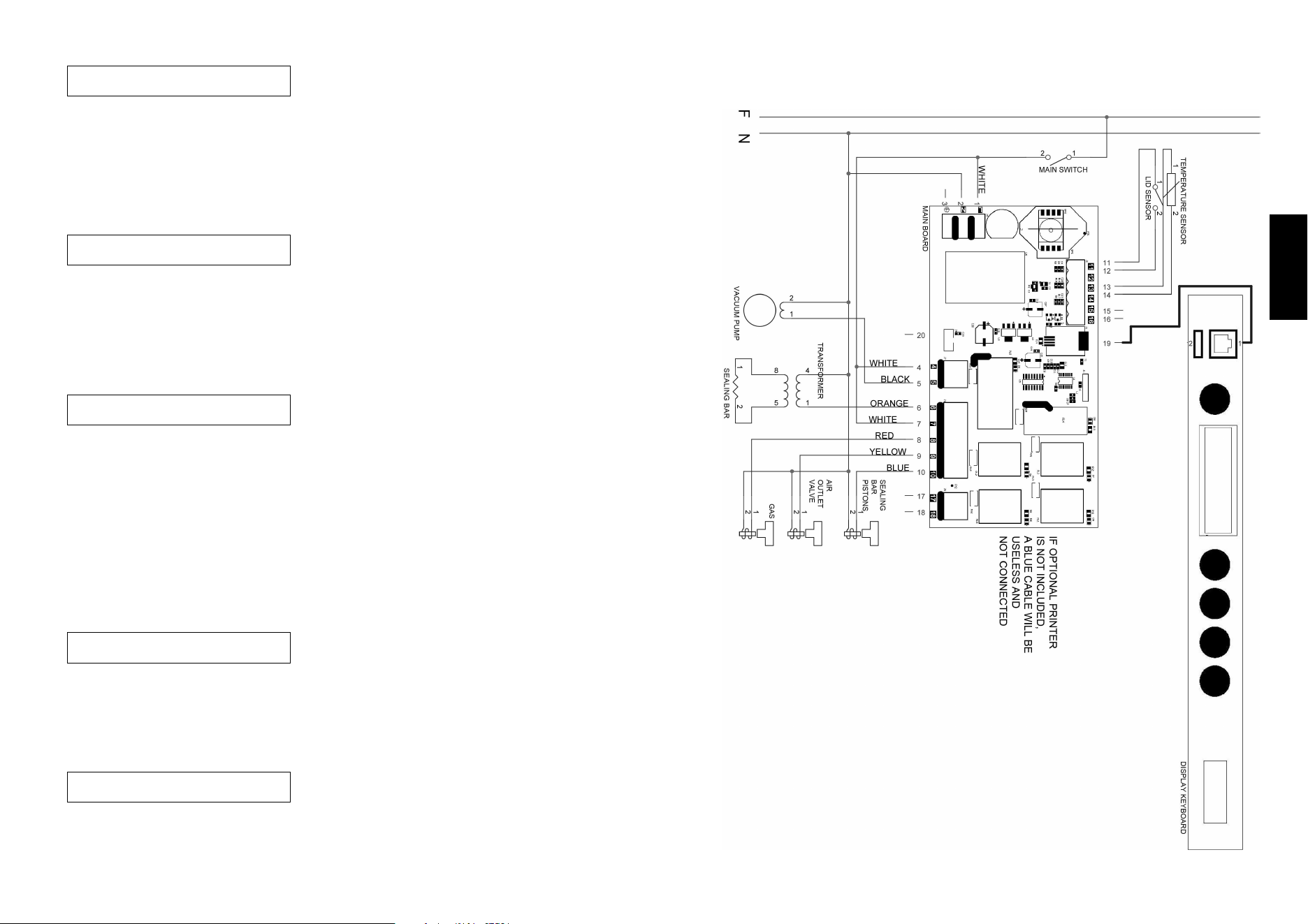
4.5.2 - Packaging thin products with the aid of the
optional raised surface
It is advisable to use the raised surface
to aid packaging of thin products such
as cold cuts.
Fig. 4.4.2
4.5.3 - Packaging products in external trays (with
vacuum % control)
It is advisable to use the external suction kit to aid
packaging of products stored in external trays.
1. Connect the machine to the mains power
2. Unscrew the black knob (ref. 1 in fig. 4.4.3) on the
right side of the machine to free the hood in order
to start operation.
3. Power up the machine with the switch (ref. 2 in
fig. 4.4.3) on the right side.
4. Select the “EXT VACUUM AUTO” program from
the menu.
5. Remove the suction cap (ref. 3 in fig. 4.4.4).
6. Attach the suction kit hose (ref. 4 in fig. 4.4.5).
7. Attach the suction kit connector to the tray cover valve
(ref. 5 in fig. 4.4.5).
8. Select the percentage vacuum that you want in the
tray (from 50% to 100%).
9. Use the start key to start the program.
10. The machine will stop automatically when the vacuum
reaches 100%
1
Fig. 4.4.3
2
Fig. 4.4.4
3
4.5.4 - Packaging products in external trays
(with vacuum time control)
1. Connect the machine to the mains power
2. Unscrew the black knob (ref. 1 in fig. 4.4.3) on the
right side of the machine to free the hood in order to start
operation.
3. Power up the machine with the switch (ref. 2 in fig. 4.4.3)
on the right side.
4. Select “EXT VACUUM TIME” from the program menu.
5. Remove the suction cap (ref. 3 in fig. 4.4.4).
6. Attach the suction kit hose (ref. 4 in fig. 4.4.5).
7. Attach the suction kit connector to the tray cover valve (ref. 5 in fig. 4.3.5).
8. Edit the suction time to the desired value.
10. Use the start key to start the program.
11. The machine stops automatically when the set suction time expires.
Fig. 4.4.5
4
5
24
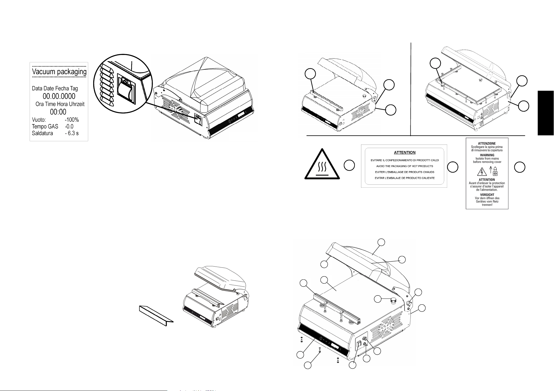
4.4.3 - Packaging with the use of a thermal printer
If the thermal printer option has been enabled in the machine, a label containing
the following data will be printed for each vacuum cycle:
Fig. 4.3.3
Pressing the left arrow once will print the last label again.
4.5 - Packaging liquid or semi-liquid products
Our hood vacuum packaging machine can be used to
vacuum pack liquid or semi-liquid products (soups, dressings, sauces, etc.) to
conserve them longer without altering their flavour or hygiene.
In such cases, the bags must never be filled to the limit, but only up to 50% of their
capacity, while ensuring that the edge is higher than the sealing bar.
1. Select the “LIQUID AUTOMATIC” program
2. Close the hood, and the process will start.
3. Since liquids are incompressible, there is no need for packaging in
a modified atmosphere, so inert gas is not required
4. The machine pauses twice before sealing the bag.
5. All packages can stored stacked normally in a cold store.
4.5.1 - Packaging liquid or semi-liquid products with
the aid of the standard inclined surface
It is advisable to use the inclined
surface to aid packaging of liquid
products.
Fig. 4.4.1
9
English
1.8.1 - Warning and danger plates (Fig. 1.8.2)
2 Technical features
2.1 - Main parts
To facilitate comprehension of the manual, the main machine components are
listed below and represented in fig. 2.1.1.
Fig. 2.1.1
1. Control panel
2. Surface
3. Power supply cable
4. Master switch
5. Transparent lid
6. Silicon counter-bar
7. Sealing gasket
8. Suction pipe for vacuum
9. Sealing bar
10. Lid fixing knob
11. Gas pipe fitting.
12. Soft-air cock
13. Front profile locking screws
A
B
C
Fig. 1.8.2
A
B
C
A
B
C
9
2
1
4
6
7
5
8
10
3
11
12
13
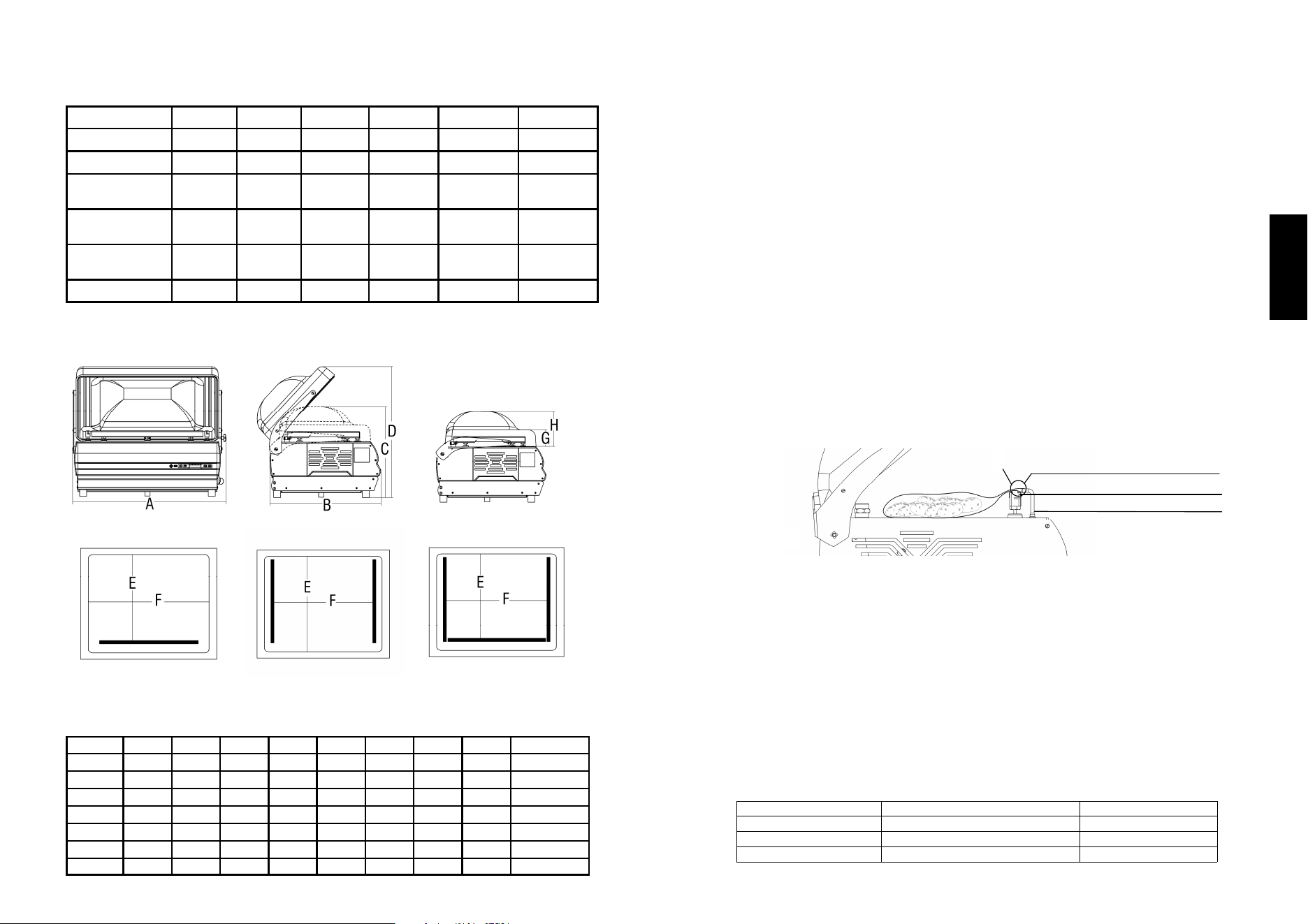
10
2.2 - Technical features
2.3 - Dimensions and weight of the machine
30/12 40 50
Power Kw 0,45 0,75 0,75
Vacuum pump 12 mc/h 21 mc/h 21 mc/h
Sealing bar 310 mm 410 mm 510 mm
Chamber
dimensions
340x360x
h130 mm
430x410x
h140 mm
540x430x
h190 mm
Power supply 120V/60Hz 120V/60Hz 120V/60Hz
Oil tank capacity ml 450 ml 450 ml 450
30/8
0,35
8 mc/h
310 mm
340x360x
h130 mm
120V/60Hz
ml 250
50 x2
0,75
21 mc/h
n. 2 x 410 mm
545x460x
h190 mm
120V/60Hz
ml 450
70/40
1.1 KW
40 mc/h
n. 1 x 640 mm
n. 2 x 410 mm
780 x 480
h 190 mm
220V 3ph/
60Hz
1 lt
A B C D Net weight
mm mm mm mm Kg
30
402 525 360 480 46
40
493 585 370 542 56
50
609 640 420 605 70
50 x2
609 640 420 605 71
E F G H
mm mm mm mm
333,5 340 85 140
390 430 85 150
430 540 90 200
424 428 90 200
70
850 650 520 670 424 660 90 200 115
70 P
850 650 1134 1368 424 660 95 200 167
Fig. 2.3.1
23
English
Press the right arrow; the sealing time will start flashing.
Use the up and down arrows to edit this value in steps of 1/10 second.
Press the right arrow; the gas time will start flashing.
Use the up and down arrows to edit this value in steps of 1/10 second.
To save the changes, wait 5 seconds or press the left arrow until you have exited
from editing mode and the values stop flashing.
Alternatively, close the hood and the machine will start operating
.
4.4.2 Packaging with inert gas injection (optional)
CAUTION! ONLY USE GAS WITH A MAXIMUM OXYGEN CONTENT OF 20%.
MIXTURES WITH HIGHER PERCENTAGES OF OXYGEN ARE
POTENTIALLY HAZARDOUS IF USED WITH THIS MACHINE
Connect the hose from the cylinder to the fitting on the right side of the machine,
and set the pressure gauge on the cylinder to 0.4 – 0.5 Bar.
After activating gas injection
- Select a suitable program for packaging the product.
Normally the gas injection time should never exceed 6 – 7
seconds as gas saturation under the hood would cause
the pressure of the sealing bars to drop
(minimum vacuum under the hood = 70%).
- Place the bag containing the product in the vacuum chamber,
with the gas injection nozzle inserted into the mouth of the bag;
make sure there are no folds blocking the gas flow.
When using large bags, two
nozzles
can be
inserted
simultaneously to
avoid wasting gas
under the hood.
The major food-grade gas suppliers are:
You can normally find their addresses under GAS in the telephone directory.
SURPLUS BAG
SEALING BAR
1
GAS INTRODUCTION NOZZLE
Fig. 4.3.2
SEALING TIME
MATERIAL
THICKNESS (micron)
2 “ CRYOVAC / HEATSHRINK
-
4,5 “ BAGS
100
5,5” - 6” BAGS
140
SIAD SIO SAPIO RIVOIRA
PERGINE LINDE GAS SOL
22
P R O
1 0
G R A
5
M 1
. 0 o f f
S e c
This is for packaging products using an exter-
nal vacuum.
If the vacuum is set higher than 70%, the text “s.s. cov.” will flash on the display.
It is advisable to use a stainless steel cover on the tray when starting a cycle with
an external vacuum higher than 70%.
If you want to edit the settings in this program, press the right arrow; the vacuum
value (100%) will start flashing.
Use the up and down arrows to edit this value from 50 to 100%.
Use the start key to start the program.
Press the down arrow to proceed to the next
program
This is for packaging products using an exter-
nal vacuum.
If the vacuum is set higher than 70%, the text “s.s. cov.” will flash on the display.
It is advisable to use a stainless steel cover on the tray when starting a cycle with
an external vacuum higher than 70%.
To edit the settings in this program, press the right arrow; the vacuum time value
(30) will start flashing.
Use the up and down arrows to edit this value in steps of 1 second.
Use the start key to start the program; the
display will count down to 0.
Press the down arrow to proceed to the next
program.
Three-step vacuum cycle. Closing the hood starts the first vacuum cycle, which
reaches 100%. The machine then stops for 30 seconds, discharges the air and
restarts the vacuum cycle.
The bag is sealed at the end of the third cycle.
To edit the settings in this program, press the right arrow; the vacuum value
(100%) will start flashing.
Use the up and down arrows to edit this value from 50 to 100%.
Press the right arrow; the sealing time (4.8) will start flashing.
Use the up and down arrows to edit this value
in steps of 1/10 second.
To save the changes, wait 5 seconds or press
the left arrow until you have exited from editing mode and the values stop flashing.
Alternatively, close the hood and the machine will start operating.
Press the down arrow to proceed to the next program
Three-step vacuum cycle. Pressing the start key starts the first vacuum cycle,
which reaches 100%. The machine then stops for 30 seconds, discharges the air
and restarts the vacuum cycle.
The bag is sealed at the end of the third cycle.
The settings in this program cannot be edited.
Press the down arrow to proceed to the next program
.
E X T
1 0 0
V A
%
C U U M A
s . s .
U T O
c o v .
E X T
3 0
V A
s e
C U U M T
c s . s .
I M E
c o v .
M A R
1 0 0
I N A
% 4
T I O N
. 8
S e c
E X T
1 0 0
M A
%
R I N A T I
O N
11
English
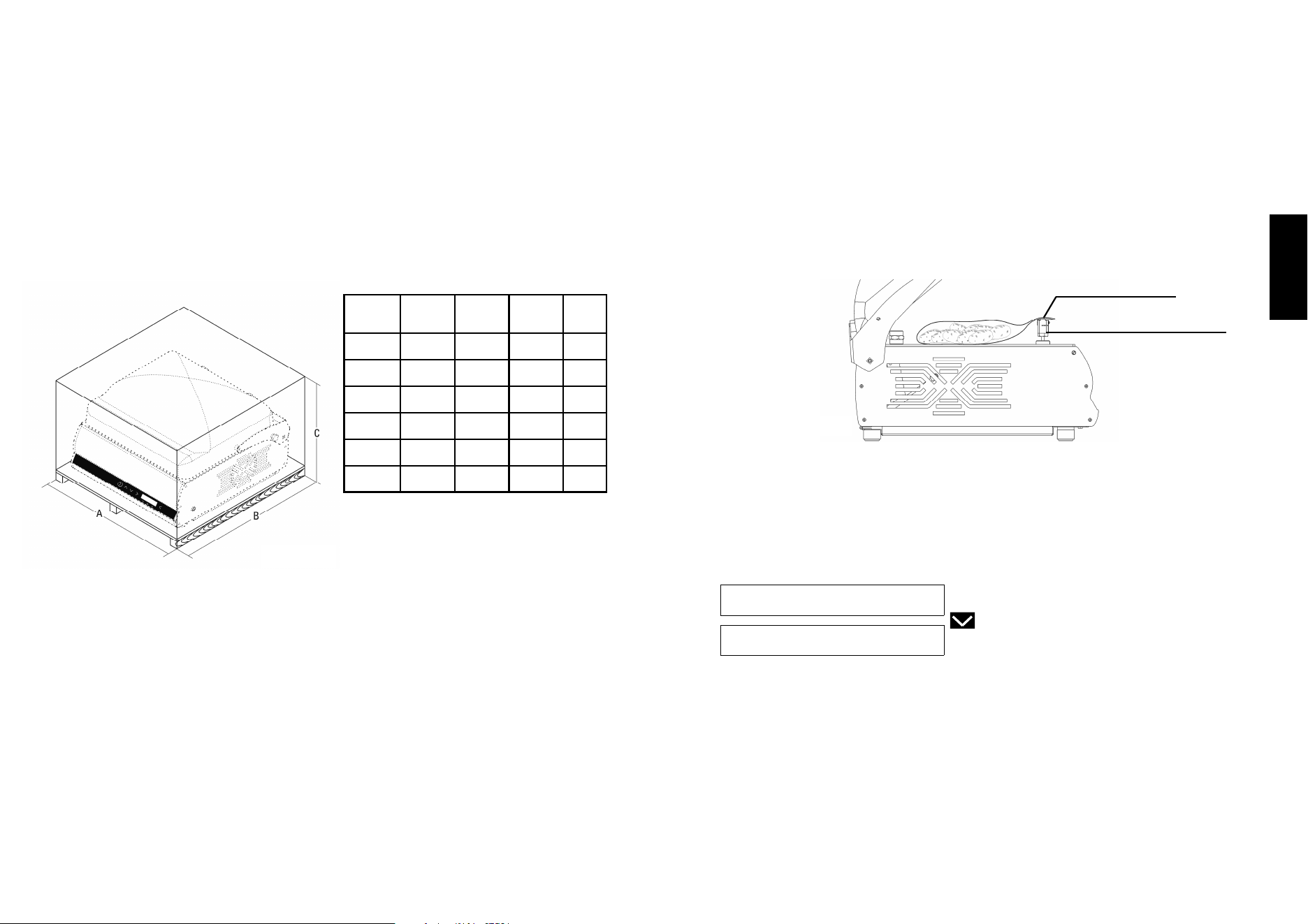
2.4 - Wiring diagram
Fig. 2.4.1
Wire map legend
1 = white
2 = white
3 = white
4 = white
5 = black
6 = orange
7 = white
8 = red
9 = yellow
10 = blue
12
3 Inspection, transport, delivery and installation
3.1 - Inspection
The machine you own has been inspected at our establishment in order to certify
correct operation and adjustment.
3.2 - Delivery and handling the machine
All material delivered has been accurately controlled before consignment to the
carrier.
Unless agreed differently with the Customer or for particularly onerous transport,
the machine is wrapped in nylon and cardboard.
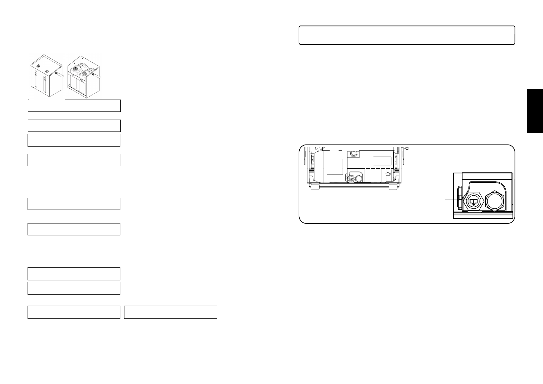
The packaging dimensions are given in fig. 3.2.1
On receipt of the machine, check the integrity of the packaging.
If the packaging is damaged, sign the documents for receipt with the following
note:
"Accepted subject to checking..." and the reason.
Open the packaging, and in the presence of machine components that are really
damaged, make a claim to the carrier within three days from the date indicated on
the documents.
3.3 - Installation
After having removed the packaging, check the integrity of the machine.
In particular, check that the machine is integral and without visible damage, which
could have been caused during transport.
If in doubt, do not use the machine and contact the Manufacturer.
Place
A B C
Gross
weight
mm mm mm Kg
30
720 570 770 57
40
760 640 770 67
50
840 870 750 84
70
1200 800 720 128
70 P
1200 800 1350 180
Fig. 3.2.1
21
English
4.4 Vacuum packaging
After making all the primary settings, the machine is ready for use.
- Connect the machine to the mains power.
- Unscrew the black knob on the right side of the machine to free the
hood in order to start operation.
- Power up the machine with the switch on the right side. The display will turn on
and show the main screen.
- Use the up and down arrows to scroll through the list of preset programs
- Place the bag on the surface with the open side resting perfectly flat
on the sealing bar.
- Lower the hood and apply firm pressure to keep it
closed and start the operating cycle. When packaging with an external
vacuum,
press the start
button to start
the cycle.
4.4.1 Automatic packaging
The machine offers automatic packaging by default. You can choose from a list of
preset programs and a list of timer programs from 0 to 9 that you can set according
to your time preferences.
Use the up and down arrows to scroll
through the list and choose the most suit-
able program.
Close the hood, and the machine will start the
vacuum packaging process.
Preset programs
To edit the settings in these programs, press the right arrow; the vacuum value
(100%) will start flashing.
Use the up and down arrows to edit this value from 50 to 100%.
Press the right arrow; the sealing time (5.0) will start flashing.
Use the up and down arrows to edit this value in steps of 1/10 second.
A U T
1 0 0
O M A
% 5
T I C S E
. 0 7 . 5
N S O R
S e c
L I Q
1 0 0
U I D
% 5
A U T O M
. 0 o f f
A T I C
S e c
SURPLUS BAG
SEALING BAR
Fig. 4.3.1
20
If instead the machine has the A.O.R. accessory,
press the down arrow to enter the A.O.R. menu.
4.3.12 A.O.R. Automatic oil replacement (optional)
This is a system that changes the oil automatically
using external tanks
connected to the pump
.
To execute the automatic oil replacement
cycle, select YES and follow the instructions
on the machine display.
The following text will scroll on the display:
“CONNECT OIL TANKS, CLOSE BLACK CAP
AND PRESS ON
”
The oil replacement process will start and the
display shows the text
The procedure ends when the oil in the pump reaches the maximum level.
The display shows the text “OIL REPLACEMENT FINISHED”
The machine emits a sound and returns to the last program used.
If, for any reason, the oil replacement cycles does not complete the cycle cor-
rectly, the machine display will show the fol-
lowing warning message:
CAUTION OIL REPLACEMENT FAILED, NO
OIL IN PUMP.
The oil replacement procedure can be re-
peated. The machine allows up to three con-
secutive attempts if the procedure fails
O I L
I N
R E
P R O
P L A C E M
G R E S S
E N T
O I L
F I N
R E
I S H
P L A C E M
E D
E N T
A T T
R E P
E N T
L A C
I O N O I
E M E N T
L
F A I L
R E P
T A N
L A C
K S !
E O I L
!
O I L
A U T
R E
O M A
P L A C E M
T I C N O
E N T
Y E S
C O N
C l o
N E C
s e
T O I L
b l a c k
T A N K
c a p
4.3.13 Settings shortcuts
You can use keyboard shortcuts for the main functions of the menu:
Press RIGHT arrow 3 times = preheating.
Follow the instructions on display
Press and keep RIGHT arrow for 3 seconds
= gas on/off
Press and
keep
LEFT
arrow = printer on/off
Press LEFT arrow 1 time = repeats last print (no instructions appear on display)
P R I
D e a
N T E
c t i
R
v a t e d
P R I
A c t
N T E
i v a
R
t e d
G A S
A c t
F L
i v a
U S H
t e d
O I L
C l o
H E
s e
A T I N G
b l a c k
C Y C L
c a p
13
English
Before carrying out any check that leads to the removal of some items, the plug
must be removed from the mains electricity.
3.3.1 - Disposal of the packaging
The packaging materials such as cardboard, nylon and wood are products similar
to solid urban waste. They can therefore be disposed of freely.
Nylon is a pollutant, which produces toxic fumes if burned.
Do not burn and disperse in the environment, but dispose according to the Laws in
force.
If the machine is in a country where there are particular regulations, dispose of the
packaging in compliance with that described by the Standards in force.
3.4 - Connections
Before start-up, check the oil level via the control window present on the pump.
Before connecting the packaging machine, make sure that the plate data
correspond with that of the mains electricity.
The plate is on the rear of the machine.
When the level has been checked and everything closed, connect the plug to the
230V socket.
In the event of incompatibility between the socket and plug, have the socket
replaced with a suitable one by professionally qualified staff.
In particular, the latter must check that the section of the cables is suitable for the
input power of the machine. In general, the use of adapters, multiple socket outlets
and/or extensions is not recommended.
Whenever their use is indispensible, only simple or multiple adapters and
extensions must be used that are in compliance with Safety Standards in force;
however paying attention not to exceed the capacity limit in terms of current value,
and the maximum power value marked on the multiple outlet.
Fig. 3.4.1
MAX
MIN
14
3.5 - Electrical system hook-up
ATTENTION!
- Make sure that its voltage matches the value displayed on the machine’s rating
Plate. All work on the electrical system of the machine must be carried out by
specialized staff duly authorized for its performance by the manager in charge.
Hook the machine to a power grid that has an efficient earthing connection.
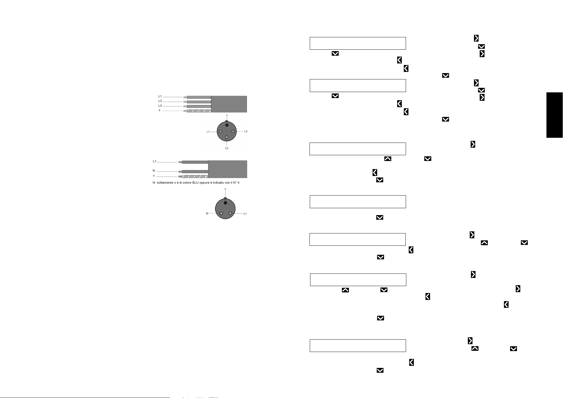
3.5.1 - 3-phase machine (220 V/60 Hz)
These machine versions include 11 AWG
power cable.
The power cable is plugged into a quadripolar
3-phase socket. Hook the cable to the 3-
phase power grid, interposing a 16 ampere differential circuit
breaker.
3.5.2 - Single-phase machine (230 V/60 Hz)
This machine version includes 16 or 12 AWG power cable. This
power cable is pulgged into a tripolar single-
phase socket. Hook the cable to a single-
phase 230 Volt-60 Hz power grid, interpo-
sing a 16 ampere differential circuit breaker.
For machine versions configured with a
different voltage, contact the manufacturer
for instructions. If there is need to extend the power cable, use a
cable with the same diameter as the one installed by the manu-
facturer.
In the three-phase connection line, at the installation time, check the motor fan
rotation. That must be the same as the one indicated by the arrow
19
English
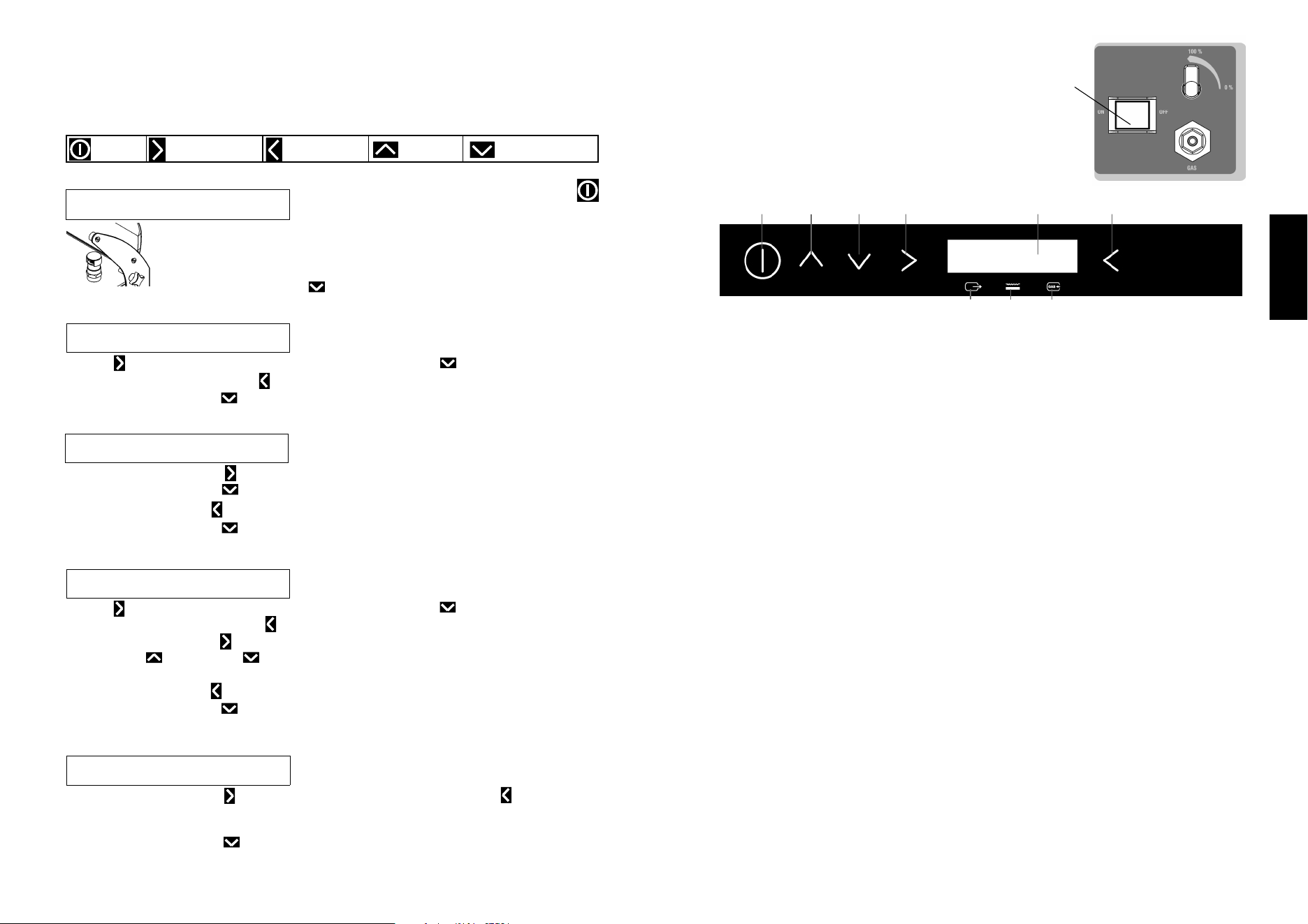
4.3.6 Label setting
Press the RIGHT arrow; the first letter will
start flashing. Use the UP and DOWN
arrows to edit the individual letters. Press the RIGHT arrow to move to
the
next letter. Use the LEFT arrow to return to the previous letters and edit
them if nec- essary. Press the LEFT
arrow while on the first letter to exit from
editing
mode; nothing will flash. Press the DOWN arrow to proceed to the
next step.
Press the RIGHT arrow; the first letter will start flashing. Use the UP and
DOWN
1 S T
X x x
R O
x x
W L A B E
L
2 S T
V a c
R O
u u m
W L A B E
P a c k i
L
n g
4.3.11 Beeper tone setting
Press the RIGHT arrow; the set value
(High) will start flashing. Use the UP and
DOWN
arrows to select the preferred value from High, Medium, Low or Off. To confirm and
exit, wait 5 seconds or press the LEFT arrow to move until nothing is flashing.
B E E
H i g
P E R
h
T O N E
4.3.8 Vacuum sensor calibration
The vacuum sensor calibration will start as soon
as the hood is closed.
The hood opens when the calibration cycle has finished.
C A L
C l o
I B R
s e
A T I O N
l i d
S E N S
4.3.7 Language
Press the RIGHT arrow, to enter the
LAN- GUAGE menu. The word English will
start flashing. Use the ar- rows UP and DOWN to scroll through the lan-
guages in the
system to select the desired language.
L A N
E n g
G U A
l i s
G E
h
4.3.9 Reset WiFi
Press the RIGHT arrow
The word
NO
will start
flashing. Use the arrows UP and
DOWN to select
YES.
Press the
LEFT arrow or wait 5 seconds to confirm
W I F
I R
E S E T
N O
4.3.10 Date and time setting
Press the RIGHT arrow.
The first number will
start flashing.
Use the UP and DOWN arrows to edit the numbers. Press the
RIGHT
ar-
row to
move to the next number. Use the LEFT arrow to return the previous numbers and edit
them if necessary. To confirm and exit, wait 5 seconds or press the LEFT arrow to
D A T
2 5 -
E A
0 6 -
N D T I M
2 0 1 8 1
E
3 : 3 5
18
4.3 User menu
Press the ON key and hold it down for 3 seconds to enter the user menu.
Use the arrow keys to display the list of machine functions with values that can be
set or edited
.
4.3.1 Oil heating and cleaning
The text “Close black cap and press ON key”
scrolls on the second line of the display. Follow the instructions.
The machine will start the oil heating process to bring it to the preset
temperature of about 50 °C.
Pressing the ON-OFF key will stop the cycle.
O I L
C l o
H E
s e
A T I N G
b l a c k
C Y C L
c a p
LEFT arrow
UP arrow
DOWN arrow
ON-OFF
RIGHT arrow
4.3.2 Printer setting
The second line of the display shows the text
“Activated” continuously. Press the RIGHT
arrow; the text will start flashing. Press the DOWN arrow to de-
activate the
P R I
A c t
N T E
i v a
R
t e d
4.3.3 Inert gas setting (where provided)
The second line of the display shows the text
“Activated” continuously.
Press the RIGHT ar- row; the text will start flashing.
Press the DOWN arrow to deactivate the gas.
Press the LEFT arrow or wait 5 seconds to confirm the change.
Press the DOWN arrow to proceed to the next function.
G A S
A c t
F L
i v a
U S H
t e d
4.3.4 Label counter
The second line of the display shows the text
“Activated” continu- ously. Press the
RIGHT
arrow; the text will start flashing. Press the DOWN arrow to deactivate the
counter. Press the LEFT arrow or wait 5 seconds to confirm the
change.
Press the RIGHT arrow twice; 1/0000 will start flashing.
Use the UP and DOWN arrows to set the maximum number of labels to
L A B
A c t
E L
i v a
C O U N T E
t e d 1 /
R
0 0 0 0
4.3.5 Label counter reset
The second line of the display shows the text
“Reset” continuously.
Press the RIGHT arrow; the text will start flashing. Press the LEFT arrow or
wait 5 seconds to confirm the change.
The counter will be reset even if it has not reached the value set previously.
Press the DOWN arrow to proceed to the next function.
L A B
R e s
E L
e t
C O U N T E
R
15
English
4 Using the machine
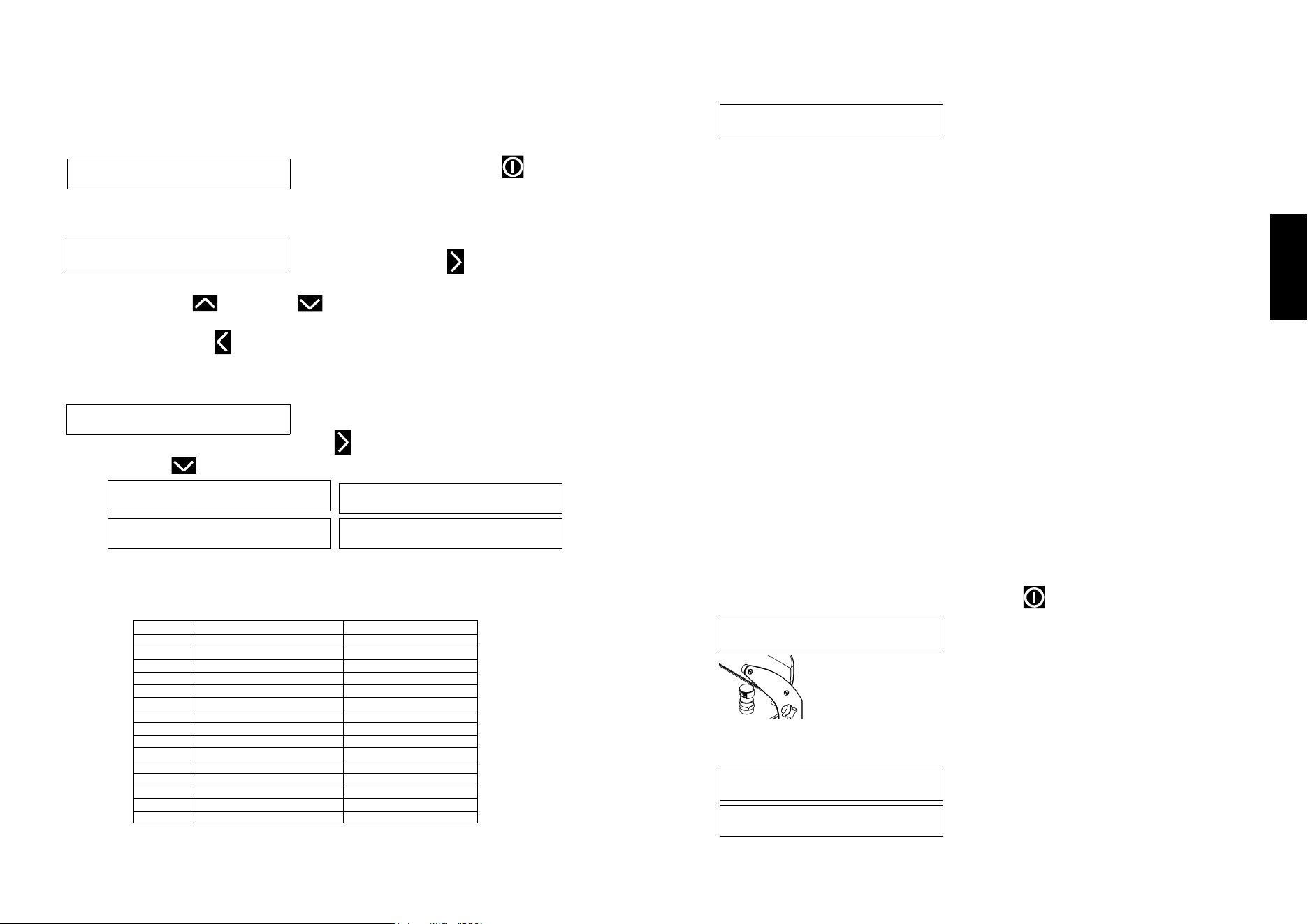
4.1 - Key to controls
1. - Main machine ON-OFF switch.
This switches the machine on and off.
It is located on the side of the machine.
2. - Board on or off.
This lights blue when the main machine switch is
in the ON position. It can have three colours.
Blue light: when the machine is on but the board is disabled
while setting the menus
Green light: when the machine is active and ready for use
Red light: when the machine is operating
3-4. - Scroll the software menus
- Select the stored or automatic programs.
- Increase or decrease the selected values (where permitted):
percentage suction, vacuum time, sealing time, gas injection
time (where provided).
5. - Opens the machine programming menu.
6. - Analogue display.
A = suction time
B = sealing time
C = gas injection time
7. - Confirms a selection.
CAUTION! Changes are stored automatically. The control system exits from the
current menu five seconds after setting a value.
It is recommended to turn off the power switch, the mains switch or
disconnect the plug only in case of maintenance or specific operations
specified in the manual. The equipment does not need to be turned off after
each use, it automatically switches to stand by mode and energy saving
mode without removing the power supply. When the equipment remains
connected to the power source, all the control functions are active and this
guarantees better functionality and longer life.
1
Fig. 4.1.1
Fig. 4.1.2
2
A B C
3 4 5 6 7
16
4.2 First power-up, installation settings
CAUTION! All the functions and settings described below are MANDATORY.
They must be carried out with the machine powered (main switch ref. 1 in fig. 4.1.1.
in the ON position) and the board off. The board on key light is blue and the display
shows the HW version and FW version.
If the board is on, press ON key before
carrying out the following operations.
4.2.1 MENU language setting
A few seconds after switching on the machine,
the display shows:
English is set by de- fault.
Press the RIGHT arrow, to enter the
LANGUAGE menu.
The word English will start flashing.
Use the arrows UP and DOWN to scroll through the languages in the
system to select the desired language.
Press the LEFT arrow, to store the change and proceed with the next settings.
4.2.2 Use type setting
Select the packaged product type so that the
soft- ware can calculate the filter change
and oil change cycle times. For a few seconds the display shows
Then the dis- play shows a list of products.
The se-
lected text flashes. Use the RIGHT arrow to select YES or NO
Use the DOWN arrow to confirm the choice and proceed to the next product.
Once the type of packaged
product has been se-
lected, the filter change
and oil change cycle
times are calculated as
follows:
L A N
E n g
G U A
l i s
G E
h
C h o
u s a
o s e
g e
p r o d u
c t
P R O
D r y
D U C
T
Y E
S - N O
X X X
H W
X X
4 . 0
X X X X
F W 3 .
0
P R O
P o w
D U C
d e r
T
Y E
S - N O
P R O
L i q
D U C
u i d
T
Y E
S - N O
P R O
H o t
D U C
T
Y E
S - N O
cycles to OIL change
h of use to FILTER change
S
7000 500
S+L
3000 300
S+C
2000 200
S+P
2000 100
S+L+P
2000 100
S+C+P
2000 100
S+L+C+P
2000 100
C
1000 200
C+L
1500 200
C+P
1000 100
S+L+C
1500 200
L
2000 300
L+P
2000 100
L+P+C
1000 100
P
1000 50
17
English
4.2.3 Vacuum sensor calibration
After setting the packaged products with the down arrow, the display shows:
The vacuum sensor calibration will start as soon as the hood is closed.
This process serves to align the sensor with the pressure at the place of
installation. The hood opens when the calibration cycle has finished.
It is advisable to repeat the procedure if there is a power failure or the calibration
cycles is interrupted.
NOTE: The machine has a very accurate “relative pressure” sensor, allowing it to
manage the optimal operating time automatically without the need for trials or man-
ual settings.
The relative pressure is the difference between the local atmospheric pressure and
the desired final vacuum pressure (which can be selected from 1, 5, or 10 Mb).
The relative pressure depends on the atmospheric pressure at the place where the
machine is installed, and may differ from that where the machine was manufactured
and tested (20 m a.s.l. with an average pressure of 1020 Mb).
The pressure decreases significantly with an increase in altitude and the sensor may
have difficulty in making measurements, which will affect the percentage vacuum
shown on the display. The machine operation does not change, the pump is not af-
fected in any way, and the actual pressure in the chamber will be the same or lower
than that obtained in the manufacturing site for the same operating time.
However, it does create the following problem: even when the chamber has reached
the requested vacuum, the display continues to show a lower vacuum level, and so
the pump will continue to operate continuously.
A sensor calibration program has been provided to realign the sensor with the new
pressure condition in the place of installation due to the different altitude and pres-
sure from those at the manufacturing site.
4.2.4 Oil heating
Once the sensor calibration cycle has finished, the machine automatically pro-
ceeds to the oil heating process.
The text “Close black cap and press ON button”
scrolls on the second line of the display. Follow
the instructions.
The machine will start the oil heating process to bring it to the preset
temperature of
about 60 – 65 °C.
Once the oil heating process has finished, the machine is in the best
operating conditions.
After a few seconds, the display shows
:
C A L
C l o
I B R
s e
A T I O N
l i d
S E N S
O I L
C l o
H E
s e
A T I N G
b l a c k
C Y C L
c a p
R
E
A
D
Y
T
F
O
R
U
h
a
n
k
s
S
E
A U T
1 0 0
O M A
% 5
T I C S E
. 0 7 . 5
N S O R
S e c