YB418 Instruction Manual
2026-04-27 Protocol 2 / 5S Protocol
Dear User:
In order for you to use the instrument better, please read the
YB418 User Manual carefully.
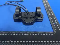
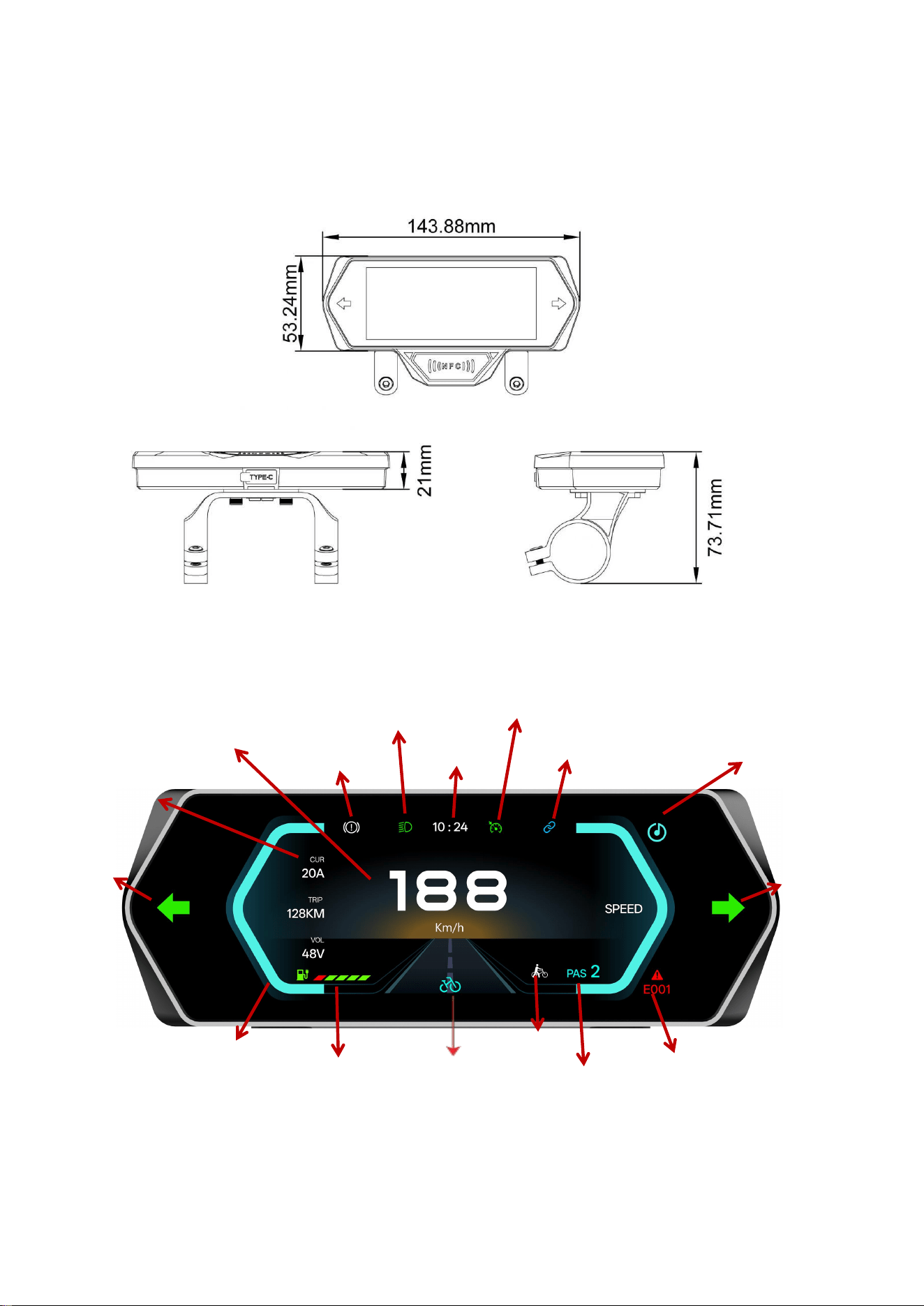
Outer size:
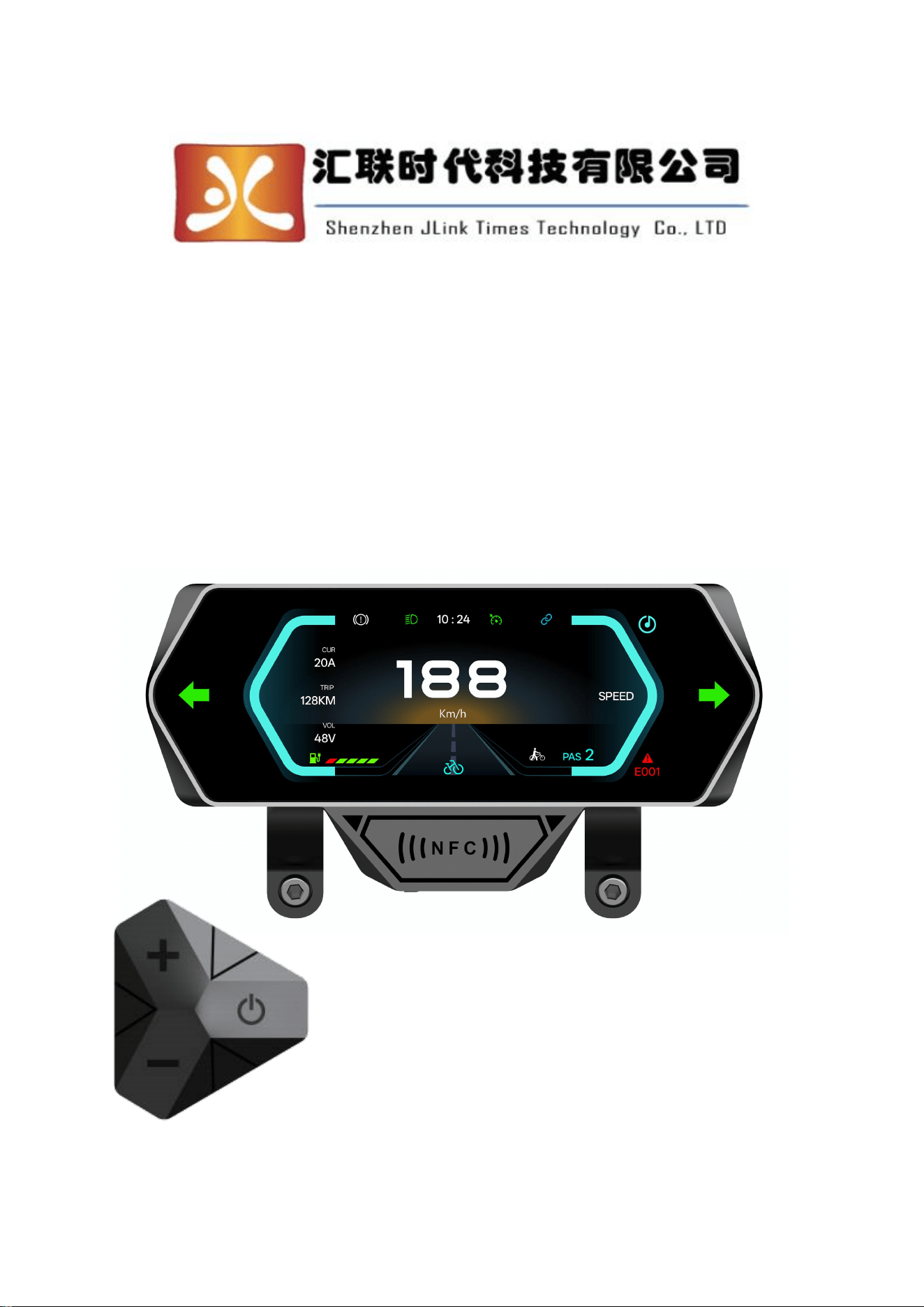
Description of the display interface:
Speed
Brakes
Headlights
Time
Cruise control
APP Bluetooth
Bluetooth Music
Right Turn
Fault Code
Gear
Boost
Drive Mode
Battery
Speed Bar
Function Area
Left Turn
Operation Instructions for YB418 Instrument
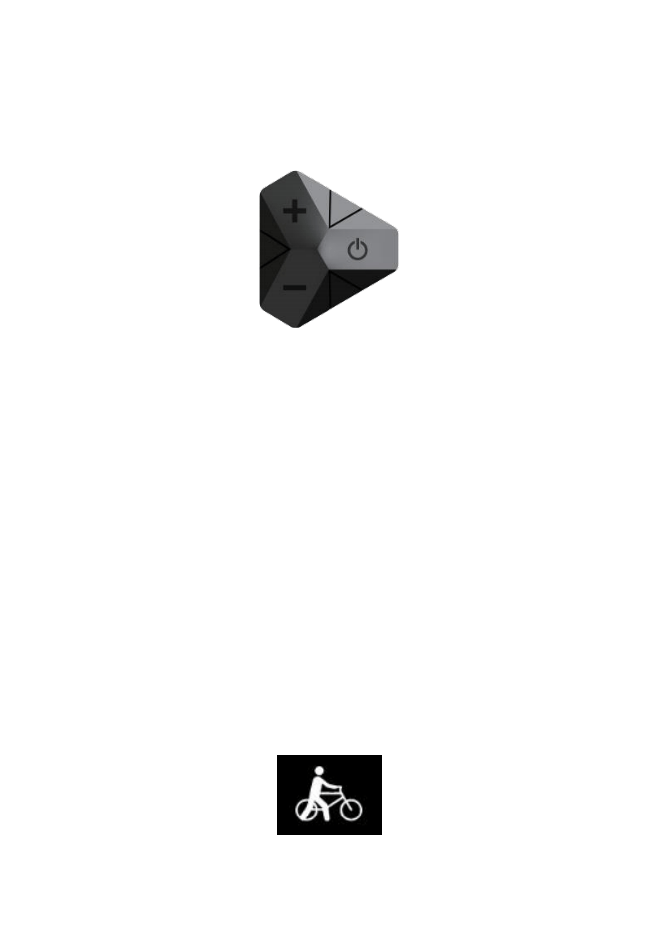
Key Defi nition:
The instrument's supporting handle has a total of three keys. They are the power-on/mode
key (M), the plus key (+), and the minus key (-)
Power on:
Under the electrified state, press and hold the power-on key for 5 seconds to power on.
Power off:
Under the electrified state, press and hold the power-on key for 5 seconds to power off.
Selection of Assist Levels:
Short press the plus (+) key or the minus (-) key to switch the assist level of the electric
bike. The power range is from 0 to 5 gears. Gear 1 is the lowest power, and Gear 5 is the
highest power. The gear position is determined by the manufacturer for the twist grip/as-
sist gear, and the default is Gear 1.
The total number of gears and the value of each gear can be adjusted in the settings inter-
face. Refer to the settings interface.
Assisted Pushing:
Long press the (-) key for 3 seconds and the electric bike enters the power-assisted push-
ing state. The electric bike travels at a speed of 6 kilometers per hour. Long press for
another 3 seconds or squeeze the brake to immediately stop the powerassisted pushing.
Turn on/off the headlight:
Long press the (+) key for 3 seconds to turn on/off the headlight. (If the light sensor is
selected, the headlight will be automatically turned on or off through the light sensor on
the front of the instrument.)
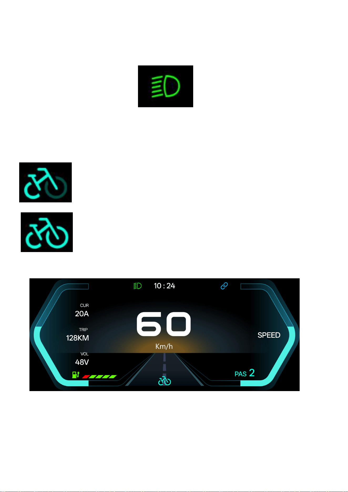
Display Indication of Dual-Drive Mode:
Short press the power button twice to switch the drive mode.
Rear-wheel Drive:
Dual Drive:
Speed Display:
When working normally and in a no-fault state, the current speed is displayed:
Short press the power key to switch to the flashing of AVG and MAX. Select AVG or MAX
through the (+) key and (-) key. Click the power key again or wait for 8 seconds to automat-
ically confirm the speed to be displayed.
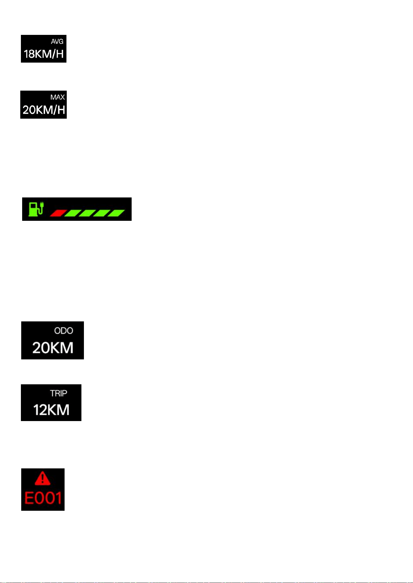
AVG:Current Average Riding Speed.
MAX:Current Maximum Riding Speed.
Battery Power Display:
The battery power is displayed based on the set battery voltage (for details, see the set-
tings interface). When the model supports BMS, the battery power is subject to BMS, and
the estimated battery power of the instrument becomes invalid.
Mileage Display:
The instrument displays the total mileage from the factory and the mileage of a single
ride.Short press the power key to switch to the flashing of the mileage unit. Select ODO or
TRIP through the (+) key and (-) key.Click the power key again or wait for 8 seconds to
automatically confirm the mileage to be displayed.
Total Mileage (ODO): The total mileage from the factory to the present.
Single Mileage (TRIP): The riding mileage after this startup, and it will be automatically
reset to zero after
Error Code Display:
When a fault occurs in the electronic control system of the electric vehicle, the fault light
comes on and the fault code is displayed at the speed position.
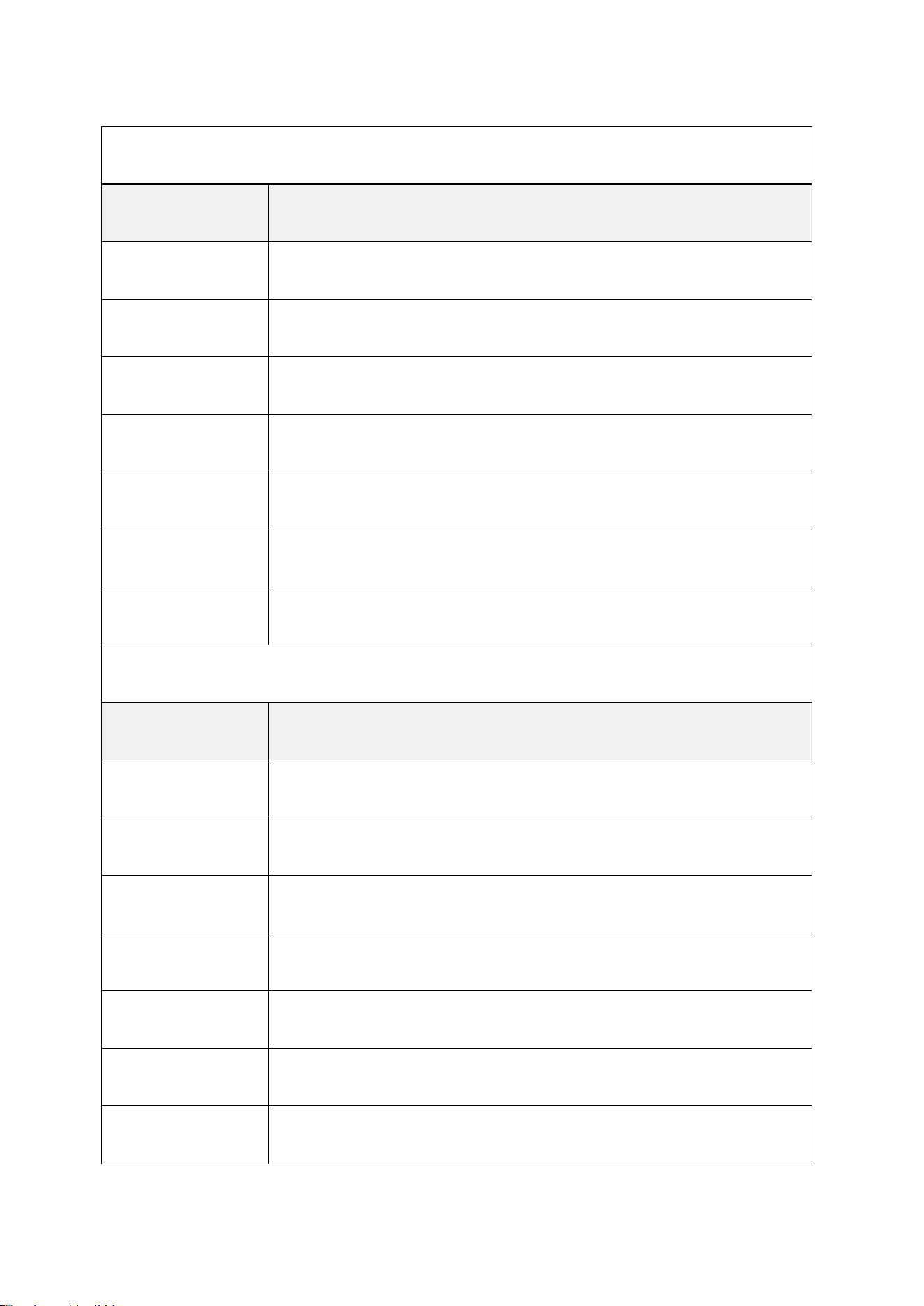
Fault Code for Protocol No. 2
Fault Code
Fault Name
E06
Under-voltage Fault
E07
Motor Fault
E08
Throttle Fault
E09
Controller Fault
E10
Communication Receiving Fault
E11
Communication Sending Fault
E12
Brake Fault
5S Protocol Fault Code
Fault Code
Fault Name
E06
Under-voltage Fault
E30
Communication Fault
E33
Current Fault
E34
Throttle Fault
E35
Motor Fault
E36
Motor Hall Fault
E37
Brake Fault
Setting Parameters:
The setting interface may vary depending on the adapted vehicle model and
controller, but the specific setting items remain consistent. As some manufacturers
customize the accessible settings, the settings listed below may not be available on
all meters. Certain setting items may also be removed for safety reasons.
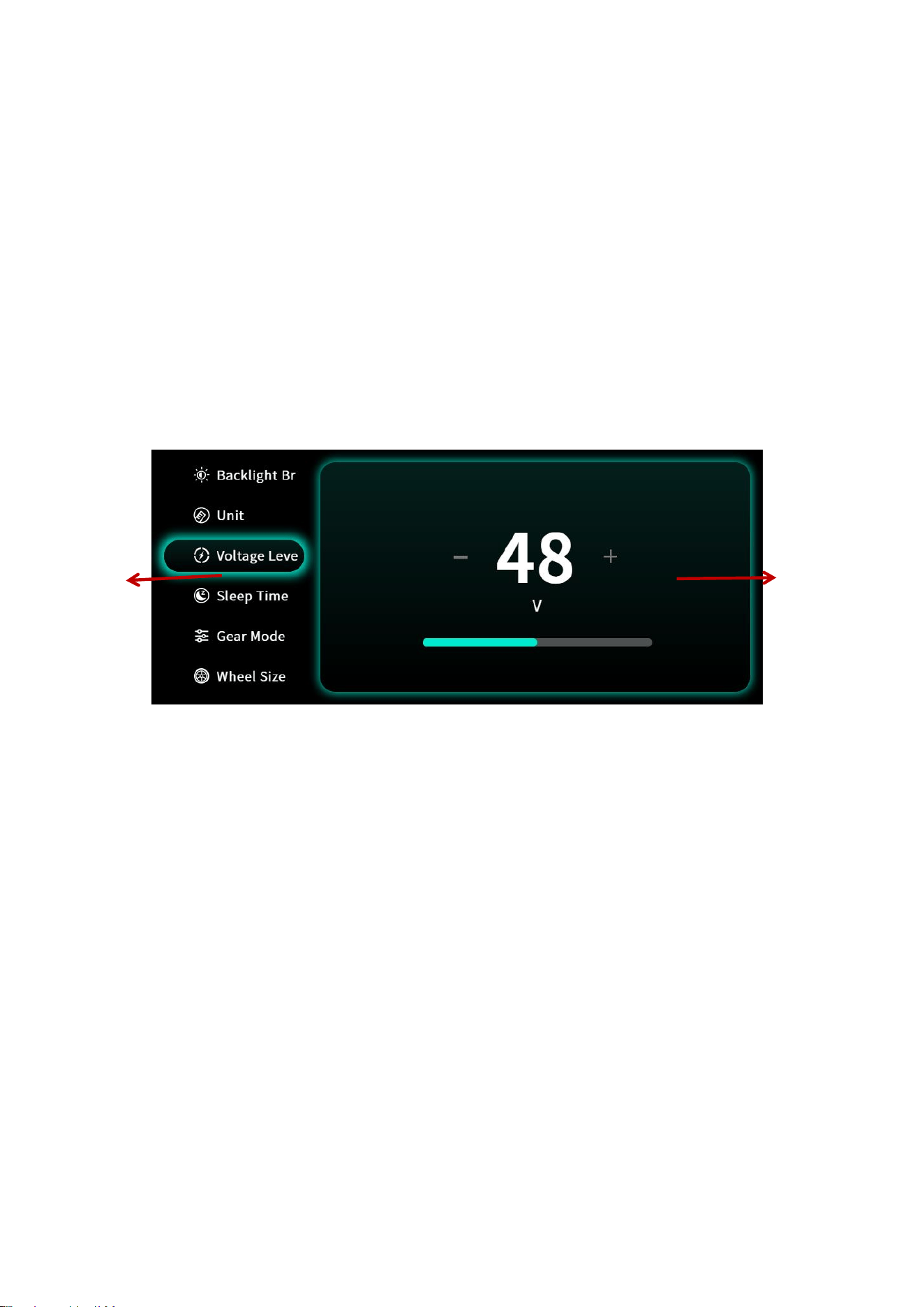
Entering the Setting Menu: When the device is powered on, the vehicle is stationary,
and the meter is functioning normally, press and hold both the (+) and (-) keys for 3
seconds to enter the setting interface. The setting code will be displayed in the
middle speed area. Short-press the power key to switch between function gear
values, use the (+) and (-) keys to adjust the values, then press and hold both (+)
and (-) keys for 3 seconds to save manually or wait 8 seconds for automatic saving.
All gear and value changes will be shown in the digital display area at the bottom left.
In the setting interface, it will automatically exit if there is no operation for 8 seconds.
Parameter Description:
1:Backlight Brightness: 1 - 4: Manually adjust the backlight brightness from level 1 to
level 4.
2:Mileage Unit’0:KM;1:MILE;
3:Voltage Grade:24V’36V’48V’60V;
4:Sleep Time:0’No Sleep;
Other numbers represent the sleep time, ranging from 1 to 60; unit: minutes;
5:Power Assist Gear: 0, 3-Gear Mode;
1, 5-Gear Mode;
6 : Tire Diameter:unit’inch;
Value of Tire Diameter:5.0~50 accuracy:0.1 inch
This parameter is related to the speed displayed on the instrument and needs to be input
correct- ly.;
7 : Number of Speed Measuring Magnetic Steels:Range:1-100;
Set
Parameter
Set Value

This parameter is related to the speed displayed on the instrument and needs to be input
correct- ly.
If it is an ordinary hub motor, directly input the number of magnetic steels.
If it is a high-speed motor, the reduction ratio also needs to be calculated. The input
data = number of magnetic steels × reduction ratio
For example: The number of motor magnetic steels is 20, and the reduction ratio is 4.3: The
input
data is: 86 = 20 × 4.3.
8:Speed limit: Protocol No. 2, Range 0 - 100 km/h. 100 indicates no speed limit;
The input data here represents the maximum operating speed of the vehicle: For example, if
25 is input, it means that the maximum operating speed of the vehicle will not exceed 25
km/h; the
driving speed is maintained at the set value.
Error: ±0 km/h; (Both power assist and handlebar are subject to speed limit)
Note: The values here are based on kilometers.
9::Zero-start and non-zero-start settings,0:Zero-start;1:Non-zero-star;
10:Drive mode setting.(Only valid for Protocol 2)
0:Power-assisted drive (The amount of power assistance output is determined by
the power assist gear. At this time, the handlebar is invalid).
1:Electric drive (Driven by the handlebar. At this time, the power assist gear is invalid).
2:Power-assisted drive and electric drive coexist simultaneously.
11:Power assist sensitivity setting.(Only valid for Protocol 2) Range: 1 - 24;
12:Power assist start intensity setting. Range: 1 - 5;
13:Power assist magnetic steel disc type setting. Three types: 5, 8, and 12
magnetic steels.
14:Controller current limit value setting. Range: 1 - 20A
15:Controller undervoltage value.
16:Reset settings: Long-press the + key for 5 seconds to clear the ODO; long-press
the - key for 2 seconds to restore the factory settings.
17:Cruise enable: 0: Cruise not enabled, 1: Cruise enabled; Automatic cruise is
optional.
18:Display speed ratio adjustment range: 50% - 150%.
19:0 gear enable bit. 0: There is gear 0. 1: There is no gear 0.
20: (Only valid for 5S protocol) First gear PWM (this value affects speed)
21: (Only valid for 5S protocol) Second gear PWM (this value affects speed)
22: (Only valid for 5S protocol) Third gear PWM (this value affects speed)
23: (Only valid for 5S protocol) Fourth gear PWM (this value affects speed)
24: (Only valid for 5S protocol) Fifth gear PWM (this value affects speed)
25: (Only valid for 5S protocol) 6KM boost PWM (this value affects speed)
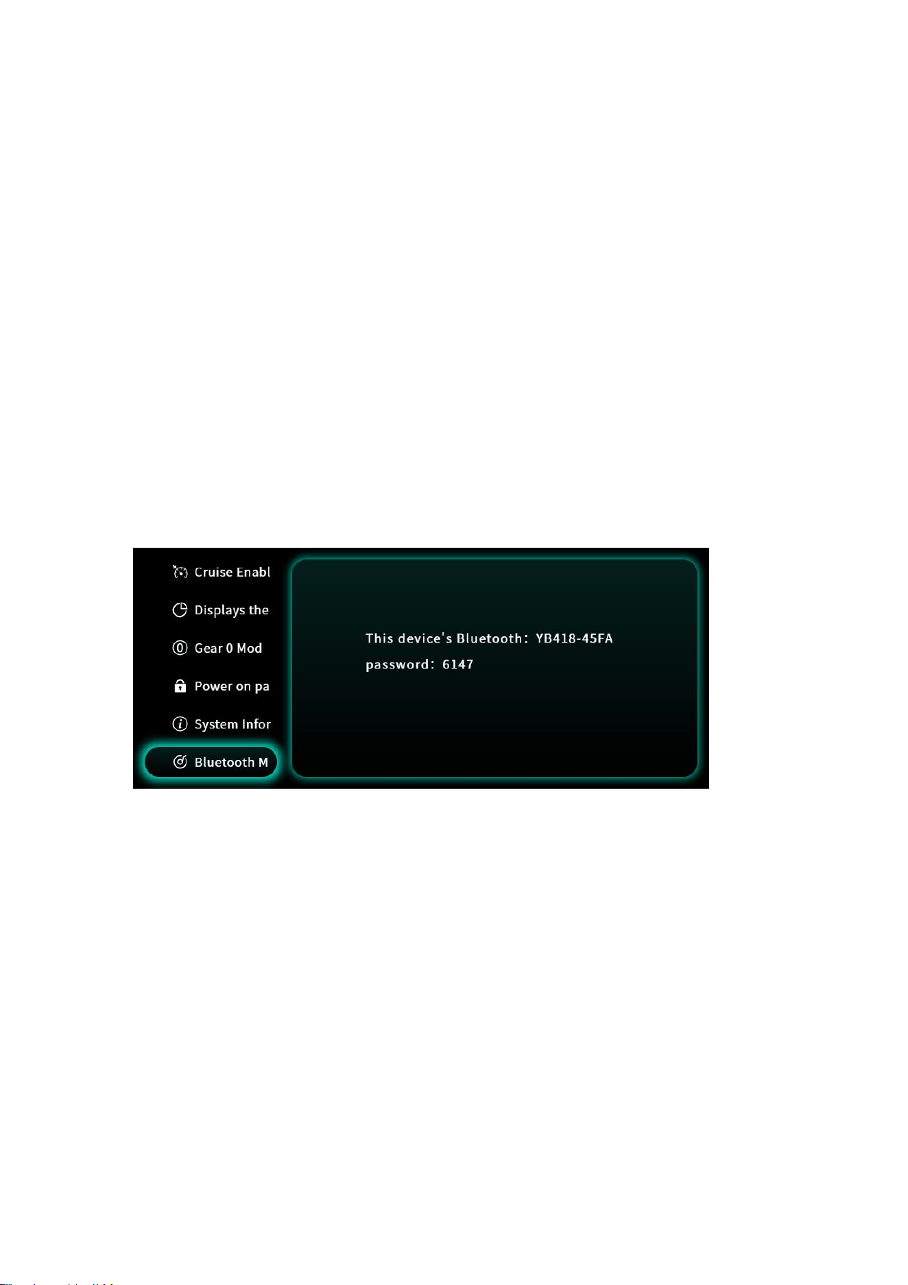
26: Power-on password setting: 0: Off, 1: On;
27.Music Playback: Turn on your phone's Bluetooth, find the device Bluetooth shown
in the picture, enter the password displayed in the image, and you can connect to
Bluetooth Music.
28. Connect APP.
29. System Language: Chinese, English.
30. NFC Binding.
31.Time Display.
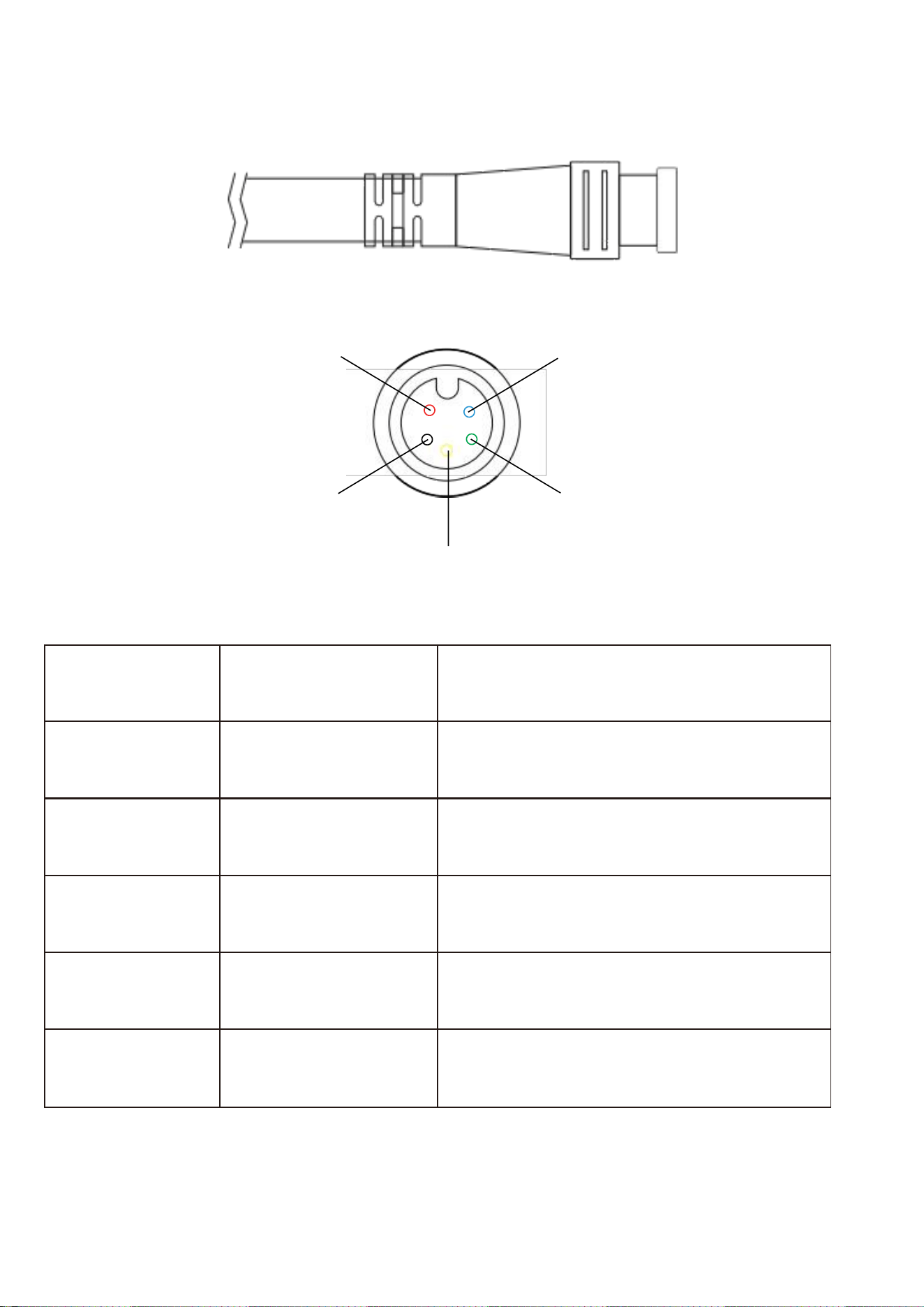
Connection line description :
Note: The product connection line adopts a waterproof plug, and users cannot see
the color of the lead wire inside the line
Lead wire
number
Color
Function description
1
Red(VCC)
Connect to the positive electrode
of the battery B+
2
Black(GND)
Connect to the negative electrode
of the battery B-
3
Yellow(TX)
Data transmission
4
Green(RX)
Data reception
5
Blue(K)
Electric door lock
1
2
3
4
5

Remarks & Instructions:
The content of this instrument manual is compiled based on the current product version, aiming
to guide users in understanding the instrument's basic functions, operation methods, and
interface display logic.
As the product will undergo continuous iteration and optimization, the instrument's interface
layout, function details, etc., may be adjusted with version updates, but this will not affect your
normal use. Meanwhile, in response to the customized needs of different customers, there may
also be differences in the instrument's setting item parameters and ranges (such as speed, battery
level, mileage, etc.).
In actual use, please refer to the physical status, latest display interface, and customized
parameters of the instrument you purchased. This manual is for reference only and does not
constitute a final functional commitment.

FCC Warnning:
This equipment has been tested and found to comply with the limits for a Class B digital device,
pursuant to part 15 of the FCC Rules. These limits are designed to provide
reasonable
protection againstharmful interference in a residential installation. This equipment generates,
uses and can radiateradio
frequency
energy
and,
if
not
installed
and
used
in
accordance
with
the
instructions,
maycause
harmful
interference
to
radio
communications.
However,
there
is
no
guarantee
thatinterference
will
not
occur
in
a
particular
installation.
If
this
equipment
does
cause
harmfulinterference to radio or television reception, which can be
determined by turning the equipmentoff
and
on,
the
user
is
encouraged
to
try
to
correct
the
interference
by
one
or
more
of
thefollowing measures:
•
Reorient or relocate the receiving antenna.
•
Increase the separation between the equipment and receiver.
•
Connect the equipment into an outlet on a circuit different from that to which the receiver is
connected.
• Consult the dealer or an experienced radio/TV technician for help.
Caution:
Any
changes
or
modifications
to
this
device
not
explicitly
approved
by
manufacturer
could void your authority to operate this equipment.
This
device
complies
with
part
15
of
the
FCC
Rules.
Operation
is
subject
to
the
following
two
conditions:
(1)This
device
may
not
cause
harmful
interference,
and
(2)
this
device
must
accept
any
interference received, including interference that may cause undesired operation.
This
equipment
complies
with
FCC
radiation
exposure
limits
set
forth
for
an
uncontrolled
environment.
This
equipment
should
be
installed
and
operated
with
minimum
distance
20cm
between the radiator and your body.