
QUICK SETUP GUIDE
Read this guide carefully before installing the product and make
sure you understand all of the content.
ENGLISH
Scan the QR code above
for installation guide video.
Scan the QR code above
for Multilingual QSGs.
95811 ES-A2522Z3-1
1
READ BEFORE INSTALLATION
Disclaimer
All products, product specifications and data are subject to change without prio notice to improve reliability, function, design or other aspects.
READ BEFORE INSTALLATION .............................................................................................................................. 1
Important Information ...................................................................................................................................................................1
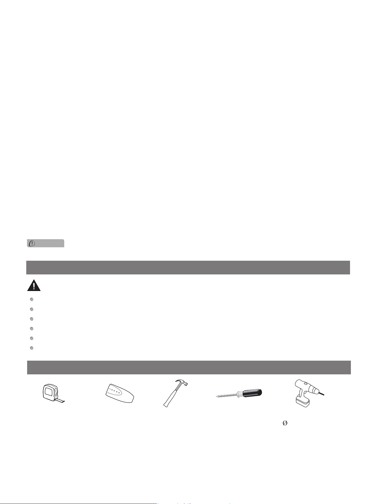
Required Tools(not included)
.......................................................................................................................................................1
ASSEMBLING THE SCREEN ................................................................................................................................... 2
Space for Assembling Screen ......................................................................................................................................................2
Preparation
..................................................................................................................................................................................2
I. Assemble the Inner Frame
........................................................................................................................................................2
II. Assemble the Screen
............................................................................................................................................................... 4
III. Assemble the Outer Frame
..................................................................................................................................................... 7
WALL MOUNT BRACKET INSTALLATION .............................................................................................................. 9
Installation Space ........................................................................................................................................................................9
Install the Wall Mount Bracket
.....................................................................................................................................................9
Maintain the Screen
................................................................................................................................................................... 11
Electric drill
5/16 inch(8mm)
Phillips screwdriver
Required Tools (not included)
Tape measure Stud nder
Hammer
Important Information
Do not touch or wipe the screen directly by hands or with an ordinary towel.
Do not expose the screen to dripping or splashing.
Do not place the screen on an unstable cart, tripod or desktop. Dropping may cause serious damage and injuries.
Do not scratch or touch the screen with hard or sharp objects.
Do not expose the screen to direct sunlight.
Do not place the screen near inflammable, explosive and other dangerous objects.
WARNING
CONTENTS
2
ASSEMBLING THE SCREEN
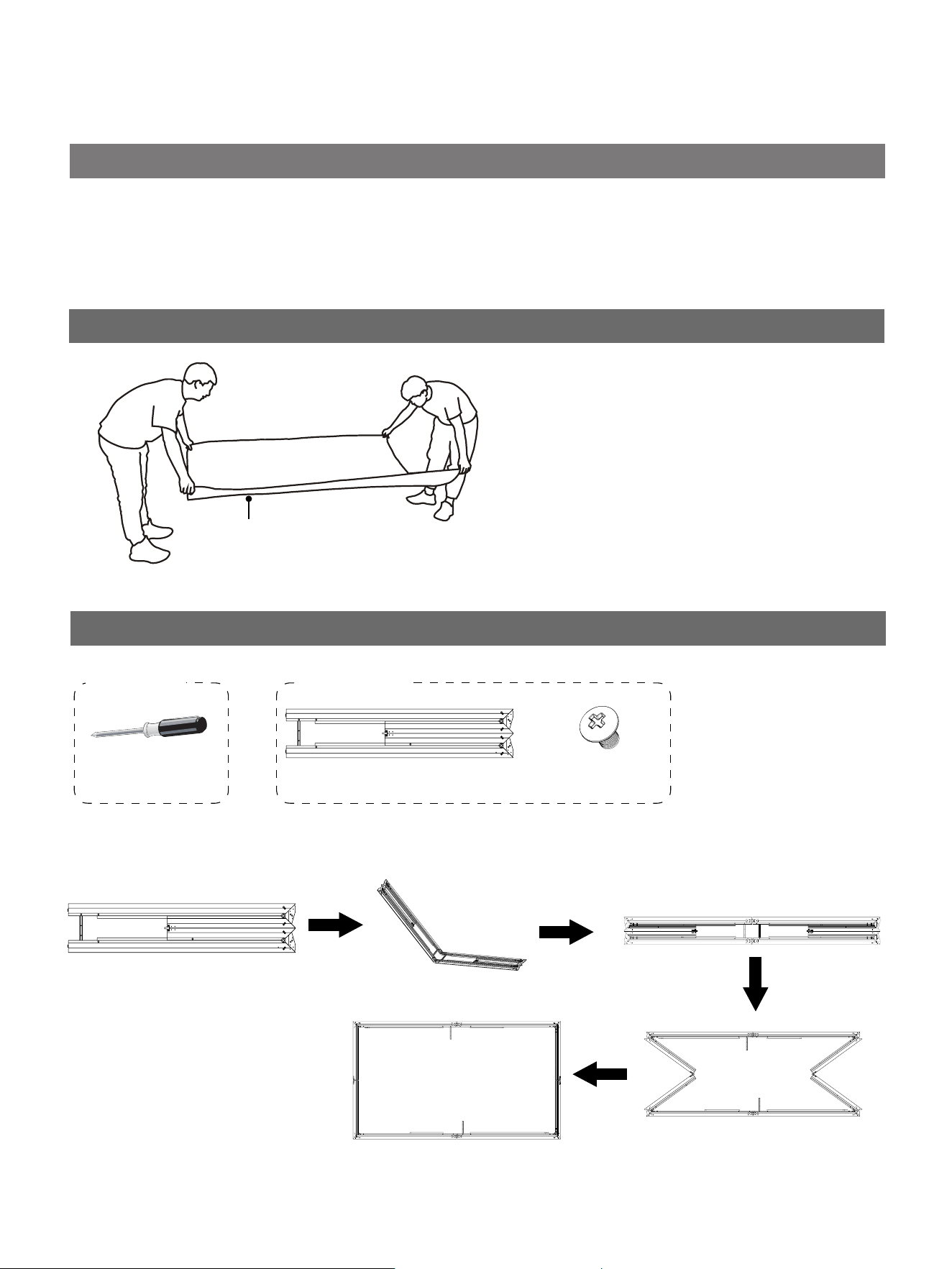
white protective sheet(Q)
Preparation
Before installation, spread out the
white protective sheet(Q) on the floor
and make sure that there is no sharp
or hard objects, or bulges on the floor.
I. Assemble the Inner Frame
Phillips screwdriver
Required tool
(not included)
Space for Assembling Screen
Before the installation, make sure you have enough space for assembling the screen.
The space should be larger than 3m × 2.5m(118.1 in. × 98.4 in.).
inner frame
M4
×
6 screw (M)
×
28 (Black)
Required parts
1. Unroll the inner frame.
3
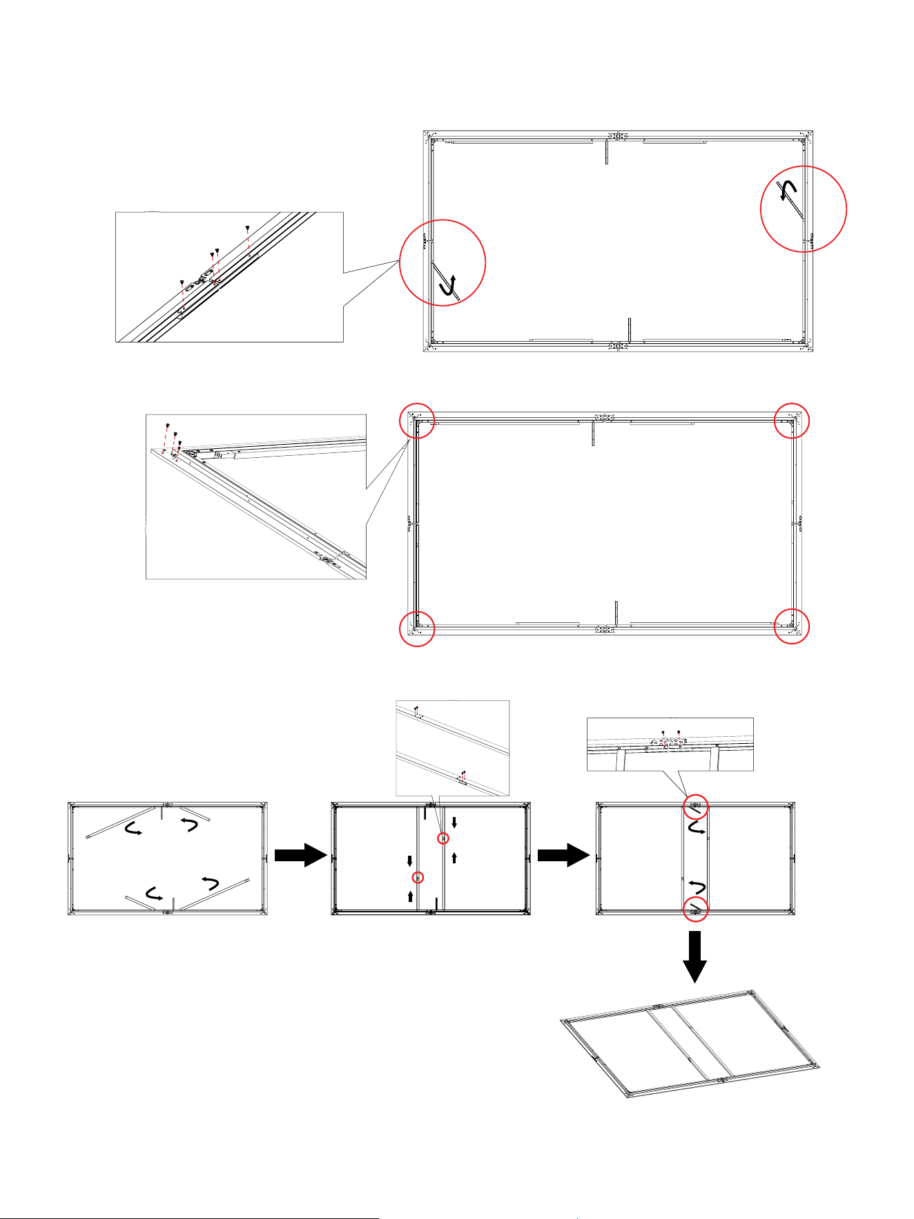
4. Unfold the vertical beams and tighten them with M4×6 screws(M). Then unfold the two long side support braces hidden in
the inner frame and tighten them with M4×6 screws(M) .
2. Unfold the two short side support braces hidden in the inner frame and tighten them with M4×6 screws(M).
M
3. Tighten the four corners of the inner frame with M4×6 screws(M) .
M
M
M
M
4
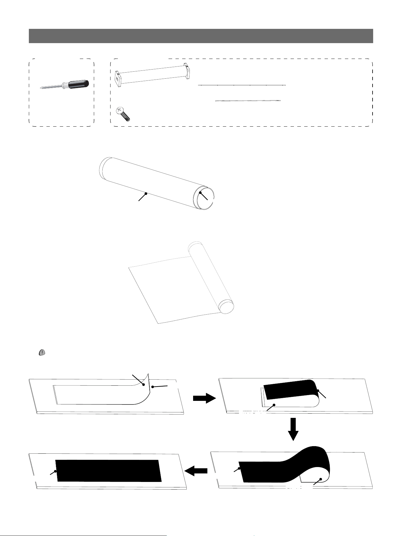
II. Assemble the Screen
Phillips screwdriver
short side tension rod(E)
×
2
screen
×
1
long side tension rod(D)
×
4
Required parts
Required tool
(not included)
screw (N)
×
24 (White)
Screen
Paper Tube
1. Two people with gloves are required to take the screen out of the packaging box.
2. Unroll the screen on the protective sheet and remove the covering on it to check if there are creases or scratches on the
surface of the screen.
Frontal side upwards
3. Two people stand on the two sides along the width direction and turn over the screen to make it face down.
NOTE: Handle with care to avoid damaging the screen.
Front side
Back side
Back side
Front side
Back side
Front side
Back side
5
4. Place the inner frame on the back side of the screen. Then adjust the position of the inner frame to centre it on the screen.
NOTE: There are positioning lines on the four corners of the back side of the screen.
5. Insert the two short side tension rods and the four long side tension rods into the sleeve of the screen.
Bottom
Long side
Long side
Short side Short side
D D
D D
E E
6. Fold the sleeves up towards the inner frame.
6
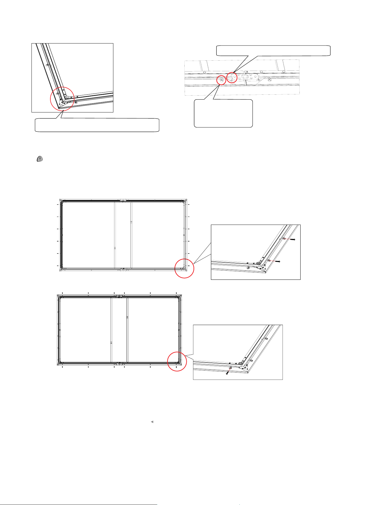
7. Position the screen by the location pins on the inner frame.
8. Put the screws(N) into the screw holes. Tighten the screw to secure the inner frame.
Position the tension rod by the location pin.
Align the hole on
the tension rod with
the hole on the
inner frame.
Position the tension rod by the locating pin.
NOTE:
Tighten the screws on the short side first, and then tighten the screws on the long side.
Short Side Short Side
Long Side
Long Side
Recommended torque of the
electric drill is 2Nm.
N
N
N
7
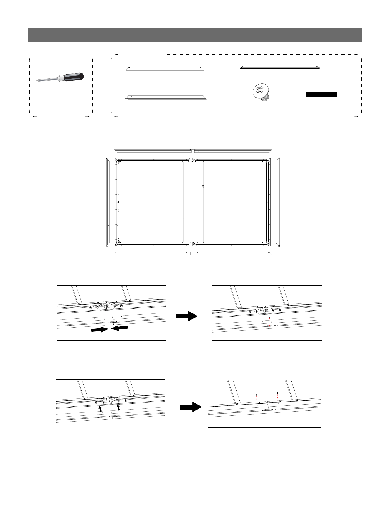
1. Lay all the sides of the outer frame as shown in the following illustration.
III. Assemble the Outer Frame
Phillips screwdriver
long side of the outer frame (A)
×
2
M4
×
6 screw(M)
×
18
(black)
Required parts
Required tool
(not included)
short side of the outer frame (C)
×
2
long side of the outer frame (B)
×
2
2. Connect the long side of the outer frame (A) and the long side of the outer frame (B).
3. Connect the long side of the outer frame and the inner frame with M4
×
6 screws(M).
B A
C
B
A
C
M M
Velcro(P)
×
2
M
8
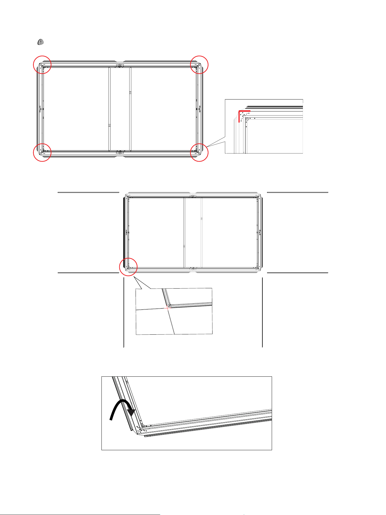
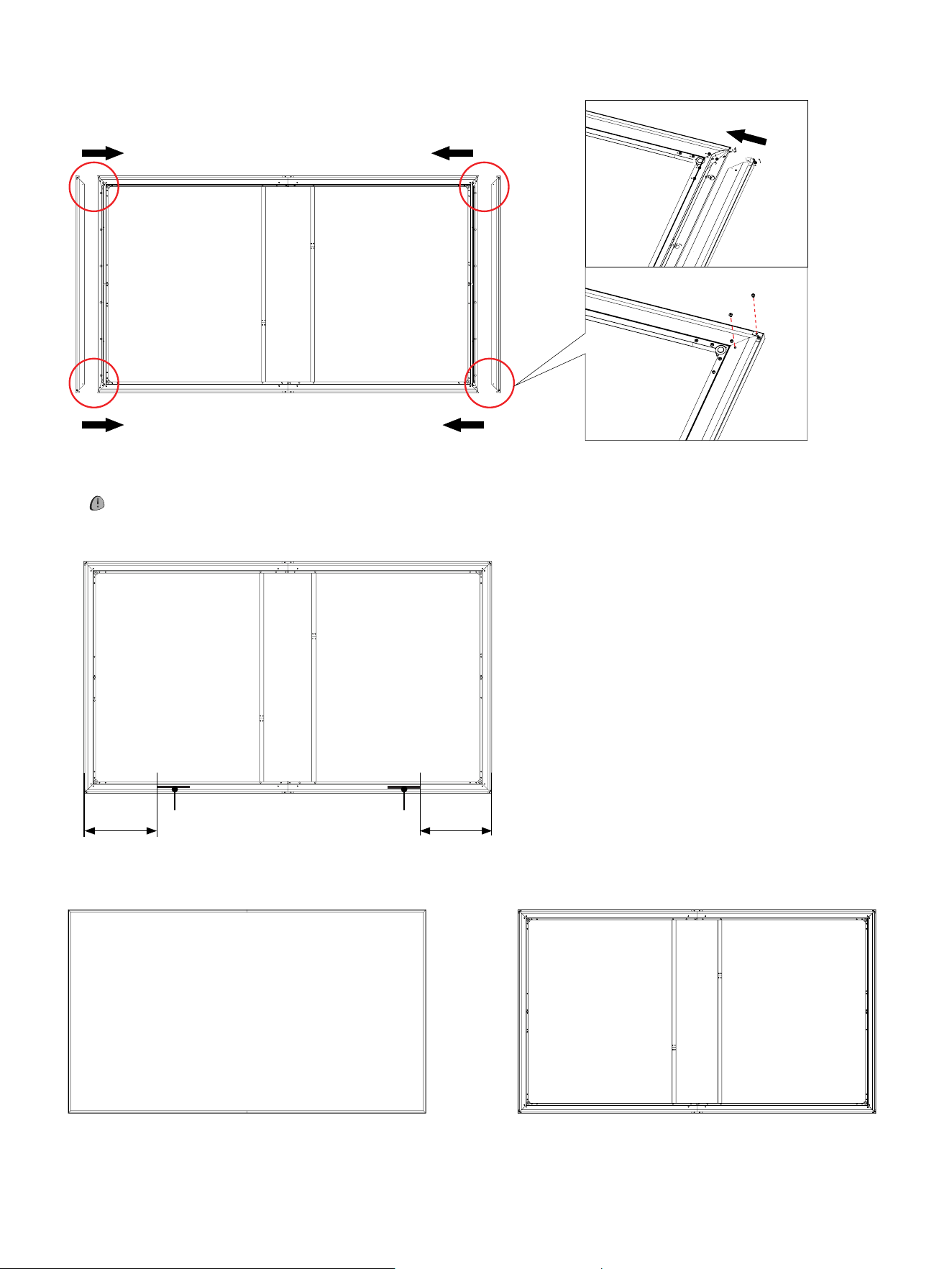
4. Connect the short side of the outer frame and the inner frame with M4×6 screws(M). Adjust the gaps on the four corners of
the outer frame.
Congratulations,the screen assembly is finished. The frontal and back sides of the screen is shown as below.
Frontal side
Back side
Bottom
5. Tear off the release paper on one side of the Velcro(P) and attach them to the inner frame as shown in the illustration below.
NOTE: Don’t tear off the release paper on the other side of the Velcro(P) until the adjustment of the screen is finished.
Bottom
P P
M
M
150mm
(5.91inches)
150mm
(5.91inches)
9
Install the Wall Mount Bracket
WALL MOUNT BRACKET INSTALLATION
Installation Space
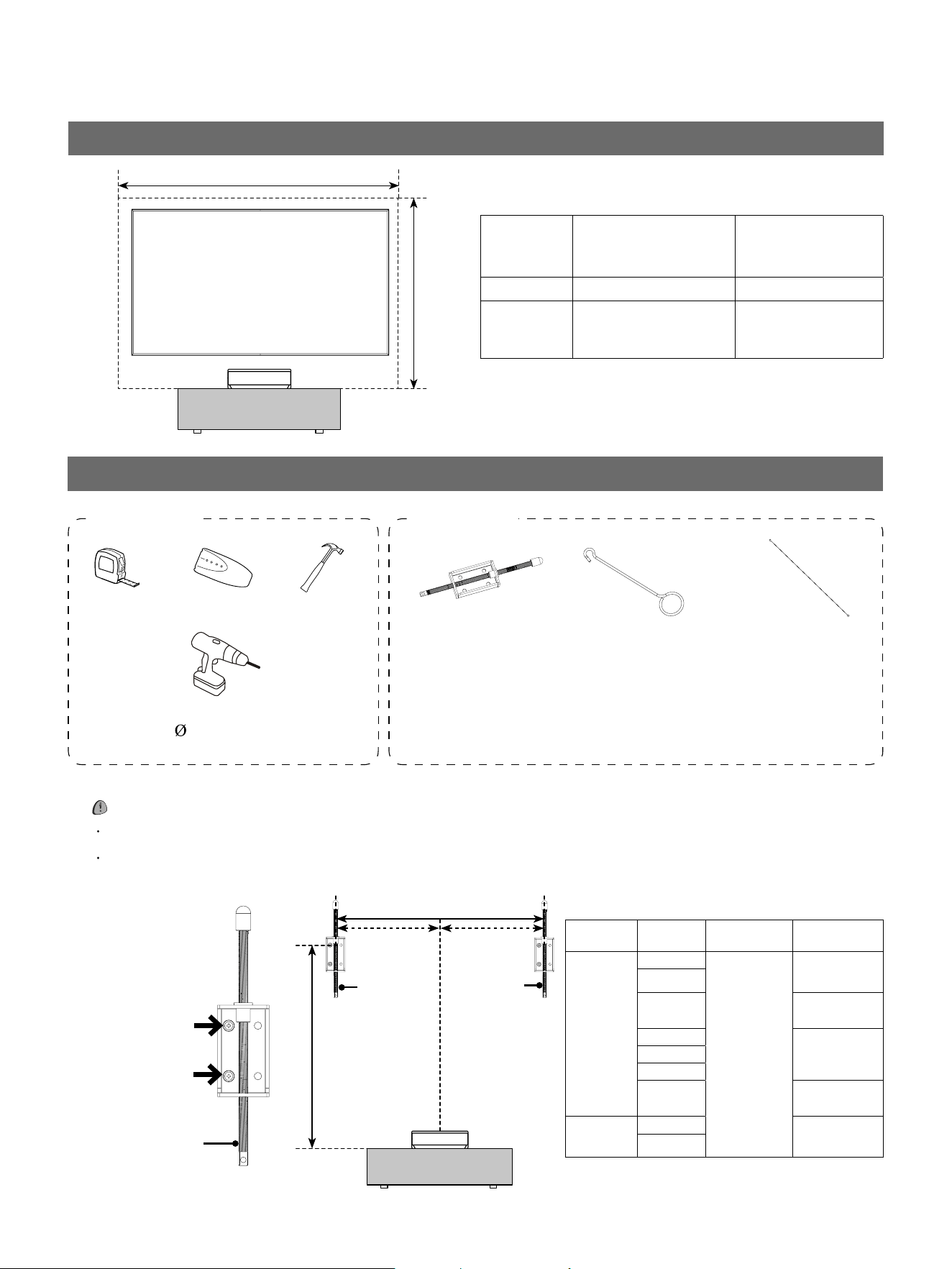
1. Mark the position of the mounting holes. Please refer to the illustration below.
NOTE:
Each bracket requires 2 screws to mount it securely to the wall.
‘a’
is the distance between the two brackets(V).
‘b’ is the distance between the first hole of the bracket and the cabinet.
Tape measure Stud nder
Hammer
wall mount bracket(V)
×
2
adjusting rod(W)
×
2
connecting rod(X)
×
2
expansion screw(Z1)
×
4
Electric drill
5/16 inch(8mm)
Required parts
A
B
Required tools
(not included)
Screen
size (inch)
Model a b
120
120L9H
1400mm
(55.12inches)
1785mm
(70.28inches)
PT1
120L5H
1813mm
(71.38inches)
120L5N
1800mm
(70.87inches)
PX3-PRO
PL2
L9Q
1769mm
(69.65inches)
110
PX3-PRO
1658mm
(65.28inches)
PL2
Fig.1
V
We recommend
using the two
screw holes as
pointed by the
arrow.
a
V
V
b
700mm
(27.56inches)
700mm
(27.56inches)
Screen size
(inch)
A (width of the wall)
B (height between
the top of cabinet to
the ceiling)
110 >102.36inches(2.6m) >77.17inches(1.96m)
120 >110.24inches(2.8m) >82.68inches(2.1m)
10
2. Secure the bracket according to the distance listed in the Fig.1. The bracket should be installed on the solid wall or the studs
of the wall.
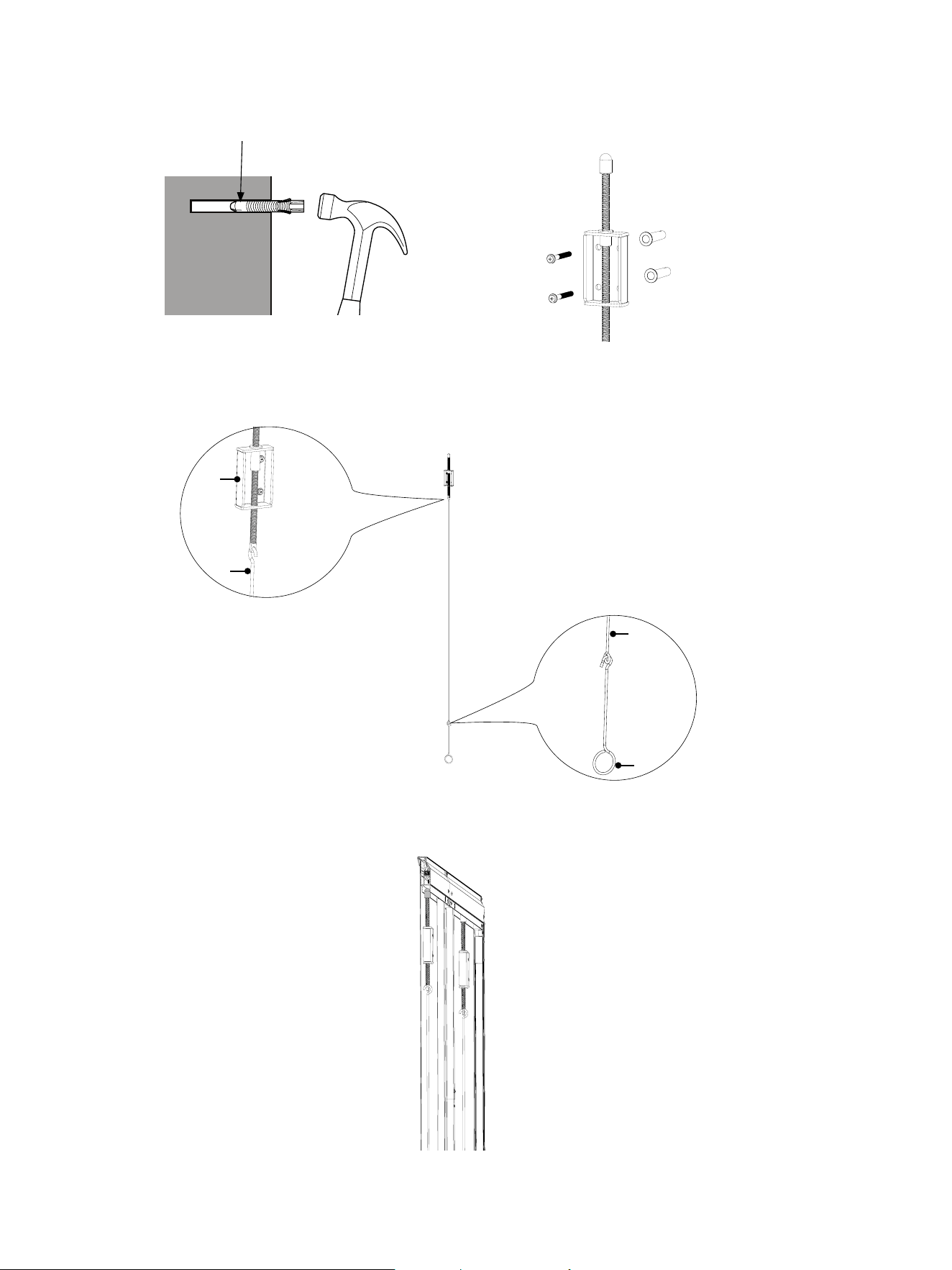
3. Hang the connection rods(X) on the mounting brackets(V), then connect the adjusting rods(W) to the connecting rods.
X
W
V
X
4. Hang the screen on the mounting brackets as shown in the illustration below.
Insert anchors
Diameter: 8mm
11
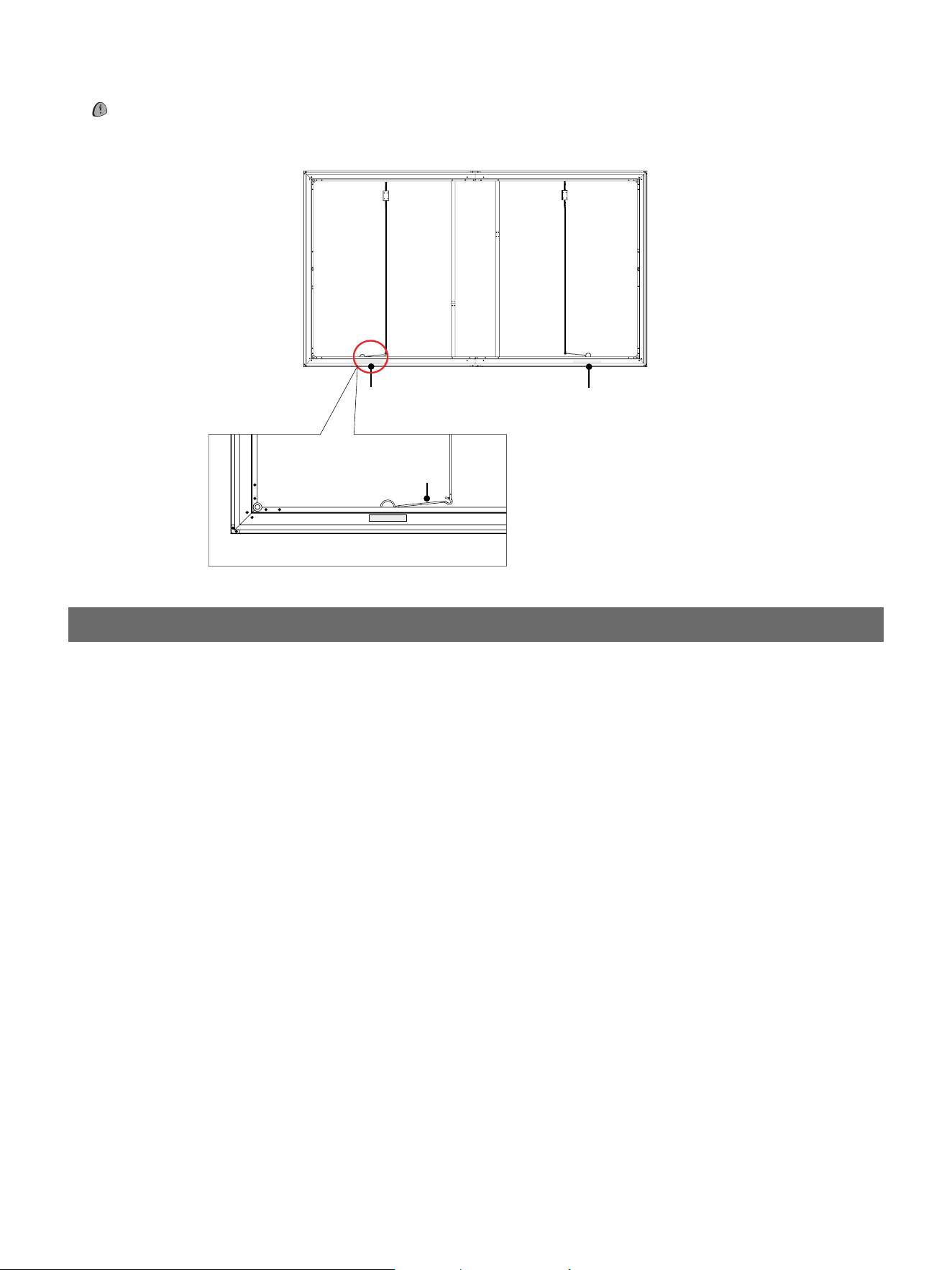
NOTE: After the screen is mounted, please do not tear off the backing paper on the Velcro(P) to attach the screen to the
wall until the alignment of the console and the screen is finished.
P
P
W
5. Fold and hide the adjusting rods(W) on the screen bracket after finishing the alignment of the console and the screen.
Maintain the Screen
1. Clean the screen surface with a soft brush or microfiber cloth with water or alcohol.
2. Do not touch the screen with hard or sharp objects, otherwise the screen may be damaged.
Quick Setup Guide
Read the guide carefully and ensure you have fully understood its contents before operating this device for the first time.
English
A
B
Paragraphs beginning with the symbol indicate important instructions, tips or conditions for the following settings.
For your own safety and the optimal performance of your device, ensure to read the safety instructions before performing any
installation.
Compatibility with 3rd party products, software and services are not guaranteed. We cannot be held liable for any damage or loss
suffered whilst operating, using or connecting to incompatible devices or apps.
The recording and playback of content on this or any other device may require permission from the owner of the copyright or other
such rights in that content. It is your responsibility to ensure that your use of this or any other device complies with applicable
copyright legislation in your country. Please refer to that legislation for more information on the relevant laws and regulations involved
or contact the owner of the rights of the content you wish to record or playback.
Read these instructions
Follow all instructions
Heed all warnings
Keep these instructions
All rights reserved.
▌Important Notice
▌Safety Instructions
To ensure safe and correct use of this product, always comply with the following precautions to avoid dangerous situations and damage to your device:
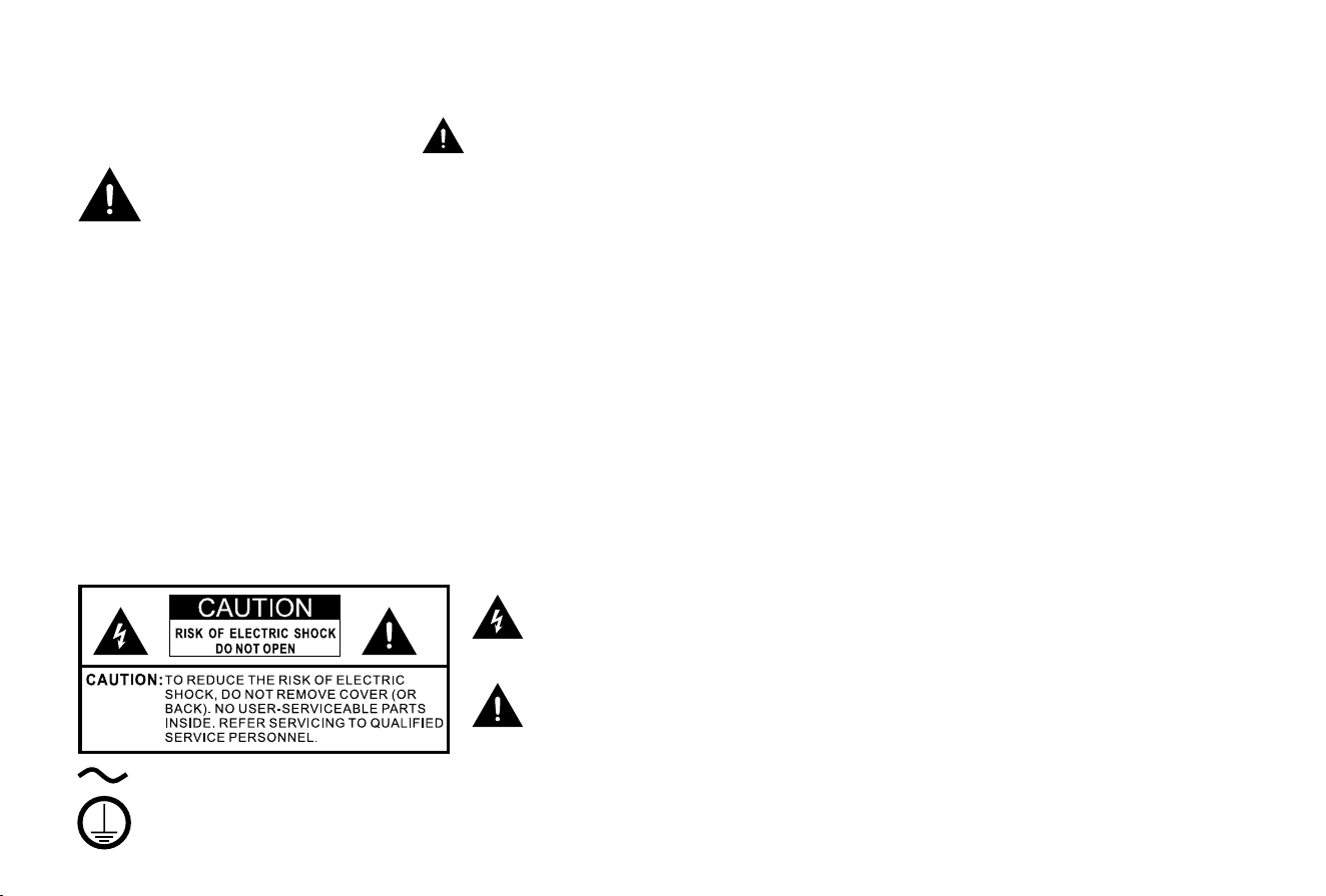
The lightning flash with arrowhead symbol, within an equilateral triangle is
intended to alert the user to the presence of uninsulated dangerous voltage
within the product's enclosure that may be of sufficient magnitude to constitute a
risk of electric shock.
The exclamation point within an equilateral triangle is intended to alert the user
to the presence of important operating and maintenance (servicing) instructions
in the literature accompanying the appliance.
AC voltage: This symbol indicates that the rated voltage marked with the symbol is AC voltage.
Class I product: This symbol indicates that it requires a safety connection of protective earthing (ground).

C
The intended use and ambient conditions
for this device
This device is intended for the rendering of video and audio signals,
on a table-top, in a home or ofce environment. It must not be used
in rooms with a high level of humidity or dust concentration. The
warranty is only valid if used as intended by the manufacturer.
WARNING
High humidity and dust concentration may lead to current leaks in
the device. To reduce the risk of re or electric shock:
- Do not expose this device to rain, moisture, dripping or splashing
water, and do not place objects lled with liquids, such as vases,
cups, etc. on or over the device.
- Do not touch the device with wet hands.
- Do not expose to direct air-conditioning and keep candles or
other naked ames away from the device at all times.
If the device is moved from a cold environment to a hot environment,
leave it switched off for at least an hour to avoid condensation. If
used outside, make sure it is protected from moisture.
If you notice anything unusual, immediately remove the power plug.
In case of re, use preferably a CO
2
gas or powder re extinguisher. If
such extinguishers are not accessible, try to isolate the electrical supply
before using a water re extinguisher.
The device may fall, causing serious personal injury or death. Many
injuries, particularly to children, can be avoided by taking simple
precautions such as:
- ALWAYS use cabinets or stands or mounting methods
recommended by the manufacturer of the device.
- ALWAYS use furniture that can safely support the device.
Power Supply
Incorrect voltages can damage the device. Only connect this device
to a power supply with the correct voltage and frequency noted on
the type plate, using the supplied power cable.
The power plug must be easily accessible so that the device can be
disconnected at all time. The device is live, even if in standby mode,
as long as the device is connected to a power outlet.
It is recommended that this device is placed on a dedicated circuit.
- Do not overload the power outlets by connect too many
appliances to the same outlet. Overloaded wall outlets, extension
cords, etc. are dangerous and can result in electric shock and re.
After power off, don't turn it on again in 5 seconds. Frequent
- ALWAYS ensure the device is not overhanging the edge of the
supporting furniture.
- ALWAYS educate children about the dangers of climbing on
furniture to reach the device or its controls.
- ALWAYS route cords and cables connected to your device so they
cannot be tripped over, pulled or grabbed.
- NEVER place the device in an unstable location.
- NEVER place the device on tall furniture (for example, cupboards
or bookcases) without anchoring both the furniture and device to
a suitable support.
- NEVER place the device on cloth or other materials that may be
located between the device and supporting furniture.
- NEVER place items that might tempt children to climb, such as
toys and remote controls, on the top of the device or furniture on
which the device is placed.
If your existing device is being retained and relocated, the same
considerations as above should be applied.

D
switching power supply in a short period of time can cause abnormal
device.
The apparatus shall be connected to a MAINS socket outlet with
a protective earthing connection.
Power plug and power cable
- Do not touch the power plug with wet hands.
- Do not place heavy objects on the power cable. Route the cable
so that it is not kinked or laid over sharp edges, walked on or
exposed to chemicals. A power cable with damaged insulation
can cause electric shock and re.
-
Pull the power plug, NOT on the cable when disconnecting. The
cable can become damaged and cause a short circuit if pulled on.
- Do not place the power cable near a high temperature object.
- Do not move the device with the power cable plugged into a
socket.
- Do not use a damaged or loose power cable, or a damaged
socket outlet.
- Do not use any power cords other than the one supplied with this
device.
-
MAIN plug on the power cord is used as the disconnect device,
the disconnect device and socket-outlet shall be easily accessible.
Air ventilation and high temperatures
Install your device only where there is proper ventilation, and ensure
that there is at least 30 cm free space on the sides and 10 cm
free space on the back unit for air circulation. Excessive heat and
obstruction of ventilation could lead to re or early failure of some
electric components.
- Do not block any ventilation openings with newspapers,
tablecloths, curtains, etc.
- Do not dry clothing etc. on top of the device.
- Take care not to touch the ventilation openings since they may
become hot.
- Do not insert foreign objects into the device through the vents.
Warning about off-gassing
New furniture, carpet, paint, building materials and electronics can
release chemicals into the air through evaporation. After you set your
device up and turn it on for the rst time, you may notice a slight
smell within a couple of hours. This is because some components
of device are heating up for the rst time. The materials that we use
fully meet the environmental requirements and regulations. Your
device is working just ne and the fumes from the off-gassing will
diminish eventually.
Supervision
- Do not let children play unsupervised close to the device. It could
tip over, be pushed off or pulled down from the stand surface
and injure someone.
- Do not allow a switched-on device to run unattended.
Volume
Loud music and noise may lead to irreparable damage to your ears.
Extreme volumes should be avoided, especially during long-term
exposure and when using headphones.
If you hear a drumming noise in your ears, turn down the volume or
temporarily stop using headphones.

E
Thunder Storms
Pull out the power plug and all connected antenna cables from the
device during a thunderstorm. Overvoltage caused by lightning
strikes can damage the device via the antenna system, as well as
the wall socket.
Long periods of absence
As long as the power plug is connected to a live socket outlet, the
device will consume power even in standby mode. The power plug
and all connected antenna cables should be disconnected during
long periods of absence.
Cleaning and care
CAUTION:
Unplug the power cord prior to cleaning the device.
Clean the device, the screen, and the remote control with a soft,
moist, clean and colour-natural cloth only. Do not use any chemicals.
- Do not subject the surfaces to insect repellent, solvent, thinner or
other volatile substances. This may degrade the surface quality.
- Do not spray water or other liquids directly on the device. Liquid
inside the device could lead to product failure.
- Also wipe the power plug with a dry cloth at regular intervals.
Service/Repair
Never remove the cover/back of the device; there are no user
serviceable parts inside. Refer all service to qualied service personnel.
Packaging
Keep the anti-moisture materials and plastic bags out of reach of
children.
Plastic bags can cause suffocation and the anti-moisture material is
harmful if swallowed. If swallowed by mistake, force the patient to
vomit and visit the nearest hospital.
Modication
Do not attempt to modify this product in any way. Unauthorized
modication could void the warranty of this device, cause electric
shock and re.
Remote Control batteries
- Do not disassemble the product or attempt to remove the battery
by yourself.
- Do not dispose it into re.
- Do not crush or puncture the battery.
- Prevent it from falling down.
- Use the correct charging device.
- Be sure to dispose of battery correctly.
- Do not expose battery to excessive heat such as sunshine, re or
the like.

F
Outdoor Antenna Grounding
If an outdoor antenna used, be sure the antenna system is protected
against voltage surges and built-up static charges.
Disposal
Refer to the recycling section of this guide.
Laser
Do not look directly at the lens when this device is on because
the laser light may damage your eyes!
- This product comes with a laser module. Do not tear or modify this
device in any manner; otherwise, it may result in personal injury.
RG2
As with any bright light source, DO NOT STARE INTO THE
BEAM IEC 62471-5: 2015
CLASS 1 LASER PRODUCT
λ = 459-471nm/519-531nm/635-651nm
Wavelength 459-471nm/519-531nm/635-651nm
CLASS 1 LASER PRODUCT IEC 60825-1: 2014
CAUTION:
Use of controls or adjustments or performance of procedures
other than those specied herein may result in hazardous
radiation exposure.
- If this device requires a repair, please wear laser eye protection
with an optical density OD that is 4 or higher and has a wave
length of 459-651nm.
- Do not place any water-containing vessel on this device, such
as cosmetics or liquid medicine.
- If any object or water enters this device, please unplug this
device and contact the service staff of Hisense.
- Do not place any exposed re source (e.g. burning candle) on
this device. Keep away from high temperature and heat.
- Do not expose the battery to direct sunlight or candle light.
- Keep air vents on both sides clear from any objects to prevent
the device from overheating inside.
- To avoid a short circuit, product damage or electric shock, do
not use any sharp object or metal to touch the ports or other
openings on the device.
- If this device has been in a warm environment, allow any built-
up condensation to evaporate rst BEFORE you switch the
device on.
- Do not allow a child to stand on or climb up this device.
- Do not place any object above or in front of the lens because the
laser light could cause the object to become ammable.
- Clean the lens periodically with a clean cloth and make sure
the device is turned off before you start.

1
Table of Contents
Accessories List 1
Laser TV Diagram 2
STEP 1. Mount the Screen 2
STEP 2. Install the Laser TV 2
STEP 3. Align the Projected Image 7
STEP 4. Use Your Remote 9
STEP 5. Proceed with the Screen Setup Menu 11
Maintenance & Troubleshooting 12
Product Specications 14
Recycling / Licenses 15
Congratulations on the purchase of your new Laser TV! This Guide will walk you through a few easy steps to set up
your Laser TV.
Please visit Hisense ofcial website for more details.
Figures and illustrations are provided for reference only and may differ from actual product appearance.
Parts of the software function change with the system upgrade.
NOTE: The accessories list above may vary depending on
specic model, country or region. Please refer to the actual
accessory bag.
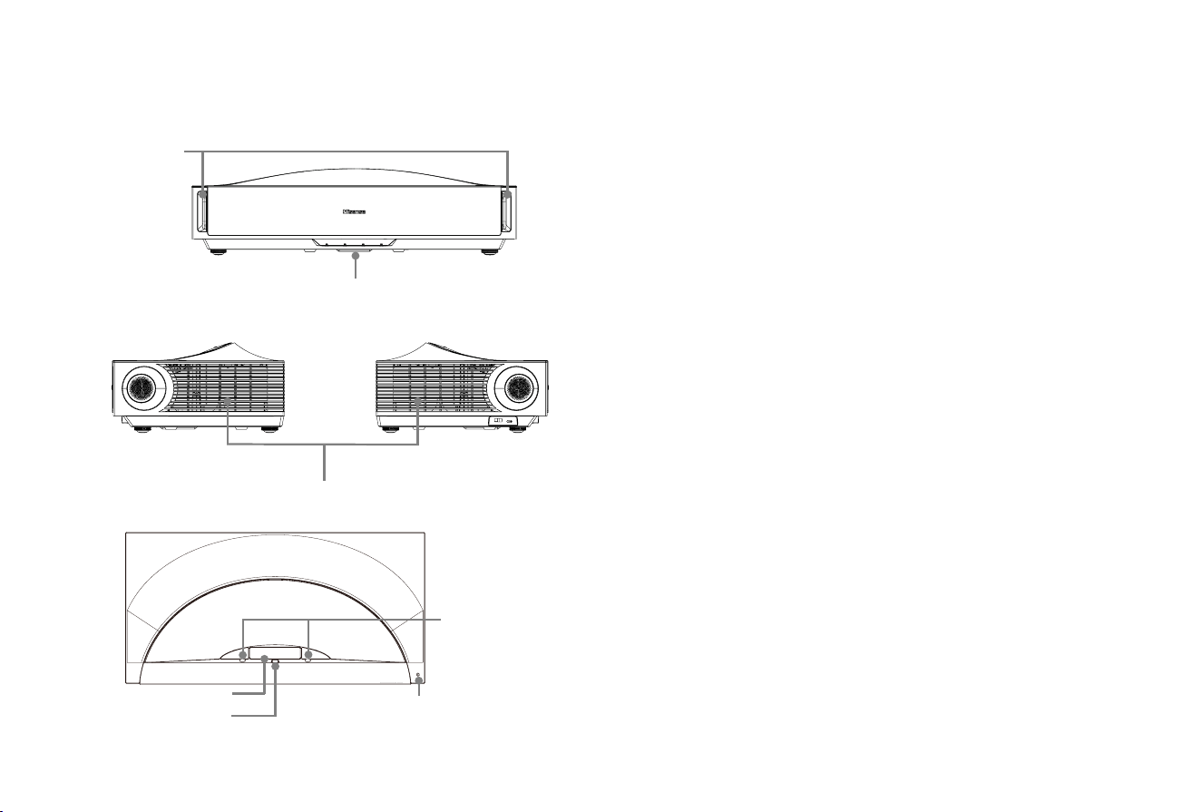
Accessories List
• Laser TV × 1
• Remote control × 1
• Gloves for handling the Laser TV × 2
• Power cord × 1
• Laser TV Quick Setup Guide × 1
• Laser TV Warranty Card × 1
• Cleaning kit for the lens × 1
• C-shape blocks × 2
• C-shaped Block Installing Instruction × 1
2
Laser TV Diagram STEP 1 Mount the Screen
If you have purchased a screen, then refer to the specific screen
installation guide.
STEP 2 Install the Laser TV
Be sure to protect the lens when you handle this device.
We recommend to connect all cables to the ports on the back
of the Laser TV before positioning the Laser TV. (Audio, video,
Ethernet cables and external devices are not included in the
accessory bag.)
Check to ensure that you have selected the right cables for the
ports and that they are connected securely. Loose connections
may affect the quality of the picture image and colour.
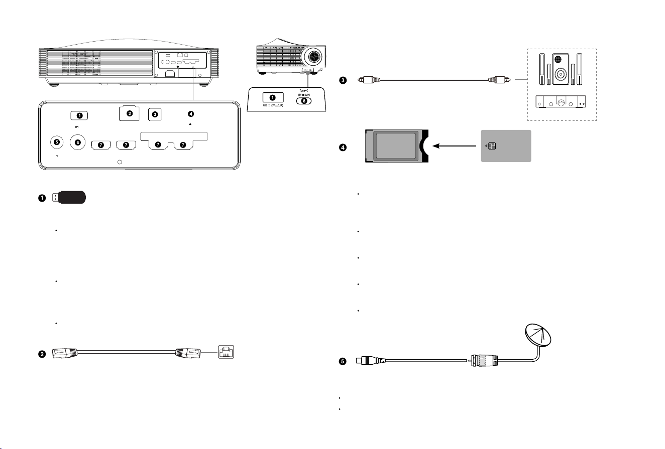
Power indicator
Remote control receiver
Eye protection sensor
Power button
Foreign Object Detect
Lens with laser
Air vents
3
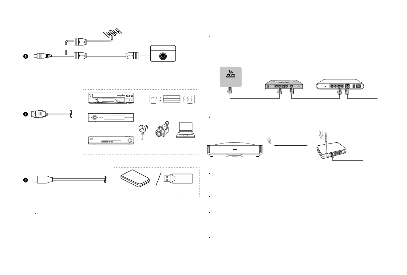
NOTE:
When connecting a hard disk or a USB hub, always connect
the mains adapter of the connected device to the power supply.
Exceeding a total current consumption may result in damage. The
maximum current consumption of the USB 2.0 device is 500mA and
the maximum current consumption of the USB 3.0 device is 1A.
For non-standard and large-capacity individual mobile hard disks,
if the pulse current is larger than or equal to 1A, it may cause
the device to restart or self-lock. The Laser TV is therefore not
compatible with this type of drive.
The voltage output of the USB is 5V.
Ethernet (a router for Internet connection is needed)
Satellite antenna
(not included)
NOTE:
ANT1 Jack can provide power for satellite antenna (13/18V, 0.5A max.)
DVB-S/S2 may not be applicable in some models/countries/regions.
External audio devices
Audio Amplier
Speakers
Digital audio adapter
USB 1
DC 5V 1A(MAX)
LAN
DIGITAL
AUDIO OUT
COMMON INTERFACE
[ CARD FACE FRONT ]
ANT 1 DVB-S/S2
13/18V 0.5A
ANT 2
DVB-T/T2/C
HDMI 1
Ultra High-Speed
HDMI 2
Ultra High-Speed
HDMI 3 (eARC)
4K@60Hz
HDMI 4
4K@60Hz
SMART CARD
CAM CARD
NOTE:
Before you insert/remove the CI+ module, ensure that the Laser
TV is switched off. Then insert the CI card into the CI+ module in
accordance with the service provider’s instructions.
Do not repeatedly insert or remove the Common Access Module
as this may damage the interface and cause a malfunction.
You must obtain a CI+ module and card from the service
provider of the channels you want to watch.
Insert the CI+ module with the SmartCard in the direction
marked on the module and SmartCard.
CI+ is not supported in some countries and regions; check with
your authorised dealer.
4
LAN (
Wired setup
)
To connect your Laser TV to the network, connect the LAN port on
the back of your Laser TV to an external modem or router using a
LAN (Ethernet/Cat 5) cable. See the illustration below.
Wireless setup
To connect your Laser TV to your network wirelessly, you need a
wireless router or modem. See the illustration below.
NOTE:
You must use the built-in Wireless LAN Adapter to use a wireless
network because the set doesn't support external USB network
adapters.
If the wireless router supports DHCP, your Laser TV can connect more
easily to the wireless network.
If you apply a security system other than the systems listed below, it
will not work with the Laser TV.
Security system: WPA, WEP, WPA2, WPA3.
In order to guarantee smooth network, the distance between router
and Laser TV should be less than 10 metres.
LAN Cable
Laser TV PORT
Modem CableLAN CableLAN Cable
External Modem
(ADSL / VDSL / Cable TV)
IP Sharer (Router)
(with DHCP server)
LAN
Wireless router with DHCP
Wireless LAN Adapter
built-in Laser TV
HDMI
External AV devices
VCR DVD Player
Set-top Box
Satellite Receiver
Laptop
Video
Camera
Outdoor
Antenna
Antenna Cable (75Ω)
or
ANT OUT
Cable
VHF/UHF Antenna
NOTE:
The Type-C port can connect to a Type-C USB drive or connect
to a USB 3.0 drive via a Type-C dock, but does not support DP
(DisplayPort) display.
Mobile Hard Disk
USB Flash Drive
5
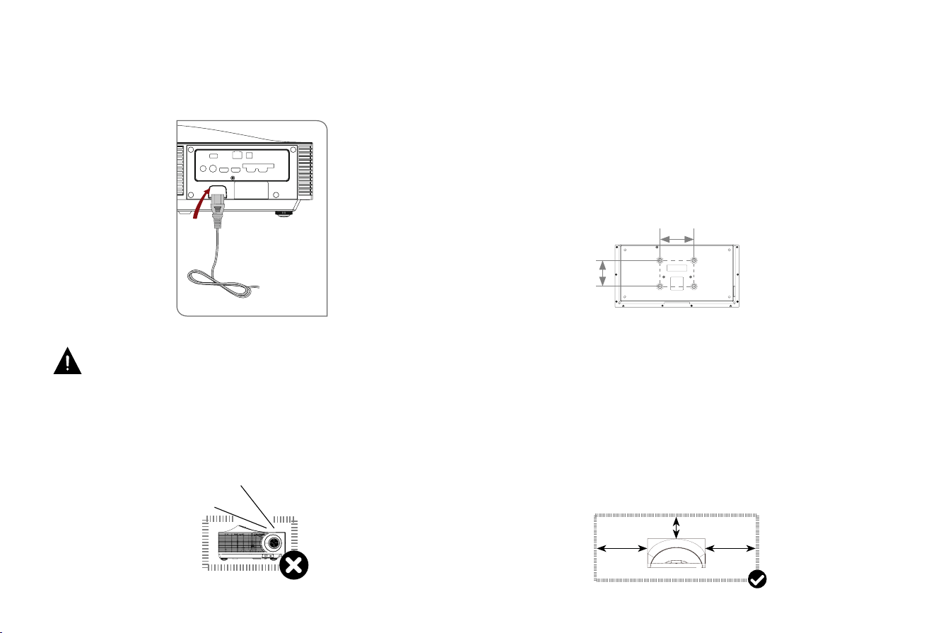
Plug the power cord into a power socket.
Press the POWER button to switch on the device.
WARNING: Poor ventilation will cause the device to
overheat or become damaged.
• Do not block the ventilation openings or place any object on
the device.
• Do not place the device in any narrow, enclosed or poorly
ventilated space.
Laser beam
Power Cord
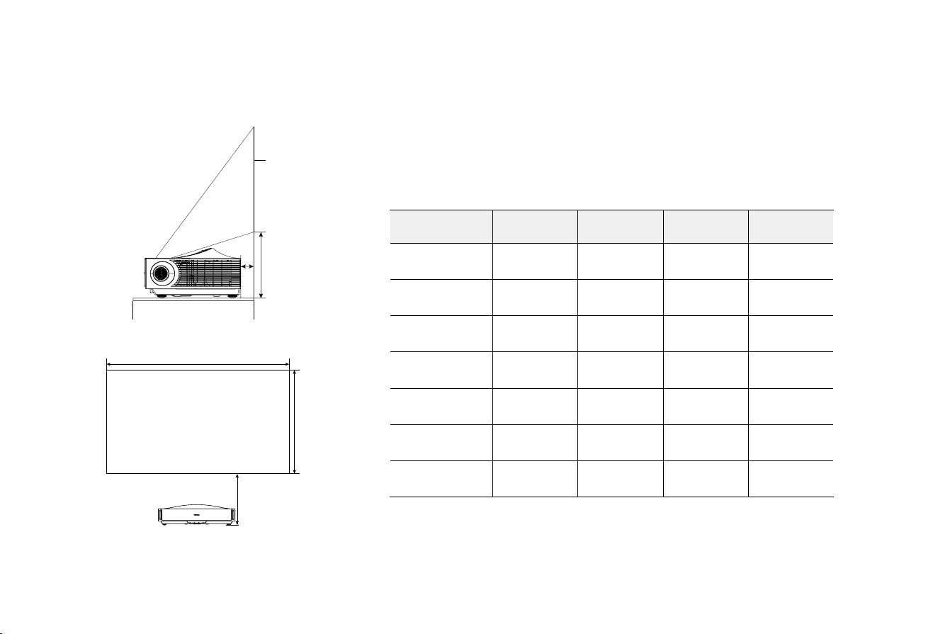
To ensure proper ventilation of the device, the minimum space
must be maintained as shown in the diagram below.
Ceiling installation
The device can be installed on the ceiling through the four
threaded holes on the bottom of the device.
Please use a certied ceiling mount for the installation and
ensure that four certied bolts of 6M×10mm are used to secure
the device to the mount.
Select a suitable ceiling mount based on the weight of the
device and the pattern of the mounting holes on the bottom of
the device, as shown below.
Only qualied professionals should perform the installation.
Using defective mounts or bolts, or improper installation, can
result in personal injury or property damage.
The user shall assume full legal and nancial responsibility for
any personal injury, property damage, or consequential losses
arising from:
• Use of non-certied installation materials
• Improper installation practices deviating from specications
• Failure to implement safety measures
30 cm
30 cm
10 cm
6.7 inches
(170 mm)
5.1 inches
(130 mm)
6
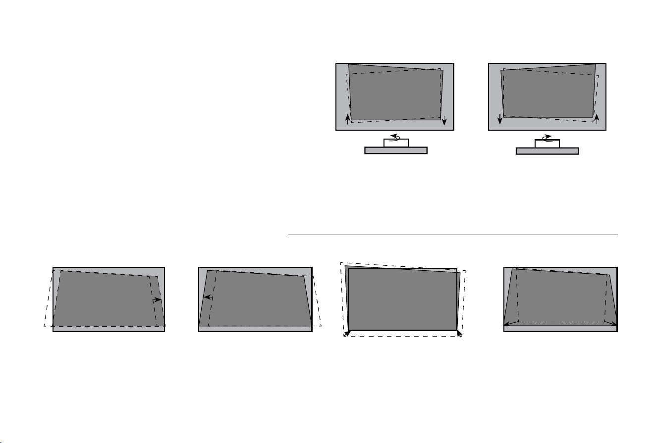
Image size and projection distance
NOTE: The sizes of the projected image for each projection distance may differ depending on the actual installation environment.
X
Y
B
B
A
Projected Image
Projected Image
Size (inch)
X(mm) Y(mm) A(mm) B(mm)
80 1770 996 57 298
100 2215 1245 137 354
110 2436 1369 176 382
120 2657 1494 216 410
139 3076 1730 292 463
150 3320 1867 336 494
200 4427 2492 535 634
7
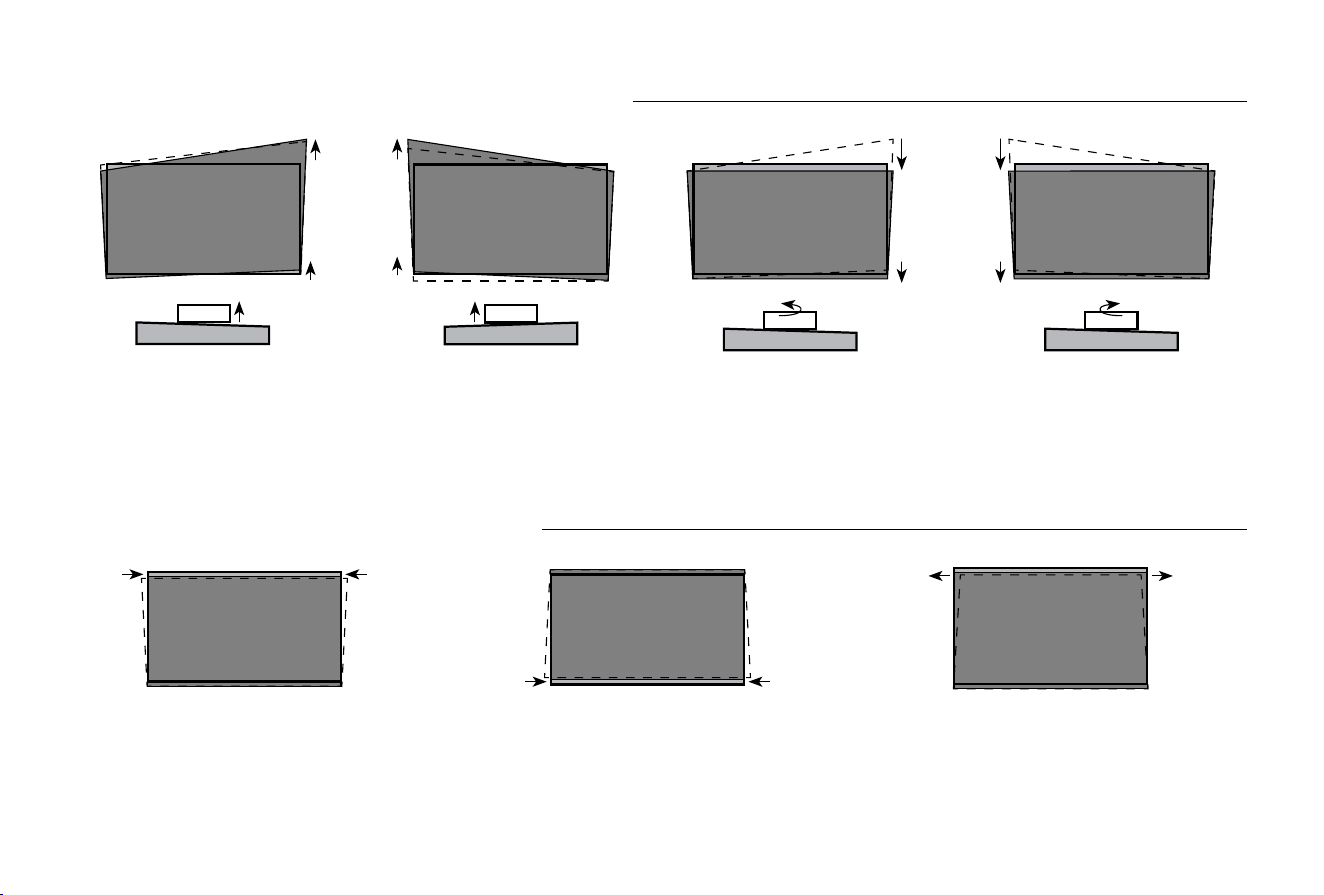
• Follow the steps below, only if they apply to your situation.
• Adjust the height of the screen until the projected image is
parallel with the screen.
• Rotate the feet with an overlooking view, and do not look
directly at the lens when the console is on because the laser
light may damage your eyes.
STEP 3 Align the Projected Image
If the bottom of the image is lower on the left (right) and higher
on the right (left), rotate the console counterclockwise (clockwise)
until the bottom of the image is parallel with the screen.
PARALLEL THE BOTTOM OF THE IMAGE WITH THE SCREEN
FIT THE BOTTOM OF THE IMAGE TO THE SCREEN
Move the console to the right Move the console to the left Move the console closer to the
screen
Move the console farther from
the screen
8
ADJUST THE UPPER-RIGHT/UPPER-LEFT OF THE IMAGE
FILL THE TOP OF THE IMAGE TO THE SCREEN
Rotate the console
counterclockwise until the
bottom of the image is parallel
to the screen
Rotate the console clockwise
until the bottom of the image is
parallel to the screen
Rotate the front-right foot
clockwise
Rotate the front-left foot
clockwise
Rotate the front-left and front-right feet
clockwise
Rotate the back-left and back-right feet
clockwise
Rotate the front feet counterclockwise
if the back feet are already at their
maximum height
9
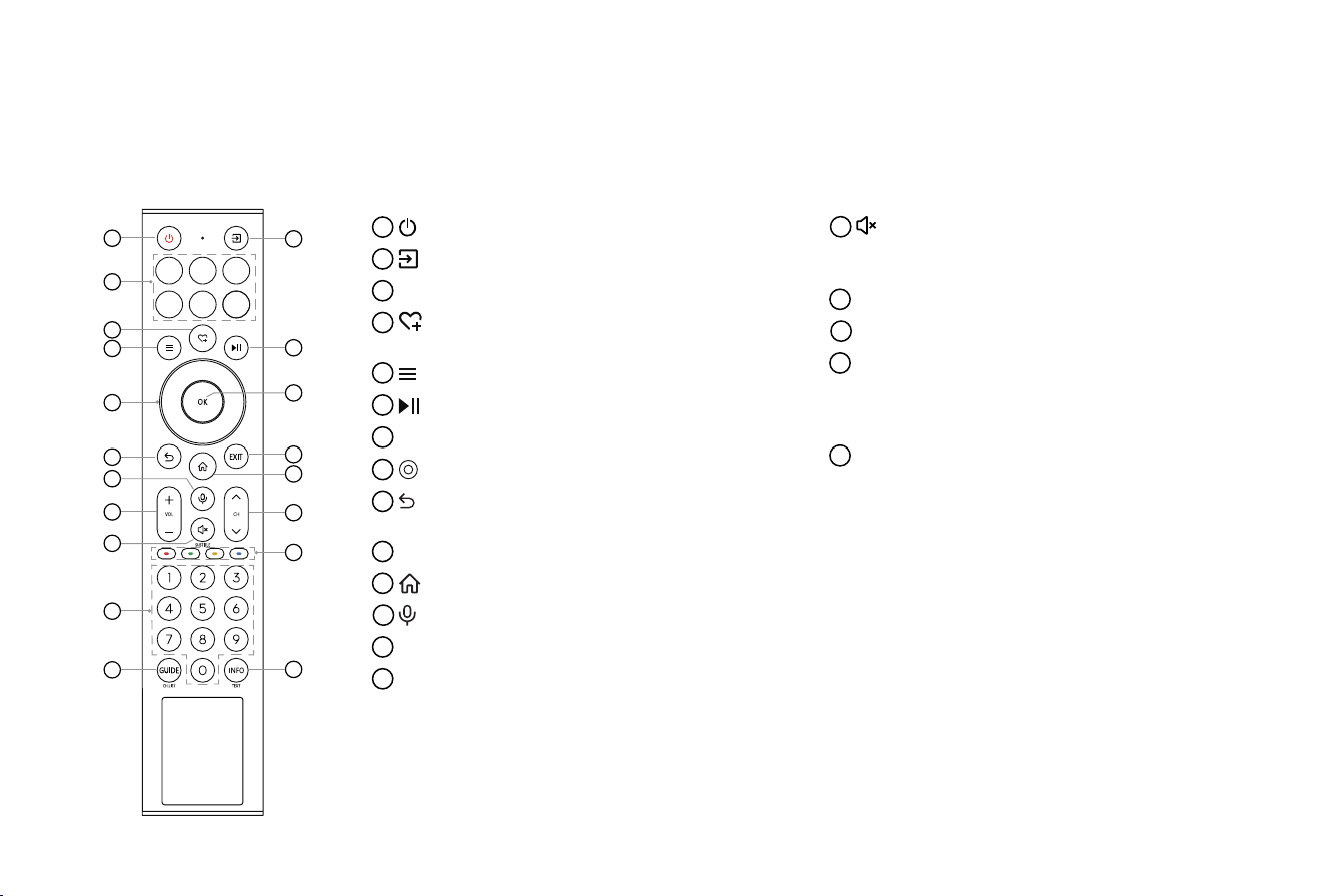
STEP 4 Use Your Remote
1
: Power on/Standby
2
: Input source selection
3
APP: Quick access to APPs
4
: Custom button, provides quick access to its
user-dened function
5
: Press to enter Menu
6
: Playpad keys
7
OK: Confirm selection
8
: D-pad (up/down/left/right navigation buttons)
9
: Under the Menu or App, return to the
previous place
10
EXIT: Exit the menu or exit the application
11
: Display the Home screen
12
: Activate the microphone
13
VOL: Volume (up/down)
14
CH: Channel (up/down)
1
3
6
7
5
9
10
11
12
13
15
16
18
14
17
15
: Mute and restore sound (Long press to be
used as SUBTITLE: Activate or deactivate the
subtitle mode)
16
Four colour buttons: Special function buttons
17
Number buttons: Select a channel or input numbers
18
GUIDE: Display the Electronic Program Guide (DTV
mode)
(Long press to be used as CH.LIST: Display the
Channel List)
19
INFO: Display the current program information
(Long press to be used as TEXT: Turn on/off the
teletext function)
NOTE: The included remote control will vary depending on models, countries/regions. Check information ac-
cording to the actual remote control in the accessory bag.
2
4
8
19
BUTTONS ON YOUR LASER TV REMOTE
NOTE: The labels on the buttons are provided for reference only. The actual appearance of the remote packaged with the Laser TV
may differ from this diagram.
10
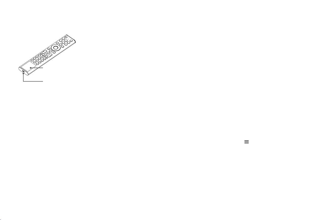
CHARGING THE REMOTE CONTROL
You can charge the remote by
exposing the solar cell to light or
using a USB type-C cable (not
provided).
When charged by type-C port, the
red indicator will blink. When fully
charged, the indicator will stop
blinking first and then turn off.
solar cell
type-C port
(5V,
≥
500mA)
NOTE:
• Figures and illustrations are provided for reference only and
may differ from actual product appearance.
• The battery is not user-replaceable. Do not try to remove or
change the internal battery yourself, as it may cause damage to
the battery/device, personal injury, re or explosion.
• When you do not use the remote control, place it face up to
make the solar cell expose to light.
• Exposing the battery to environments with extremely high
temperatures can result in explosion or the leakage of
ammable liquid or gas.
• Battery chemicals can cause skin irritation. If chemicals come
into contact with your skin, wash immediately.
• Disposal of a battery into re or a hot oven, or mechanically
crushing or cutting of a battery, that can result in an explosion.
• Always handle the remote control with care to prevent it from
falling down.
REMOTE CONTROL RANGE INFORMATION
• The remote control can work up to 8 metres in front of the Laser
TV. (This distance is used for an unpaired infrared device.)
• Remote control angle: with the remote sensor as the highest
point and 6 metres away, the horizontal control angle is within
±30°, while the vertical angle is within ±15°. (This distance is
used for an unpaired infrared device.)
PAIRING THE REMOTE CONTROL (ONLY FOR BLUETOOTH
REMOTE CONTROL)
Pair the remote to the Laser TV after the device is switched on.
Keep the remote control within 3 metres from the Laser TV and
press any button (except power and mic button) to pair.
NOTE:
• In special cases, press and hold [ ] button to pair.
• If an unknown error occurs with the remote control, it would
be caused by interference. Try to eliminate the cause of the
interference and pair it again.
• If an unknown error occurs with the remote control, please
recharge and activate the remote control.
• The remote cannot be paired to the Laser TV while the Laser
TV is in standby mode.
• A battery subjected to extremely low air pressure that may result
in an explosion or the leakage of ammable liquid or gas.
11
STEP 5 Proceed with the Screen Setup Menu
PROJECTION MODE
If you need to ip the image over top-to-bottom and/or left-to-
right, select the Projection Mode.
NOTE:
• Obstacles between the console and the screen, foreign
objects on the screen surface, dark-colored walls, and strong
ambient lighting may interfere with the automatic screen
alignment. Ensure all obstacles and foreign objects are
removed, use a lighter-colored wall, and minimize ambient
light before initiating automatic screen alignment.
• This function is available only for screen of 100" and 120".
• Since screen type signicantly impacts the performance of
auto screen correction, we strongly recommend using the
Hisense Ambient-Resisting Screen for optimal results.
• Manual correction may be required for ne-tuning if auto
correction is unsatisfactory.
AUTO GEOMETRIC CORRECTION
1. Adjust the Laser TV position by using the levelling feet as
needed, and ensure the frame of the screen is located inside
the rectangular border.
2. Click Next to continue.
3. An auto-correction pattern will be displayed below, and the
correction process will complete automatically.
4. If the auto-correction results are unsatisfactory, use manual
correction for ne-tuning.
MANUAL GEOMETRIC CORRECTION
Select points and move it to t the projected image into the
screen.
1. Press
/ / < / > buttons on your remote control to move
focus, and press OK button to choose a point you need to
adjust.
2. Long press
/ / < / > buttons: quick adjustment of the
projected image;
Short press
/ / < / > buttons: precise adjustment of the
projected image.
3. Press button to save your adjustment, and you can select
other points to adjust the image.

12
Maintenance
• Avoid touching the device when it is running or immediately
after it is turned off, as it may be hot.
• Do not clean the device with oil-based products as they
can deteriorate the exterior or damage the paint. Extended
contact with rubber or ethylene products can cause stains on
the device.
• If the exterior of the Laser TV becomes dirty, turn off the
device and wipe it with a damp, soft cloth.
• Lens Care:
◦ Avoid touching the lens with your hands.
◦ Do not use ordinary cleaning cloths to wipe the lens.
Troubleshooting
If you are having trouble with your device, rst try turning it off
and on again. If this does not x the problem, check the tips in
the following.
It takes a few seconds before the picture is displayed after
the device is switched on. Is this normal?
Yes, this is normal. The Laser TV is in the process of initialisation
and searching for information on previous settings.
No sound or no picture
1. Check if the power cord is plugged into a working mains socket.
2. Press the Power button on the remote control to activate
the device from 'Standby' mode.
3. Check if the power indicator is lit or not. If it is, then the Laser
TV is powered.
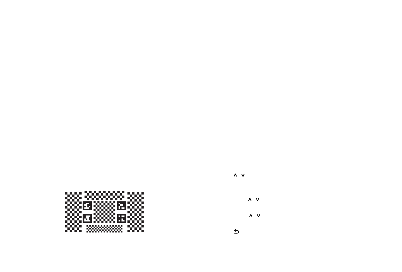
FOCUS ADJUSTMENT
You can adjust the focus parameters by pressing the up and
down buttons on the remote. The focus effect is adjusted in real
time according to the displayed background image card.
EYE PROTECTION
In order to protect your eyes, turn the Eye Protection on, and
do not look into the lens. If you get too close to the Laser TV, the
light output will be temporarily disabled after 5 seconds.
If you want to return the image position to the factory default,
select Reset on the screen.
◦ Use a dust blower to remove dust from the lens.
◦ For grease, dirt, and ngerprints, have a professional clean
the lens using optical cleaning cloths, lens wiping paper,
or professional cleaning solutions to avoid damaging the
optical coating and affecting image quality.
• Always use the Power button on the remote control to turn off
the device. Do not cut off the power directly while the device
is operating.

13
No picture and/or sound after connection to an external
source
1. Check if the output connection of the external source and the
input connection of the Laser TV are correct.
2. Make sure you have made the correct selection for the input
mode of the incoming signal.
Picture is normal but there is no sound
1. Check the volume settings.
2. Check if 'Mute' mode is activated.
Sound is normal but there is no picture or only a black and
white picture
1. If the picture is black and white, unplug the device from the
power socket and re-plug it after 60 seconds.
2. Check if the Colour Saturation is set to 50 or higher.
3. Try different sources.
Sound and/or Picture are distorted or appear wavy
1. An electric appliance may be affecting the Laser TV. Turn
off any appliances nearby and move it farther away from the
Laser TV.
2. Insert the power plug of the Laser TV into another power
socket.
Sound and/or Picutre are blurry or cut out
1. Check the direction, position and connection of the antenna if
an external antenna is used.
2. Adjust the direction of the antenna or reset or ne tune the
channel.
The plastic housing is emitting a clicking sound
Temperature changes during operation may cause the device
to slightly expand or shrink, which may cause a clicking sound.
This is normal and the device is in perfect working order.
The remote control does not work
1. Ensure that the device is connected to the mains socket and
can be operated.
2. Please recharge and activate the remote control.
14
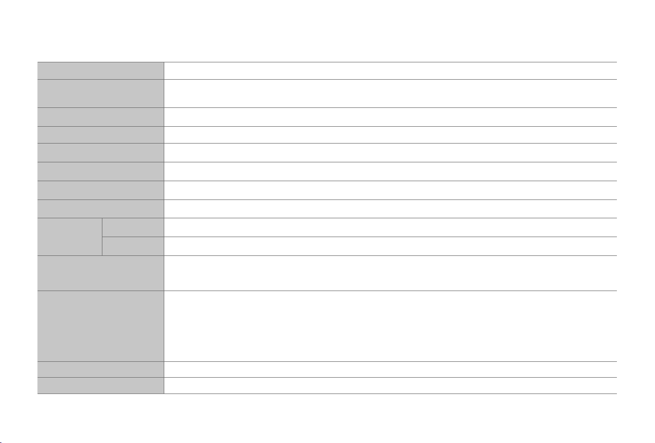
Product Specifications
Disclaimer: All products, product specications, and data are subject to change without notice to improve reliability, function, design or otherwise.
Model Name Laser TV
Dimension (L × D × H)
24.6 × 12.5 × 6.5 inches
(624 × 317 × 166 mm)
Weight 28.4 lbs (12.9 kg)
Active Screen Size (Diagonal) 80 ~ 200 inches
Screen resolution 3840 × 2160
Audio power 2 × 15 W + 2 × 15 W + 2 × 10 W + 2 × 8 W + 2 × 10 W
Power consumption 350 W
Power supply 120-240V ~ 50/60Hz
Receiving
systems
Analog PAL-D/K, B/G, I, SECAM-D/K, B/G
Digital DVB-T/T2, DVB-C, DVB-S/S2
Environmental conditions
Temperature: 41°F - 104°F (5°C - 40°C)
Humidity: 20% - 80% RH
Atmospheric pressure: 86 kPa - 106 kPa
HDMI Input
RGB / 60Hz (640×480, 800×600, 1024×768)
YUV / 60Hz (480i, 480p, 720p, 1080i, 1080p)
YUV / 50Hz (576i, 720p, 1080i, 1080p)
3840×2160 / 24Hz
,
3840×2160 / 25Hz,
3840×2160 / 30Hz, 3840×2160 / 50Hz,
3840×2160 / 60Hz
Network Standby Power Consumption
≤ 2.0 W
Power Consumption in Standby Mode
≤ 0.5 W

15
Recycling / Licenses
This symbol on the product or on its packaging indicates that
this product must not be disposed of with your household
waste. Instead, it is your responsibility to dispose of your
waste equipment by handing it over to a designated
collection point for the recycling of waste electrical and
electronic equipment. The separate collection and recycling
of your waste equipment at the time of disposal will help to
conserve natural resources and ensure that it is recycled in
a manner that protects human health and the environment.
For more information about where you can drop off your
waste equipment for recycling, please contact your local city
ofce, your household waste disposal service or the shop
where you purchased the product.
THIS PRODUCT IS LICENSED UNDER THE AVC PATENT PORTFOLIO LICENSE
FOR THE PERSONAL USE OF A CONSUMER OR OTHER USES IN WHICH IT
DOES NOT RECEIVE REMUNERATION TO (i) ENCODE VIDEO IN COMPLIANCE
WITH THE AVC STANDARD (“AVC VIDEO”) AND/OR (ii) DECODE AVC VIDEO THAT
WAS ENCODED BY A CONSUMER ENGAGED IN A PERSONAL ACTIVITY AND/
OR WAS OBTAINED FROM A VIDEO PROVIDER LICENSED TO PROVIDE AVC
VIDEO. NO LICENSE IS GRANTED OR SHALL BE IMPLIED FOR ANY OTHER USE.
ADDITIONAL INFORMATION MAY BE OBTAINED FROM MPEG LA, L.L.C. SEE
HTTP://WWW.MPEGLA.COM
The terms HDMI, HDMI High-Denition Multimedia
Interface, HDMI Trade dress and the HDMI Logos
are trademarks or registered trademarks of HDMI
Licensing Administrator, Inc.
Dolby, Dolby Vision, Dolby Atmos, and the
double-D symbol are registered trademarks
of Dolby Laboratories Licensing Corporation.
Manufactured under license from Dolby
Laboratories. Confidential unpublished works.
Copyright © 2012–2024 Dolby Laboratories. All
rights reserved.
FOR DTS PATENTS, SEE HTTP://XPERI.COM/DTS-
PATENTS/. MANUFACTURED UNDER LICENSE
FROM DTS, INC. AND ITS AFFILIATES. DTS,
DTS:X, AND THE DTS:X LOGO ARE REGISTERED
TRADEMARKS OR TRADEMARKS OF DTS, INC.
AND ITS AFFILIATES IN THE UNITED STATES AND/
OR OTHER COUNTRIES. © DTS, INC. AND ITS
AFFILIATES. ALL RIGHTS RESERVED.
Manufactured under license from IMAX Corporation. IMAX
®
is a
registered trademark of IMAX Corporation in the United States and/
or other countries. For DTS patents, see http://patents.dts.com.
Manufactured under license from DTS Licensing Limited. DTS and
the DTS logo are registered trademarks or trademarks of DTS, Inc. in
the United States and other countries. © 2020 DTS, Inc. ALL RIGHTS
RESERVED.
16
NOTE:
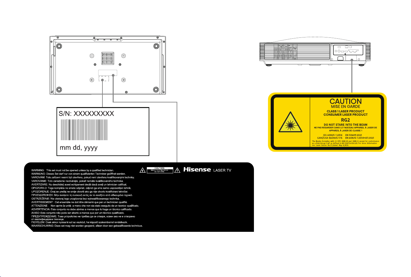
This page is used to show the position of the nameplate, and the content is for reference only.
Bottom View
Back View
17
1426289 ES-A2527Z0-1