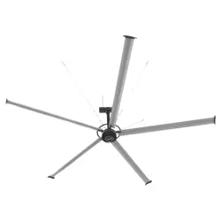
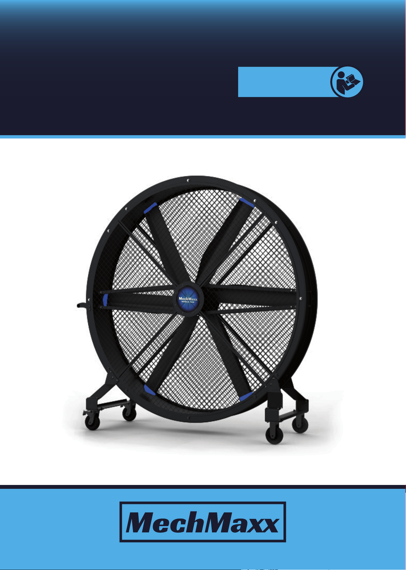
PM MOTOR MOBILE
INDUSTRIAL FAN
Save This Manual for Future Reference
www.mechmaxx.com
CONTROLLER
INSTRUCTIONS
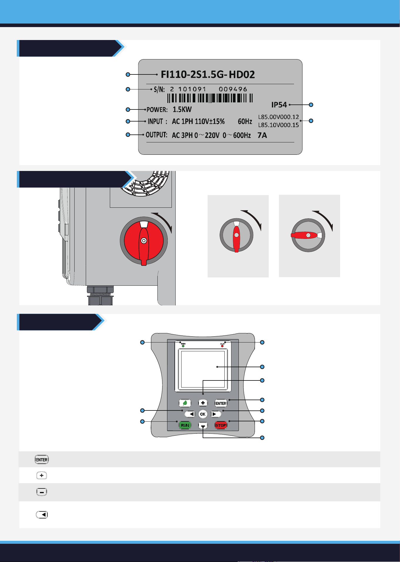
ControllerModel
ControllerSerialNumber
PowerRating
InputElectricalSpecifications
OutputElectricalSpecifications
ProtectionClass
SoftwareVersion
Run Indicator
Fault Indicator
Left Button
Run Button
Display Area
Increase Speed Button
Confirm Button
Right Button
Stop Button
Decrease Speed Button
www.mechmaxx.com
Pressandholdfor5secondsonthemaininterfacetoswitchtoTimerMode;onother
interfacesitmovesthecursortotheleft
LeftShiftButton
DecreaseSpeedButton Pressonceonthemaininterfacetodecreasethespeedby30RPM.
Usedtoconfirmselectionsorenterthemenu.
ConfirmButton
Pressonceonthemaininterfacetoincreasethespeedby30RPM.
IncreaseSpeedButton
OFF
OFF
ON
Power off
OFF
OFF
ON
Power on
ON
OFF
ON
ButtonFunctions
NameplateDescription
Power Switch Description
CONTROLLER INSTRUCTIONS
www.mechmaxx.com
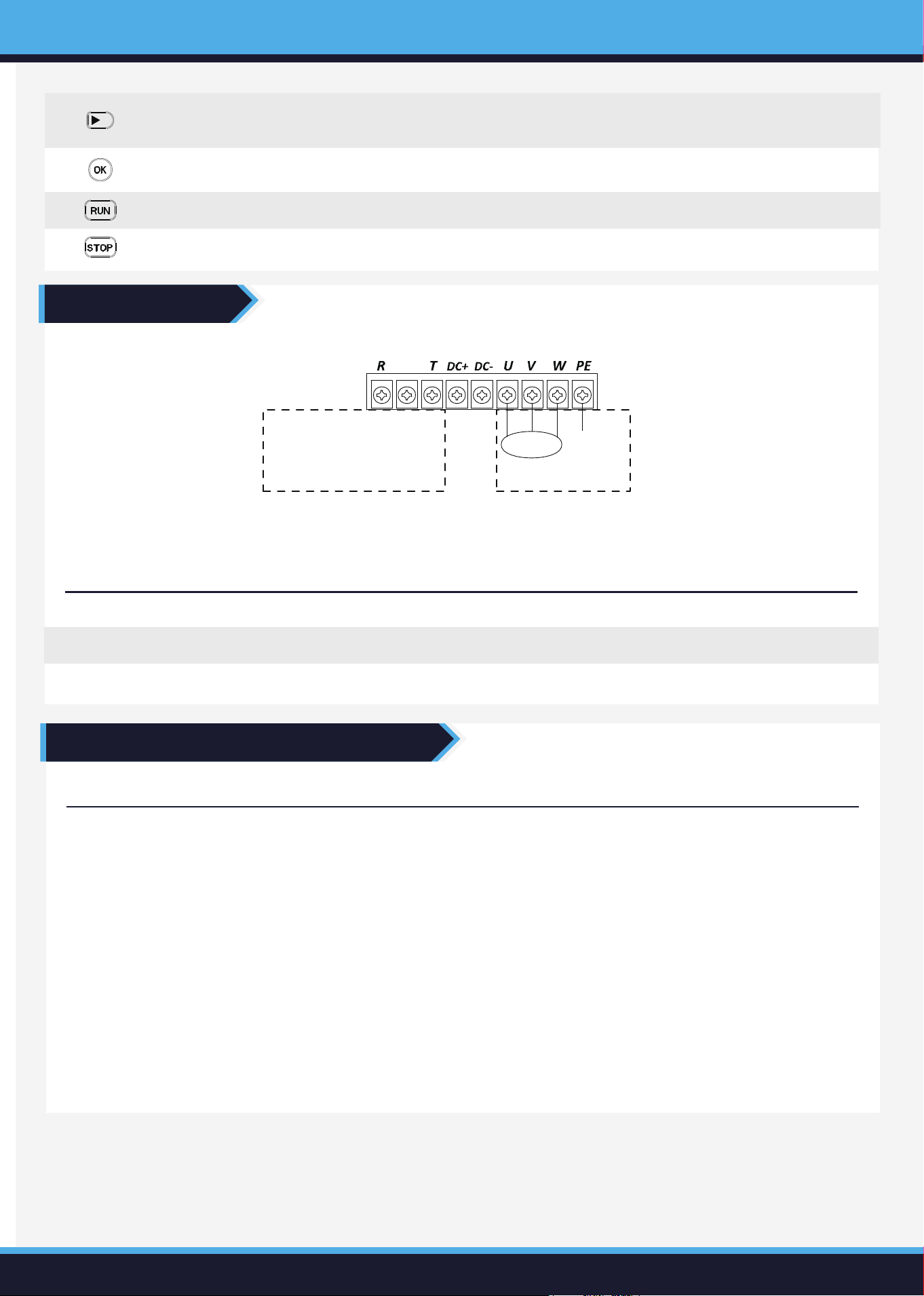
Single-Phase Power Supply Wiring (Power switch included as standard)
Single-Phase AC Power Wiring Diagram
R T
U V W
P E
Single-Phase AC Power Input Terminal Connect to the single-phase AC power supply
Inverter Output Terminals Connect to the three-phase motor
Ground Terminal Inverter Ground Terminal
Single-Phase Input Wiring
L N
Live
Neutral
Motor Ground
Output Wiring
Terminal Mark Function Description
Fault Code Fault Name Possible Cause Solution
E001
Excessive
Acceleration
Current
• Acceleration time is too short
• The inverter output is grounded or
short-circuited
• Motor parameter identification was not
performed in vector control mode
• Sudden load changes during acceleration
• Excessive manual torque boost or improp-
er V/F curve settings
• Low voltage
• Inverter size is too small for the applica-
tion
• Increase the time duration for accelera-
tion.
• Inspect the insulation of the motor and
cables.
• Perform parameter identification on the
motor.
• Check the load conditions.
• Reduce the torque boost value or adjust
the V/F curve settings.
• Verify the supply voltage or check the
bus voltage levels.
• Choose a frequency inverter with a
higher power rating.
Fault Code Diagnosis and Troubleshooting
Main Circuit Wiring
CONTROLLER INSTRUCTIONS
Run
Startthemachineoperation.esitmovesthecursortotheright.
Stop Stopthemachineoperation.
OKButton PressandholdtoenterSelf-LearningMode.
RightShiftButton
Pressandholdfor15secondsonthemaininterfacetochangetherotationdirection;
onotherinterfacesitmovesthecursortotheright.

www.mechmaxx.com
E002
Excessive
Deceleration
Current
Excessive
Constant
Speed
Current
Excessive
Acceleration
Voltage
Excessive
Deceleration
Voltage
Excessive
Constant
Speed Voltage
E003
• The output of the frequency inverter is
grounded or short-circuited.
• Motor parameter identification has not been
performed in vector control mode.
• Sudden load changes during operation.
• Low voltage.
• The selected frequency inverter is under-
sized.
• Inspect the insulation of the motor and
cables.
• Perform motor parameter identification.
• Check the load conditions.
• Check the supply voltage or inspect the
bus voltage.
• Choose a frequency inverter with a
higher power rating.
E004
• Input voltage is too high.
• The acceleration time is too short.
• External forces are dragging the motor
during acceleration.
• No braking unit or braking resistor is
installed.
• Adjust the voltage to the normal range.
• Increase the acceleration time.
• Check the load conditions.
• Install a braking unit and braking
resistor.
E005
• Input voltage is too high.
• The acceleration time is too short.
• External forces are dragging the motor
during acceleration.
• No braking unit or braking resistor is
installed.
• Adjust the voltage to the normal range.
• Increase the acceleration time.
• Check the load conditions.
• Install a braking unit and braking
resistor.
E006
• Input voltage is too high.
• External forces are dragging the motor
during operation.
• Adjust the input voltage to the normal
range.
• Adjust the load or install a braking unit
and braking resistor.
• The deceleration time is too short.
• The output of the frequency inverter is
grounded or short-circuited.
• Motor parameter identification has not been
performed in vector control mode.
• Sudden load changes during deceleration.
• Manual torque boost is too high or the V/F
curve is incorrectly set.
• Low voltage.
• Increase the deceleration time.
• Inspect the insulation of the motor and
cables.
• Perform motor parameter identification.
• Check the load conditions.
• Reduce the torque boost value or adjust
the V/F curve settings.
• Check the supply voltage or inspect the
bus voltage levels.
E011
• The wiring from the inverter to the motor
is abnormal.
• The inverter output has an imbalance in
the three-phase system or is missing a
phase.
• Drive board malfunction.
• Module malfunction.
• Inspect the motor and cables.
• Contact technical support.
Output Phase
Loss
Control Power
Failure
E007
• The input voltage is outside the specified
range.
• The relay does not activate.
• Adjust the input voltage to the normal
range.
E008
• Input voltage is too low or there is poor
contact at the contacts.
• Bus voltage is abnormal.
• Relay or contactor does not activate.
• Control board malfunction.
• Check the input power supply voltage.
• Check the bus voltage values.
• Seek technical support or replace the
contactor.
• Seek technical support.
Under Voltage
Fault
CONTROLLER INSTRUCTIONS
www.mechmaxx.com
Fault Code Fault Name Possible Cause Solution
• Never rely solely on the switch as the only means of disconnecting power when installing or servicing the fan. Failure to
follow this precaution can lead to serious electrical shock or even fatal injury.
• Always unplug the fan from the power outlet before servicing or cleaning it.
• Routine cleaning is the only maintenance required by the user. Any other repairs or servicing should be handled by qualified
professionals.
• Use a soft, damp cloth to wipe down the fan. Finish by wiping it with a dry cloth.
• Avoid using harsh cleaners that could damage the paint or plastic parts of the fan.
• Do not use gasoline, benzene, thinner, or other aggressive cleaners, as these may harm the fan and pose safety risks.
• If cleaning requires removing any guards, only remove the front guard and reinstall it in its original position after cleaning.
Do not attempt to repair the propeller if it is damaged. The propeller is factory-balanced and should be replaced if it
becomes damaged.
• To prevent overheating and ensure the fan operates efficiently, regularly clean the propeller, guard, and motor, as imbal-
anced or dirty components can lead to operational issues.
E012
• Motor ground short circuit.
• Misoperation.
• Inspect the motor and cables.
• Set PC.07 to 0 to disable the function.
E014
• Overloaded or motor is locked.
• Undersized inverter selection.
• Motor has not undergone self-learning.
• Check the load and mechanical condi-
tions.
• Replace with a frequency inverter of
higher power rating.
• Change the control mode to V/F
(PO.00=1) and restart, or perform
motor rotation self-learning.
E015
• Incorrect protection parameter setting
(PC.01).
• Overloaded or motor is locked.
• Undersized inverter selection.
• Correctly set the parameters.
• Check the load and mechanical
conditions.
• Replace with a higher power-rated
frequency inverter.
E016
E021
• Excessive ambient temperature.
• Blocked airflow ducts.
• Damaged fan.
• Overheated module components.
• Improve the ambient temperature.
• Clear the airflow ducts.
• Replace the fan.
• Contact technical support.
• Current Hall sensor damage.
• Drive board failure.
• Check if the Hall sensor and connec-
tor wires are loose.
• Contact technical support.
Ground Short
Circuit
Inverter
Overload
Motor
Overload
Module
Overheating
E026
• Incorrect motor parameter settings.
• Parameter identification time is too long.
• Reset the motor parameters.
• Check the connection between the
inverter and the motor.
Current
Detection Fault
Motor
Identification
Fault
E028
• Overloaded or motor is locked.
• Undersized inverter selection.
• Motor has not undergone self-learning.
• Check the motor and load.
• Perform motor parameter self-identifi-
cation.
• Change the control mode to V/F
(PO.00=1) and restart, or perform
motor rotation self-learning.
Quick Current
Limiting Fault
Maintenance and Cleaning Instructions
CONTROLLER INSTRUCTIONS