Installation Guide
© 2026 TP-Link 7100002687 REV2.0.0
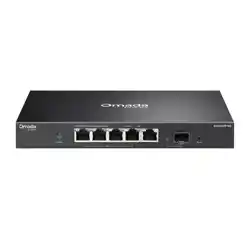
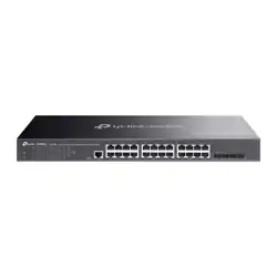
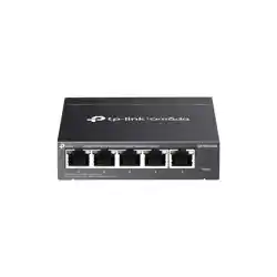
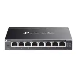
Omada 2.5G PoE++ Easy Managed Switch
LED Explanation
LED Explanation
Power
On/O: Power on/o
Link/Act
Desktop:
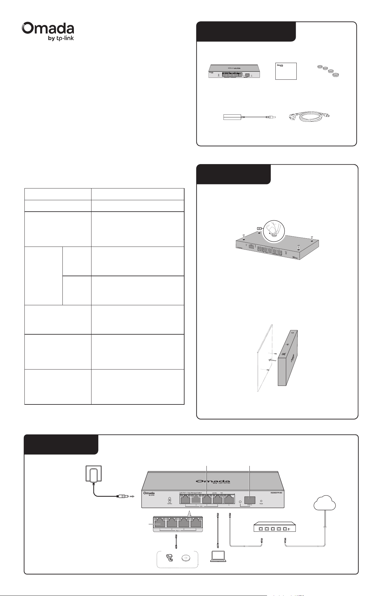
Attach the supplied rubber feet to the bottom of the switch to
prevent it from slipping when placed on a desktop.
Wall-mounting:
Drill two holes on the wall according to the mounting holes
on the bottom of the switch, then secure the switch to the
wall with two suitable screws (not provided).
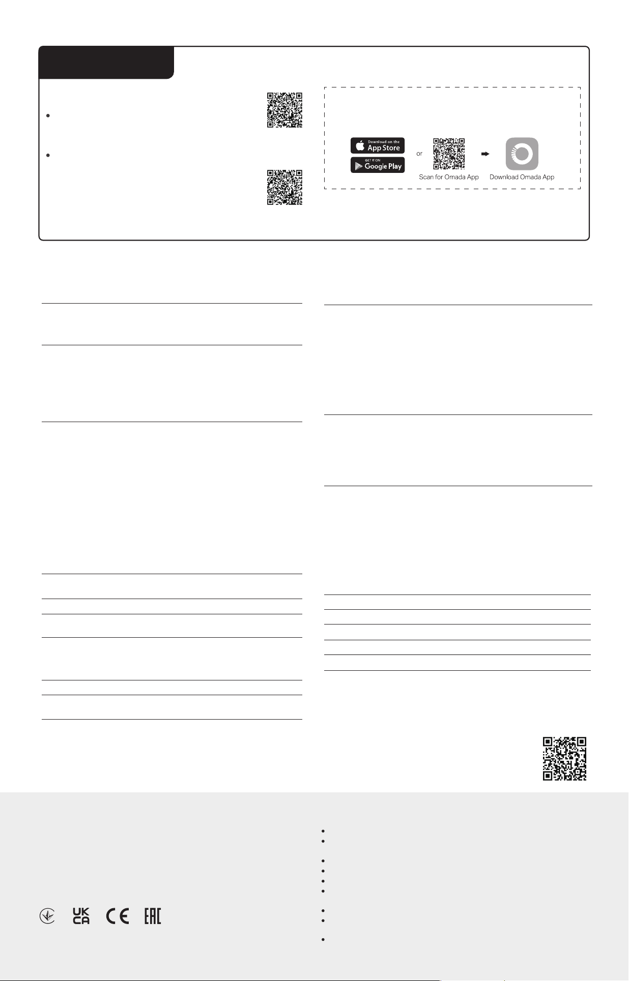
Connection
(For ports 1-5 of ES206XPP-M2/
ports 1-8 of ES210XPP-M2)
On (Green): Running at 2.5 Gbps
On (Yellow): Running at 100/1000 Mbps
Blinking: Transmitting/receiving data
O: No connected device
Power Adapter
Ethernet Ports (1–5) SFP+ Port (6)
Installation
PoE
PoE Max
Right LED
Left LED
Link/Act
(For port 9 of
ES210XPP-M2)
On (Green): Running at 10 Gbps
On (Yellow): Running at 5 Gbps
Blinking: Transmitting/receiving data
O: No connected device
On (Green): Running at 2.5 Gbps
On (Yellow): Running at 100/1000 Mbps
Blinking: Transmitting/receiving data
O: No connected device
On (Green): Running at 10 Gbps
On (Yellow): Running at 1000 Mbps
Blinking: Transmitting/receiving data
O: No connected device
SFP+
(For ports 1-4 of ES206XPP-M2/
ports 1-8 of ES210XPP-M2)
(For port 6 of ES206XPP-M2/
port 10 of ES210XPP-M2)
On: Providing PoE power
Blinking: Current-overload/Short-circuit
O: Not providing PoE Power
On: The remaining PoE power is ≤ 7 W
Blinking: The remaining PoE power
keeps ≤ 7 W for more than 2 minuites
O: The remaining PoE power is > 7 W
IP Camera AP
Powered Device (PD)
Gateway
LAN Port
WAN Port
PC
PoE++ Ports
(1-4)
Internet
Note:
1. The PoE ports can also connect to non-PoE
devices, but only transmit data.
2. The PoE ports shall not be used to charge lithium
batteries or devices supplied by lithium batteries.
3. Maximum PoE power is 90 W for each PoE port,
and total PoE budget is 120 W (for ES206XPP-M2)/
200 W (for ES210XPP-M2).
4. PoE budget calculations are based on laboratory
testing. Actual PoE power budget is not
guaranteed and will vary as a result of client
limitations and environmental factors.
Package Contents
DC Power Adapter AC Power Cord
Note: For simplicity, we will take ES206XPP-M2 for example throughout the Guide. The images in this
guide are for demonstration only and may dier from your actual product.
Switch Rubber FeetInstallation Guide
Installation Guide
Note:
Ensure enough clearance between the switch and the wall for air circulation.
For detailed information, refer to the Wall Mounting Guide at
https://support.omadanetworks.com/document/901/.
Note:
Avoid placing the switch on top of another and use the rubber feet to ensure
enough clearance for air circulation.
EU declaration of conformity
TP-Link hereby declares that the switch is in compliance with the essential requirements and other
relevant provisions of directives 2014/30/EU, 2014/35/EU, 2011/65/EU and (EU)2015/863.
The original EU declaration of conformity may be found at https://www.tp-link.com/en/support/ce/
UK declaration of conformity
TP-Link hereby declares that the switch is in compliance with the essential requirements and other
relevant provisions of the Electromagnetic Compatibility Regulations 2016 and Electrical
Equipment (Safety) Regulations 2016.
The original UK declaration of conformity may be found at https://www.tp-link.com/support/ukca/
Safety Information
packing of this product. If you have any questions, please don’t hesitate to contact us.
Use only power supplies which are provided by manufacturer and in the origin
Do not use any other chargers than those recommended.
Keep the device away from water, re, humidity or hot environments.
Do not use damaged charger or USB cable to charge the device.
Adapter shall be installed near the equipment and shall be easily accessible.
Do not attempt to disassemble, repair, or modify the device. If you need service,
please contact us.
The socket-outlet shall be installed near the equipment and shall be easily accessible.
Plug the product into the wall outlets with earthing connection through the power
supply cord.
Place the device with its bottom surface downward.
Conguration
Omada App
With the TP-Link Omada app, you can access and manage your Omada
devices at a local site or remotely with a tap of your phone. You can download
and install the TP-Link Omada app from the App Store or Google Play.
For detailed instructions on device conguration, refer to the user guides of the
Controller and switches. The guides can be found in the support center of our
ocial website: https://support.omadanetworks.com/document/.
The switch supports two conguration methods:
Scan for Standalone
Conguration Guide
Scan for Controller
Conguration Guide
Standalone Mode: Congure and manage the switch individually.
To set up a standalone Omada switch, scan the QR code or refer to
https://www.omadanetworks.com/support/faq/4097/.
Controller Mode: Congure and manage the network devices
centrally. This mode is recommended for large-scale networks
with numerous devices, including access points, switches, and
gateways.
To set up an Omada switch with an Omada Controller, scan the
QR code or refer to the Omada Controller conguration guide
at https://www.omadanetworks.com/support/faq/4096/.
Specications
General Specications
Standard
IEEE 802.3, IEEE 802.3u, IEEE 802.3ab, IEEE 802.3bz,
IEEE 802.3an (for ES210XPP-M2), IEEE 802.3z, IEEE 802.3ae
IEEE 802.3az, IEEE 802.3x, IEEE 802.1p, IEEE 802.1q
IEEE 802.3af, IEEE 802.3at, IEEE 802.3bt
Interface
ES206XPP-M2:
4 × 100M/1G/2.5G RJ45 PoE++ Ports
1 × 100M/1G/2.5G RJ45 Port
1 × 10G SFP+ Port
ES210XPP-M2:
8 × 100M/1G/2.5G RJ45 PoE++ Ports
1 × 100M/1G/2.5G/5G/10G RJ45 Port
1 × 10G SFP+ Port
Transmission
Media
100BASE-TX: UTP category 5, 5e cable (maximum 100 m)
1000BASE-T: UTP category 5e cable or above (maximum 100 m)
1000BASE-SX: 62.5 μm MMF (2 m ~ 275 m) or 50 μm MMF (2 m ~
550 m)
1000BASE-LX: 62.5/50 μm MMF (2 m ~ 550 m) or 9 μm SMF (2 m ~
5000 m)
1000BASE-LX10: B1.1, B1.3 SMF (2 ber) (0.5 m ~ 10 km)
1000BASE-BX10: B1.1, B1.3 SMF (1 ber) (0.5 m ~ 10 km)
2.5GBASE-T: UTP category 5e cable or above (maximum 100 m)
5GBASE-T: UTP/STP category 5e cable or above (maximum 100 m)
(for ES210XPP-M2)
10GBASE-T: UTP category 6 cable (maximum 55m), STP category
6/6a/7 cable, or UTP category 6a cable (maximum 100m) (for
ES210XPP-M2)
10GBASE-SR: OM1/OM2/OM3 or above MMF (2 m ~ 300 m)
10GBASE-LR: IEC B1.1 and B1.3 SMF (2 m ~ 10 km)
Switching
Capacity
ES206XPP-M2: 45 Gbps
ES210XPP-M2: 80 Gbps
Transfer Method Store-and-Forward
MAC Address
Learning
Automatically learning, automatically aging
Power Supply
Input: 100-240 VAC, 50/60 Hz
Output:
ES206XPP-M2: 53.5 V DC/2.43 A
ES210XPP-M2: 54 V DC/4.16 A
Wall Mountable Ye s
Distance Between
Mounting Holes
150 mm
Frequently Asked Questions (FAQ)
The Power LED should be lit when the power system is working normally. If the Power
LED is not lit, please check as follows:
A1:
Make sure the switch and power source are properly connected through the power
adapter.
A2:
Make sure the power source voltage meets the input voltage requirements of both
the power adapter and the switch.
A3:
Make sure the power source is on.
Q1. The Power LED is not lit.
It is recommended that you check the following items:
A1:
Make sure that the cable connectors are rmly plugged into the switch and the device.
A2:
Make sure the connected device is turned on and working well.
A3:
The cable must be less than 100 meters long (328 feet).
Q2. Why is the Link/Act LED not lit while a device is connected to
the corresponding port?
When the total power consumption of connected PoE devices exceeds the maximum,
the PoE port with a smaller port number has a higher priority. The system will cut o
power to the ports with larger port numbers to ensure supplying to other ports.
Take ES206XPP-M2 for example, if port 1, 2 and 4 are consuming 30 W respectively, and
an additional PoE device with 60 W is connected to port 3, the system will cut o the
power of port 4 to compensate for the overload.
Q3. Why is PoE Port not supplying power for PoE devices?
More Resources
Main Site
Video Center
Documents
Product Support
Technical Support
https://www.omadanetworks.com/
https://support.omadanetworks.com/video/
https://support.omadanetworks.com/document/
https://support.omadanetworks.com/product/
https://support.omadanetworks.com/contact-support/
Warranty
For details on the warranty period, policy, and procedures, visit
https://support.omadanetworks.com/warranty-services.
Support
For technical support, user guides and other information,
please visit https://support.omadanetworks.com/, or simply
scan the QR code.