
Installation Guide
Omada Access/Access Plus/Access Max/Aggregation/Campus
Managed Switch
Business Networking Solution

About this Installation Guide
This Installation Guide describes the hardware characteristics, installation methods and the
points that should be attended to during the installation. This Installation Guide is structured as
follows:
Chapter 1 Introduction
This chapter describes the external components of the switch.
Chapter 2 Installation
This chapter illustrates how to install the switch.
Chapter 3 Connection
This chapter illustrates how to do the physical connection of the switch.
Chapter 4 Configuration
This chapter illustrates how to configure the switch.
Appendix A Troubleshooting
Appendix B Specifications
Conventions
• Some models featured in this guide may be unavailable in your country or region. For local sales
information, visit https://www.omadanetworks.com/.
• The figures in Chapter 2, Chapter 3, and Chapter 4 are for demonstration purposes only. Your
switch may differ in appearance from that depicted.
• PoE budget calculations are based on laboratory testing. Actual PoE power budget is not
guaranteed and will vary as a result of client limitations and environmental factors.
• This guide uses the specific formats to highlight special messages. The following table lists the
notice icons that are used throughout this guide.
Remind to be careful. A caution indicates a potential which may result in device damage.
Remind to take notice. The note contains the helpful information for a better use of the
product.
Related Document
The User Guide and CLI Reference Guide of the product are provided on Download Center. To
obtain the latest product information, visit the official website:
https://support.omadanetworks.com/document/
.

Contents
Chapter 1 Introduction ——————————— 01
1.1 Product Overview ...........................................................01
1.2 Appearance .......................................................................01
Chapter 2 Installation ——————————— 11
2.1 Package Contents ..........................................................11
2.2 Safety Precautions .........................................................11
2.3 Installation Tools ..............................................................13
2.4 Product Installation ........................................................13
Chapter 3 Connection ——————————— 15
3.1 Ethernet Port ....................................................................15
3.2 SFP/SFP+ Slot ..................................................................15
3.3 Console Port .....................................................................15
3.4 Verify Installation .............................................................16
3.5 Power On ............................................................................16
3.6 Initialization ........................................................................17
3.7 Stack Topology ................................................................17
Chapter 4 Conguration —————————— 20
4.1 Conguration Overview ................................................20
4.2 Standalone Mode ............................................................20
4.3 Controller Mode ...............................................................21
Appendix A Troubleshooting ———————— 24
Appendix B Specications ————————— 25
Omada Access/Access Plus/Access Max/Aggregation/Campus Managed Switch
01Introduction
Chapter 1 Introduction
1.1 Product Overview
The Omada Access/Access Plus/Access Max/Aggregation/Campus Managed Switch is designed for
medium businesses. In addition to wire-speed performance, they can provide abundant L2 and L2/L3
management features respectively. A variety of service features and multiple powerful functions with high
security are also available.
The EIA-standardized framework and smart configuration capacity can provide flexible solutions for a
variable scale of networks. For Campus switches, RIP, and OSPF come with abundant Layer 3 routing
protocols that support a scalable network. Physical stacking for built-in redundancy and performance.
ERPS supports rapid protection and recovery in a ring topology.
All types of switches are embedded with powerful software features: ACL, 802.1x and Dynamic ARP
Inspection provide robust security strategies. QoS and IGMP snooping/filtering optimize voice and
video application. Link aggregation (LACP) increases aggregated bandwidth, optimizing the transport of
business critical data. SNMP, RMON, WEB and CLI Log-in bring abundant management policies.
The switches integrate multiple functions with excellent performance, and are friendly to manage, which
can fully meet the need of the users demanding higher networking performance.
SG3428MP/SG3428XMP/SG3428XMPP/SG5428XMPP/SG5452XMPP is also a Power Sourcing Equipment
(PSE*). All the RJ45 ports on the switch support Power over Ethernet (PoE*) function, which can
automatically detect and supply power to those powered devices (PDs*) compliant with IEEE 802.3af and
IEEE 802.3at. Additionally, SG3428XMPP/SG5428XMPP/SG5452XMPP can also power PDs compliant with
IEEE 802.3bt.
Note:
■
PSE: a device (switch or hub for instance) that provides power through an Ethernet cable.
■
PoE: This technology describes a system to transmit electrical power, along with data, to remote
devices over standard twisted-pair cable in an Ethernet.
■
PD: a device powered by a PSE and thus consumes energy. Examples include powering network
cameras, wireless LAN access points, IP telephones, network hubs, embedded computers etc.
1.2 Appearance
■
Front Panel
(The gures are for demonstration only. They may dier from your actual products.)
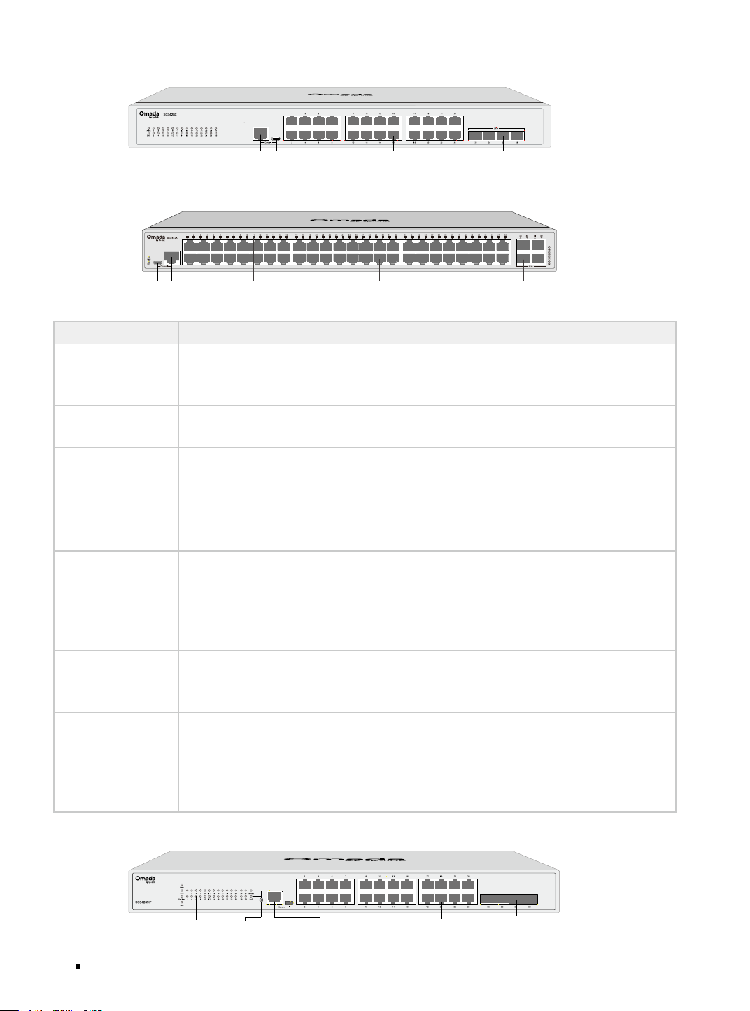
The front panel of SG3210 is shown as the following figure.
LED Console Port
(RJ45/USB)
1G RJ45 Port SFP Slot
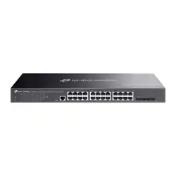
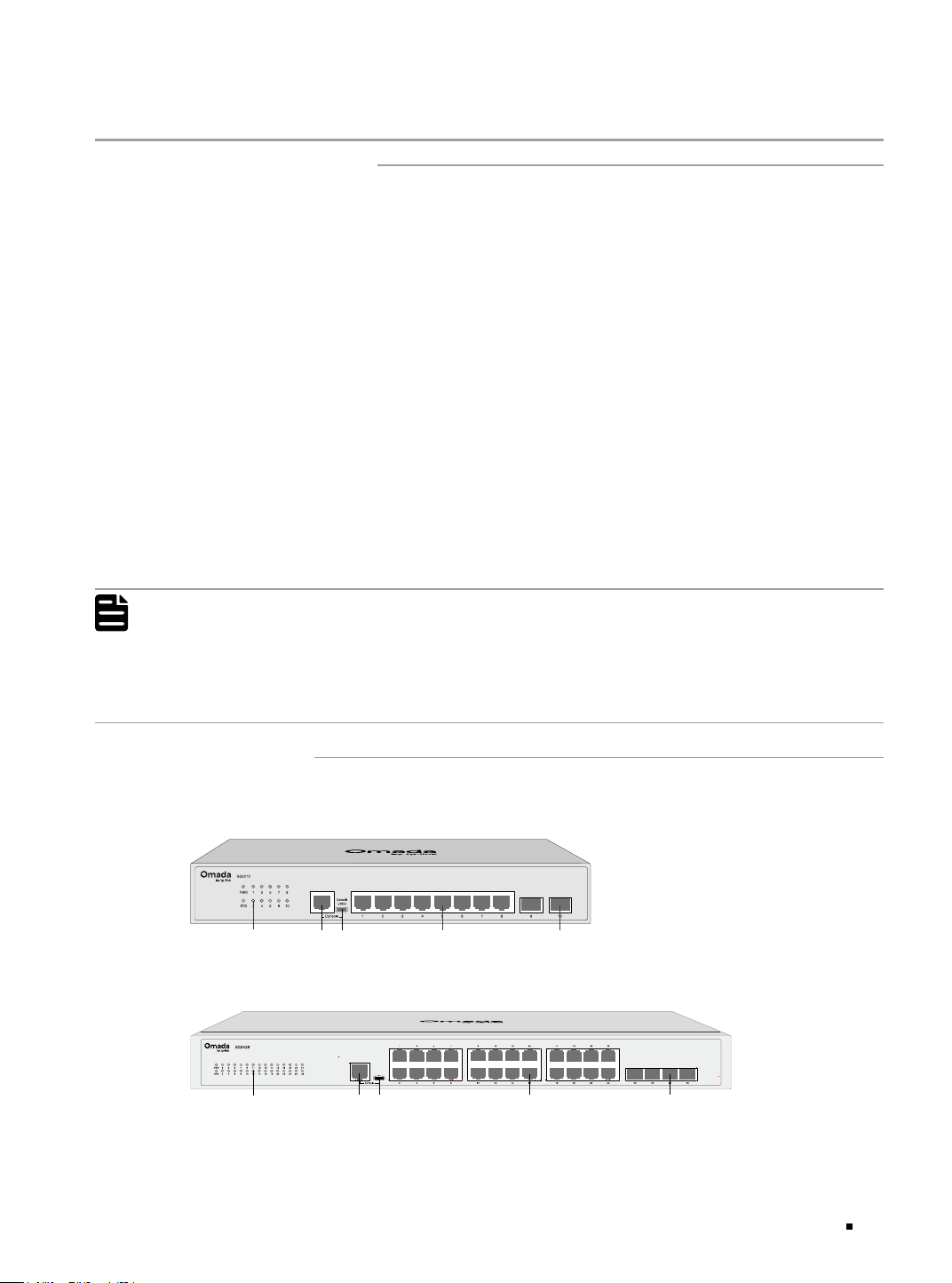
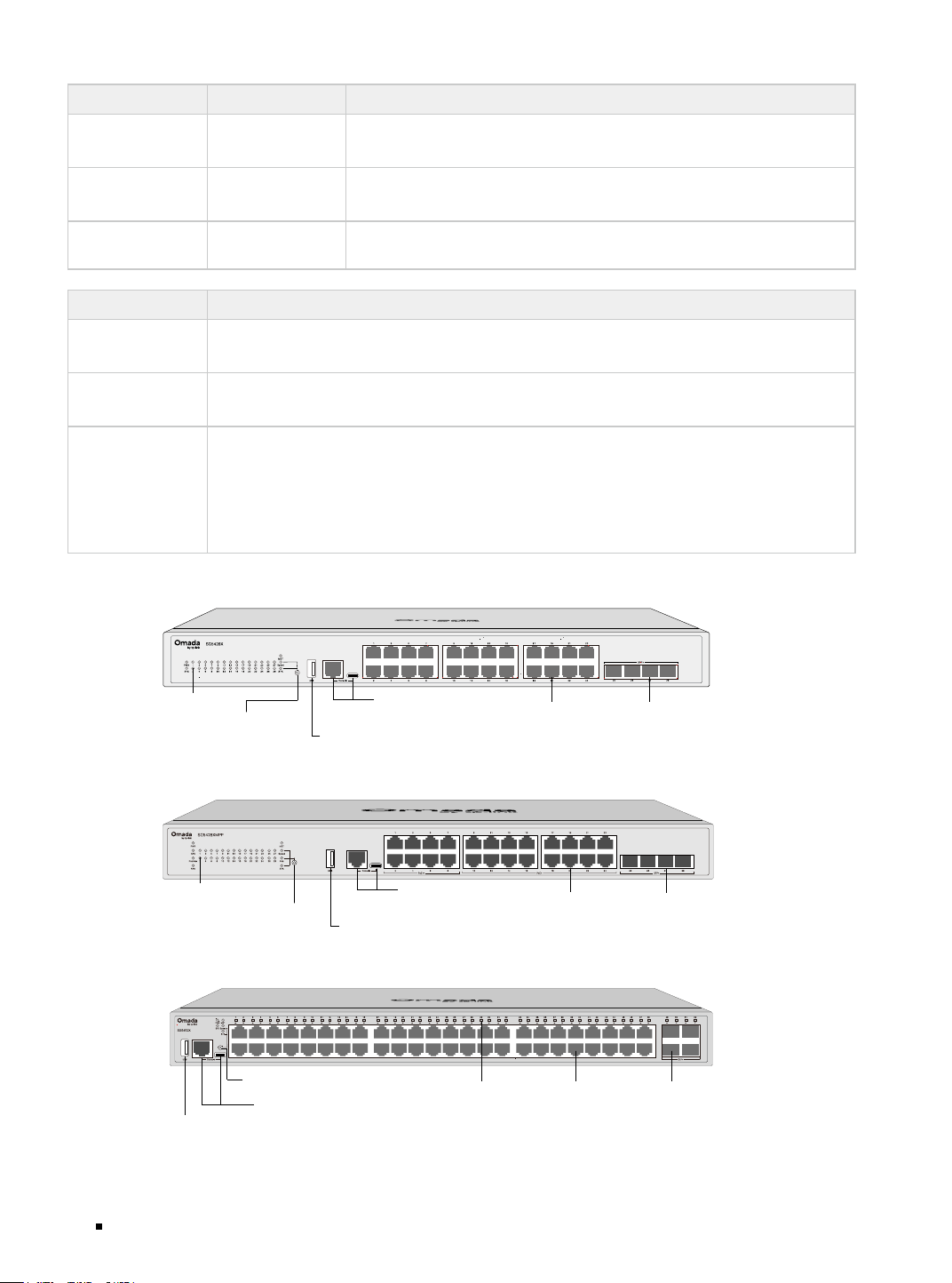
The front panel of SG3428 is shown as the following figure.
LED Console Port
(RJ45/Type-C)
1G
RJ45 Port
SFP Slot
Omada Access/Access Plus/Access Max/Aggregation/Campus Managed Switch
02 Introduction
The front panel of SG3428X is shown as the following figure.
LED Console Port
(RJ45/Type-C)
1G
RJ45 Port
SFP+ Slot
The front panel of SG3452X is shown as the following figure.
LED
1G RJ45 Port
SFP+ Slot
Console Port
(USB/RJ45)
LED Indication
PWR
On: The switch is powered on.
Off: The switch is powered off or power supply is abnormal.
Flashing: Power supply is abnormal.
SYS
Flashing: The switch works properly.
On or Off: The switch works improperly.
Speed
Green On: Running at 1000 Mbps, but no activity.
Green Flashing: Running at 1000 Mbps and transmitting or receiving data.
Yellow On: Running at 10/100 Mbps, but no activity.
Yellow Flashing: Running at 10/100 Mbps and transmitting or receiving data.
Off: No device is linked to the corresponding port.
SFP
(Only For SG3210)
Green On: Running at 1000 Mbps, but no activity.
Green Flashing: Running at 1000 Mbps and transmitting or receiving data.
Yellow On: Running at 100 Mbps, but no activity.
Yellow Flashing: Running at 100 Mbps and transmitting or receiving data.
Off: No device is linked to the corresponding port.
SFP
(Only For SG3428)
On: Running at 1 Gbps, but no activity.
Flashing: Running at 1 Gbps and transmitting or receiving data.
Off: No device is linked to the corresponding port.
SFP+
(For SG3428X &
SG3452X)
Green On: Running at 10 Gbps, but no activity.
Green Flashing: Running at 10 Gbps and transmitting or receiving data.
Yellow On: Running at 1 Gbps, but no activity.
Yellow Flashing: Running at 1 Gbps and transmitting or receiving data.
Off: No device is linked to the corresponding port.
The front panel of SG3428MP is shown as the following figure.
LED
Console Port
(RJ45/USB)
1G
RJ45 Port
SFP Slot
Mode Selection
Button
Omada Access/Access Plus/Access Max/Aggregation/Campus Managed Switch
03Introduction
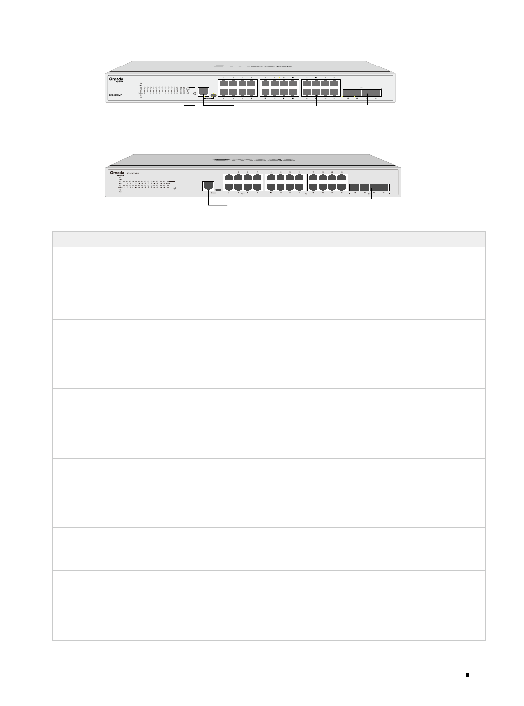
The front panel of SG3428XMP is shown as the following figure.
LED
Console Port
(RJ45/USB)
1G
RJ45 Port
SFP+ Slot
Mode Selection
Button
The front panel of SG3428XMPP is shown as the following figure.
Console Port
(RJ45/USB)
LED 1G
RJ45 Port
SFP+ Slot
Mode Selection
Button
LED Indication
PWR
On: The switch is powered on.
Off: The switch is powered off or power supply is abnormal.
Flashing: Power supply is abnormal.
SYS
Flashing: The switch works properly.
On or Off: The switch works improperly.
PoE Max
On: The remaining PoE power is ≤ 7 W.
Flashing: The remaining PoE power keeps ≤ 7 W after this LED is on for 2 minutes.
Off: The remaining PoE power is > 7 W.
FAN
Green: All the fans work properly.
Yellow: Not all the fans work properly.
Port 1–24
(When the Speed LED is on)
Green On: Running at 1000 Mbps, but no activity.
Green Flashing: Running at 1000 Mbps and transmitting or receiving data.
Yellow On: Running at 10/100 Mbps, but no activity.
Yellow Flashing: Running at 10/100 Mbps and transmitting or receiving data.
Off: No device is linked to the corresponding port.
Port 1–24
(When the PoE LED is on)
Green On: The port is supplying power normally.
Green Flashing: The supply power exceeds the correponding port's maximum
power.
Yellow On: Overload or short circuit is detected.
Yellow Flashing: Power-on self-test failed.
Off: Not providing PoE power on the port.
SFP
(For SG3428MP)
On: Running at 1 Gbps, but no activity.
Flashing: Running at 1 Gbps and transmitting or receiving data.
Off: No device is linked to the corresponding port.
SFP+
(For SG3428XMP &
SG3428XMPP)
Green On: Running at 10 Gbps, but no activity.
Green Flashing: Running at 10 Gbps and transmitting or receiving data.
Yellow On: Running at 1 Gbps, but no activity.
Yellow Flashing: Running at 1 Gbps and transmitting or receiving data.
Off: No device is linked to the corresponding port.
Omada Access/Access Plus/Access Max/Aggregation/Campus Managed Switch
04 Introduction
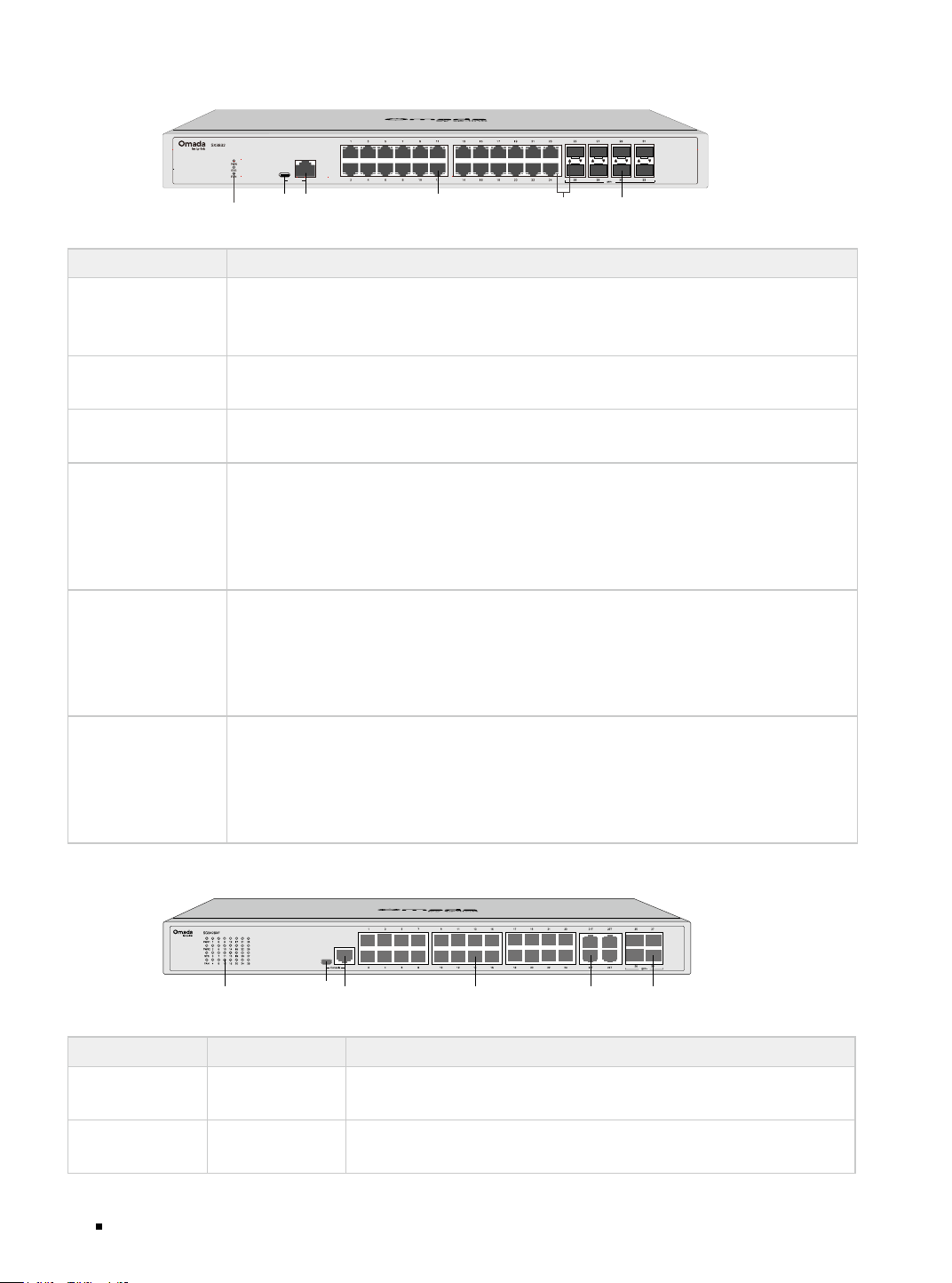
The front panel of SX3832 is shown as the following figure.
Console
SFP+ Slot
LED
Console Port
(Type-C/RJ45)
LED
10G RJ45 Port
LED Indication
PWR
On: The switch is powered on.
Off: The switch is powered off or power supply is abnormal.
Flashing: Power supply is abnormal.
SYS
Flashing: The switch works properly.
On or Off: The switch works improperly.
FAN
Green: All the fans work properly.
Yellow: Not all the fans work properly.
Port 1–24
(Left LED)
Green On: Running at 10 Gbps, but no activity.
Green Flashing: Running at 10 Gbps and transmitting or receiving data.
Yellow On: Running at 5 Gbps, but no activity.
Yellow Flashing: Running at 5 Gbps and transmitting or receiving data.
Off (Both Left and Right): No device is linked to the corresponding port.
Port 1–24
(Right LED)
Green On: Running at 2.5 Gbps, but no activity.
Green Flashing: Running at 2.5 Gbps and transmitting or receiving data.
Yellow On: Running at 10/100/1000 Mbps, but no activity.
Yellow Flashing: Running at 10/100/1000 Mbps and transmitting or receiving data.
Off (Both Left and Right): No device is linked to the corresponding port.
SFP+
Green On: Running at 10 Gbps, but no activity.
Green Flashing: Running at 10 Gbps and transmitting or receiving data.
Yellow On: Running at 1 Gbps, but no activity.
Yellow Flashing: Running at 1 Gbps and transmitting or receiving data.
Off: No device is linked to the corresponding port.
The front panel of SG3428XF is shown as the following figure.
LED Console Port
(USB/RJ45)
1G
RJ45 Port
SFP+ SlotSFP Slot
PWR1* PWR2 Indication
Green On Off
The switch is powered by PWR1.
PWR2 is disconnected or it works improperly.
Green On Yellow On**
The switch is powered by PWR1.
PWR1 and PWR2 are connected.*
Omada Access/Access Plus/Access Max/Aggregation/Campus Managed Switch
05Introduction
PWR1* PWR2 Indication
Off Green On
The switch is powered by PWR2.
PWR1 is disconnected or it works improperly.
Off Off
The switch is powered off or both PWR1 and PWR2 work
improperly.
*PWR1 is the primary power supply and it takes priority over PWR2.
**When both PWR1 and PWR2 work properly and the switch is powerd by PWR1, it takes 10-20 seconds for
the LED PWR2 (yellow) to go out after PWR2 is unplugged.
LED Indication
SYS
Flashing: The switch works properly.
On or Off: The switch works improperly.
FAN
Green: All the fans work properly.
Yellow: Not all the fans work properly.
Port 1-24
Green On: Running at 1000 Mbps, but no activity.
Green Flashing: Running at 1000 Mbps and transmitting or receiving data.
Yellow On: Running at 100 Mbps, but no activity.
Yellow Flashing: Running at 100 Mbps and transmitting or receiving data.
Off: No device is linked to the corresponding port.
Port 25–28
Green On: Running at 10 Gbps, but no activity.
Green Flashing: Running at 10 Gbps and transmitting or receiving data.
Yellow On: Running at 1 Gbps, but no activity.
Yellow Flashing: Running at 1 Gbps and transmitting or receiving data.
Off: No device is linked to the corresponding port.
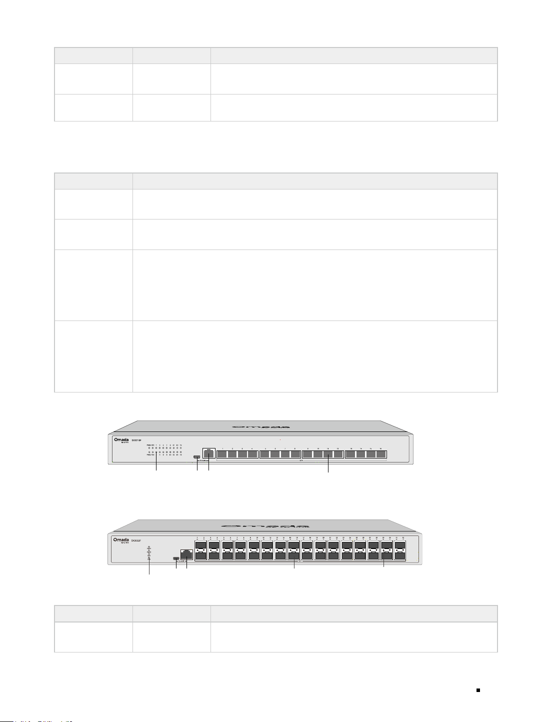
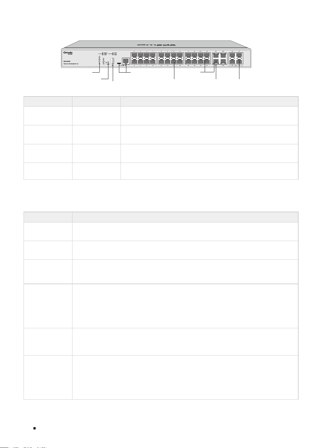
The front panel of SX3016F is shown as the following figure.
1G
RJ45 Port
LED
Console Port
(USB/RJ45)
SFP+ Slot
The front panel of SX3032F is shown as the following figure.
SFP+ Slot
LED
Console Port
(USB/RJ45)
LED
PWR1* PWR2 Indication
Green On Off
The switch is powered by PWR1.
PWR2 is disconnected or it works improperly.
Omada Access/Access Plus/Access Max/Aggregation/Campus Managed Switch
06 Introduction
PWR1* PWR2 Indication
Green On Yellow On**
The switch is powered by PWR1.
PWR1 and PWR2 are connected.*
Off Green On
The switch is powered by PWR2.
PWR1 is disconnected or it works improperly.
Off Off
The switch is powered off or both PWR1 and PWR2 work
improperly.
LED Indication
SYS
Flashing: The switch works properly.
On or Off: The switch works improperly.
FAN
Green: All the fans work properly.
Yellow: Not all the fans work properly.
Port 1
–
16 of
SX3016F/
Port 1-32 of
SX3032F
Green On: Running at 10 Gbps, but no activity.
Green Flashing: Running at 10 Gbps and transmitting or receiving data.
Yellow On: Running at 1 Gbps, but no activity.
Yellow Flashing: Running at 1 Gbps and transmitting or receiving data.
Off: No device is linked to the corresponding port.
The front panel of SG5428X is shown as the following figure.
LED
Console Port
(RJ45/Type-C)
1G RJ45 Port SFP+ Slot
USB2.0 Port
Mode Selection
Button
The front panel of SG5428XMPP is shown as the following figure.
LED
Console Port
(RJ45/Type-C)
1G RJ45 Port SFP+ Slot
USB2.0 Port
Mode Selection
Button
The front panel of SG5452X is shown as the following figure.
LED
Console Port (RJ45/Type-C)
1G RJ45 Port SFP+ Slot
Mode Selection Button
USB2.0 Port
Omada Access/Access Plus/Access Max/Aggregation/Campus Managed Switch
07Introduction
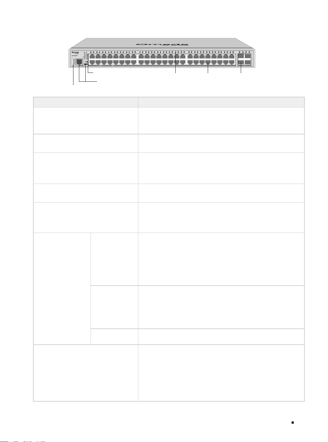
The front panel of SG5452XMPP is shown as the following figure.
LED
Console Port (RJ45/Typc-C)
1G RJ45 Port SFP+ Slot
Mode Selection Button
USB2.0 Port
LED Indication
PWR
On: The switch is powered on.
Off: The switch is powered off or power supply is abnormal.
Flashing: Power supply is abnormal.
SYS
Flashing: The switch works properly.
On or Off: The switch works improperly.
PoE MAX
(For SG5428XMPP & SG5452XMPP)
On: The remaining PoE power is ≤ 7 W.
Flashing: The remaining PoE power keeps ≤ 7 W after this LED is
on for 2 minutes.
Off: The remaining PoE power is > 7 W.
FAN
(For SG5428XMPP & SG5452XMPP)
Green On: All the fans work properly.
Yellow On: Not all the fans work properly.
MST
On: The device functions as the master switch in the stack
topology or it works individually.
Off: The device functions as the member switch in the stack
topology.
Port 1-24 of SG5428
& SG5428XMPP/
Port1-48 of SG5452
& SG5452XMPP
When the Speed
LED is on
Green On: Running at 1000 Mbps, but no activity.
Green Flashing: Running at 1000 Mbps and transmitting or
receiving data.
Yellow On: Running at 10Mbps/100 Mbps, but no activity.
Yellow Flashing: Running at 10Mbps/100 Mbps and transmitting
or receiving data.
Off: No device is linked to the corresponding port.
When the PoE LED
is on
(Only for SG5428XMPP
& SG5452XMPP)
Green On: The port is supplying power normally.
Green Flashing: The supply power exceeds the correponding
port's maximum power.
Yellow On: Overload or short circuit is detected.
Yellow Flashing: Power-on self-test failed.
Off: Not providing PoE power on the port.
When the STK LED
is on
On: The port number indicates the unit ID in the stack topology.
SFP+
Green On: Running at 10 Gbps, but no activity.
Green Flashing: Running at 10 Gbps and transmitting or
receiving data.
Yellow On: Running at 1 Gbps, but no activity.
Yellow Flashing: Running at 1 Gbps and transmitting or
receiving data.
Off: No device is linked to the corresponding port.
Omada Access/Access Plus/Access Max/Aggregation/Campus Managed Switch
08 Introduction
The front panel of SG5428XF is shown as the following gure.
LED
Console Port
(Type-C/RJ45)
1G RJ45 Port SFP+ Slot
USB2.0 Port
Mode Selection
Button
SFP Slot
LED
PWR1* PWR2 Indication
Green On Off
The switch is powered by PWR1.
PWR2 is disconnected or it works improperly.
Green On Yellow On**
The switch is powered by PWR1.
PWR1 and PWR2 are connected.*
Off Green On
The switch is powered by PWR2.
PWR1 is disconnected or it works improperly.
Off Off
The switch is powered off or both PWR1 and PWR2 work
improperly.
*PWR1 is the primary power supply and it takes priority over PWR2.
**When both PWR1 and PWR2 work properly and the switch is powerd by PWR1, it takes 10-20 seconds for
the LED PWR2 (yellow) to go out after PWR2 is unplugged.
LED Indication
SYS
Flashing: The switch works properly.
On or Off: The switch works improperly.
FAN
Green: All the fans work properly.
Yellow: Not all the fans work properly.
MST
On: The device functions as the master switch in the stack topology or it works
individually.
Off: The device functions as the member switch in the stack topology.
Port 1-24
(When the Speed
LED is on)
Green On: Running at 1000 Mbps, but no activity.
Green Flashing: Running at 1000 Mbps and transmitting or receiving data.
Yellow On: Running at 100 Mbps, but no activity.
Yellow Flashing: Running at 100 Mbps and transmitting or receiving data.
Off: No device is linked to the corresponding port.
Port 1-24
(When the STK LED
is on)
On: The port number indicates the unit ID in the stack topology.
Port 25–28
(When the Speed
LED is on)
Green On: Running at 10 Gbps, but no activity.
Green Flashing: Running at 10 Gbps and transmitting or receiving data.
Yellow On: Running at 1 Gbps, but no activity.
Yellow Flashing: Running at 1 Gbps and transmitting or receiving data.
Off: No device is linked to the corresponding port.
Omada Access/Access Plus/Access Max/Aggregation/Campus Managed Switch
09Introduction
Port Feature
Model
10 M/100 M/1 G/2.5 G/
5 G/10 Gbps
RJ45 Port
10/100/1000 Mbps
RJ45 Port
SFP+ Slot SFP Slot Console Port USB Port
SG3210 / 8 / 2 2 /
SG3428 / 24 / 4 2* /
SG3428X / 24 4 / 2* /
SG3452X / 48 4 / 2 /
SG3428MP / 24 / 4 2 /
SG3428XMP / 24 4 / 2 /
SG3428XMPP / 24 4 / 2 /
SX3832 24 / 8 / 2* /
SG3428XF / 4** 4 24 2 /
SX3016F / / 16 / 2 /
SX3032F / / 32 / 2 /
SG5428X / 24 4 / 2* 1
SG5428XMPP / 24 4 / 2* 1
SG5452X / 48 4 / 2* 1
SG5452XMPP / 48 4 / 2* 1
SG5428XF 4** 4 24 2* 1
*This device is designed with a USB Type-C console port, while other models are designed with a micro-
USB console port.
**The 4 RJ45 ports of SG3428XF/SG5428XF form combo ports with 4 SFP slots, and they are able to
negotiate with a speed of 10 Mbps.
■
Rear Panel
The rear panel of SG3428XF/SX3016F/SX3032F/SG5428XF is shown as the following figure. The
figure is for demonstration purposes only. Your switch may differ in appearance from the depicted.
Power Socket Grounding TerminalKensington Security Slot
Note:
PWR1 is the primary power supply and it takes priority over PWR2.
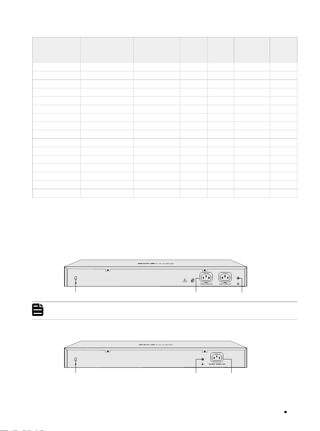
The rear panel of other models is shown as the following figure. The figure is for demonstration
purposes only. Your switch may differ in appearance from the depicted.
Power SocketGrounding TerminalKensington Security Slot

Omada Access/Access Plus/Access Max/Aggregation/Campus Managed Switch
10 Introduction
Kensington Security Slot
Secure the lock (not provided) into the security slot to prevent the device from being stolen.
Grounding Terminal
The switch already comes with lightning protection mechanism. You can also ground the switch through
the PE (Protecting Earth) cable of AC cord or with Ground Cable. For detailed lightning protection
measures, refer to the Lightning Protection Guide from: https://support.omadanetworks.com/r/1004/.
Power Socket
Connect the female connector of the power cord here, and the male connector to the AC power outlet.
Make sure that the voltage of the power supply meets the requirement of the input voltage (100–240V~
50/60 Hz).
Caution:
Please use the provided power cord.
Omada Access/Access Plus/Access Max/Aggregation/Campus Managed Switch
11Installation
Chapter 2 Installation
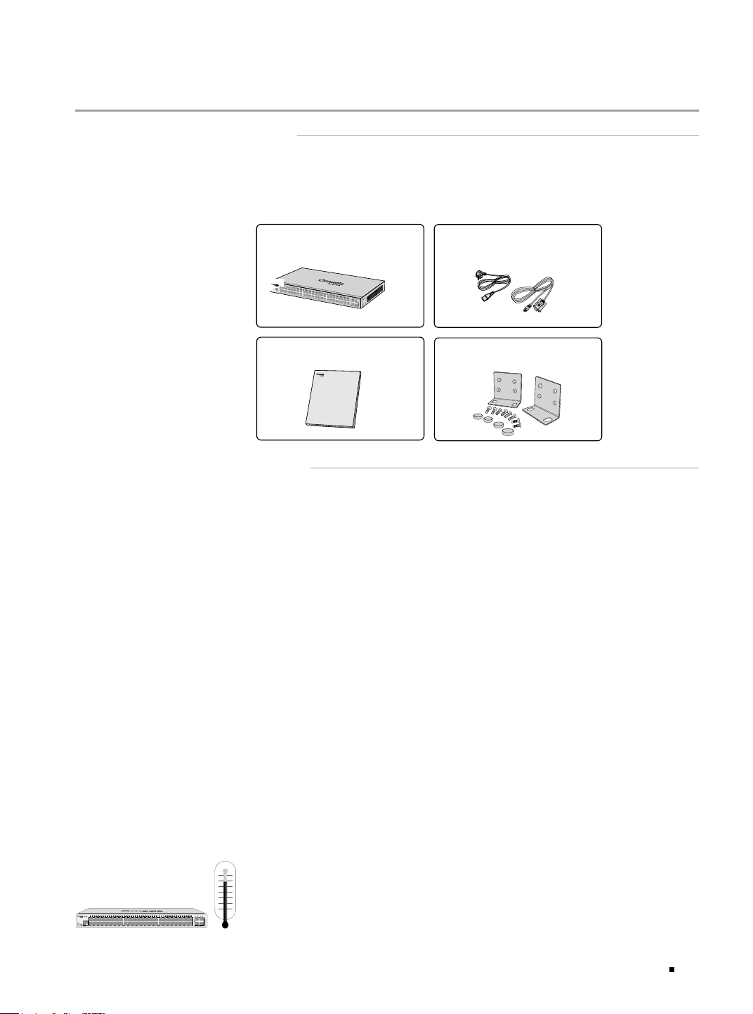
2.1 Package Contents
Make sure that the package contains the following items. Please contact your distributor, if any of
the listed items is damaged or missing. The figures are for demonstration only. The actual items may
differ in appearance and quantity from the depicted.
One Switch
Installation Guide
Installation Guide
Omada Access/Access Plus/Access Max/Aggregation/Campus
Managed Switch
Business Networking Solution
Mounting Brackets, Screws
and Rubber Feet
Power Cord and Console Cable
2.2 Safety Precautions
To avoid any device damage and bodily injury caused by improper use, you should observe the
following rules.
■
Safety Precautions
■
Keep the power off during the installation.
■
Wear an ESD-preventive wrist strap, and make sure that the wrist strap has a good skin contact and is
well grounded.
■
Use only the power cord provided with the switch.
■
Make sure that the supply voltage matches the specifications indicated on the rear panel of the
switch.
■
Ensure that the switch is installed in a well-ventilated environment and its ventilation hole is not
blocked.
■
Do not open or remove the cover of the switch.
■
Before cleaning the device, cut off the power supply. Do not clean it by the waterish cloth, and never
use any other liquid cleaning method.
■
Place the device with its bottom surface facing downwards.
■
Only instructed person or skilled person can be allowed to install, replace, or service this device.
■
Site Requirements
Temperature/Humidity
Omada Access/Access Plus/Access Max/Aggregation/Campus Managed Switch
12 Installation
Keep the equipment room at an appropriate level of temperature and humidity. Too much or too
little humidity may lead to bad insulation, leakage of electricity, mechanical property changes,
and corrosion. High temperatures may accelerate aging of the insulation materials, significantly
shortening the service life of the device. To find out the best temperature and humidity conditions
for the device, check the Appendix B Specifications.
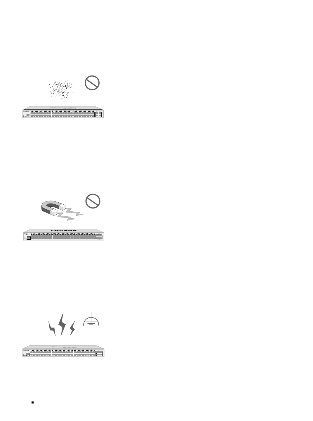
Clearness
The dust accumulated on the switch can be absorbed by static electricity and result in poor contact
of metal contact points. Some measures have been taken for the device to prevent static electricity,
but too strong static electricity can cause deadly damage to the electronic elements on the internal
circuit board. To avoid the effect of static electricity on the operation of the switch, attach much
importance to the following items:
■
Dust the device regularly, and keep the indoor air clean.
■
Keep the device well grounded and ensure that the static electricity has been transferred.
Electromagnetic Interference
Electronic elements including capacitance and inductance on the device can be affected by external
interferences, such as conducted emission by capacitance coupling, inductance coupling, and
impedance coupling. To decrease the interferences, make sure to take the following measures:
■
Use the power supply that can effectively filter interference from the power grid.
■
Keep the device far from high-frequency and strong-current devices such as radio transmitting
station.
■
Use electromagnetic shielding when necessary.
Lightning Protection
Extremely high voltage currents can be produced instantly when lightning occurs and the air in the
electric discharge path can be instantly heated up to 20,000
°C
. As this instant current is strong
Omada Access/Access Plus/Access Max/Aggregation/Campus Managed Switch
13Installation
enough to damage electronic devices, more effective lightning protection measures should be
taken.
■
Ensure that the rack and the device are well earthed.
■
Make sure the power socket has a good contact with the ground.
■
Keep a reasonable cabling system and avoid induced lightning.
■
Use the signal SPD (Surge Protective Device) when wiring outdoor.
Note:
For detailed lightning protection measures, refer to the Lightning Protection Guide from:
https://support.omadanetworks.com/r/1004/.
Installation Site
When installing the device on a rack or a flat workbench, attach much importance to the following
items:
■
Install the device with its bottom surface facing down only.
■
This equipment is not suitable for use in locations where children are likely to be present.
■
The rack or workbench is flat, stable, and sturdy enough to support the weight of 5.5 kg at least.
■
The rack or workbench has a good ventilation system. The equipment room is well ventilated.
■
The rack is well grounded. Keep the device less than 1.5 meters away from the power socket.
2.3 Installation Tools
■
Phillips screwdriver
■
ESD-preventive wrist wrap
■
Cables
Note:
These tools are not included with our product. If needed, you can purchase them separately.
2.4 Product Installation
■
Desktop Installation
To install the device on the desktop, follow the steps:
1. Set the device on a flat surface which is strong enough to support the entire weight of the device
with all fittings.
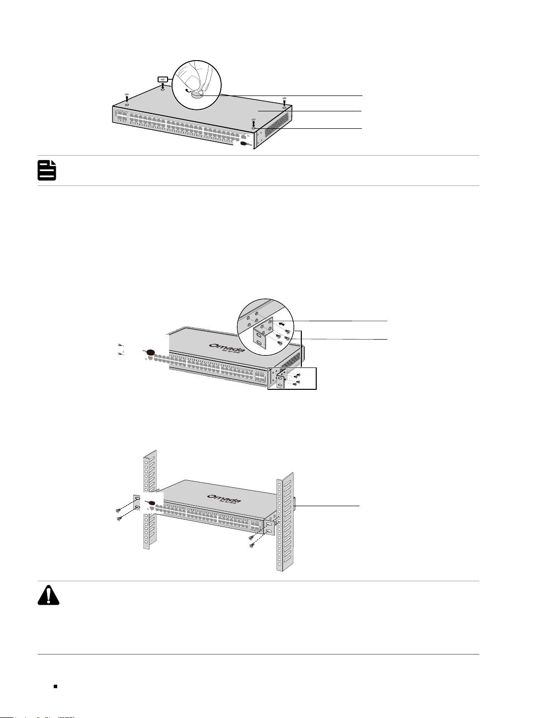
2. Remove the adhesive backing papers from the rubber feet.
3. Attach the rubber feet to the bottom of the device to prevent it from slipping when placed on a
desktop.
Omada Access/Access Plus/Access Max/Aggregation/Campus Managed Switch
14 Installation
Figure 2-1 Desktop Installation
Feet
Bottom of the Device
Notch
Note:
SG3210 is shipped with rubber feet attached. Please skip steps 2 and 3 when installing this device.
■
Rack Installation
To install the device in an EIA standard-sized, 19-inch rack, follow the instructions described below:
1. Check the efficiency of the grounding system and the stability of the rack.
2. Secure the supplied rack-mounting brackets to each side of the device with supplied screws, as
illustrated in the following figure.
Figure 2-2 Bracket Installation
Rack-mounting Bracket
Screw
3. After the brackets are attached to the device, use suitable screws (not provided) to secure the
brackets to the rack, as illustrated in the following figure.
Figure 2-3 Rack Installation
Rack
Caution:
■
Leave 5 to 10 cm gaps around the devices for air circulation.
■
Avoid placing heavy things on the device.
■
Place the device with its bottom facing downwards.
■
Mount devices in sequence from the bottom to top of the rack and ensure a certain clearance
between devices for the purpose of heat dissipation.
Omada Access/Access Plus/Access Max/Aggregation/Campus Managed Switch
15Connection
Chapter 3 Connection
3.1 Ethernet Port
Connect an Ethernet port of the switch to the computer by RJ45 cable as the following figure shows.
Figure 3-1 Connecting the RJ45 Port
RJ45 Port
RJ45 Cable
3.2 SFP/SFP+ Slot
The following figure demonstrates the connection of SFP/SFP+ slot to an SFP/SFP+ module.
Figure 3-2 Inserting the SFP/SFP+ Module
SFP/SFP+ Slot
SFP/SFP+ Module
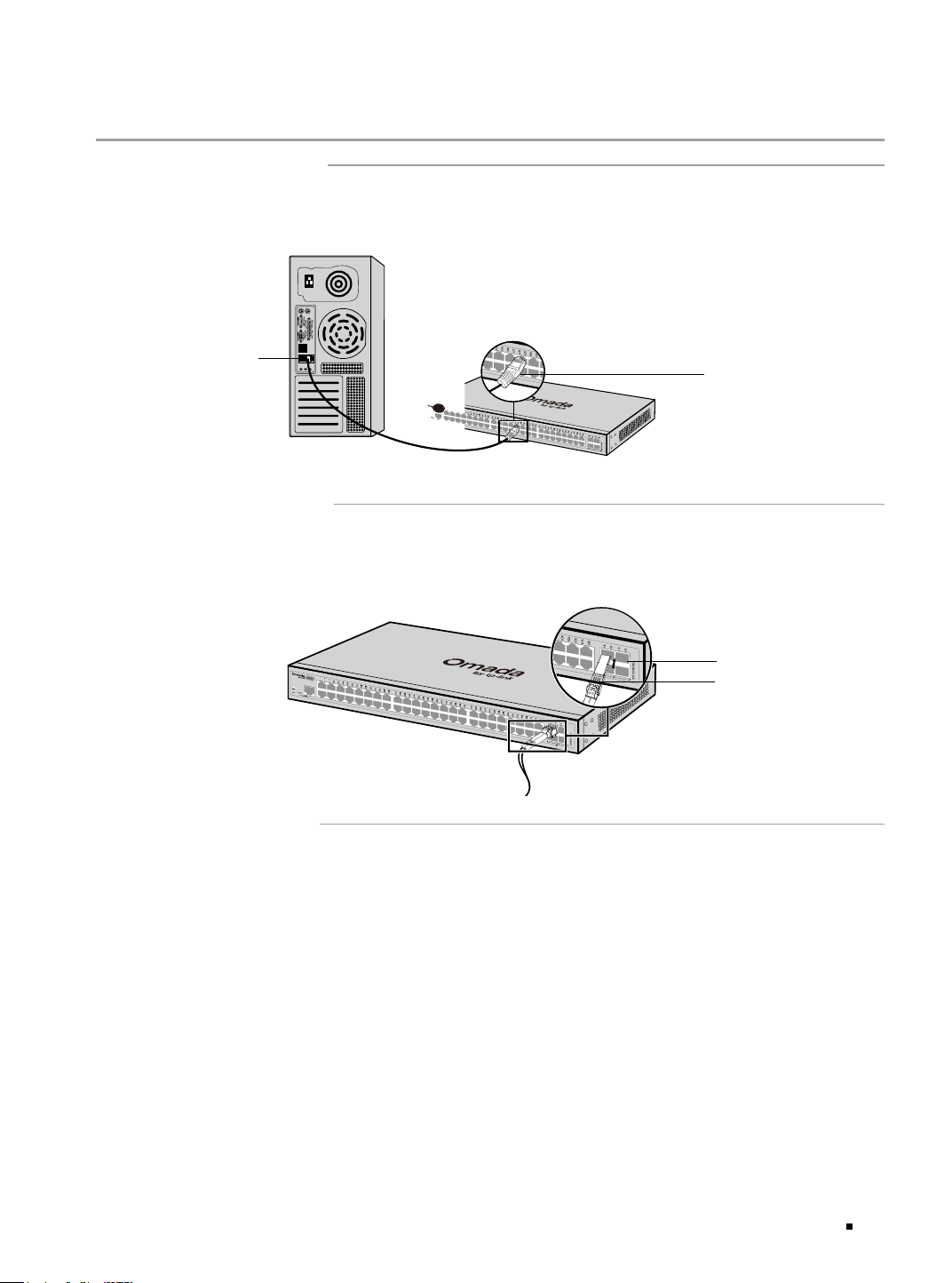
3.3 Console Port
CLI (Command Line Interface) enables you to manage the switch, thus you can load the CLI after
connecting the PCs or Terminals to the console port on the switch via a cable (an RJ45 console cable
is provided, while micro-USB/USB Type-C cable is not provided).
Connect the console (RJ45) port of the device with your computer by the console cable as the
following figure shows.
Omada Access/Access Plus/Access Max/Aggregation/Campus Managed Switch
16 Connection
Figure 3-3 Connecting the Console (RJ45) Port
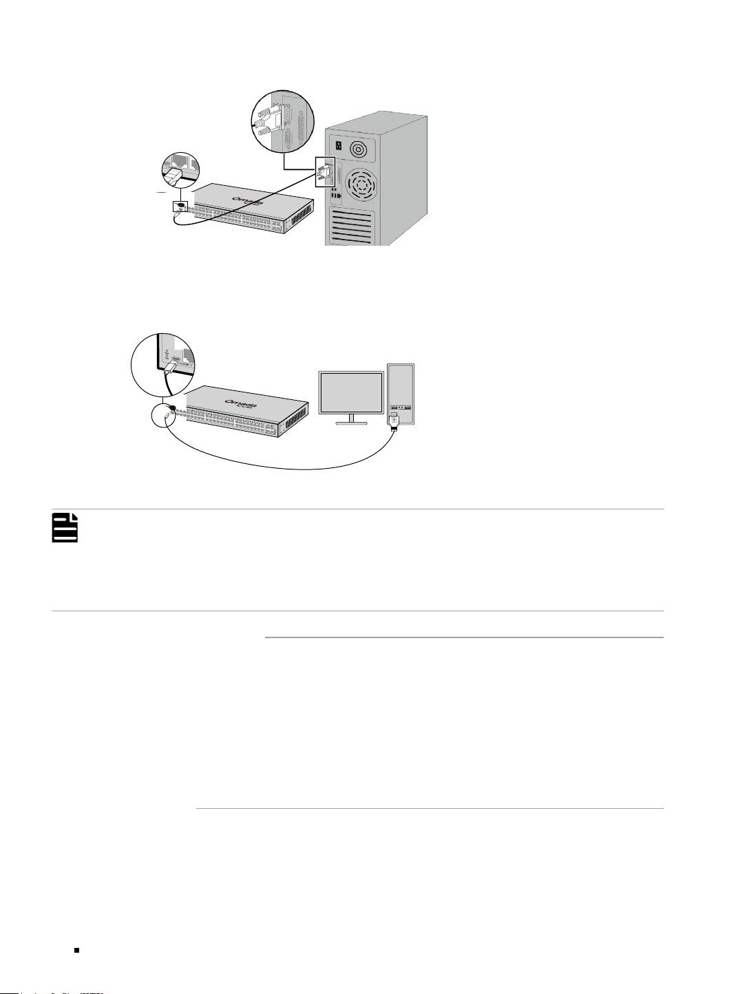
Connect the console (USB) port of the device with your computer by the USB cable (not provided) as
the following figure shows.
Figure 3-4 Connecting the Console (USB) Port
Note:
■
Console (RJ45) port and console (USB) port cannot be used concurrently. Console (USB) port takes
priority over the Console (RJ45) port.
■
The console (USB) port is hot-pluggable while the console (RJ45) port is not. Keep the device power
off when plugging the console cable into the console (RJ45) port.
■
Do not connect the console port with other ports by RJ45 cable.
3.4 Verify Installation
After completing the installation, verify the following items:
■
There should be 5 to 10 cm of clearance around the device for ventilation and make sure the air flow
is adequate.
■
The voltage of the power supply meets the requirement of the input voltage of the device.
■
The power socket, device and rack are well grounded.
■
The device is correctly connected to other network devices.
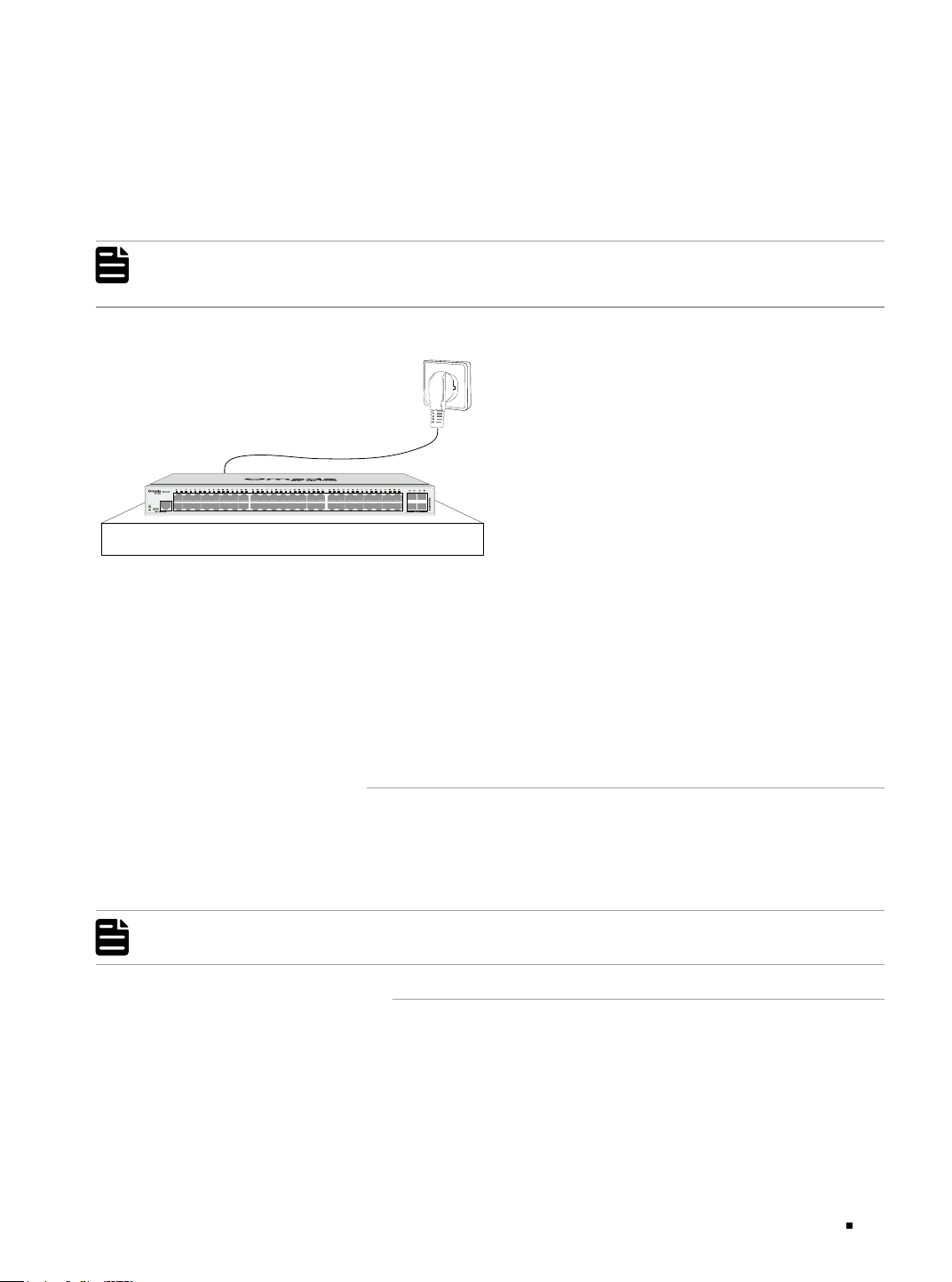
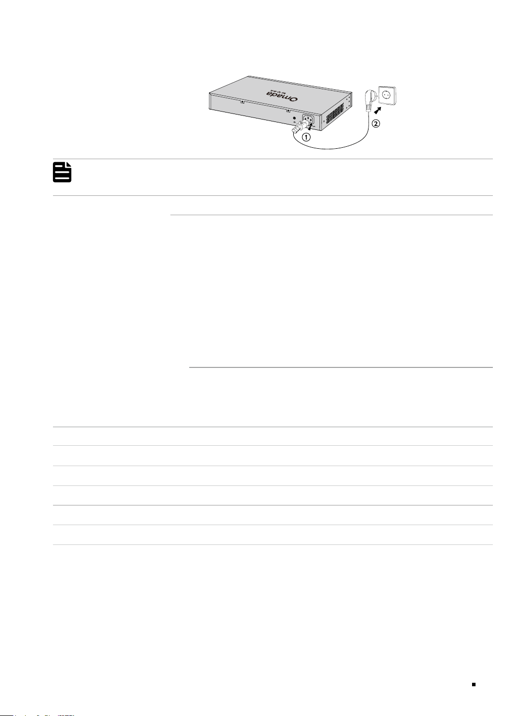
3.5 Power On
Plug the female connector of the provided power cord into the power socket of the device and plug
the positive connector into a power outlet as the following figure shows. Make sure that the voltage
of the power supply meets the requirement of the input voltage (100-240 V~ 50/60 Hz).
Omada Access/Access Plus/Access Max/Aggregation/Campus Managed Switch
17Connection
Figure 3-5 Connecting to Power Supply
Note:
The gure is to illustrate the application and principle. The provided plug and the socket in your
region may dier from the gures above.
3.6 Initialization
After the device is powered on, it begins the Power-On Self-Test. A series of tests run automatically
to ensure the device functions properly. During this time, its LED indicators will respond in the
following order:
1. The PWR LED indicator lights on all the time. The SYS LED and the LED indicators of all the ports
keep off.
2. After about one minute, the SYS LED and LED indicators of all the ports will flash momentarily and
then turn off.
3. Several seconds later, the SYS LED indicator will flash, which represents a successful initialization.
3.7 Stack Topology
With stackable design, the Campus Switches can be stacked into one stack topology for higher
reliability, larger bandwidth, and simpler networking. To build the stack topology, you need to
prepare 2-4 switches and enough 10G SFP+ modules/cables. For more details, see the table below:
Switch Compatible Model(s) Quantity
SG5428X SG5428X, SG5428XMPP, SG5452X, SG5452XMPP, SG5428XF 2-4
SG5428XMPP SG5428X, SG5428XMPP, SG5452X, SG5452XMPP, SG5428XF 2-4
SG5452X SG5428X, SG5428XMPP, SG5452X, SG5452XMPP, SG5428XF 2-4
SG5452XMPP SG5428X, SG5428XMPP, SG5452X, SG5452XMPP, SG5428XF 2-4
SG5428XF SG5428X, SG5428XMPP, SG5452X, SG5452XMPP, SG5428XF 2-4
There are three stack topology structures for different scenarios, please build the proper topology
according to your needs:
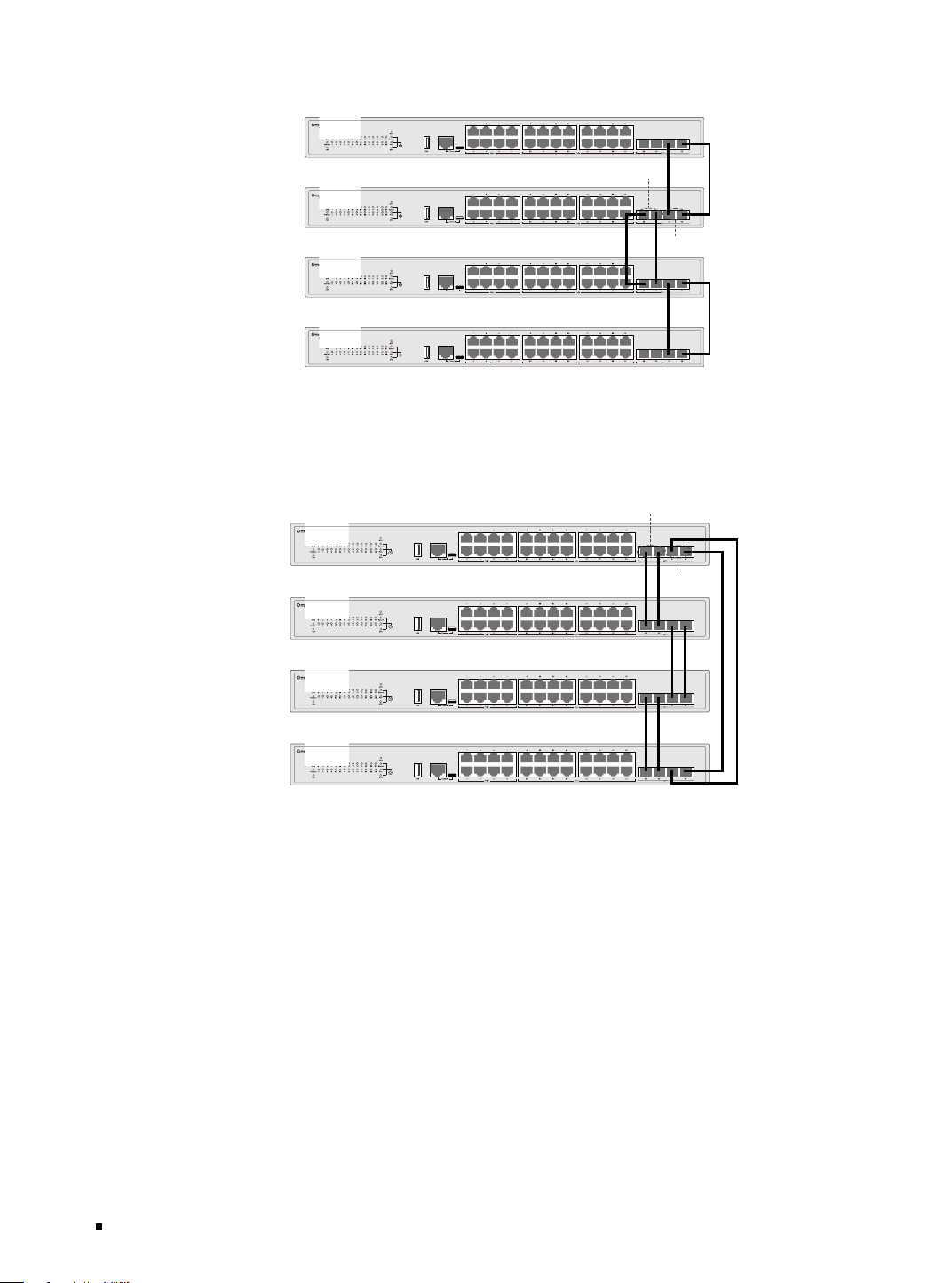
1. Chain Topology: Chain topology is relatively simple and does not require cable connection
between the first and last unit. It is suitable for long-distance stacking, but its reliability is
relatively low.
Omada Access/Access Plus/Access Max/Aggregation/Campus Managed Switch
18 Connection
Figure 3-6 Chain Topology
Stacking Port
Group 1
Stacking Port Group 2
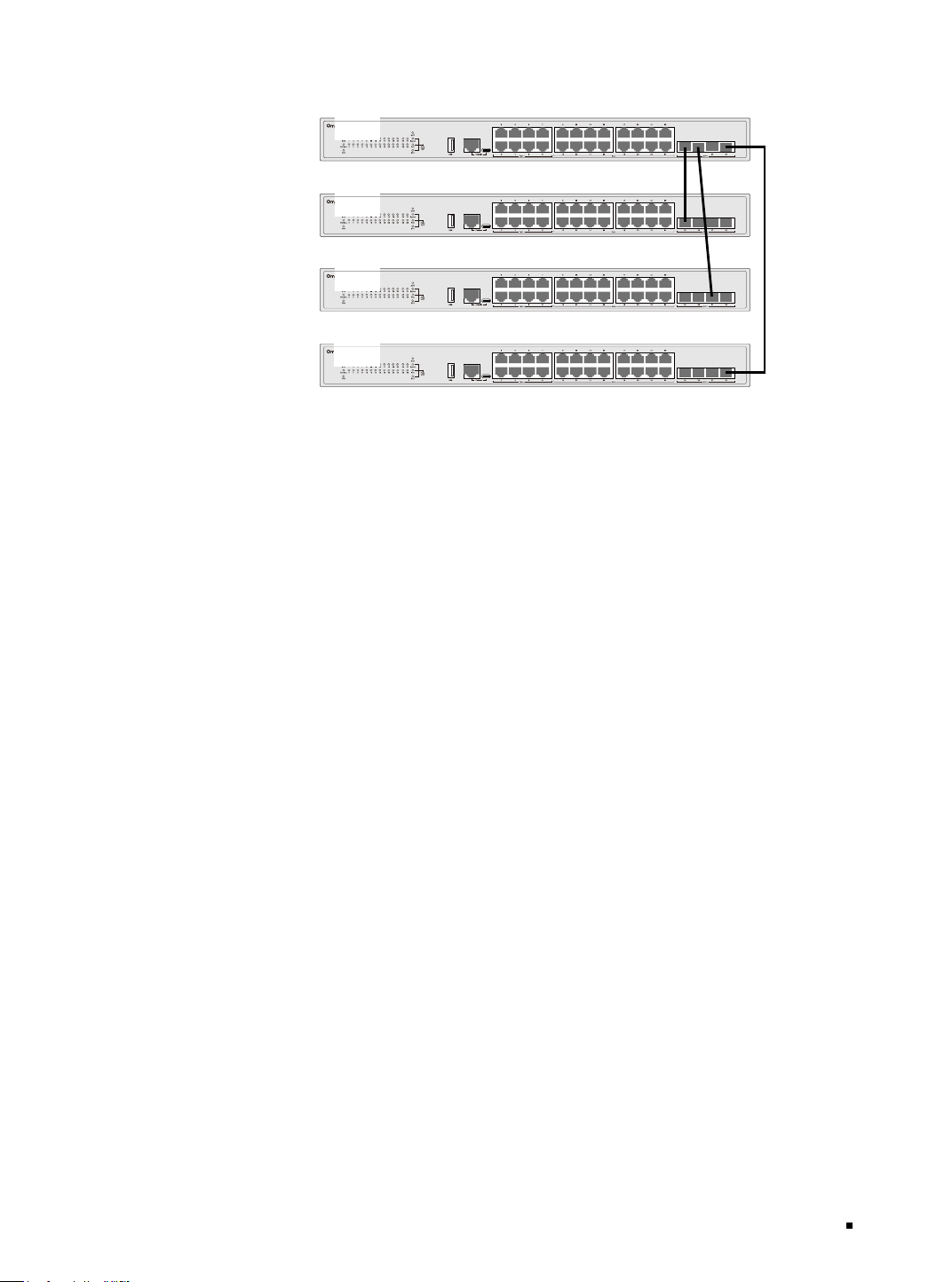
2. Ring Topology: Ring topology has higher reliability compared with the chain topology. When one
of the chains in the ring topology is disconnected, the ring topology becomes a chain topology,
but the entire stack system can still work normally. The ring topology requires cable connection
between the first and last unit, so it's not suitable for long-distance stacking.
Figure 3-7 Ring Topology
Stacking Port
Group 1
Stacking Port Group 2
3. Star Topology: Star topology connects the switches to a central main switch, therefore, it can
significantly increase the data forwarding rate between member switches while providing unified
management.
Omada Access/Access Plus/Access Max/Aggregation/Campus Managed Switch
19Connection
Figure 3-8 Star Topolog y
Note:
• Stacking port is not allowed to connect to non-stacking port, as it may affect the operation of the
device.
• Stacking ports with the same group ID are not allowed to connect to stacking ports with different
group IDs, neither to different devices.
• A stacking port group is a logical port dedicated to stacking and needs to be bound to a stacking
port. A stacking port group can be bound to one or more stacking ports to improve bandwidth and
reliability.
Omada Access/Access Plus/Access Max/Aggregation/Campus Managed Switch
20 Conguration
Chapter 4 Configuration
4.1 Conguration Overview
The switch supports two configuration options:
■
Standalone Mode: Configure and manage the switch singly.
■
Controller Mode: Configure and manage the network devices centrally. It is recommended in the
large-scale network, which consists of mass devices such as access points, switches, and gateways.
Note:
When the switch is changed from Standalone Mode to Controller Mode, congurations of the switch
will be lost. For details, refer to the related documents on the download center of our ocial website:
https://support.omadanetworks.com/product/.
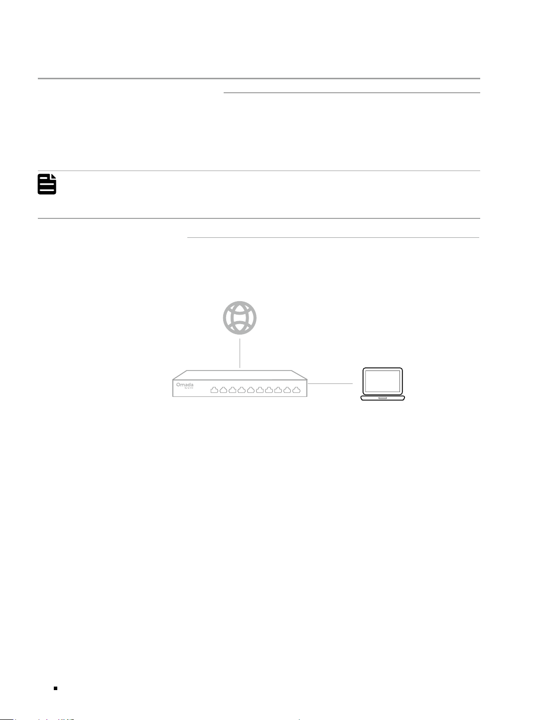
4.2 Standalone Mode
In Standalone Mode, use a computer to configure and manage the switch using GUI (Graphical User
Interface) or CLI (command-line interface).
Figure 4-1 Topology for Standalone Mode
Switch PC
■
Using the GUI
1. To access the management page of the switch, make sure the switch and computer are in the
same subnet. Open a browser and type the switch’s IP address in the address field, then press the
Enter key.
■
If the switch obtains IP address from the DHCP server (typically a gateway), find the switch’s IP
address on the DHCP server.
■
If not, use the default IP address 192.168.0.1 to launch the switch’s management page.
2. The first time you log in, set the username and password to better protect your network and
devices. After that, the system will automatically redirect you back to the login interface to
authenticate with the newly created credentials.
3. After a successful login, the main page will appear. You can click the menus on the top side and left
side to configure the corresponding functions.
For the detailed configurations, refer to the User Guide and CLI Guide. The guides can be found on
the download center of our official website: https://support.omadanetworks.com/product/.
■
Using the CLI
■
Set up a Telnet or SSH connection to access the switch via CLI.
Omada Access/Access Plus/Access Max/Aggregation/Campus Managed Switch
21Conguration
■
Use the console port to access the switch. When using the console port, start the terminal emulation
program (such as the Hyper Terminal) on the PC and configure the terminal emulation program as
follows:
Baud Rate Data Bits Parity Stop Bits Flow Control
38400 bps 8 None 1 None
For the detailed configurations, refer to the User Guide and CLI Guide. The guides can be found on
the download center of our official website: https://support.omadanetworks.com/product/.
Note:
For certain devices, you may need to change the password the rst time you log in, which will better
protect your network and devices.
4.3 Controller Mode
Controller Mode applies to the large scale network with mass devices. All devices can be centrally
configured and monitored via Omada Hardware Controller or Omada Software Controller.
Note:
Before the following congurations, make sure the switch can access the internet. When using
Omada Hardware/Software Controller, make sure the switch and the controller are in the same
subnet. Typically, the switch obtains IP address from the DHCP server. You can check the switch’s IP
address on the DHCP server.
■
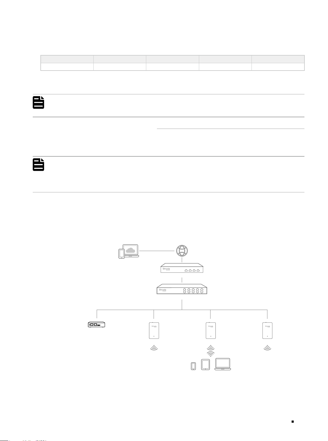
Via Omada Hardware Controller
Omada Hardware Controller is a good alternative if you have no spare PC to keep running Omada
Software Controller in the network. It needs to be purchased additionally. Follow the steps below to
configure the Omada Hardware Controller.
Figure 4-2 Manage the network via Omada Hardware Controller
Switch
Gateway
Clients
Omada Hardware Controller
AP AP AP
Omada Access/Access Plus/Access Max/Aggregation/Campus Managed Switch
22 Conguration
Note:
■
Before you start, be sure to power up and connect your devices according to the topology figure.
■
A DHCP server (typically a gateway with DHCP function enabled) is required to assign IP addresses to
the EAPs and clients in your local network.
■
Omada Controller must have network access to your Omada devices (the gateway, switch, or EAPs) in
order to find, adopt, and manage them.
1. Find the IP address of the gateway. Open the command line on your PC and enter ipconfig. In the
result list, find the Default Gateway, which is also the IP address of the gateway.
2. Launch a web browser and enter the IP address of the gateway. Log into the gateway’s web page.
Then go to Network > LAN > DHCP Client List to find the IP address of your controller according
to its MAC address.
3. Enter the IP address of the your controller in the address bar to open its web page.
4. On the Omada Controller’s web page, follow the wizard to complete the quick setup.
5. After the quick setup, the login page appears. Enter the username and password you have created
and click Log in. Then you can further configure the controller.
6. If you want to manage the devices reomotely, follow the next steps:
a. Make sure that Cloud Access is enabled on your controller. By default, Cloud Access is enabled.
Make sure that the Cloud LED is flashing slowly.
b. Launch a web browser and enter https://omada.tplinkcloud.com in the address bar. Enter your
TP-Link ID and password to log in. Click + Add Controller and choose Hardware Controller to
add your controller. Then you can further configure the controller.
For more details, refer to the Installation Guide of OC200/OC220/OC300/OC400.
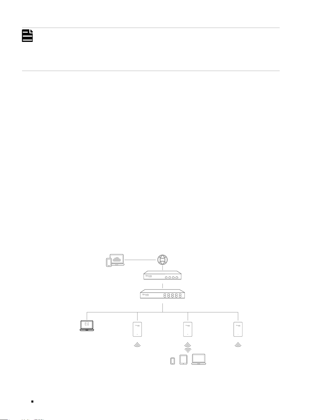
■
Via Omada Software Controller
On a PC with Windows OS or Linux OS, download the Omada Software Controller from https://
support.omadanetworks.com/product/omada-software-controller/. Then run the file and
follow the wizard to install the Omada Software Controller. Follow the steps below to configure the
Controller.
Figure 4-3 Manage the network via Omada Software Controller
Switch
Gateway
Clients
Controller
Omada Software Controller
running on the Host PC
AP AP AP

Omada Access/Access Plus/Access Max/Aggregation/Campus Managed Switch
23Conguration
1. Launch the Omada Software Controller on your PC. After the initiation process, the controller
automatically opens its web page. If not, click Launch a Browser to Manage the Network.
2. On the Omada Controller’s web page, follow the wizard to complete the quick setup.
3. After the quick setup, the login page appears. Enter the username and password you have created
and click Log in. Then you can further configure the controller.
4. If you want to manage the devices reomotely, follow the next steps:
a. Make sure that Cloud Access is enabled on your controller and your controller has been bound
with your TP-Link ID. On the Omada Controller’s web page, go to Settings > Cloud Access to
enable Cloud Access and bind your TP-Link ID. If you have set it up in the quick setup, skip this
step.
b. Launch a web browser and enter https://omada.tplinkcloud.com in the address bar. Enter your
TP-Link ID and password to log in. A list of controllers that have been bound with your TP-Link ID
will appear. Then you can click Launch to further configure the controller.
Note:
To manage your devices, Omada Software Controller needs to keep running on your computer.
*
Omada App
With the Omada app, you can also manage your controller at a local site or a remote site via your
mobile device.
For the detailed configurations, refer to the User Guide of the controller. The guide can be found on
the download center of our official website: https://support.omadanetworks.com/product/.

Omada Access/Access Plus/Access Max/Aggregation/Campus Managed Switch
24 Appendix A Troubleshooting
Appendix A Troubleshooting
Q1. What could I do if I forgot the username and password of the switch?
1. Connect the console port of the PC to the console port of the switch and open a terminal
emulation program.
2. Power off and restart the switch. Perform the action indicated by the terminal emulation program
to reach the bootUtil menu. The action differs from product to product. Possible actions are
listed below:
• Press any key to stop autoboot.
• Press CTRL-B to reach the bootUtil menu.
3. The bootUtil menu will be shown. Enter the number 6 to select the “Password recovery” option
and enter Y to delete all the users and passwords. Then you can reset the username and
password.
Q2. Why does the PWR LED work abnormally?
The PWR LED should be lit up when the power system works normally. If the PWR LED worked
abnormally, take the following steps:
1. Make sure that the power cable is connected properly, and the power contact is normal.
2. Make sure the voltage of the power supply meets the requirement of the input voltage of the
switch.
Q3. What should I do if I cannot access the web management page?
Try the following:
1. Check every port LED on the switch and make sure the Ethernet cable is connected properly.
2. Try another port on the switch and make sure the Ethernet cable is suitable and works normally.
3. Power off the switch and, after a while, power it on again.
4. Make sure the IP address of your PC is set within the subnet of the switch.
5. If you still cannot access the configuration page, reset the switch to its factory defaults. Then
the IP address of your PC should be set as 192.168.0.x ("x" is any number from 2 to 254) and
subnet mask as 255.255.255.0.
Q4. Why is the terminal emulation program not displaying correctly?
Try the following:
1. Make sure the power supply is normal and the console cable is properly connected.
2. Check if the console cable is the right type.
3. Ensure the parameters of the terminal emulation program are correct: configure Bits per second
as 38400, Data bits as 8, Parity as None, Stop bits as 1, and Flow control as None.

Omada Access/Access Plus/Access Max/Aggregation/Campus Managed Switch
25Appendix B Specications
Appendix B Specifications
Specifications for Switches with RJ45 Ports and SFP/SFP+ Slots
Item Content
Standards
IEEE802.3, IEEE802.3i, IEEE802.3u, IEEE802.3ab, IEEE802.3ad, IEEE802.3z,
IEEE802.3x, IEEE802.1p, IEEE802.1q, IEEE802.1x, IEEE802.1d, IEEE802.1s,
IEEE802.1w, IEEE802.1ab
IEEE802.3af/at
(For SG3428MP, SG3428XMP, SG3428XMPP, SG5428XMPP, SG5452XMPP)
IEEE802.3bt
(For SG3428XMPP, SG5428XMPP, SG5452XMPP)
IEEE 802.3ae
(Except SG3210, SG3428)
IEEE 802.3an, IEEE 802.3bz
(For SX3832)
Transmission
Medium
10BASE-T: 2-pair UTP/STP of Cat. 3,4,5 (maximum 100 m)
(Except SG3428XF, SG5428XF)
100BASE-TX: 2-pair UTP/STP of Cat. 5 or above (maximum 100 m)
1000BASE-T: 4-pair UTP/STP of Cat. 5e or above (maximum 100 m)
2.5GBASE-T: 4-pair UTP/STP of Cat. 5e or above (maximum 100 m)
(For SX3832)
5GBASE-T: 4-pair UTP/STP of Cat. 5e or above (maximum 100 m)
(For SX3832)
10GBASE-T: 4-pair UTP of Cat 6 (maximum 55 m) or STP of Cat 6, 6a, 7 (maximum
100 m)
(For SX3832)
100BASE-FX/LX10/BX10: MMF, SMF
(For SG3210, SG3428XF, SG5428XF)
1000BASE-SX/LX/LX10/BX10: MMF, SMF
10GBASE-SR/LR: MMF, SMF
(Except SG3210, SG3428, SG3428MP)
10GSFP+CU SFP+ Direct Attach Cable (SM5220-1M, SM5220-3M)
(Except SG3210,
SG3428, SG3428MP)
LED
SG3210/SG3428: PWR, SYS, Speed, SFP
SG3428X/SG3452X: PWR, SYS, Speed, SFP+
SG3428MP: PWR, SYS, PoE Max, FAN, Speed, PoE, Port 1-24, SFP
SG3428XMP/SG3428XMPP: PWR, SYS, PoE Max, FAN, Speed, PoE, Port 1-24, SFP+
SX3832: PWR, SYS, FAN, Speed, SFP+
SG3428XF: PWR1, PWR2, SYS, FAN, Speed, SFP+
SG5428X: PWR, SYS, MST, Speed, STK, Port 1-24, SFP+
SG5428XMPP: PWR, SYS, PoE Max, FAN, MST, Speed, PoE, STK, Port 1-24, SFP+
SG5452X: PWR, SYS, MST, Speed, STK, Port 1-48, SFP+
SG5452XMPP: PWR, SYS, PoE Max, FAN, MST, Speed, PoE, STK, Port 1-48, SFP+
SG5428XF: PWR1, PWR2, SYS, FAN, MST, Speed, STK, Port 1-24, SFP+

Omada Access/Access Plus/Access Max/Aggregation/Campus Managed Switch
26 Appendix B Specications
Operating
Temperature
SG5452XMPP:
-5 °C to 40 °C (23 °F to 104 °F)
SG3428, SG3428X, SG3452X, SG3428MP, SG3428XMP, SG3428XMPP, SG3428XF,
SG5428X, SG5428XMPP, SG5452X, SG5428XF:
-5 °C to 45 °C (23 °F to 113 °F)
SG3210, SX3832:
-5 °C to 50 °C (23 °F to 122 °F)
Storage
Temperature
-40 °C to 70 °C (-40 °F to 158 °F)
Operating
Humidity
10% to 90% RH Non-condensing
Storage
Humidity
5% to 90% RH Non-condensing
Specifications for Switches with Full SFP+ Slots
Item Content
Standards IEEE802.3, IEEE802.3z, IEEE 802.3ae, IEEE 802.3x
Transmission
Medium
1000BASE-SX/LX/LX10/BX10: MMF, SMF
10GBASE-SR/LR: MMF, SMF
LED
SX3016F: PWR1, PWR2, SYS, FAN, Port 1–16
SX3032F: PWR1, PWR2, SYS, FAN, Port 1–32
Operating
Temperature
-5 °C to 45 °C (23 °F to 113 °F)
Storage
Temperature
-40 °C to 70 °C (-40 °F to 158 °F)
Operating
Humidity
10% to 90% RH Non-condensing
Storage
Humidity
5% to 90% RH Non-condensing
CE Mark Warning
This is a class A product. In a domestic environment, this product may cause radio interference, in
which case the user may be required to take adequate measures.
EU Declaration of Conformity
TP-Link hereby declares that the switch is in compliance with the essential requirements and other
relevant provisions of directives 2014/30/EU, 2014/35/EU, 2011/65/EU and (EU)2015/863.
The original EU Declaration of Conformity may be found at https://www.tp-link.com/en/support/ce/
UK Declaration of Conformity
TP-Link hereby declares that the switch is in compliance with the essential requirements and other
relevant provisions of the Electromagnetic Compatibility Regulations 2016 and Electrical Equipment
(Safety) Regulations 2016.
The original UK Declaration of Conformity may be found at https://www.tp-link.com/support/ukca/
Продукт сертифіковано згідно с правилами системи УкрСЕПРО на відповідність вимогам
нормативних документів та вимогам, що передбачені чинними законодавчими актами України.
CAUTION:
Double pole, neutral fusing.
Disconnect mainsbefore servicing.
Safety Information
• Keep the device away from water, fire, humidity or hot environments.
• Do not attempt to disassemble, repair, or modify the device.If you need service, please contact us.
• Place the device with its bottom surface downward.
• The plug on the power supply cord is used as the disconnect device, the socket-outlet shall be
easily accessible.
• Plug the product into the wall outlets with earthing connection through the power supply cord
or plug.
• The socket-outlet shall be installed near the equipment and shall be easily accessible.
• The PoE ports shall not be used to charge lithium batteries or devices supplied by lithium
batteries.
© 2025 TP-Link 7100002388 REV1.2.0
For technical support, user guides and other information, please visit https://support.omadanetworks.com/, or simply
scan the QR code.
• In Denmark: “Apparatets stikprop skal tilsluttes en stikkontakt med jord som giver forbindelse
til stikproppens jord.”;
In Finland: "Laite on liitettävä suojakoskettimilla varustettuun pistorasiaan" ;
In Norway: “Apparatet må tilkoples jordet stikkontakt” ;
In Sweden: “Apparaten skall anslutas till jordat uttag” .
• Operating temperature:
SG5452XMPP:
-5 °C to 40 °C (23 °F to 104 °F)
SG3428, SG3428X, SG3452X, SG3428MP, SG3428XMP, SG3428XMPP, SG3428XF, SX3016F,
SX3032F, SG5428X, SG5428XMPP, SG5452X, SG5428XF:
-5 °C to 45 °C (23 °F to 113 °F)
SG3210, SX3832:
-5 °C to 50 °C (23 °F to 122 °F)
• 運作溫度:
SG5452XMPP:
-5°C至40°C(23°F至104°F)
SG3428,SG3428X,SG3452X,SG3428MP,SG3428XMP,SG3428XMPP,SG3428XF,SX3016F,
SX3032F,SG5428X,SG5428XMPP,SG5452X,SG5428XF:
-5°C至45°C(23°F至113°F)
SG3210,SX3832:
-5°C至50°C(23°F至122°F)
This equipment is not suitable for use in locations
where children are likely to be present.
此設備不適用於孩童可能出現的區域
Please read and follow the above safety information when operating the device. We cannot
guarantee that no accidents or damage will occur due to improper use of the device. Please use this
product with care and operate at your own risk.