Quick Installation Guide
Wireless Access Point
Setup with videos
Visit https://www.tp-link.com/support/setup-video/ or scan the QR code to search for
the setup video of your product model.
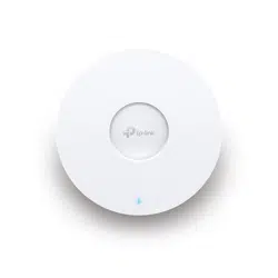
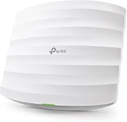
Note: For simplicity, we will take EAP650 V1 for example throughout the Guide. The image may dier from the actual product.
Hardware Overview
1
On:
Working normally/Initializing.
Off:
Working abnormally/Power o/LED is turned o.
Flashing:
Initialization
: The LED ashes twice after initialization is completed.
Upgrade
: The LED ashes once per second while upgrading.
Reset
: The LED ashes quickly during the reset. The EAP will then reboot.
Isolated
: The LED ashes slowly. The EAP is in the isolated state.
Locate
: When the Locate feature is activated in the Omada controller, the LED ashes quickly to locate and
identify the device. The LED will ash for 10 minutes, or you can disable the feature manually to stop it ashing.
LED Indicator
RESET
With the device powered on, press and hold the button for about 5 seconds until the LED flashes quickly. Then release the
button. The device will restore to factory default settings.
The port is used to connect to a router or a switch to transmit data, or to a PSE (Power Sourcing Equipment), such as a PoE switch,
for both data transmission and Power over Ethernet (PoE) through Ethernet cable. The port supports transmission speed of
10/100/1000 Mbps.
Ethernet Port: ETH (PoE)
Plug one end of the provided power adapter to this port and the other end to a standard electrical wall outlet to power the EAP.
Please use the power adapter provided in the package.
Power Port
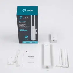
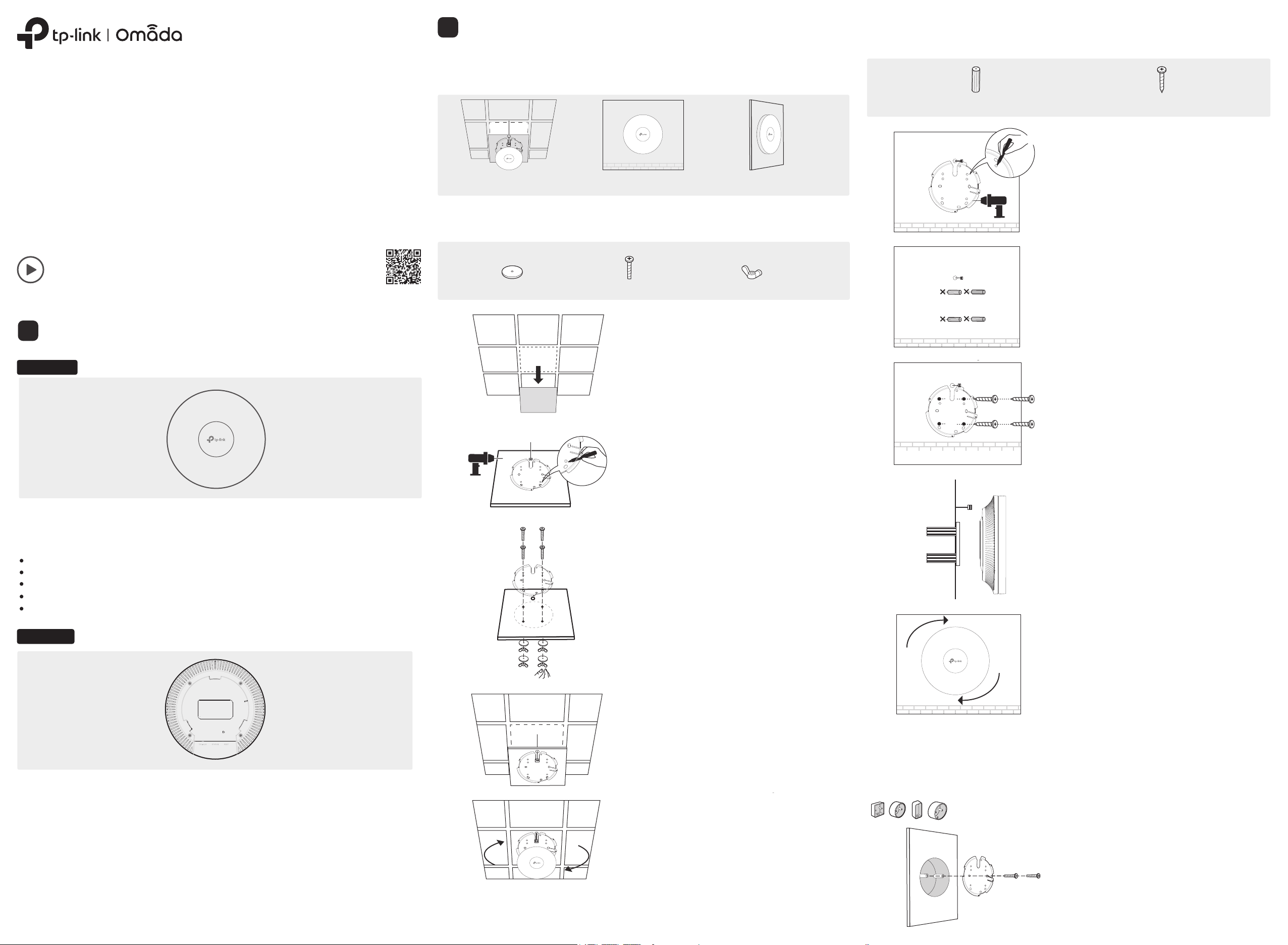
M3×20 Self-tapping Screws (Qty.4)
M3×28 Plastic Wall Anchors (Qty.4)
1
Remove the ceiling tile.
Note: Make sure that the ceiling tile is larger than the EAP.
Wing Nuts (Qty.4)Washers (Qty.4) M3×30 Pan-head Screws (Qty.4)
The EAP can be mounted to the ceiling, the wall, or in a junction box, using the screws in the package.
Choose the appropriate mounting and installation steps below.
Note: This product requires heat dissipation through the metal bracket during use, please be careful not
to touch the metal bracket in the heat dissipation.
Hardware Installation
2
2
Insert the plastic wall anchors into the 6 mm
diameter holes.
4
Connect the Ethernet cable to the Ethernet port on
the EAP.
Front Panel
Rear Panel
Option 2: Wall Mounting
Option 1: Ceiling Mounting
Option 2: Wall Mounting
5
Connect the Ethernet cable to the Ethernet port.
Please pay attention to the triangle sign. Attach the
EAP to the mounting bracket, then rotate it until it
locks into place, as shown on the left.
2
Place the mounting bracket in the center of the
ceiling tile. Mark four positions for the screw
holes and a location for the Ethernet cable hole.
Drill four 4 mm (5/32 in) diameter holes for the
screws and a 25 mm (63/64 in) diameter hole for
the Ethernet cable at the marked positions.
Drill Hole for Ethernet cable
X4
3
Secure the mounting bracket to the ceiling tile
using four M3x30 pan-head screws, washers, and
wing nuts, as shown on the left.
5
Attach the EAP to the mounting bracket by rotating
it until it locks into place, as shown on the left.
Option 3: Junction Box Mounting
4
Feed the Ethernet cable through the hole and set
the ceiling tile back into place.
Prepare the cables and the junction box in advance. Ensure that the mounting holes align to your
junction box.
*Compatible wall junctions:
Route the cables through the square cable hole on
the mounting bracket, and secure the mounting
bracket to the junction box using screws. Then
follow Step 4 and Step 5 of Option 2 to complete
the installation.
3
Secure the mounting bracket to the wall by driving
the self-tapping screws into the anchors. Make
sure that the shoulders of the mounting bracket are
on the outside.
1
If your Ethernet cable feeds through the wall,
position the mounting bracket below the cable
hole. Mark four positions for the screw holes and
drill four 6 mm (15/64 in) diameter holes at the
marked positions.
X4
Option 1: Ceiling Mounting
Option 3: Junction Box Mounting

©2022 TP-Link 7106509531 REV1.0.1
The products of TP-Link partly contain software code developed by third parties, including software code
subject to the GNU General Public License (“GPL”). As applicable, the terms of the GPL and any information on
obtaining access to the respective GPL Code used in TP-Link products are available to you in
GPL-Code-Centre under (https://www.tp-link.com/en/support/gpl/). The respective programs are distributed
WITHOUT ANY WARRANTY and are subject to the copyrights of one or more authors. For details, see the GPL
Code and other terms of the GPL.
Choose from the following methods to set up your EAPs:
The EAP can be powered via a power adapter or a PSE device (such as a PoE switch) which
complies with LPS or PS2 standard.
Method 1: Standalone Mode
Option1: Via PoE Switch (Compliant with 802.3at)
Option2: Via Power Adapter
Note:
Via Omada App
Via Omada App
1. Connect wirelessly by using the default SSID (format: TP-Link_2.4GHz/5GHz_XXXXXX) printed
on the label at the bottom of the product.
2. Launch a web browser and enter http://tplinkeap.net
in the address bar. Use admin for both
Username and Password to log in.
3. Set up a new Username and Password for secure management purpose. Modify the wireless
parameters and reconnect your wireless devices to the new wireless network.
To configure other EAPs, connect your device to the EAP by the coresponding default SSID and
repeat the steps listed above. You can configure some basic functions in Standalone Mode. If you
want to configure advanced functions, use Controller Mode.
1. Download the TP-Link Omada App on your mobile device. It can be downloaded from App Store or
Google Play:
2. Connect your mobile device to the EAP by using the default SSID (format:
TP-Link_2.4GHz/5GHz_XXXXXX) printed on the label at the bottom of the product.
3. Open the Omada App, and wait for the EAP to appear on the Standalone APs page. Tap on the
EAP you want to congure.
The Omada App is designed to help you quickly configure the common settings. If you want to
configure advanced settings, use the web page of your EAP or use Controller Mode.
Via Web Browser
Method 2: Controller Mode
For the detailed configurations, refer to the User Guide of the controller and EAPs. The guides can be found
on the download center of our official website: https://www.tp-link.com/support/download/.
Connect an Ethernet cable from the PoE switch (compliant with 802.3at ) to the Ethernet port.
Note: EAP610 V3 is also compliant with 802.3af.
Plug one end of the provided power adapter into the power port of the EAP and the other end to a
standard electrical wall outlet.
Note: Power adapter is not included in the package contents of EAP653.
Power Supply
3
PoE Switch (Compliant with 802.3at)
Switch
Power Adapter
Software Conguration
4
Internet
Clients
Router
EAP
EAP
Scan for Omada App Download Omada App
or
For technical support, the user guide and other information,
please visit https://www.tp-link.com/support, or simply scan the QR code.
If you have any suggestions or needs on the product guides,
welcome to email techwriter@tp-link.com.cn.
To ask questions, find answers, and communicate with TP-Link users or engineers,
please visit https://community.tp-link.com to join TP-Link Community.
Safety Information
Keep the device away from water, re, humidity or hot environments.
Do not attempt to disassemble, repair, or modify the device. If you
need service, please contact us.
Do not use the device where wireless devices are not allowed.
Do not use damaged charger or USB cable to charge the device.
Do not use any other chargers than those recommended.
Adapter shall be installed near the equipment and shall be easily accessible.
1. Download the TP-Link Omada App on your mobile device. It can be downloaded from App Store or
Google Play:
Scan for Omada App Download Omada App
or
Local Management
2. Launch your Omada App and configure the controller at a local site or remote site.
1. Open the Omada Controller’s web page.
3. After the quick setup, the login page appears. Enter the username and password you have created
and click Log in. Then you can further configure the controller.
4. (For Remote Management) You can remotely access and manage your controller via Omada
Cloud Service.
2. On the Omada Controller’s web page, follow the wizard to complete the quick setup.
a. Connect your mobile device to the EAP by using the default SSID (format:
TP-Link_2.4GHz/5GHz_XXXXXX) printed on the label at the bottom of the product.
b. Launch Omada App and go to Local Access, tap the
+ button on the upper-right corner to add
the controller. Then you can further congure the controller.
b. Launch a web browser and enter https://omada.tplinkcloud.com in the address bar. Enter
your TP-Link ID and password to log in. A list of controllers that have been bound with your
TP-Link ID will appear. Then you can click Launch to further configure the controller.
Switch
Router
Clients
Omada Hardware Controller EAP EAP EAP
(OC200/OC300)
Switch
Router
Clients
EAP EAP EAP
Controller
Omada Software Controller
running on the Host PC
To configure and manage EAPs separately (Convenient for a small network with only a few devices)
Method 1: Standalone Mode
Before you start, be sure to power up and connect your devices according to the topology figure.
A DHCP server (typically a router with DHCP function enabled) is required to assign IP addresses
to the EAPs and clients in your local network.
Note:
Before you start, be sure to power up and connect your devices according to the topology figure.
A DHCP server (typically a router with DHCP function enabled) is required to assign IP addresses
to the EAPs and clients in your local network.
Omada Controller must have network access to your Omada devices (the router, switch, and
EAPs) in order to find, adopt, and manage them.
To configure and manage EAPs in batches on a central platform, namely Omada Controller.
Method 2: Controller Mode
Choose from the following two types of Omada Controller:
On a PC with Windows OS or Linux OS, download the Omada Software Controller from
https://www.tp-link.com/support/download/omada-software-controller/. Then run the file and
follow the wizard to install and launch the Omada Software Controller.
To manage your devices, Omada Software Controller needs to keep running on your computer.
Type 1: Omada Software Controller
Omada Hardware Controller (OC200/OC300) is a good alternative if you have no spare PC to keep
running Omada Software Controller in the network. It needs to be purchased additionally.
For more details, refer to the Installation Guide of OC200/OC300.
Type 2: Omada Hardware Controller (OC200/OC300)
a. Make sure that Cloud Access is enabled on your controller and your controller has been
bound with your TP-Link ID.
b. Launch Omada App and log in with your TP-Link ID. Then go to Cloud Access. A list of
controllers that have been bound with your TP-Link ID will appear. Then you can further
configure the controller.
a. You need rst nd the IP address of the router. Open the command line on your PC and enter
ipconfig. In the result list, find the Default Gateway, which is also the IP address of the router.
c. Enter the IP address of the your controller in the address bar to open its web page.
b. Launch a web browser and enter the IP address of the router. Log into the router’s web page,
and both the username and password are admin by default. Then go to Network > LAN >
DHCP Client List to find the IP address of your controller according to its MAC address.
Remote Management
Via Web Browser
Launch the Omada Software Controller on your PC. After the initiation process, the controller
automatically opens its web page. If not, click Launch a Browser to Manage the Network.
As Omada Hardware Controller gets its IP address from the DHCP server of the router, we don’t
know its IP address explicitly. However, we can nd it out on the router’s DHCP client list.
For Omada Hardware Controller
Note: Before you start, make sure that both your controller and mobile device can access the
internet.
Note: Before you start, make sure that both your controller and your PC can access the internet.
For Omada Software Controller
For Omada Software Controller
a. Make sure that Cloud Access is enabled on your controller and your controller has been
bound with your TP-Link ID. On the Omada Controller’s web page, go to Settings > Cloud
Access to enable Cloud Access and bind your TP-Link ID. If you have set it up in the quick
setup, skip this step.
For Omada Software Controller
b. Launch a web browser and enter https://omada.tplinkcloud.com in the address bar. Enter
your TP-Link ID and password to log in. Click + Add Controller and choose Hardware
Controller to add your controller. Then you can further configure the controller.
a. Make sure that Cloud Access is enabled on your controller. By default, Cloud Access is
enabled. Make sure that the Cloud LED is flashing slowly.
For Omada Hardware Controller
a. Make sure that Cloud Access is enabled on your controller. By default, Cloud Access is
enabled. Make sure that the Cloud LED is flashing slowly.
b. Launch Omada App and log in with your TP-Link ID. Then go to Cloud Access. Tap the +
button on the upper-right to add your controller. Then you can further configure the
controller.
For Omada Hardware Controller