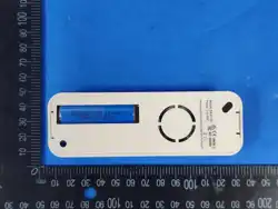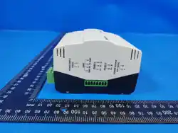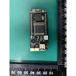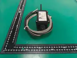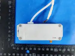
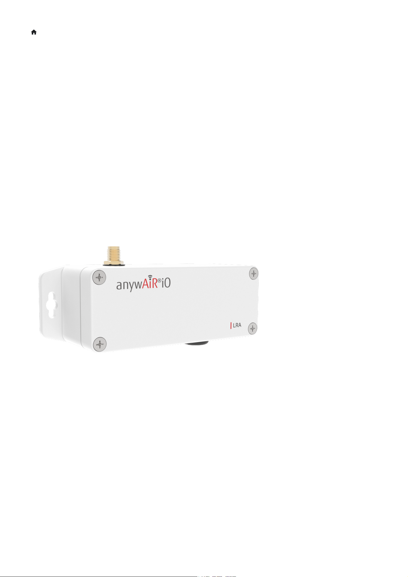
LoraLink UART Long Range Adaptor (LRA) User Manual
UART Long Range Adaptor (LRA) User
Manual
1. About Product
1.1. Product Overview
The UART Long Range Adaptor (LRA) is anywAiR iO’s wireless (LoRa®) Long Range Adaptor (LRA) controller. Designed to
interface directly with compatible RAC/PAC and VRF Air Conditioning units in a small package, reducing the installation
time and bypassing the AT command interface.
LoRa® wireless IoT technology offers a long transmission range, low power consumption, and is less susceptible to object
interference than other wireless technologies. This ensures seamless control integration for a range of applications.
1.2. Architecture
Long Range Adaptor (LRA): Acts as the communication device, interfacing with compatible RAC/PAC and VRF Air
Conditioning units via the UART protocal. It manages data transmission to and from the central anywAiR iO gateway.
anywAiR iO Gateway: Serves as the central node, managing communication from multiple Long Range Adaptor (LRA)
devices and distributing data as needed.
Control: The Long Range Adaptor (LRA) device directly manages data exchange with compatible Air Conditioning units
using their specific UART protocol.
1.3. Product Features
Operation Control: Enable the unit on and off.
Mode Control: Switch between cool, heat, dry, auto, and fan modes.
Temperature Setpoint Control: Adjust heating/cooling temperature setpoint.
Cooling setpoint 18 to 30 degrees Celsius
Heating setpoint 16-18 to 30 degrees Celsius (low limit model dependent)
Fan Speed Control: Control fan speed (model dependent).
Louvre Direction Control: Adjust vertical and horizontal louvre position and louvre swing operation (model dependent).
Economy Control: Enable and disable the unit's economy mode.
Return Air Temperature Monitoring: Monitor the return air temperature.
Error Status Reporting: Retrieve the error status and error code.
2. Hardware Overview
2.1. Packing List
Installation & User Manual.
UART Long Range Adaptor (LRA) Device
LoRa Antenna.
PAP-04V-S power/communication cable.
Mounting screws/velcro tape.
Insert Packing list images
2.2. Product Dimensions
Height: 36 mm / 1.42 inches
Width: 110 mm / 4.33 inches
Depth: 35 mm / 1.38 inches
Enclosure Light Grey Polycarbonate, IP68 Rated
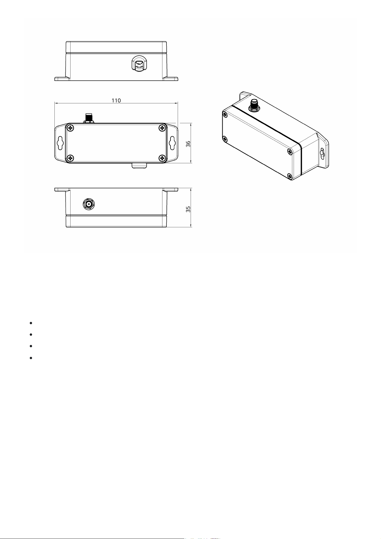
2.3. Product Component Breakdown
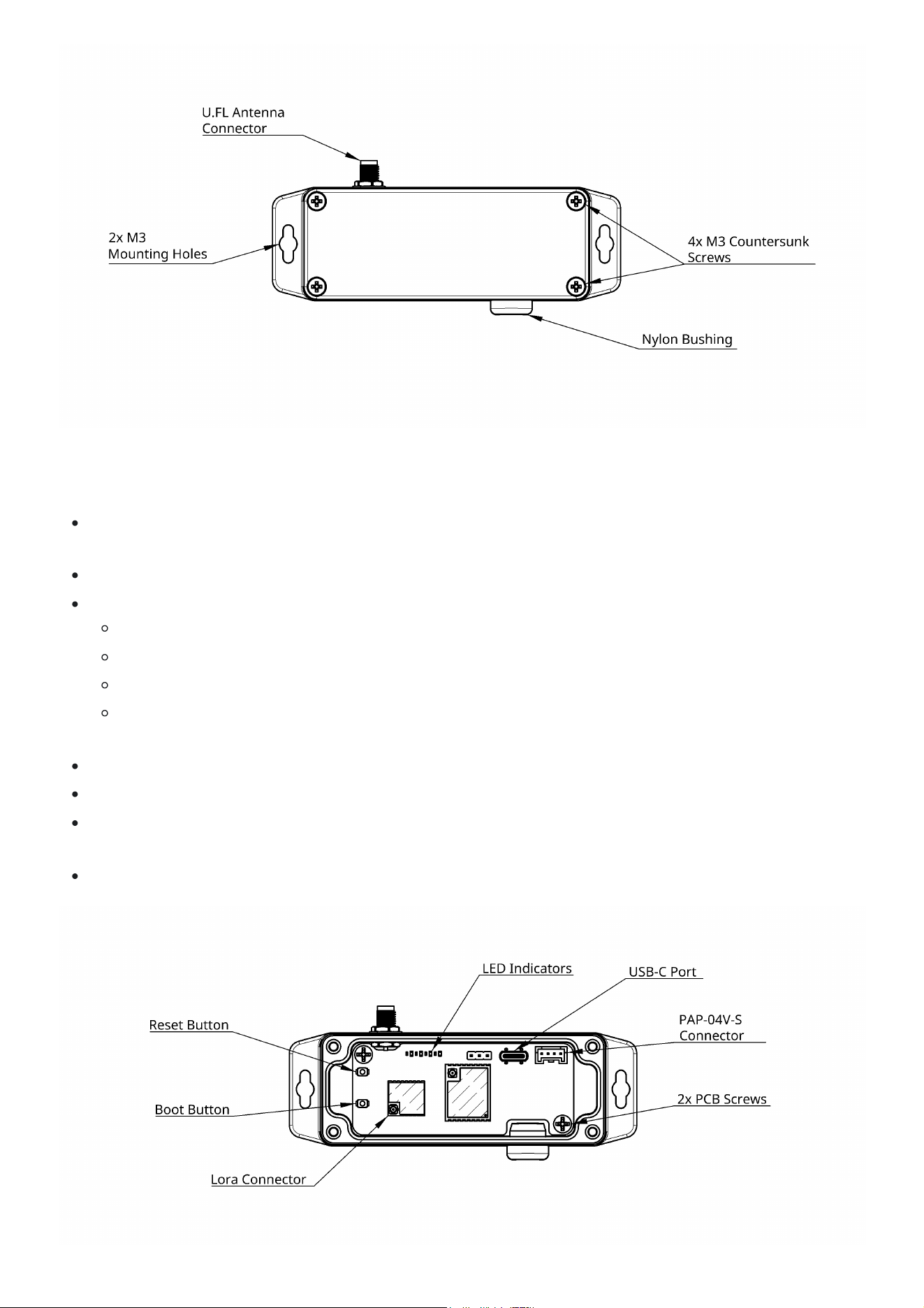
2.3.1 External
U.FL Antenna Connector: Connects the antenna for wireless communication.
Mounting Holes: Allows for secure mounting via appropriate fixings.
Countersunk Screws: Allows for easy opening of the device.
Nylon Bushing: Facilitates the entry of cables into the device.
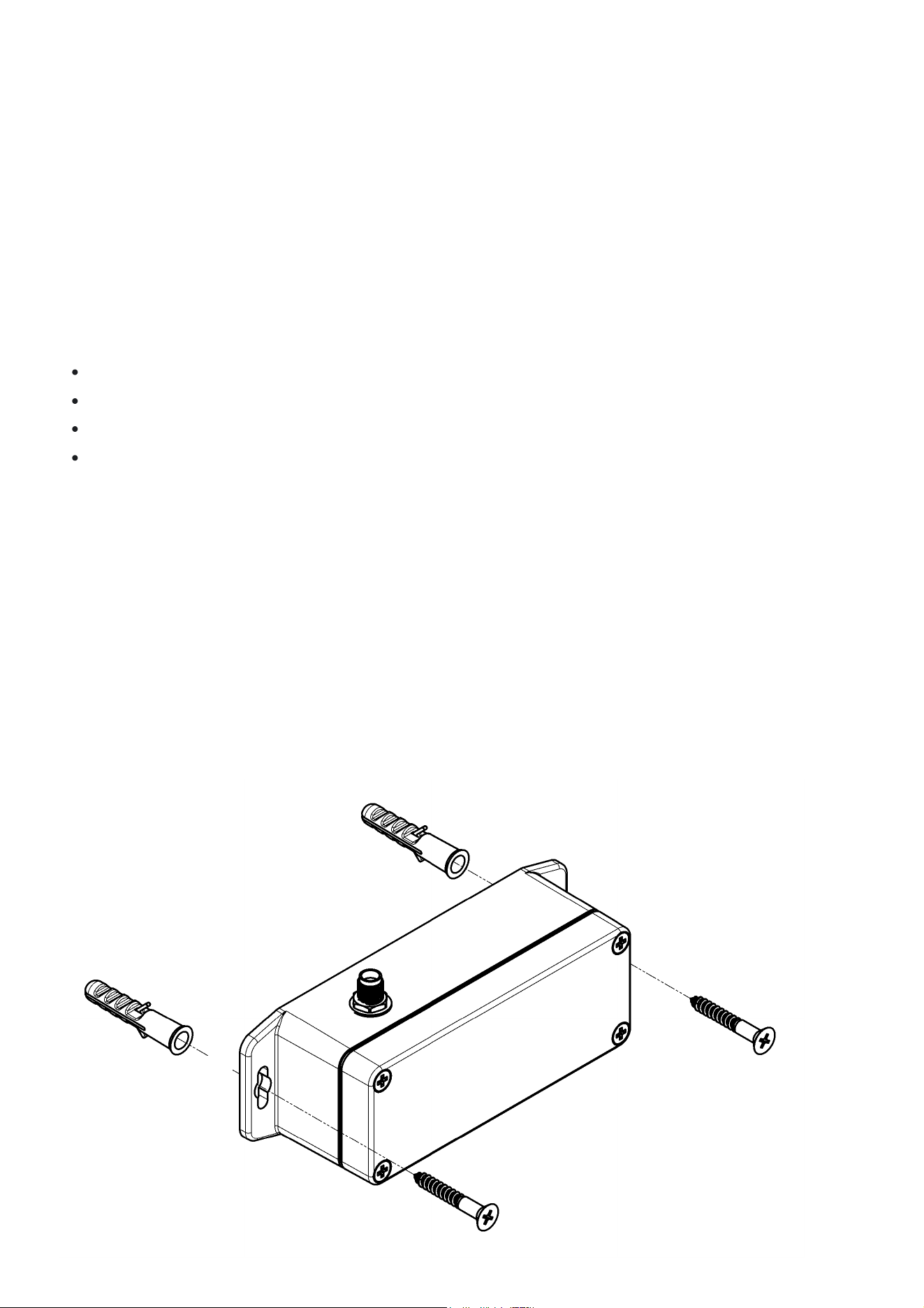
2.3.2 Internal
Reset Button: Pressing this button will reset the UART Long Range Adaptor (LRA), restart the firmware and publish a
lora message.
Boot Button: Used to enter the device into Boot mode for firmware updates
LED Indicators: Used to indicate device operation status's.
Red PWR light - When active indicates the device is powered.
Green TX light - When periodically flashing indicates communication.
Blue RX light - When periodically flashing indicates communicationn.
Orange L1 light - Will be inactive in normal operation. If reset is pressed L1 will illuminate momentarily during the
reboot cycle.
Lora Connector: Connects the U.FL Antenna Connector to the internal PCB.
USB-C Port: Provides a connection point to update the device firmware.
CN Connector: Connection point for the PAP-04V-S Connector linking the Long Range Adaptor (LRA) to the Air
Conditioner UART port (CN6, CN65 or CN75).
PCB Screws: Used to secure the PCB in the enclosure.
3. Installation & Configuration
3.1. Mounting
The UART Long Range Adaptor (LRA) can be mounted in several ways depending on the type of air conditioning system. In
all cases, the antenna must remain vertical (unless specifically noted). The UART Long Range Adaptor (LRA) should always
be mounted in a location such that it will not experience extreme high or low temperatures, liquids or high humidity. Use
either the provided Velcro tape or fixings, depending on the surface and accessibility.
General Notes
Keep the antenna vertical and unobstructed for best signal performance.
Use existing penetrations where possible to avoid damaging the air conditioning unit.
Velcro tape is preferred where drilling may risk damage to internal components.
Ensure the cable path is tidy, protected, and free from heat sources or moving parts.
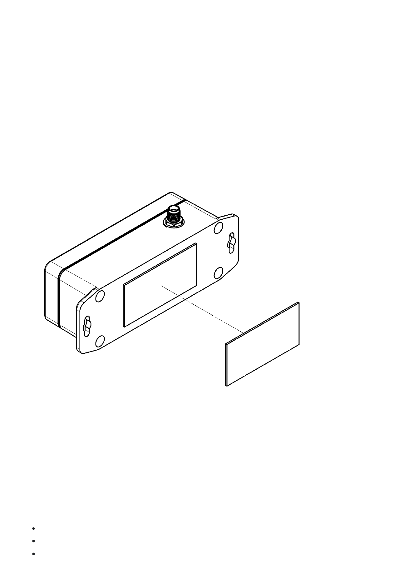
3.1.1 Direct Mounting
The UART Long Range Adaptor (LRA) can be mounted via fixings utilising the mounting clips depending on the type of air
conditioning system and mounting location.
Direct Mounting Process:
1. Position the UART Long Range Adaptor (LRA) against the mounting location & mark the fixing points.
2. Drill the holes & insert wall plugs if required.
3. Secure the UART Long Range Adaptor (LRA) using appropriate screws or fixings.
4. Gently pull forward to confirm it is firmly mounted.
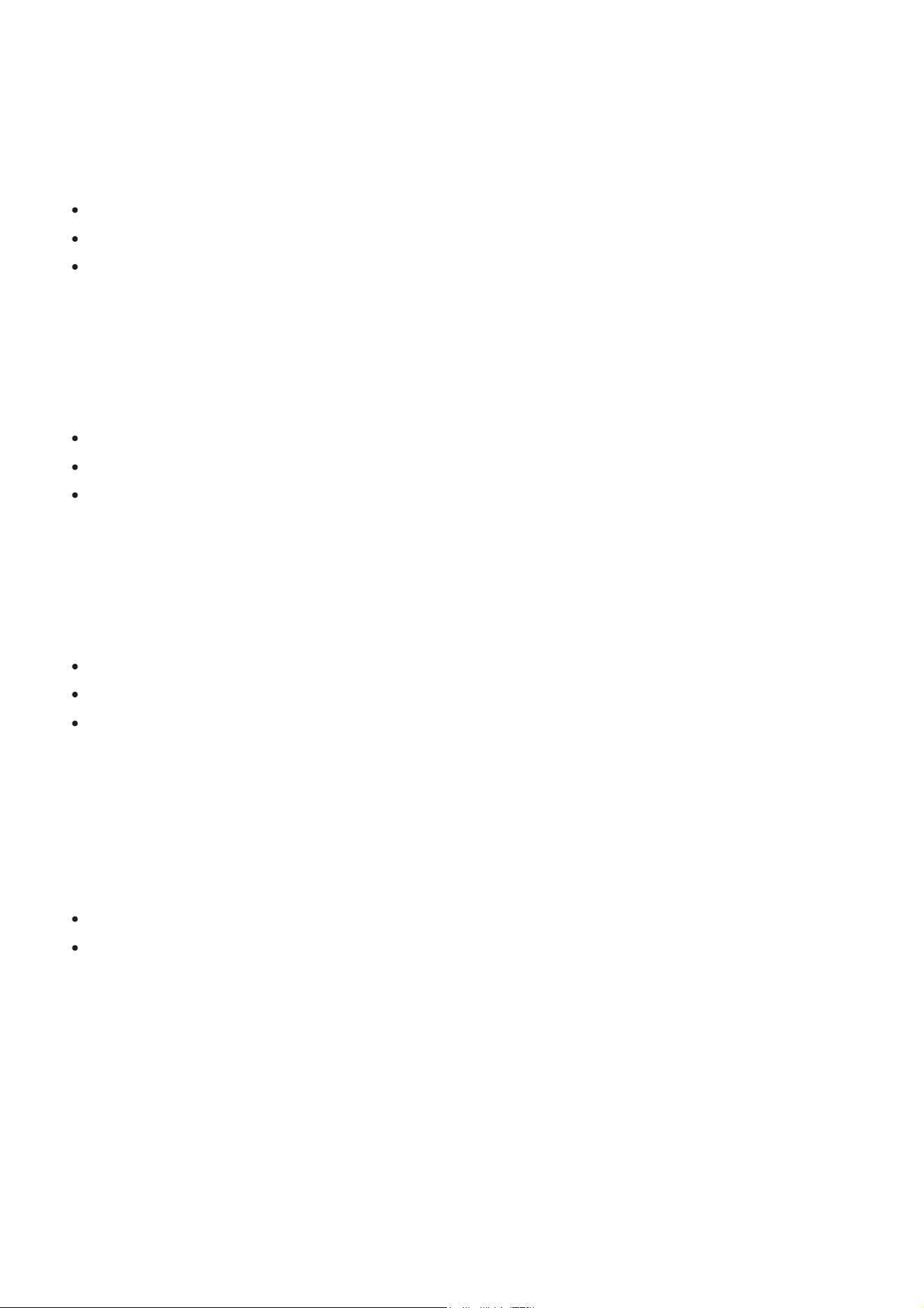
3.1.2 Adhesive Mounting
The UART Long Range Adaptor (LRA) can be mounted via adhesive velcro tape depending on the type of air conditioning
system and mounting location.
Adhesive Mounting Process:
1. Clean the mounting surface with a suitable cleaner to remove dust, grease, or other contaminants.
2. Peel the backing strips off one side of the Velcro pads and stick them to the back of the UART Long Range Adaptor
(LRA) device.
3. Then, remove the remaining backing strips and press the UART Long Range Adaptor (LRA) firmly against the wall or
surface where it will be mounted. Maintain firm pressure for approximately 30 seconds to ensure a strong bond.
3.3 Unit Mounting Locations
The UART Long Range Adaptor (LRA) can be mounted in various locations depending on the type of air conditioning
system. The following sections outline the recommended mounting locations for different system types.
3.3.1 Split Systems
The UART Long Range Adaptor (LRA) can be mounted:
On the unit — either at the bottom, top, or side of the outdoor case.
On the wall next to the unit — horizontally or vertically.
Inside trunking — above or beside cable penetrations.
Choose the closest practical location to the electrical PCB. Ensure the antenna is vertical and that cables are routed cleanly
via existing penetrations or wall cavities.
3.3.2 Ducted Systems
The UART Long Range Adaptor (LRA) can be mounted:
Top of the indoor unit
A nearby joist
Side of the indoor unit
Velcro or screws can be used, depending on the surface. Maintain a clear vertical antenna position.
3.3.3 Under-Ceiling Systems
The UART Long Range Adaptor (LRA) can be mounted::
Bottom right-hand side of the unit
Top right-hand side of the unit
Wall beside the unit
Use existing cable entry points. Attach with Velcro or screws as appropriate.
3.3.4 Cassette Systems
The UART Long Range Adaptor (LRA) can be mounted:
On the ceiling surface
On the side of the cassette unit
In the roof cavity above the cassette
Choose the closest practical location to the electrical PCB. Ensure the antenna is vertical and that cables are routed cleanly
via existing penetrations or roof cavities.
3.3.5 Floor Systems
The UART Long Range Adaptor (LRA) can be mounted:
On the side of the floor unit
On the wall next to the unit
Choose the closest practical location to the electrical PCB. Ensure the antenna is vertical and that cables are routed cleanly
via existing penetrations or roof cavities.
3.4. UART Connection
The UART Long Range Adaptor (LRA) is designed to connect to the indoor unit of the air conditioning system. The
connection is made using the supplied PAP-04V-S cable, which has a 4-pin connector on one end for the indoor unit and a
4-pin connector on the other end for the UART Long Range Adaptor (LRA).
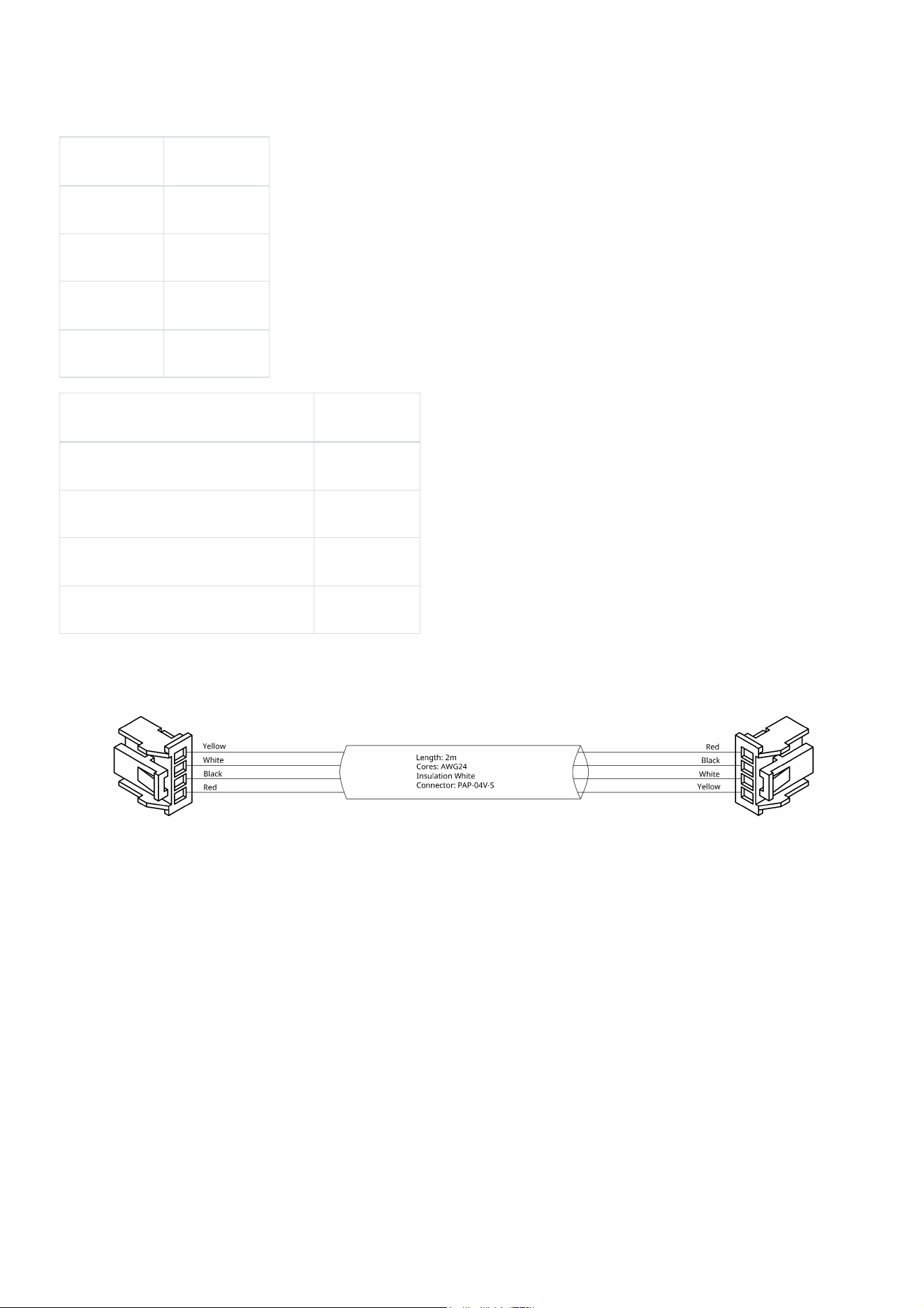
Note: If a different cable is used, ensure that the pinout matches the following configuration as pin 3 and 4 are reversed
between the indoor unit and the UART Long Range Adaptor (LRA). the provided PAP-04V-S cable is designed to match the
pinout of the indoor unit and the UART Long Range Adaptor (LRA) regardless of which end is connected to which device.
Indoor Unit
Pin 1 12VDC
Pin 2 DC Ground
Pin 3 Sending Tx
Pin 4 Receiving Rx
UART Long Range Adaptor (LRA)
Pin 1 12VDC
Pin 2 DC Ground
Pin 3 Receiving Rx
Pin 4 Sending Tx
3.5. Installation
Connect the UART Long Range Adaptor (LRA) follor the below steps:
1. Remove the cover of the UART device by loosening the 4 external screws. (Refer to section 2.3.1)
2. Attach the supplied LoRa antenna to the U.FL Antenna Connector. (Refer to section 2.3.1)
3. Locate the air conditioner unit that the UART Long Range Adaptor (LRA) device is to be installed on.
4. Remove the electrical panel cover from the air conditioner indoor unit.
For wall-mounted, floor-mounted, and under-ceiling systems: remove the plastic case of the air conditioner.
For cassette systems: remove the air intake cover.
For ducted systems: remove the electrical door/panel.
5. Locate the CN6, CN65, or CN75 plug base on the indoor unit's printed control board. The available plug depends on
the unit model. Check the air conditioner’s user guide and installation manual for details.
6. Plug the PAP-04V-S cable into the available CN6, CN65 or CN75 plug.
7. There are four LED indicators on the PCB inside the UART Long Range Adaptor (LRA) enclosure. (Refer to section
2.3.1.)
When initially powered:
PWR and TX will illuminate and hold.
After approximately 15 seconds:
L1, TX, and RX will begin alternating flashing — this indicates the UART Long Range Adaptor (LRA) is receiving
and transmitting data.
Then:
L1 will stop flashing
PWR remains solid
TX and RX continue alternating flashes periodically as the Long Range Adaptor (LRA) communicates.
8. Once connected to the correct indoor unit, ensure the UART Long Range Adaptor (LRA) is mounted securely as per
Section 2. Mounting and ensure the antenna is positioned correctly to maximise signal transmission.
9. After confirming the enclosure is correctly installed, reinstall the front cover. The device is now ready to be paired with
the onsite dashboard.
10. Reinstall the electrical panel on the indoor unit. Then reinstall the air conditioner’s plastic cover (if applicable).
3.6. Configuration
The UART Long Range Adaptor (LRA) can be configured in two ways.
Option 1 is to configure and manage the Long Range Adaptors (LRAs) via the anywAiR iO Mobile App. This method is the
simplest and most efficient as the installer can add and manage devices from anywhere in the facility using only there
mobile phone.
Option 2 is to configure and manage the Long Range Adaptors (LRAs) via anywAiR iO's engineering software, Rubix CE.
Further details outlining Lora configuration in Rubix CE can be found using the following link: LoraRaw
3.6.1 Downloading the App
When officially released add the real Apple and Google play links
Downloads
Google Play
App Store
3.6.2 Gateway Management
There are two methods to add a Rubix Compute Gateway via the mobile app.
1. Manually Entering the gateway configuration details
2. Scanning the local network for compatible Rubix Computes
Manually Adding a Gateway
1. Launch the mobile app and ensure Rubix Computes Screen is opened.
2. Press the
Add Rubix Compute
button located on the bottom right of the screen.
3. Press the
Enter Details Manually
button to select this method and navigate to the configuration.
4. Enter the appropriate information. The mandatory fields include:
Gateway Name
IP Address
Port
Username
Password
5. Press the
Connect
button located on the bottom of the screen to confirm the configuration and be automatically
navigated to the Devices screen.
Note: If you are unsure of the username and password please contact your service provider or anywAiR iO technical suport
via
support@nube-io.com
Scanning Network to Add a Gateway
1. Launch the mobile app and ensure Rubix Computes Screen is opened.
2. Press the
Add Rubix Compute
button located on the bottom right of the screen.
3. Press the
Enter Details Manually
button to select this method and initiate the network scan. A progress bar will
automatically be displayed showing the scan progress.
4. Any compatible Rubix Compute Gateways will show in the
Found Gateway's
section below the progress bar. Select
the desired Rubix Compute to enter the configuration menu and fill out the mandatory fields:
Gateway Name
Username
Password
5. Press the
Connect
button located on the bottom of the screen to confirm the configuration and be automatically
navigated to the Devices screen.
Note: If you are unsure of the username and password please contact your service provider or anywAiR iO technical suport
via
support@nube-io.com
Editing a Gateway
1. Launch the mobile app and ensure Rubix Computes Screen is opened.
2. Press on the
information
button for the gateway you wish to edit and enter the gateway information view
3. Press the
pencil
button to enter the editable settings for the rubix compute gateway.
4. Update/edit gateway information and re-enter the password.
5. Press
Update
button to save and apply the changes. The App will then navigate to the devices screen for the updated
gateway.
Deleting a Gateway
1. Launch the mobile app and ensure Rubix Computes Screen is opened.
2. Press on the
information
button for the gateway you wish to edit and enter the gateway information view
3. Press the
Delete Gateway
button at the bottom of the gateway information screen.
4. A confirmation warning will appear with the following options
Cancel
: Select this option if you wish to cancel the deletion.
Delete
: Select this option to confirm the deletion.
5. If deletion is confirmed as per Step-4 the Rubix Compute gateway will be removed and user will be navigated back to
the Rubix Computes gateways screen.
Accessing Gateway Information
1. Launch the mobile app and ensure Rubix Computes Screen is opened.
2. Press on the
information
button for the Rubix Compute Gateway you wish to enter the Device information
view.
3.6.3 Device Management
There are two methods to add a Long Range Adaptor (LRA) Device via the mobile app.
1. Manually Entering the Long Range Adaptor (LRA) device details
2. Scanning the device QR Code
Manually Adding a Long Range Adaptor (LRA)
1. Launch the mobile app and ensure Rubix Computes Screen is opened.
2. Select the Rubix Compute Gateway from the list of gateway that you intend to add a Long Range Adaptor (LRA) to by
clicking on the Gateway card. You will be navigated to the Devices screen.
3. Press the
Add Device
button located on the bottom right of the screen.
4. Press the
Enter Device Details
button to select this method and navigate to the configuration.
5. Enter the appropriate information. The mandatory fields include:
Device Name
Address UUID (8 digit ID located on the product labelling on the Long Range Adaptor (LRA) device)
History Enable/Diable (Enabled as default)
6. Press the
Continue
button located on the bottom of the screen to confirm the configuration and the device will be
created and points provisioned.
7. Once the Long Range Adaptor (LRA) device returns a response during the provisioning the controls dashboard will be
automatically generated and opened for the newly added device.
Scanning the QR Code
1. Launch the mobile app and ensure Rubix Computes Screen is opened.
2. Select the Rubix Compute Gateway from the list of gateway that you intend to add a Long Range Adaptor (LRA) to by
clicking on the Gateway card. You will be navigated to the Devices screen.
3. Press the
Add Device
button located on the bottom right of the screen.
4. Press the
Scan Device QR
button to select this method and navigate to the configuration.
5. Scan the QR Code displayed on the Long Range Adaptor (LRA) device.
6.
TBC
Editing a Device
1. Launch the mobile app and navigate from the Rubix Computes screen to the Devices Screen for the appropriate
gateway.
2. Press on the
information
button for the Long Range Adaptor (LRA) you wish to edit and enter the Device
information view
3. Press the
pencil
button to enter the editable settings for the Long Range Adaptor (LRA) device.
4. Update/edit device information.
5. Press
Update
button to save and apply the changes. The App will then navigate to the control dashboard for the
updated device.
Deleting a Device
1. Launch the mobile app and navigate from the Rubix Computes screen to the Devices Screen for the appropriate
gateway.
2. Press on the
information
button for the Long Range Adaptor (LRA) you wish to edit and enter the Device
information view
3. Press the
Delete Device
button at the bottom of the device information screen.
4. A confirmation warning will appear with the following options
Cancel
: Select this option if you wish to cancel the deletion.
Delete
: Select this option to confirm the deletion.
5. If deletion is confirmed as per Step-4 the Long Range Adaptor (LRA) device will be removed and user will be
navigated back to the Devices screen.
Accessing Device Information
1. Launch the mobile app and navigate from the Rubix Computes screen to the Devices Screen for the appropriate
gateway.
2. Press on the
information
button for the Long Range Adaptor (LRA) you wish to enter the Device information
view.
4. Operation Guide
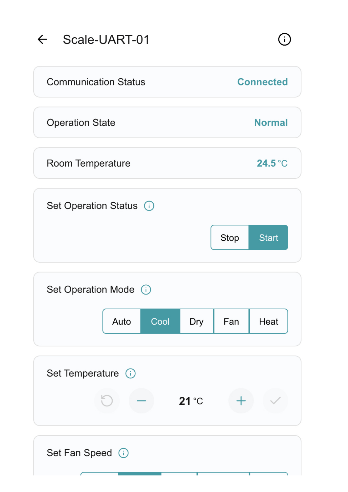
The Long Range Adaptor (LRA) allows users to control and monitor compatible RAC/PAC and VRF Air Conditioning units in
a small package, reducing the installation time and bypassing the AT command interface.
The Long Range Adaptor (LRA) interface dynamically configures the control panel based on the connected unit model,
reflecting only the operating modes and control points supported by that model.
The following are key control and monitoring points available to the user:
Operation Control: Enable the unit on and off.
Mode Control: Switch between cool, heat, dry, auto, and fan modes.
Temperature Setpoint Control: Adjust heating/cooling temperature setpoint.
Cooling setpoint 18 to 30 degrees Celsius
Heating setpoint 16-18 to 30 degrees Celsius (low limit model dependent)
Fan Speed Control: Control fan speed (model dependent).
Louvre Direction Control: Adjust vertical and horizontal louvre position and louvre swing operation (model dependent).
Return Air Temperature Monitoring: Monitor the return air temperature.
Error Status Reporting: Retrieve the error status and error code.
4.1. Device Details
For additional device details press on the
information
button .
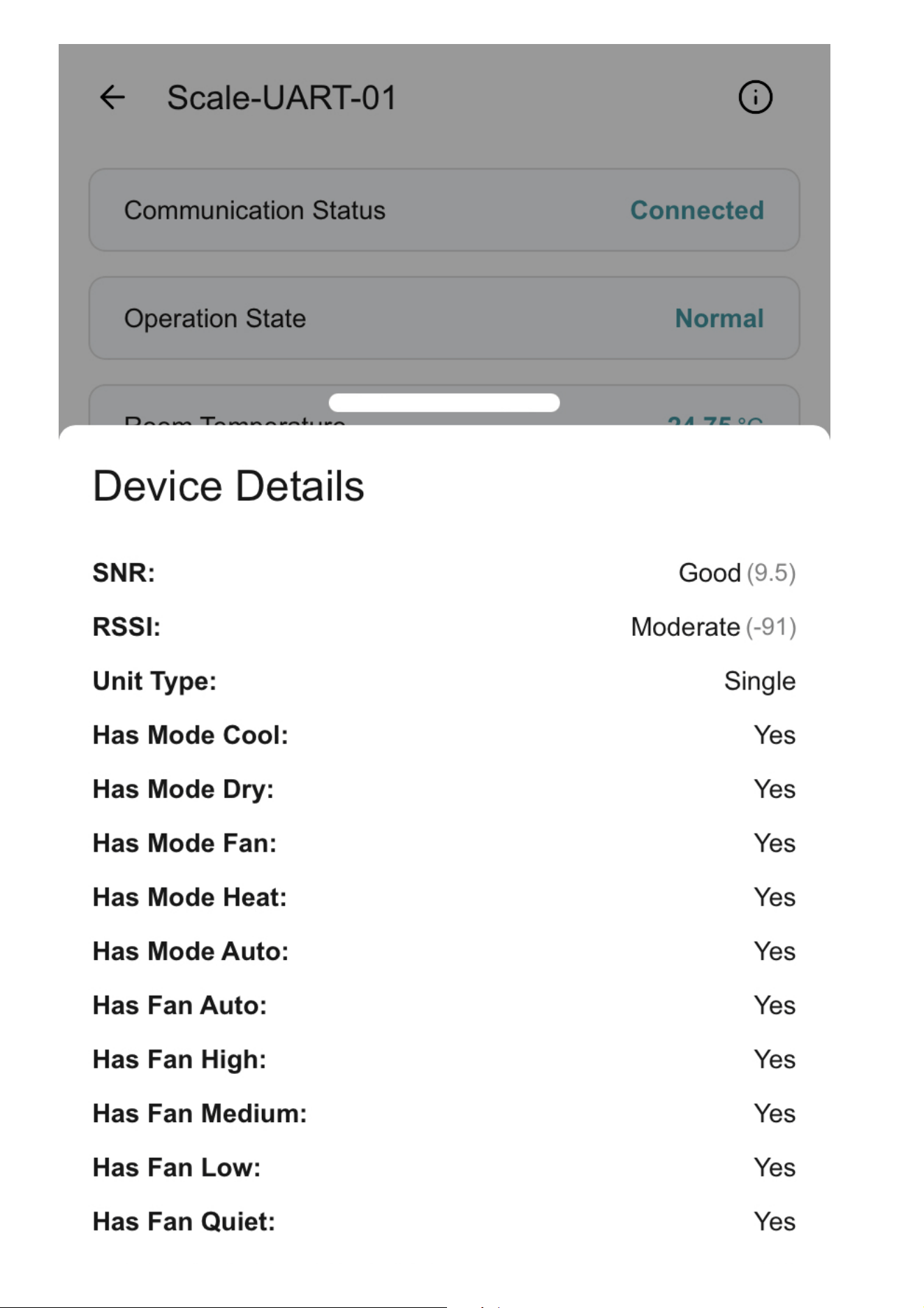
The Device Details screen displays additional information for device monitoring, including wireless signal quality, unit type,
and available control and louver parameters.
Recieved signal strength indicator (RSSI): Indicates the strength of the wireless signal between the device and the
gateway. Stronger signals improve communication reliability.
GOOD = 0 to -90
MODERATE = -90 TO -110
POOR = Less than -110
Sound to Noise Ratio: Indicates the quality of the wireless signal relative to background noise. Higher values represent
clearer and more reliable communication.
GOOD = Greater than 0
MODERATE = 0 to -10
POOR = Less than -10
Unit Type: Identifies the type of air conditioning system connected.
Examples: Single, Ducted
Available control variables: Displays which control functions are supported by the connected unit model.
Example: Has Mode Cool = Yes
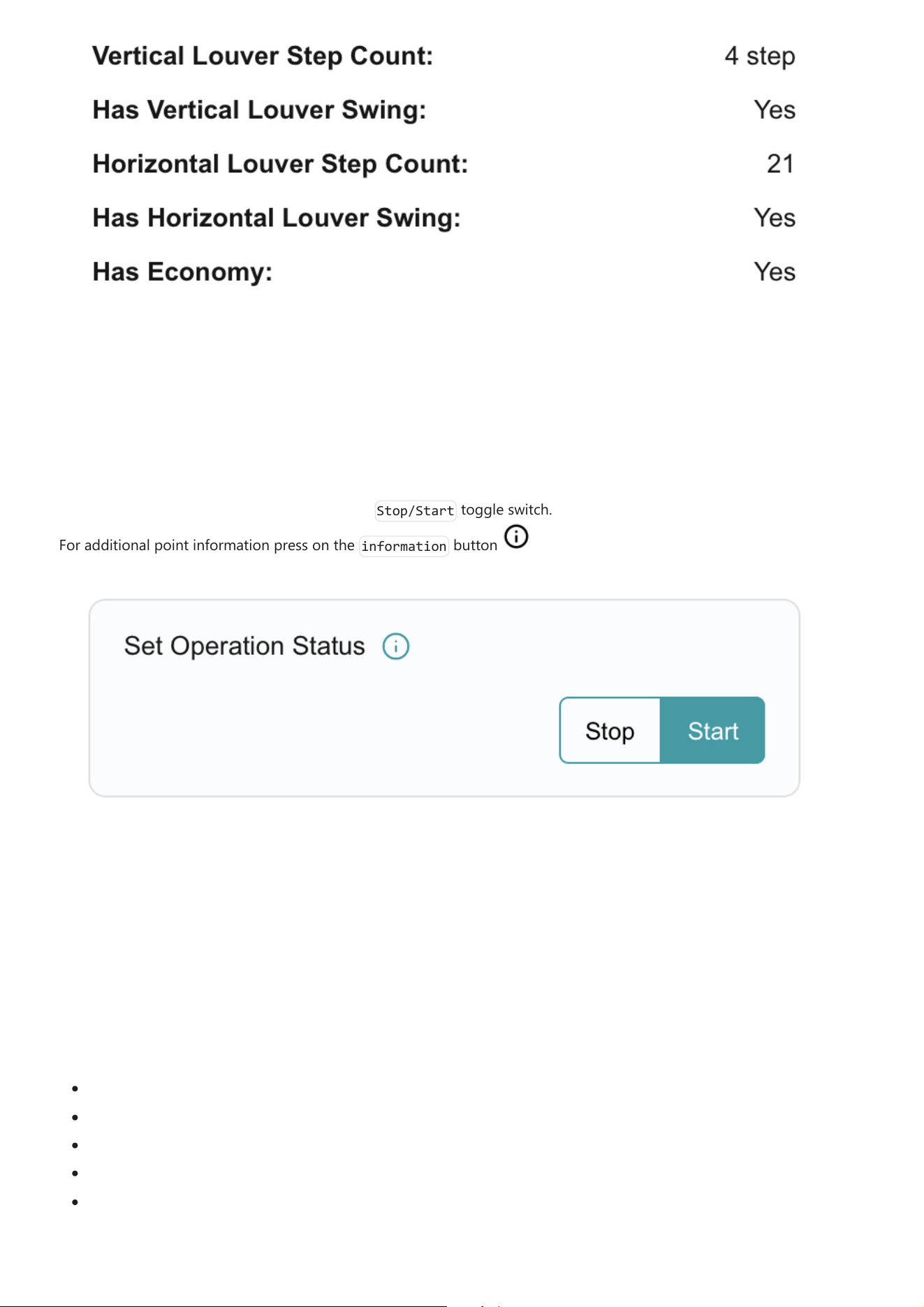
Louver variables: Displays the supported louver control options for the unit.
Example: Has Vertical Louver Swing = Yes
Vertical Louver Step Count = 4 Steps
4.2. Operation Control
Users can control the unit’s operation using the
Stop/Start
toggle switch.
For additional point information press on the
information
button .
4.3. Mode Control
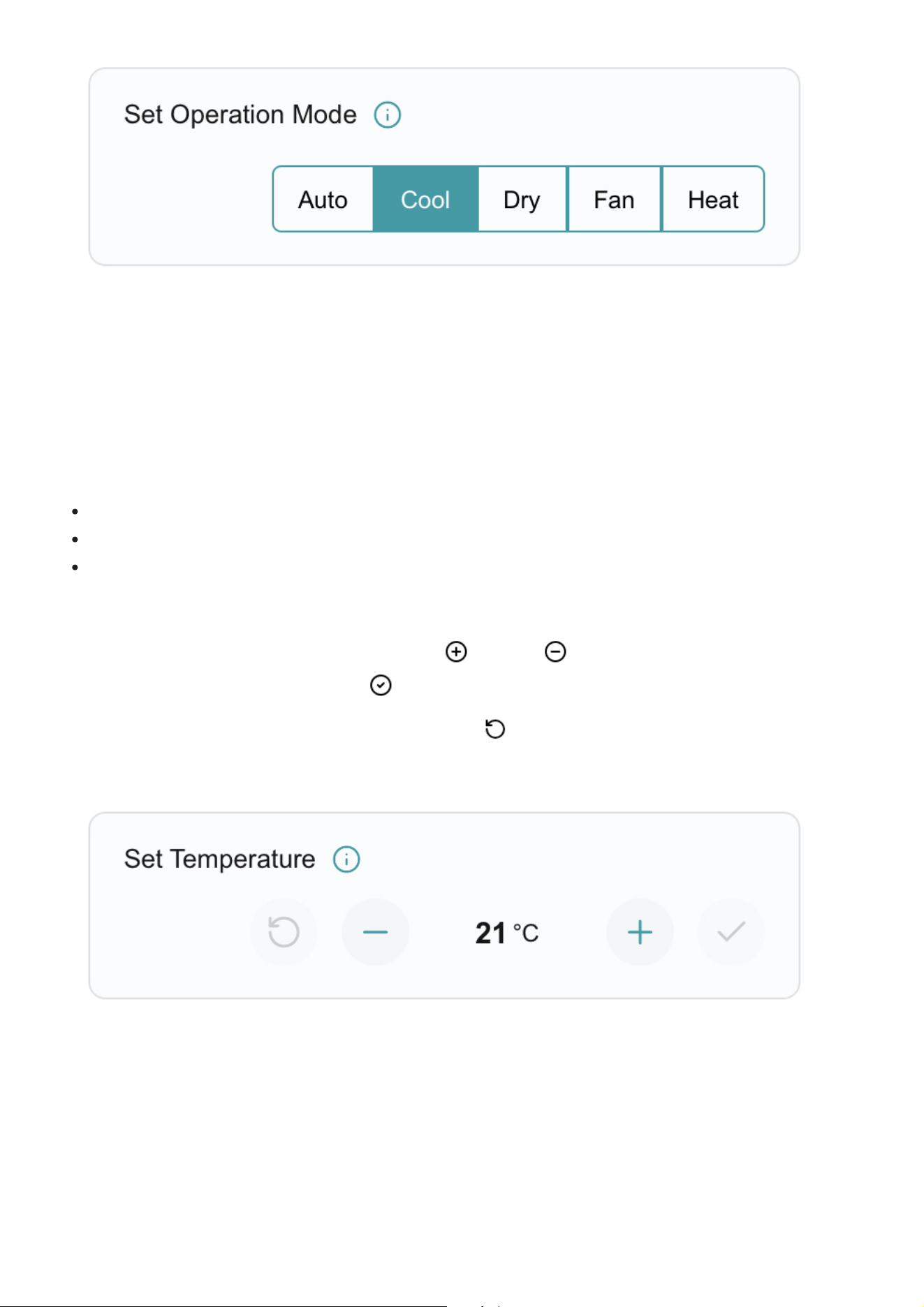
Users can control the unit’s operating mode by pressing on the desired mode within the selector switch. Available modes
are model-dependent and may vary by unit. To check available modes on the selected unit please follow the steps outlined
in section 4.1. Device Details.
Available operating modes include:
Auto: The unit automatically selects heating or cooling based on the current room temperature and the setpoint.
Cool: Actively cools the space to reach and maintain the selected temperature.
Dry: Reduces humidity in the space with minimal cooling, helping improve comfort in humid conditions.
Fan: Circulates air within the space without heating or cooling.
Heat: Actively heats the space to reach and maintain the selected temperature.
For further details on each operating mode, refer to the unit’s user manual.
4.4. Temperature Setpoint Control
Users can adjust the temperature setpoint to control the temperature maintained by the unit. The setpoint can be
increased or decreased in 0.5°C increments within the following ranges.
Cooling/Auto/Dry: Setpoint range is 18 to 30 degrees Celsius
Heating: Setpoint 16-18 to 30 degrees Celsius (Low limit model dependent. Refer to the unit’s user manual)
Fan: Setpoint control is diasbled in fan mode as the unit is circulating air within the space without heating or cooling.
Temperature Setpoint can be changed using the following steps.
1. Increase or decrease the setpoint value using the plus and minus buttons to the desired setpoint.
2. Once at the desired setpoint press the tick button to save and apply the new setpoint.
Canecling Changes: To cancel a setpoint change press the reset button prior to Step-2. This will revert the setpoint to
the previous value.
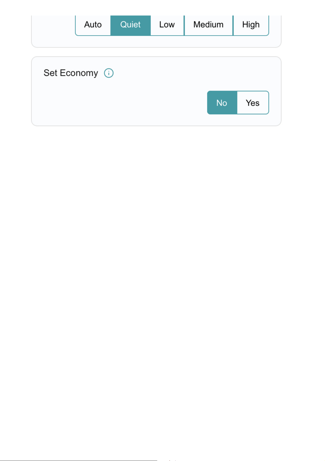
4.5. Fan Speed Control
Users can control the unit’s fan speed by pressing on the desired speed within the selector switch. Available fan speeds are
model-dependent and may vary by unit. To check available fan speeds on the selected unit please follow the steps
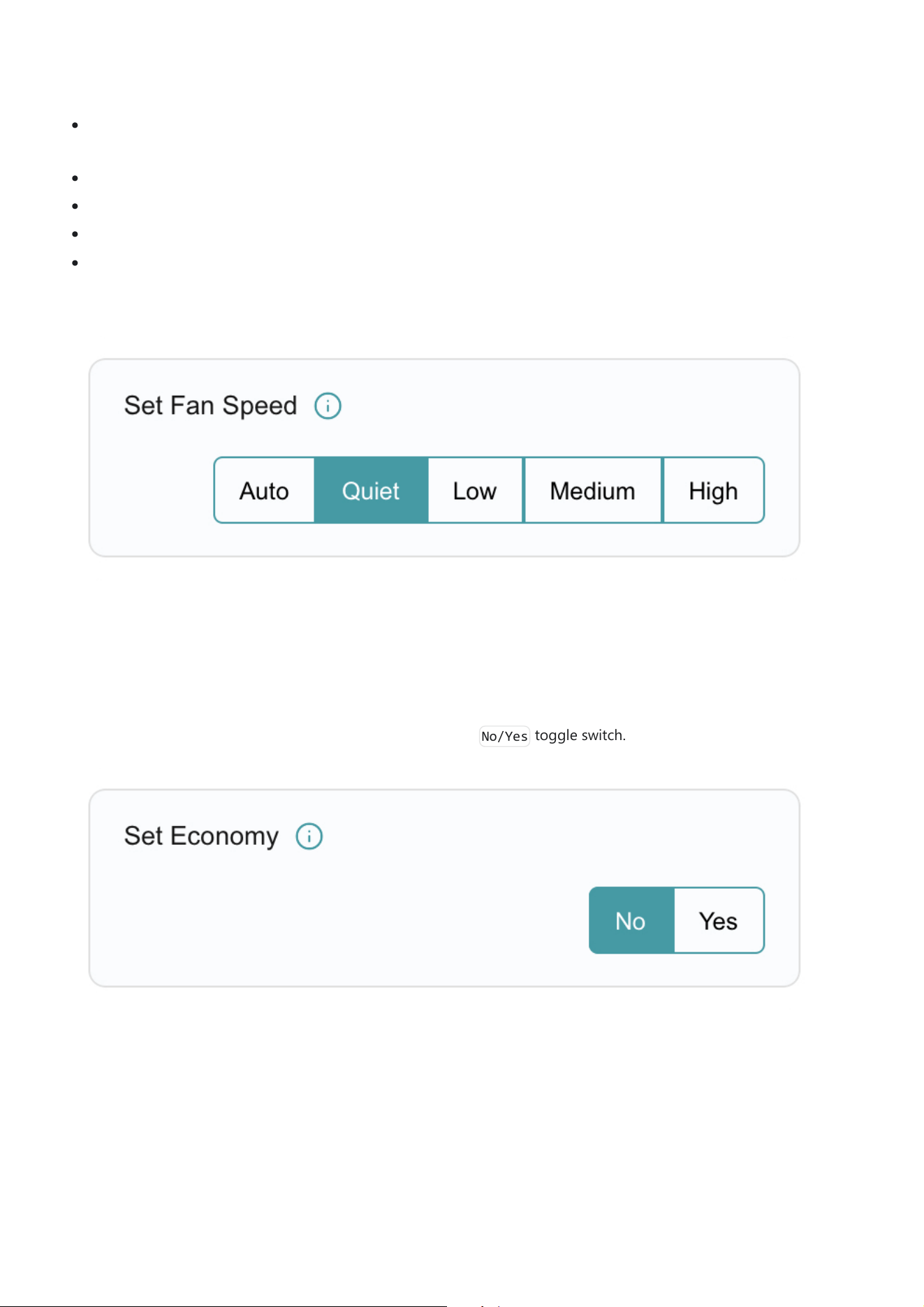
outlined in section 4.1. Device Details.
Available fan speeds include:
Auto: The unit automatically adjusts the fan speed based on the current room temperature and the set temperature
for optimal comfort and efficiency.
Quiet: Operates the fan at a very low speed to minimize noise, ideal for sleeping or quiet environments.
Low: Runs the fan at a low speed for gentle air circulation while maintaining comfort.
Medium: Provides a balanced fan speed for effective cooling or heating while maintaining moderate noise levels.
High: Runs the fan at maximum speed to quickly reach the desired temperature or improve air circulation.
For further details on each fan speed mode, refer to the unit’s user manual.
4.6. Economy Mode Control
Users can enable or disable the unit’s economy mode using the
No/Yes
toggle switch.
4.7. Vertical Louver Control
Users can adjust the vertical louvers to a position of their choosing or enable the louver swing function built into the unit.
The louver steps can be increased or decreased in 1 step increments with the amount of steps available varying based on
the unit the Long Range Adaptor (LRA) is connected to. To check the step count available refer to section 4.1. Device
Details.
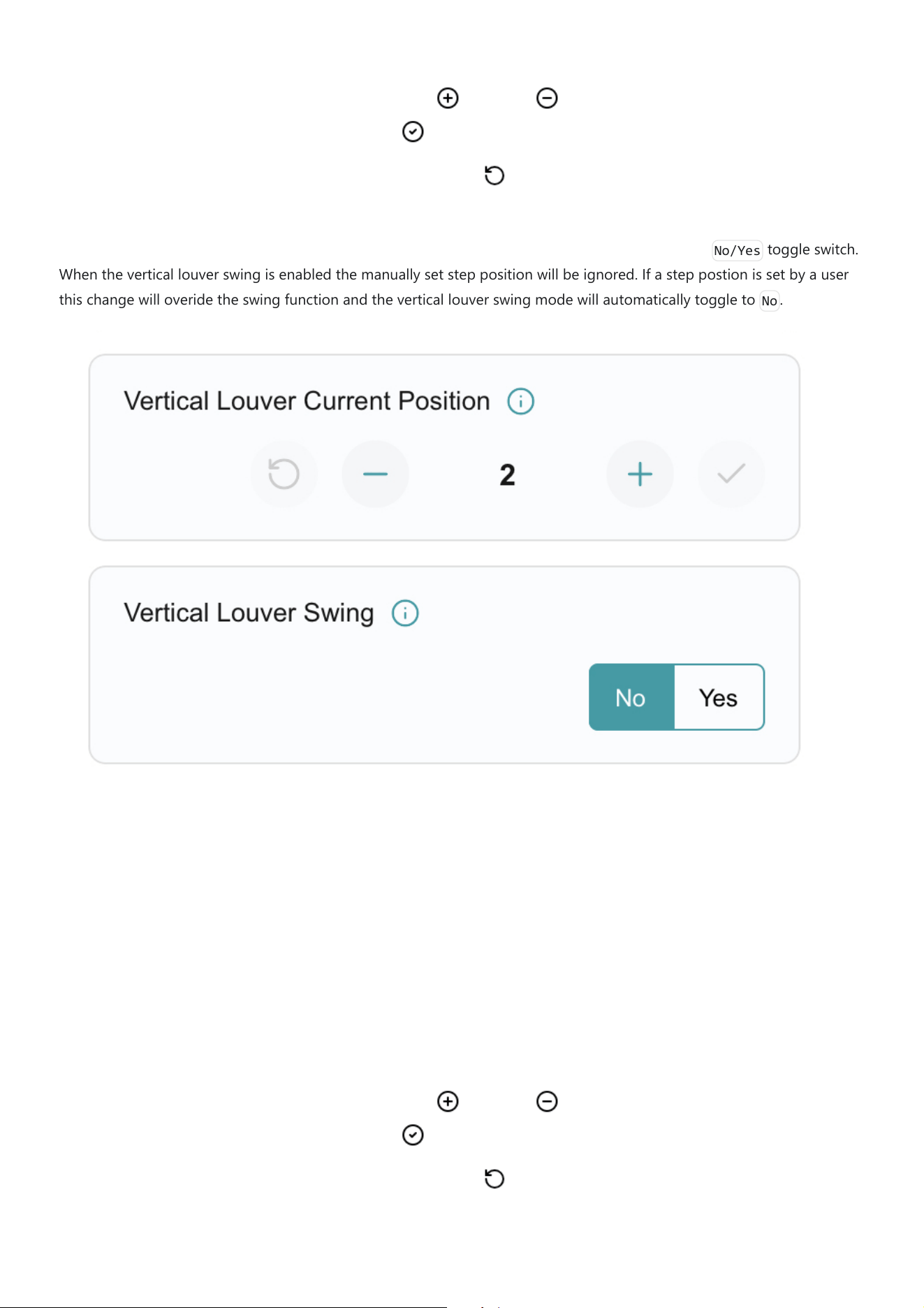
Vertical louver positions can be changed using the following steps.
1. Increase or decrease the step position value the plus and minus buttons to the desired setpoint.
2. Once at the desired step position press the tick button to save and apply the new position.
Canecling Changes: To cancel a position change press the reset button prior to Step-2. This will revert the step
position to the previous value.
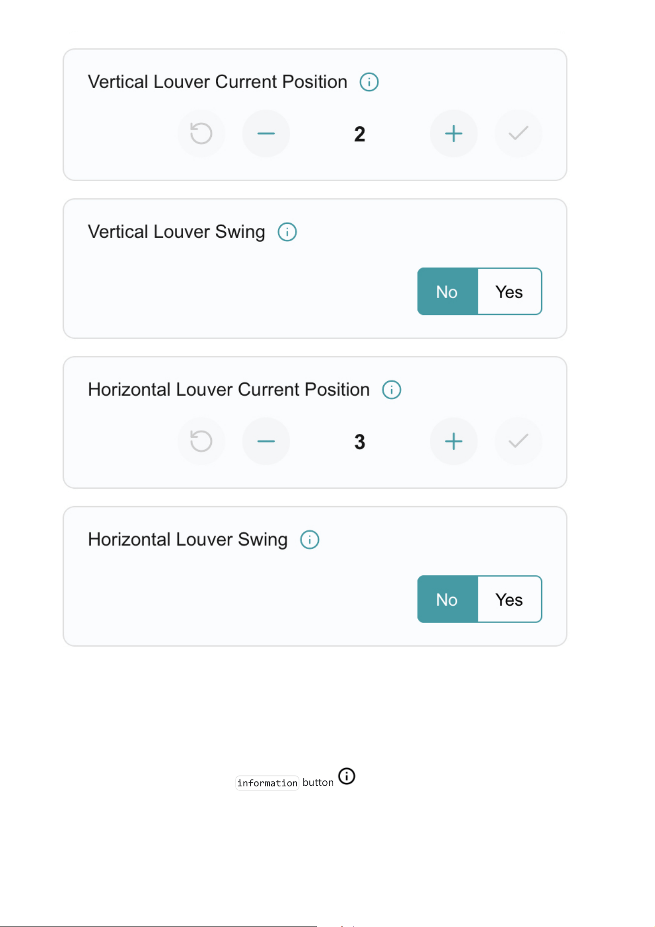
Vertical Louver Swing: Users can enable or disable the unit’s vertical louver swing mode using the
No/Yes
toggle switch.
When the vertical louver swing is enabled the manually set step position will be ignored. If a step postion is set by a user
this change will overide the swing function and the vertical louver swing mode will automatically toggle to
No
.
4.8. Horizontal Louver Control
Users can adjust the horizontal louvers to a position of their choosing or enable the louver swing function built into the
unit. The louver steps can be increased or decreased in 1 step increments with the amount of steps available varying based
on the unit the Long Range Adaptor (LRA) is connected to. To check the step count available refer to section 4.1. Device
Details.
Horizontal louver positions can be changed using the following steps.
1. Increase or decrease the step position value the plus and minus buttons to the desired setpoint.
2. Once at the desired step position press the tick button to save and apply the new position.
Canecling Changes: To cancel a position change press the reset button prior to Step-2. This will revert the step
position to the previous value.
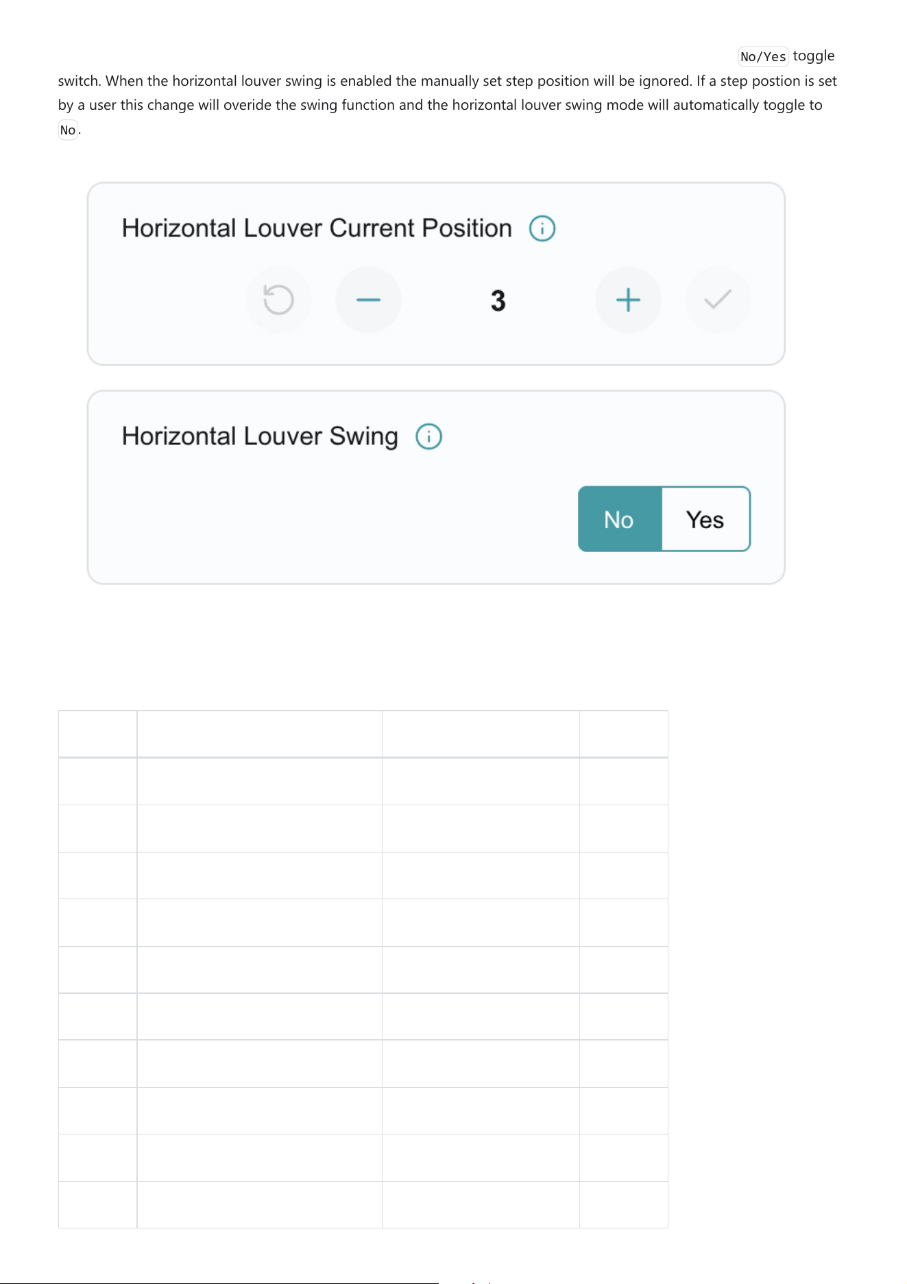
Horizontal Louver Swing: Users can enable or disable the unit’s horizontal louver swing mode using the
No/Yes
toggle
switch. When the horizontal louver swing is enabled the manually set step position will be ignored. If a step postion is set
by a user this change will overide the swing function and the horizontal louver swing mode will automatically toggle to
No
.
5. UART Long Range Adaptor (LRA) Point Register
Point ID Point Name New Variable (Data Type) Attribute
N/A snr float Read Only
N/A rssi float Read Only
1 Communication Status uint8 Read Only
2 Unit Type uint8 Read Only
3 Has Economy bool Read Only
10 Has Mode Cool bool Read Only
11 Has Mode Dry bool Read Only
12 Has Mode Fan bool Read Only
13 Has Mode Heat bool Read Only
14 Has Mode Auto bool Read Only

Point ID Point Name New Variable (Data Type) Attribute
15 Has Fan Auto bool Read Only
16 Has Fan High bool Read Only
17 Has Fan Medium bool Read Only
18 Has Fan Low bool Read Only
19 Has Fan Quiet bool Read Only
20 Vertical Louver Step Count uint8 Read Only
21 Has Vertical Louver Swing bool Read Only
22 Vertical Louver 1 Step Count uint8 Read Only
23 Has Vertical Louver 1 Swing bool Read Only
24 Vertical Louver 2 Step Count uint8 Read Only
25 Has Vertical Louver 2 Swing bool Read Only
26 Vertical Louver 3 Step Count uint8 Read Only
27 Has Vertical Louver 3 Swing bool Read Only
28 Vertical Louver 4 Step Count uint8 Read Only
29 Has Vertical Louver 4 Swing bool Read Only
30 Horizontal Louver Step Count uint8 Read Only
31 Has Horizontal Louver Swing bool Read Only
32 Horizontal Louver 1 Step Count uint8 Read Only
33 Has Horizontal Louver 1 Swing bool Read Only
34 Horizontal Louver 2 Step Count uint8 Read Only
35 Has Horizontal Louver 2 Swing bool Read Only
36 Horizontal Louver 3 Step Count uint8 Read Only
37 Has Horizontal Louver 3 Swing bool Read Only
38 Horizontal Louver 4 Step Count uint8 Read Only

Point ID Point Name New Variable (Data Type) Attribute
39 Has Horizontal Louver 4 Swing bool Read Only
40 Set Operation Status bool Write
41 Set Operation Mode uint8 Write
42 Set Temperature temp Write
43 Set Fan uint8 Write
44 Vertical Louver Current Position uint8 Write
45 Vertical Louver Swing bool Write
46 Vertical Louver 1 Current Position uint8 Write
47 Verticle Louver 1 Swing bool Write
48 Vertical Louver 2 Current Position uint8 Write
49 Verticle Louver 2 Swing bool Write
50 Vertical Louver 3 Current Position uint8 Write
51 Verticle Louver 3 Swing bool Write
52 Vertical Louver 4 Current Position uint8 Write
53 Verticle Louver 4 Swing bool Write
54 Horizontal Louver Current Position uint8 Write
55 Horizontal Louver Swing bool Write
56 Room Temperature temp Read Only
57 Error State uint16 Read Only
58 Error Code uint16 Read Only
59 Set Economy bool Write

FCC Caution.
This device complies with part 15 of the FCC Rules. Operation is subject to the following two
conditions:
(1) This device may not cause harmful interference, and
(2) this device must accept any interference received, including interference that may cause
undesired operation.
Any Changes or modifications not expressly approved by the party responsible for compliance
could void the user's authority to operate the equipment.
Note: This equipment has been tested and found to comply with the limits for a Class B digital
device, pursuant to part 15 of the FCC Rules. These limits are designed to provide reasonable
protection against harmful interference in a residential installation. This equipment generates
uses and can radiate radio frequency energy and, if not installed and used in accordance with the
instructions, may cause harmful interference to radio communications. However, there is no
guarantee that interference will not occur in a particular installation. If this equipment does
cause harmful interference to radio or television reception, which can be determined by turning
the equipment off and on, the user is encouraged to try to correct the interference by one or
more of the following measures:
-Reorient or relocate the receiving antenna.
-Increase the separation between the equipment and receiver.
-Connect the equipment into an outlet on a circuit different from that to which the receiver is
connected.
-Consult the dealer or an experienced radio/TV technician for help.
FCC Radiation Exposure Statement:
This equipment complies with FCC radiation exposure limits set forth for an uncontrolled
environment. This equipment should be installed and operated with minimum distance 20 cm
between the radiator & your body.