
Datasheet
Veda™ IF913
Version 0.7
https://www.ezurio.com/
2
© Copyright 2025 Ezurio
All Rights Reserved
Veda IF913
Datasheet
Revision History
Version
Date
Notes
Contributors
Approver
0.1
13 May 2025
Preliminary release
Andrew Chen
Andy Ross
0.2
22 May 2025
Section 4:
Update Storage humidity range to 5%~95%.
Operating humidity range <85%.
Section 6:
Update the SDIO/gSPI pin details.
Section 7.2:
Correct the schematic drawing on SMIF connection (Chip select pin)
with external NOR and PSRAM.
Andrew Chen
Andy Ross
0.3
20 June 2025
Correct the pin define on pin 82-83
Andrew Chen
Andy Ross
0.4
14 July 2025
Update RF performance
Andrew Chen
Andy Ross
0.5
16 Sept 2025
Updated to reflect that Bluetooth does not support BR/EDR.
Andrew Chen
Andy Ross
0.6
2025/10/09
Add Pin-108: DMIC_CLK
Andrew Chen
Andy Ross
0.7
2025/12/10
On section 6: Add the module pin out mapping to IFX main chip pin
out
Andrew Chen
Andy Ross

https://www.ezurio.com/
3
© Copyright 2025 Ezurio
All Rights Reserved
Veda IF913
Datasheet
Contents
1 Scope .................................................................................................................................................................................................................................................. 4
2 Introduction ....................................................................................................................................................................................................................................... 4
General Description ................................................................................................................................................................................................................................. 4
3 Veda IF913 Series Feature Summary .................................................................................................................................................................................................. 6
4 Specifications ..................................................................................................................................................................................................................................... 7
5 Block Diagrams ................................................................................................................................................................................................................................. 12
Veda IF913 module Block Diagram ........................................................................................................................................................................................................ 12
6 Pin Definitions .................................................................................................................................................................................................................................. 13
7 Veda IF913 Implementation Details ................................................................................................................................................................................................. 17
Power up sequency timing .................................................................................................................................................................................................................... 17
L-C filter for Buck switching regulator ................................................................................................................................................................................................... 17
Serial Memory Interface (SMIF) Connection. ......................................................................................................................................................................................... 18
SDIO and gSPI strapping configuration .................................................................................................................................................................................................. 20
7.1.1 SDIO mode ..................................................................................................................................................................................................................... 20
7.1.2 gSPI mode ...................................................................................................................................................................................................................... 20
MHF4 and Embedded PCB antenna ....................................................................................................................................................................................................... 21
8 PCB footprint .................................................................................................................................................................................................................................... 22
9 Mechanical Specifications ................................................................................................................................................................................................................ 23
10 Material handling information ......................................................................................................................................................................................................... 25
Required Storage Conditions ................................................................................................................................................................................................................. 25
10.1.1 Prior to Opening the Dry Packing .................................................................................................................................................................................. 25
10.1.2 After Opening the Dry Packing ...................................................................................................................................................................................... 25
10.1.3 Temporary Storage Requirements after Opening .......................................................................................................................................................... 25
Baking Conditions .................................................................................................................................................................................................................................. 25
11 Surface Mount Conditions................................................................................................................................................................................................................ 27
Recommended Stencil Aperture ............................................................................................................................................................................................................ 27
Soldering profile .................................................................................................................................................................................................................................... 27
12 Cautions When Removing the SIP from the Platform for RMA ........................................................................................................................................................ 28
12.1.1 Precautions for Use ....................................................................................................................................................................................................... 28
13 Certified Antennas ........................................................................................................................................................................................................................... 29
14 Regulatory ........................................................................................................................................................................................................................................ 30
14.1 Federal Communication Commission Interference Statement ............................................................................................................................................. 30
14.2 Industry Canada statement .................................................................................................................................................................................................. 31
14.3 EU & UKCA Declaration of Conformity .................................................................................................................................................................................. 33
15 Additional Information ..................................................................................................................................................................................................................... 36

https://www.ezurio.com/
4
© Copyright 2025 Ezurio
All Rights Reserved
Veda IF913
Datasheet
1 Scope
This document describes key hardware aspects of the Ezurio Veda™ IF913 series wireless modules which is a ultra-lower power, single chip connected MCUs with 1x1
Wi-Fi 6E, Bluetooth® Low Energy 5.4, Matter and IP networking. Integrated MCU, Radio, PMU, Flash and PSRAM in 11x7mm size that targeted at Internet-of- Things
(IoT) applications for stand-alone operation or to offload a host-processor.
This document is intended to assist device manufacturers and related parties with the integration of this radio into their host devices. Data in this document is drawn
from several sources and includes information found in the Infineon CYW55913 Reversion C 2024-10-30 data sheet, along with other documents provided by
Infineon.
Note: The information in this document is subject to change. Please contact Ezurio to obtain the most recent version of this document.
2 Introduction
General Description
The Veda IF913 series wireless module is a highly integrated, small form factor Wi-Fi/Bluetooth module that is optimized for low-power mobile devices, featuring:
• MCU: 192 MHz Arm® Cortex®-CM33, runs the Wi-Fi and Networking Stacks.
• Memory:
– On-Chip memory: 2048-KB ROM and 768-KB RAM. (No Embedded Memory variant)
– Embedded external memory: 8M PSRAM, 8M Flash. (Embedded Memory, 8M PSRAM, 8M Flash variant)
Note: For other embedded memory size, please contact Ezurio.
• Wi-Fi:
– 1X1, IEEE 802.11a/b/g/n/ac/ax compliant.
– Tri-band (2.4/5-7 GHz), 20 MHz channels supporting PHY data rates up to 802.11ax (MCS11 1024-QAM 5/6).
– Transmit (TX) power with internal PA and LNA.
– Wi-Fi 6 release feature:
• OFDMA uplink and downlink as STA
• Downlink multi-user MIMO as STA
• Individual target-wake-time (TWT)
• Bluetooth
®
:
– Bluetooth® 5.4 (Bluetooth® Low Energy)
• Advertising Coding Selection
• Encrypted Advertising Data
• LE Generic Attribute Profile (GATT) Security Levels Characteristic
– Bluetooth® Low Energy 5.0/5.1/5.2/5.3 features
• LE long range
• LE 2 Mbps
• LE mesh
• Advertising extensions
• Security:
– Arm® Trustzone Cryptocell 312
– Life cycle management
– Crypto key establishment and management Crypto offloads
– Secure boot
– Wi-Fi and Bluetooth® independent firmware authentication
– Firmware encryption
– Attestation
– Anti-rollback prevention
The Veda IF913 integrated with all WLAN and Bluetooth functionality in a small package supports a low cost and simple implementation. The radio is pre-calibrated
and integrates the complete transmit/receive RF paths including bandpass filter, diplexer, switches, reference crystal oscillator, and power management units (PMU).
It is available in 7x11x1.4mm solder-down LGA form factors with an RF trace pin out for both Wi-Fi and BT.
A reference certified embedded PCB antenna or the implementation of MHF4 connector for external antennas are available on Veda IF91x DVK, please contact Ezurio
for detail information. A list of certified external antennas is shown in 錯誤! 找不到參照來源。.
Ordering information is listed in Table 1. Please contact Ezurio Sales/FAE for further information.

https://www.ezurio.com/
5
© Copyright 2025 Ezurio
All Rights Reserved
Veda IF913
Datasheet
Table 1: Product ordering information
Part Number
Description
453-00400R
Module, Veda IF913, SIP, Tri Band, No Embedded Memory, RF Trace Pin, Tape and Reel
453-00400C
Module, Veda IF913, SIP, Tri Band, No Embedded Memory, RF Trace Pin, Cut Tape
453-00401R
Module, Veda IF913, SIP, Tri Band, Embedded Memory, 8M PSRAM, 8M Flash, RF Trace Pin, Tape and Reel
453-00401C
Module, Veda IF913, SIP, Tri Band, Embedded Memory, 8M PSRAM, 8M Flash, RF Trace Pin, Cut Tape
453-00400-K1
Development Kit, Module, Veda IF913, SIP, Tri Band, External Memory, RF Trace Pin
https://www.ezurio.com/
6
© Copyright 2025 Ezurio
All Rights Reserved
Veda IF913
Datasheet
3 Veda IF913 Series Feature Summary
The Ezurio Veda IF913 series device features are described in Table 2.
Table 2: Veda IF913 series wireless module feature
Feature
Description
Radio Front End
• Integrates the complete transmit/receive RF paths including bandpass filter, diplexer, switches, reference crystal oscillator, and power
manage unit (PMU)
• Supports tri-band (2.4/5-7 GHz)
• Supports 20MHz channel bandwidth
• Supports 1x1 WLAN/Bluetooth antenna configuration
The Bluetooth® word mark and logos are registered trademarks owned by Bluetooth SIG, Inc. Any use of such marks by Ezurio is under license. Other trademarks
and trade names are those of their respective owners.
Power
Management
One buck regulator, multiple LDO regulators, and a power management unit (PMU) are integrated into the Veda IF913. All regulators are
programmable via the PMU. These blocks simplify power supply design for Bluetooth and WLAN functions in embedded designs.
Pre-Calibration
RF system tested and calibrated in production
Sleep Clock
Internal low-power oscillator accuracy is only adequate for WLAN, and not for Bluetooth®, if low power for Bluetooth®Low-Energy required.
External 32.768 KHz sleep clock is required for Bluetooth® Low Energy to support low power mode.
The 32.768 kHz precision oscillator which meets the requirements listed following table must be used.
Parameter
LPO Clock
Unit
Nominal input frequency
32.768
kHz
Frequency accuracy
±250
ppm
Duty cycle
30 – 70
%
Input signal amplitude
200 – 3300
mV, p-p
Signal type
Square-wave or sine-wave
-
Input impedance
> 100k
Ω
< 5
pF
Clock jitter (during initial startup)
< 10,000
ppm
Advanced
WLAN
• IEEE 802.11a/b/g/n/ac/ax compliant, tri-band capable (2.4/5-7 GHz)
• 1x1 MIMO providing up to 143 Mbps PHY data rate for 2.4/5-7 GHz (1024-QAM modulation)
• Supports 20 MHz bandwidth with optional SGI (1024-QAM modulation)
• On-chip power amplifiers and low-noise amplifiers for both bands
• Support wide variety of WLAN encryption: WPA2(Personal/Enterprise), WPA3 (Personal/Enterprise with 192 bit security).
Advanced
Bluetooth
• Bluetooth® 5.4 (Bluetooth® Low Energy)
– Advertising Coding Selection
– Encrypted Advertising Data
– LE Generic Attribute Profile (GATT) Security Levels Characteristic
• Bluetooth® Low Energy 5.0/5.1/5.2/5.3 features
– LE long range
– LE 2 Mbps
– LE mesh
– Advertising extensions
• Host controller interface (HCI) using a high speed UART and PCM/I2S for audio data
• Low power consumption improves battery life of IoT and embedded devices
https://www.ezurio.com/
7
© Copyright 2025 Ezurio
All Rights Reserved
Veda IF913
Datasheet
4 Specifications
Table 3: Specifications
Feature
Description
Physical size
11x7x1.4mm in 108-pin LGA package
Network communication interface
Secure Digital I/O 2.0 (1.8V only) /3.0; UART, gSPI, UART, SPI.
Main Chipset
Infineon AIROC™ CYW55913
Input Voltage Requirements
Typical DC 3.3 V, operating range from DC 3.13V to 4.8V
I/O Signalling Voltage
Typical DC 1.8 V ± 5%
Operating Temperature
-40° to +85°C (-40° to +185°F)
Operating Humidity
<85% (non-condensing)
Storage Temperature
-40° to +85°C (-40° to +185°F)
Storage Humidity
5 to 95% (non-condensing)
MSL (Moisture Sensitivity Level)
4
Maximum Electrostatic Discharge
Conductive 8KV; Air coupled 12KV (follows EN61000-4-2)
Weight – g (oz.)
TBD
Network Architecture Types
Infrastructure (client operation)
Wi-Fi Standards
IEEE 802.11ax, 11ac, 11ac, 11a/b/g/n, 11d/h, 11i, 11r, 11w, 11e, 11k, 11ai, 11v
Bluetooth Standards
Bluetooth BLE 5.0, 5.1, 5.2, 5.3, 5.4
Wi-Fi Data Rates Supported
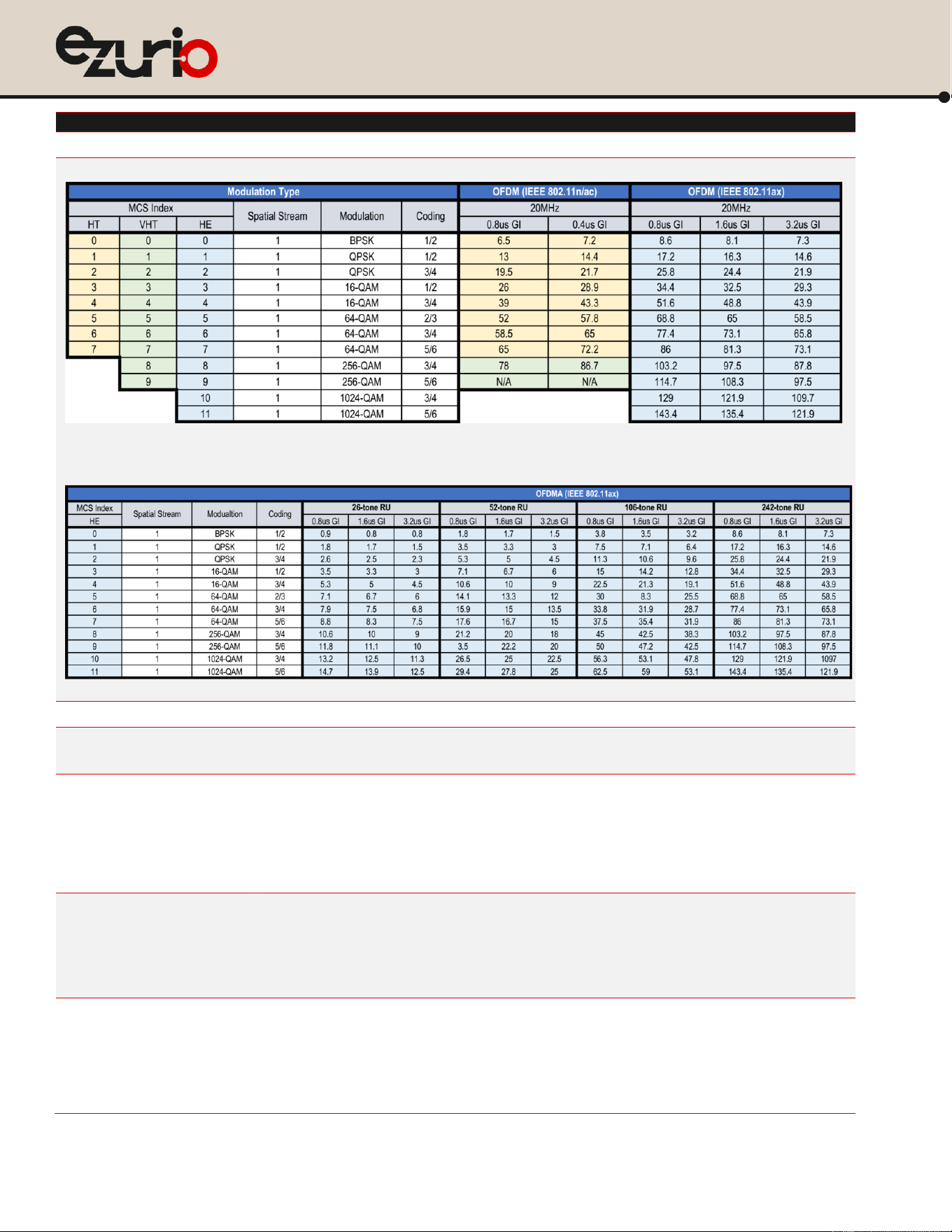
Support 802.11 ax/ac/a/b/g/n 1x1 MU-MIMO.
802.11b (DSSS, CCK) 1, 2, 5.5, 11 Mbps
802.11a/g (OFDM) 6, 9, 12, 18, 24, 36, 48, 54 Mbps
802.11n (OFDM, HT20, MCS0-7)
802.11ac (OFDM, VHT20, MCS0-8)
802.11ax (2.4 GHz / OFDM / HE20 / MCS0-11; 2.4 GHz / OFDMA / HE20 / MCS0-11)
802.11ax (5 GHz, 6 GHz / OFDM / HE20 / MCS0-11; 5 GHz, 6 GHz / OFDMA / HE20 / MCS0-11)
https://www.ezurio.com/
8
© Copyright 2025 Ezurio
All Rights Reserved
Veda IF913
Datasheet
Feature
Description
Modulation Table
BPSK, QPSK, CCK, 16-QAM, 64-QAM, 256-QAM, 1024-QAM
802.11ax/ac/n Spatial Streams
1 (1x1 MU-MIMO)
Bluetooth Modulation
GFSK @ 1, 2 Mbps
GFSK @ 125, 500 Kbps
Regulatory Certifications
United States (FCC)
EU - Member countries of European Union (ETSI)
Great Britain (UKCA)
Canada (ISED)
Australia/New Zealand (RCM)
Japan (MIC)
2.4 GHz Frequency Bands
EU: 2.4 GHz to 2.483 GHz
FCC/ISED: 2.4 GHz to 2.473 GHz
UKCA: 2.4 GHz to 2.483 GHz
MIC: 2.4 GHz to 2.483 GHz
RCM: 2.4 GHz to 2.483 GHz
5 GHz Frequency Bands
EU
5.15 GHz to 5.35 GHz
5.47 GHz to 5.725 GHz
5.725 GHz to 5.85 GHz
FCC
5.15 GHz to 5.35 GHz
5.47 GHz to 5.725 GHz

https://www.ezurio.com/
9
© Copyright 2025 Ezurio
All Rights Reserved
Veda IF913
Datasheet
Feature
Description
5.725 GHz to 5.85 GHz
ISED
5.15 GHz to 5.35 GHz
5.47 GHz to 5.725 GHz
5.725 GHz to 5.85 GHz
UKCA
5.15 GHz to 5.35 GHz
5.47 GHz to 5.730 GHz
5.725 GHz to 5.850 GHz
MIC
5.15 GHz to 5.35 GHz
5.47 GHz to 5.725 GHz
RCM
5.15 GHz to 5.35 GHz
5.47 GHz to 5.725 GHz
5.725 GHz to 5.85 GHz
6 GHz Frequency Bands
FCC / ISED
UNII-5, 5.925 GHz to 6.415 GHz
UNII-6, 6.435 GHz to 6.515 GHz
UNII-7, 6.535 GHz to 6.875 GHz
UNII-8, 6.895 GHz to 7.115 GHz
EU
UNII-5, 5.945 GHz to 6.425 GHz
UKCA
UNII-5, 5.945 GHz to 6.425 GHz
MIC
UNII-5, 5.945 GHz to 6.425 GHz
RCM
UNII-5, 5.945 GHz to 6.425 GHz
Transmit Power
Note: Transmit power on each
channel varies per individual
country regulations. All values are
nominal with +/-2 dBm tolerance at
room temperature.
Tolerance could be up to +/-2.5
dBm across operating
temperature.
Note:
HT20/VHT20/HE20 –
20 MHz-wide channels
802.11a
6 Mbps
17 dBm (50.11 mW)
54 Mbps
16.5 dBm (44.66 mW)
802.11b
1 Mbps
18 dBm (63.09 mW)
11 Mbps
18 dBm (63.09 mW)
802.11g
6 Mbps
18 dBm (63.09 mW)
54 Mbps
17 dBm (50.11 mW)
802.11n (2.4 GHz)
HT20; MCS0-4
HT20; MCS5-7
18 dBm (63.09 mW)
16 dBm (39.81 mW)
802.11ax (2.4 GHz)
HE20; MCS0-4
HE20; MCS5-7
HE20; MCS8-9
HE20; MCS13
18 dBm (63.09 mW)
16 dBm (39.81 mW)
14 dBm (25,11 mW)
10.5 dBm (19.95 mW)
802.11n (5 GHz)
HT20; MCS0-4
HT20; MCS5-7
17 dBm (50.11 mW)
16.5 dBm (44.66 mW)
https://www.ezurio.com/
10
© Copyright 2025 Ezurio
All Rights Reserved
Veda IF913
Datasheet
Feature
Description
802.11ac (5 GHz)
VHT20; MCS0-4
VHT20; MCS5-7
VHT20; MCS8
17 dBm (50.11 mW)
16.5 dBm (44.66 mW)
14 dBm (25.12 mW)
802.11ax (5 GHz)
HE20; MCS0-4
HE20; MCS5-7
HE20; MCS8-9
HE20; MC10-11
17 dBm (50.11 mW)
16.5 dBm (44.66 mW)
14 dBm (25.12 mW)
13 dBm (19.95 mW)
802.11ax (6 Hz, UNII-5 / 6)
11a; 6M-24M
HE20; MCS0-4
HE20; MCS5-7
HE20; MCS8-9
HE20; MCS10-11
15.5 dBm (35.48 mW)
15.5 dBm (35.48 mW)
15 dBm (31.62 mW)
13.5 dBm (22.38 mW)
12 dBm (15.85 mW)
802.11ax (6 Hz, UNII-7 / 8)
11a; 6M-24M
HE20; MCS0-4
HE20; MCS5-7
HE20; MCS8-9
HE20; MCS10-11
15 dBm (31.62 mW)
15 dBm (31.62 mW)
13 dBm (19.95 mW)
12 dBm (15.85 mW)
10.5 dBm (11.22 mW)
Bluetooth
LE (1 Mbps, 2 Mbps)
LE-LR (S=2, S=8)
7 dBm (5.01 mW) , Maximum
7 dBm (5.01 mW) , Maximum
Typical Receiver Sensitivity
(PER <= 10%)
Note: All values nominal, +/-2 dBm.
802.11a:
6 Mbps
-92 dBm
54 Mbps
-75 dBm
802.11b:
1 Mbps
-97 dBm (PER < 8%)
11 Mbps
-90 dBm (PER < 8%)
802.11g:
6 Mbps
-94 dBm
54 Mbps
-77 dBm
802.11n (2.4 GHz)
6.5 Mbps (MCS0; HT20)
-94 dBm
65 Mbps (MCS7; HT20)
-75 dBm
802.11ax (2.4 GHz)
7.3 Mbps (MCS0; HE20)
121.9 Mbps (MCS11; HE20)
7.3 Mbps (MCS0; HE20/RU242)
-94 dBm
-64 dBm
-94 dBm
802.11n (5 GHz)
6.5 Mbps (MCS0; HT20)
-92 dBm
65 Mbps (MCS7; HT20)
-73 dBm
802.11ac (5 GHz)
6.5 Mbps (MCS0; VHT20)
-92 dBm
78 Mbps (MCS8; VHT20)
-70 dBm
802.11ax (5 GHz)
7.3 Mbps (MCS0; HE20)
121.9 Mbps (MCS11; HE20)
7.3 Mbps (MCS0; HE20/RU242)
-92 dBm
-61 dBm
-92 dBm
802.11ax (6 GHz, UNII-5)
6 Mbps
24 Mbps
7.3 Mbps (MCS0; HE20)
-90 dBm
-83 dBm
-90 dBm
https://www.ezurio.com/
11
© Copyright 2025 Ezurio
All Rights Reserved
Veda IF913
Datasheet
Feature
Description
121.9 Mbps (MCS11; HE20)
7.3 Mbps (MCS0; HE20/RU242)
-59 dBm
-90 dBm
802.11ax (6 GHz, UNII-6)
6 Mbps
24 Mbps
7.3 Mbps (MCS0; HE20)
121.9 Mbps (MCS11; HE20)
7.3 Mbps (MCS0; HE20/RU242)
-90 dBm
-82 dBm
-90 dBm
-59 dBm
-90 dBm
802.11ax (6GHz, UNII-7)
6 Mbps
24 Mbps
7.3 Mbps (MCS0; HE20)
121.9 Mbps (MCS11; HE20)
7.3 Mbps (MCS0; HE20/RU242)
-89 dBm
-81 dBm
-89 dBm
-58 dBm
-89 dBm
802.11ax (6 GHz, UNII-8)
6 Mbps
24 Mbps
7.3 Mbps (MCS0; HE20)
121.9 Mbps (MCS11; HE20)
7.3 Mbps (MCS0; HE20/RU242)
-88 dBm
-80 dBm
-88 dBm
-56 dBm
-88 dBm
Bluetooth:
LE-1 Mbps
LE-2 Mbps
LE-LR (S=2)
LE-LR (S=8)
-96 dBm
-94 dBm
-102 dBm
-107 dBm
Operating Systems Supported
ThreadX RTOS
NetX Secure TLS 1.3
NetX Duo (TCP/IP)
Security
WPA, WPA2 (Enterprise) and WPA3 (Enterprise) support for powerful encryption and authentication
Compliance
EU
EN 300 328
EN 301 489-1
EN 301 489-17
EN 301 893
EN 62368-1:2014
EN 300 440
EN 303 687
2011/65/EU (RoHS)
FCC
ISED Canada
47 CFR FCC Part 15.247
47 CFR FCC Part 15.407
47 CFR FCC Part 2.1091
RSS-247
RSS-248
AS/NZS
MIC
AS/NZS 4268:2017
ARIB STD-T66/RCR STD-33 (2.4 GHz)
ARIB STD-T71 (5 GHz)
Article 2 Paragraph 1 of Item 80 :
LPI (ZR), 6 GHz
Certifications
Bluetooth
®
SIG Qualification
TBD
Warranty
One Year Warranty
All specifications are subject to change without notice
https://www.ezurio.com/
12
© Copyright 2025 Ezurio
All Rights Reserved
Veda IF913
Datasheet
5 Block Diagrams
Veda IF913 module Block Diagram
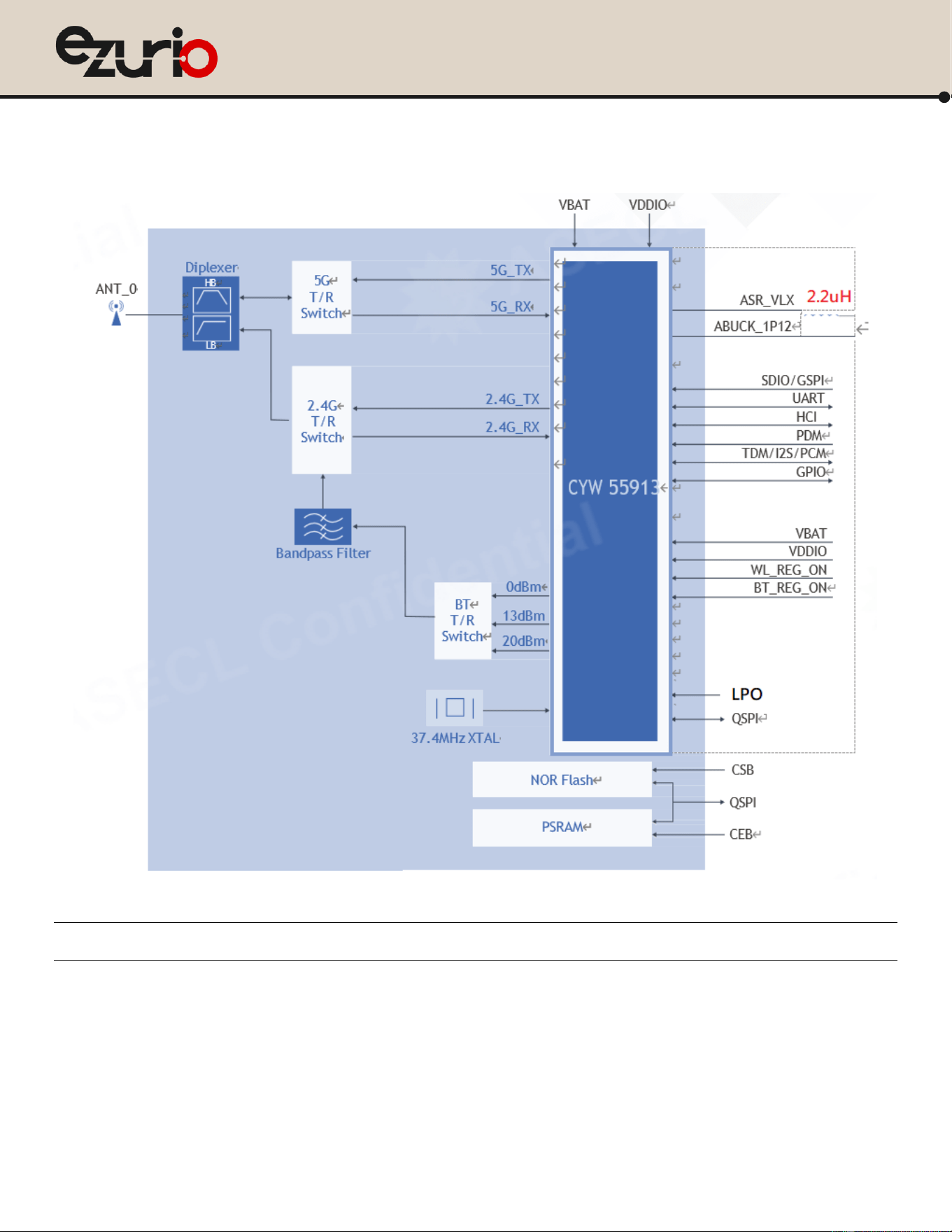
Figure 1: Veda IF913 SIP module block diagram
Note: For embedded memory variant, please connect the QSPI bus outside the SIP. See Veda IF913 Implementation Details.

https://www.ezurio.com/
13
© Copyright 2025 Ezurio
All Rights Reserved
Veda IF913
Datasheet
6 Pin Definitions
Pin #
Name
Type
Voltage
Ref.
Function
Main Chip
Pin out
If Not
Used
1
GND
-
-
Ground
-
GND
2
TDM1_MCK
I/O
VDDIO
TDM1 Interface Master Clock / I2S Master Clock / PCM interface
E2
NC
3
GND
-
-
Ground
-
GND
4
TDM1_SCK
I/O
VDDIO
TDM1 Interface Slave Clock / I2S Interface Clock / PCM interface
E3
NC
5
GND
-
-
Ground
-
GND
6
TDM1_WS
I/O
VDDIO
TDM1 Interface Word Select / I2S Interface Word Select / PCM interface
D3
NC
7
TDM1_DO
I/O
VDDIO
TDM1 Interface Data Out / I2S Interface Data Out / PCM interface
F3
NC
8
TDM1_DI
I/O
VDDIO
TDM1 Interface Data In / I2S Interface Data In / PCM interface
D4
NC
9
BT_DEV_WAKE
I
VDDIO
Bluetooth Device Wake-up
J3
NC
10
WL_DEV_WAKE
I
VDDIO
WLAN Device Wake-up / Programmable General purpose I/O
J2
NC
11
BT_HOST_WAKE
O
VDDIO
Host wake up
F2
NC
12
GND
-
-
Ground
-
GND
13
DIP_OUT
RF
-
WIFI+BT RF output port 0
-
50 ohm
termina
ted
14
GND
-
-
Ground
-
GND
15
GND
-
-
Ground
-
GND
16
LHL_GPIO_8
I/O
VDDIO
Miscellaneous general purpose GPIO_8
G2
NC
17
LHL_GPIO_9
I/O
VDDIO
Miscellaneous general purpose GPIO_9
H1
NC
18
LHL_GPIO_3
I/O
VDDIO
Miscellaneous general purpose GPIO_3
H5
NC
19
LHL_GPIO_5
I/O
VDDIO
Miscellaneous general purpose GPIO_5
H3
NC
20
GND
-
-
Ground
-
GND
21
LPO_IN
I
VDDIO
External sleep clock input (32.768 KHz)
Note: Needed for Bluetooth® Low Energy to support low power mode.
J5
-
22
GND
-
-
Ground
-
GND
23
WL_HOST_WAKE
O
VDDIO
WLAN HOST WAKE / Programmable General purpose I/O
G10
NC
24
BT_UART_TXD
O
VDDIO
UART Serial Output. Serial data output for the HCI UART interface.
F7
NC
25
GND
-
-
Ground
-
GND
26
ABUCK_1P12
PWR
input
-
Normal 1.12V power input and 0.74V when in sleep mode.
Please connect to the filtered ABUCK voltage. See pin-33 and pin-34.
See 錯誤! 找不到參照來源。.
B8
-
27
ABUCK_1P12
PWR
input
-
-
28
GND
-
-
Ground
-
GND
29
TDM2_MCK
I/O
VDDIO
TDM2 Interface Master Clock / I2S Master Clock/ PCM interface
B1
NC
30
GND
-
-
Ground
-
GND
31
TDM2_SCK
I/O
VDDIO
TDM2 Interface Slave Clock / I2S Interface Clock / PCM interface
A1
NC
32
GND
-
-
Ground
-
GND
33
ASR_VLX
PWR
-
A10
-

https://www.ezurio.com/
14
© Copyright 2025 Ezurio
All Rights Reserved
Veda IF913
Datasheet
outp
ut
Analog Switching Regulator (ABUCK) power stage output.
Please connect to external L-C Filter (2.2uH+ 4.7uF) and connected to
ABUCK_1P12 (pin-26; pin-27)
See 錯誤! 找不到參照來源。
34
ASR_VLX
PWR
outp
ut
-
-
35
GND
-
-
Ground
GND
36
GND
-
-
Ground
-
GND
37
VBAT
PWR
3.3V
Main DC supply voltage for module. Operational: VBAT is 3.0V to 4.8V
• VBAT and VDDIO should not rise 10%–90% faster than 40
microseconds.
• VBAT should be up before or at the same time as VDDIO. VDDIO
should NOT be present first or be held high before VBAT is high.
B10/C10/D
10
-
38
VBAT
PWR
3.3V
-
39
GND
-
-
Ground
-
GND
40
SDIO_CLK
I
VDDIO
SDIO Clock Input / gSPI Clock Interface
A7
NC
41
GND
-
-
Ground
-
GND
42
SDIO_CMD
I/O
VDDIO
SDIO Command Line/ gSPI MOSI Interface
A6
NC
43
SDIO_DATA_0
I/O
VDDIO
SDIO Data line 0/ gSPI MISO Interface
B6
NC
44
SDIO_DATA_1
I/O
VDDIO
SDIO Data line 1/ gSPI interrupt Interface
B7
NC
45
SDIO_DATA_2
I/O
VDDIO
SDIO Data line 2/ gSPI Interface
This pin is also used for strapping option for SDIO or gSPI.
Default pull during strapping=”H” for SDIO bus; pull it “L” during strapping
for gSPI bus.
C7
NC
46
SDIO_DATA_3
I/O
VDDIO
SDIO Data line 3/ gSPI CS Interface
C6
NC
47
GND
-
-
Ground
-
GND
48
SCLK
I/O
VDDIO
Serial Clock input for embedded memory.
For No embedded memory variant, keep this pin NC.
-
NC
49
GND
-
-
Ground
GND
50
SI
I/O
VDDIO
Serial Data Input / Serial Data Input Output 0 for embedded memory.
For No embedded memory variant, keep this pin NC.
-
NC
51
SIO2
I/O
VDDIO
Serial Data Input / Serial Data Input Output 2 for embedded memory.
For No embedded memory variant, keep this pin NC.
-
NC
52
SIO1
I/O
VDDIO
Serial Data Input / Serial Data Input Output 1 for embedded memory.
For No embedded memory variant, keep this pin NC.
-
NC
53
HOLDB
I/O
VDDIO
Hold Input/Serial Data Input Output 3 for embedded memory.
For No embedded memory variant, keep this pin NC.
-
NC
54
CEB
I
VDDIO
Chip Select input, active low (CE pin for embedded PSRAM)
For No embedded memory variant, keep this pin NC.
-
NC
55
CSB
I
VDDIO
Chip Select input, active low (CS pin for embedded NOR Flash)
For No embedded memory variant, keep this pin NC.
-
NC
56
SMIF_SPHB_DQ0
I/O
VDDIO
SMIF data line 0.
• Connect to external NOR Flash IO0 and external PSRAM SIO[0].
• Connect to SI (pin-50) for embedded Memory variant.
A4
NC
57
SMIF_SPHB_DQ1
I/O
VDDIO
SMIF data line 1.
• Connect to external NOR Flash IO1 and external PSRAM SIO[1].
• Connect to SIO1 (pin-52) for embedded Memory variant.
B4
NC

https://www.ezurio.com/
15
© Copyright 2025 Ezurio
All Rights Reserved
Veda IF913
Datasheet
58
GND
-
-
Ground
-
GND
59
VDDIO
PWR
input
-
1.8 V IO supply for WLAN GPIOs
• VBAT and VDDIO should not rise 10%–90% faster than 40
microseconds.
D6
NC
60
BT_GPIO_0
I/O
VDDIO
Bluetooth® general purpose I/O
F1
NC
61
BT_GPIO_7
I/O
VDDIO
Bluetooth® general purpose I/O
A3
NC
62
BT_GPIO_16
I/O
VDDIO
Bluetooth® general purpose I/O
B3
NC
63
BT_GPIO_17
I/O
VDDIO
Bluetooth® general purpose I/O
C3
NC
64
BT_GPIO_5
I/O
VDDIO
Bluetooth® general purpose I/O
D7
NC
65
BT_GPIO_6
I/O
VDDIO
Bluetooth® general purpose I/O
E6
NC
66
BT_GPIO_3
I/O
VDDIO
Bluetooth® general purpose I/O
E5
NC
67
BT_GPIO_4
I/O
VDDIO
Bluetooth® general purpose I/O
F5
NC
68
BT_GPIO_2
I/O
VDDIO
Bluetooth® general purpose I/O
E4
NC
69
GND
-
-
Ground
-
GND
70
DMIC_DATA
I/O
VDDIO
Digital mic data
E1
NC
71
GND
-
-
Ground
-
GND
72
LHL_GPIO_4
I/O
VDDIO
Miscellaneous general purpose GPIO_4
H4
NC
73
LHL_GPIO_2
I/O
VDDIO
Miscellaneous general purpose GPIO_2
H6
NC
74
LHL_GPIO_6
I/O
VDDIO
Miscellaneous general purpose GPIO_6
G1
NC
75
GND
-
-
Ground
-
GND
76
GND
-
-
Ground
-
GND
77
MIC_P
I
VDDIO
ADC microphone positive input
E8
NC
78
GND
-
-
Ground
-
GND
79
BT_UART_RXD
I
VDDIO
UART Serial Input. Serial data input for the HCI UART interface.
G6
NC
80
BT_UART_RTS_N
O
VDDIO
UART request-to-send. Active-low request-to-send signal for the HCI UART
interface. Bluetooth® LED control pin.
G7
NC
81
BT_UART_CTS_N
I
VDDIO
UART clear-to-send. Active-low clear-to-send signal for the HCI UART
interface.
F6
NC
82
BT_REG_ON
I
VDDIO
Used by the PMU to power up or power down the internal regulators
used by the Bluetooth® section. When deasserted, this pin holds the
Bluetooth® section in reset. This pin has an internal 50 kΩ pull-down
resistor by default. that is auto enabled/disabled by programming.
C8
-
83
WL_REG_ON
I
VDDIO
Not used for IF913/IF912.
This should be tied to GND on board.
A8
GND
84~86
GND
-
-
Ground
-
GND
87
TDM2_DI
I/O
VDDIO
TDM2 Interface Data In / I2S Interface Data In / PCM interface
D2
NC
88
TDM2_DO
I/O
VDDIO
TDM2 Interface Data Out / I2S Interface Data Out / PCM interface
C1
NC
89
TDM2_WS
I/O
VDDIO
TDM2 Interface Word Select / I2S Interface Word Select / PCM interface
A2
NC
90
VCC
PWR
-
Memory 1.8V power supply
-
-
91
GND
-
-
Ground
-
GND
92
SMIF_SPHB_CLK
O
VDDIO
SMIF clock output
A5
GND

https://www.ezurio.com/
16
© Copyright 2025 Ezurio
All Rights Reserved
Veda IF913
Datasheet
• Connect to external NOR Flash SCK and external PSRAM SCK.
• Connect to SCK (pin-48) for embedded Memory variant.
93
GND
-
-
Ground
-
GND
94
SMIF_SPHB_DQ2
I/O
VDDIO
SMIF data line 2.
• Connect to external NOR Flash IO2 and external PSRAM SIO[2].
• Connect to SIO2 (pin-51) for embedded Memory variant.
B5
-
95
SMIF_SPHB_DQ3
I/O
VDDIO
SMIF data line 3.
• Connect to external NOR Flash IO3 and external PSRAM SIO[3].
• Connect to HOLD (pin-53) for embedded Memory variant.
C5
NC
96
SMIF_SPHB_
CS0_N
O
VDDIO
SMIF chip select0 active-low output
• Connect to external NOR Flash CS# pin.
• Connect to CSB (pin-55) for embedded Memory variant.
C4
NC
97
SMIF_SPHB_
CS1_N
O
VDDIO
SMIF chip select1 active-low output
• Connect to external PSRAM CE# pin.
• Connect to CEB (pin-54) for embedded Memory variant.
G3
NC
98~107
GND
-
-
Ground
-
GND
108
DMIC_CLK
I/O
VDDIO
Digital mic clock
D1
NC
E1~E4
GND
-
-
Ground
GND
https://www.ezurio.com/
17
© Copyright 2025 Ezurio
All Rights Reserved
Veda IF913
Datasheet
7 Veda IF913 Implementation Details
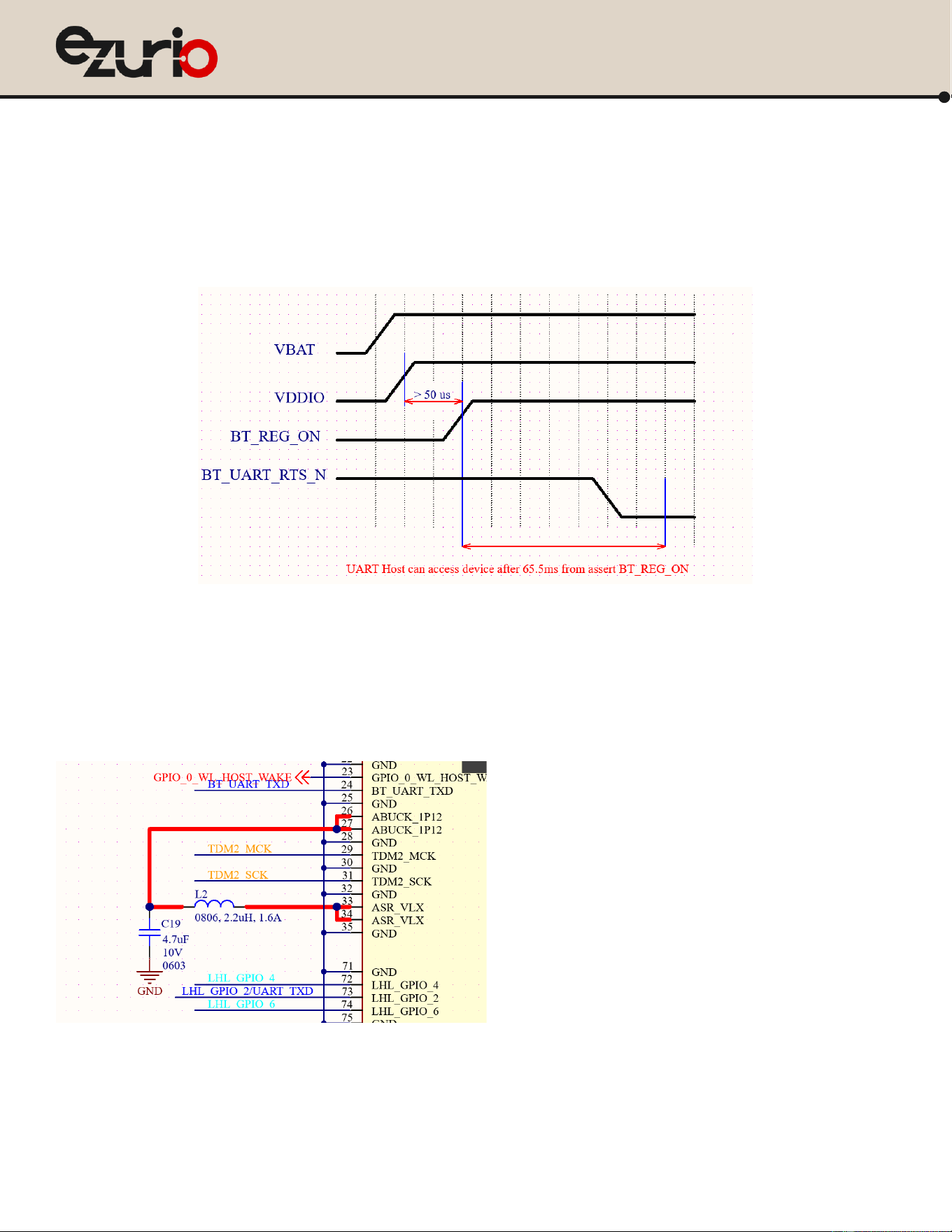
Power up sequency timing
To maintain stable MCU and Bluetooth starting up, below power up sequency timing is required.
• VBAT and VDDIO should not rise 10%–90% faster than 40 microseconds.
• VBAT should be up before or at the same time as VDDIO. VDDIO should NOT be present first or be held high before VBAT is high.
L-C filter for Buck switching regulator
An Analog Switching Regulator (ASR or ABUCK) is built in the Veda IF913 module, the ABUCK output is brought out to pin-33 and pin-34. A L-C filter (2.2uH and 4.7uF)
is required to filter out the switching noise before it feeds into ABUCK_1P12 (pin-26 and pin-27). Keep the 2.2uH and 4.7uF as close to Veda IF913 as possible to keep
the current flow loop small as you can. Please refer to the Ezurio DVK for the detail placement and routing. Detail parts information is shown in below.
• 2.2uH: 74479276222C (Wurth Elektronik)
• 4.7uF: GRM188C71A475KE11# (Murata)
https://www.ezurio.com/
18
© Copyright 2025 Ezurio
All Rights Reserved
Veda IF913
Datasheet
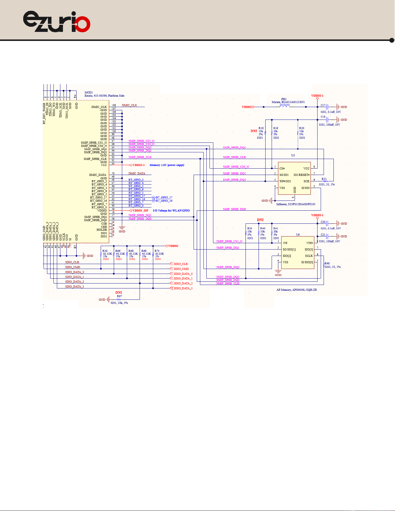
Serial Memory Interface (SMIF) Connection.
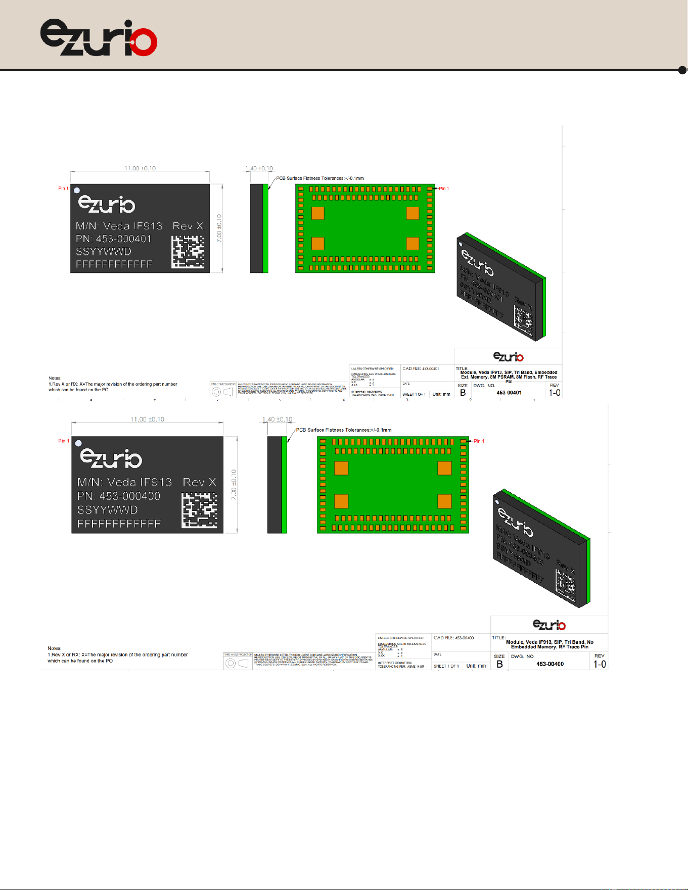
• For the Veda IF913 without embedded memory variant (453-00400R), user can add external memory (NOR Flash and PSRAM) to the SMIF. Example
connections are shown below. Note: VDDIO is limited to 1.8V.
https://www.ezurio.com/
19
© Copyright 2025 Ezurio
All Rights Reserved
Veda IF913
Datasheet
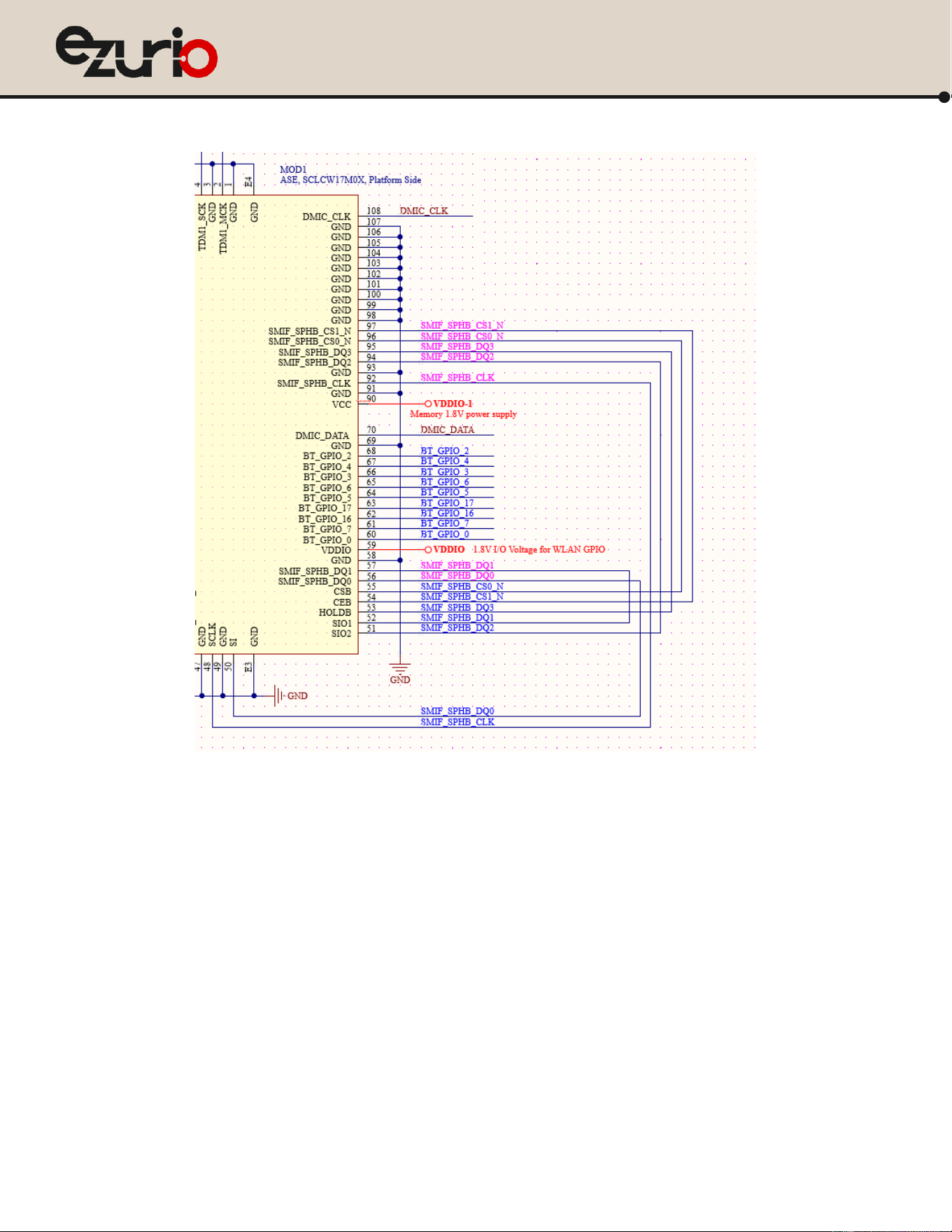
• For the Veda IF913 with embedded memory variant (453-00401R), user need to connect SMIF to the embedded memory pin out (pin48/50; pin51 to pin-55).
Example connections are shown below.

https://www.ezurio.com/
20
© Copyright 2025 Ezurio
All Rights Reserved
Veda IF913
Datasheet
SDIO and gSPI strapping configuration
SDIO and gSPI in Veda IF913 are muxed together on the same pin out, please reference the pin definition table.
A strapping option pin SDIO_DATA[2] is used to configure between SDIO and gSPI. Default is in “H” state which is SDIO mode. Pull this pin to “L” will be set in gSPI
mode.
7.1.1 SDIO mode
Veda IF913provide support for SDIO V 3.0, including the new UHS-I modes:
• DS: Default speed (DS) up to 25 MHz, including 1 and 4-bit modes (1.8 V signaling)
• HS: High-speed up to 50 MHz (1.8 V signaling)
• SDR12: SDR up to 25 MHz (1.8 V signaling)
• SDR25: SDR up to 50 MHz (1.8 V signaling)
• SDR50: SDR up to 100 MHz (1.8 V signaling)
• DDR50: DDR up to 50 MHz (1.8 V signaling)
Notes: 1. The UHS-1 rate SDR104, that is part of the SDIO V 3.0 specification, is not supported.
2. Veda IF913 is backward compatible with SDIO V 2.0 host interfaces. Note however that it can only support 1.8 V signaling. It cannot support 3.3 V
signaling during initialization post power cycle and in default/high speed SDIO V 2.0 modes. The host must use 1.8 V signaling.
According to the SDIO specification, pull-ups in the 10 kΩ to 100 kΩ range are required on the four DATA lines and the CMD line. This requirement must
be met during all operating states either through the use of external pull-up resistors or through proper programming of the SDIO host’s internal pull-
ups.
7.1.2 gSPI mode
Veda IF913 has the option of using the simplified generic SPI (gSPI) interface/protocol.
Characteristics of the gSPI mode include:
• Up to 50-MHz operation
• Fixed delays for responses and data from the device
• Alignment to host gSPI frames (16 or 32 bits)
• Up to 2-KB frame size per transfer
• Little-endian and big-endian configurations
• A configurable active edge for shifting
• Packet transfer for CCM/CP Traffic/Data Exchange
Note: gSPI mode is enabled using the strapping option pins
https://www.ezurio.com/
21
© Copyright 2025 Ezurio
All Rights Reserved
Veda IF913
Datasheet
MHF4 and Embedded PCB antenna
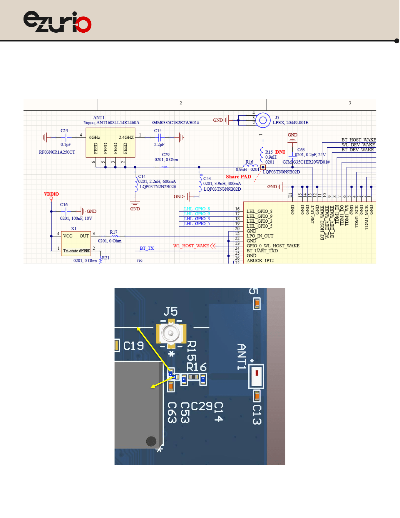
The Veda IF913 DVK design has two antenna connection options which are MHF4 and embedded PCB antenna. Pop on R15, users can get the RF signal out at MHF4
connector for external antenna. Pop on R16 will allow users to use the embedded PCB antenna.
Please copy the components’ location for the RF trace from the DVK to maintain the RF performance and adopt Ezurio certification grant.
R15
R16
https://www.ezurio.com/
22
© Copyright 2025 Ezurio
All Rights Reserved
Veda IF913
Datasheet
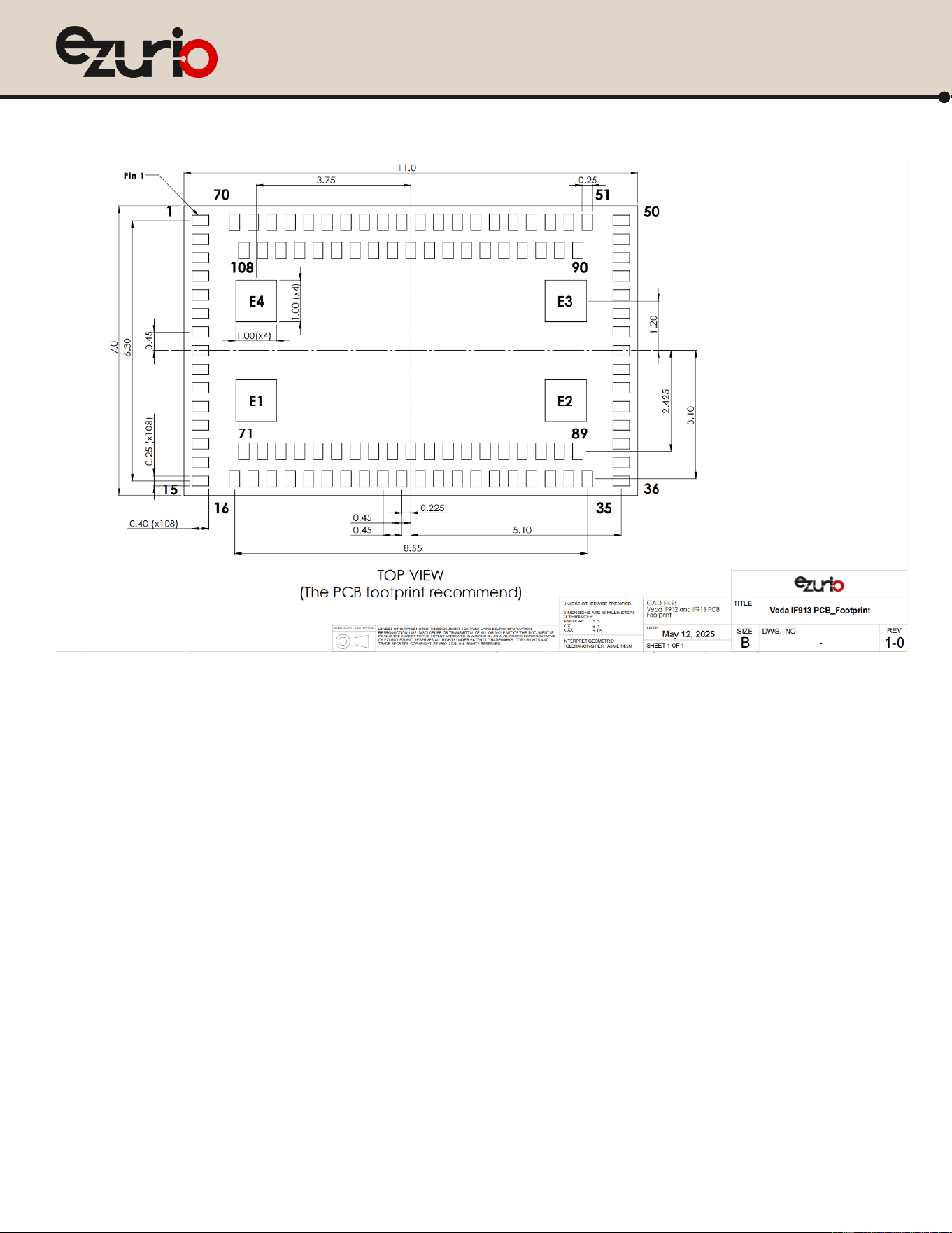
8 PCB footprint
https://www.ezurio.com/
24
© Copyright 2025 Ezurio
All Rights Reserved
Veda IF913
Datasheet
https://www.ezurio.com/
25
© Copyright 2025 Ezurio
All Rights Reserved
Veda IF913
Datasheet
10 Material handling information
Required Storage Conditions
10.1.1 Prior to Opening the Dry Packing
The following are required storage conditions prior to opening the dry packing:
• Normal temperature: 5~40˚C
• Normal humidity: 80% (Relative humidity) or less
• Storage period: One year or less
Note: Humidity means relative humidity.
10.1.2 After Opening the Dry Packing
The following are required storage conditions after opening the dry packing (to prevent moisture absorption):
• Storage conditions for one-time soldering:
– Temperature: 5-25°C
– Humidity: 60% or less
– Period: 72 hours or less after opening
• Storage conditions for two-time soldering
– Storage conditions following opening and prior to performing the 1
st
reflow:
• Temperature: 5-25°C
• Humidity: 60% or less
• Period: A hours or less after opening
– Storage conditions following completion of the 1
st
reflow and prior to performing the 2
nd
reflow
• Temperature: 5-25°C
• Humidity: 60% or less
• Period: B hours or less after completion of the 1st reflow
Note: Should keep A+B within 72 hours.
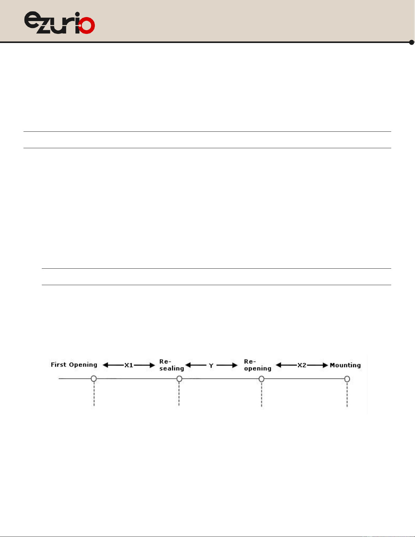
10.1.3 Temporary Storage Requirements after Opening
The following are temporary storage requirements after opening:
• Only re-store the devices once prior to soldering.
• Use a dry box or place desiccant (with a blue humidity indicator) with the devices and perform dry packing again using vacuumed heat-sealing.
The following indicate the required storage period, temperature, and humidity for this temporary storage:
• Storage temperature and humidity:
*** - External atmosphere temperature and humidity of the dry packing
• Storage period:
– X1+X2 – Refer to Material handling information
– Required Storage Conditions. Keep is X1+X2 within 72 hours.
– Y – Keep within two weeks or less.
Baking Conditions
Baking conditions and processes for the module follow the J-STD-033 standard which includes the following:
Temperature: +5 to +40°C
Humidity: 80% or less
Temperature: +5 to +25°C
Humidity: 60% or less
Temperature: +5 to +40°C
Humidity: 80% or less
Temperature: +5 to +25°C
Humidity: 60% or less
***
***

https://www.ezurio.com/
26
© Copyright 2025 Ezurio
All Rights Reserved
Veda IF913
Datasheet
• The calculated shelf life in a sealed bag is 12 months at <40℃ and <80% relative humidity.
• Once the packaging is opened, the SiP must be mounted (per MSL4/Moisture Sensitivity Level 4) within 72 hours at <30˚C and <60% relative humidity.
If the SiP is not mounted within 72 hours or if, when the dry pack is opened, the humidity indicator card displays >10% humidity, then the product must be baked for
48 hours at 125 ˚C (±5 ˚C).
https://www.ezurio.com/
27
© Copyright 2025 Ezurio
All Rights Reserved
Veda IF913
Datasheet
11 Surface Mount Conditions
The following soldering conditions are recommended to ensure device quality.
Recommended Stencil Aperture
TBD
Figure 2: Veda IF913 SIP stencil aperture
Note: The stencil thickness is 0.12mm.
Soldering profile
Note: When soldering, the stencil thickness should be 0.12 mm.
Convection reflow or IR/Convection reflow (one-time soldering or two-time soldering in air or nitrogen environment)
Measuring point – IC package surface
Temperature profile:
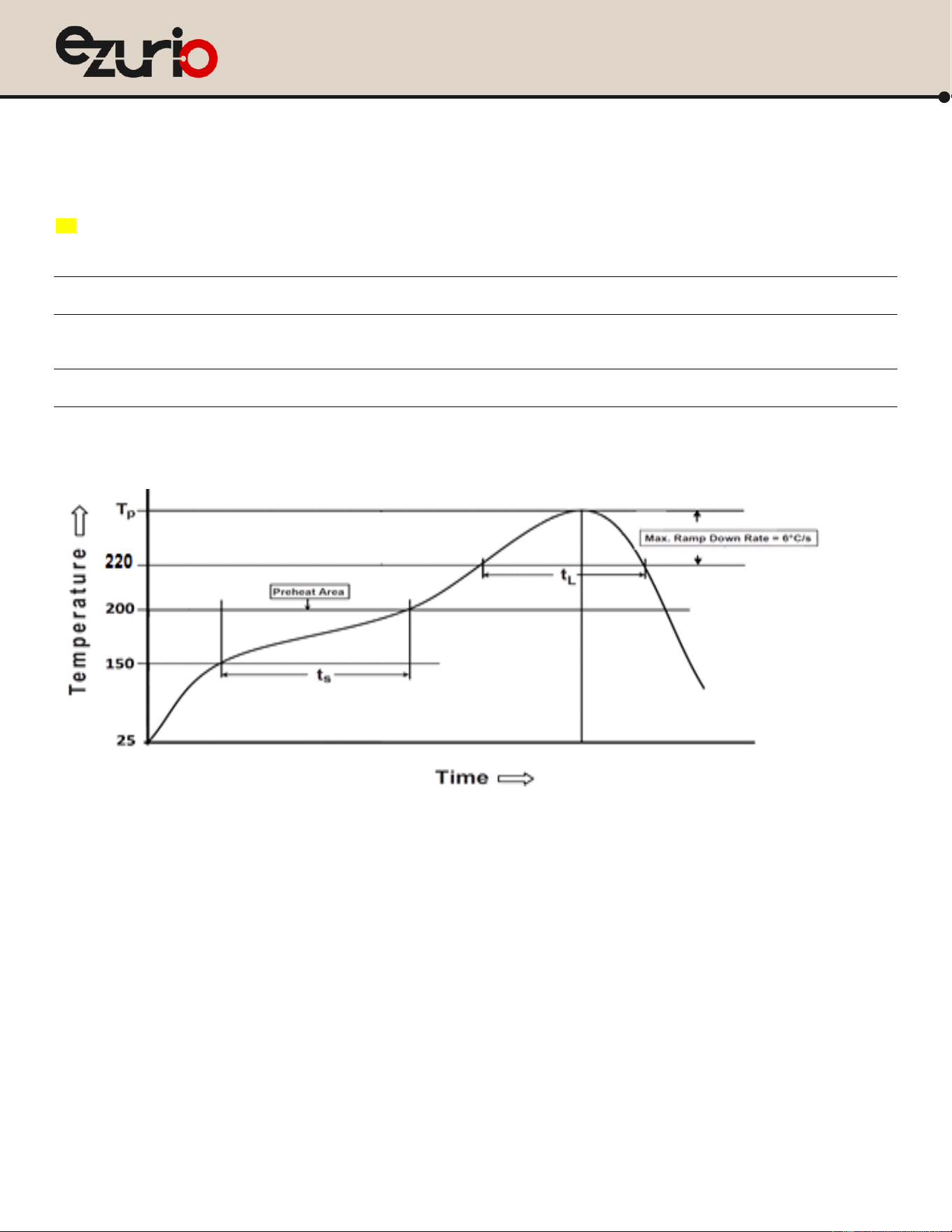
Figure 3: Temperature profile
• Solder paste alloy: SAC305(Sn96.5 / Ag3.0 / Cu 0.5)
• Pre-heat temperature: 150℃ ~ 200℃; Soak time: 60 second ~ 120 second
• Peak temperature: 235℃ ~ 250℃
• Time above 220℃: 40 second ~ 90 second
• Optimal cooling rate < 3℃/second
• The oxygen concentration < 2000 ppm
https://www.ezurio.com/
28
© Copyright 2025 Ezurio
All Rights Reserved
Veda IF913
Datasheet
12 Cautions When Removing the SIP from the Platform for RMA
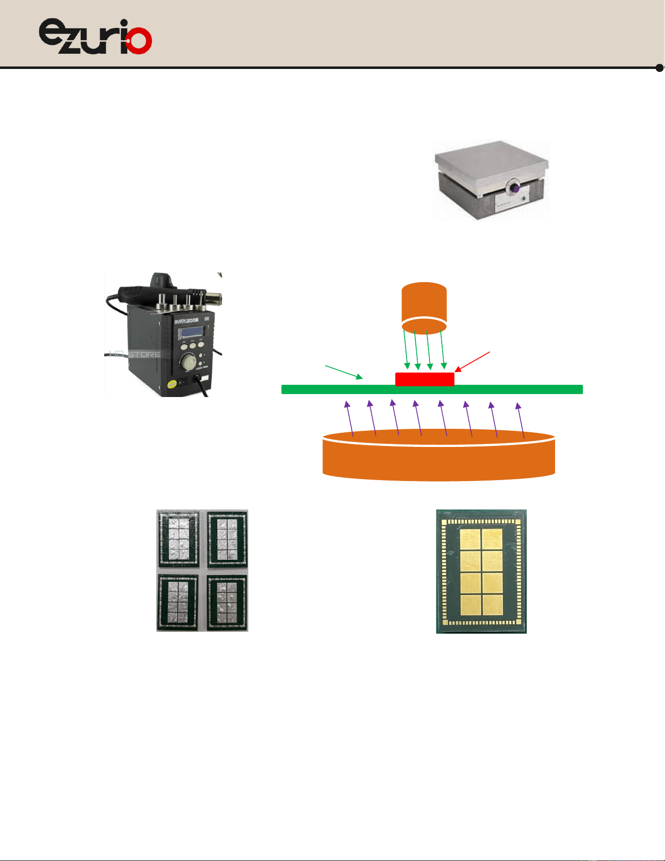
• Bake the platform PCBA before removing the Veda IF913 module from the platform..
• Remove the Sona IF513 module by using a hot air gun. This process should be carried out by a skilled technician.
Recommended conditions:
• One-side component platform:
– Set the hot plate at 280°C.
– Put the platform on the hot plate for 8~10 seconds.
– Remove the device from platform.
• Two-side components platform:
– Use two hot air guns.
– On the bottom, use a pre-heated nozzle (temp setting of 200~250°C) at a suitable distance from the platform PCB.
– On the top, apply a remove nozzle (temp setting of 330°C). Heat until device can be removed from platform PCB.
• Remove the residue solder under the bottom side of device. (Note: Alternate module pictured as an example)
(Not accepted for RMA)
(Accepted for RMA analysis)
Figure 4: Example module with residue solder on the bottom
Figure 5: module without residue solder
• Remove and clean the residue flux as needed.
12.1.1 Precautions for Use
• Opening/handling/removing must be done on an anti-ESD treated workbench. All workers must also have undergone anti-ESD treatment.
• The devices should be mounted within one year of the date of delivery.
• The Veda IF913 modules are MSL level 4 rated.
Platform PCB
SIP
Remove Nozzle
Pre-heat Nozzle
https://www.ezurio.com/
29
© Copyright 2025 Ezurio
All Rights Reserved
Veda IF913
Datasheet
13 Certified Antennas
The Veda IF913 module was tested with antennas listed in the following table. The OEM can choose a different manufacturer’s antenna but must make sure it is of
same type and that the gain is less than or equal to the antenna that is approved for use.
Manufacturer
Model
Ezurio
Part Number
Type
Connector
Peak Gain (dBi)
2.4GHz
5GHz
6GHz
Ezurio (formerly Laird
Connectivity)
FlexMIMO 6E
EFD2471A3S-10MH4L
PIFA
MHF4L
2.2
3.8
3.3
Ezurio (formerly Laird
Connectivity)
FlexPIFA 6E
EFB2471A3S-10MH4L
PIFA
MHF4L
2.2
3.9
3.8
Ezurio (formerly Laird
Connectivity)
Mini NanoBlade Flex 6
GHz
EMF2471A3S-10MH4L
PCB Dipole
MHF4L
2.4
4.4
5.2
Joymax Electronics
Dipole 6E
TWX-100BRSAX-2001 / TWX-
100BRS3B
Dipole
RP-SMA
2.0
4.0
4.0
Ezurio (formerly Laird
Connectivity)
FlexPIFA Dual Band
001-0021
PIFA
IPEX MHF4L
2.5
3.0
3.0
Ezurio (formerly Laird
Connectivity)
FlexPIFA Dual Band
EFB2455A3S-15MH4L
PIFA
MHF1
2.5
3.0
3.0
Yageo (Pulse)
ANT1608LL14R2460A
Chip
Antenna
2.3
2.7
3.3

https://www.ezurio.com/
30
© Copyright 2025 Ezurio
All Rights Reserved
Veda IF913
Datasheet
14 Regulatory
14.1 Federal Communication Commission Interference Statement
This equipment has been tested and found to comply with the limits for a Class B digital device, pursuant to Part 15 of the FCC Rules. These limits are designed to
provide reasonable protection against harmful interference in a residential installation. This equipment generates, uses and can radiate radio frequency energy and, if
not installed and used in accordance with the instructions, may cause harmful interference to radio communications. However, there is no guarantee that interference
will not occur in a particular installation. If this equipment does cause harmful interference to radio or television reception, which can be determined by turning the
equipment off and on, the user is encouraged to try to correct the interference by one of the following measures:
- Reorient or relocate the receiving antenna.
- Increase the separation between the equipment and receiver.
- Connect the equipment into an outlet on a circuit different from that to which the receiver is connected.
- Consult the dealer or an experienced radio/TV technician for help.
FCC Caution: Any changes or modifications not expressly approved by the party responsible for compliance could void the user's authority to operate this equipment.
This device complies with Part 15 of the FCC Rules. Operation is subject to the
following two conditions: (1) This device may not cause harmful interference, and (2) this device must accept any interference received, including interference that may
cause undesired operation.
IMPORTANT NOTE:
FCC Radiation Exposure Statement:
This equipment complies with FCC radiation exposure limits set forth for an uncontrolled environment. This equipment should be installed and operated with minimum
distance 20cm between the radiator & your body.
This transmitter must not be co-located or operating in conjunction with any other antenna or transmitter.
Country Code selection feature to be disabled for products marketed to the US/CANADA.
Operation of this device is restricted to indoor use only
Transmitters in the 5.925-7.125 GHz band are prohibited from operating to control or communicate with unmanned aircraft systems.
Integration instructions for host product manufacturers
Applicable FCC rules to module
FCC Part 15.247
Summarize the specific operational use conditions
This device is intended only for OEM integrators under the following conditions:
1) The transmitter module may not be co-located with any other transmitter or antenna
As long as 1 condition above are met, further transmitter test will not be required. However, the OEM integrator is still responsible for testing their
end-product for any additional compliance requirements required with this module installed.
IMPORTANT NOTE: In the event that these conditions can not be met (for example certain laptop configurations or co-location with another
transmitter), then the FCC authorization is no longer considered valid and the FCC ID can not be used on the final product. In these circumstances, the
OEM integrator will be responsible for re-evaluating the end product (including the transmitter) and obtaining a separate FCC authorization. The OEM
integrator has to be aware not to provide information to the end user regarding how to install or remove this RF module in the user’s manual of the
end product which integrates this module.
The end user manual shall include all required regulatory information/warning as show in this manual.
Limited module procedures
Not applicable
Trace antenna designs
Not applicable
RF exposure considerations
20 cm separation distance and co-located issue shall be met as mentioned in “Summarize the specific operational use conditions”.
Product manufacturer shall provide below text in end-product manual
“FCC Radiation Exposure Statement:
“This equipment complies with FCC radiation exposure limits set forth for an uncontrolled environment. This equipment should be installed and operated with minimum
distance 20cm between the radiator & your body.”
https://www.ezurio.com/
31
© Copyright 2025 Ezurio
All Rights Reserved
Veda IF913
Datasheet
Antennas
Manufacture / Part Number
Type
Connector
2.4GHz
5GHz
6GH
Ezurio / FlexMIMO 6E
PIFA
MHF4L
2.2
3.8
3.3
Ezurio / FlexPIFA 6E
PIFA
MHF4L
2.2
3.9
3.8
Ezurio / Mini NanoBlade Flex 6GHz
PCB Dipole
MHF4L
2.4
4.4
5.2
Joymax Electronics / Dipole 6E
Dipole
RP-SMA
2
4
4
Ezurio / FlexPIFA Dual Band
PIFA
IPEX MHF4L
2.5
3
Ezurio / FlexPIFA Dual Band
PIFA
MHF1
2.5
3
Yageo / Chip Antenna
Chip
NA
2.3
0.1
2.7
Label and Compliance Information
Product manufacturers need to provide a physical or e-label stating
“Contains FCC ID: SQG-VEDAIF913” with finished product
Information on Test Modes and Additional Testing Requirements
Wi-Fi Test tool: GNOME Terminal, Version: 3.52.0 / BT Test tool: AIROC, Version: 1.2.0.2890 shall be used to set the module to transmit
continuously.
Additional Testing, Part 15 Subpart B Disclaimer
The module is only FCC authorized for the specific rule parts listed on the grant, and that the host product manufacturer is responsible for
compliance to any other FCC rules that apply to the host not covered by the modular transmitter grant of certification. The final host product still
requires Part 15 Subpart B compliance testing with the modular transmitter installed
14.2 Industry Canada statement
This device contains licence-exempt transmitter(s)/receiver(s) that comply with Innovation, Science and Economic Development Canada’s licence-exempt RSS(s).
Operation is subject to the following two conditions:
(1) This device may not cause interference
(2) This device must accept any interference, including interference that may cause undesired operation of the device
L’émetteur/récepteur exempt de licence contenu dans le présent appareil est conforme aux CNR d’Innovation, Sciences et Développement économique Canada
applicables aux appareils radio exempts de licence. L’exploitation est autorisée aux deux conditions suivantes :
(1) L’appareil ne doit pas produire de brouillage;
(2) L’appareil doit accepter tout brouillage radioélectrique subi, même si le brouillage est susceptible d’en compromettre le fonctionnement.
Radiation Exposure Statement:
This equipment complies with Canada radiation exposure limits set forth for an uncontrolled environment. This equipment should be installed and operated with
minimum distance 20cm between the radiator & your body.
Déclaration d'exposition aux radiations:
Cet équipement est conforme Canada limites d'exposition aux radiations dans un environnement non contrôlé. Cet équipement doit être installé et utilisé à distance
minimum de 20cm entre le radiateur et votre corps.
Devices shall not be used for control of or communications with unmanned aircraft systems.
Devices shall not be used on oil platforms.
Devices shall not be used on aircraft, except for the low-power indoor access points, indoor subordinate devices, low-power client devices, and very low-power
devices operating in the 5925-6425 MHz band, that may be used on large aircraft as defined in the Canadian Aviation Regulations, while flying above 3,048 meters
(10,000 feet).

https://www.ezurio.com/
32
© Copyright 2025 Ezurio
All Rights Reserved
Veda IF913
Datasheet
Devices shall not be used on automobiles.
Devices shall not be used on trains.
Devices shall not be used on maritime vessels.
Les dispositifs ne doivent pas être utilisés pour commander des systèmes d’aéronef sans pilote ni pour communiquer avec de tels systèmes;
Les dispositifs ne doivent pas être utilisés sur les plateformes de forage pétrolier;
Les dispositifs ne doivent pas être utilisés dans les aéronefs, à l'exception des points d'accès intérieurs de faible puissance, des dispositifs subordonnés intérieurs, des
dispositifs clients de faible puissance et des dispositifs de très faible puissance fonctionnant dans la bande de 5 925 à 6 425 MHz, qui peuvent être utilisés dans les
gros aéronefs tel qu’il est défini dans le Règlement de l'aviation canadien, et ce, lorsqu'ils volent à une altitude supérieure à 3 048 mètres (10 000 pieds).
Les dispositifs ne doivent pas être utilisés dans les automobiles;
Les dispositifs ne doivent pas être utilisés dans les trains;
Les dispositifs ne doivent pas être utilisés sur les navires maritimes.
This device is intended only for OEM integrators under the following conditions:
1) The transmitter module may not be co-located with any other transmitter or antenna.
As long as 1 condition above are met, further transmitter test will not be required. However, the OEM integrator is still responsible for testing their end-product for any
additional compliance requirements required with this module installed.
Cet appareil est conçu uniquement pour les intégrateurs OEM dans les conditions suivantes:
1) Le module émetteur peut ne pas être coïmplanté avec un autre émetteur ou antenne.
Tant que les 1 condition ci-dessus sont remplies, des essais supplémentaires sur l'émetteur ne seront pas nécessaires. Toutefois, l'intégrateur OEM est toujours
responsable des essais sur son produit final pour toutes exigences de conformité supplémentaires requis pour ce module installé.
IMPORTANT NOTE:
In the event that these conditions can not be met (for example certain laptop configurations or co-location with another transmitter), then the Canada authorization is
no longer considered valid and the IC ID can not be used on the final product. In these circumstances, the OEM integrator will be responsible for re-evaluating the end
product (including the transmitter) and obtaining a separate Canada authorization.
NOTE IMPORTANTE:
Dans le cas où ces conditions ne peuvent être satisfaites (par exemple pour certaines configurations d'ordinateur portable ou de certaines co-localisation avec un
autre émetteur), l'autorisation du Canada n'est plus considéré comme valide et l'ID IC ne peut pas être utilisé sur le produit final. Dans ces circonstances, l'intégrateur
OEM sera chargé de réévaluer le produit final (y compris l'émetteur) et l'obtention d'une autorisation distincte au Canada.
End Product Labeling
The final end product must be labeled in a visible area with the following: “Contains IC:3147A-VEDAIF913”.
Plaque signalétique du produit final
Le produit final doit être étiqueté dans un endroit visible avec l'inscription suivante: "Contient des IC: 3147A-VEDAIF913".
Manual Information to the End User
The OEM integrator has to be aware not to provide information to the end user regarding how to install or remove this RF module in the user’s manual of the end
product which integrates this module.
The end user manual shall include all required regulatory information/warning as show in this manual.
Manuel d'information à l'utilisateur final
L'intégrateur OEM doit être conscient de ne pas fournir des informations à l'utilisateur final quant à la façon d'installer ou de supprimer ce module RF dans le manuel
de l'utilisateur du produit final qui intègre ce module.
Le manuel de l'utilisateur final doit inclure toutes les informations réglementaires requises et avertissements comme indiqué dans ce manuel.
This radio transmitter [IC: 3147A-VEDAIF913 has been approved by Innovation, Science and Economic Development Canada to operate with the antenna types listed
below, with the maximum permissible gain indicated. Antenna types not included in this list that have a gain greater than the maximum gain indicated for any type
listed are strictly prohibited for use with this device.
Le présent émetteur radio [IC: 3147A-VEDAIF913] a été approuvé par Innovation, Sciences et Développement économique Canada pour fonctionner avec les types
d'antenne énumérés ci-dessous et ayant un gain admissible maximal. Les types d'antenne non inclus dans cette liste, et dont le gain est supérieur au gain maximal
indiqué pour tout type figurant sur la liste, sont strictement interdits pour l'exploitation de l'émetteur.
https://www.ezurio.com/
33
© Copyright 2025 Ezurio
All Rights Reserved
Veda IF913
Datasheet
Antennas
Manufacture / Part Number
Type
Connector
2.4GHz
5GHz
6GH
Ezurio / FlexMIMO 6E
PIFA
MHF4L
2.2
3.8
3.3
Ezurio / FlexPIFA 6E
PIFA
MHF4L
2.2
3.9
3.8
Ezurio / Mini NanoBlade Flex 6GHz
PCB Dipole
MHF4L
2.4
4.4
5.2
Joymax Electronics / Dipole 6E
Dipole
RP-SMA
2
4
4
Ezurio / FlexPIFA Dual Band
PIFA
IPEX MHF4L
2.5
3
Ezurio / FlexPIFA Dual Band
PIFA
MHF1
2.5
3
Yageo / Chip Antenna
Chip
NA
2.3
0.1
2.7
14.3 EU & UKCA Declaration of Conformity
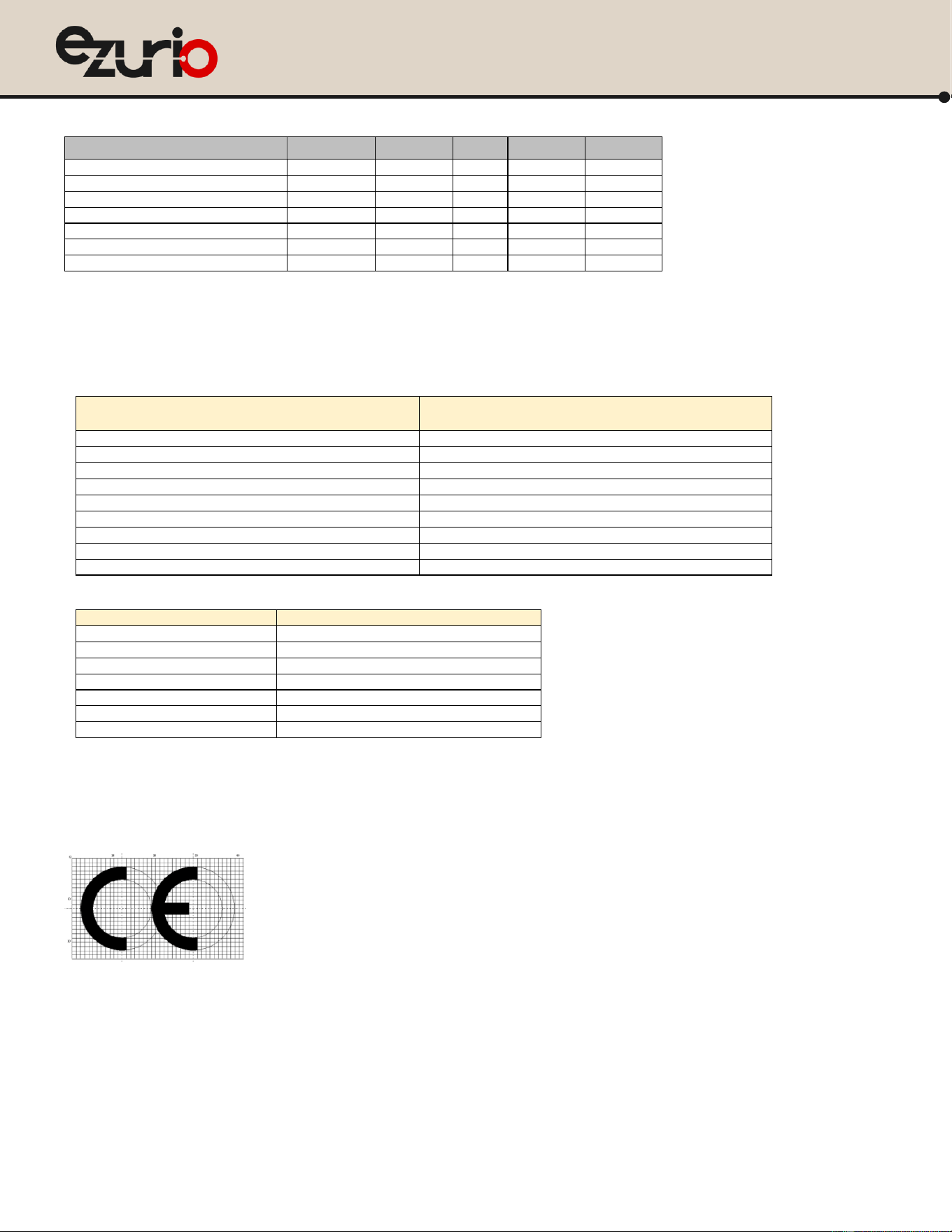
This device complies with the essential requirements of the Radio Equipment directive: 2014 / 53 / EU and Radio Equipment Regulations 2017 (SI 2017/1206). The
following test methods have been applied in order to prove presumption of conformity with the essential requirements of the Radio Equipment directive: 2014 / 53 /
EU and the Radio Equipment Regulations 2017(SI 2017/1206):
Radio Equipment directive: 2014 / 53 / EU
Radio Equipment Regulations 2017(SI 2017/1206)
EN 300 328 v2.2.2
EN 300 328 v2.2.2
EN 301 893 V2.2.1
EN 301 893 V2.2.1
ETSI EN 303 687 V1.1.1
ETSI EN 303 687 V1.1.1
EN IEC 62311:2020
BS EN IEC 62311:2020
EN 50385: 2017
BS EN 50385: 2017
EN 50665: 2017
BS EN 50665: 2017
EN 301 489-1 V2.2.3
EN 301 489-1 V2.2.3
EN 301 489-17 V3.3.1
EN 301 489-17 V3.3.1
EN IEC 62368-1:2020+A11:2020+AC:2020-05
BS EN IEC 62368-1:2020+A11:2020
Wi-Fi Power
Freq. range
Power
BT
10 dBm
2400MHz ~ 2483.5MHz
20 dBm
5150MHz ~ 5250MHz
22 dBm
5250MHz ~ 5350MHz
22 dBm
5470MHz ~ 5725MHz
22 dBm
5725 MHz ~5850MHz
21 dBm
5925MHz ~ 6425MHz
21 dBm
SW version: 6.12.72
RF exposure statement
The minimum distance between the user and/or any bystander and the radiating structure of the transmitter is 20cm.
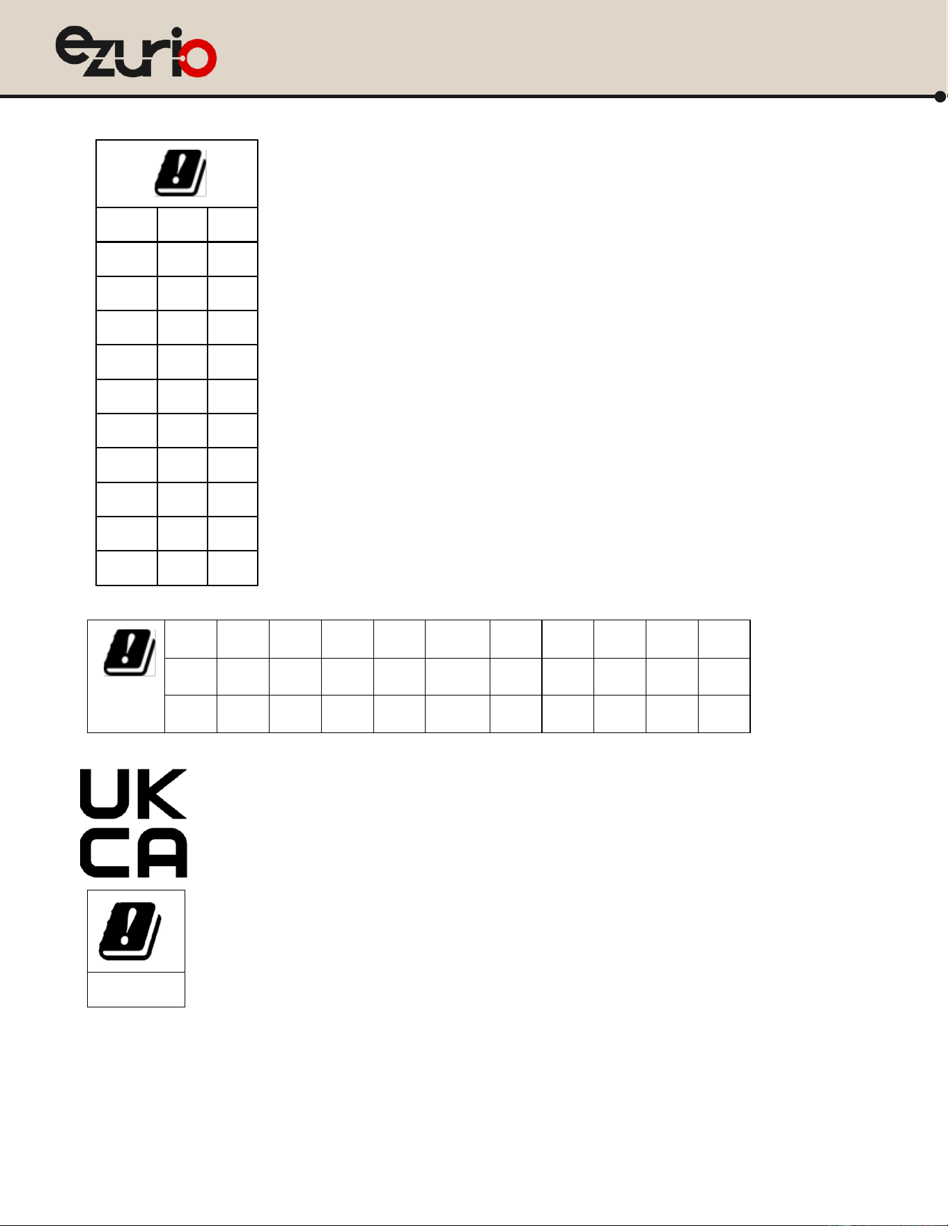
5150 ~ 5350 MHz is limited to indoor used in below countries.
https://www.ezurio.com/
34
© Copyright 2025 Ezurio
All Rights Reserved
Veda IF913
Datasheet
Option1
BE
BG
CZ
DK
DE
EE
IE
EL
ES
FR
HR
IT
CY
LV
LT
LU
HU
MT
NL
AT
PL
PT
RO
SI
SK
FI
SE
UK(NI)
LI
IS
NO
TR
CH
Option 2
BE
BG
CZ
DK
DE
EE
IE
EL
ES
FR
HR
IT
CY
LV
LT
LU
HU
MT
NL
AT
PL
PT
RO
SI
SK
FI
SE
UK(NI)
LI
IS
NO
TR
CH
UK

https://www.ezurio.com/
35
© Copyright 2025 Ezurio
All Rights Reserved
Veda IF913
Datasheet

https://www.ezurio.com/
36
© Copyright 2025 Ezurio
All Rights Reserved
Veda IF913
Datasheet
15 Additional Information
Please contact your local sales representative or our support team for further assistance:
Headquarters
Ezurio
50 S. Main St. Suite 1100
Akron, OH 44308 USA
Website
www.ezurio.com/
Technical Support
www.ezurio.com/resources/support
Sales Contact
www.ezurio.com/contact
Note: Information contained in this document is subject to change.
Ezurio’s products are subject to standard Terms & Conditions.
© Copyright 2025 Ezurio. All Rights Reserved. Patent pending. Any information furnished by Ezurio and its agents is believed to be accurate and reliable. All specifications are subject to change without notice. Responsibility for the use and application of Ezurio
materials or products rests with the end user since Ezurio and its agents cannot be aware of all potential uses. Ezurio makes no warranties as to non-infringement nor as to the fitness, merchantability, or sustainability of any Ezurio materials or products for any
specific or general uses. Ezurio or any of its affiliates or agents shall not be liable for incidental or consequential damages of any kind. All Ezurio products are sold pursuant to the Ezurio Terms and Conditions of Sale in effect from time to time, a copy of which
will be furnished upon request. Nothing herein provides a license under any Ezurio or any third-party intellectual property right.