
Technical Support and E-Warranty Certificate
www.vevor.com/support
MILL POWER TABLE FEED
MODEL:AL-260 AL-310
We continue to be committed to provide you tools with competitive price.
"Save Half", "Half Price" or any other similar expressions used by us only represents an
estimate of savings you might benefit from buying certain tools with us compared to the major
top brands and does not necessarily mean to cover all categories of tools offered by us. You
are kindly reminded to verify carefully when you are placing an order with us if you are
actually saving half in comparison with the top major brands.

- 1 -
MODEL:AL-260 AL-310
Have product questions? Need technical support? Please feel free to
contact us:
Technical Support and E-Warranty Certificate
www.vevor.com/support
NEED HELP? CONTACT US!
This is the original instruction, please read all manual instructions
carefully before operating. VEVOR reserves a clear interpretation of our
user manual. The appearance of the product shall be subject to the
product you received. Please forgive us that we won't inform you again if
there are any technology or software updates on our product.
MILL POWER TABLE FEED

- 2 -
BRIEF INTRODUCTION
Welcome to use this power feed.It will make your job convenient and make
you happy. Please read this manual carefully for your assembly and use of
this machine.
Suitable for any vertical turret milling machine feeders,including but not
limited to Bridgeport, precision Matthews,grizzly,enco,jet,sharp,Webb,GMC,
Clark,supermax,turn pro,vectrax,acra,Birmingham,accu,first and more,If
you mill with the same installation mode and 5/8"diameter shaft at the
end.As long as it is a Bridgeport type machine,it should be suitable.(it will
not be suitable for milling machines with different installation modes or lead
screws of different sizes,such as powermatic and some other strange
size machines,so please make sure your machine is the typical Bridgeport
type above)
SAFETY WARNING&CAUTIONS
1. Keep work area clean.Do not use this machine in damp,wet locations.Do
not use this machine in the presence of flammable gases or liquids.
2. The power source must coordinate with the power feed.
3. The SWITCH(034)should be in the "OFF"position when not in use or
before plugging.
4. Do not place any other thing on the machine.Avoid water or other liquids
to splash on the machine.
5. Do not use inappropriate attachments in an attempt to exceed the tool's
capacities
6. Maintain tools with care.

- 3 -
SPECIFICATIONS
Model
Spee
d
Maximum
Return Speed
Maximum
torque
Voltage
AL-260
0~200
277RPM
1385mm/min (external
screw lead 5mm)
450in-lb
110V(220V-240
V)50/60Hz
AL-310
0~200
277RPM
1385mm/min (external
screw lead 5mm)
450in-lb
110V(220V-240
V)50/60Hz
AL-450
0~200
277RPM
1385mm/min (external
screw lead 5mm)
450in-lb
110V(220V-240
V)50/60Hz
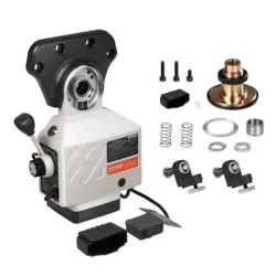
UNPACK
Project description
Quantity
Copper gear gasket
1
Install the retainer plate
1
Bearing inner race
1
Adjusting shim
15
Limit switch waterproof box
1
Limit switch spring
2
Limit block
2
Mounting screw
3
Copper gear
1

- 4 -
DRIVE UNIT INSTALLATION
Step 1: Remove the HAND
CRANK,DIAL and BEARING
FLANGE from the right side of
the table.
Step 2: Install the power feed
with the ADAPTER(027)to the
place of the BEARING
FLANGE.Assemble the
ADAPTER onto the table end
using four hex. screws.This
should be done together with
step 3 in order for the correct
position of the lead screw.
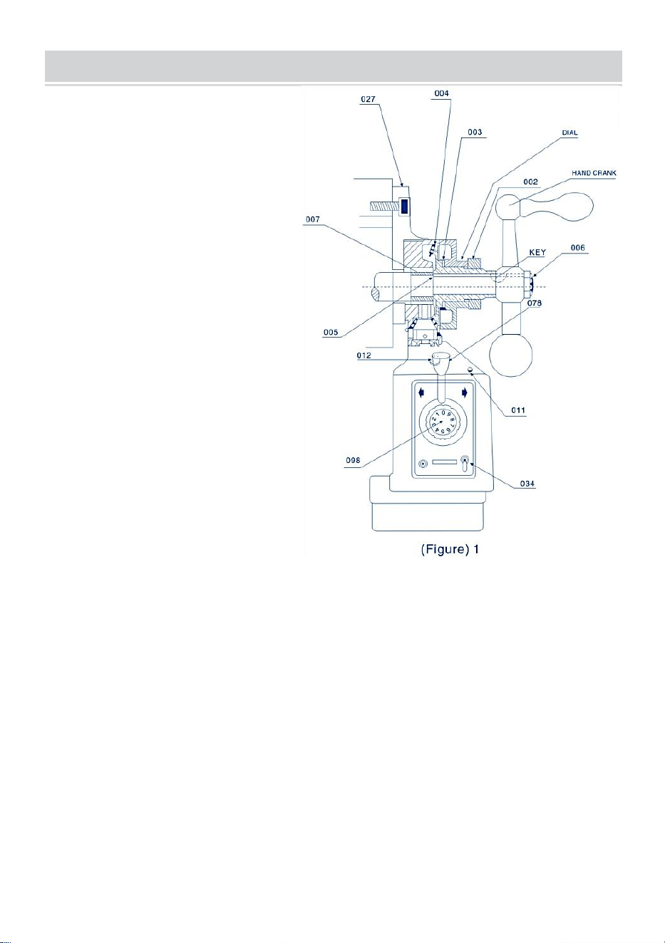
Step 3: Slide the INNER RING(007)over the lead screw of the table and
then into the hole of the needle bearing of the power feed.At last the
INNER RING should touch the lead screw's shoulder.Please reter to Figure
1(027,007)
Step 4: Insert the key in the keyway on the lead screw.
Step 5: Smear graphite base grease on the teeth of the BEVEL
GEAR(004).Place small amount of grease onto the inner face of the
BEVEL GEAR FLANGE.
Step 6: Install the BEVEL GEAR onto the lead screw with key and press it
up against the.DRIVE GEAR(061).
Notice: Generally,before installing BEVEL GEAR (004),you should insert
several SHIMS.(005)between INNER RING (007)and BEVEL

- 5 -
GEAR(004),so that you can get the smallest possible gap between the
gear assembly.The quantity of the SHIMS (005)you will use is determined
by your trial.
Please refer to Figure 1:005,004 etc.
Step 7: Install the appropriate DIAL on the BEVEL GEAR(CL004)referring
Figure1 and close to the Power feed flange(Do not touch each other!).Then
you may need several SHIMS(CL003)to meet the above requirement.
Step 8: Screw the NUT(002)into the BEVEL GEAR to avoid the DIAL loose.
Step 9: Reassemble the HAND CRANK removed in Step 1 onto the lead
screw.And then tighten BEVEL GEAR(004)or you can use the LOCKING
NUT(006)to tighten it.
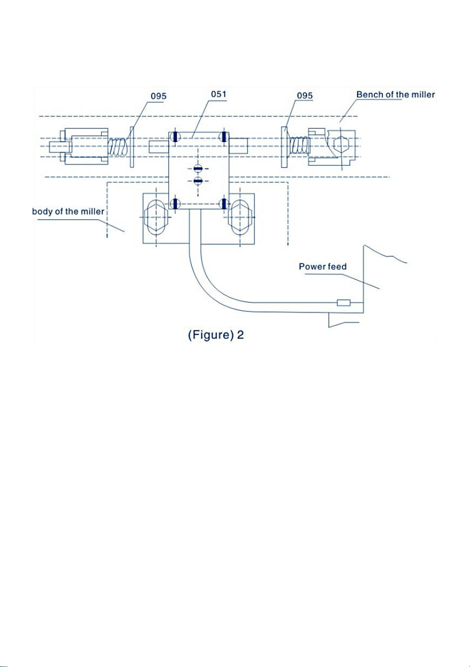
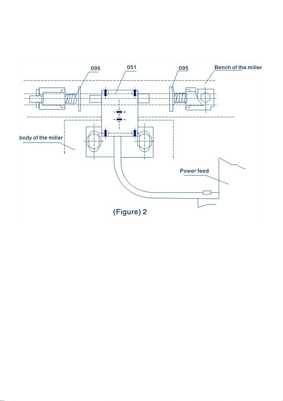
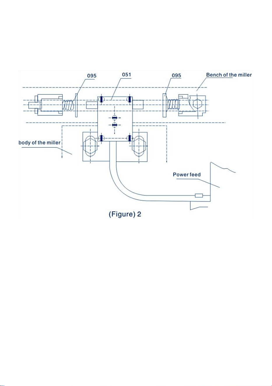
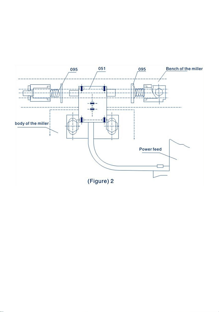
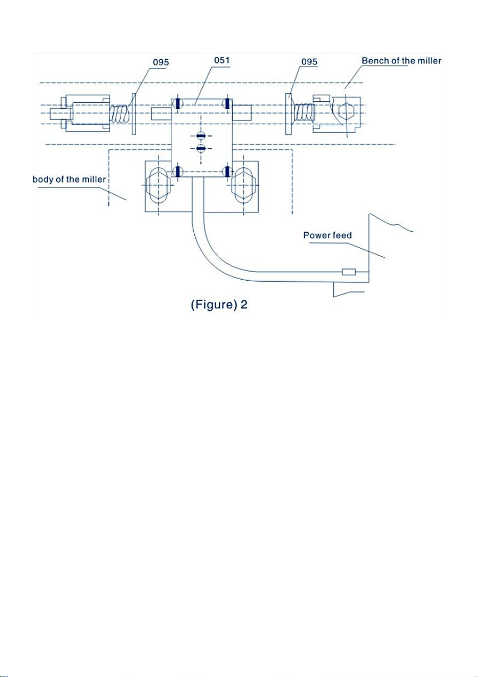
LIMIT ASSEMBLY INSTALL ATION
The power feed is equipped with LIMIT SWITCH ASSEMBLY(051)and
TRAVLE STOP ASSEMBLY(095).Its assembly is as follows (Please refer
to Figure2):
Step1: Remove the original travel stop assembly on the table and
assemble the TRAVEL STOP ASSEMBLY(B18)supplied instead.
Step2: Remove the original limit block and assemble the LIMIT SWITCH
ASSEMBLY (B05)supplied instead.
NOTICE
1、Be sure the two touching tods of the LIMIT SWITCH ASSEMBLY (051)
and the rod of the TRAVEL STOP ASSEMBLY(B18)should be on the same
axis.
2、The TRAVEL STOP ASSEMBLY(095)should be installed several
millimeters less than the stroke because of the inertia.
3、Protect the cord of the LIMIT SWITCH.Do not let it be winded by the
moving pieces or the table.

- 6 -
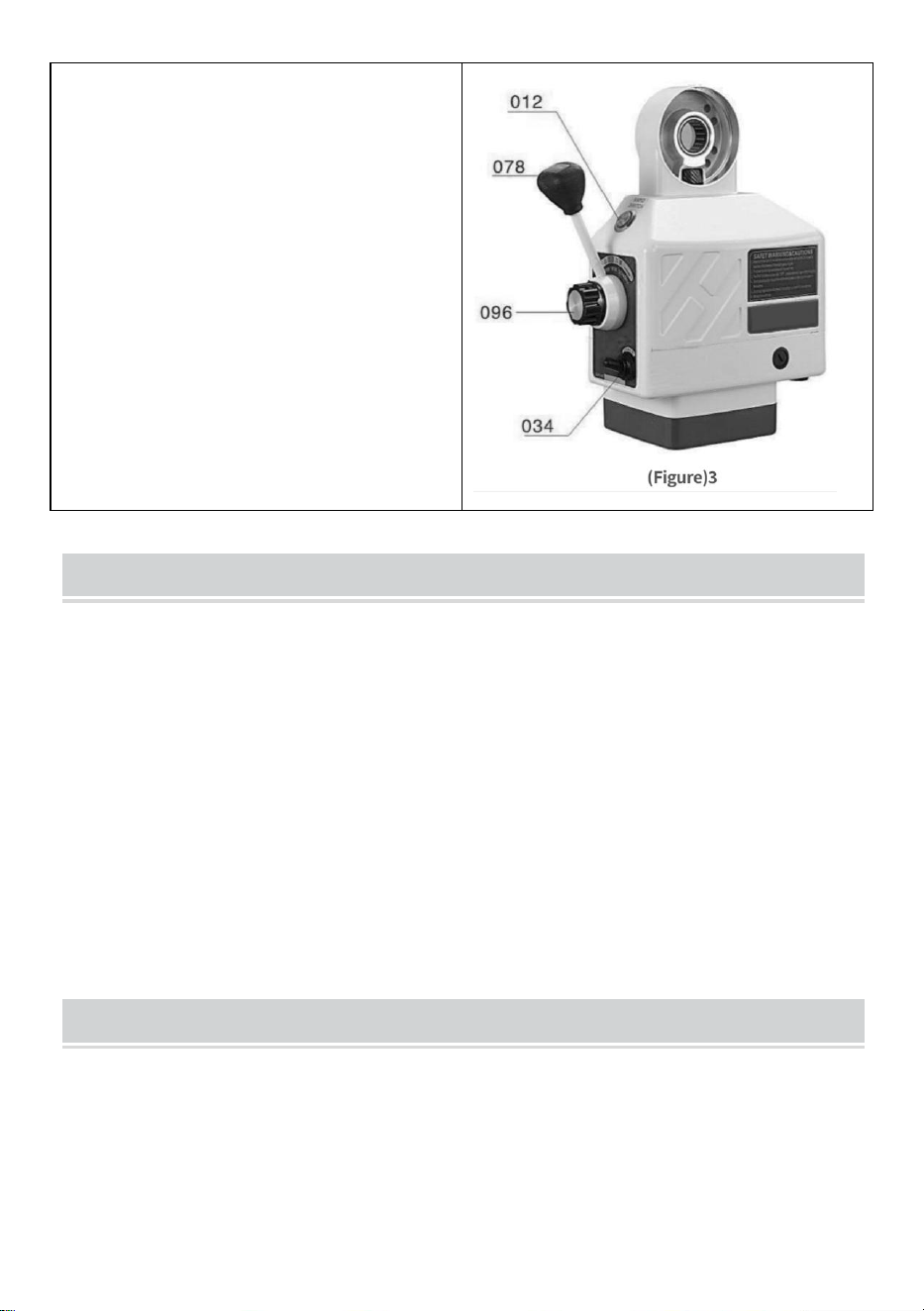
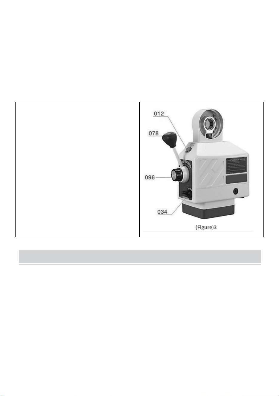
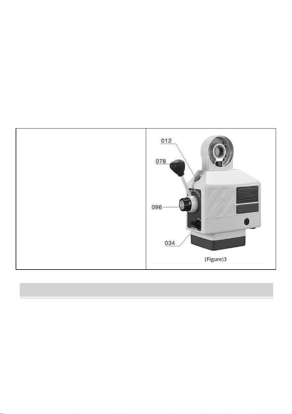
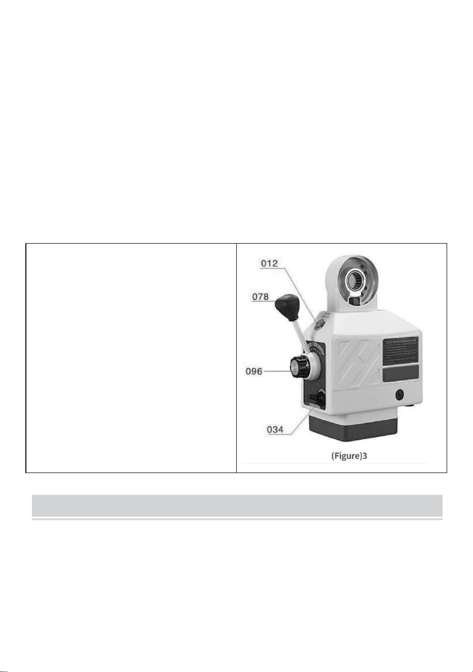
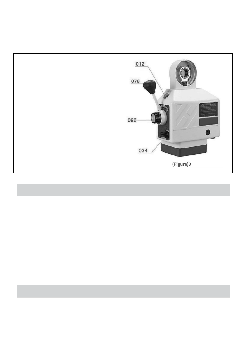
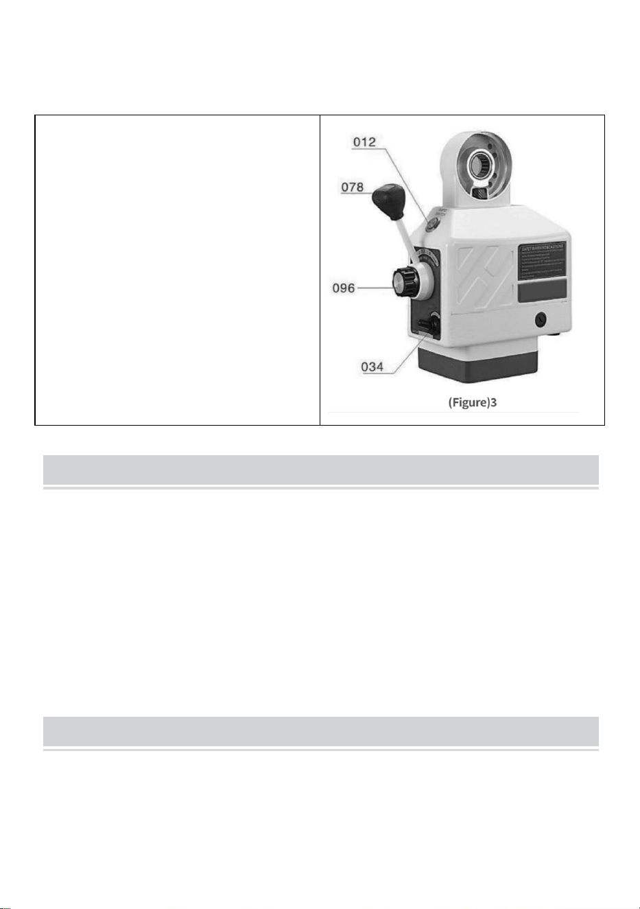
The operation of the power feed is as follows(Please refer to Figure3):
Step 1: Make sure the ON-OFF SWITCH(034)is in the“OFF”position and
the CONTROL HANDLE ASSEMBLY(078)is in the neutral (middle)position.
Step 2: Plug the power table feed cord into the stipulated outlet.
Step 3:Turn the ON-OFF SWITCH to the “ON”position,then LIGHT
TRANSMITTER(011)should light up.
Step 4:Turn the CONTROL HANDLE(078)away from the middle position to
one direction,then the table will move in the same direction.Turn the
SPEED CONTROL KNOB ASSY(096)clockwise,then the moving speed of
the table will be higher gradually.
Step 5: If you want to change the moving direction of the table,Please turn
the CONTROL HANDLE to the middle position until the power feed stops.
And then you can turn the CONTROL HANDLE in the direction you want.
(Make sure the power feed stops before you change the direction)
- 7 -
NOTICE
1. The speed is controlled by the
SPEED CONTROL KNOB
ASSY(B19).Position “o”represents"
stop" and “g”represents the highest
speed.
2. RAPID SWITCH BUTTON
(012)is for fast movement of the
table When it is pressed, then the
table will move at high speed.
PERIODIC MAINTENANCE
1、Clean the machine every 250 hours such as the rotor direction
change,carbon inside the machine and other dirt so that the insulation can
be ensured.
2、Lubrication.Insert lubrication oil into the gears and smear graphite base
grease on the teeth of the gears
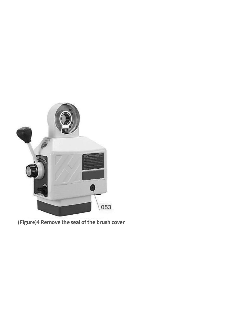
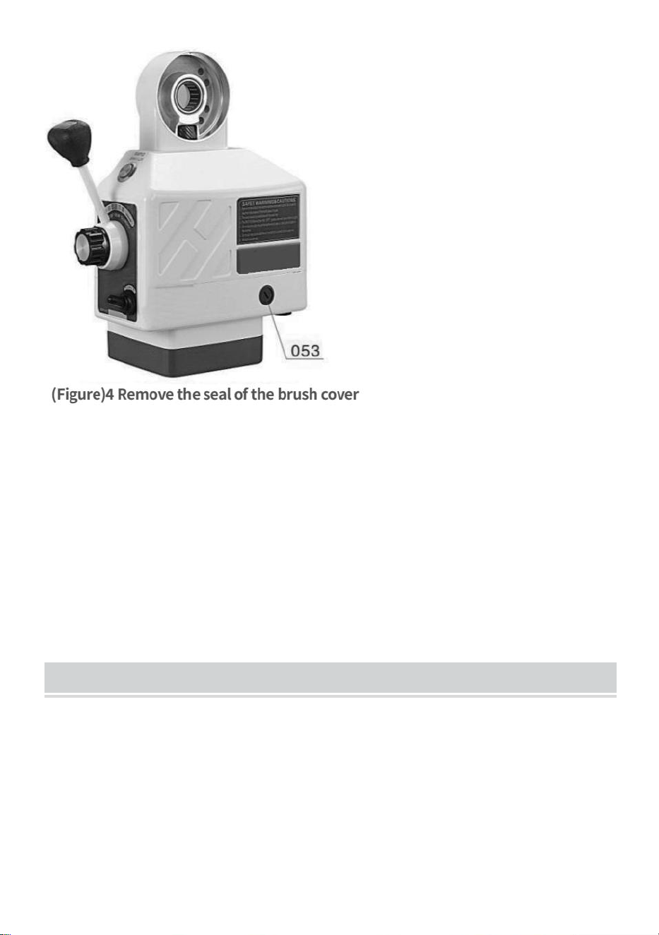
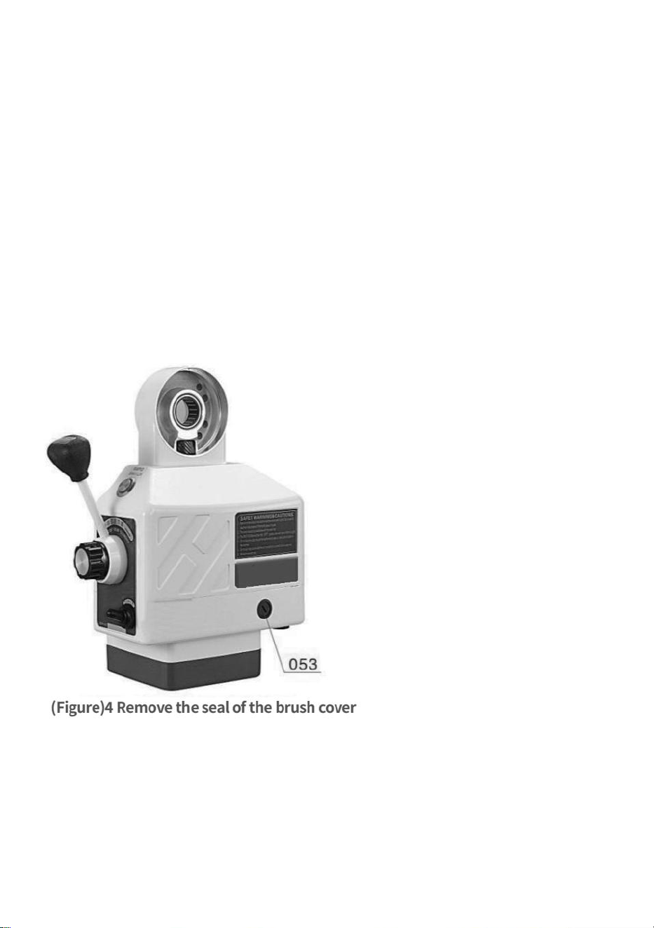
PEPLACEMNTOF BRUSH
Step 1: Remove the BRUSH CAP(053)(Please refer to Figure4).Then the
BRUSH(050)may spring out.Do not loosen the BRUSH.If the BRUSH does
not spring out,gently remove the BRUSH using the tip of your screwdriver.
Step 2: Examine the concave surface of the BRUSH.The surface should
- 8 -
be smooth and clean.If you find large scratch marks in the BRUSH or that
parts of the BRUSH have broken off or the length left of the BRUSH is only
6mm, replace the BRUSH immediately with an approved replacement
BRUSH. If the BRUSH is merely dirty,you can clean the BRUSH with a
pencil eraser.Clean off any bits Of eraser remaining on the BRUSH.
Step 3:There is a SPRING and BRASS PLUG attached to the
BRUSH.Turn the BRASS PLUG until the prongs are vertical and push the
BRUSH into the BRUSH HOLDER(052).Thread the BRUSH CAP into
the BRUSH HOL.DER and tighten.

- 9 -
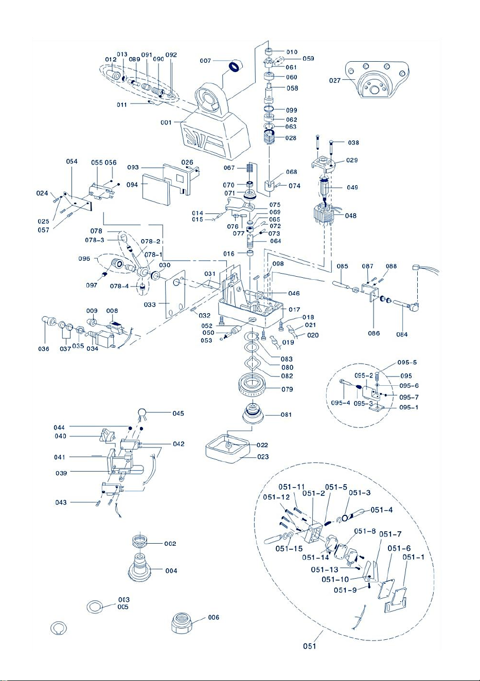
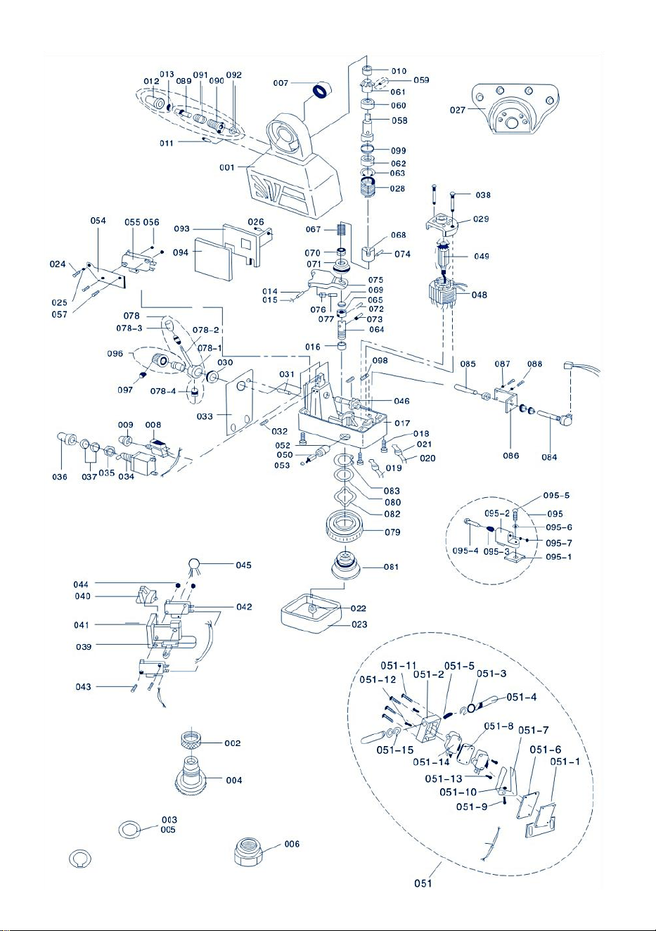
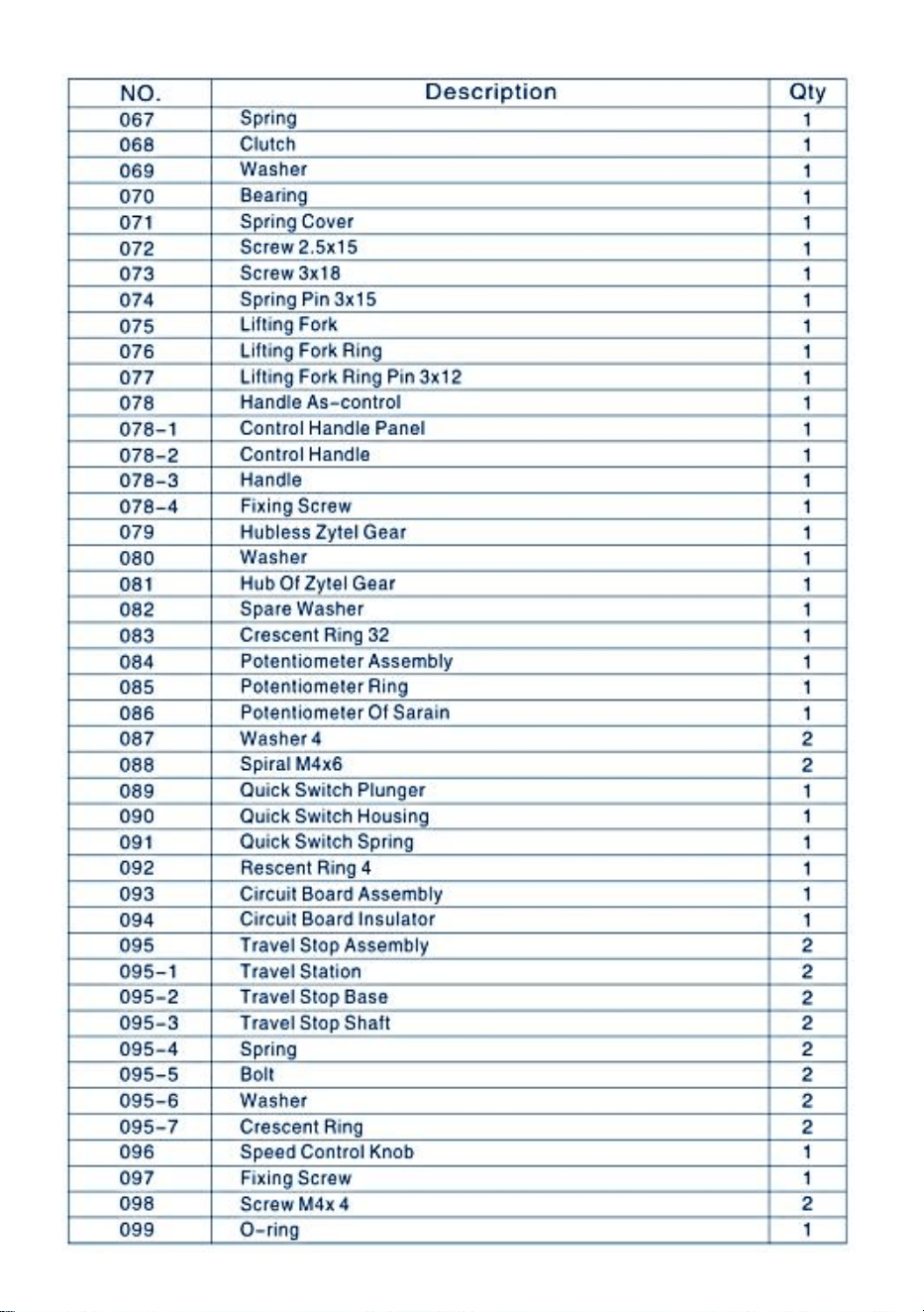
PARTS LIST

- 10 -

- 11 -

- 12 -

- 13 -
PARTS LIST
TROUBLE
REASONS AND SOLVENTS
The LIGHT
TRANS MITTER
does not glow.
1.There is something wrong with the power supply
or the wire connecting.
2.The CIRCUIT BREAKER is damaged.
3.ON-OFF SWITCH (034)is not in "ON"position or
damaged.
4.If the motor can move,then the
LIGHT TRANSMITTER is damaged
The motor does not
work when pushing
CONTROL HANDLE
(078) either left or
Right.
1.When pressing RAPID SPEED BUTTON(012),
the motor rotates:
①SPEED CONTROL KNOB is not in the"0"position
②POTENTIONMETER (084)can not work properly
③CIRCUIT BOARD(003)is damaged.
2.When pressing RAPID SPEED BUTTON(012),
the motor dose not rotate:
①The BRUSH and the ROTOR are not touching
properly or the BRUSH is used up
②The circuit inside is broken.
Current Leakage
1.There is short circuit across the BRUSH (050)
and the OUTER COVER(017)of the power feed or
there is short circuit in LIMIT SWITCH (051).
2.The carbon powder from the BRUSH results in
short circuit.

- 14 -
Sanven Technology Ltd.
Address: Suite 250, 9166 Anaheim Place, Rancho Cucamonga, CA
91730
Made In China


- 16 -
Technique Certificat d'assistance et de garantie électronique
www.vevor.com/support
ALIMENTATION DE LA TABLE
D'ALIMENTATION DU MOULIN
MODÈLE : AL-260 AL-310
We continue to be committed to provide you tools with competitive price.
"Save Half", "Half Price" or any other similar expressions used by us only represents an
estimate of savings you might benefit from buying certain tools with us compared to the major
top brands and does not necessarily mean to cover all categories of tools offered by us. You
are kindly reminded to verify carefully when you are placing an order with us if you are
actually saving half in comparison with the top major brands.

- 17 -

- 1 -
MODÈLE : AL-260 AL-310
Have product questions? Need technical support? Please feel free to
contact us:
Technical Support and E-Warranty Certificate
www.vevor.com/support
NEED HELP? CONTACT US!
This is the original instruction, please read all manual instructions
carefully before operating. VEVOR reserves a clear interpretation of our
user manual. The appearance of the product shall be subject to the
product you received. Please forgive us that we won't inform you again if
there are any technology or software updates on our product.
MILL POWER TABLE FEED

- 2 -
BRIEF INTRODUCTION
Bienvenue dans l'utilisation de cette alimentation électrique. Elle facilitera
votre travail et vous rendra heureux. Veuillez lire attentivement ce manuel
pour l'assemblage et l'utilisation de cette machine.
Convient à tous les alimentateurs de fraiseuses à tourelle verticale, y
compris, mais sans s'y limiter, Bridgeport, précision Matthews, grizzly,
enco, jet, sharp, Webb, GMC, Clark, supermax, turn pro, vectrax, acra,
Birmingham, accu, first et plus, si vous fraisez avec le même mode
d'installation et un arbre de 5/8" de diamètre à l'extrémité. Tant qu'il s'agit
d'une machine de type Bridgeport, elle devrait convenir. (elle ne
conviendra pas aux fraiseuses avec des modes d'installation différents ou
des vis mères de différentes tailles, telles que Powermatic et certaines
autres machines de taille étrange, veuillez donc vous assurer que votre
machine est du type Bridgeport typique ci-dessus)
SAFETY WARNING&CAUTIONS
1. Gardez la zone de travail propre. N'utilisez pas cette machine dans des
endroits humides ou mouillés. N'utilisez pas cette machine en présence de
gaz ou de liquides inflammables.
2. La source d’alimentation doit être coordonnée avec l’alimentation
électrique.
3. L'INTERRUPTEUR (034) doit être en position « OFF » lorsqu'il n'est pas
utilisé ou avant de le brancher.
4. Ne placez rien d'autre sur la machine. Évitez que de l'eau ou d'autres
liquides n'éclaboussent la machine.
5. N'utilisez pas d'accessoires inappropriés pour tenter de dépasser les
capacités de l'outil
6. Entretenez les outils avec soin.

- 3 -
SPECIFICATIONS
Modèle
Vitess
e
Maximum
Retour Vitesse
Maximum
couple
Tension
AL-260
0~ 20
0
2 77 tours/minute
1385 mm/min (pas de
vis externe 5 mm)
450 po-lb
110 V (220
V-240 V) 50/60
Hz
AL-310
0~ 20
0
2 77 tours/minute
1385 mm/min (pas de
vis externe 5 mm)
450 po-lb
110 V (220
V-240 V) 50/60
Hz
AL-450
0~ 20
0
2 77 tours/minute
1385 mm/min (pas de
vis externe 5 mm)
450 po-lb
110 V (220
V-240 V) 50/60
Hz
UNPACK
Description du projet
Quantité
Joint d'engrenage en cuivre
1
Installer la plaque de retenue
1
Bague intérieure de roulement
1
Cale de réglage
15
Boîtier étanche pour interrupteur de fin
de course
1
Ressort d'interrupteur de fin de course
2
Bloc limite
2
Vis de montage
3
Engrenage en cuivre
1

- 4 -
DRIVE UNIT INSTALLATION
Étape 1 : Retirez la
MANIVELLE, le CADRAN et la
BRIDE DE ROULEMENT de
droite côté de la table.
Étape 2 : Installez
l'alimentation avec
l'ADAPTATEUR (027) à la
place du ROULEMENT
BRIDE.Assemblez
l'ADAPTATEUR sur l'extrémité
de la table à l'aide de quatre
hexagones. vis. Cela doit être
fait en même temps que l'étape
3 pour que le bon position de la
vis mère.
Étape 3 : Faites glisser la BAGUE INTÉRIEURE (007) sur la vis mère de la
table, puis dans le trou du roulement à aiguilles de l'alimentation électrique.
Enfin, la BAGUE INTÉRIEURE doit toucher l'épaulement de la vis mère.
Veuillez vous référer à la figure 1 (027,007)
Étape 4 : Insérez la clé dans la rainure de la vis mère.
Étape 5 : Appliquez de la graisse à base de graphite sur les dents de
l'ENGRENAGE CONIQUE (004). Placez une petite quantité de graisse sur
la face intérieure de la BRIDE DE L'ENGRENAGE CONIQUE.
Étape 6 : Installez l'ENGRENAGE CONIQUE sur la vis mère avec la clé et
appuyez-le contre l'ENGRENAGE D'ENTRAÎNEMENT (061).

- 5 -
Remarque : En général, avant d'installer l'ENGRENAGE CONIQUE (004),
vous devez insérer plusieurs CALES (005) entre la BAGUE INTÉRIEURE
(007) et l'ENGRENAGE CONIQUE (004), afin d'obtenir le plus petit espace
possible entre l'ensemble d'engrenages. La quantité de CALES (005) que
vous utiliserez est déterminée par votre essai.
Veuillez vous référer à la figure 1:005,004 etc.
Étape 7 : Installez le CADRAN approprié sur l'ENGRENAGE CONIQUE
(CL004) en vous référant à la Figure 1 et à proximité de la bride
d'alimentation (ne vous touchez pas !). Vous aurez alors peut-être besoin
de plusieurs CALES (CL003) pour répondre à l'exigence ci-dessus.
Étape 8 : Vissez l'ÉCROU (002) dans l'ENGRENAGE CONIQUE pour
éviter que le CADRAN ne se desserre.
Étape 9 : Remontez la MANIVELLE retirée à l'étape 1 sur la vis mère. Puis
serrez l'ENGRENAGE CONIQUE (004) ou vous pouvez utiliser l'ÉCROU
DE BLOCAGE (006) pour le serrer.
LIMIT ASSEMBLY INSTALL ATION
L'alimentation est équipée d'un ENSEMBLE INTERRUPTEUR DE FIN DE
COURSE (051) et d'un ENSEMBLE ARRÊT DE DÉPLACEMENT (095).
Son assemblage est le suivant (veuillez vous référer à la Figure 2) :
Étape 1 : Retirez l'ensemble de butée de course d'origine sur la table et
assemblez-le le VOYAGE STOP ASSEMBLY(B18) fourni à la place.
Étape 2 : Retirez le bloc de limite d'origine et assemblez-le l'ENSEMBLE
INTERRUPTEUR DE FIN DE COURSE (B05) fourni à la place.
AVIS
1、Assurez-vous que les deux boutons de contact de l'INTERRUPTEUR
DE FIN DE COURSE ASSEMBLÉE (051) et la tige de l'ENSEMBLE DE
BUTÉE DE DÉPLACEMENT (B18) doit être sur le même axe.
2、Le VOYAGE L'ASSEMBLAGE D'ARRÊT (095) doit être installé à
- 6 -
quelques millimètres de moins que l'AVC en raison de l'inertie.
3. Protégez le cordon de l'INTERRUPTEUR DE FIN DE COURSE. Ne le
laissez pas s'enrouler par le mouvement. des morceaux ou la table.
Le fonctionnement de l'alimentation électrique est le suivant (veuillez vous
référer à la figure 3) :
Étape 1 : Assurez-vous que l'INTERRUPTEUR MARCHE-ARRÊT (034)
est en position « ARRÊT » et que l'ENSEMBLE DE POIGNÉE DE
COMMANDE (078) est en position neutre (milieu).
Étape 2 : Branchez le cordon d’alimentation de la table d’alimentation dans
la prise prévue à cet effet.
Étape 3 : Tournez l'INTERRUPTEUR MARCHE-ARRÊT sur la position «
ON » , puis allumez
L'ÉMETTEUR (011) doit s'allumer.
Étape 4 : Tournez le bouton CONTROL POIGNÉE (078) loin de la position
médiane dans une direction, puis la table se déplacera dans la même
direction. Tournez la VITESSE BOUTON DE COMMANDE (096) dans le
sens des aiguilles d'une montre, puis la vitesse de déplacement de la table
sera progressivement plus élevé.

- 7 -
Étape 5 : Si vous souhaitez modifier le sens de déplacement de la table,
veuillez tourner le POIGNÉE DE COMMANDE en position médiane jusqu'à
ce que l'alimentation électrique s'arrête. Et ensuite vous pouvez tourner la
POIGNÉE DE COMMANDE dans la direction tu veux.
(Assurez-vous que l'alimentation électrique s'arrête avant tu changes la
direction)
AVIS
1. La vitesse est contrôlée par le
SPEED ENSEMBLE DE BOUTON
DE COMMANDE (B19). La position
« o » représente « arrêt » et « g »
représente la vitesse la plus élevée.
3. Le bouton de commutation
rapide (012) est destiné à
mouvement rapide de la table
Lorsqu'elle est pressée, alors la
table se déplacera à grande vitesse.
PERIODIC MAINTENANCE
1. Nettoyez la machine toutes les 250 heures, comme le changement de
direction du rotor, le carbone à l'intérieur de la machine et d'autres saletés
afin que l'isolation puisse être assurée.
2. Lubrification. Insérez de l'huile de lubrification dans les engrenages et
étalez de la graisse à base de graphite sur les dents des engrenages

- 8 -
PEPLACEMNTOF BRUSH
Étape 1 : Retirez le CAPUCHON DE LA BROSSE (053) (Veuillez vous
référer à la Figure 4). La BROSSE (050) peut alors sortir. Ne desserrez
pas la BROSSE. Si la BROSSE ne sort pas, retirez-la délicatement à l'aide
de la pointe de votre tournevis.
Étape 2 : Examinez la surface concave de la BROSSE. La surface doit être
lisse et propre. Si vous trouvez une grande rayure des marques dans le
PINCEAU ou que des parties de la BROSSE est cassée ou la la longueur
restante du PINCEAU est seulement de 6 mm, remplacer la BROSSE
immédiatement avec une BROSSE de remplacement approuvée. Si la
BROSSE est simplement sale, vous pouvez nettoyer le PINCEAU avec un
crayon gomme. Nettoyez tous les morceaux de gomme restant sur le
PINCEAU.
Étape 3 : Il y a un RESSORT et un BOUCHON EN LAITON ci-joint au
BROSSE.Tournez la BOUCHON EN LAITON jusqu'à ce que les broches
soient verticalement et poussez la BROSSE dans le PORTE-BROSSE
(052). Enfilez le CAPUCHON DE BROSSE dans le PORTE-BROSSE et
serrer.
- 9 -
PARTS LIST

- 10 -

- 11 -
- 12 -

- 13 -

- 14 -
PARTS LIST
INQUIÉTER
RAISONS ET SOLVANTS
Le
TRANSMETTEUR
DE LUMIÈRE ne
fonctionne pas
briller.
1. Il y a un problème avec l'alimentation électrique
ou le fil de connexion.
2. Le DISJONCTEUR est endommagé.
3. L'INTERRUPTEUR MARCHE-ARRÊT (034)
n'est pas en position « ON » ou
endommagé.
4. Si le moteur peut bouger, alors le
L'ÉMETTEUR DE LUMIÈRE est endommagé
Le moteur ne
fonctionne pas
travailler en
poussant
CONTRÔLE
POIGNÉE (078) soit
à gauche ou Droite .
1. Lorsque vous appuyez sur le bouton VITESSE
RAPIDE (012),
le moteur tourne:
①Le bouton de contrôle de la vitesse n'est pas en
position « 0 » ②Le potentiomètre (084) ne peut pas
fonctionner correctement
③Le CIRCUIT IMPRIMÉ (003) est endommagé.
2. Lorsque vous appuyez sur RAPID SPEED
BOUTON (012), le le moteur ne tourne pas :
①La BROSSE et le ROTOR ne se touchent pas
correctement ou la BROSSE est épuisée
②Le circuit à l’intérieur est rompu.
Courant de fuite
1. Il y a un court-circuit sur la BROSSE (050) et le
COUVERCLE EXTÉRIEUR (017) de l'alimentation
ou
il y a un court-circuit dans l'INTERRUPTEUR DE
FIN DE COURSE (051). 2. La poudre de carbone
de la BROSSE entraîne
court-circuit.

- 15 -
Sanven Technologie Ltée.
Adresse : Suite 250, 9166 Anaheim Place, Rancho Cucamonga, CA
91730
Fabriqué en Chine


- 17 -
Technisch Support und E-Garantie-Zertifikat
www.vevor.com/support
FRÄSTISCHVORSCHUB
MODELL: AL-260 AL-310
We continue to be committed to provide you tools with competitive price.
"Save Half", "Half Price" or any other similar expressions used by us only represents an
estimate of savings you might benefit from buying certain tools with us compared to the major
top brands and does not necessarily mean to cover all categories of tools offered by us. You
are kindly reminded to verify carefully when you are placing an order with us if you are
actually saving half in comparison with the top major brands.

- 1 -
MODELL: AL-260 AL-310
Have product questions? Need technical support? Please feel free to
contact us:
Technical Support and E-Warranty Certificate
www.vevor.com/support
NEED HELP? CONTACT US!
This is the original instruction, please read all manual instructions
carefully before operating. VEVOR reserves a clear interpretation of our
user manual. The appearance of the product shall be subject to the
product you received. Please forgive us that we won't inform you again if
there are any technology or software updates on our product.
MILL POWER TABLE FEED

- 2 -
BRIEF INTRODUCTION
Willkommen bei der Verwendung dieses Power Feeds. Er wird Ihre Arbeit
bequemer und angenehmer machen. Bitte lesen Sie dieses Handbuch
sorgfältig durch, um die Montage und Verwendung dieser Maschine zu
erleichtern.
Geeignet für alle vertikalen Revolverfräsmaschinen-Feeder, einschließlich,
aber nicht beschränkt auf Bridgeport, Precision Matthews, Grizzly, Enco,
Jet, Sharp, Webb, GMC, Clark, Supermax, Turn Pro, Vectrax, Acra,
Birmingham, Accu, First und mehr. Wenn Sie mit dem gleichen
Installationsmodus und einer Welle mit 5/8 Zoll Durchmesser am Ende
fräsen, sollte es geeignet sein, solange es sich um eine Maschine vom Typ
Bridgeport handelt. (Es ist nicht geeignet für Fräsmaschinen mit anderen
Installationsmodi oder Leitspindeln unterschiedlicher Größe, wie z. B.
Powermatic und einige andere Maschinen mit ungewöhnlichen Größen.
Stellen Sie daher sicher, dass Ihre Maschine vom oben genannten
typischen Bridgeport-Typ ist.)
SAFETY WARNING&CAUTIONS
1. Halten Sie den Arbeitsbereich sauber. Verwenden Sie diese Maschine
nicht an feuchten oder nassen Orten. Verwenden Sie diese Maschine nicht
in der Nähe von brennbaren Gasen oder Flüssigkeiten.
2. Die Stromquelle muss mit der Stromzufuhr harmonieren.
3. Der SCHALTER (034) sollte sich bei Nichtgebrauch oder vor dem
Einstecken in der Position „AUS“ befinden.
4. Stellen Sie keine anderen Gegenstände auf die Maschine. Vermeiden
Sie, dass Wasser oder andere Flüssigkeiten auf die Maschine spritzen.
5. Verwenden Sie keine ungeeigneten Aufsätze, um die Leistungsfähigkeit
des Werkzeugs zu überschreiten
6. Pflegen Sie die Werkzeuge sorgfältig.

- 3 -
SPECIFICATIONS
Modell
Gesc
hwindi
gkeit
Maximal
Zurückkehren
Geschwindigkeit
Maximal
Drehmome
nt
Stromspannung
AL-260
0~ 20
0
2 77 U/min
1385 mm/min
(Außengewindesteigun
g 5 mm)
450
Zoll-Pfund
110 V (220 V –
240 V), 50/60
Hz
AL-310
0~ 20
0
2 77 U/min
1385 mm/min
(Außengewindesteigun
g 5 mm)
450
Zoll-Pfund
110 V (220 V –
240 V), 50/60
Hz
AL-450
0~ 20
0
2 77 U/min
1385 mm/min (äußere
Gewindesteigung 5
mm)
450
Zoll-Pfund
110 V (220 V –
240 V), 50/60
Hz
UNPACK
Projektbeschreibung
Menge
Kupfer-Getriebedichtung
1
Installieren Sie die Halteplatte
1
Lagerinnenring
1
Einstellscheibe
15
Wasserdichte Endschalterbox
1
Endschalterfeder
2
Begrenzungsblock
2
Befestigungsschraube
3
Kupfergetriebe
1
- 4 -
DRIVE UNIT INSTALLATION
Schritt 1: Entfernen Sie die
HANDKURBEL, das
ZIFFERBLATT und den
LAGERFLANSCH von der
rechten Seite des Tisches.
Schritt 2: Installieren Sie die
Stromversorgung mit dem
ADAPTER (027) an der Stelle
des LAGERS FLANSCH.
Montieren Sie den ADAPTER
mit vier Sechskantschrauben
am Tischende. Dies sollte
zusammen mit Schritt 3
durchgeführt werden, um die
richtige Position der
Leitspindel.
Schritt 3: Schieben Sie den INNENRING (007) über die Leitspindel des
Tisches und dann in die Öffnung des Nadellagers der Stromzufuhr.
Schließlich sollte der INNENRING die Schulter der Leitspindel berühren.
Siehe Abbildung 1 (027,007).
Schritt 4: Stecken Sie den Schlüssel in die Keilnut der Leitspindel.
Schritt 5: Tragen Sie Graphitfett auf die Zähne des KEGELRADS (004) auf.
Geben Sie eine kleine Menge Fett auf die Innenseite des
KEGELRADFLANSCHS.
Schritt 6: Montieren Sie das KEGELRAD mit dem Schlüssel auf der

- 5 -
Leitspindel und drücken Sie es gegen das ANTRIEBSRAD (061).
Hinweis: Generell sollten Sie vor dem Einbau des KEGELRADS (004)
mehrere UNTERLEGSCHEIBEN (005) zwischen INNENRING (007) und
KEGELRAD (004) einfügen, um den kleinstmöglichen Abstand zwischen
den Zahnrädern zu erhalten. Die Anzahl der zu verwendenden
UNTERLEGSCHEIBEN (005) wird durch Ihren Versuch bestimmt.
Siehe Abbildung 1:005,004 usw.
Schritt 7: Installieren Sie das entsprechende ZIFFERBLATT am
KEGELRAD (CL004), siehe Abbildung 1, und in der Nähe des
Kraftzufuhrflansches (berühren Sie sich nicht gegenseitig!). Dann
benötigen Sie möglicherweise mehrere UNTERLEGSCHEIBEN (CL003),
um die oben genannte Anforderung zu erfüllen.
Schritt 8: Schrauben Sie die MUTTER (002) in das KEGELRAD, um zu
verhindern, dass sich das ZIFFERBLATT löst.
Schritt 9: Montieren Sie die in Schritt 1 entfernte HANDKURBEL wieder an
der Leitspindel. Ziehen Sie dann das KEGELRAD (004) fest, oder
verwenden Sie die SICHERUNGSMUTTER (006), um es festzuziehen.
LIMIT ASSEMBLY INSTALL ATION
Die Stromzufuhr ist mit einer ENDSCHALTERBAUGRUPPE (051) und
einer FAHRSTOPP-BAUGRUPPE (095) ausgestattet. Die Montage erfolgt
wie folgt (siehe Abbildung 2):
Schritt 1: Die originale Hubbegrenzungsbaugruppe vom Tisch entfernen
und montieren die REISE Stattdessen wird die STOP-BAUGRUPPE (B18)
mitgeliefert.
Schritt 2: Den Original-Endanschlag demontieren und montieren
stattdessen die mitgelieferte ENDSCHALTERBAUGRUPPE (B05).
BEACHTEN
1. Stellen Sie sicher, dass die beiden Berührungspunkte des
ENDSCHALTERS MONTAGE (051) und die Stange der
Wegbegrenzungsbaugruppe (B18) sollten auf der gleichen Achse liegen.
- 6 -
2. Die REISE STOP ASSEMBLY(095)sollte einige Millimeter weniger
installiert werden als der Hub aufgrund der Trägheit.
3. Schützen Sie das Kabel des ENDSCHALTERS. Lassen Sie es nicht
durch die sich bewegende Stücke oder den Tisch.
Die Funktionsweise der Stromzufuhr ist wie folgt (siehe Abbildung 3):
Schritt 1: Stellen Sie sicher, dass sich der EIN-/AUS-SCHALTER (034) in
der Position „AUS“ befindet und sich die STEUERGRIFFBAUGRUPPE
(078) in der neutralen (mittleren) Position befindet .
Schritt 2: Stecken Sie das Netzkabel des Tisches in die vorgesehene
Steckdose.
Schritt 3: Schalten Sie den EIN-/AUS-SCHALTER auf die Position
„ON“ und schalten Sie dann das LICHT ein.
SENDER (011) sollte aufleuchten.
Schritt 4: Drehen Sie den CONTROL GRIFF(078) von der Mittelstellung in
eine Richtung weg, dann bewegt sich der Tisch in die gleiche
Richtung.Drehen Sie den SPEED CONTROL KNOPF ASSY(096)im
Uhrzeigersinn, dann die Bewegungsgeschwindigkeit des Tisches wird
schrittweise höher sein.
- 7 -
Schritt 5: Wenn Sie die Bewegungsrichtung des Tisches ändern möchten,
drehen Sie bitte den Steuergriff in die mittlere Position bis die Stromzufuhr
stoppt. Und dann können Sie drehen der STEUERGRIFF in die Richtung
Sie möchten.
(Stellen Sie sicher, dass die Stromzufuhr stoppt, bevor du änderst die
Richtung)
BEACHTEN
1. Die Geschwindigkeit wird durch
den SPEED- BEDIENKNOPF
BAUGRUPPE (B19).Position
„o“ steht für „Stopp“ und „g“ steht für
die höchste Geschwindigkeit.
4. SCHNELLSCHALTER (012) ist
für schnelle Bewegung der Tabelle
Wenn es gedrückt wird, dann
bewegt sich der Tisch mit hoher
Geschwindigkeit.
PERIODIC MAINTENANCE
1. Reinigen Sie die Maschine alle 250 Stunden, beispielsweise beim
Richtungswechsel des Rotors, auf Kohlenstoff im Inneren der Maschine
und auf anderen Schmutz, damit die Isolierung gewährleistet bleiben kann.
2. Schmierung. Schmieröl in die Zahnräder einfüllen und Graphitfett auf die
Zähne der Zahnräder auftragen.

- 8 -
PEPLACEMNTOF BRUSH
Schritt 1: Entfernen Sie die BÜRSTENKAPPE (053) (siehe Abbildung 4).
Dann kann die BÜRSTE (050) herausspringen. Lösen Sie die BÜRSTE
nicht. Wenn die BÜRSTE nicht herausspringt, entfernen Sie sie vorsichtig
mit der Spitze Ihres Schraubendrehers.
Schritt 2: Untersuchen Sie die konkave Oberfläche der BÜRSTE. Die
Oberfläche sollte glatt und sauber sein. Wenn Sie große Kratzer finden
Flecken in der BÜRSTE oder dass Teile der die BÜRSTE ist abgebrochen
oder die Die verbleibende Länge der Bürste beträgt nur 6 mm. Ersetzen
Sie die BÜRSTE sofort mit eine zugelassene ErsatzBÜRSTE. Wenn die
BÜRSTE nur schmutzig ist, können Sie Reinigen Sie den Pinsel mit einem
Bleistift Radiergummi.Reinigen Sie alle Radiergummireste verbleibende
Reste auf der BÜRSTE.
Schritt 3: Es gibt eine FEDER und einen MESSINGSTECKER beigefügt
zur BÜRSTE.Drehen Sie die MESSINGSTECKER, bis die Stifte senkrecht
stellen und die BÜRSTE in die Bürstenhalter (052). PINSELKAPPE in den
PINSELHALTER und festziehen.

- 9 -
PARTS LIST

- 10 -

- 11 -

- 12 -

- 13 -

- 14 -
PARTS LIST
PROBLEM
GRÜNDE UND LÖSUNGSMITTEL
Der
LICHTÜBERTRAGER
glühen.
1.Es liegt ein Problem mit der Stromversorgung
vor oder die Kabelverbindung.
2.Der Leistungsschalter ist beschädigt.
3.Der EIN-AUS-SCHALTER (034) ist nicht in der
Position „ON“ oder
beschädigt.
4.Wenn der Motor sich bewegen kann, dann die
LICHTSENDER ist beschädigt
Der Motor funktioniert
nicht
Arbeit beim Schieben
KONTROLLE
HANDHABEN (078)
entweder links oder
Rechts .
1.Wenn Sie die SCHNELLE
GESCHWINDIGKEITSTASTE (012) drücken,
der Motor dreht sich:
①Der Drehzahlregler ist nicht in der Position „0“.
②Das Potentiometer (084) funktioniert nicht
richtig.
③Leiterplatte (003) ist beschädigt.
2.Wenn Sie RAPID SPEED drücken TASTE(012),
Die Motor dreht nicht:
①Die BÜRSTE und der ROTOR berühren sich
nicht
richtig oder die BÜRSTE ist verbraucht
②Der Stromkreis im Inneren ist unterbrochen.
Aktueller Leckstrom
1.Es liegt ein Kurzschluss über der BÜRSTE vor
(050) Und die AUSSENABDECKUNG(017) der
Stromzuführung oder
es liegt ein Kurzschluss im ENDSCHALTER (051)
vor. 2.Der Kohlenstoffstaub von der BÜRSTE
führt zu
Kurzschluss.

- 15 -
Sanven Technology Ltd.
Adresse: Suite 250, 9166 Anaheim Place, Rancho Cucamonga, CA
91730
In China hergestellt


- 17 -
Tecnico Supporto e certificato di garanzia elettronica
www.vevor.com/support
ALIMENTAZIONE TAVOLA MULINO
MODELLO:AL-260 AL-310
We continue to be committed to provide you tools with competitive price.
"Save Half", "Half Price" or any other similar expressions used by us only represents an
estimate of savings you might benefit from buying certain tools with us compared to the major
top brands and does not necessarily mean to cover all categories of tools offered by us. You
are kindly reminded to verify carefully when you are placing an order with us if you are
actually saving half in comparison with the top major brands.

- 1 -
MODELLO:AL-260 AL-310
Have product questions? Need technical support? Please feel free to
contact us:
Technical Support and E-Warranty Certificate
www.vevor.com/support
NEED HELP? CONTACT US!
This is the original instruction, please read all manual instructions
carefully before operating. VEVOR reserves a clear interpretation of our
user manual. The appearance of the product shall be subject to the
product you received. Please forgive us that we won't inform you again if
there are any technology or software updates on our product.
MILL POWER TABLE FEED

- 2 -
BRIEF INTRODUCTION
Benvenuti a usare questo alimentatore. Renderà il vostro lavoro più
comodo e vi renderà felici. Si prega di leggere attentamente questo
manuale per il montaggio e l'uso di questa macchina.
Adatto a qualsiasi alimentatore per fresatrice a torretta verticale, inclusi ma
non limitati a Bridgeport, Precisione Matthews, Grizzly, Enco, Jet, Sharp,
Webb, GMC, Clark, Supermax, Turn Pro, Vectrax, Acra, Birmingham, Accu,
First e altro ancora, se si esegue la fresatura con la stessa modalità di
installazione e un albero da 5/8" di diametro all'estremità. Finché si tratta di
una macchina di tipo Bridgeport, dovrebbe essere adatta. (Non sarà adatta
per fresatrici con diverse modalità di installazione o viti madri di dimensioni
diverse, come Powermatic e alcune altre macchine di dimensioni strane,
quindi assicurati che la tua macchina sia del tipico tipo Bridgeport sopra
indicato)
SAFETY WARNING&CAUTIONS
1. Mantenere pulita l'area di lavoro. Non utilizzare la macchina in luoghi
umidi o bagnati. Non utilizzare la macchina in presenza di gas o liquidi
infiammabili.
2. La fonte di alimentazione deve essere coordinata con l'alimentazione.
3. L'INTERRUTTORE (034) deve essere in posizione "OFF" quando non è
in uso o prima di collegare il dispositivo.
4. Non appoggiare altri oggetti sulla macchina. Evitare che acqua o altri
liquidi schizzino sulla macchina.
5. Non utilizzare accessori inappropriati nel tentativo di superare le
capacità dell'utensile
6. Mantenere gli utensili con cura.

- 3 -
SPECIFICATIONS
Modello
Veloci
tà
Massimo
Ritorno Velocità
Massimo
coppia
Voltaggio
AL-260
Da 0
a 20 0
2 77 giri al minuto
1385mm/min (passo
vite esterno 5mm)
450
libbre-polli
ci
110 V (220
V-240 V) 50/60
Hz
AL-310
Da 0
a 20 0
2 77 giri al minuto
1385mm/min (passo
vite esterno 5mm)
450
libbre-polli
ci
110 V (220
V-240 V) 50/60
Hz
AL-450
Da 0
a 20 0
2 77 giri al minuto
1385mm/min (passo
vite esterno 5mm)
450
libbre-polli
ci
110 V (220
V-240 V) 50/60
Hz
UNPACK
Descrizione del progetto
Quantità
Guarnizione per ingranaggi in rame
1
Installare la piastra di fissaggio
1
Pista interna del cuscinetto
1
Spessore di regolazione
15
Scatola impermeabile con finecorsa
1
Molla finecorsa
2
Blocco limite
2
Vite di montaggio
3
Ingranaggio in rame
1

- 4 -
DRIVE UNIT INSTALLATION
Fase 1: Rimuovere la
MANOVELLA, il QUADRANTE
e la FLANGIA DEL
CUSCINETTO dal lato destro
lato del tavolo.
Fase 2: Installare l'alimentatore
con l'ADATTATORE (027) al
posto del CUSCINETTO
FLANGIA. Montare
l'ADATTATORE sull'estremità
del tavolo utilizzando quattro
viti esagonali. viti. Questo
dovrebbe essere fatto insieme
al passaggio 3 per il corretto
posizione della vite di
comando.
Fase 3: Far scorrere l'ANELLO INTERNO (007) sulla vite di comando del
tavolo e poi nel foro del cuscinetto ad aghi dell'alimentatore. Alla fine
l'ANELLO INTERNO dovrebbe toccare la spalla della vite di comando.
Fare riferimento alla Figura 1 (027,007)
Fase 4: Inserire la chiave nella sede della vite di comando.
Fase 5: Spalmare del grasso a base di grafite sui denti
dell'INGRANAGGIO CONICO (004). Applicare una piccola quantità di
grasso sulla superficie interna della FLANGIA DELL'INGRANAGGIO
CONICO.

- 5 -
Fase 6: Installare l'INGRANAGGIO CONICO sulla vite di comando con la
chiavetta e premerlo contro l'INGRANAGGIO CONDUTTORE (061).
Nota: in genere, prima di installare la COPPIA CONICA (004), è necessario
inserire diversi SPESSORI (005) tra l'ANELLO INTERNO (007) e la
COPPIA CONICA (004), in modo da ottenere il minimo spazio possibile tra
il gruppo ingranaggi. La quantità di SPESSORI (005) da utilizzare è
determinata dalle prove effettuate.
Fare riferimento alla Figura 1:005,004 ecc.
Fase 7: Installare il QUADRANTE appropriato sull'INGRANAGGIO
CONICO (CL004) facendo riferimento alla Figura 1 e vicino alla flangia di
alimentazione (non toccarsi!). Potrebbero quindi essere necessari diversi
DISTANZIATORI (CL003) per soddisfare il requisito di cui sopra.
Fase 8: Avvitare il DADO (002) nell'INGRANAGGIO CONICO per evitare
che il QUADRANTE si allenti.
Fase 9: Rimontare la MANOVELLA rimossa nel passaggio 1 sulla vite di
comando. Quindi serrare l'INGRANAGGIO CONICO (004) oppure
utilizzare il DADO DI BLOCCAGGIO (006) per serrarlo.
LIMIT ASSEMBLY INSTALL ATION
L'alimentatore è dotato di GRUPPO FINECORSA (051) e GRUPPO
ARRESTO CORSA (095). Il suo assemblaggio è il seguente (fare
riferimento alla Figura 2):
Fase 1: Rimuovere il gruppo di finecorsa originale sul tavolo e assemblarlo
il VIAGGIO Viene invece fornito STOP ASSEMBLY (B18).
Fase 2: Rimuovere il blocco limite originale e assemblare in alternativa
viene fornito il GRUPPO FINECORSA (B05).
AVVISO
1. Assicurarsi che i due contatti del FINECORSA siano a contatto
ASSEMBLAGGIO (051) e l'asta del GRUPPO DI ARRESTO CORSA (B18)
deve trovarsi sullo stesso asse.
- 6 -
2、Il VIAGGIO STOP ASSEMBLY(095) deve essere installato a qualche
millimetro in meno rispetto alla corsa a causa dell'inerzia.
3. Proteggere il cavo del FINECORSA. Non lasciarlo avvolgere dal
movimento pezzi o il tavolo.
Il funzionamento dell'alimentatore è il seguente (fare riferimento alla Figura
3):
Fase 1: Assicurarsi che l'INTERRUTTORE ON-OFF (034) sia in posizione
"OFF" e che il GRUPPO MANIGLIA DI COMANDO (078) sia in posizione
neutra (centrale).
Fase 2: Collegare il cavo di alimentazione del tavolo elettrico alla presa
indicata.
Fase 3: Girare l'INTERRUTTORE ON-OFF in posizione "ON" , quindi
accendere la LUCE
Il TRASMETTITORE (011) dovrebbe accendersi.
Passaggio 4: ruotare il CONTROLLO HANDLE(078) allontanandosi dalla
posizione centrale verso una direzione, quindi il tavolo si sposterà in nella
stessa direzione. Girare la SPEED MANOPOLA DI CONTROLLO ASSY
- 7 -
(096) in senso orario, quindi la velocità di movimento del tavolo aumenterà
gradualmente.
Passaggio 5: se si desidera modificare la direzione di movimento del
tavolo, ruotare il MANIGLIA DI COMANDO in posizione centrale finché
l'alimentazione non si ferma. E poi puoi giro la MANIGLIA DI COMANDO in
la direzione vuoi.
(Assicurarsi che l'alimentazione elettrica si interrompa prima cambi
direzione)
AVVISO
1. La velocità è controllata da
SPEED GRUPPO MANOPOLA DI
CONTROLLO (B19). La posizione
"o" rappresenta "stop" e “g”
rappresenta la velocità più alta.
5. PULSANTE DI
COMMUTAZIONE RAPIDO (012) è
per movimento veloce della tabella
Quando viene premuto, quindi il
tavolo si muoverà ad alta velocità.
PERIODIC MAINTENANCE
1. Pulire la macchina ogni 250 ore, ad esempio per eliminare il cambio di
direzione del rotore, il carbonio all'interno della macchina e altra sporcizia,
in modo da garantirne l'isolamento.
2. Lubrificazione. Inserire l'olio lubrificante negli ingranaggi e spalmare
grasso a base di grafite sui denti degli ingranaggi.

- 8 -
PEPLACEMNTOF BRUSH
Fase 1: Rimuovere il CAPPUCCIO DELLA SPAZZOLA (053) (fare
riferimento alla Figura 4). Quindi la SPAZZOLA (050) potrebbe fuoriuscire.
Non allentare la SPAZZOLA. Se la SPAZZOLA non fuoriesce, rimuoverla
delicatamente utilizzando la punta del cacciavite.
Fase 2: Esaminare la superficie concava della SPAZZOLA. La superficie
deve essere liscia e pulita. Se si trovano grandi graffi segni nel PENNELLO
o che parti di la SPAZZOLA si è rotta o la la lunghezza a sinistra del
BRUSH è di soli 6 mm, sostituire immediatamente la SPAZZOLA con una
SPAZZOLA sostitutiva approvata. Se la SPAZZOLA è semplicemente
sporca, puoi pulisci la SPAZZOLA con una matita gomma. Pulisci eventuali
pezzi di gomma rimanendo sul PENNELLO.
Fase 3: C'è una MOLLA e un TAPPO IN OTTONE allegato al SPAZZOLA.
Girare la TAPPO IN OTTONE fino a quando i rebbi sono verticale e
spingere la SPAZZOLA nella PORTA SPAZZOLE (052).Infilare il
CAPPUCCIO SPAZZOLA nel PORTA SPAZZOLA e stringere.

- 9 -
PARTS LIST

- 10 -

- 11 -

- 12 -

- 13 -

- 14 -
PARTS LIST
GUAIO
MOTIVI E SOLVENTI
Il TRASMETTITORE
DI LUCE non
incandescenza.
1. C'è qualcosa che non va con l'alimentazione o il
filo di collegamento.
2. L'INTERRUTTORE AUTOMATICO è
danneggiato.
3. L'INTERRUTTORE ON-OFF (034) non è in
posizione "ON" o
danneggiato.
4.Se il motore può muoversi, allora il
TRASMETTITORE DI LUCE è danneggiato
Il motore non
lavorare quando si
spinge
CONTROLLARE
MANIGLIA (078) o a
sinistra o Giusto .
1. Quando si preme il PULSANTE VELOCITÀ
RAPIDA (012),
il motore gira:
①La MANOPOLA DI CONTROLLO DELLA
VELOCITÀ non è in posizione "0" ②Il
POTENZIOMETRO (084) non può funzionare
correttamente
③La SCHEDA ELETTRONICA (003) è
danneggiata.
2. Quando si preme VELOCITÀ RAPIDA
PULSANTE(012), IL il motore non gira:
①La SPAZZOLA e il ROTORE non si toccano
correttamente o la SPAZZOLA è esaurita
②Il circuito interno è interrotto.
Perdita di corrente
1. C'è un cortocircuito nella SPAZZOLA (050) E la
COPERTURA ESTERNA (017) dell'alimentatore o
c'è un cortocircuito nel LIMIT SWITCH (051). 2. La
polvere di carbone della SPAZZOLA provoca
cortocircuito.
- 15 -
Azienda
Indirizzo: Suite 250, 9166 Anaheim Place, Rancho Cucamonga, CA
91730
Made in China


- 17 -
Técnico Certificado de soporte y garantía electrónica
www.vevor.com/support
ALIMENTACIÓN DE LA MESA DE
POTENCIA DEL MOLINO
MODELO: AL-260 AL-310
We continue to be committed to provide you tools with competitive price.
"Save Half", "Half Price" or any other similar expressions used by us only represents an
estimate of savings you might benefit from buying certain tools with us compared to the major
top brands and does not necessarily mean to cover all categories of tools offered by us. You
are kindly reminded to verify carefully when you are placing an order with us if you are
actually saving half in comparison with the top major brands.

- 18 -
- 1 -
MODELO: AL-260 AL-310
Have product questions? Need technical support? Please feel free to
contact us:
Technical Support and E-Warranty Certificate
www.vevor.com/support
NEED HELP? CONTACT US!
This is the original instruction, please read all manual instructions
carefully before operating. VEVOR reserves a clear interpretation of our
user manual. The appearance of the product shall be subject to the
product you received. Please forgive us that we won't inform you again if
there are any technology or software updates on our product.
MILL POWER TABLE FEED

- 2 -
BRIEF INTRODUCTION
Le damos la bienvenida a utilizar esta máquina de alimentación eléctrica.
Le facilitará el trabajo y le hará feliz. Lea atentamente este manual para
ensamblar y utilizar esta máquina.
Adecuado para cualquier alimentador de fresadora de torreta vertical,
incluidos, entre otros, Bridgeport, precisión Matthews, Grizzly, Enco, Jet,
Sharp, Webb, GMC, Clark, Supermax, Turn Pro, Vectrax, Acra,
Birmingham, Accu, First y más, si fresa con el mismo modo de instalación
y un eje de 5/8 "de diámetro en el extremo. Siempre que sea una máquina
tipo Bridgeport, debería ser adecuada. (No será adecuada para fresadoras
con diferentes modos de instalación o tornillos de avance de diferentes
tamaños, como Powermatic y algunas otras máquinas de tamaño extraño,
así que asegúrese de que su máquina sea del tipo Bridgeport típico
mencionado anteriormente)
SAFETY WARNING&CAUTIONS
1. Mantenga limpia el área de trabajo. No utilice esta máquina en lugares
húmedos o mojados. No utilice esta máquina en presencia de gases o
líquidos inflamables.
2. La fuente de energía debe coordinarse con la alimentación eléctrica.
3. El INTERRUPTOR (034) debe estar en la posición "APAGADO" cuando
no esté en uso o antes de enchufarlo.
4. No coloque ningún otro objeto sobre la máquina. Evite que agua u otros
líquidos salpiquen la máquina.
5. No utilice accesorios inadecuados con el fin de intentar exceder las
capacidades de la herramienta.
6. Mantenga las herramientas con cuidado.

- 3 -
SPECIFICATIONS
Modelo
Veloci
dad
Máximo
Devolver Velocidad
Máximo
esfuerzo
de torsión
Voltaje
AL-260
0 ~ 20
0
2 77 RPM
1385 mm/min (paso de
tornillo externo de 5
mm)
450
pulgadas-li
bras
110 V (220
V-240 V) 50/60
Hz
AL-310
0 ~ 20
0
2 77 RPM
1385 mm/min (paso de
tornillo externo de 5
mm)
450
pulgadas-li
bras
110 V (220
V-240 V) 50/60
Hz
AL-450
0 ~ 20
0
2 77 RPM
1385 mm/min (paso de
tornillo externo de 5
mm)
450
pulgadas-li
bras
110 V (220
V-240 V) 50/60
Hz
UNPACK
Descripción del proyecto
Cantidad
Junta de engranaje de cobre
1
Instalar la placa de retención
1
Pista interior del cojinete
1
Ajuste de calce
15
Caja impermeable para interruptores de
límite
1
Resorte del interruptor de límite
2
Bloqueo de límite
2
Tornillo de montaje
3
Engranaje de cobre
1

- 4 -
DRIVE UNIT INSTALLATION
Paso 1: Retire la MANIVELA,
el DIAL y la BRIDA DEL
COJINETE del lado derecho.
lado de la mesa.
Paso 2: Instale la fuente de
alimentación con el
ADAPTADOR (027) en el lugar
del COJINETE BRIDA.
Ensamble el ADAPTADOR en
el extremo de la mesa
utilizando cuatro tornillos
hexagonales. Tornillos.Esto
debe hacerse junto con el paso
3 para que el montaje sea
correcto. Posición del tornillo
de avance.
Paso 3: Deslice el ANILLO INTERIOR (007) sobre el tornillo de avance de
la mesa y luego dentro del orificio del cojinete de agujas del alimentador
de potencia. Por último, el ANILLO INTERIOR debe tocar el hombro del
tornillo de avance. Vuelva a la Figura 1 (027,007)
Paso 4: Inserte la llave en la ranura del tornillo guía.
Paso 5: Unte grasa a base de grafito en los dientes del ENGRANAJE
CÓNICO (004). Coloque una pequeña cantidad de grasa en la cara interior
de la BRIDA DEL ENGRANAJE CÓNICO.
Paso 6: Instale el ENGRANAJE CÓNICO en el tornillo guía con la llave y

- 5 -
presiónelo contra el ENGRANAJE IMPULSOR (061).
Aviso: Generalmente, antes de instalar el ENGRANAJE CÓNICO (004),
debe insertar varias CUÑAS (005) entre el ANILLO INTERIOR (007) y el
ENGRANAJE CÓNICO (004), de modo que pueda obtener el espacio más
pequeño posible entre el conjunto de engranajes. La cantidad de CUÑAS
(005) que utilizará se determina mediante su prueba.
Consulte la Figura 1:005,004, etc.
Paso 7: Instale el DIAL apropiado en el ENGRANAJE CÓNICO (CL004)
consultando la Figura 1 y cerca de la brida de alimentación de energía
(¡No se toquen entre sí!). Luego, es posible que necesite varias CUÑAS
(CL003) para cumplir con el requisito anterior.
Paso 8: Atornille la TUERCA (002) en el ENGRANAJE CÓNICO para
evitar que el DIAL se afloje.
Paso 9: Vuelva a ensamblar la MANIVELA que quitó en el Paso 1 sobre el
tornillo guía y luego apriete el ENGRANAJE CÓNICO (004) o puede usar
la TUERCA DE BLOQUEO (006) para apretarlo.
LIMIT ASSEMBLY INSTALL ATION
La fuente de alimentación está equipada con un CONJUNTO DE
INTERRUPTOR DE LÍMITE (051) y un CONJUNTO DE TOPE DE
RECORRIDO (095). Su montaje es el siguiente (consulte la Figura 2):
Paso 1: Retire el conjunto de tope de recorrido original de la mesa y
ensamble El VIAJE Se suministra el CONJUNTO DE PARADA (B18) en su
lugar.
Paso 2: Retire el bloque de límite original y ensamble En su lugar se
suministra el CONJUNTO DE INTERRUPTOR DE FINAL (B05).
AVISO
1、Asegúrese de que los dos extremos del INTERRUPTOR DE LÍMITE
estén en contacto ASAMBLEA (051) y la varilla del CONJUNTO DE TOPE
DE CARRERA (B18) debe estar en el mismo eje.
- 6 -
2、El VIAJE El CONJUNTO DE TOPE (095) debe instalarse varios
milímetros menos que el trazo debido a la inercia.
3、Proteja el cable del INTERRUPTOR DE LÍMITE. No permita que se
enrolle con el movimiento. piezas o la mesa.
El funcionamiento de la fuente de alimentación es el siguiente (consulte la
Figura 3):
Paso 1: Asegúrese de que el INTERRUPTOR DE
ENCENDIDO-APAGADO (034) esté en la posición “APAGADO” y que el
CONJUNTO DE LA MANIJA DE CONTROL (078) esté en la posición
neutra (media).
Paso 2: Enchufe el cable de alimentación de la mesa eléctrica en la toma
de corriente estipulada.
Paso 3: Gire el INTERRUPTOR DE ENCENDIDO-APAGADO a la posición
“ENCENDIDO” , luego encienda la LUZ
TRANSMISOR(011)debería iluminarse.
Paso 4: Gire el CONTROL MANIJA(078) desde la posición media hacia
- 7 -
una dirección, luego la mesa se moverá en la misma dirección.Gire el
SPEED CONJUNTO DE PERILLA DE CONTROL (096)en el sentido de las
agujas del reloj, luego la velocidad de movimiento de la mesa Será mayor
gradualmente.
Paso 5: Si desea cambiar la dirección de movimiento de la mesa, gire el
MANIJA DE CONTROL a la posición media hasta que se detenga la
alimentación eléctrica. Y entonces podrás doblar la MANIJA DE
CONTROL en La dirección quieres.
(Asegúrese de que el suministro de energía se detenga antes cambias la
dirección)
AVISO
1. La velocidad se controla
mediante el control SPEED .
CONJUNTO DE PERILLA DE
CONTROL (B19). La posición “o”
representa “parada” y “g”
representa la velocidad más alta.
6. BOTÓN DE INTERRUPTOR
RÁPIDO (012) es para movimiento
rápido de la mesa Cuando se
presiona, Entonces la mesa se
moverá a alta velocidad.
PERIODIC MAINTENANCE
1. Limpie la máquina cada 250 horas, limpiando el cambio de dirección del
rotor, el carbón dentro de la máquina y otra suciedad, para garantizar el
aislamiento.
2. Lubricación. Inserte aceite lubricante en los engranajes y aplique grasa
a base de grafito en los dientes de los engranajes.

- 8 -
PEPLACEMNTOF BRUSH
Paso 1: Retire la TAPA DEL CEPILLO (053) (consulte la Figura 4). Luego,
el CEPILLO (050) puede salir. No afloje el CEPILLO. Si el CEPILLO no
sale, retírelo con cuidado usando la punta de un destornillador.
Paso 2: Examine la superficie cóncava del CEPILLO. La superficie debe
estar lisa y limpia. Si encuentra un rasguño grande marcas en el PINCEL o
en partes de El CEPILLO se ha roto o el La longitud restante del CEPILLO
es de solo 6 mm, reemplace el CEPILLO inmediatamente con un
CEPILLO de repuesto aprobado. Si el CEPILLO está simplemente sucio,
puedes Limpia el PINCEL con un lápiz Borrador. Limpia cualquier resto de
borrador. permaneciendo en el CEPILLO.
Paso 3: Hay un RESORTE y un TAPÓN DE LATÓN adjunto hacia
CEPILLO.Gire el ENCHUFE DE LATÓN hasta que las clavijas estén
vertical y empuje el CEPILLO hacia el PORTACEPILLOS(052).Enrosque
el TAPA DEL CEPILLO en el PORTACEPILLOS y apretar.

- 9 -
PARTS LIST

- 10 -

- 11 -
- 12 -

- 13 -

- 14 -
PARTS LIST
PROBLEMA
RAZONES Y DISOLVENTES
El TRANSMISOR
DE LUZ no brillo.
1.Hay algún problema con la fuente de
alimentación o El cable de conexión.
2.El DISYUNTOR está dañado.
3.El INTERRUPTOR DE ENCENDIDO-APAGADO
(034) no está en la posición "ENCENDIDO" o
dañado.
4.Si el motor puede moverse, entonces el
El TRANSMISOR DE LUZ está dañado
El motor no
trabajar al empujar
CONTROL
MANEJAR (078) ya
sea izquierda o
Bien .
1. Al presionar el BOTÓN DE VELOCIDAD
RÁPIDA (012),
El motor gira:
①La PERILLA DE CONTROL DE VELOCIDAD no
está en la posición "0" ②El POTENCIÓMETRO
(084) no puede funcionar correctamente
③LA PLACA DE CIRCUITO (003) está dañada.
2. Al presionar VELOCIDAD RÁPIDA
BOTÓN(012), el El motor no gira:
①El CEPILLO y el ROTOR no están en contacto
correctamente o el CEPILLO se agota
②El circuito interior está roto.
Fuga de corriente
1. Hay un cortocircuito en el CEPILLO. (050) y la
CUBIERTA EXTERIOR (017) de la fuente de
alimentación o
Hay un cortocircuito en el INTERRUPTOR DE
FINAL DE CARRERA (051). 2. El polvo de carbón
del CEPILLO provoca
cortocircuito.

- 15 -
Tecnología Sanven Ltd.
Dirección: Suite 250, 9166 Anaheim Place, Rancho Cucamonga, CA
91730
Hecho en china


- 17 -
Techniczny Wsparcie i certyfikat e-gwarancji
www.vevor.com/support
POSUW STOŁU MŁYNA
MODELE:AL-260 AL-310
We continue to be committed to provide you tools with competitive price.
"Save Half", "Half Price" or any other similar expressions used by us only represents an
estimate of savings you might benefit from buying certain tools with us compared to the major
top brands and does not necessarily mean to cover all categories of tools offered by us. You
are kindly reminded to verify carefully when you are placing an order with us if you are
actually saving half in comparison with the top major brands.

- 1 -
MODELE:AL-260 AL-310
Have product questions? Need technical support? Please feel free to
contact us:
Technical Support and E-Warranty Certificate
www.vevor.com/support
NEED HELP? CONTACT US!
This is the original instruction, please read all manual instructions
carefully before operating. VEVOR reserves a clear interpretation of our
user manual. The appearance of the product shall be subject to the
product you received. Please forgive us that we won't inform you again if
there are any technology or software updates on our product.
MILL POWER TABLE FEED

- 2 -
BRIEF INTRODUCTION
Zapraszamy do korzystania z tego zasilania. Ułatwi Ci ono pracę i sprawi,
że będziesz szczęśliwy. Przeczytaj uważnie tę instrukcję, aby zapoznać się
z montażem i użytkowaniem tej maszyny.
Nadaje się do podajników dowolnej pionowej frezarki rewolwerowej, w tym
między innymi Bridgeport, precision Matthews, grizzly, enco, jet, sharp,
Webb, GMC, Clark, supermax, turn pro, vectrax, acra, Birmingham, accu,
first i inne. Jeśli frezujesz przy użyciu tego samego trybu instalacji i wału o
średnicy 5/8" na końcu. Jeśli jest to maszyna typu Bridgeport, powinna być
odpowiednia. (Nie będzie odpowiednia do frezarek z innymi trybami
instalacji lub śrubami pociągowymi o różnych rozmiarach, takimi jak
powermatic i niektóre inne maszyny o dziwnych rozmiarach, więc upewnij
się, że Twoja maszyna jest typowym typem Bridgeport powyżej).
SAFETY WARNING&CAUTIONS
1. Utrzymuj miejsce pracy w czystości. Nie używaj urządzenia w miejscach
wilgotnych i mokrych. Nie używaj urządzenia w obecności łatwopalnych
gazów lub cieczy.
2. Źródło zasilania musi być zgodne z zasilaniem.
3. PRZEŁĄCZNIK (034) powinien znajdować się w pozycji „WYŁ.”, gdy
urządzenie nie jest używane lub przed podłączeniem do zasilania.
4. Nie kładź żadnych innych przedmiotów na urządzeniu. Unikaj
rozchlapywania wody lub innych płynów na urządzeniu.
5. Nie należy używać nieodpowiednich akcesoriów w celu przekroczenia
możliwości narzędzia.
6. Dbaj o narzędzia.

- 3 -
SPECIFICATIONS
Model
Prędk
ość
Maksymalny
Powrót Prędkość
Maksymal
ny
moment
obrotowy
Woltaż
AL-260
0~ 20
0
2 77 obr./min
1385 mm/min (skok
śruby zewnętrznej 5
mm)
450
cali-funtów
110 V (220
V-240 V) 50/60
Hz
AL-310
0~ 20
0
2 77 obr./min
1385 mm/min (skok
śruby zewnętrznej 5
mm)
450
cali-funtów
110 V (220
V-240 V) 50/60
Hz
AL-450
0~ 20
0
2 77 obr./min
1385 mm/min (skok
śruby zewnętrznej 5
mm)
450
cali-funtów
110 V (220
V-240 V) 50/60
Hz
UNPACK
Opis projektu
Ilość
Uszczelka miedziana do kół zębatych
1
Zamontuj płytkę mocującą
1
Wewnętrzna bieżnia łożyska
1
Podkładka regulacyjna
15
Wodoodporna skrzynka wyłącznika
krańcowego
1
Sprężyna wyłącznika krańcowego
2
Blokada limitu
2
Śruba montażowa
3
Przekładnia miedziana
1

- 4 -
DRIVE UNIT INSTALLATION
Krok 1: Zdejmij KORBY
RĘCZNE, POKRĘTŁO I
KOŁNIERZ ŁOŻYSKA z prawej
strony strona stołu.
Krok 2: Zamontuj zasilanie za
pomocą ADAPTERA (027) w
miejscu ŁOŻYSKA KOŁNIERZ.
Zamontuj ADAPTER na końcu
stołu za pomocą czterech śrub
sześciokątnych. śruby. Należy
to zrobić razem z krokiem 3,
aby uzyskać prawidłowe
położenie śruby pociągowej.
Krok 3: Nasuń PIERŚCIEŃ WEWNĘTRZNY (007) na śrubę pociągową
stołu, a następnie do otworu łożyska igiełkowego układu napędowego. Na
końcu PIERŚCIEŃ WEWNĘTRZNY powinien dotykać ramienia śruby
pociągowej. Proszę odnieść się do rysunku 1 (027,007)
Krok 4: Włóż klucz w rowek śruby pociągowej.
Krok 5: Posmaruj zęby przekładni stożkowej (004) smarem na bazie grafitu.
Na wewnętrzną powierzchnię KOŁNIERZA PRZEKŁADNI STOŻKOWEJ
nanieś niewielką ilość smaru.
Krok 6: Zamontuj koło zębate stożkowe na śrubie pociągowej za pomocą
klucza i dociśnij je do koła zębatego napędowego (061).
Uwaga: Zasadniczo przed zamontowaniem koła zębatego stożkowego
(004) należy włożyć kilka podkładek regulacyjnych (005) pomiędzy

- 5 -
PIERŚCIEŃ WEWNĘTRZNY (007) a koło zębate stożkowe (004), tak aby
uzyskać jak najmniejszą szczelinę między zespołami kół zębatych. Ilość
użytych podkładek regulacyjnych (005) należy ustalić na podstawie
przeprowadzonego testu.
Proszę zapoznać się z rysunkami 1:005,004 itd.
Krok 7: Zamontuj odpowiednią TARCZĘ na PRZEKŁADNI STOŻKOWEJ
(CL004) zgodnie z rysunkiem 1 i blisko kołnierza doprowadzającego moc
(nie dotykaj ich!). Następnie może być potrzebnych kilka PODKŁADEK
PODKŁADKOWYCH (CL003), aby spełnić powyższe wymagania.
Krok 8: Wkręć NAKRĘTKĘ (002) do PRZEKŁADNI STOŻKOWEJ, aby
zapobiec poluzowaniu się TARCZY.
Krok 9: Zamontuj ponownie KORBĘ RĘCZNĄ, zdemontowaną w kroku 1,
na śrubie pociągowej. Następnie dokręć PRZEKŁADNIĘ STOŻKOWĄ
(004) lub użyj NAKRĘTKI BLOKUJĄCEJ (006), aby ją dokręcić.
LIMIT ASSEMBLY INSTALL ATION
Układ zasilania jest wyposażony w ZESTAW WYŁĄCZNIKÓW
KRAŃCOWYCH (051) i ZESTAW OGRANICZNIKA RUCHU (095). Jego
montaż wygląda następująco (patrz Rysunek 2):
Krok 1: Zdejmij oryginalny zespół ogranicznika ruchu ze stołu i zamontuj
PODRÓŻ Zamiast tego dostarczono STOP MONTAŻU (B18).
Krok 2: Zdejmij oryginalny blok ograniczający i zamontuj zamiast tego
dostarczono ZESPÓŁ WYŁĄCZNIKÓW KRAŃCOWYCH (B05).
OGŁOSZENIE
1. Upewnij się, że dwa styki WYŁĄCZNIKA KRAŃCOWEGO są włączone
MONTAŻ (051) a pręt ZESTAWU OGRANICZNIKA RUCHU (B18)
powinien znajdować się na tej samej osi.
2、PODRÓŻ Montaż ogranicznika (095) należy wykonać w odległości kilku
milimetrów od siebie. niż udar ze względu na bezwładność.
3. Chroń przewód WYŁĄCZNIKA KRAŃCOWEGO. Nie dopuść do jego
- 6 -
zwinięcia przez ruchome elementy. kawałki lub stół.
Działanie zasilania jest następujące (patrz rysunek 3):
Krok 1: Upewnij się, że PRZEŁĄCZNIK WŁĄCZ-WYŁĄCZ (034) jest w
pozycji „WYŁĄCZONY”, a ZESTAW UCHWYTU STERUJĄCEGO (078)
znajduje się w pozycji neutralnej (środkowej).
Krok 2: Podłącz przewód zasilający stołu zasilającego do odpowiedniego
gniazdka.
Krok 3: Ustaw przełącznik WŁĄCZ-WYŁĄCZ w pozycji „WŁĄCZ” , a
następnie ŚWIATŁO
NADAJNIK (011) powinien się zaświecić.
Krok 4: Włącz CONTROL UCHWYT (078) od pozycji środkowej w jednym
kierunku, a następnie stół zacznie się przesuwać w tym samym
kierunku.Obróć SPEED ZESTAW POKRĘTŁA STERUJĄCEGO (096)
zgodnie z ruchem wskazówek zegara, a następnie prędkość przesuwania
stołu będzie stopniowo wzrastać.
Krok 5: Jeśli chcesz zmienić kierunek ruchu stołu, obróć USTAWIENIE
UCHWYTU STERUJĄCEGO w pozycji środkowej aż do zatrzymania
- 7 -
zasilania. I wtedy możesz zakręt UCHWYT STERUJĄCY w kierunek
chcesz.
(Upewnij się, że zasilanie zostanie zatrzymane przed zmieniasz kierunek)
OGŁOSZENIE
1. Prędkość jest kontrolowana przez
SPEED ZESPÓŁ POKRĘTŁA
STERUJĄCEGO (B19). Pozycja „o”
oznacza „stop”, a „g” oznacza
najwyższą prędkość.
7. PRZYCISK SZYBKIEGO
PRZEŁĄCZANIA (012) jest
przeznaczony do szybki ruch tabeli
Po naciśnięciu, Następnie stół
zacznie poruszać się z dużą
prędkością.
PERIODIC MAINTENANCE
1. Czyść maszynę co 250 godzin, np. przy zmianie kierunku wirnika,
usuwaj osady węglowe wewnątrz maszyny i inne zanieczyszczenia, aby
zapewnić izolację.
2. Smarowanie. Wprowadź olej smarny do kół zębatych i posmaruj zęby
kół zębatych smarem na bazie grafitu.
PEPLACEMNTOF BRUSH
Krok 1: Zdejmij OSŁONĘ SZCZOTKI (053) (patrz Rysunek 4). Następnie
SZCZOTKA (050) może wyskoczyć. Nie luzować SZCZOTKI. Jeśli
SZCZOTKA nie wyskoczy, ostrożnie wyjmij ją końcówką śrubokręta.
- 8 -
Krok 2: Sprawdź wklęsłą powierzchnię SZCZOTKI. Powierzchnia powinna
być gładka i czysta. Jeśli znajdziesz dużą rysę, znaki w PĘDZLU lub jego
częściach PĘDZEL został złamany lub długość lewego końca PĘDZLA
wynosi tylko 6mm, natychmiast wymień SZCZOTKĘ z zatwierdzona
SZCZOTKA zamienna. Jeśli SZCZOTKA jest po prostu brudna, możesz
wyczyść PĘDZEL ołówkiem gumka. Wyczyść wszelkie resztki gumki
pozostając na SZCZOTCE.
Krok 3: Jest SPRĘŻYNA i MOSIĘŻNY KOREK przyłączony do
SZCZOTKA.Włącz KOREK MOSIĘŻNY aż do momentu, gdy zęby będą
pionowo i wsuń SZCZOTKĘ do UCHWYT NA SZCZOTKI (052).Nawlecz
ZATYCZKA NA PĘDZEL do UCHWYTU NA PĘDZEL i dokręcić.

- 9 -
PARTS LIST

- 10 -

- 11 -

- 12 -
- 13 -

- 14 -
PARTS LIST
KŁOPOTY
PRZYCZYNY I ROZPUSZCZALNIKI
TRANSMITER
ŚWIATŁA nie blask.
1. Coś jest nie tak z zasilaniem lub przewód
łączący.
2. WYŁĄCZNIK jest uszkodzony.
3. PRZEŁĄCZNIK WŁĄCZ-WYŁĄCZ (034) nie
znajduje się w pozycji „WŁĄCZONY” lub
uszkodzony.
4. Jeśli silnik może się poruszać, to
NADAJNIK ŚWIATŁA jest uszkodzony
Silnik nie
praca przy pchaniu
KONTROLA
UCHWYT (078) albo
lewy albo
Prawidłowy .
1. Po naciśnięciu PRZYCISKU SZYBKIEJ
PRĘDKOŚCI (012),
silnik się obraca:
①POKRĘTŁO REGULACJI PRĘDKOŚCI nie
znajduje się w pozycji „0” ②POTENCJOMETRY
(084) nie mogą działać prawidłowo
③PŁYTKA OBWODÓW (003) jest uszkodzona.
2. Po naciśnięciu przycisku RAPID SPEED
PRZYCISK (012), ten silnik się nie obraca:
①SZCZOTKA i WIRNIK nie stykają się
prawidłowo lub PĘDZEL jest zużyty
②Obwód wewnętrzny jest uszkodzony.
Upływ prądu
1. Występuje zwarcie na SZCZOTCE (050) I
POKRYWA ZEWNĘTRZNA (017) zasilania lub
występuje zwarcie w WYŁĄCZNIKU
KRAŃCOWYM (051). 2.Proszek węglowy ze
SZCZOTKI powoduje
zwarcie.
- 15 -
Sanven Technology Ltd.
Adres: Suite 250, 9166 Anaheim Place, Rancho Cucamonga, CA 91730
Wyprodukowano w Chinach


- 17 -
Technisch Ondersteuning en E-garantiecertificaat
www.vevor.com/support
VOEDING VAN DE MOLENTAFEL
MODEL:AL-260 AL-310
We continue to be committed to provide you tools with competitive price.
"Save Half", "Half Price" or any other similar expressions used by us only represents an
estimate of savings you might benefit from buying certain tools with us compared to the major
top brands and does not necessarily mean to cover all categories of tools offered by us. You
are kindly reminded to verify carefully when you are placing an order with us if you are
actually saving half in comparison with the top major brands.

- 1 -
MODEL:AL-260 AL-310
Have product questions? Need technical support? Please feel free to
contact us:
Technical Support and E-Warranty Certificate
www.vevor.com/support
NEED HELP? CONTACT US!
This is the original instruction, please read all manual instructions
carefully before operating. VEVOR reserves a clear interpretation of our
user manual. The appearance of the product shall be subject to the
product you received. Please forgive us that we won't inform you again if
there are any technology or software updates on our product.
MILL POWER TABLE FEED

- 2 -
BRIEF INTRODUCTION
Welkom om deze power feed te gebruiken. Het zal uw werk gemakkelijker
maken en u gelukkig maken. Lees deze handleiding aandachtig door voor
uw montage en gebruik van deze machine.
Geschikt voor alle verticale revolverfreesmachine-feeders, inclusief maar
niet beperkt tot Bridgeport, precisie Matthews, Grizzly, Enco, Jet, Sharp,
Webb, GMC, Clark, Supermax, Turn Pro, Vectrax, Acra, Birmingham, Accu,
First en meer, Als u freest met dezelfde installatiemodus en een as met
een diameter van 5/8" aan het uiteinde. Zolang het een machine van het
type Bridgeport is, zou deze geschikt moeten zijn. (Hij is niet geschikt voor
freesmachines met verschillende installatiemodi of leidspindels van
verschillende groottes, zoals Powermatic en sommige andere machines
met vreemde afmetingen. Zorg er dus voor dat uw machine het typische
Bridgeport-type is dat hierboven is beschreven)
SAFETY WARNING&CAUTIONS
1. Houd de werkplek schoon. Gebruik deze machine niet op vochtige, natte
plaatsen. Gebruik deze machine niet in de buurt van ontvlambare gassen
of vloeistoffen.
2. De stroombron moet afgestemd zijn op de stroomtoevoer.
3. De SCHAKELAAR (034) moet in de "UIT"-stand staan wanneer deze
niet in gebruik is of voordat u de stekker in het stopcontact steekt.
4. Plaats geen andere voorwerpen op het apparaat. Zorg ervoor dat er
geen water of andere vloeistoffen op het apparaat spatten.
5. Gebruik geen ongeschikte hulpstukken in een poging de capaciteit van
het gereedschap te overschrijden
6. Onderhoud gereedschap zorgvuldig.

- 3 -
SPECIFICATIONS
Model
Snelh
eid
Maximaal
Opbrengst Snelheid
Maximaal
koppel
Spanning
AL-260
0~ 20
0
2 77 tpm
1385 mm/min (externe
schroefleiding 5 mm)
450in-lb
110V
(220V-240V)
50/60Hz
AL-310
0~ 20
0
2 77 tpm
1385 mm/min (externe
schroefleiding 5 mm)
450in-lb
110V
(220V-240V)
50/60Hz
AL-450
0~ 20
0
2 77 tpm
1385 mm/min (externe
schroefleiding 5 mm)
450in-lb
110V
(220V-240V)
50/60Hz
UNPACK
Projectbeschrijving
Hoeveelheid
Koperen tandwielpakking
1
Bevestigingsplaat installeren
1
Lager binnenring
1
Afstelring
15
Eindschakelaar waterdichte doos
1
Eindschakelaar veer
2
Limietblok
2
Montageschroef
3
Koperen tandwiel
1

- 4 -
DRIVE UNIT INSTALLATION
Stap 1: Verwijder de
HANDKRUK, WIJZERPLAAT
en LAGERFLENS van rechts
aan de kant van de tafel.
Stap 2: Installeer de
stroomtoevoer met de
ADAPTER (027) op de plaats
van het LAGER FLENS.
Monteer de ADAPTER aan het
uiteinde van de tafel met
behulp van vier zeskantige
bouten. schroeven. Dit moet
samen met stap 3 worden
gedaan om de juiste Positie
van de leidspindel.
Stap 3: Schuif de BINNENRING (007) over de leidspindel van de tafel en
vervolgens in het gat van het naaldlager van de krachttoevoer. Ten slotte
moet de BINNENRING de schouder van de leidspindel raken. Ga terug
naar Afbeelding 1 (027,007)
Stap 4: Plaats de sleutel in de gleuf van de leidspindel.
Stap 5: Smeer grafietvet op de tanden van de KEERWIEL (004). Breng
een kleine hoeveelheid vet aan op de binnenkant van de
KEERWIELFLENS.
Stap 6: Plaats het KANAALTANDWIEL op de leidspindel met behulp van
een sleutel en druk het omhoog tegen het AANDRIJFTANDWIEL (061).

- 5 -
Let op: Over het algemeen moet u, voordat u de KEGELTANDWIEL (004)
monteert, meerdere VULSTUKKEN (005) tussen de BINNENRING (007)
en de KEGELTANDWIEL (004) plaatsen, zodat u de kleinst mogelijke
opening tussen de tandwielconstructie krijgt. Het aantal VULSTUKKEN
(005) dat u gebruikt, wordt bepaald door uw proef.
Zie Figuur 1:005,004 etc.
Stap 7: Plaats de juiste WIJZERPLAAT op de KEGELKETTING (CL004)
volgens Afbeelding 1 en dicht bij de krachttoevoerflens (laat ze elkaar niet
aanraken!). Mogelijk hebt u dan meerdere VULPLATEN (CL003) nodig om
aan bovenstaande vereiste te voldoen.
Stap 8: Draai de MOER (002) in het Konische tandwiel om te voorkomen
dat de WIJZERPLAAT losraakt.
Stap 9: Monteer de HANDKRUK die u in stap 1 hebt verwijderd weer op de
leidspindel. Draai vervolgens de Konische tandwiel (004) vast. U kunt ook
de BORGMOER (006) gebruiken om deze vast te draaien.
LIMIT ASSEMBLY INSTALL ATION
De voeding is uitgerust met een EINDSCHAKELAARS (051) en een
UITSCHAKELSTOP (095). De montage is als volgt (zie Afbeelding 2):
Stap 1: Verwijder de originele slagstop-montage op de tafel en monteer de
REIS STOP MONTAGE (B18) wordt in plaats daarvan meegeleverd.
Stap 2: Verwijder het originele grensblok en monteer het opnieuw de
meegeleverde EINDSCHAKELAARS (B05).
KENNISGEVING
1. Zorg ervoor dat de twee rakende punten van de EINDSCHAKELAAR
MONTAGE (051) en de stang van de TRAVEL STOP ASSEMBLY (B18)
moet op dezelfde as zitten.
2、De REIS STOP MONTAGE(095)moet enkele millimeters minder worden
geïnstalleerd dan de slag vanwege de traagheid.
3. Bescherm het snoer van de EINDSCHAKELAAR. Laat het niet door de

- 6 -
bewegende delen worden opgewikkeld. stukken of de tafel.
De werking van de stroomtoevoer is als volgt (zie figuur 3):
Stap 1: Zorg ervoor dat de AAN-UITSCHAKELAAR (034) in de “UIT”-stand
staat en dat de BEDIENINGSHANDGREEP (078) in de neutrale
(midden)stand staat.
Stap 2: Sluit het netsnoer van de voedingskabel aan op het daarvoor
bestemde stopcontact.
Stap 3: Zet de AAN-UITSCHAKELAAR op de “AAN”-positie en vervolgens
op LICHT
TRANSMITTER(011) moet oplichten.
Stap 4: Draai de CONTROL HANDLE(078)weg van de middelste positie
naar één richting, dan zal de tafel in dezelfde richting. Draai de SPEED
REGELKNOP ASSY (096) met de klok mee, dan de bewegingssnelheid
van de tafel zal geleidelijk hoger worden.
Stap 5: Als u de bewegingsrichting van de tafel wilt veranderen, draait u de
BEDIENINGSHANDGREEP naar de middelste stand totdat de
stroomtoevoer stopt. En dan kun je draai de BEDIENINGSHANDGREEP in
- 7 -
de richting jij wilt.
(Zorg ervoor dat de stroomtoevoer stopt voordat (je verandert de richting)
KENNISGEVING
1. De snelheid wordt geregeld door
de SPEED REGELKNOP ASSY
(B19). Positie "o" staat voor "stop"
en “g” staat voor de hoogste
snelheid.
8. SNELSCHAKELKNOP (012) is
voor snelle beweging van de tafel
Wanneer deze wordt ingedrukt, dan
zal de tafel met hoge snelheid
bewegen.
PERIODIC MAINTENANCE
1. Maak de machine elke 250 uur schoon, bijvoorbeeld als de rotor van
richting verandert, als er koolstof in de machine zit en als er ander vuil
aanwezig is, zodat de isolatie behouden blijft.
2. Smering. Doe smeerolie in de tandwielen en smeer grafietbasisvet op
de tanden van de tandwielen.
PEPLACEMNTOF BRUSH
Stap 1: Verwijder de BORSTELKAP (053) (zie afbeelding 4). De BORSTEL
(050) kan dan eruit springen. Draai de BORSTEL niet los. Als de
BORSTEL niet eruit springt, verwijder de BORSTEL dan voorzichtig met de
punt van uw schroevendraaier.

- 8 -
Stap 2: Onderzoek het concave oppervlak van de BORSTEL. Het
oppervlak moet glad en schoon zijn. Als u grote krassen vindt, vlekken in
de KWAST of dat delen van de BORSTEL is afgebroken of de de lengte
van de BORSTEL is nog maar 6 mm, vervang de BORSTEL onmiddellijk
met een goedgekeurde vervangende BORSTEL. Als de BORSTEL alleen
maar vuil is, kunt u maak de BORSTEL schoon met een potlood gum.Maak
alle stukjes gum schoon op de BORSTEL blijven.
Stap 3: Er is een VEER en MESSING PLUG bijgevoegd naar de
BORSTEL.Draai de MESSING PLUG totdat de pinnen vastzitten verticaal
en duw de BORSTEL in de BORSTELHOUDER (052). Schroef de
BORSTELKAP in de BORSTELHOUDER en vastdraaien.

- 9 -
PARTS LIST

- 10 -

- 11 -
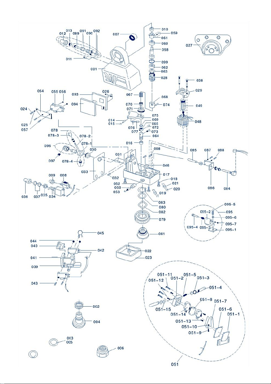
- 12 -

- 13 -

- 14 -
PARTS LIST
PROBLEEM
REDENEN EN OPLOSMIDDELEN
De LICHT
TRANSMISSIE doet
dat niet gloed.
1. Er is iets mis met de voeding of de
draadverbinding.
2. De STROOMONDERBREKER is beschadigd.
3. AAN-UITSCHAKELAAR (034) staat niet in de
"AAN"-stand of
beschadigd.
4.Als de motor kan bewegen, dan is de
LICHTTRANSMITTER is beschadigd
De motor doet het
niet
werk bij het duwen
CONTROLE
HENDEL (078) ofwel
links of Rechts .
1. Wanneer u op de SNELHEIDSKNOP (012)
drukt,
de motor draait:
①SNELHEIDSREGELKNOP staat niet in de
"0"-stand ②POTENTIEMETER (084) kan niet goed
werken
③CIRCUIT BOARD(003) is beschadigd.
2. Wanneer u op RAPID SPEED drukt KNOP(012),
de motor draait niet:
①De BORSTEL en de ROTOR raken elkaar niet
goed of de BORSTEL is opgebruikt
②Het circuit binnenin is verbroken.
Stroomlek
1. Er is kortsluiting in de BORSTEL (050) En de
BUITENKAP (017) van de stroomtoevoer of
er is kortsluiting in de EINDSCHAKELAAR (051). 2.
Het koolstofpoeder uit de BORSTEL resulteert in
kortsluiting.

- 15 -
Sanven Technologie Ltd.
Adres: Suite 250, 9166 Anaheim Place, Rancho Cucamonga, CA 91730
Gemaakt in China


- 17 -
Teknisk Support och e-garanticertifikat
www.vevor.com/support
KVARNKRAFTBORDSMATNING
MODELL: AL-260 AL-310
We continue to be committed to provide you tools with competitive price.
"Save Half", "Half Price" or any other similar expressions used by us only represents an
estimate of savings you might benefit from buying certain tools with us compared to the major
top brands and does not necessarily mean to cover all categories of tools offered by us. You
are kindly reminded to verify carefully when you are placing an order with us if you are
actually saving half in comparison with the top major brands.

- 1 -
MODELL: AL-260 AL-310
Have product questions? Need technical support? Please feel free to
contact us:
Technical Support and E-Warranty Certificate
www.vevor.com/support
NEED HELP? CONTACT US!
This is the original instruction, please read all manual instructions
carefully before operating. VEVOR reserves a clear interpretation of our
user manual. The appearance of the product shall be subject to the
product you received. Please forgive us that we won't inform you again if
there are any technology or software updates on our product.
MILL POWER TABLE FEED

- 2 -
BRIEF INTRODUCTION
Välkommen att använda detta kraftflöde. Det kommer att göra ditt jobb
bekvämt och göra dig lycklig. Läs denna bruksanvisning noggrant för din
montering och användning av denna maskin.
Lämplig för alla vertikala tornfräsmaskiner, inklusive men inte begränsat till
Bridgeport, precision Matthews,grizzly,enco,jet,sharp,Webb,GMC,
Clark,supermax,turn pro,vectrax,acra,Birmingham,accu,first och mer,Om
du fräser med samma installationsläge och 5/8" diameter axel vid slutet.
Så länge det är en maskin av Bridgeporttyp bör den vara lämplig.(den är
inte lämplig för fräsmaskiner med olika installationslägen eller bly skruvar i
olika storlekar, som powermatic och några andra maskiner i konstiga
storlekar, så se till att din maskin är den typiska Bridgeport-typen ovan)
SAFETY WARNING&CAUTIONS
1. Håll arbetsområdet rent. Använd inte maskinen på fuktiga, våta platser.
Använd inte maskinen i närheten av brandfarliga gaser eller vätskor.
2. Strömkällan måste samordnas med strömmatningen.
3. SWITCH(034) ska vara i läge "OFF" när den inte används eller innan
den ansluts.
4. Placera inga andra saker på maskinen. Undvik att vatten eller andra
vätskor stänker på maskinen.
5. Använd inte olämpliga tillbehör i ett försök att överskrida verktygets
kapacitet
6. Underhåll verktygen med omsorg.

- 3 -
SPECIFICATIONS
Modell
Hastig
het
Maximal
Återvända Hastighet
Maximal
vridmomen
t
Spänning
AL-260
0~ 20
0
2 77 varv/min
1385 mm/min (extern
skruvledning 5 mm)
450 in-lb
110V(220V-240
V)50/60Hz
AL-310
0~ 20
0
2 77 rpm
1385 mm/min (extern
skruvledning 5 mm)
450 in-lb
110V(220V-240
V)50/60Hz
AL-450
0~ 20
0
2 77 rpm
1385 mm/min (extern
skruvledning 5 mm)
450 in-lb
110V(220V-240
V)50/60Hz
UNPACK
Projektbeskrivning
Kvantitet
Kugghjulspackning av koppar
1
Montera hållarplattan
1
Inre lagerbana
1
Justerar shim
15
Gränslägesbrytare vattentät låda
1
Gränslägesbrytare fjäder
2
Begränsa block
2
Monteringsskruv
3
Kopparredskap
1

- 4 -
DRIVE UNIT INSTALLATION
Steg 1: Ta bort HANDVEV,
VÄVSKIFT och LAGERFLÄNS
från höger sidan av bordet.
Steg 2: Installera
kraftmatningen med
ADAPTERN(027) till platsen för
LAGER FLÄNS. Montera
ADAPTERN på bordsänden
med hjälp av fyra sexkanter.
skruvar. Detta bör göras
tillsammans med steg 3 för att
få rätt ledskruvens läge.
Steg 3: Skjut den INRE
RINGEN(007) över bordets ledarskruv och sedan in i hålet på
kraftmatningens nållager. Äntligen ska den INRE RINGEN nudda
ledarskruvens skuldra. Gå tillbaka till figur 1(027 007)
Steg 4: Sätt in nyckeln i kilspåren på ledarskruven.
Steg 5: Smörj grafitbasfett på tänderna på BEVEL GEAR(004). Placera en
liten mängd fett på insidan av BEVEL GEAR FLÄNSEN.
Steg 6: Montera VÄXELVÄXELLT på ledskruven med nyckel och tryck upp
det mot.DRIVVÄXELLT (061).
Observera: Generellt bör du, innan du installerar BEVEL GEAR (004),
infoga flera SHIMS.(005)mellan INNER RING (007) och BEVEL
GEAR(004), så att du kan få minsta möjliga avstånd mellan växelenheten.
Kvantiteten av de SHIMS (005) du kommer att använda bestäms av din

- 5 -
testversion.
Se figur 1:005,004 osv.
Steg 7: Installera lämplig DIAL på BEVEL GEAR (CL004) enligt figur 1 och
nära kraftmatningsflänsen (Rör inte vid varandra!). Då kan du behöva flera
SHIMS (CL003) för att uppfylla ovanstående krav.
Steg 8: Skruva fast MUTTERN(002) i VÄXELVÄXELLT för att undvika att
ratten går lös.
Steg 9: Sätt tillbaka HANDVEVEN som togs bort i steg 1 på ledarskruven.
Och dra sedan åt BEVEL GEAR (004) eller så kan du använda
LÅSMUTTERN (006) för att dra åt den.
LIMIT ASSEMBLY INSTALL ATION
Strömförsörjningen är utrustad med GRÄNSBRYTAREMONTERING(051)
och TRAVLE STOPMONTERING(095). Dess montering är enligt följande
(se figur 2):
Steg 1: Ta bort den ursprungliga färdstoppsenheten på bordet och montera
RESAN STOPP MONTERING(B18) medföljer istället.
Steg 2: Ta bort det ursprungliga gränsblocket och montera
GRÄNSBRYTARE (B05) medföljer istället.
VARSEL
1、Se till att de två rörande topparna på GRÄNSBRYTARE MONTERING
(051) och stången på TRAVEL STOP MONTAGE(B18) bör vara på samma
axel.
2、RESAN STOPP MONTERING(095) bör installeras flera millimeter
mindre än stroken på grund av trögheten.
3、Skydda sladden till GRÄNSBRYTARE. Låt den inte lindas upp av rörelse
bitar eller bordet.
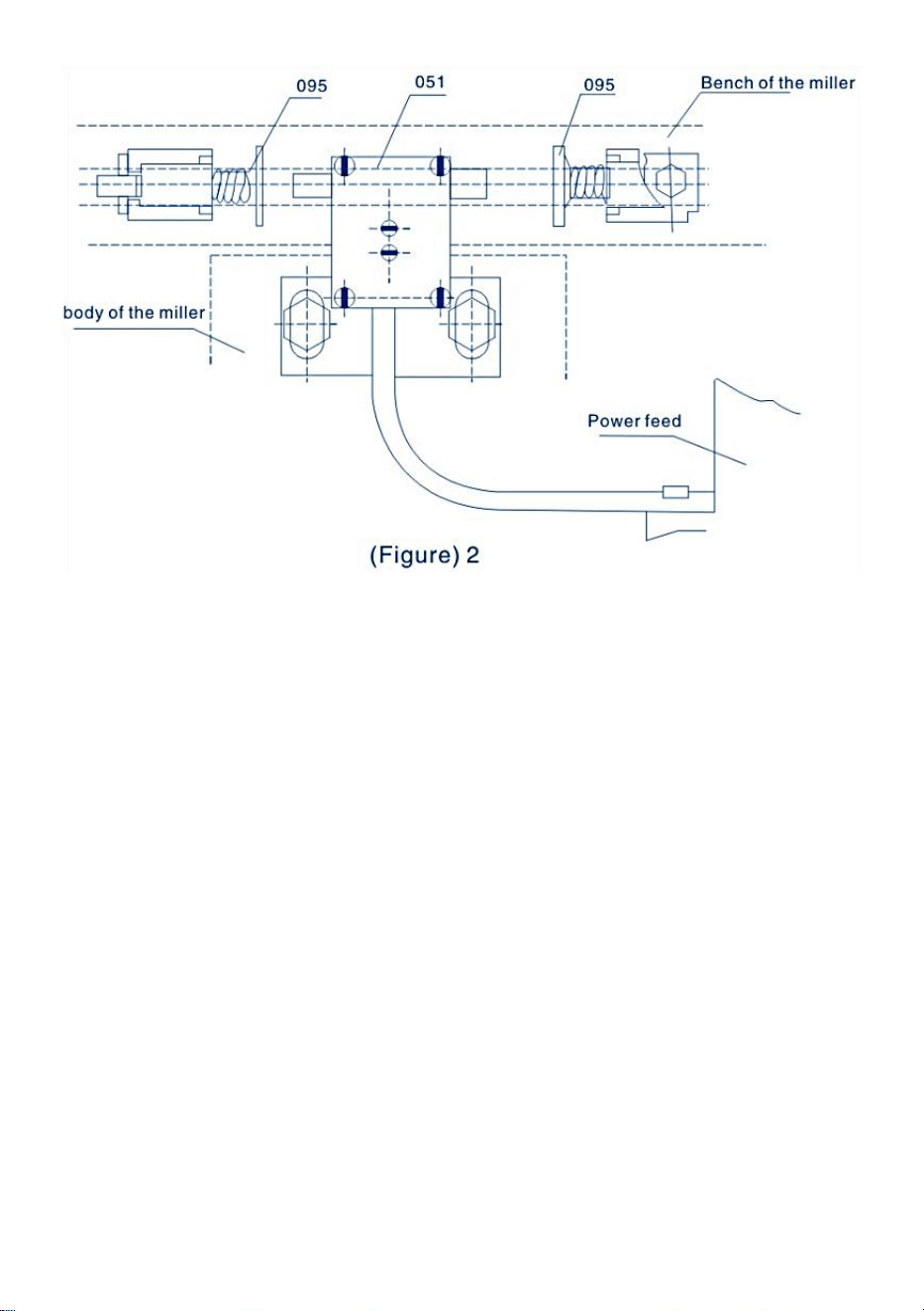
- 6 -
Driften av kraftmatningen är som följer (se figur 3):
Steg 1: Se till att PÅ-AV-BRYTARE (034) är i "OFF"-läget och att
KONTROLLHANDTAGSMONTERING (078) är i neutralt (mitt)läge.
Steg 2: Anslut strömbordets matningskabel till det föreskrivna uttaget.
Steg 3: Vrid PÅ-AV-BRYTARE till "ON"-position i på och sedan LIGHT
SÄNDARE(011)bör lysa.
Steg 4: Vrid på CONTROL HANDTA(078) bort från mittpositionen till en
riktning, då kommer bordet att flytta in samma riktning. Vrid på SPEED
KONTROLLKNAPP ASSY(096)medurs, därefter bordets rörelsehastighet
kommer att öka gradvis.
Steg 5: Om du vill ändra rörelseriktningen för bordet, vänligen vrid på
KONTROLLHANDTAG till mittläget tills kraftmatningen stannar. Och då
kan du sväng KONTROLLHANDTAGET in riktningen du vill.
(Se till att kraftmatningen stoppas innan du ändrar riktning)
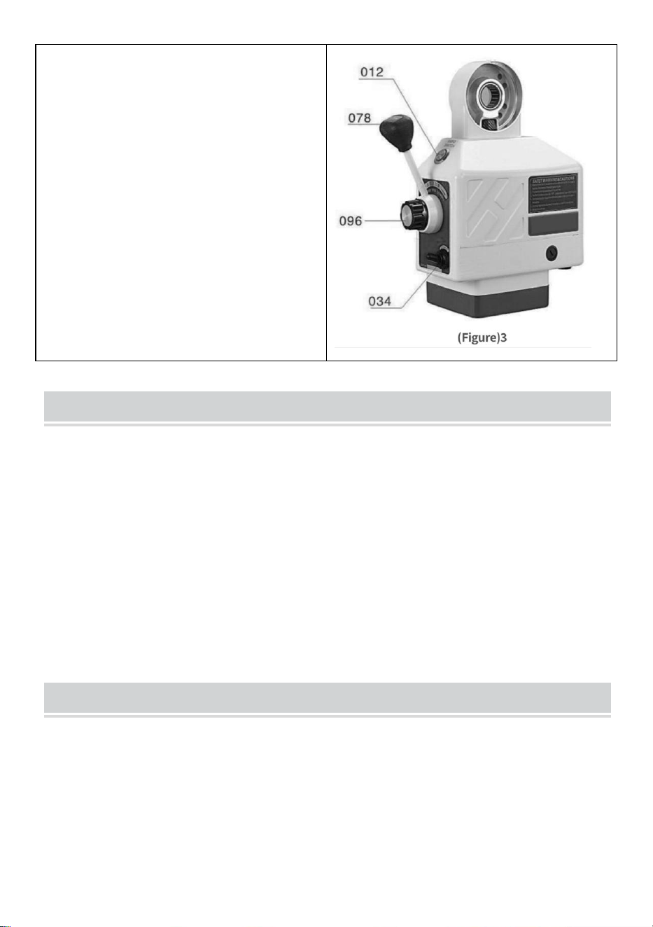
- 7 -
VARSEL
1 . Hastigheten styrs av SPEED
KONTROLLVRED ASSY(B19).
Läge "o" representerar" stopp" och
"g" representerar den högsta
hastigheten.
9. SNABBKOPPLINGSKNAPP
(012) är för snabb rörelse av bordet
När den trycks ned, då kommer
bordet att röra sig i hög hastighet.
PERIODIC MAINTENANCE
1、Rengör maskinen var 250:e timme, såsom rotorriktningsändring, kol inuti
maskinen och annan smuts så att isoleringen kan säkerställas.
2、Smörjning. Sätt i smörjolja i kugghjulen och smeta ut grafitbasfett på
kugghjulens tänder
PEPLACEMNTOF BRUSH
Steg 1: Ta bort BORSTHÅLVA(053)(Se figur 4). Då kan BORSTE(050)
springa ut. Lossa inte BORSTEN. Om BORSTEN inte fjädrar ut, ta
försiktigt bort BORSTEN med spetsen på din skruvmejsel.
Steg 2: Undersök den konkava ytan på BORSTEN. Ytan ska vara slät och
ren. Om du hittar stora repor märken i BORSEN eller att delar av
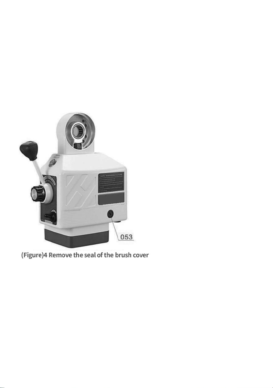
- 8 -
BORSTEN har gått av eller längden kvar av BORSTEN är endast 6 mm,
byt ut BORSTE omedelbart med en godkänd ersättningsBORSTE. Om
BORSTEN bara är smutsig kan du rengör BORSTEN med en penna
radergummi. Rensa bort alla bitar av suddgummi kvar på BORSEN.
Steg 3: Det finns en fjäder- och mässingskontakt bunden till BRUSH.Vrid
på MÄSSINGSKOPPLING tills stiften är vertikalt och tryck in BORSTEN i
BORSTHÅLLARE(052). Trä på BORSTHÅLLARE i BORSTHÅLLARE och
dra åt.
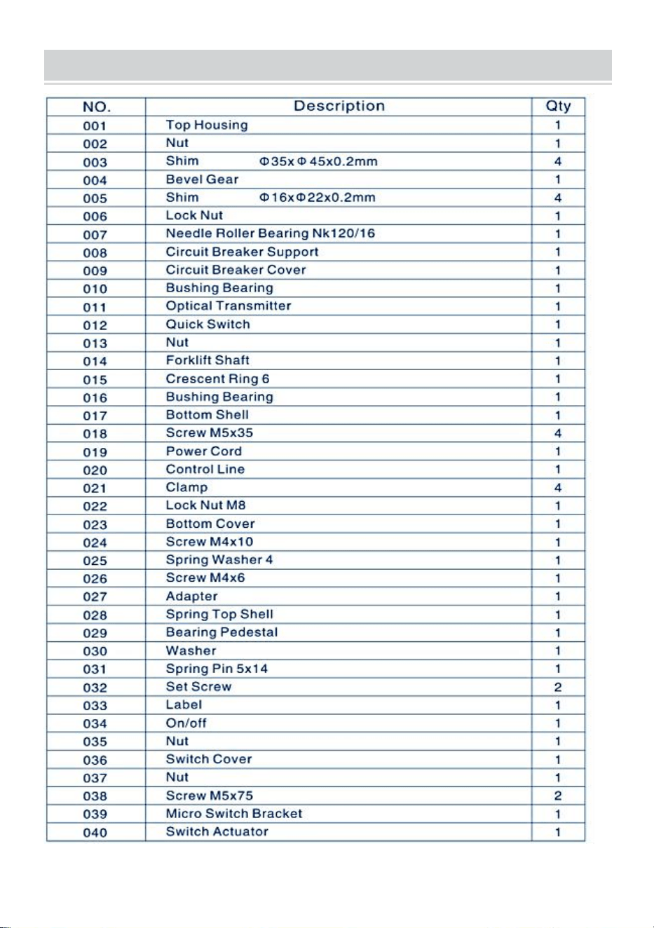
- 9 -
PARTS LIST

- 10 -

- 11 -
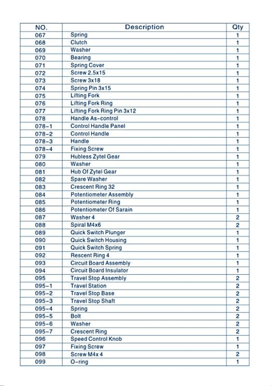
- 12 -

- 13 -
PARTS LIST
PROBLEM
R ESONER OCH LÖSNINGMEDEL
Det gör inte LIGHT
TRANS MITTER
glöd.
1.Det är något fel på strömförsörjningen eller
tråden ansluter.
2. KRETSBRYTARE är skadad.
3.PÅ-AV-BRYTARE (034) är inte i läge "PÅ" eller
skadad.
4.Om motorn kan röra sig, då
LJUSSÄNDARE är skadad
Motorn gör det inte
arbeta när du trycker
KONTROLLERA
HANTERA (078)
antingen vänster
eller Rätt .
1.När du trycker på RAPID
SPEED-KNAPPEN(012),
motorn roterar:
①HASTIGHETSKNAPPEN är inte i läge "0"
②POTENTIONSMÄTARE (084) kan inte fungera
korrekt
③KRETSKORT (003) är skadat.
2.När du trycker på RAPID SPEED BUTTON(012),
de motordosen roterar inte:
①BORSTEN och ROTORN berörs inte
korrekt eller så är BORSTEN förbrukad
②Kretsen inuti är bruten.
Aktuellt läckage
1. Det är kortslutning över BORSTEN (050) och
strömmatningens YTTRE KÅP(017) eller
det är kortslutning i GRÄNSBRYTARE (051). 2.
Kolpulvret från BRUSH resulterar i
kortslutning.

- 14 -
Sanven Technology Ltd.
Adress: Suite 250, 9166 Anaheim Place, Rancho Cucamonga, CA
91730
Tillverkad i Kina

