

Powerfeeder Operating Instruction
For your safety, please read Operating Instruction before operating the machine.

2
● IMPORTANT SAFETY RULES
WARNING: Failure to follow these rules may result in serious personal injury.
Woodworking can be dangerous if safe and proper operation procedures are not followed. Using the tool
with respect and caution will considerably lessen the possibility of accident. Always follow rules. Use
common sense and exercise caution in the workshop. Remember: your personal safety is your
responsibility.
1. READ OPERATION MANUAL. Keep and protect it near the machine for easy access in the event of future
review.
2. IMPORTANT PERSONAL SAFETY NOTE.
Wear goggles – eyes protection.
Wear dust masks – respiratory protection.
Wear earpieces – hearing protection.
Wear proper apparel – no loose clothing, gloves, neckties, and jewelry.
No drugs, alcohol, medication – Do not operate under such influence.
3. DON'T USE TOOL IN DANGEROUS ENVIRONMENT. Keep work area well ventilated and lighted, avoid damp
or wet location. Room temperatures -10~+40℃, Humidity 30~95%RH, Altitude ≦1000M, Voltage deviation
±5%.
4. KEEP WORK TABLE AND AREA CLEAN. Loose hand tools left on table or cluttered work area invite accidents.
5. KEEP UP THE MAINTENANCE. Follow operation manual for proper operation and maintenance.
6. DISCONNECT TOOL FROM POWER SOURCE. Before any tooling change, repairing or regular maintenance.
7. FINAL INSPECTION AFTER EACH MAINTENANCE OR REPAIRING. Make sure all parts are properly mounted,
tightened, and aligned before next operation.
8. AVOID UNINTENTIONAL STARTING. Make sure switch is on “OFF” position before power reconnection.
9. KEEP WORK SHOP CHILDPROOF. Use padlocks, master switches or remove starter keys. Prevent children or
unauthorized personal from tampering. All visitors should be kept at a safe distance from work area.
10. NEVER LEAVE TOOL RUNNING UNATTENDED. Turn power off. Don’t leave until it comes to a complete stop.
● ADDITIONAL SAFETY RULES FOR POWERFEEDER
1. Cutting tools MUST be rotating before feeding.
2. DO NOT overload the cutting tool by feeding too fast.
3. ALWAYS KEEP hands away from rotating parts.
4. PROVIDE support for long stock on out feed end of table.
5. STOP the feeder before stopping the cutting tool.
6. DISCONNECT power before making repairs or adjustment.
3
x4 sets
of bolt
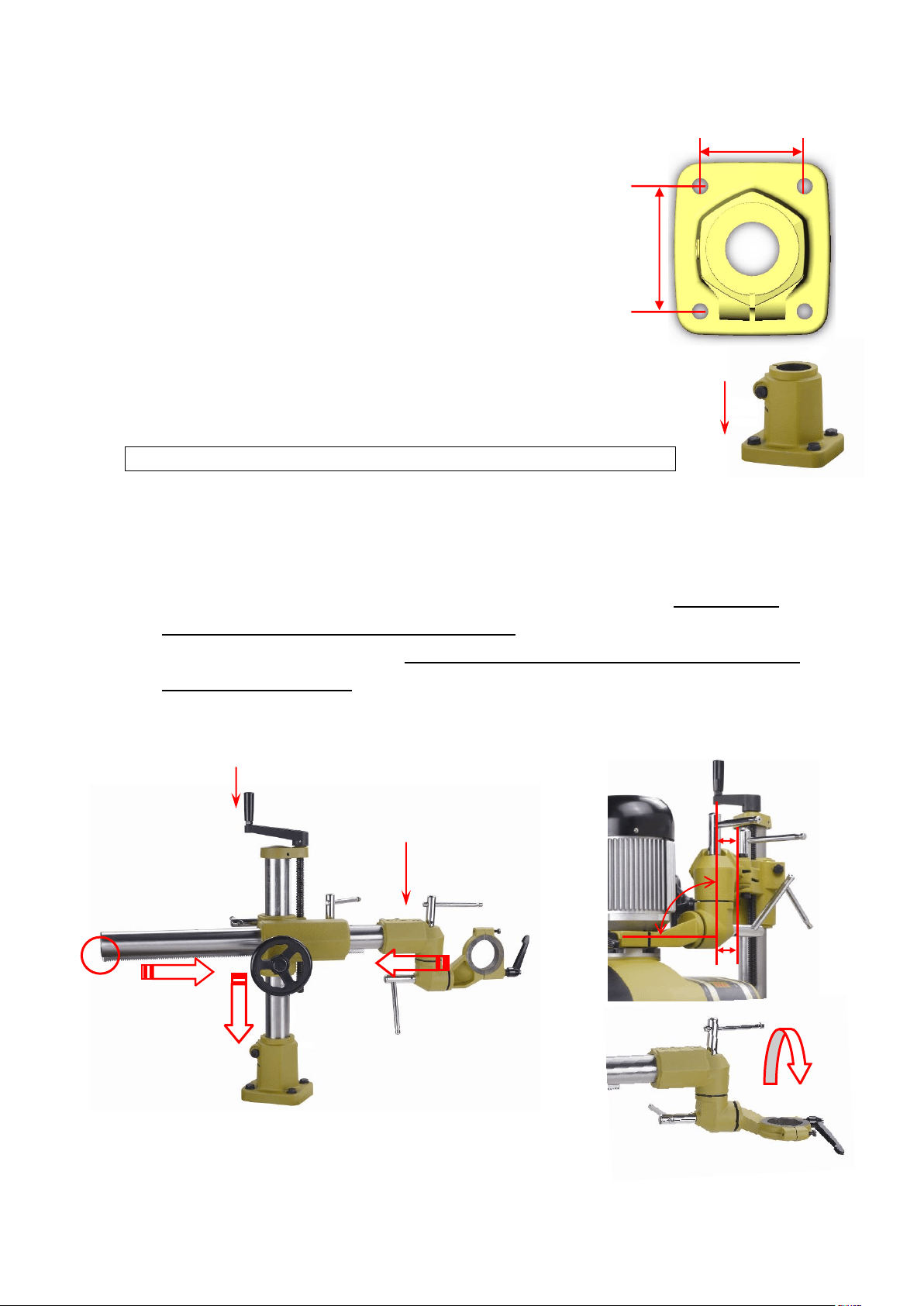
● LOCATE MOUNTING AND BORING POSITION
Suggested position at the outfeed rear end of the
tabletop.
1. Center punch 4 boring positions 90x108mm. (Avoid
table ribs and support underneath the table.)
2. Drill φ10.3~10.5mm & tap M12-P1.75.
3. Using 4 sets of bolts, M12x50mm, & spring washers
(provided,) mount the Base on tabletop.
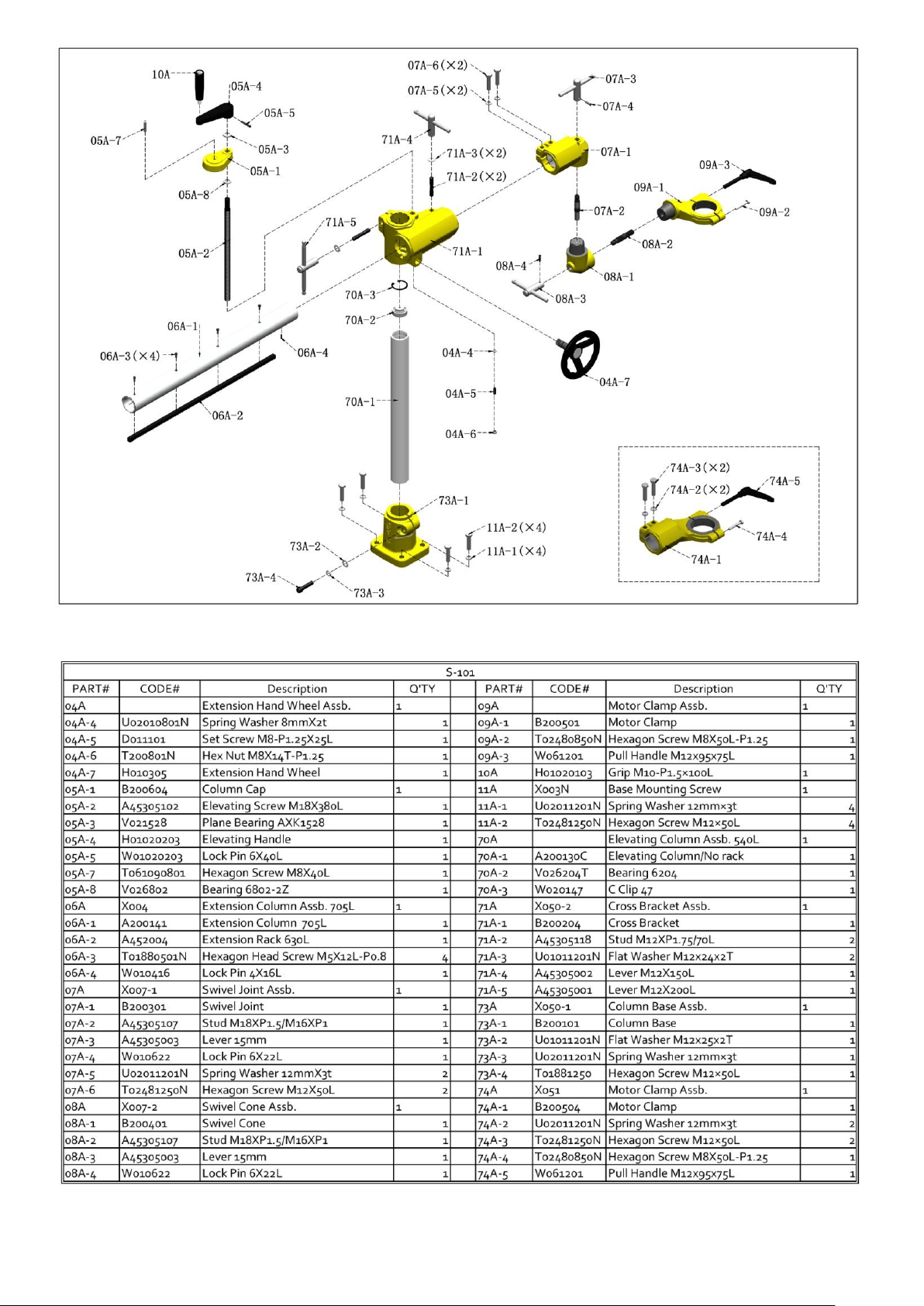
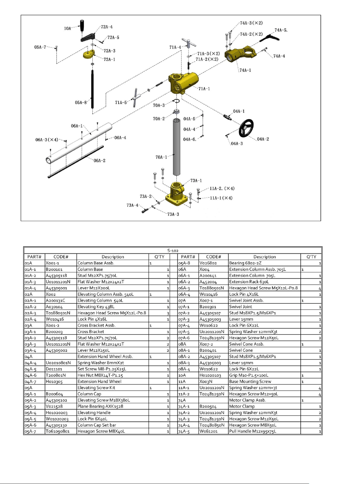
● ASSEMBLING
WARNING: Get help! Feeder is heavy; do not try to do it on your own.
1. Fasten Base to table. Insert Elevating Column Assb. to Base, assemble Grip.
2. Insert Extension Column into Cross Bracket. Turn Handwheel a few turns, tighten Lever.
3. Assemble the Universal Joint to the end of Extension Column. Make sure of its vertical
parallel with the Elevating Column, and semi-tighten the 2 Screws. Remarks: the
parallelism relates to feeding roller alignment.
4. Adjust Motor Clamp to the left; make sure it is parallel to table top, which relates to
feeding roller alignment..
5. Reposition Motor 270° by loosen 4 Screws let Switch position in the front.
90mm
108mm
90°
x2 sets of
Screw
4
Cutter
Outfeed
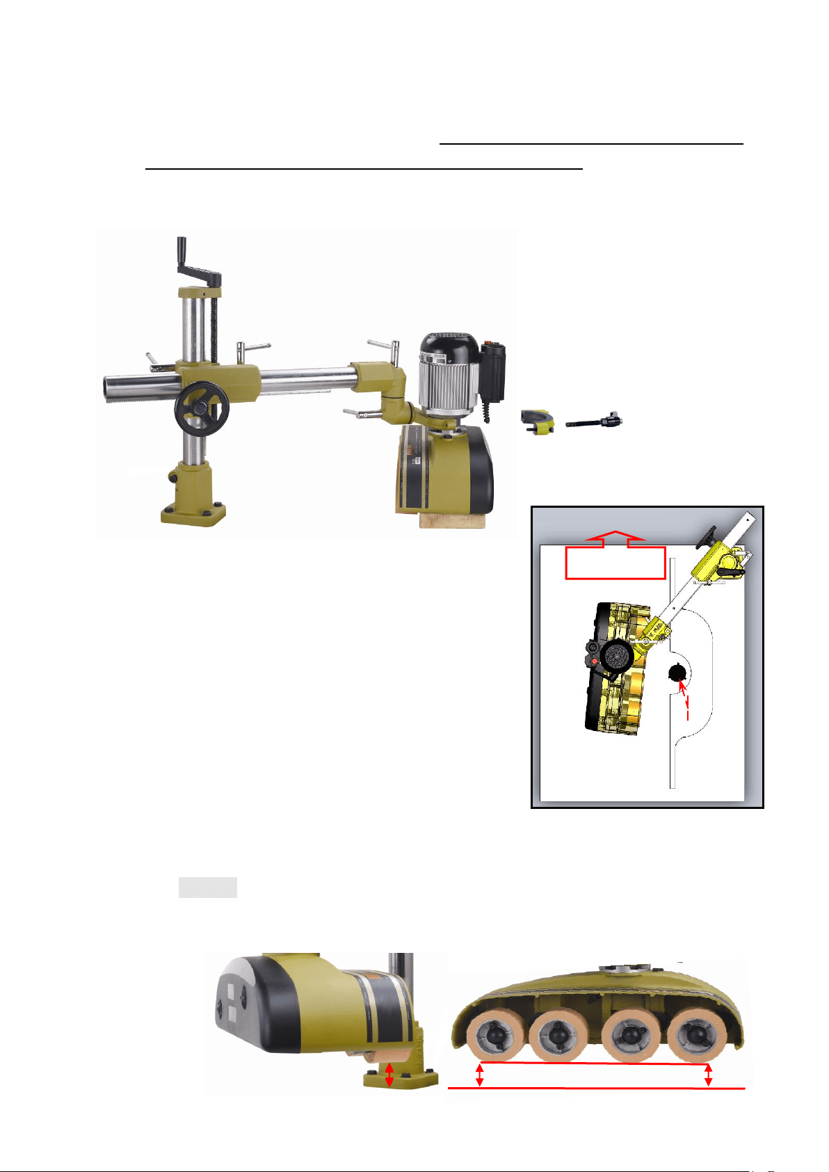
6. Remove outer-half Motor Clamp, place feeder housing to the inner-half Motor Clamp
and assemble the outer-half Motor Clamp. The parallelism between Motor Clamp open
sides and feeder housing relates to top-side feeding conversion. Make the same
open-space between 2 half Motor Clamp will be convenient for feeder housing
horizontal rotation.
○
1
○
2
○
3
● FEEDING POSITION & ROLLER PARALLELISM
ADJUSTMENT
1. Loosen all Levers ○
1
、○
2
、○
3
, move feeder housing
and make it right in front of the cutter and parallel to
the fence. Adjust feeding angle with outfeed end
slightly against the fence. Tighten all Levers ○
1
、○
2
、
○
3
,and Handle.
2. Low down feeder housing let rollers slightly touch
table top to adjust roller parallelism.
2.1. Adjust horizontal of the Motor Clamp for infeed
end and outfeed end parallelism.
2.2. Adjust angle of the Swivel Bracket for rear side and front side parallelism.
Remark: Roller alignment slightly off is acceptable, offset by independent
suspension.

5
3. Make sure all Levers, Screws and Handles are tightened.
4. Important: There is certain play between Elevating Key and Bracket Groove
designed for easy elevation. Pull feeder housing against infeed direction and tighten all
levers to offset the play and ensure sturdy feeding.
● ADJUSTMENT AND CONTROL
1 ○
2
○
A
------------------
2 ○
2
、○
2
○
A
------
3 ○
3
、○
3
○
A
----------
4 ○
4
○
A
---
5 ○
5
○
A
----------------
6 ○
6
○
A
------
7 ○
7
○
A
---------------------
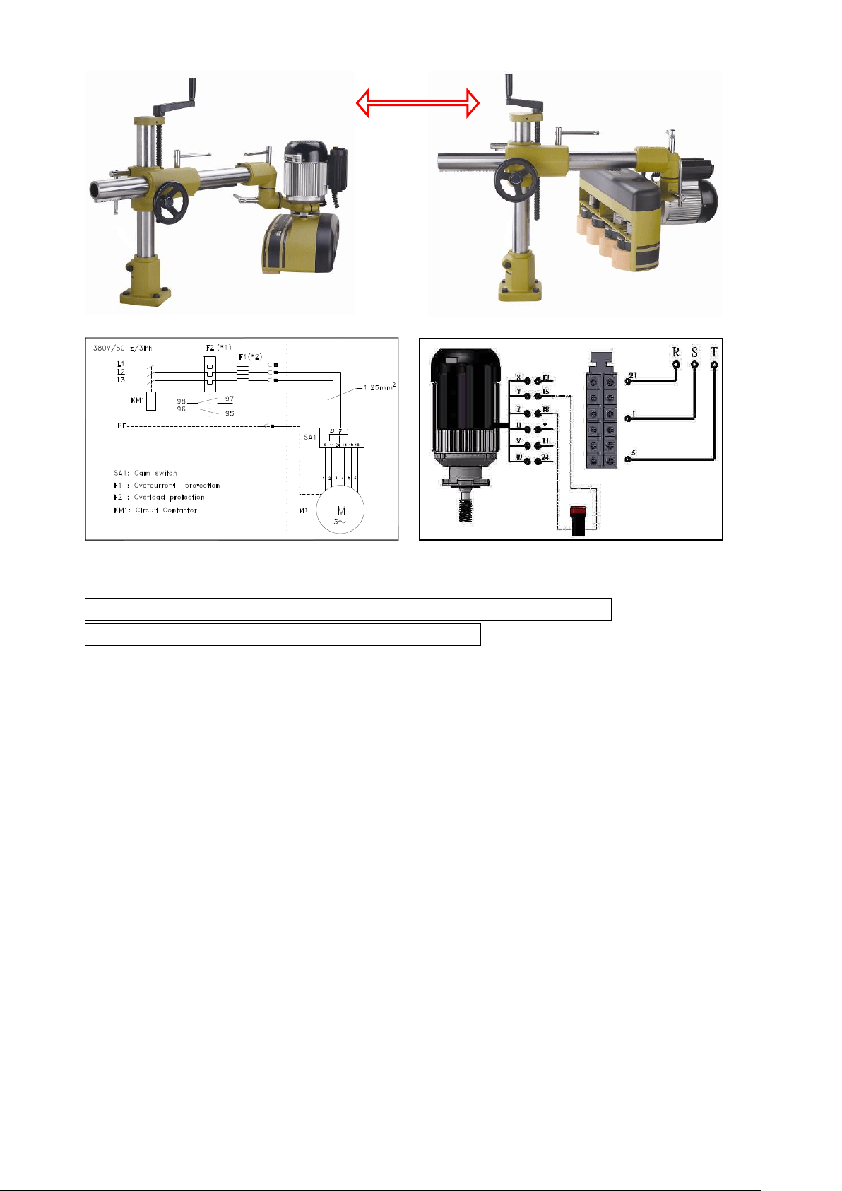
● TOP TO SIDE FEEDING CONVERSION
1. Swing feeder housing off the tabletop area. (Weight balance between feeder and the
machine must be considered.) Loosen Lever○
5
, left-turn feeder housing 90°to floor
with roller on right and motor on left, tighten Lever○
5
. Loosen Pull Handle on Motor
Clamp, turn feeder housing 90° with Switch Box facing up and roller facing down, and
tighten Pull Handle.
2. Loosen Lever○
4
, push feeder housing to desired position. Secure all Levers, Screws and
Handles.
○
2
○
3
○
4
○
6
○
5
○
2
○
3
○
7 Screw x2
6
○
4
○
5
● POWER CONNECTION AND GROUNDING
WARNING: Make sure electric currency matches the motor specification.
WARNING: Make sure switch is on the “OFF” position.
CE REQUIRED COUNTRIES:
1. Feeder is a supplemental tool, which works in conjunction with your shaper, table saw,
jointer, … etc. It’s recommended to be used with a machine that is wired in compliance with
your national or local electrical regulation.
2. It must be connected to your machine through a specially designed current taps that ensures
your machine’s switch and emergency stop having controls of your feeder’s power source. In
addition, the current tap must provides an overload and under voltage protection systems.
3. Rated Current: 2.5Amp.
4. Electrical connection is reserved for certified electrician only.
OTHER COUNTRIES:
1. A separate electrical outlet should be used for your feeder. The circuit should not be less than #
12. Wire properly installed and grounded in accordance with your local codes and ordinances,
protected with a 15 Amp time lag fuse or circuit breaker.
7
2. If an extension cord is used; ≦30M (100Ft), use #12 Wire; ≧46M (150Ft), use #10 Wire.
3. Ensure all line connections make good contact. Low voltage running will damage the motor.
4. Properly ground the motor to reduce the risk of electrical shock. The motor is equipped with a
grounding conductor (green wire with or without yellow stripes.)
5. If unsure, consult with a qualified electrician.
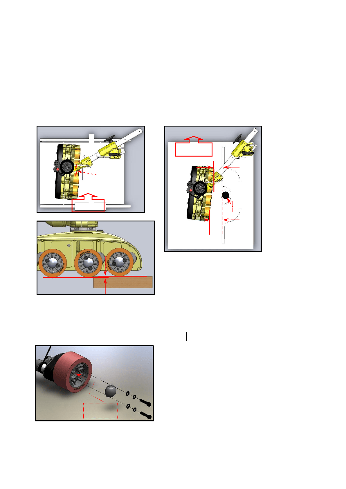
● USING POWERFEEDER ON MACHINES
● ROLLER REPLACEMENT
WARNING: Disconnect feeder from power source.
Grease
Saw
Infeed
A
B
Cutter
Outfeed
B-A= 3~5 mm
3~4mm
8
Change Oil
Grease
● FEED RATE SETTING
WARNING: Disconnect feeder from power source.
Setting the available feed rate is a combination of motor speeds (pole change by switch, forward or
reverse) & gear settings (build in 40T/25T, equipped with 21T/44T,) total 8 speeds. Feed rate chart is
shown on roller cover at the infeed end.
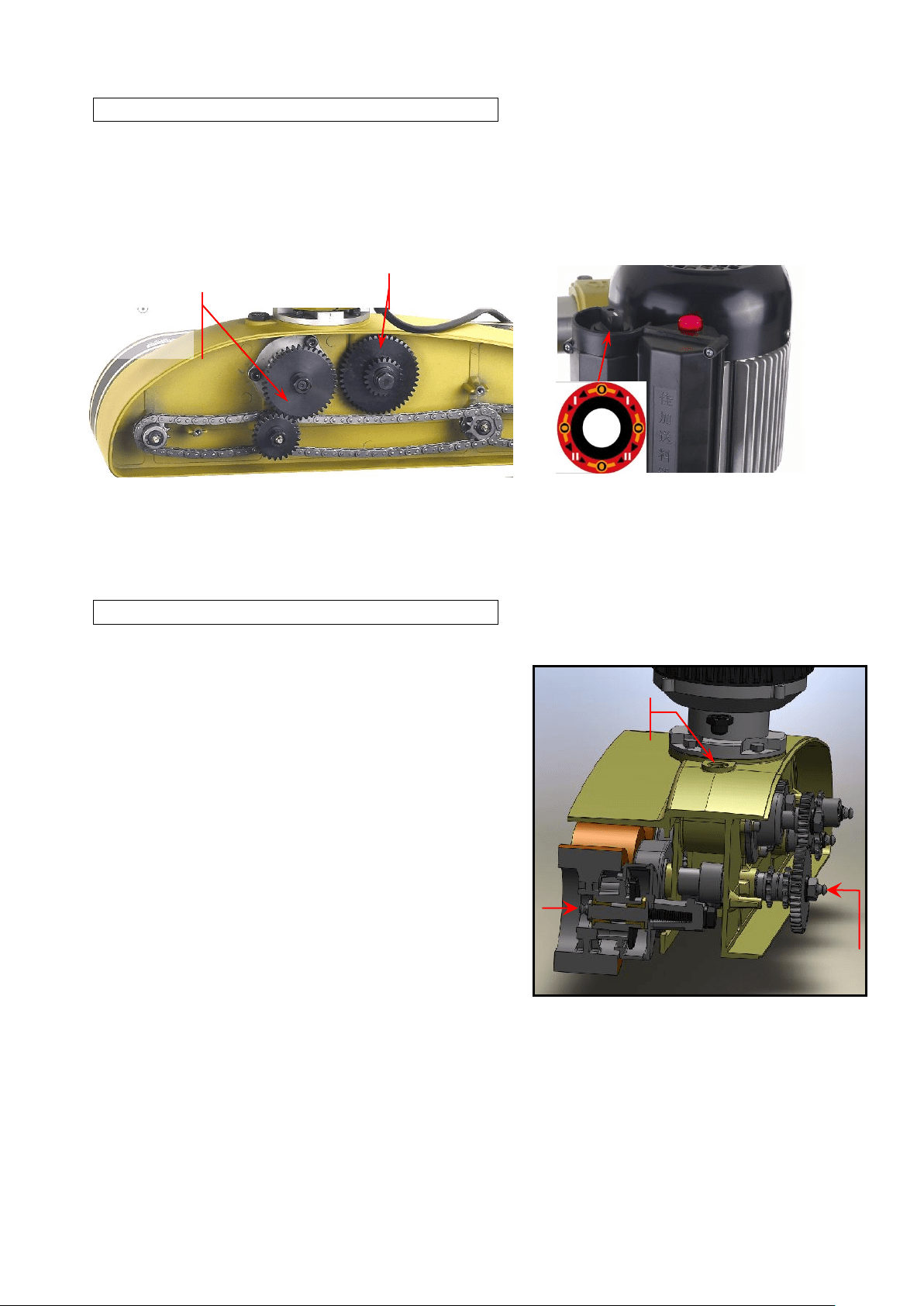
● LUBRICATION & MAINTENANCE
WARNING: Disconnect feeder from power source.
Change oil first 200 hrs (30 days,) and change oil every
1000 hrs (6 months.) Recommended Gear Oil: MOBIL
Mobilgear 630, Shell/Omala 150 BP, Energol GR-XP 150,
or equivalents.
Grease every 200 hrs (30 days) through fittings, using
grease gun. Recommended Grease: # 2 GREASE.
(Shell – Alvania Grease R2 or equivalents.)
Lubricate gears & chains periodically with grease.
Recommended Grease: # 2 GREASE. (Shell – Alvania
Grease R2 or equivalents.)
Remove working-waste (saw dust, shavings, etc) from the feeder by air gun after each use.
Build-in
40T/25T
21T/44T

9

10
● SERVICE AND TROUBLESHOOTING
● 1-YEAR LIMITED WARRANTY
1 Manufacturer warrants its product free from any manufacturing defects, excluding rollers or belts which
wear under normal usage.
2 Manufacturer is not liable for freight damages, power source damage, nor damages caused by improper
use of machine and failure in keeping up with the recommended maintenance.
3 Warranty service with free replacement parts only. Bar code number must be presented for any warranty
service.
4 Manufacture’s Manufacturing Resume System (MRS) contains 2 sets of bar code, motor, feeder housing
and stand.
4.1 Motor bar code on motor specification plate, which is
traceable to the Motor Pernformace Report (MPR)
enclosed in feeder packaging.
4.2 Housing bar code on outfeed end of roller cover and the
packaging.
5 For any questionable parts, manufacturer or the dealer has the
right requesting for return of the defected parts, freight collect;
a claim form must be signed and attached to the parts.
#.
TROUBLE PROBABLE CAUSE SOLUTION
1.
Jammed workpiece Rollers too low. Raise feeder.
2.
Uneven forwarding speed. Rollers too high, no traction. Lower feeder.
Occational jammed workpiece.
Relatively thicker piece in
the pile.
Put aside the thicker pieces, re-adjust the
height afterwards.
4.
Occational slip or uneven
forwarding speed.
Relatively thinner piece in
the pile.
Push it out by using the next piece, put aside
the thiner pieces, re-adjust the height
afterwards.
5.
Side feeding.
Refer to manuel on top to side feeding
conversion.
6.
Uneven cut or finish. Insufficient roller pressure. Lower feeder.
7.
Uneven cut or finish.
Insufficient angle of feeding
direction against fence.
Infeed-end (housing) must be 3-5mm further
(away) from fence than outfeed-end.
8.
Rough finish. Hight moisture contain.
9.
Infeed speed varies from
outfeed speed.
Rollers may not be evenly
paralleled to table.
Re-adjust position.
10.
Rought or burned cuts. Feeding too fast. Adjust feed rate.
11.
Rought or burned cuts. Dull cutter. Change or sharpen cutter.
12.
Workpiece not moving straight
forward and against fence.
Incorrect angle of feeding
direction against fence.
Infeed-end (housing) must be 3-5mm further
(away) from fence than outfeed-end.
13.
Uneven feeding speed still,
after all porper adjusment,
May occur on certain type of
materials.
Apply softer roller (higher friction) or
pushing it forward with the next workpiece.
14.
improper processing sound ~1. Feed too fast. Adjust feed rate.
15.
improper processing sound ~2. Dull cutter. Change or sharpen cutter.

11

12

13

14
15
16