
Technical Support and E-Warranty Certificate
www.vevor.com/support
MILL POWER TABLE FEED
MODEL:AL-450
We continue to be committed to provide you tools with competitive price.
"Save Half", "Half Price" or any other similar expressions used by us only represents an
estimate of savings you might benefit from buying certain tools with us compared to the major
top brands and does not necessarily mean to cover all categories of tools offered by us. You
are kindly reminded to verify carefully when you are placing an order with us if you are
actually saving half in comparison with the top major brands.

- 1 -
MODEL:AL-450
Have product questions? Need technical support? Please feel free to
contact us:
Technical Support and E-Warranty Certificate
www.vevor.com/support
NEED HELP? CONTACT US!
This is the original instruction, please read all manual instructions
carefully before operating. VEVOR reserves a clear interpretation of our
user manual. The appearance of the product shall be subject to the
product you received. Please forgive us that we won't inform you again if
there are any technology or software updates on our product.
MILL POWER TABLE FEED

- 2 -
BRIEF INTRODUCTION
Welcome to use this power feed.It will make your job convenient and make
you happy. Please read this manual carefully for your assembly and use of
this machine.
Suitable for any vertical turret milling machine feeders,including but not
limited to Bridgeport, precision Matthews,grizzly,enco,jet,sharp,Webb,GMC,
Clark,supermax,turn pro,vectrax,acra,Birmingham,accu,first and more,If
you mill with the same installation mode and 5/8"diameter shaft at the
end.As long as it is a Bridgeport type machine,it should be suitable.(it will
not be suitable for milling machines with different installation modes or lead
screws of different sizes,such as powermatic and some other strange
size machines,so please make sure your machine is the typical Bridgeport
type above)
SAFETY WARNINGS AND PRECAUTIONS
1. Keep the work area clean. Do not use this machine in wet places. Do not
use this machine in the presence of flammable gases or liquids.
2. The power supply must be coordinated with the feed.
3. The switch (034) shall be in the“off' position before it is not used or
inserted
4. Don't put anything else on the machine. Avoid spilling water or other
liquids on the machine
5. Do not try to exceed the capacity of the tool by using inappropriate
attachments.
6. Maintain tools carefully.

- 3 -
SPECIFICATIONS
Model
Spee
d
Maximum
Return Speed
Maximum
torque
Voltage
AL-260
0~200
277RPM
1385mm/min (external
screw lead 5mm)
450in-lb
110V(220V-240
V)50/60Hz
AL-310
0~200
277RPM
1385mm/min (external
screw lead 5mm)
450in-lb
110V(220V-240
V)50/60Hz
AL-450
0~200
277RPM
1385mm/min (external
screw lead 5mm)
450in-lb
110V(220V-240
V)50/60Hz
OPEN THE BOX
Project description
Quantity
Copper gear gasket
1
Install the retainer plate
1
Flat key
1
Adjusting shim
15
Limit switch waterproof box
1
Limit switch spring
2
Limit block
2
Mounting screw
4
Copper gear
1
Extended shaft
1
Extended shaft spring
1
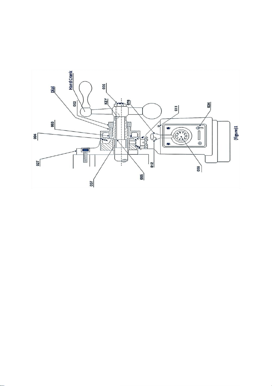
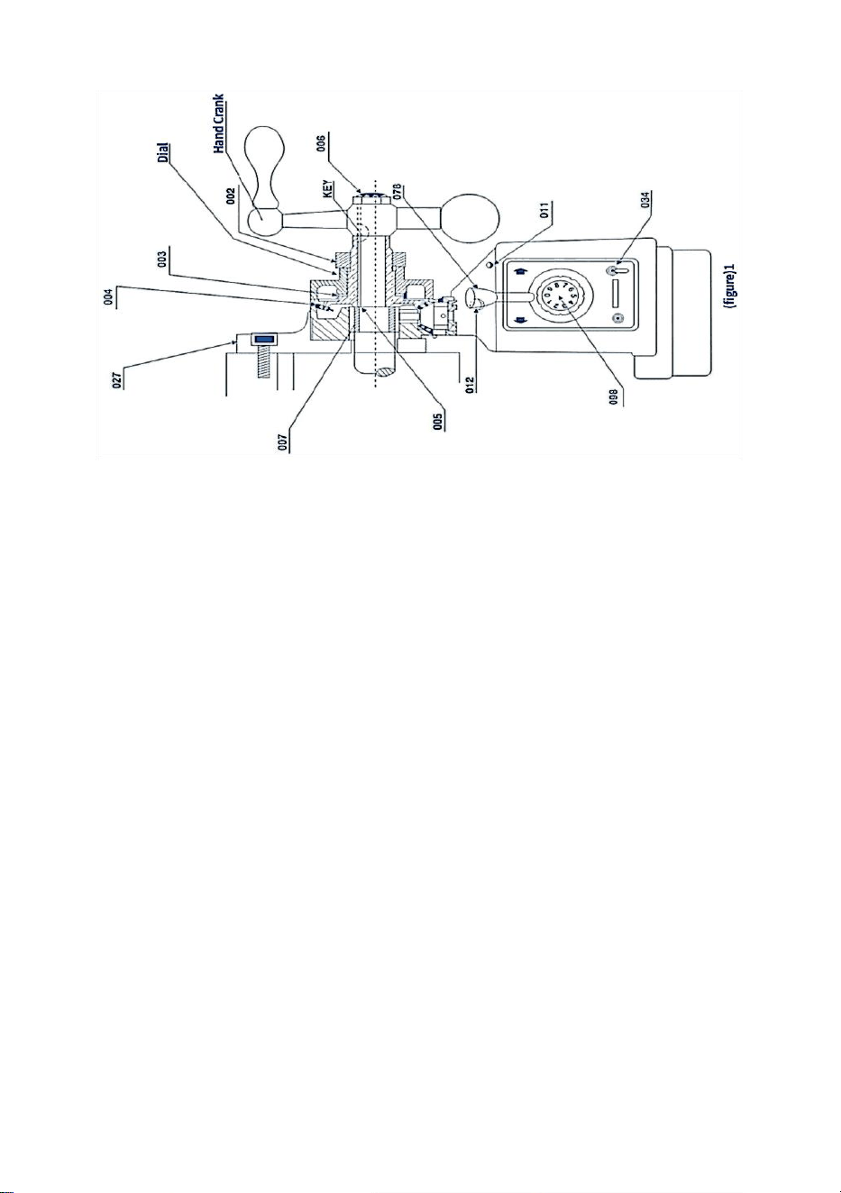
DRIVE INSTALLATION
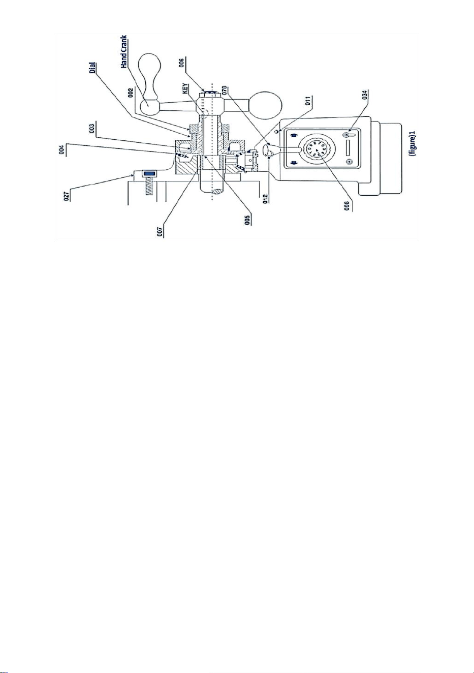
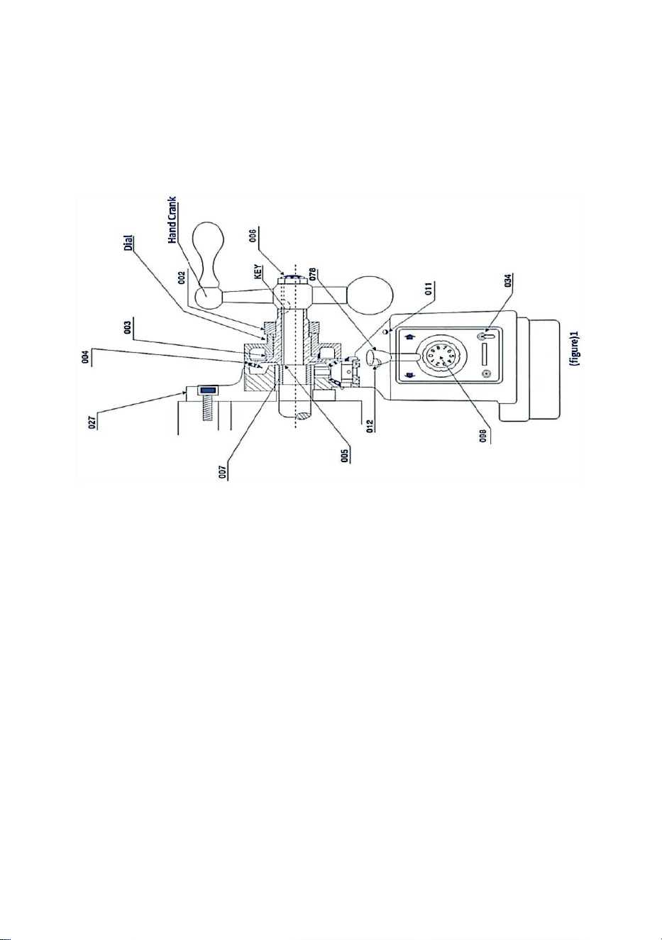
Step 1: remove the hand crank, dial, and bearing flange from the right side
of the table.
Step 2: Install the power feeder with the adapter (027) into the position of
the bearing flange. Assemble the adapter to the end of the table using four
hexagonal nuts. The screw, which should be completed with step 3,
ensures the correct position of the lead screw
- 4 -
Step 3: Slide the inner ring (007) onto the lead screw of the bench, and
then slide into the hole of the power feed needle roller bearing. Finally, the
inner ring should contact the shoulder of the lead screPlease return to
Figure 1(027007)
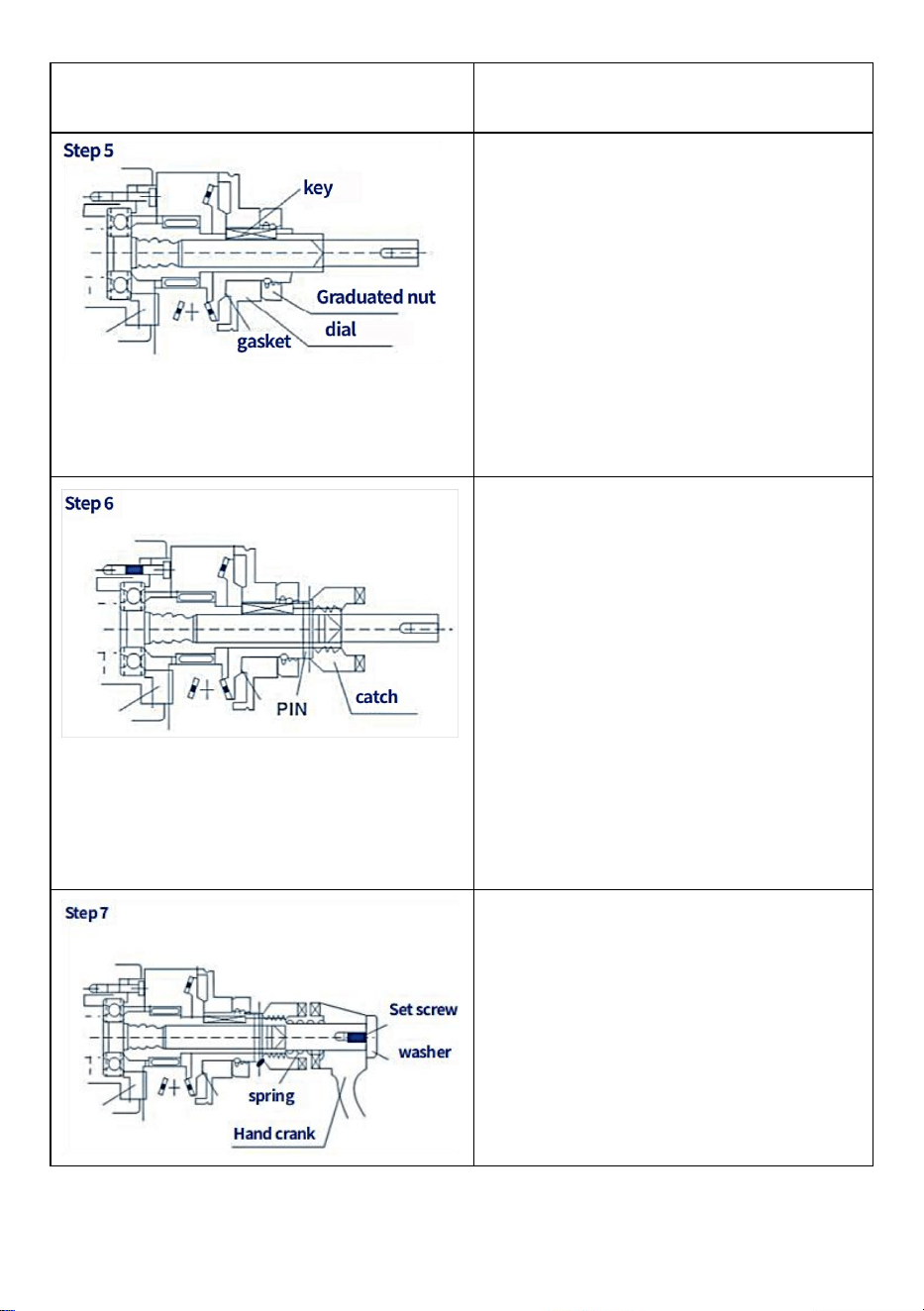
Step 4: Insert the key into the keyway on the lead screw
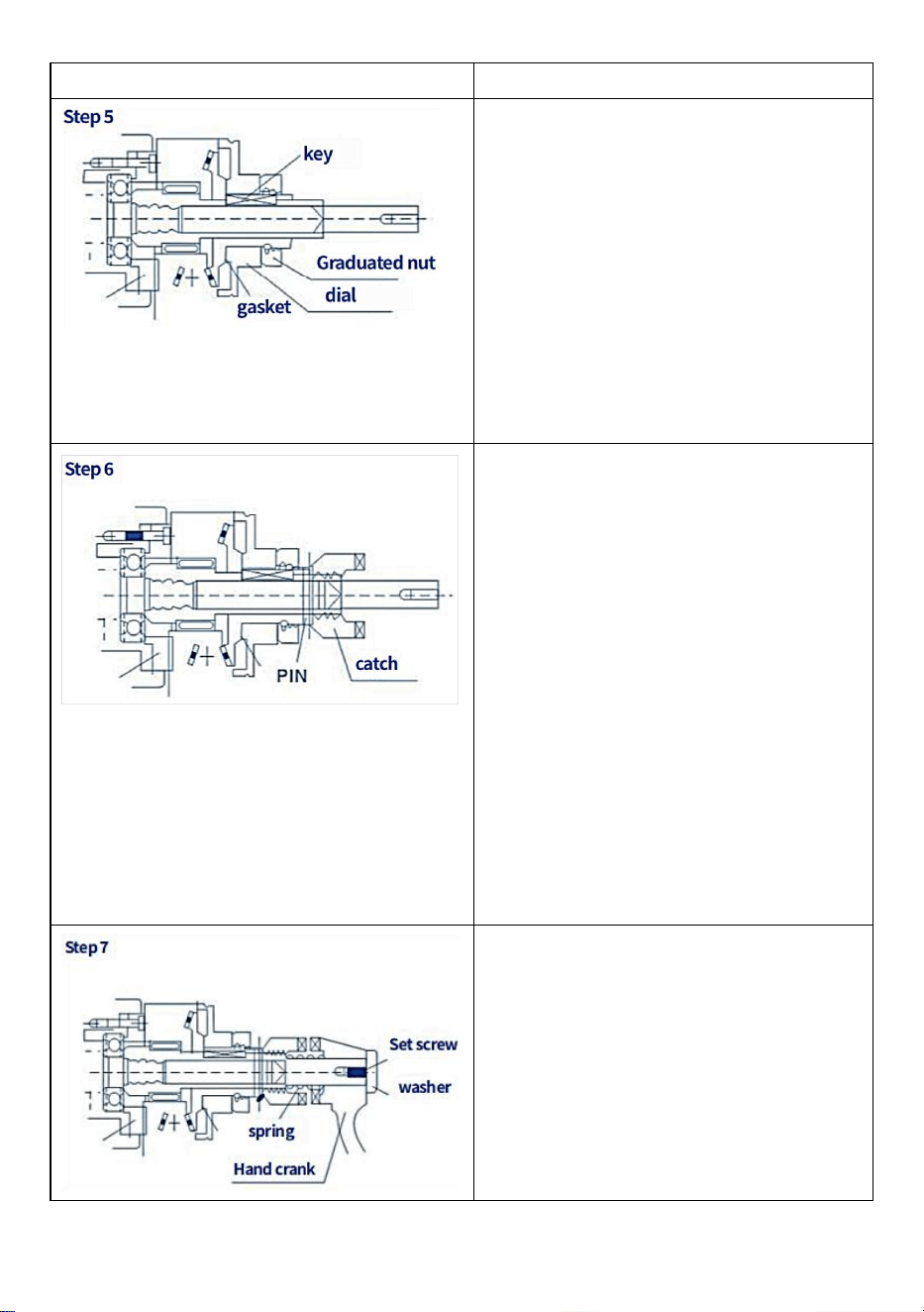
Step 5: Apply graphite base grease to the teeth of the bevel gear (004).
Apply a small amount of grease to the inner surface of the gear flange.
Step 6: Attach the bevel gear to the lead screw with the key and press
upward. Drive gear (061).Note: Usually, several spacers should be inserted
before installing the bevel gear (004). (005) in the inner ring(007) and the
bevel gear (004) to get the smallest possible clearance between the gear
assembly.The number of spacers (005) you will use is determined by your
test. Please refer to Figure 1:(005,004), etc
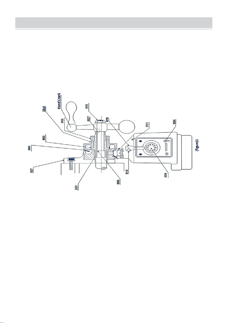
Step 7: Refer to Figure 1, install the appropriate dial on the bevel gear
(CLO04) and close to the power feed flange (do not touch each other!) .
Several spacers (CLO03) may then be required to meet the above
requirements.
Step 8: Screw the nut (002) into the bevel gear to prevent the dial from
loosening
Step 9: Reassemble the manual crank and remove it in step 1 onto the
lead screw. Then tighten the bevel gear (004), or use the lock nut (006) to
tighten it
- 5 -
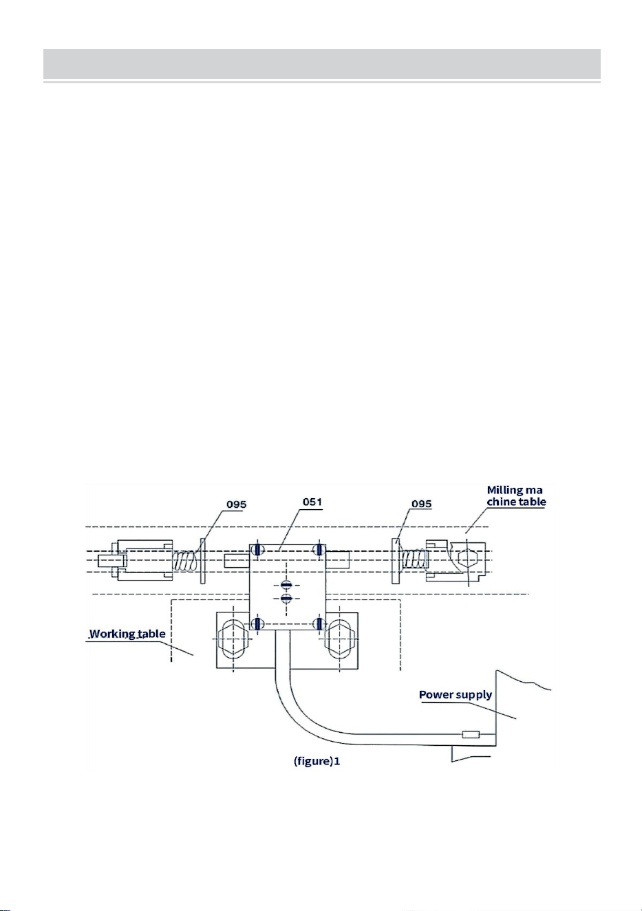
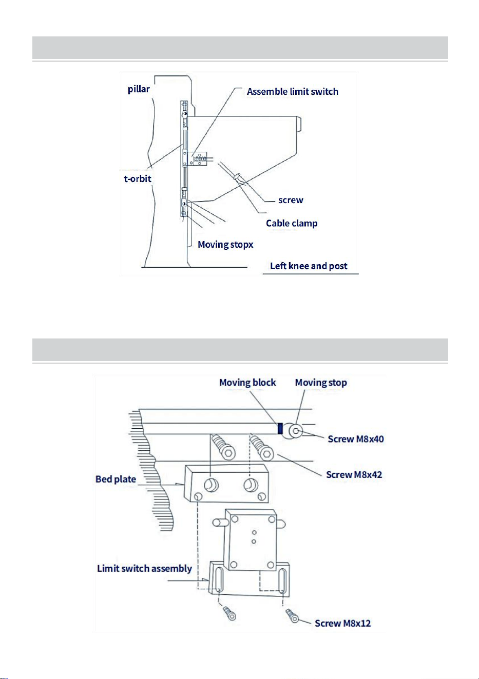
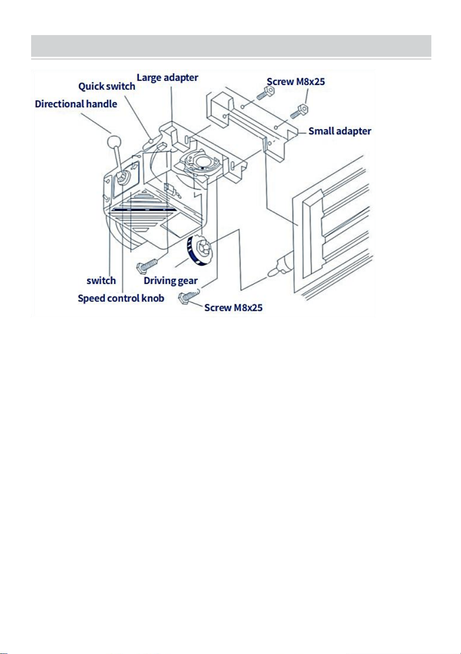
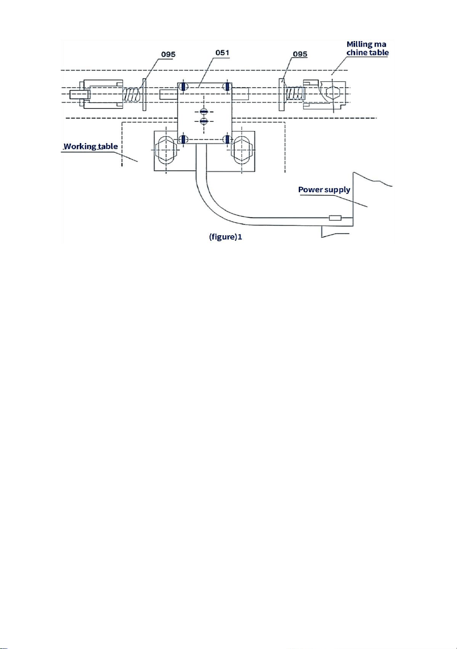
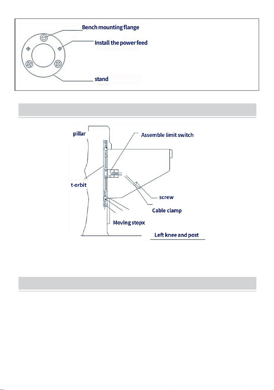
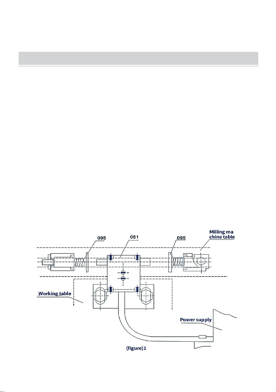
RESTRICTED ASSEMBLY INSTALLATION
The power feeder is equipped with a limit switch assembly (051) and a
transmission stop assembly (095). It is assembled as follows (please refer
to Figure 2):
Step 1: Remove the original travel limiter assembly from the workbench
and assemble the supplied travel limiter assembly (B18).
Step 2: Remove the original limit block and assemble the supplied limit
switch assembly (B05).
Pay attention
1. Make sure that the axial direction of the limit switch assembly (051) and
the two contact travel stop assembly (B18) of the rod should be on the
same axis.
2. Due to inertia, the installation distance of the travel stop assembly (095)
should be less than a few millimeters of travel
3. Protect the power cord of the limit switch. Don't let it get tangled up in
moving parts or tables.
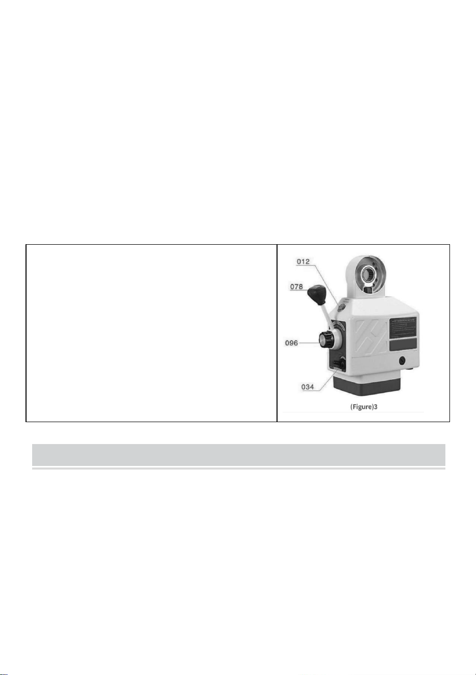
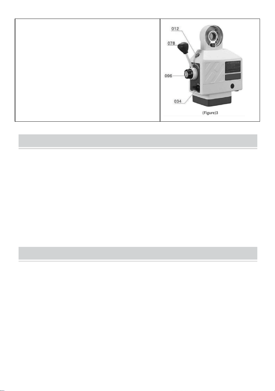
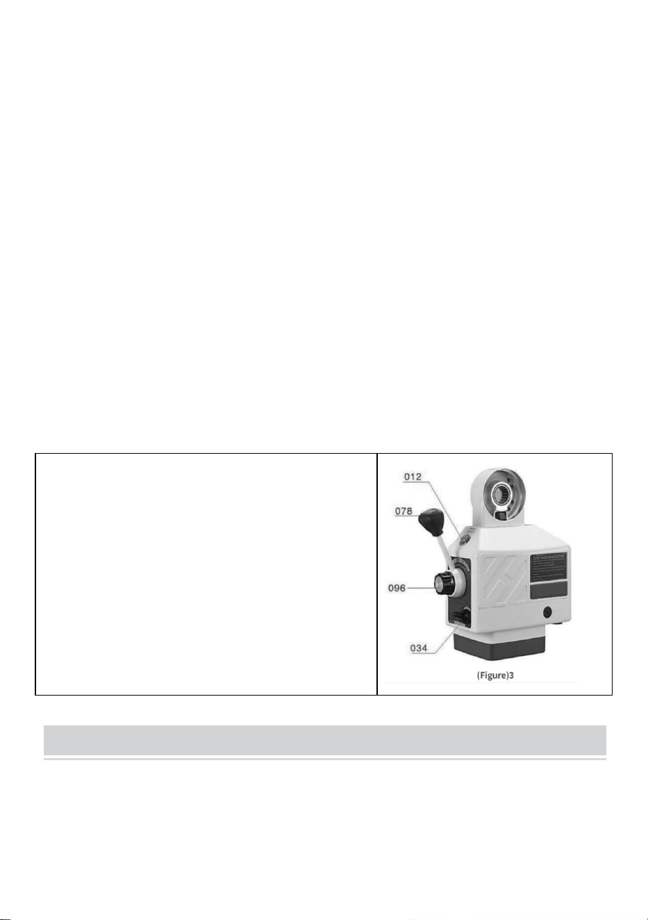
Operation of the power feeder is as follows (please refer to Figure 3):
Step 1: Ensure that the switch (034) is in the "Off" position and that the
control handle assembly (078) is in the Neutral (middle) position.
- 6 -
Step 2: Connect the power cable of the power station to the specific socket
Step 3: Turn the switch to the "ON" position, then the optical transmitter
(011) should light up
Step 4: Turn the control handle (078) from the middle position to one
direction, then the table will move in the same direction. Increase the
speed clockwise to control the knob assembly (096), and then adjust the
workbench to move at a speed that will gradually increase.
Step 5: If you want to change the direction of the table, turn the switch to
keep the handle in the middle position until the power is off. Then turn the
control lever in to the direction you want
(Make sure the power is off before changing direction)
NOTICE
1. The speed is controlled by the SPEED
CONTROL KNOB ASSY(B19).Position
“o”represents" stop" ang “g”represents the
highest speed.
2. RAPID SWITCH BUTTON (012)is for
fast movement of the table When it is
pressed, then the table will move at high
speed.
PERIODIC MAINTENANCE
1. Clean the machine every 250 hours, such as rotor direction change,
carbon accumulation and other dirt inside the machine, to ensure
insulation.
2. Lubrication, insert the lubricating oil into the gear and smear the grease
on the graphite base gear teeth
- 7 -
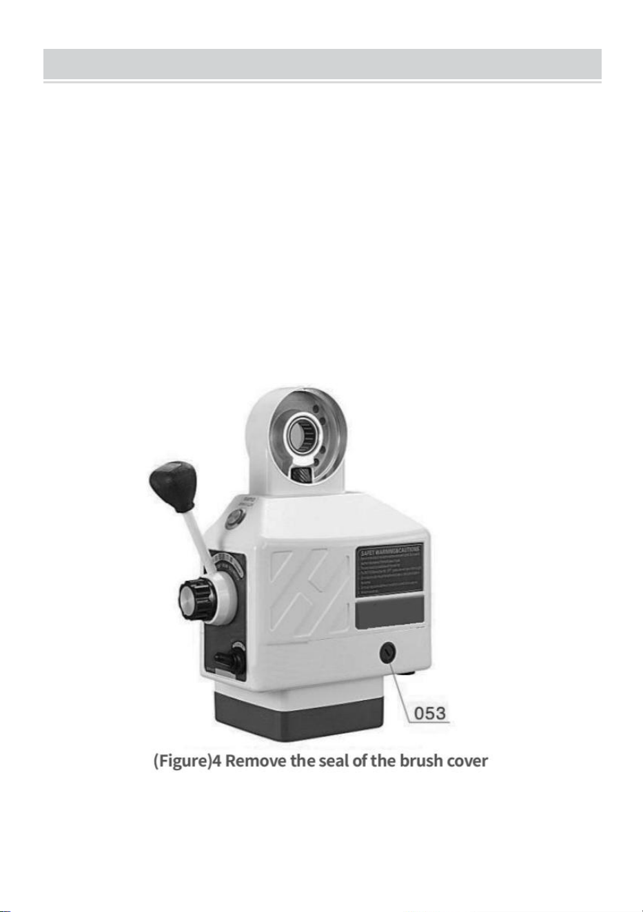
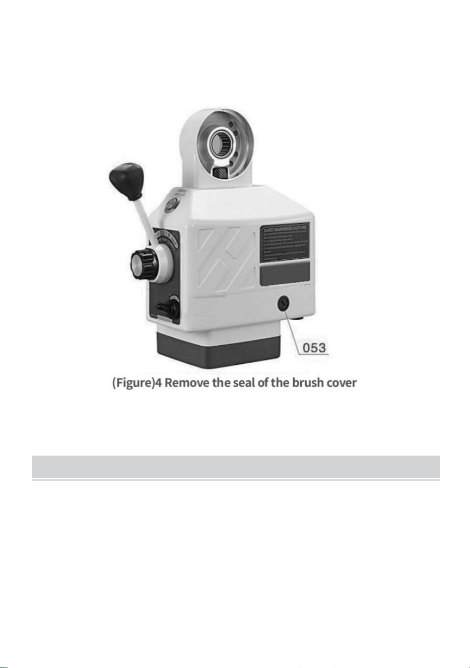
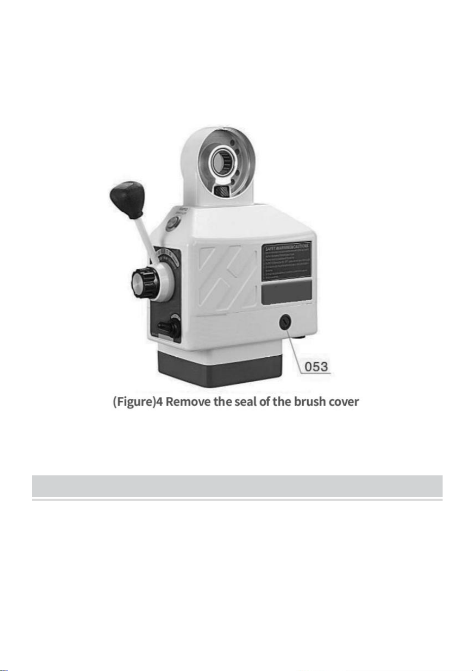
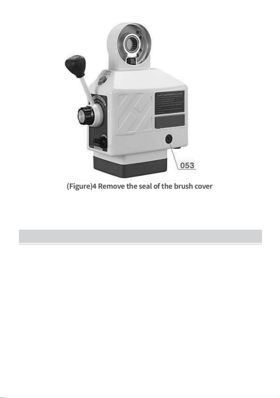
BRUSH POSITION
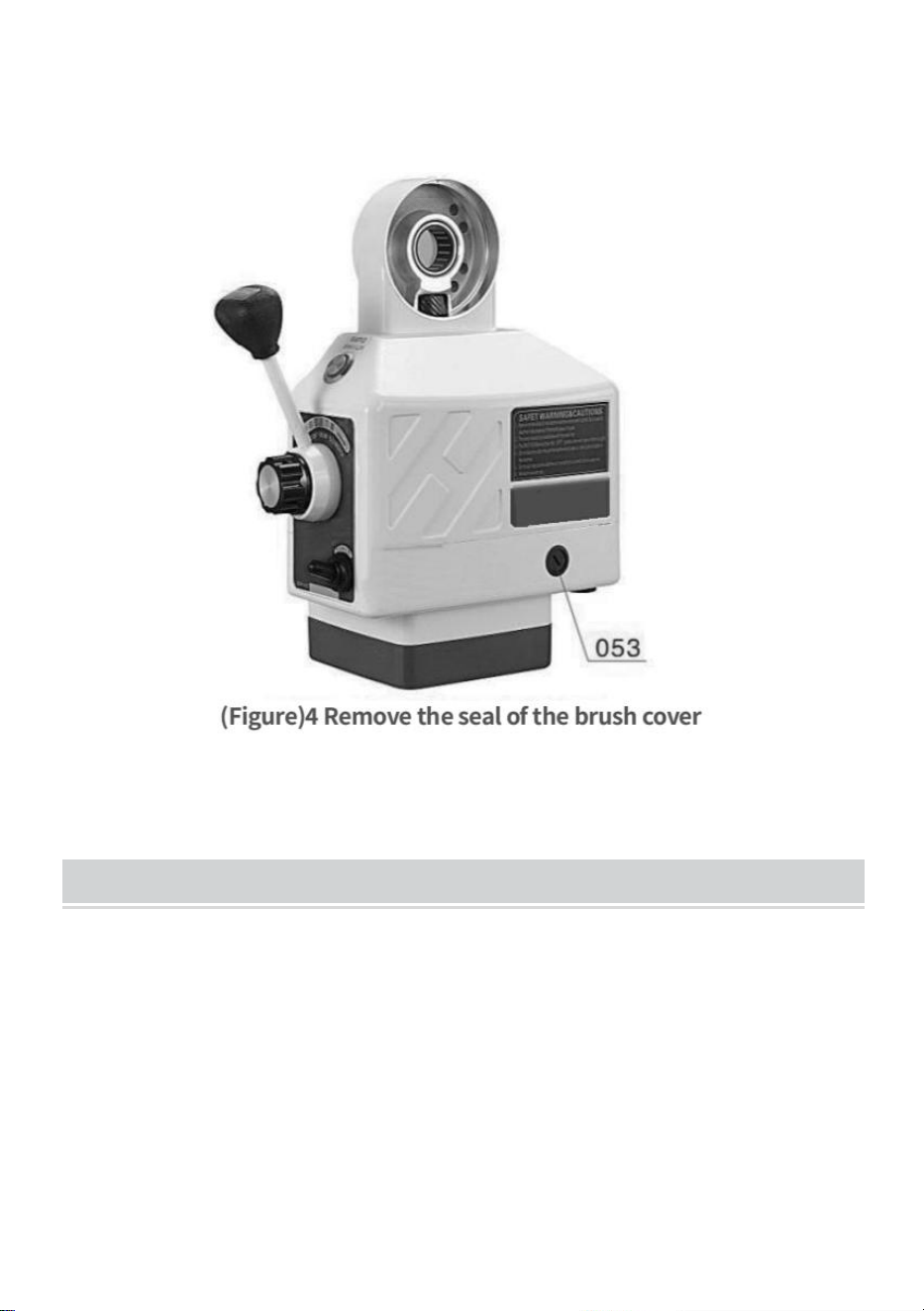
Step 1: Remove brush cap (053) (see Figure 4). Then the brush (050) may
pop up. Don't let go of the brush. If the brush does not pop, gently
remove it with the tip of a screwdriver.
Step 2: Check the concave of the brush. The surface should be smooth
and clean. If you notice large scratches on the brush, or if parts of the
brush have fallen off, or if the remaining length of the brush is only 6mm,
replace the brush immediately with an approved replacement brush. If it's
just a dirty brush, you can wipe the brush clean with a pencil and an eraser
to remove any lingering stains from the brush.
Step 3: The brush has a spring and brass plug. Turn the brass plug until the
prongs are vertical, then push the brush into the brush holder (052). Screw
the brush cap into the brush hole and tighten.
- 8 -
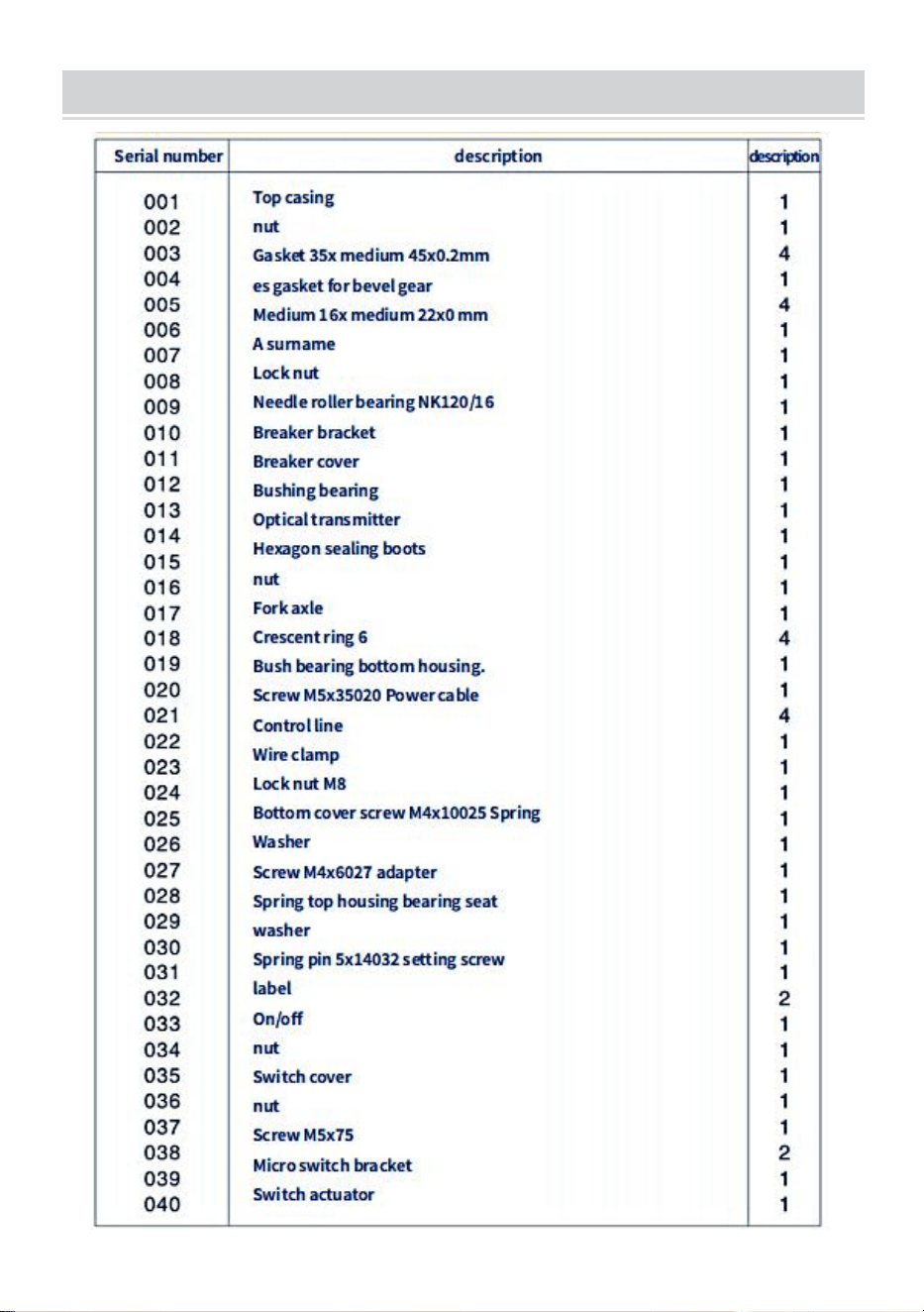
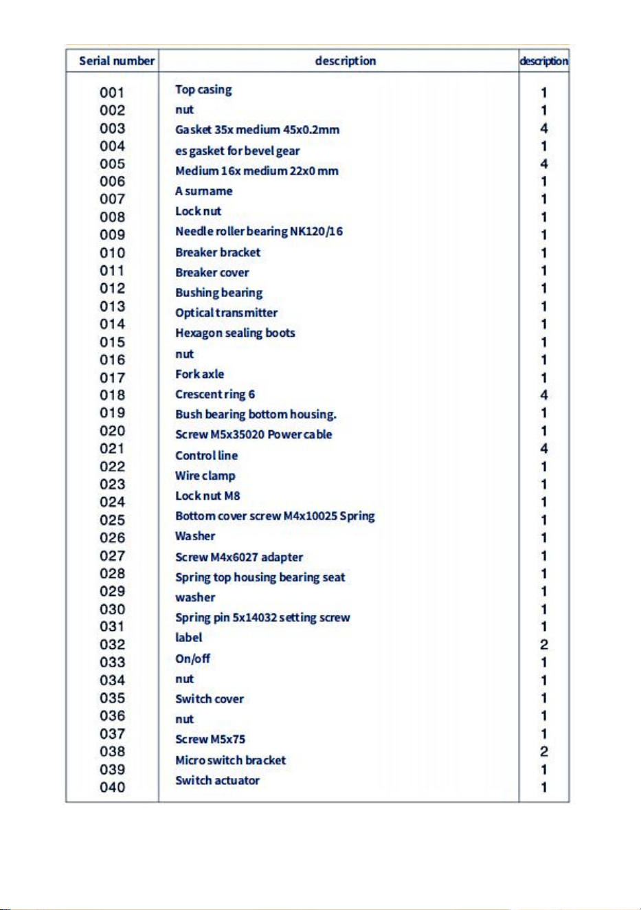
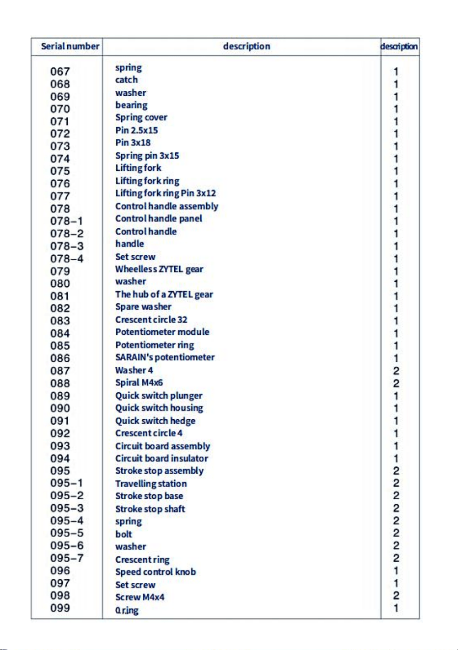
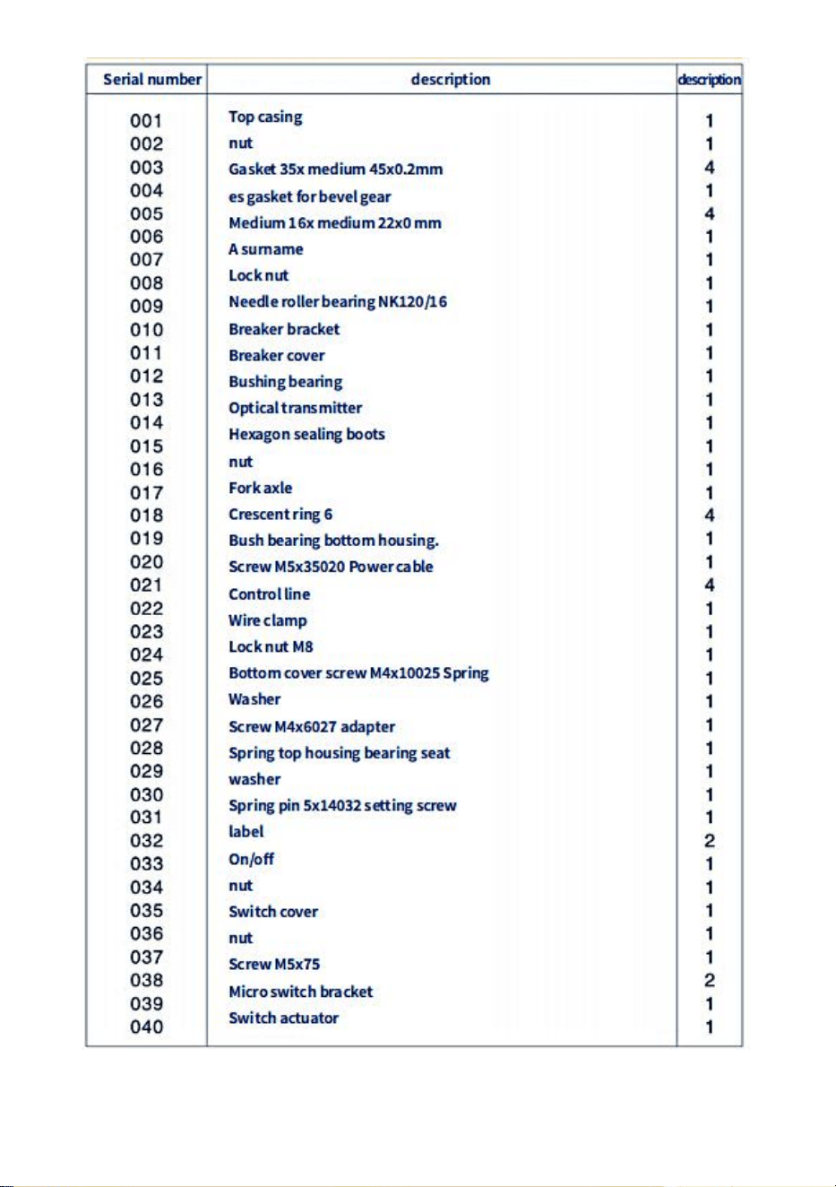
PARTS LIST

- 9 -

- 10 -

- 11 -

- 12 -
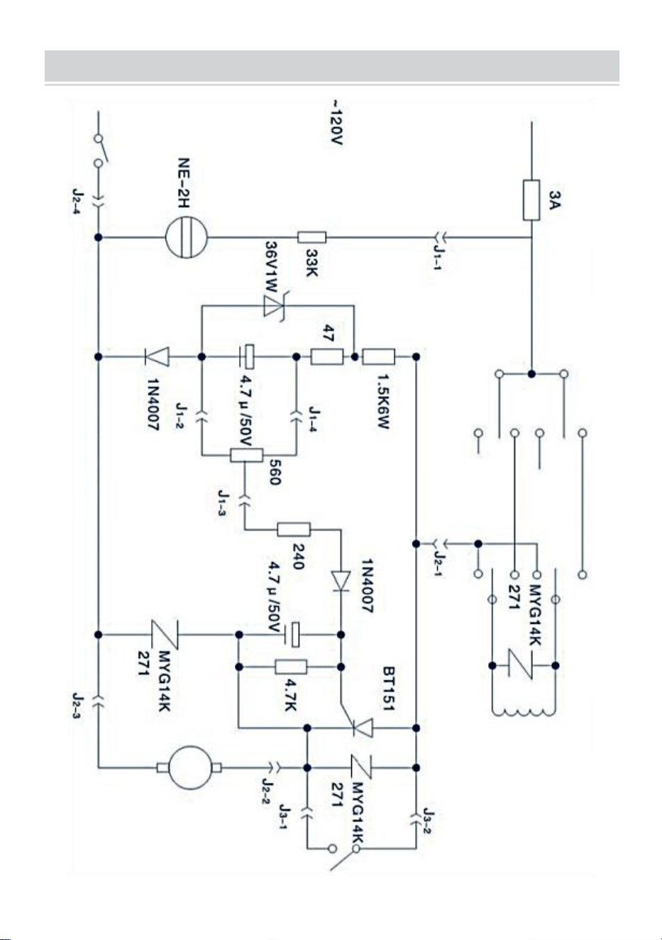
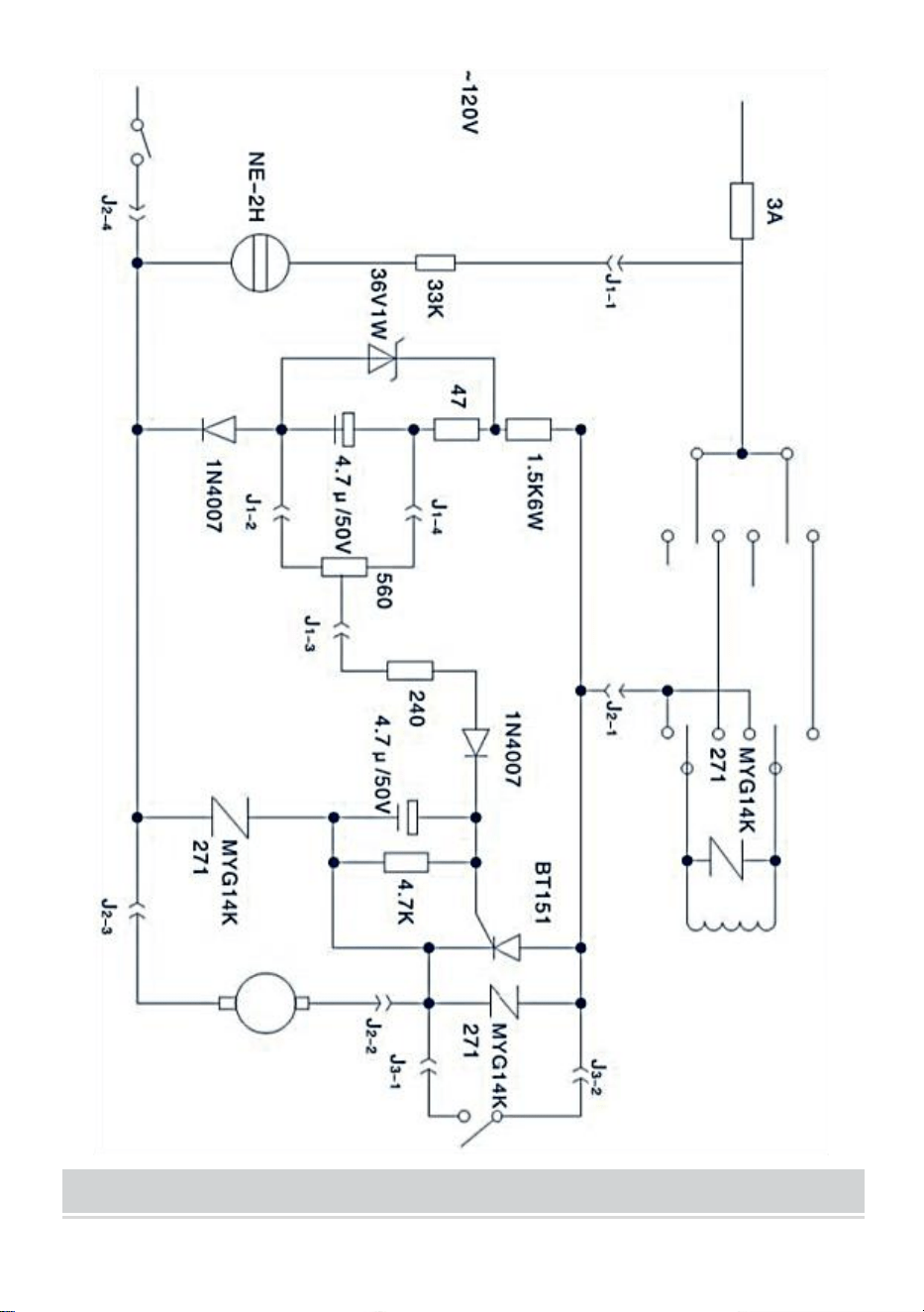
TROUBLESHOOTING
problem
Causes and solutions
The light emitter does
not emit light
1.The power supply or cable connection is faulty
2.The circuit breaker is damaged
3.Switch(034)is not in the"On"position or is
damaged.
4.If the motor can be moved,the optical transmitter
is damaged
The motor does not work
(078) left or right when the
control handle is pressed.
1.The motor rotates when the fast button (012)is
pressed
①the speed control knob is not in the "0"position
②Potentiometer(084)does notwork properly
③Circuit board (003)damaged
2.Press the fast button (012),the motor does not
rotate
①brush and rotor contact is bad or the brush is
used up.The circuit in
②is broken
description
1.There is a short circuit between the brush (050)
and the power feeder cover (017).Or a short circuit
exists in the limit switch (051)
2.The carbon powder in the carbon brush causes
short circuit.
Cannot get high speed fast
speed button when
pressed (012)
The micro switch (055)under the fast button (012)is
not connected
The motor does not work
(078)left or right when the
control handle is pressed
1.The fast button (012)does not work,and the micro
switch (055)is connected.
2.The controlled rectifier (BT141)on the resistance
(MYG14K)silicon circuit board is in the short circuit
state.
The table moved at an
unprecedented speed
The lead screw of this table is not good enough.
- 13 -
CIRCUIT DIAGRAM
- 14 -
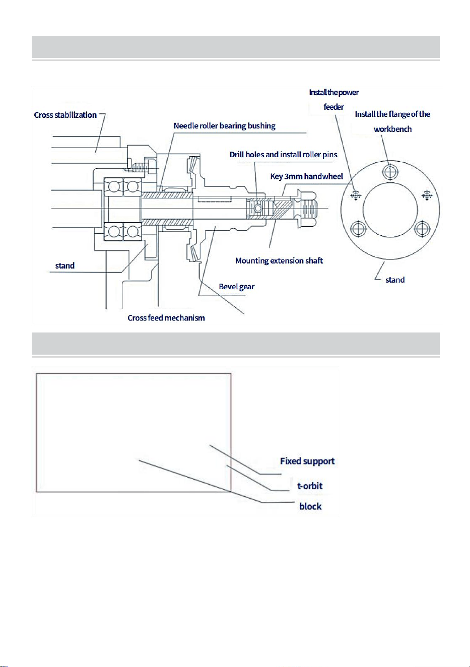
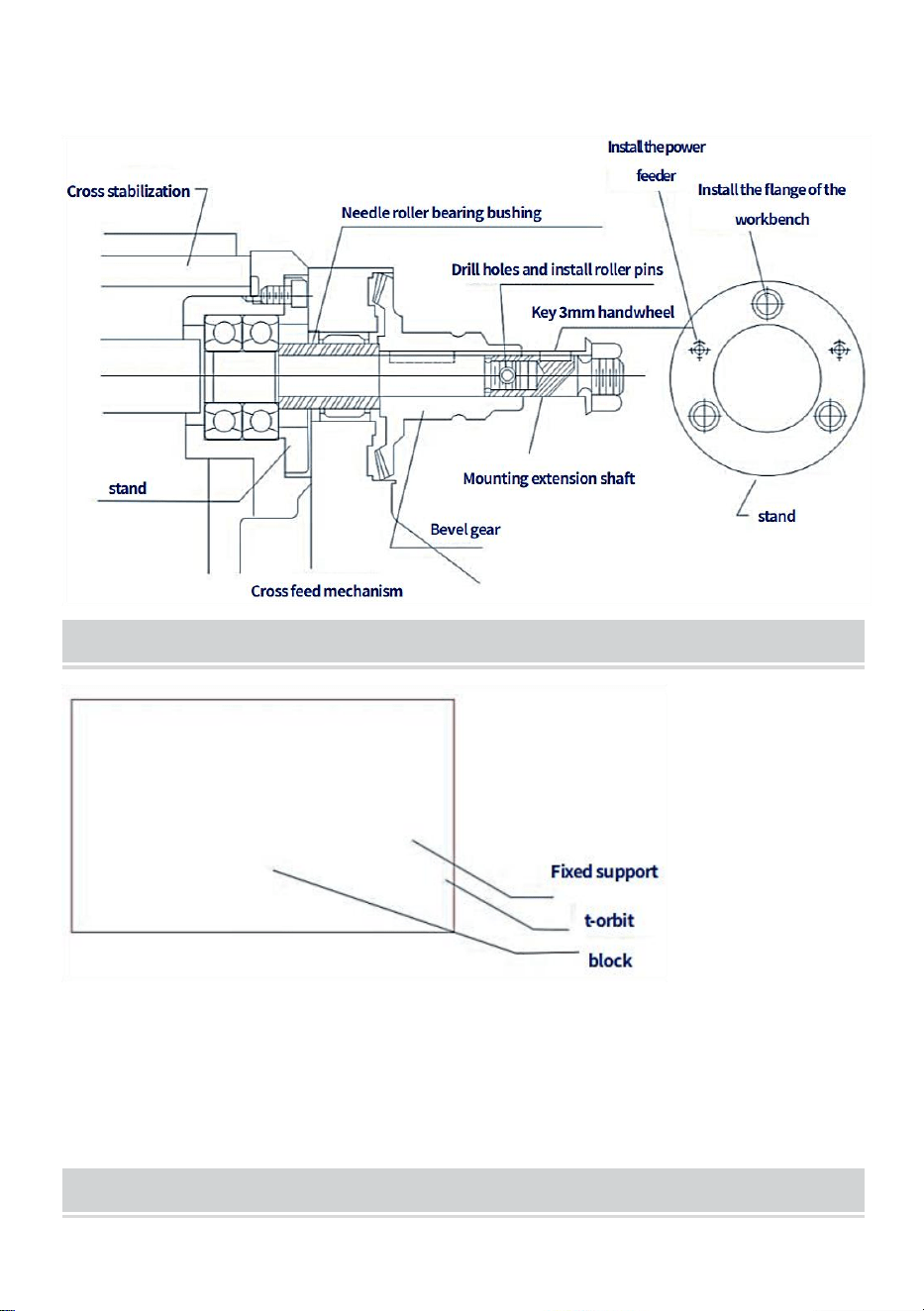
INSTRUCTIONS FOR INSTALLING CROSS FEEDS
Transverse stroke lead screws should not be modified for ideal installation
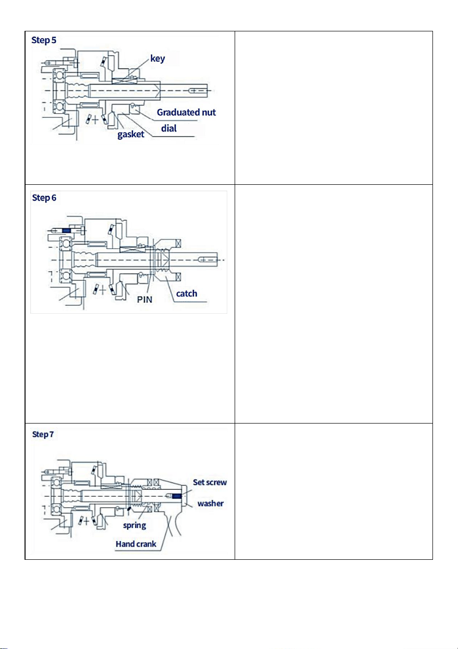
INSTALL T-SLOTS FOR TRANSVERSE FEED
- 15 -
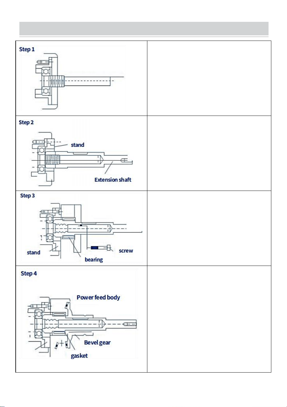
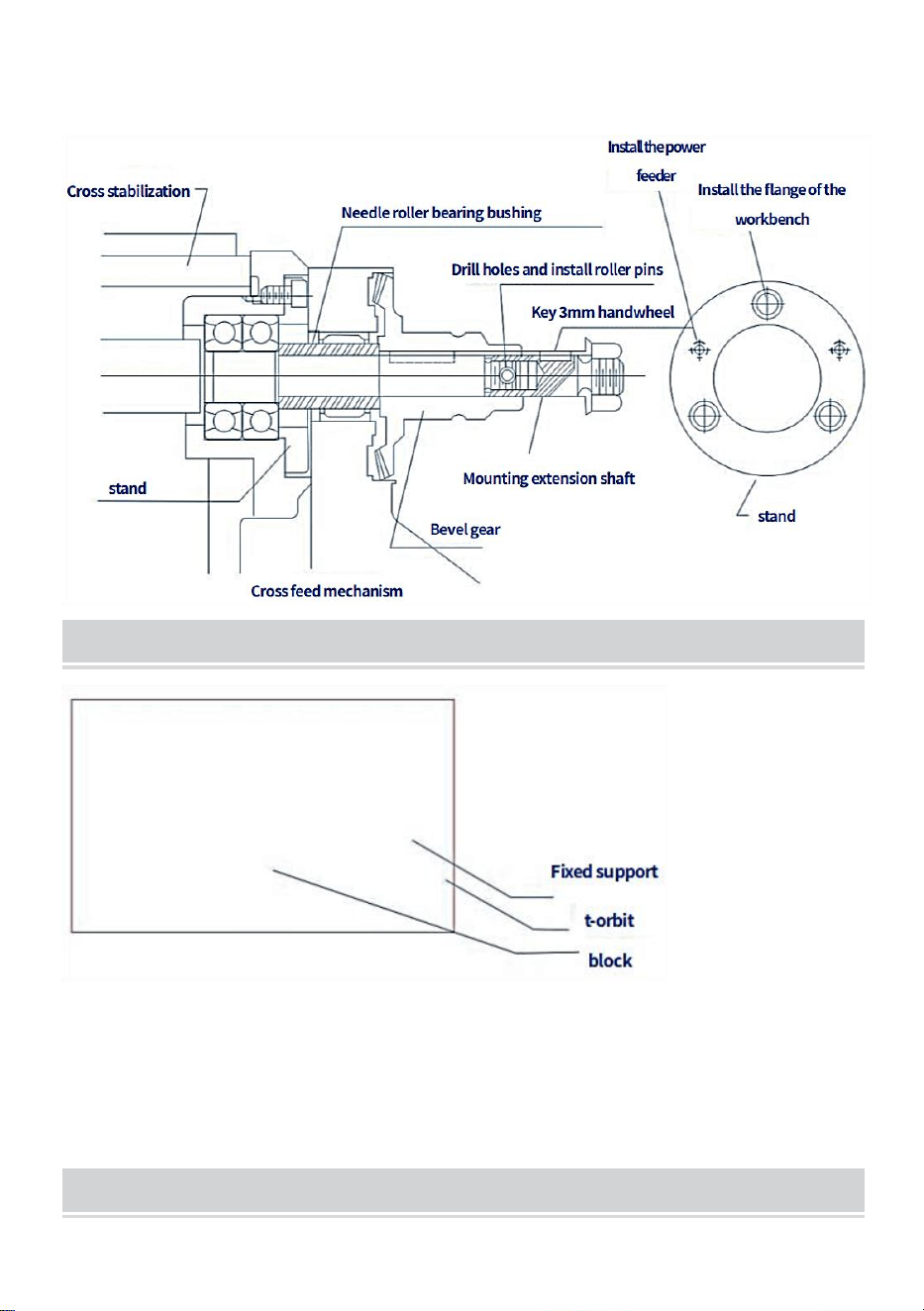
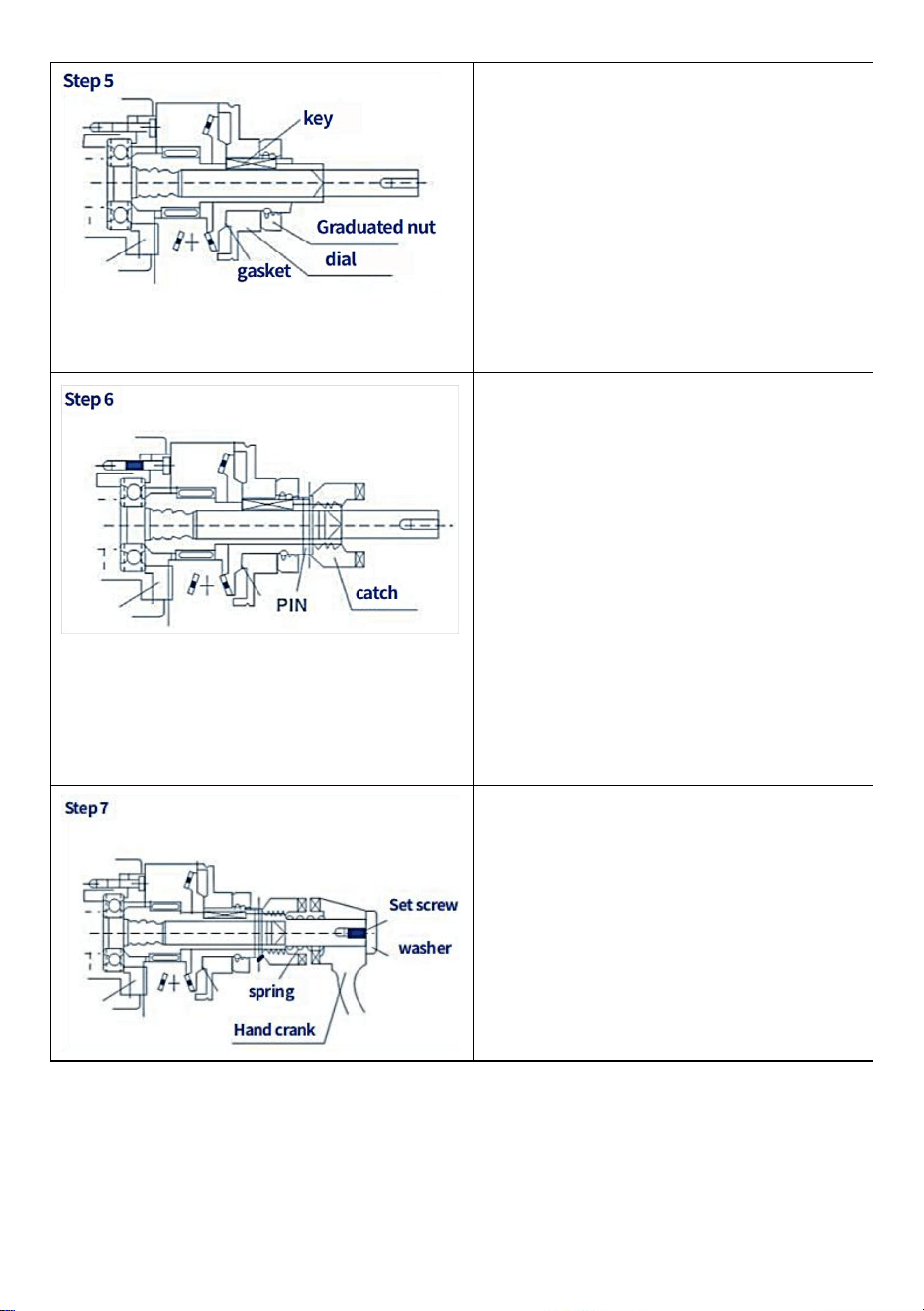
HOW TO INSTALL KNEE LIFT FEED
Remove the hand crank, dial, dial
bearing flange and ·.... · Etc.
Mounting extension shaft
Important Matters:
(1) The shaft end must be close to the
bearing inner ring
(2) The inner shaft is 16 or 18 thread
unc.
Tighten the support to the flange and
then tighten the knee rest on the
flange. Importantly, it is used for
angular positioning.
The safety gear key is not inserted
Push and turn the bevel gear by hand
to check the backlash.
(1) If necessary, add some spacers to
get proper backlash.
(2) Adjust the leading edge of the gear
to obtain proper rear clearance. Then
repack the gear with grease.
Reinstall the gear, then push and turn
to check the backlash
- 16 -
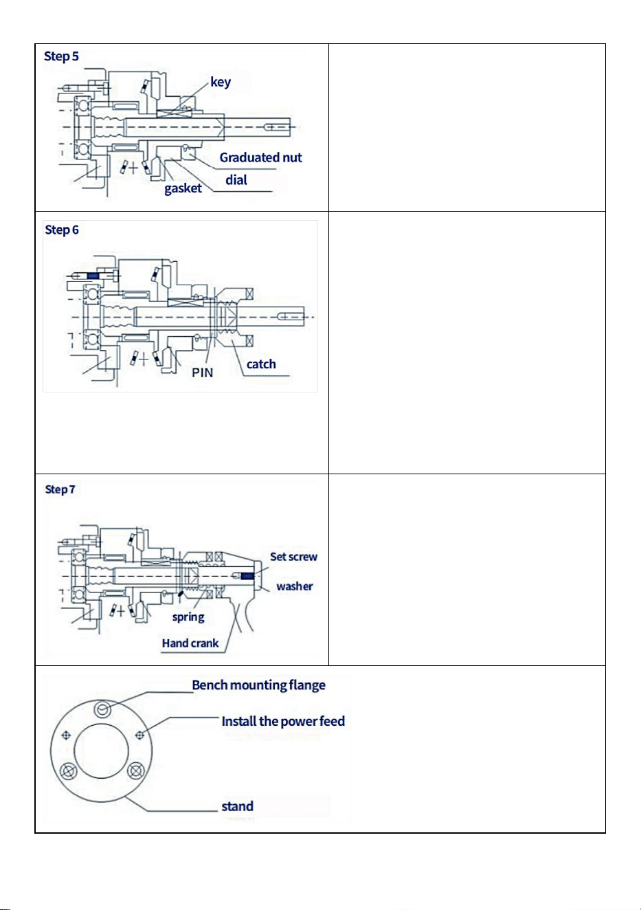
After step (4) is completed, remove
the bevel gear, then install the key,
replace the gear, install the dial,
tighten the dial nut (add a few small
pieces of dial grinding gear). Pack the
gear with grease before installing it (do
not use silicone grease).
Install the check rod on the bevel gear
and drill it into the 5mm diameter hole.
Then drive the spring pin.
One important note: Before installing
the spring pin, make sure you have
carefully and correctly performed each
step. It is recommended to install a
manual crank and turn it clockwise to
check whether the potential sheet is
correct and whether there is stuck
action.
Install the spring crank (already
installed) then tighten the washer and
screws. It is important to lubricate this
part and follow the instructions for safe
operation.
- 17 -
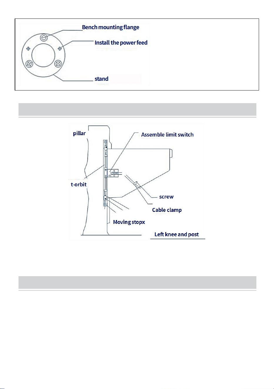
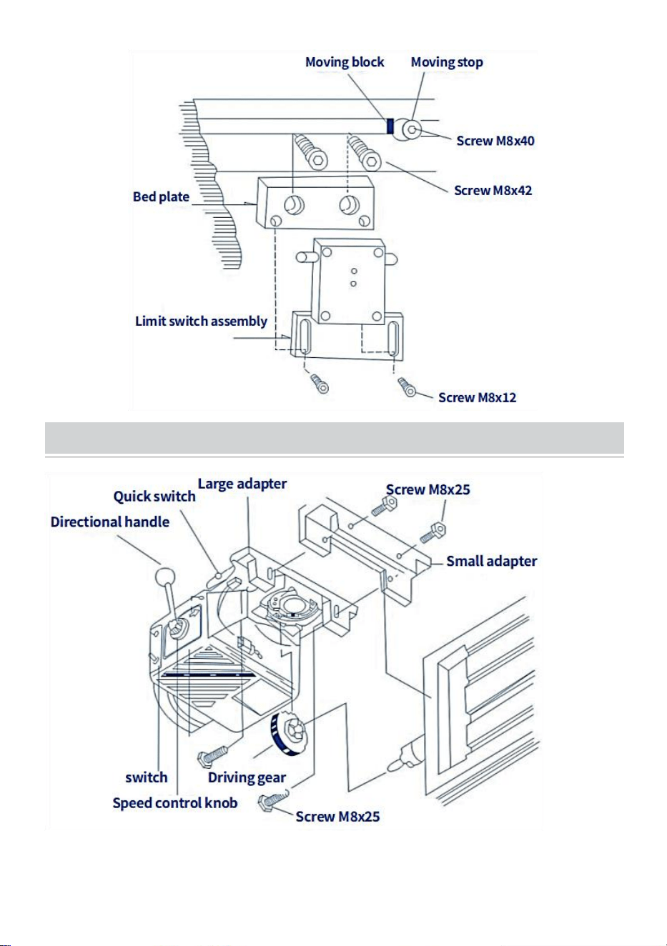
INSTALL T - RAIL LIFT FEED
ASSEMBLY - LIMIT ASSEMBLY INSTRUCTIONS
- 18 -
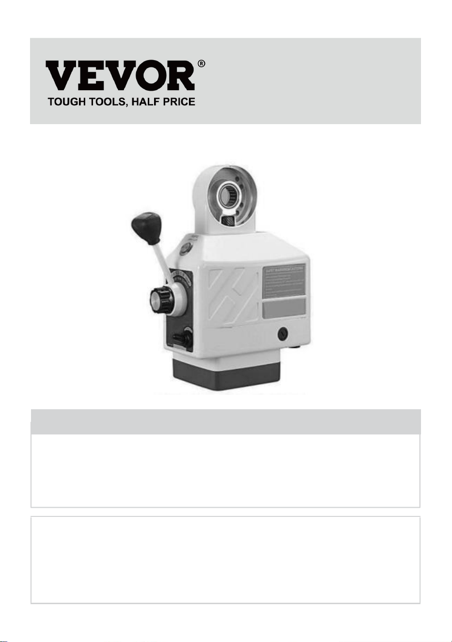
LONGITUDINAL FEED - HORIZONTAL ARRANGEMENT
assembly
1. Move the catwalk to the far left
2. Remove the hand crank, dial and bearing flange from the runway.
3. If necessary, install extension shaft for T-table and assemble drive
gear.
4. Remove the two screws (M8 x 25) from the small adapter.
5. Horizontally install the power feeder on the large adapter.
6. Adjust the position and clearance of gears
7. Tighten the screws on the drive gear.
8. Tighten the two screws of the small adapter (2-M8x25)
9. Put some graphite grease on the teeth of the transmission gear
Sanven Technology Ltd.
Address: Suite 250, 9166 Anaheim Place, Rancho Cucamonga, CA
91730
Made In China


- 2 -
Technique Assistance et certificat de garantie électronique
www.vevor.com/support
ALIMENTATION DE LA TABLE DE
PUISSANCE DU BROYEUR
MODÈLE: AL-450
We continue to be committed to provide you tools with competitive price.
"Save Half", "Half Price" or any other similar expressions used by us only represents an
estimate of savings you might benefit from buying certain tools with us compared to the major
top brands and does not necessarily mean to cover all categories of tools offered by us. You
are kindly reminded to verify carefully when you are placing an order with us if you are
actually saving half in comparison with the top major brands.

- 3 -

- 1 -
MODÈLE: AL-450
Have product questions? Need technical support? Please feel free to
contact us:
Technical Support and E-Warranty Certificate
www.vevor.com/support
NEED HELP? CONTACT US!
This is the original instruction, please read all manual instructions
carefully before operating. VEVOR reserves a clear interpretation of our
user manual. The appearance of the product shall be subject to the
product you received. Please forgive us that we won't inform you again if
there are any technology or software updates on our product.
MILL POWER TABLE FEED

- 2 -
BRIEF INTRODUCTION
Bienvenue à utiliser cette alimentation. Cela rendra votre travail pratique et
vous rendra heureux. Veuillez lire attentivement ce manuel pour
l'assemblage et l'utilisation de cette machine.
Convient à tous les alimentateurs de fraiseuses à tourelle verticales, y
compris, mais sans s'y limiter, Bridgeport, précision Matthews, grizzly,
enco, jet, sharp, Webb, GMC, Clark, supermax, turn pro, vectrax, acra,
Birmingham, accu, first et plus, si vous fraisez avec le même mode
d'installation et un arbre de 5/8" de diamètre à La fin.Tant qu'il s'agit d'une
machine de type Bridgeport, elle devrait convenir. (elle ne conviendra pas
aux fraiseuses avec différents modes d'installation ou aux vis mères de
différentes tailles, telles que Powermatic et certaines autres machines de
taille étrange, alors s'il vous plaît assurez-vous que votre machine est du
type Bridgeport typique ci-dessus)
SAFETY WARNINGS AND PRECAUTIONS
1. Gardez la zone de travail propre. N'utilisez pas cette machine dans des
endroits humides. N'utilisez pas cette machine dans le présence de gaz ou
de liquides inflammables.
2. L'alimentation électrique doit être adaptée à l'alimentation.
3. L'interrupteur (034) doit être en position « off » avant de ne pas être
utilisé ou inséré.
4. Ne mettez rien d'autre sur la machine. Évitez de renverser de l'eau ou
d'autres liquides sur la machine
5. Ne faites pas essayez de dépasser la capacité de l'outil en utilisant des
accessoires inappropriés.
6. Entretenez soigneusement les outils.

- 3 -
SPECIFICATIONS
Modèle
Vitess
e
Maximum
Retour Vitesse
Maximum
couple
Tension
AL-260
0~ 20
0
2 77 tr/min
1385 mm/min
(passage de vis
externe 5 mm)
450
pouces-livr
e
110 V (220
V-240 V) 50/60
Hz
AL-310
0~ 20
0
2 77 tr/min
1385 mm/min
(passage de vis
externe 5 mm)
450
pouces-livr
e
110 V (220
V-240 V) 50/60
Hz
AL-450
0~ 20
0
2 77 tr/min
1385 mm/min
(passage de vis
externe 5 mm)
450
pouces-livr
e
110 V (220
V-240 V) 50/60
Hz
OPEN THE BOX
Description du projet
Quantité
Joint d'engrenage en cuivre
1
Installer la plaque de retenue
1
Clé plate
1
Cale de réglage
15
Boîtier étanche pour interrupteur de fin
de course
1
Ressort de fin de course
2
Bloc limite
2
Vis de fixation
4
Engrenage en cuivre
1
Arbre allongé
1
Ressort d'arbre allongé
1
DRIVE INSTALLATION
Étape 1 : retirez la manivelle, le cadran et la bride de roulement du côté
- 4 -
droit de la table.
Étape 2 : Installez le chargeur de puissance avec l'adaptateur (027) dans
la position de la bride de roulement. Assemblez l'adaptateur au bout de la
table à l'aide de quatre écrous hexagonaux. La vis, qui doit être complété
par l'étape 3, garantit la position correcte de la vis mère
Étape 3 : Faites glisser la bague intérieure (007) sur la vis mère de le banc,
puis glissez-le dans le trou de le roulement à aiguilles d'alimentation
électrique. Enfin, l'anneau intérieur doit toucher l'épaule de la laisse.
écranVeuillez revenir à la figure 1 (027007)
Étape 4 : Insérez la clé dans la rainure de la vis mère
Étape 5 : Appliquez de la graisse à base de graphite sur les dents de
l'engrenage conique (004). Appliquez une petite quantité de graisse sur la
surface intérieure de l'engrenage bride .
Étape 6 : Fixez l'engrenage conique à la vis mère avec la clé et appuyez
vers le haut. Pignon d'entraînement (061).Remarque : Généralement,
plusieurs entretoises doivent être insérées avant d'installer le pignon
conique (004). (005) dans le bague intérieure (007) et l'engrenage conique
(004) pour obtenir le plus petit jeu possible entre le ensemble
d'engrenages. Le nombre d'entretoises (005) que vous utiliserez est
déterminé par votre test. Veuillez vous référer à la figure 1 :(005,004), etc.
Étape 7 : Reportez-vous à la figure 1, installez le cadran approprié sur
l'engrenage conique (CLO04) et à proximité du bride d'alimentation

- 5 -
électrique (ne pas se toucher !) . Plusieurs entretoises (CLO03) peuvent
alors être nécessaires rencontrer les exigences ci-dessus.
Étape 8 : Vissez l'écrou (002) dans l'engrenage conique pour éviter que le
cadran ne se desserre
Étape 9 : Réassemblez le rang c manuel et retirez-le à l'étape 1 sur la vis
mère. Puis serrez le biseau engrenage (004), ou utilisez le contre-écrou
(006) pour le serrer.
RESTRICTED ASSEMBLY INSTALLATION
L'alimentation électrique est équipée d'un ensemble interrupteur de fin de
course (051) et d'un ensemble d'arrêt de transmission (095). Il est
assemblé comme suit (veuillez vous référer à la figure 2) :
Étape 1 : Retirez l'ensemble limiteur de course d'origine de l'établi et
assemblez l'ensemble limiteur de course fourni (B18).
Étape 2 : Retirez le bloc de fin de course d'origine et assemblez l'ensemble
de commutateur de fin de course fourni (B05).
Faites attention
1. Assurez-vous que la direction axiale de l'ensemble de fin de course (051)
et de l'ensemble de butée de course à deux contacts (B18) de la tige doit
être sur le même axe.
2. En raison de l'inertie, la distance d'installation de l'ensemble de butée de
course (095) doit être inférieure à un quelques millimètres de déplacement
3. Protégez le cordon d'alimentation du fin de course. Ne le laissez pas
s'emmêler dans les pièces mobiles ou les tables.
- 6 -
Le fonctionnement de l'alimentation électrique est le suivant (veuillez vous
référer à la figure 3) :
Étape 1 : Assurez-vous que l'interrupteur (034) est en position « OFF » et
que l'ensemble de poignée de commande (078) est en position neutre
(milieu).
Étape 2 : Connectez le câble d'alimentation de la centrale à la prise
spécifique
Étape 3 : Tournez l'interrupteur sur la position "ON", puis l'émetteur optique
(011) devrait s'allumer
Étape 4 : Tournez la poignée de commande (078) de la position centrale
vers une direction, la table se déplacera alors dans la même direction.
Augmentez la vitesse dans le sens des aiguilles d'une montre pour
contrôler l'ensemble de boutons (096), puis ajustez l'établi pour qu'il se
déplace à une vitesse qui augmentera progressivement.
Étape 5 : Si vous souhaitez changer la direction de la table, tournez
l'interrupteur pour maintenir la poignée en position médiane jusqu'à ce que
l'alimentation soit coupée. Tournez ensuite le levier de commande dans la
direction souhaitée
(Assurez-vous que l'alimentation est coupée avant de changer de
direction)

- 7 -
AVIS
1 . La vitesse est contrôlée par le SPEED
CONTRÔLE KNOB ASSY (B19). La
position "o" représente "stop" ang « g »
représente la vitesse la plus élevée.
3. LE BOUTON DE COMMUTATION
RAPIDE (012) est destiné mouvement
rapide de la table Lorsqu'on appuie
dessus, alors la table se déplacera à
grande vitesse.
PERIODIC MAINTENANCE
3. Nettoyez la machine toutes les 250 heures, comme le changement de
direction du rotor, l'accumulation de carbone et autres saleté à l'intérieur de
la machine, pour assurer l'isolation.
4. Lubrification, insérez l'huile lubrifiante dans l'engrenage et étalez la
graisse sur l'engrenage à base de graphite dents
BRUSH POSITION
Étape 1 : Retirez le capuchon de la brosse (053) (voir Figure 4). Ensuite, le
pinceau (050) peut apparaître. Ne lâchez pas le pinceau. Si la brosse ne
saute pas, retirez-la délicatement avec la pointe d'un tournevis.
Étape 2 : Vérifiez le concave de la brosse. La surface doit être lisse et
propre. Si vous remarquez de grandes rayures sur la brosse, ou si des
parties de la brosse sont tombées, ou si la longueur restante de la brosse
n'est que de 6 mm, remplacez immédiatement la brosse par une brosse de
remplacement approuvée. S'il ne s'agit que d'un pinceau sale, vous
pouvez l'essuyer avec un crayon et une gomme pour éliminer les taches
persistantes du pinceau.
- 8 -
Étape 3 : La brosse est dotée d'un ressort et d'un bouchon en laiton.
Tournez le bouchon en laiton jusqu'à ce que les broches soient verticales,
puis poussez la brosse dans le porte-balai (052). Vissez le capuchon de la
brosse dans le trou de la brosse et serrez.
PARTS LIST

- 9 -

- 10 -

- 11 -

- 12 -

- 13 -
TROUBLESHOOTING
problème _ _
Causes et solutions
L'émetteur de lumière fait
pas émettre de la lumière
1.Le pouvoir l'alimentation ou la connexion du câble
est défectueuse
2.Le disjoncteur est endommagé
3. L'interrupteur (034) n'est pas en position « On »
ou est
endommagé.
4. Si le moteur peut être déplacé, l'émetteur optique
est endommagé
Le moteur ne fonctionne
pas
(078) à gauche ou à droite
quand la poignée de
commande est pressé .
1. Le moteur tourne lorsque le bouton rapide (012)
est enfoncé
①le bouton de contrôle de vitesse n'est pas dans la
position "0"
②Le potentiomètre (084) ne fonctionne pas
correctement
③Circuit imprimé (003) endommagé
2. Appuyez sur le bouton rapide (012), le moteur ne
tourne pas
①brosse et rotor le contact est mauvais ou la
brosse est épuisée. circuit dans
②est cassé
description
1. Il y a un court-circuit entre la brosse (050) et le
couvercle de l'alimentation électrique (017).Ou un
court-circuit existe dans l'interrupteur de fin de
course (051)
2.La poudre de carbone dans le balai de charbon
provoque court-circuit.
Impossible d'obtenir une
vitesse élevée bouton de
vitesse rapide lorsque
pressé (012)
Le micro-interrupteur (055) sous le bouton rapide
(012) n'est pas connecté
Le moteur ne fonctionne
pas (078)gauche ou droite
quand la poignée de
commande est pressé
1. Le bouton rapide (012) ne fonctionne pas et le
micro l'interrupteur (055) est connecté.
2. Le redresseur contrôlé (BT141) sur le résistance
(MYG14K) le circuit imprimé en silicium est en
court-circuit
État.

- 14 -
La table bougeait à un
rythme vitesse sans
précédent
La vis mère de cette table n'est pas assez bonne.
CIRCUIT DIAGRAM

- 15 -
INSTRUCTIONS FOR INSTALLING CROSS FEEDS
- 16 -
Les vis mères à course transversale ne doivent pas être modifiées pour une
installation idéale
INSTALL T-SLOTS FOR TRANSVERSE FEED
HOW TO INSTALL KNEE LIFT FEED

- 17 -
Retirer la manivelle, le cadran, la bride
de roulement du cadran et ·.... · Etc.
Arbre d'extension de montage
Questions importantes :
(1) L'extrémité de l'arbre doit être
proche de la bague intérieure du
roulement
(2) L'arbre intérieur est à 16 ou 18
filetages unc.
Serrez le support sur la bride puis
serrez la genouillère sur la bride.
Surtout, il est utilisé pour le
positionnement angulaire.
La clé du parachute n’est pas insérée
Poussez et tournez l'engrenage
conique à la main pour vérifier le jeu.
(1) Si nécessaire, ajoutez quelques
entretoises pour obtenir une bonne
contrecoup.
(2) Ajustez le bord d'attaque de
l'engrenage pour obtenir un jeu arrière
approprié. Remplissez ensuite
l'engrenage avec de la graisse.
Réinstallez l'engrenage, puis poussez
et tournez pour vérifier le jeu
- 18 -
Une fois l'étape ( 4 ) terminée, retirez
l'engrenage conique, puis installez la
clé, remplacez l'engrenage, installez le
cadran, serrez l'écrou du cadran
(ajoutez quelques petits morceaux
d'engrenage de meulage du cadran).
Garnissez l'engrenage de graisse
avant de l'installer (n'utilisez pas de
graisse silicone).
Installez la tige de contrôle sur
l'engrenage conique et percez-la dans
le trou de 5 mm de diamètre. Ensuite,
enfoncez la goupille élastique.
Un important Remarque : Avant
d'installer la goupille élastique,
assurez-vous d'avoir effectué
soigneusement et correctement
chaque étape. Il est recommandé
d'installer une manivelle manuelle et
de la tourner dans le sens des
aiguilles d'une montre pour vérifier si
la feuille de potentiel est correcte et s'il
y a une action bloquée.
Installez la manivelle à ressort (déjà
installée) puis serrez la rondelle et les
vis . Il est important de lubrifier cette
pièce et de suivre les instructions pour
un fonctionnement en toute sécurité.

- 19 -
INSTALL T - RAIL LIFT FEED
ASSEMBLY - LIMIT ASSEMBLY INSTRUCTIONS

- 20 -
LONGITUDINAL FEED - HORIZONTAL ARRANGEMENT
assemblée
1 . Déplacez le podium à l'extrême gauche

- 21 -
2. Retirez la manivelle, le cadran et la bride de roulement de la piste.
3. Si nécessaire, installez l'arbre d'extension pour la table en T et
assemblez l'entraînement.
engrenage.
4. Retirez les deux vis (M8 x 25) du petit adaptateur.
5. Installez horizontalement le chargeur d'alimentation sur le grand
adaptateur.
6. Ajustez la position et le jeu des engrenages
7. Serrez les vis sur le pignon d'entraînement.
8. Serrez les deux vis du petit adaptateur (2-M8x25)
9. Mettez un peu de graisse graphite sur les dents du pignon de
transmission
Sanven Technologie Ltd.
Adresse : Suite 250, 9166 Anaheim Place, Rancho Cucamonga, CA
91730
Fabriqué en Chine


- 2 -
Technisch Support- und E-Garantiezertifikat
www.vevor.com/support
MÜHLEN-POWER-TISCHVORSCHUB
MODELL: AL-450
We continue to be committed to provide you tools with competitive price.
"Save Half", "Half Price" or any other similar expressions used by us only represents an
estimate of savings you might benefit from buying certain tools with us compared to the major
top brands and does not necessarily mean to cover all categories of tools offered by us. You
are kindly reminded to verify carefully when you are placing an order with us if you are
actually saving half in comparison with the top major brands.

- 1 -
MODELL: AL-450
Have product questions? Need technical support? Please feel free to
contact us:
Technical Support and E-Warranty Certificate
www.vevor.com/support
NEED HELP? CONTACT US!
This is the original instruction, please read all manual instructions
carefully before operating. VEVOR reserves a clear interpretation of our
user manual. The appearance of the product shall be subject to the
product you received. Please forgive us that we won't inform you again if
there are any technology or software updates on our product.
MILL POWER TABLE FEED

- 2 -
BRIEF INTRODUCTION
Willkommen bei der Nutzung dieses Kraftfutters. Es wird Ihnen die Arbeit
erleichtern und Sie glücklich machen. Bitte lesen Sie dieses Handbuch
sorgfältig durch, damit Sie diese Maschine zusammenbauen und
verwenden können.
Geeignet für alle vertikalen Revolverfräsmaschinen-Feeder, einschließlich,
aber nicht beschränkt auf Bridgeport, Precision Matthews, Grizzly, Enco,
Jet, Sharp, Webb, GMC, Clark, Supermax, Turn Pro, Vectrax, Acra,
Birmingham, Accu, First und mehr, wenn Sie mit dem gleichen
Installationsmodus und einem Schaft mit 5/8 Zoll Durchmesser fräsen Das
Ende. Solange es sich um eine Maschine vom Typ Bridgeport handelt,
sollte sie geeignet sein. (Sie ist nicht für Fräsmaschinen mit
unterschiedlichen Installationsmodi oder Leitspindeln unterschiedlicher
Größe geeignet, z. B. Powermatic und einige andere Maschinen mit
seltsamen Größen. Bitte Stellen Sie sicher, dass es sich bei Ihrer
Maschine um den oben genannten typischen Bridgeport-Typ handelt.)
SAFETY WARNINGS AND PRECAUTIONS
1. Halten Sie den Arbeitsbereich sauber. Benutzen Sie diese Maschine
nicht an feuchten Orten. Benutzen Sie dieses Gerät nicht im
Vorhandensein brennbarer Gase oder Flüssigkeiten.
2. Die Stromversorgung muss auf die Einspeisung abgestimmt sein.
3. Der Schalter (034) muss sich in der „Aus“-Position befinden, bevor er
nicht verwendet oder eingesetzt wird
4. Stellen Sie nichts anderes auf die Maschine. Vermeiden Sie es, Wasser
oder andere Flüssigkeiten auf die Maschine zu verschütten
5. Tun Sie es nicht Versuchen Sie, die Kapazität des Werkzeugs zu
überschreiten, indem Sie ungeeignete Aufsätze verwenden.
6. Behandeln Sie die Werkzeuge sorgfältig.

- 3 -
SPECIFICATIONS
Modell
Gesc
hwindi
gkeit
Maximal
Zurückkehren
Geschwindigkeit
Maximal
Drehmome
nt
Stromspannung
AL-260
0~ 20
0
2 77 U/min
1385 mm/min
(Außengewindesteigun
g 5 mm)
450in-lb
110 V (220
V-240 V) 50/60
Hz
AL-310
0~ 20
0
2 77 U/min
1385 mm/min
(Außengewindesteigun
g 5 mm)
450in-lb
110 V (220
V-240 V) 50/60
Hz
AL-450
0~ 20
0
2 77 U/min
1385 mm/min
(Außengewindesteigun
g 5 mm)
450in-lb
110 V (220
V-240 V) 50/60
Hz
OPEN THE BOX
Projektbeschreibung
Menge
Getriebedichtung aus Kupfer
1
Montieren Sie die Halteplatte
1
Flacher Schlüssel
1
Einstellscheibe
15
Wasserdichte Endschalterbox
1
Endschalterfeder _
2
Begrenzungsblock
2
Befestigungsschraube
4
Kupfergetriebe
1
Verlängerter Schaft
1
Verlängerte Wellenfeder
1
- 4 -
DRIVE INSTALLATION
Schritt 1 : Entfernen Sie die Handkurbel, das Zifferblatt und den
Lagerflansch von der rechten Seite des Tisches.
Schritt 2: Montieren Sie den Stromeinspeiser mit dem Adapter (027) an der
Position des Lagerflansches. Montieren Sie den Adapter mit vier
Sechskantmuttern am Tischende. Die Schraube, die Sollte mit Schritt 3
abgeschlossen werden, wird die korrekte Position der Leitspindel
sichergestellt
Schritt 3: Schieben Sie den Innenring (007) auf die Leitspindel die Bank
und schieben Sie sie dann in das Loch Die Nadellager mit Kraftvorschub.
Schließlich sollte der Innenring die Schulter der Elektrode berühren
screBitte kehren Sie zu Abbildung 1 zurück (027007)
Schritt 4: Stecken Sie den Schlüssel in die Keilnut der Leitspindel
Schritt 5: Fett auf Graphitbasis auf die Zähne des Kegelrads (004)
auftragen. Tragen Sie eine kleine Menge auf Fett auf die Innenfläche des
Zahnrads auftragen Flansch .
Schritt 6: Befestigen Sie das Kegelrad mit dem Schlüssel an der
Leitspindel und drücken Sie es nach oben. Antriebsrad (061).Hinweis:
Normalerweise sollten vor dem Einbau des Kegelrads (004) mehrere
Distanzstücke eingelegt werden. (005) im Innenring (007) und Kegelrad
(004), um das kleinstmögliche Spiel zwischen den zu erhalten

- 5 -
Getriebebaugruppe. Die Anzahl der Distanzstücke (005), die Sie
verwenden, wird durch Ihren Test bestimmt. Bitte beachten Sie Abbildung
1:(005,004) usw
Schritt 7: Siehe Abbildung 1, installieren Sie das entsprechende Einstellrad
am Kegelrad (CLO04) und in der Nähe des Einspeiseflansch (einander
nicht berühren!) . Eventuell sind dann mehrere Abstandshalter (CLO03)
erforderlich treffen die oben genannten Anforderungen.
Schritt 8: Schrauben Sie die Mutter (002) in das Kegelrad, um ein Lösen
des Zifferblatts zu verhindern
Schritt 9: Montieren Sie die Handkurbel wieder und entfernen Sie es in
Schritt 1 von der Leitspindel. Ziehen Sie dann die Fase fest Zahnrad (004)
befestigen oder mit der Kontermutter (006) festziehen
RESTRICTED ASSEMBLY INSTALLATION
Der Kraftvorschub ist mit einer Endschalterbaugruppe (051) und einer
Getriebeanschlagbaugruppe (095) ausgestattet. Der Zusammenbau
erfolgt wie folgt (siehe Abbildung 2):
Schritt 1: Entfernen Sie die ursprüngliche Hubbegrenzerbaugruppe von der
Werkbank und montieren Sie die mitgelieferte Hubbegrenzerbaugruppe
(B18).
Schritt 2: Entfernen Sie den Original-Endschalter und montieren Sie die
mitgelieferte Endschalterbaugruppe (B05).
Passt auf
1. Stellen Sie sicher, dass die axiale Richtung der Endschalterbaugruppe
(051) und der Zweikontakt-Wegbegrenzerbaugruppe (B18) der Stange auf
derselben Achse liegen.
2. Aufgrund der Trägheit sollte der Installationsabstand der
Hubbegrenzungsbaugruppe (095) weniger als a betragen wenige
Millimeter Federweg
3. Schützen Sie das Netzkabel des Endschalters. Achten Sie darauf, dass
es sich nicht in beweglichen Teilen verfängt Tische.

- 6 -
Die Funktionsweise des Stromeinspeisers ist wie folgt (siehe Abbildung 3):
Schritt 1: Stellen Sie sicher, dass sich der Schalter (034) in der
„Aus“-Position befindet und dass sich die Steuergriffbaugruppe (078) in der
neutralen (mittleren) Position befindet.
Schritt 2: Schließen Sie das Stromkabel der Stromstation an die dafür
vorgesehene Steckdose an
Schritt 3: Drehen Sie den Schalter auf die Position „ON“, dann sollte der
optische Sender (011) aufleuchten
Schritt 4: Drehen Sie den Steuergriff (078) von der Mittelposition in eine
Richtung, dann bewegt sich der Tisch in die gleiche Richtung. Erhöhen Sie
die Geschwindigkeit im Uhrzeigersinn, um die Knopfbaugruppe (096) zu
steuern, und stellen Sie dann die Werkbank so ein, dass sie sich mit einer
Geschwindigkeit bewegt, die allmählich zunimmt.
Schritt 5: Wenn Sie die Richtung des Tisches ändern möchten, drehen Sie
den Schalter, um den Griff in der mittleren Position zu halten, bis der Strom
ausgeschaltet wird. Drehen Sie dann den Steuerhebel in die gewünschte
Richtung
(Stellen Sie sicher, dass der Strom ausgeschaltet ist, bevor Sie die
Richtung ändern.)
- 7 -
BEACHTEN
1 . Die Geschwindigkeit wird durch die
SPEED gesteuert KONTROLLE
KNOPFBAUGRUPPE (B19). Position
„o“ steht für „Stopp“. „g“ steht für die
höchste Geschwindigkeit.
4. SCHNELLSCHALTTASTE (012) ist für
schnelle Bewegung des Tisches Beim
Drücken wird dann bewegt sich der Tisch
mit hoher Geschwindigkeit.
PERIODIC MAINTENANCE
5. Reinigen Sie die Maschine alle 250 Stunden, z. B. bei
Richtungswechsel des Rotors, Kohlenstoffansammlungen usw Schmutz im
Inneren der Maschine, um die Isolierung zu gewährleisten.
6. Schmierung: Geben Sie das Schmieröl in das Getriebe und schmieren
Sie das Fett auf das Graphitgrundgetriebe Zähne
BRUSH POSITION
Schritt 1: Bürstenkappe (053) entfernen (siehe Abbildung 4). Dann kann
die Bürste (050) herausspringen. Lassen Sie die Bürste nicht los. Wenn die
Bürste nicht herausspringt, entfernen Sie sie vorsichtig mit der Spitze eines
Schraubenziehers.
Schritt 2: Überprüfen Sie die Konkavität der Bürste. Die Oberfläche sollte
glatt und sauber sein. Wenn Sie große Kratzer auf der Bürste bemerken,
Teile der Bürste abgefallen sind oder die verbleibende Länge der Bürste
nur noch 6 mm beträgt, ersetzen Sie die Bürste sofort durch eine
zugelassene Ersatzbürste. Wenn es sich nur um einen schmutzigen Pinsel
handelt, können Sie ihn mit einem Bleistift und einem Radiergummi
- 8 -
sauberwischen, um alle verbleibenden Flecken vom Pinsel zu entfernen.
Schritt 3: Die Bürste verfügt über eine Feder und einen Messingstopfen.
Drehen Sie den Messingstopfen, bis die Zinken senkrecht stehen, und
schieben Sie dann die Bürste in den Bürstenhalter (052). Schrauben Sie
die Bürstenkappe in das Bürstenloch und ziehen Sie sie fest.
PARTS LIST
- 9 -

- 10 -

- 11 -
- 12 -

- 13 -
TROUBLESHOOTING
Problem _ _
Ursachen und Lösungen
Der Lichtsender tut es
nicht Licht aussenden
1.Die Macht Versorgungs- oder Kabelverbindung
ist fehlerhaft
2. Der Leistungsschalter ist beschädigt
3. Schalter (034) ist nicht in der Position
„Ein“ oder nicht
beschädigt.
4.Wenn sich der Motor bewegen lässt, ist der
optische Sender beschädigt
Der Motor funktioniert nicht
(078) links oder rechts wann
Der Steuergriff ist gedrückt .
1.Der Motor dreht sich, wenn die Schnelltaste
(012) gedrückt wird
①Der Geschwindigkeitsregler ist nicht In die
„0“-Position
②Potentiometer (084) funktioniert nicht richtig
③Platine (003)beschädigt
2.Drücken Sie die Schnelltaste (012), der Motor
dreht sich nicht
①Bürste und Rotor Kontakt ist schlecht bzw Der
Pinsel ist aufgebraucht Stromkreis ein
②ist kaputt
Beschreibung
1.Es liegt ein Kurzschluss zwischen der Bürste
(050) vor. Und die Stromzuführungsabdeckung
(017). Oder es liegt ein Kurzschluss im
Endschalter (051) vor.
2. Das Kohlenstoffpulver in der Kohlebürste
verursacht Kurzschluss.
Es kann keine hohe
Geschwindigkeit erreicht
werden
Schnellgeschwindigkeitstaste,
wenn
gedrückt (012)
Der Mikroschalter (055) unter der Schnelltaste
(012) ist nicht vorhanden in Verbindung gebracht
Der Motor funktioniert nicht
(078)links oder rechts, wenn
Der Steuergriff Ist gedrückt
1. Die Schnelltaste (012) funktioniert nicht und
das Mikro Schalter (055) angeschlossen ist.
2.Der gesteuerte Gleichrichter (BT141) auf der
Widerstand
(MYG14K)Siliziumplatine hat einen Kurzschluss
Zustand.

- 14 -
Der Tisch bewegte sich mit
einem Tempo beispiellose
Geschwindigkeit
Die Leitspindel dieses Tisches ist nicht gut genug.
CIRCUIT DIAGRAM
- 15 -
INSTRUCTIONS FOR INSTALLING CROSS FEEDS

- 16 -
Querhub-Gewindespindeln sollten für eine optimale Installation nicht verändert
werden
INSTALL T-SLOTS FOR TRANSVERSE FEED
HOW TO INSTALL KNEE LIFT FEED

- 17 -
Entfernen Sie die Handkurbel, das
Zifferblatt, den Lagerflansch des
Zifferblatts und .... · usw.
Verlängerungswelle montieren
Wichtige Angelegenheiten:
(1) Das Wellenende muss nahe am
Lagerinnenring liegen
(2) Der Innenschaft hat ein 16- oder
18-Gewinde ohne Gewinde.
Befestigen Sie die Stütze am Flansch
und ziehen Sie dann die Kniestütze
am Flansch fest. Wichtig ist, dass es
zur Winkelpositionierung verwendet
wird.
Der Fangvorrichtungsschlüssel ist
nicht eingesteckt
Drücken und drehen Sie das Kegelrad
von Hand, um das Spiel zu prüfen.
(1) Fügen Sie bei Bedarf einige
Abstandshalter hinzu, um das richtige
Ergebnis zu erzielen Rückschlag.
(2) Passen Sie die Vorderkante des
Zahnrads an, um den richtigen
Abstand hinten zu erhalten.
Anschließend das Getriebe wieder mit
Fett füllen. Setzen Sie das Zahnrad
wieder ein, drücken und drehen Sie es
- 18 -
dann, um das Spiel zu prüfen
Nachdem Schritt ( 4 ) abgeschlossen
ist, entfernen Sie das Kegelrad,
installieren Sie dann den Schlüssel,
setzen Sie das Zahnrad wieder ein,
installieren Sie das Zifferblatt, ziehen
Sie die Zifferblattmutter fest (fügen Sie
ein paar kleine Stücke
Zifferblattschleifgetriebe hinzu). Füllen
Sie das Getriebe vor dem Einbau mit
Fett (kein Silikonfett verwenden).
Montieren Sie die Prüfstange am
Kegelrad und bohren Sie sie in das
Loch mit 5 mm Durchmesser. Dann
den Federstift eintreiben.
Eine wichtige Hinweis: Stellen Sie vor
der Installation des Federstifts sicher,
dass Sie jeden Schritt sorgfältig und
korrekt ausgeführt haben. Es wird
empfohlen, eine Handkurbel zu
installieren und diese im
Uhrzeigersinn zu drehen, um zu
prüfen, ob das Potenzialblatt korrekt
ist und ob es zu einer Blockade
kommt.
Installieren Sie die Federkurbel
(bereits installiert) und ziehen Sie
dann die Unterlegscheibe und die
Schrauben fest . Für einen sicheren
Betrieb ist es wichtig, dieses Teil zu
schmieren und die Anweisungen zu
befolgen.
- 19 -
INSTALL T - RAIL LIFT FEED
ASSEMBLY - LIMIT ASSEMBLY INSTRUCTIONS

- 20 -
LONGITUDINAL FEED - HORIZONTAL ARRANGEMENT
Montage
1 . Bewegen Sie den Laufsteg ganz nach links

- 21 -
2. Entfernen Sie die Handkurbel, das Zifferblatt und den Lagerflansch von
der Laufbahn.
3. Ggf. Verlängerungswelle für T-Tisch einbauen und Antrieb montieren
Gang.
4. Entfernen Sie die beiden Schrauben (M8 x 25) vom kleinen Adapter.
5. Installieren Sie die Stromzuführung horizontal am großen Adapter.
6. Passen Sie die Position und das Spiel der Zahnräder an
7. Schrauben am Antriebsrad festziehen.
8. Ziehen Sie die beiden Schrauben des kleinen Adapters (2-M8x25) fest.
9. Tragen Sie etwas Graphitfett auf die Zähne des Getriebezahnrads auf
Sanven Technology Ltd.
Adresse: Suite 250, 9166 Anaheim Place, Rancho Cucamonga, CA
91730
In China hergestellt


- 2 -
Tecnico Supporto e certificato di garanzia elettronica
www.vevor.com/support
ALIMENTAZIONE DELLA TAVOLA
ELETTRICA DEL MULINO
MODELLO:AL-450
We continue to be committed to provide you tools with competitive price.
"Save Half", "Half Price" or any other similar expressions used by us only represents an
estimate of savings you might benefit from buying certain tools with us compared to the major
top brands and does not necessarily mean to cover all categories of tools offered by us. You
are kindly reminded to verify carefully when you are placing an order with us if you are
actually saving half in comparison with the top major brands.

- 3 -

- 1 -
MODELLO:AL-450
Have product questions? Need technical support? Please feel free to
contact us:
Technical Support and E-Warranty Certificate
www.vevor.com/support
NEED HELP? CONTACT US!
This is the original instruction, please read all manual instructions
carefully before operating. VEVOR reserves a clear interpretation of our
user manual. The appearance of the product shall be subject to the
product you received. Please forgive us that we won't inform you again if
there are any technology or software updates on our product.
MILL POWER TABLE FEED

- 2 -
BRIEF INTRODUCTION
Benvenuto nell'uso di questo alimentatore. Renderà il tuo lavoro
conveniente e ti renderà felice. Si prega di leggere attentamente questo
manuale per l'assemblaggio e l'utilizzo di questa macchina.
Adatto a qualsiasi alimentatore di fresatrice a torretta verticale, incluso ma
non limitato a Bridgeport, precisione Matthews, grizzly, enco, jet, sharp,
Webb, GMC, Clark, supermax, turn pro, vectrax, acra, Birmingham, accu,
first e altro ancora, se si fresa con la stessa modalità di installazione e
albero da 5/8" di diametro a fine. Purché si tratti di una macchina di tipo
Bridgeport, dovrebbe essere adatta (non sarà adatta per fresatrici con
diverse modalità di installazione o viti di comando di diverse dimensioni,
come Powermatic e alcune altre macchine di dimensioni strane, quindi per
favore assicurati che la tua macchina sia il tipico tipo Bridgeport sopra)
SAFETY WARNINGS AND PRECAUTIONS
1. Mantenere pulita l'area di lavoro. Non utilizzare questa macchina in
luoghi umidi. Non utilizzare questa macchina in presenza di gas o liquidi
infiammabili.
2. L'alimentazione deve essere coordinata con l'alimentazione.
3. L'interruttore (034) deve essere in posizione "off" prima di non essere
utilizzato o inserito
4. Non appoggiare nient'altro sulla macchina. Evitare di versare acqua o
altri liquidi sulla macchina
5. Non farlo cercare di superare la capacità dello strumento utilizzando
accessori inappropriati.
6. Conservare attentamente gli strumenti.

- 3 -
SPECIFICATIONS
Modello
Veloci
tà
Massimo
Ritorno Velocità
Massimo
coppia
Voltaggio
AL-260
0 ~
200
2 77 giri/min
1385 mm/min (passo
vite esterno 5 mm)
450
pollici-libbr
e
110 V (220
V-240 V) 50/60
Hz
AL-310
0 ~
200
2 77 giri/min
1385 mm/min (passo
vite esterno 5 mm)
450
pollici-libbr
e
110 V (220
V-240 V) 50/60
Hz
AL-450
0 ~
200
2 77 giri/min
1385 mm/min (passo
vite esterno 5 mm)
450
pollici-libbr
e
110 V (220
V-240 V) 50/60
Hz
OPEN THE BOX
Descrizione del progetto
Quantità
Guarnizione ingranaggi in rame
1
Installare la piastra di fissaggio
1
Chiave piatta
1
Regolazione dello spessore
15
Scatola impermeabile con finecorsa
1
Molla finecorsa
2
Blocco limite
2
Vite di montaggio
4
Ingranaggio in rame
1
Albero esteso
1
Molla dell'albero estesa
1
DRIVE INSTALLATION
Passaggio 1 : rimuovere la manovella, il quadrante e la flangia del
cuscinetto dal lato destro del tavolo.
Passaggio 2: installare l'alimentatore con l'adattatore (027) nella posizione
della flangia del cuscinetto. Assemblare l'adattatore all'estremità del tavolo
utilizzando quattro dadi esagonali. La vite, che deve essere completato
- 4 -
con il passaggio 3, garantisce la corretta posizione della vite di comando
Passaggio 3: far scorrere l'anello interno (007) sulla vite di comando la
panca, quindi scivolare nel foro di IL cuscinetto a rullini di alimentazione.
Infine, l'anello interno dovrebbe entrare in contatto con la spalla
dell'elettrocatetere screTornare alla figura 1(027007)
Passaggio 4: inserire la chiave nella fessura sulla vite di comando
Passaggio 5: applicare grasso a base di grafite sui denti dell'ingranaggio
conico (004). Applicare una piccola quantità di grasso sulla superficie
interna dell'ingranaggio flangia .
Passaggio 6: collegare l'ingranaggio conico alla vite con la chiave e
premere verso l'alto. Ingranaggio conduttore (061). Nota: solitamente è
necessario inserire diversi distanziatori prima di installare l'ingranaggio
conico (004). (005) nel anello interno (007) e l'ingranaggio conico (004) per
ottenere il minor gioco possibile tra gli stessi gruppo ingranaggio. Il numero
di distanziali (005) che utilizzerai sarà determinato dal tuo test. Si prega di
fare riferimento alla Figura 1:(005,004), ecc
Passo 7: Fare riferimento alla Figura 1, installare il quadrante appropriato
sull'ingranaggio conico (CLO04) e vicino al flangia di alimentazione (non
toccarsi!) . Potrebbero quindi essere necessari diversi distanziatori
(CLO03). incontrare i requisiti di cui sopra.
Passo 8: Avvitare il dado (002) nell'ingranaggio conico per evitare che il
quadrante si allenti
- 5 -
Passaggio 9: rimontare il rango c manuale e rimuoverlo al punto 1 sulla
vite di comando. Quindi stringere lo smusso ingranaggio (004), oppure
utilizzare il controdado (006) per serrarlo
RESTRICTED ASSEMBLY INSTALLATION
L'alimentatore è dotato di un gruppo finecorsa (051) e di un gruppo fermo
trasmissione (095). È assemblato come segue (fare riferimento alla Figura
2):
Passaggio 1: rimuovere il gruppo limitatore di corsa originale dal banco di
lavoro e montare il gruppo limitatore di corsa in dotazione (B18).
Passaggio 2: rimuovere il blocco di finecorsa originale e montare il gruppo
interruttore di finecorsa in dotazione (B05).
Fai attenzione
1. Assicurarsi che la direzione assiale del gruppo finecorsa (051) e del
gruppo fine corsa a due contatti (B18) dell'asta siano sullo stesso asse.
2. A causa dell'inerzia, la distanza di installazione del gruppo fermo corsa
(095) dovrebbe essere inferiore a pochi millimetri di corsa
3. Proteggere il cavo di alimentazione del finecorsa. Non lasciare che si
impigli nelle parti in movimento o tavoli.
Il funzionamento dell'alimentatore è il seguente (fare riferimento alla Figura
- 6 -
3):
Passaggio 1: assicurarsi che l'interruttore (034) sia in posizione "Off" e che
il gruppo della maniglia di controllo (078) sia in posizione neutra (centrale).
Passo 2: Collegare il cavo di alimentazione della centrale elettrica alla
presa specifica
Passaggio 3: ruotare l'interruttore in posizione "ON", quindi il trasmettitore
ottico (011) dovrebbe accendersi
Passaggio 4: ruotare la manopola di controllo (078) dalla posizione
centrale in una direzione, quindi il tavolo si sposterà nella stessa direzione.
Aumentare la velocità in senso orario per controllare il gruppo manopola
(096), quindi regolare il banco di lavoro in modo che si muova ad una
velocità che aumenterà gradualmente.
Passaggio 5: se si desidera cambiare la direzione del tavolo, ruotare
l'interruttore per mantenere la maniglia in posizione centrale fino allo
spegnimento. Quindi ruotare la leva di comando nella direzione desiderata
(Assicurarsi che l'alimentazione sia spenta prima di cambiare direzione)
AVVISO
1 . La velocità è controllata da SPEED
CONTROLLO MANOPOLA ASSY(B19).La
posizione "o"rappresenta"stop"ang “g”
rappresenta la velocità massima.
5. PULSANTE DI COMMUTAZIONE
RAPIDO (012) serve movimento veloce del
tavolo Quando viene premuto, quindi il
tavolo si sposterà ad alta velocità.
PERIODIC MAINTENANCE
7. Pulire la macchina ogni 250 ore, ad esempio in caso di cambio di
direzione del rotore, accumulo di carbonio e altro sporco all'interno della
macchina, per garantire l'isolamento.
8. Lubrificazione, inserire l'olio lubrificante nell'ingranaggio e spalmare il

- 7 -
grasso sull'ingranaggio di base in grafite denti
BRUSH POSITION
Passaggio 1: rimuovere il cappuccio della spazzola (053) (vedere Figura 4).
Successivamente la spazzola (050) potrebbe fuoriuscire. Non lasciare
andare la spazzola. Se la spazzola non scoppia, rimuovila delicatamente
con la punta di un cacciavite.
Passaggio 2: controllare la concavità della spazzola. La superficie deve
essere liscia e pulita. Se noti grossi graffi sulla spazzola, o se parti della
spazzola sono cadute, o se la lunghezza rimanente della spazzola è di soli
6 mm, sostituisci immediatamente la spazzola con una spazzola di
ricambio approvata. Se è solo sporco, puoi pulirlo con una matita e una
gomma per rimuovere eventuali macchie persistenti dal pennello.
Passaggio 3: la spazzola ha una molla e un tappo in ottone. Ruotare il
tappo in ottone finché i poli non sono verticali, quindi spingere la spazzola
nel portaspazzola (052). Avvitare il cappuccio della spazzola nel foro della
spazzola e serrare.
- 8 -
PARTS LIST

- 9 -

- 10 -

- 11 -

- 12 -

- 13 -
TROUBLESHOOTING
problema _ _
Cause e soluzioni
L'emettitore di luce lo fa
non emettere luce
1.Il potere l'alimentazione o il collegamento del cavo
sono difettosi
2.L'interruttore è danneggiato
3.L'interruttore (034) non è nella posizione "On" o lo
è
danneggiato.
4.Se è possibile spostare il motore, il trasmettitore
ottico è danneggiato
Il motore non funziona
(078) sinistra o destra
quando la maniglia di
controllo è premuto .
1.Il motore ruota quando viene premuto il pulsante
veloce (012).
①la manopola di controllo della velocità no In la
posizione "0".
②Il potenziometro (084) non funziona
correttamente
③Scheda elettronica (003) danneggiata
2.Premere il pulsante veloce (012), il motore non
gira
①spazzola e rotore il contatto è cattivo o il pennello
è esaurito.Il circuito dentro
②è rotto
descrizione
1.C'è un cortocircuito tra la spazzola (050) E il
coperchio dell'alimentatore (017). Oppure è
presente un cortocircuito nel finecorsa (051)
2.La polvere di carbonio nelle cause della spazzola
di carbone corto circuito.
Impossibile raggiungere
l'alta velocità pulsante di
velocità veloce quando
premuto (012)
Il microinterruttore (055) sotto il pulsante veloce
(012) non lo è collegato
Il motore non funziona
(078)sinistra o destra
quando la maniglia di
comando È premuto
1.Il pulsante rapido (012) non funziona e il micro
l'interruttore (055) è collegato.
2.Il raddrizzatore controllato (BT141) sul resistenza
(MYG14K) la scheda a circuiti stampati in silicio è in
cortocircuito
stato.

- 14 -
Il tavolo si è spostato ad
un velocità senza
precedenti
La vite di comando di questa tabella non è
abbastanza buona.
CIRCUIT DIAGRAM

- 15 -
INSTRUCTIONS FOR INSTALLING CROSS FEEDS

- 16 -
Le viti di comando della corsa trasversale non devono essere modificate per
un'installazione ideale
INSTALL T-SLOTS FOR TRANSVERSE FEED
HOW TO INSTALL KNEE LIFT FEED

- 17 -
Rimuovere la manovella, il quadrante,
la flangia del cuscinetto del quadrante
e ·.... · Ecc.
Montaggio albero di prolunga
Questioni importanti:
(1) L'estremità dell'albero deve essere
vicina all'anello interno del cuscinetto
(2) L'albero interno ha 16 o 18 fili
senza filettatura.
Stringere il supporto alla flangia e poi
serrare il poggiaginocchia sulla
flangia. È importante sottolineare che
viene utilizzato per il posizionamento
angolare.
La chiave del paracadute non è
inserita
Spingere e ruotare manualmente
l'ingranaggio conico per controllare il
gioco.
(1) Se necessario, aggiungere alcuni
distanziatori per ottenere il risultato
corretto contraccolpo.
(2) Regolare il bordo anteriore
dell'ingranaggio per ottenere un gioco
posteriore adeguato. Quindi
reimballare l'ingranaggio con grasso.
Reinstallare l'ingranaggio, quindi
- 18 -
spingere e girare per controllare il
gioco
Una volta completato il passaggio
( 4 ), rimuovere l'ingranaggio conico,
quindi installare la chiave, sostituire
l'ingranaggio, installare il quadrante,
serrare il dado del quadrante
(aggiungere alcuni piccoli pezzi di
ingranaggio per la molatura del
quadrante). Riempire l'ingranaggio di
grasso prima di installarlo (non
utilizzare grasso al silicone).
Installare l'asta di controllo
sull'ingranaggio conico e forarla nel
foro da 5 mm di diametro. Quindi
guidare il perno a molla.
Uno importante nota: prima di
installare la spina elastica, assicurarsi
di aver eseguito attentamente e
correttamente ogni passaggio. Si
consiglia di installare una manovella
manuale e girarla in senso orario per
verificare se il potenziale del foglio è
corretto e se c'è un'azione bloccata.
Installare la manovella a molla (già
installata), quindi serrare la rondella e
le viti . È importante lubrificare questa
parte e seguire le istruzioni per un
funzionamento sicuro.

- 19 -
INSTALL T - RAIL LIFT FEED
ASSEMBLY - LIMIT ASSEMBLY INSTRUCTIONS

- 20 -
LONGITUDINAL FEED - HORIZONTAL ARRANGEMENT
assemblaggio
1 . Spostate la passerella all'estrema sinistra

- 21 -
2. Rimuovere la manovella, il quadrante e la flangia del cuscinetto dalla
pista.
3. Se necessario, installare l'albero di prolunga per la tavola a T e montare
l'azionamento
ingranaggio.
4. Rimuovere le due viti (M8 x 25) dal piccolo adattatore.
5. Installare orizzontalmente l'alimentatore sull'adattatore grande.
6. Regolare la posizione e il gioco degli ingranaggi
7. Stringere le viti sull'ingranaggio conduttore.
8. Stringere le due viti dell'adattatore piccolo (2-M8x25)
9. Mettere un po' di grasso alla grafite sui denti dell'ingranaggio di
trasmissione
Sanven Technology Ltd.
Indirizzo: Suite 250, 9166 Anaheim Place, Rancho Cucamonga, CA
91730
Made in China


- 2 -
Técnico Certificado de soporte y garantía electrónica
www.vevor.com/support
ALIMENTACIÓN DE LA MESA DE
POTENCIA DEL MOLINO
MODELO:AL-450
We continue to be committed to provide you tools with competitive price.
"Save Half", "Half Price" or any other similar expressions used by us only represents an
estimate of savings you might benefit from buying certain tools with us compared to the major
top brands and does not necessarily mean to cover all categories of tools offered by us. You
are kindly reminded to verify carefully when you are placing an order with us if you are
actually saving half in comparison with the top major brands.

- 3 -

- 1 -
MODELO:AL-450
Have product questions? Need technical support? Please feel free to
contact us:
Technical Support and E-Warranty Certificate
www.vevor.com/support
NEED HELP? CONTACT US!
This is the original instruction, please read all manual instructions
carefully before operating. VEVOR reserves a clear interpretation of our
user manual. The appearance of the product shall be subject to the
product you received. Please forgive us that we won't inform you again if
there are any technology or software updates on our product.
MILL POWER TABLE FEED

- 2 -
BRIEF INTRODUCTION
Bienvenido a utilizar esta fuente de alimentación. Hará que su trabajo sea
conveniente y lo hará feliz. Lea atentamente este manual para el montaje y
uso de esta máquina.
Adecuado para cualquier alimentador de fresadora de torreta vertical,
incluidos, entre otros, Bridgeport, precisión
Matthews,grizzly,enco,jet,sharp,Webb,GMC, Clark,supermax,turn
pro,vectrax,acra,Birmingham,accu,first y más, si fresa con el mismo modo
de instalación y eje de 5/8" de diámetro en al final. Siempre que sea una
máquina tipo Bridgeport, debería ser adecuada. (No será adecuada para
fresadoras con diferentes modos de instalación o tornillos de avance de
diferentes tamaños, como powermatic y algunas otras máquinas de
tamaños extraños, así que por favor asegúrese de que su máquina sea del
tipo típico de Bridgeport mencionado arriba)
SAFETY WARNINGS AND PRECAUTIONS
1. Mantenga limpia el área de trabajo. No utilice esta máquina en lugares
húmedos. No utilice esta máquina en el Presencia de gases o líquidos
inflamables.
2. La fuente de alimentación debe estar coordinada con la alimentación.
3. El interruptor (034) deberá estar en la posición “off” antes de que no
se utilice o inserte.
4. No pongas nada más sobre la máquina. Evite derramar agua u otros
líquidos sobre la máquina.
5. No lo hagas Intente exceder la capacidad de la herramienta utilizando
accesorios inadecuados.
6. Mantenga las herramientas con cuidado.

- 3 -
SPECIFICATIONS
Modelo
Veloci
dad
Máximo
Devolver Velocidad
Máximo
esfuerzo
de torsión
Voltaje
AL-260
0 ~ 20
0
2 77RPM
1385 mm/min (paso
del tornillo externo 5
mm)
450
pulgadas-li
bra
110V(220V-240
V)50/60Hz
AL-310
0 ~ 20
0
2 77RPM
1385 mm/min (paso
del tornillo externo 5
mm)
450
pulgadas-li
bra
110V(220V-240
V)50/60Hz
AL-450
0 ~ 20
0
2 77RPM
1385 mm/min (paso
del tornillo externo 5
mm)
450
pulgadas-li
bra
110V(220V-240
V)50/60Hz
OPEN THE BOX
Descripción del Proyecto
Cantidad
Junta de engranaje de cobre
1
Instale la placa de retención
1
llave plana
1
Ajuste de cuña
15
Caja impermeable para interruptores de
límite
1
Resorte del interruptor de límite
2
Bloque límite
2
Tornillo de fijación
4
engranaje de cobre
1
Eje extendido
1
Resorte de eje extendido
1
DRIVE INSTALLATION
- 4 -
Paso 1 : retire la manivela, el dial y la brida del cojinete del lado derecho
de la mesa.
Paso 2: Instale el alimentador con el adaptador (027) en la posición de la
brida del cojinete. Ensamble el adaptador al final de la mesa usando
cuatro tuercas hexagonales. El tornillo, que debe completarse con el paso
3, asegura la posición correcta del tornillo de avance
Paso 3: Deslice el anillo interior (007) sobre el tornillo de avance de el
banco y luego deslícelo en el orificio de el Rodamiento de agujas de
alimentación eléctrica. Finalmente, el anillo interior debe hacer contacto
con el hombro del cable. screPor favor regrese a la Figura 1(027007)
Paso 4: Inserte la llave en el chavetero del tornillo guía.
Paso 5: Aplique grasa a base de grafito a los dientes del engranaje cónico
(004). Aplicar una pequeña cantidad de Grasa a la superficie interior del
engranaje. brida .
Paso 6: Fije el engranaje cónico al tornillo de avance con la llave y
presione hacia arriba. Engranaje impulsor (061). Nota: Generalmente, se
deben insertar varios espaciadores antes de instalar el engranaje cónico
(004). (005) en el aro interior (007) y el engranaje cónico (004) para
obtener el menor espacio posible entre el conjunto de engranajes. La
cantidad de espaciadores (005) que utilizará está determinada por su
prueba. Por favor consulte la Figura 1:(005,004), etc.
Paso 7: Consulte la Figura 1, instale el dial apropiado en el engranaje

- 5 -
cónico (CLO04) y cerca del Brida de alimentación eléctrica (¡no se toquen
entre sí!) . En ese caso, es posible que se necesiten varios espaciadores
(CLO03). reunirse los requisitos anteriores.
Paso 8: Atornille la tuerca (002) en el engranaje cónico para evitar que el
dial se afloje
Paso 9: Vuelva a ensamblar el rango c manual y retírelo en el paso 1 sobre
el tornillo principal. Luego apriete el bisel engranaje (004), o utilice la
contratuerca (006) para apretarlo.
RESTRICTED ASSEMBLY INSTALLATION
El alimentador está equipado con un conjunto de interruptor de límite (051)
y un conjunto de tope de transmisión (095). Se ensambla de la siguiente
manera (consulte la Figura 2):
Paso 1: Retire el conjunto limitador de recorrido original del banco de
trabajo y ensamble el conjunto limitador de recorrido suministrado (B18).
Paso 2: Retire el bloque de límite original y ensamble el conjunto del
interruptor de límite suministrado (B05).
Prestar atención
1. Asegúrese de que la dirección axial del conjunto del interruptor de límite
(051) y el conjunto de tope de carrera de dos contactos (B18) de la varilla
estén en el mismo eje.
2. Debido a la inercia, la distancia de instalación del conjunto de tope de
carrera (095) debe ser menor que un unos pocos milímetros de recorrido
3. Proteja el cable de alimentación del interruptor de límite. No deje que se
enrede en piezas móviles o mesas.

- 6 -
El funcionamiento del alimentador de energía es el siguiente (consulte la
Figura 3):
Paso 1: Asegúrese de que el interruptor (034) esté en la posición
"Apagado" y que el conjunto de la manija de control (078) esté en la
posición Neutral (media).
Paso 2: Conecte el cable de alimentación de la central eléctrica a la toma
específica
Paso 3: Gire el interruptor a la posición "ON", luego el transmisor óptico
(011) debería iluminarse
Paso 4: Gire la manija de control (078) desde la posición media hacia una
dirección, luego la mesa se moverá en la misma dirección. Aumente la
velocidad en el sentido de las agujas del reloj para controlar el conjunto de
perilla (096) y luego ajuste el banco de trabajo para que se mueva a una
velocidad que aumentará gradualmente.
Paso 5: Si desea cambiar la dirección de la mesa, gire el interruptor para
mantener la manija en la posición media hasta que se apague la
alimentación. Luego gire la palanca de control en la dirección que desee.
(Asegúrese de que la alimentación esté apagada antes de cambiar de
dirección)

- 7 -
AVISO
1 . La velocidad está controlada por la
VELOCIDAD. CONTROL CONJUNTO DE
PERILLA (B19). La posición “o” representa
la "parada" ang “g” representa la velocidad
más alta.
6. EL BOTÓN DE INTERRUPCIÓN
RÁPIDA (012) es para movimiento rápido
de la mesa Cuando se presiona, entonces
la mesa se moverá a gran velocidad.
PERIODIC MAINTENANCE
9. Limpie la máquina cada 250 horas, como cambio de dirección del rotor,
acumulación de carbón y otros suciedad en el interior de la máquina, para
garantizar el aislamiento.
10. Lubricación, inserte el aceite lubricante en el engranaje y unte la grasa
en el engranaje con base de grafito. dientes
BRUSH POSITION
Paso 1: Retire la tapa del cepillo (053) (consulte la Figura 4). Entonces el
cepillo (050) puede saltar. No sueltes el cepillo. Si el cepillo no salta,
retírelo suavemente con la punta de un destornillador.
Paso 2: revisa el cóncavo del cepillo. La superficie debe estar lisa y limpia.
Si nota grandes rayones en el cepillo, si partes del cepillo se han caído, o
si la longitud restante del cepillo es de solo 6 mm, reemplácelo
inmediatamente con un cepillo de repuesto aprobado. Si es solo un pincel
sucio, puedes limpiarlo con un lápiz y una goma de borrar para eliminar las
manchas persistentes del pincel.
Paso 3: El cepillo tiene un resorte y un tapón de latón. Gire el tapón de
- 8 -
latón hasta que las puntas queden verticales, luego empuje el cepillo
dentro del portaescobillas (052). Atornille la tapa del cepillo en el orificio
del cepillo y apriétela.
PARTS LIST
- 9 -

- 10 -

- 11 -

- 12 -

- 13 -
TROUBLESHOOTING
problema _ _
Causas y soluciones
El emisor de luz no
no emitir luz
1.El poder La conexión del suministro o del cable es
defectuosa.
2.El disyuntor está dañado.
3.El interruptor (034) no está en la posición
"Encendido" o está
dañado.
4. Si el motor se puede mover, el transmisor óptico
está dañado.
El motor no funciona
(078) izquierda o derecha
cuando la palanca de
control está presionado .
1.El motor gira cuando se presiona el botón rápido
(012)
①la perilla de control de velocidad no está en la
posición "0"
②El potenciómetro (084) no funciona
correctamente
③Placa de circuito (003)dañada
2.Presione el botón rápido (012), el motor no gira
①cepillo y rotor el contacto es malo o el cepillo está
agotado. circuito en
②está roto
descripción
1.Hay un cortocircuito entre el cepillo (050) y la tapa
del alimentador (017). O existe un cortocircuito en el
interruptor de límite (051)
2.El polvo de carbón en las causas de las escobillas
de carbón cortocircuito.
No puedo alcanzar alta
velocidad botón de
velocidad rápida cuando
presionado (012)
El microinterruptor (055) debajo del botón rápido
(012) no está conectado
El motor no funciona
(078)izquierda o derecha
cuando la manija de
control es presionado
1.El botón rápido (012) no funciona y el micro El
interruptor (055) está conectado.
2.El rectificador controlado (BT141) en el
resistencia
(MYG14K) la placa de circuito de silicio está en
cortocircuito
estado.

- 14 -
La mesa se movía a una
velocidad sin precedentes
El tornillo de avance de esta mesa no es lo
suficientemente bueno.
CIRCUIT DIAGRAM

- 15 -
INSTRUCTIONS FOR INSTALLING CROSS FEEDS
- 16 -
Los tornillos de avance de carrera transversal no deben modificarse para una
instalación ideal
INSTALL T-SLOTS FOR TRANSVERSE FEED
HOW TO INSTALL KNEE LIFT FEED

- 17 -
Retire la manivela, el dial, la brida del
cojinete del dial y ·.... · Etc.
Eje de extensión de montaje
Asuntos importantes:
(1) El extremo del eje debe estar cerca
del aro interior del rodamiento.
(2) El eje interior es de 16 o 18 hilos
unc.
Apriete el soporte a la brida y luego
apriete el apoyo para las rodillas en la
brida. Es importante destacar que se
utiliza para el posicionamiento
angular.
La llave del paracaídas no está
insertada
Empuje y gire el engranaje cónico con
la mano para comprobar el juego.
(1) Si es necesario, agregue algunos
espaciadores para obtener reacción.
(2) Ajuste el borde delantero del
engranaje para obtener el espacio
trasero adecuado. Luego vuelva a
empaquetar el engranaje con grasa.
Vuelva a instalar el engranaje, luego
empuje y gire para comprobar el
juego.
- 18 -
Después de completar el paso ( 4 ),
retire el engranaje cónico, luego
instale la llave, reemplace el
engranaje, instale el dial, apriete la
tuerca del dial (agregue algunos
trozos pequeños de engranaje
rectificador del dial). Embale el
engranaje con grasa antes de
instalarlo (no use grasa de silicona).
Instale la varilla de retención en el
engranaje cónico y perfórela en el
orificio de 5 mm de diámetro. Luego
introduzca el pasador de resorte.
uno importante nota: Antes de instalar
el pasador de resorte, asegúrese de
haber realizado cada paso de manera
cuidadosa y correcta. Se recomienda
instalar una manivela manual y girarla
en el sentido de las agujas del reloj
para comprobar si la hoja potencial es
correcta y si hay acción atascada.
Instale la manivela de resorte (ya
instalada) y luego apriete la arandela y
los tornillos . Es importante lubricar
esta pieza y seguir las instrucciones
para una operación segura.
- 19 -
INSTALL T - RAIL LIFT FEED
ASSEMBLY - LIMIT ASSEMBLY INSTRUCTIONS
- 20 -
LONGITUDINAL FEED - HORIZONTAL ARRANGEMENT
asamblea
1 . Mueve la pasarela hacia el extremo izquierdo.

- 21 -
2. Retire la manivela, el dial y la brida del cojinete de la pista.
3. Si es necesario, instale el eje de extensión para la mesa en T y
ensamble la transmisión.
engranaje.
4. Retire los dos tornillos (M8 x 25) del adaptador pequeño.
5. Instale horizontalmente el alimentador de energía en el adaptador
grande.
6. Ajustar la posición y la holgura de los engranajes.
7. Apriete los tornillos del engranaje impulsor.
8. Apriete los dos tornillos del adaptador pequeño (2-M8x25)
9. Poner un poco de grasa de grafito en los dientes del engranaje de
transmisión.
Sanven Tecnología Ltd.
Dirección: Suite 250, 9166 Anaheim Place, Rancho Cucamonga, CA
91730
Hecho en china


- 2 -
Techniczny Certyfikat wsparcia i e-gwarancji
www.vevor.com/support
ZASILANIE STOŁU ZASILAJĄCEGO
MŁYNA
MODEL:AL-450
We continue to be committed to provide you tools with competitive price.
"Save Half", "Half Price" or any other similar expressions used by us only represents an
estimate of savings you might benefit from buying certain tools with us compared to the major
top brands and does not necessarily mean to cover all categories of tools offered by us. You
are kindly reminded to verify carefully when you are placing an order with us if you are
actually saving half in comparison with the top major brands.

- 3 -
- 1 -
MODEL:AL-450
Have product questions? Need technical support? Please feel free to
contact us:
Technical Support and E-Warranty Certificate
www.vevor.com/support
NEED HELP? CONTACT US!
This is the original instruction, please read all manual instructions
carefully before operating. VEVOR reserves a clear interpretation of our
user manual. The appearance of the product shall be subject to the
product you received. Please forgive us that we won't inform you again if
there are any technology or software updates on our product.
MILL POWER TABLE FEED

- 2 -
BRIEF INTRODUCTION
Zapraszamy do korzystania z tego zasilacza. Dzięki niemu Twoja praca
będzie wygodna i sprawi, że będziesz szczęśliwy. Prosimy o dokładne
zapoznanie się z niniejszą instrukcją dotyczącą montażu i użytkowania tej
maszyny.
Nadaje się do wszelkich podajników pionowych frezarek rewolwerowych,
w tym między innymi do Bridgeport, Precision Matthews, grizzly, enco, jet,
sharp, Webb, GMC, Clark, supermax, turn pro, vectrax, acra, Birmingham,
accu, First i więcej, Jeśli frezujesz w tym samym trybie instalacji i wale o
średnicy 5/8 cala przy koniec. Jeśli jest to maszyna typu Bridgeport,
powinna być odpowiednia. (nie będzie odpowiednia dla frezarek z różnymi
trybami instalacji lub śrub pociągowych o różnych rozmiarach, takich jak
powermatic i niektórych innych maszyn o dziwnych rozmiarach, więc
proszę upewnij się, że Twoja maszyna jest typowym typem Bridgeport
powyżej)
SAFETY WARNINGS AND PRECAUTIONS
1. Utrzymuj miejsce pracy w czystości. Nie używaj tego urządzenia w
wilgotnych miejscach. Nie używaj tego urządzenia w obecność
łatwopalnych gazów lub cieczy.
2. Zasilanie musi być skoordynowane z zasilaniem.
3. Przełącznik (034) powinien znajdować się w pozycji „wyłączony”,
zanim nie będzie używany lub włożony
4. Nie kładź niczego innego na maszynie. Unikaj rozlewania wody lub
innych płynów na maszynę
5. Nie próbować przekroczyć możliwości narzędzia, stosując
nieodpowiednie nasadki.
6. Uważnie konserwuj narzędzia.

- 3 -
SPECIFICATIONS
Model
Prędk
ość
Maksymalny
Powrót Prędkość
Maksymal
ny
moment
obrotowy
Napięcie
AL-260
0 ~ 20
0
2 77 obr./min
1385 mm/min (skok
śruby zewnętrznej 5
mm)
450
funtów-funt
ów
110 V (220
V-240 V) 50/60
Hz
AL-310
0 ~ 20
0
2 77 obr./min
1385 mm/min (skok
śruby zewnętrznej 5
mm)
450
funtów-funt
ów
110 V (220
V-240 V) 50/60
Hz
AL-450
0 ~ 20
0
2 77 obr./min
1385 mm/min (skok
śruby zewnętrznej 5
mm)
450
funtów-funt
ów
110 V (220
V-240 V) 50/60
Hz
OPEN THE BOX
Opis Projektu
Ilość
Uszczelka przekładni miedziana
1
Zamontuj płytkę ustalającą
1
Płaski klucz
1
Regulacja podkładki
15
Wodoodporna skrzynka wyłącznika
krańcowego
1
Sprężyna wyłącznika krańcowego g
2
Ogranicz blok
2
Śruba mocująca
4
Miedziana przekładnia
1
Przedłużony wał
1
Wydłużona sprężyna wału
1
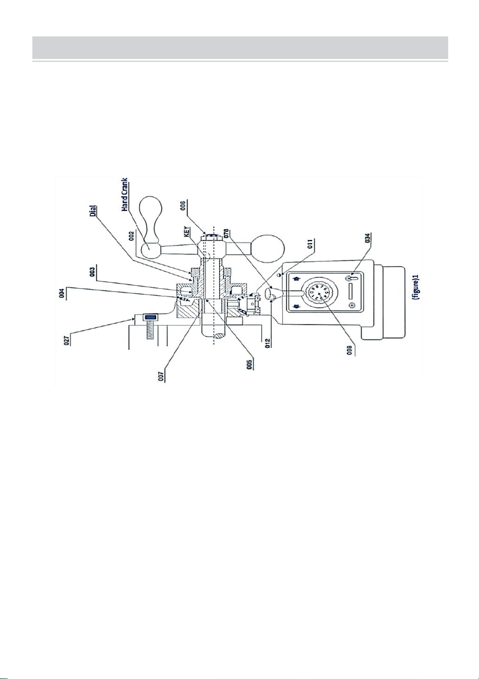
- 4 -
DRIVE INSTALLATION
Krok 1 : zdejmij korbę ręczną, tarczę i kołnierz łożyska z prawej strony
stołu.
Krok 2: Zamontować zasilacz z adapterem (027) w miejscu kołnierza
łożyska. Zamontuj adapter na końcu stołu za pomocą czterech nakrętek
sześciokątnych. Śruba, która należy zakończyć w kroku 3, zapewnia
prawidłowe położenie śruby pociągowej
Krok 3: Nasuń pierścień wewnętrzny (007) na śrubę pociągową ławce, a
następnie wsuń się do otworu the łożysko igiełkowe zasilania
elektrycznego. Na koniec pierścień wewnętrzny powinien stykać się z
występem elektrody scrProszę powrócić do rysunku 1 (027007)
Krok 4: Włóż klucz w rowek na śrubie pociągowej
Krok 5: Nałóż smar na bazie grafitu na zęby przekładni stożkowej (004).
Nałóż niewielką ilość nasmarować wewnętrzną powierzchnię przekładni
kołnierz .
Krok 6: Przymocuj przekładnię stożkową do śruby pociągowej za pomocą
klucza i naciśnij do góry. Koło napędowe (061). Uwaga: Zwykle przed
zamontowaniem przekładni stożkowej (004) należy założyć kilka
elementów dystansowych. (005) w pierścień wewnętrzny (007) i koło
zębate stożkowe (004), aby uzyskać jak najmniejszy luz pomiędzy zespół
przekładni. Liczba zastosowanych podkładek dystansowych (005) jest

- 5 -
określana na podstawie testu. Proszę zapoznać się z rysunkiem
1:(005,004) itp
Krok 7: Zgodnie z rysunkiem 1, zainstaluj odpowiednie pokrętło na
przekładni stożkowej (CLO04) i blisko kołnierz zasilający (nie dotykać się!).
Może być wtedy potrzebnych kilka podkładek dystansowych (CLO03).
spotkać powyższe wymagania.
Krok 8: Wkręcić nakrętkę (002) w przekładnię stożkową, aby zapobiec
poluzowaniu się tarczy
Krok 9: Złóż ponownie ręczną rangę c i zdejmij go w kroku 1 na śrubę
pociągową. Następnie dokręć skos przekładnię (004) lub użyj nakrętki
zabezpieczającej (006), aby ją dokręcić
RESTRICTED ASSEMBLY INSTALLATION
Zasilacz wyposażony jest w zespół wyłącznika krańcowego (051) i zespół
zatrzymujący przekładnię (095). Montuje się go w następujący sposób
(patrz rysunek 2):
Krok 1: Wyjmij oryginalny zespół ogranicznika ruchu ze stołu
warsztatowego i zamontuj dostarczony zespół ogranicznika ruchu (B18).
Krok 2: Usuń oryginalny blok krańcowy i zamontuj dostarczony zespół
wyłącznika krańcowego (B05).
Zwróć uwagę
1. Upewnij się, że kierunek osiowy zespołu wyłącznika krańcowego (051) i
zespołu dwustykowego ogranicznika ruchu (B18) pręta powinien
znajdować się na tej samej osi.
2. Ze względu na bezwładność odległość montażowa zespołu ogranicznika
ruchu (095) powinna być mniejsza niż a kilka milimetrów przesuwu
3. Chroń przewód zasilający wyłącznika krańcowego. Nie pozwól, aby
zaplątał się w ruchome części lub stoły.

- 6 -
Działanie zasilacza wygląda następująco (patrz rysunek 3):
Krok 1: Upewnij się, że przełącznik (034) znajduje się w pozycji „Off” i że
zespół dźwigni sterującej (078) znajduje się w pozycji neutralnej
(środkowej).
Krok 2: Podłącz kabel zasilający elektrowni do odpowiedniego gniazdka
Krok 3: Ustaw przełącznik w pozycji „ON”, wówczas nadajnik optyczny
(011) powinien się zaświecić
Krok 4: Obróć dźwignię sterującą (078) z pozycji środkowej w jednym
kierunku, wówczas stół przesunie się w tym samym kierunku. Zwiększ
prędkość zgodnie z ruchem wskazówek zegara, aby sterować zespołem
pokrętła (096), a następnie wyreguluj stół warsztatowy, aby poruszać się z
prędkością, która będzie stopniowo rosnąć.
Krok 5: Jeśli chcesz zmienić kierunek stołu, obróć przełącznik, aby
utrzymać uchwyt w środkowym położeniu, aż do wyłączenia zasilania.
Następnie obróć dźwignię sterującą w żądanym kierunku
(Przed zmianą kierunku upewnij się, że zasilanie jest wyłączone)

- 7 -
OGŁOSZENIE
1 . Prędkość jest kontrolowana przez
PRĘDKOŚĆ KONTROLA ZESPÓŁ
POKRĘTŁA(B19). Pozycja „o” oznacza
„stop” ang „g” oznacza najwyższą
prędkość.
7. PRZYCISK SZYBKIEGO
PRZEŁĄCZANIA (012) służy do szybki
ruch stołu Po jego naciśnięciu, wtedy stół
będzie poruszał się z dużą prędkością.
PERIODIC MAINTENANCE
11. Czyść maszynę co 250 godzin, np. ze względu na zmianę kierunku
wirnika, gromadzenie się węgla i inne brud wewnątrz maszyny, aby
zapewnić izolację.
12. Smarowanie: wlać olej smarowy do przekładni i rozsmarować smar na
grafitowej podstawie przekładni zęby
BRUSH POSITION
Krok 1: Zdejmij nasadkę szczotki (053) (patrz Rysunek 4). Wtedy może
wyskoczyć szczotka (050). Nie puszczaj pędzla. Jeśli szczoteczka nie
wyskakuje, delikatnie wyjmij ją końcówką śrubokręta.
Krok 2: Sprawdź wklęsłość pędzla. Powierzchnia powinna być gładka i
czysta. Jeśli zauważysz duże zadrapania na szczotce, odpadną jej części
lub pozostała długość szczotki wynosi tylko 6 mm, natychmiast wymień ją
na zatwierdzoną szczoteczkę zamienną. Jeśli jest to tylko brudny pędzel,
możesz go przetrzeć ołówkiem i gumką, aby usunąć zalegające plamy na
pędzlu.
Krok 3: Szczotka posiada sprężynę i mosiężną zatyczkę. Obróć mosiężny

- 8 -
korek, aż zęby znajdą się w pozycji pionowej, a następnie wsuń szczotkę w
uchwyt szczotki (052). Wkręcić nasadkę szczotki w otwór szczotki i
dokręcić.
PARTS LIST

- 9 -

- 10 -
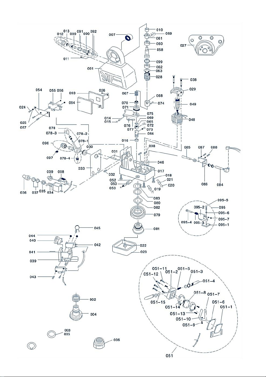
- 11 -
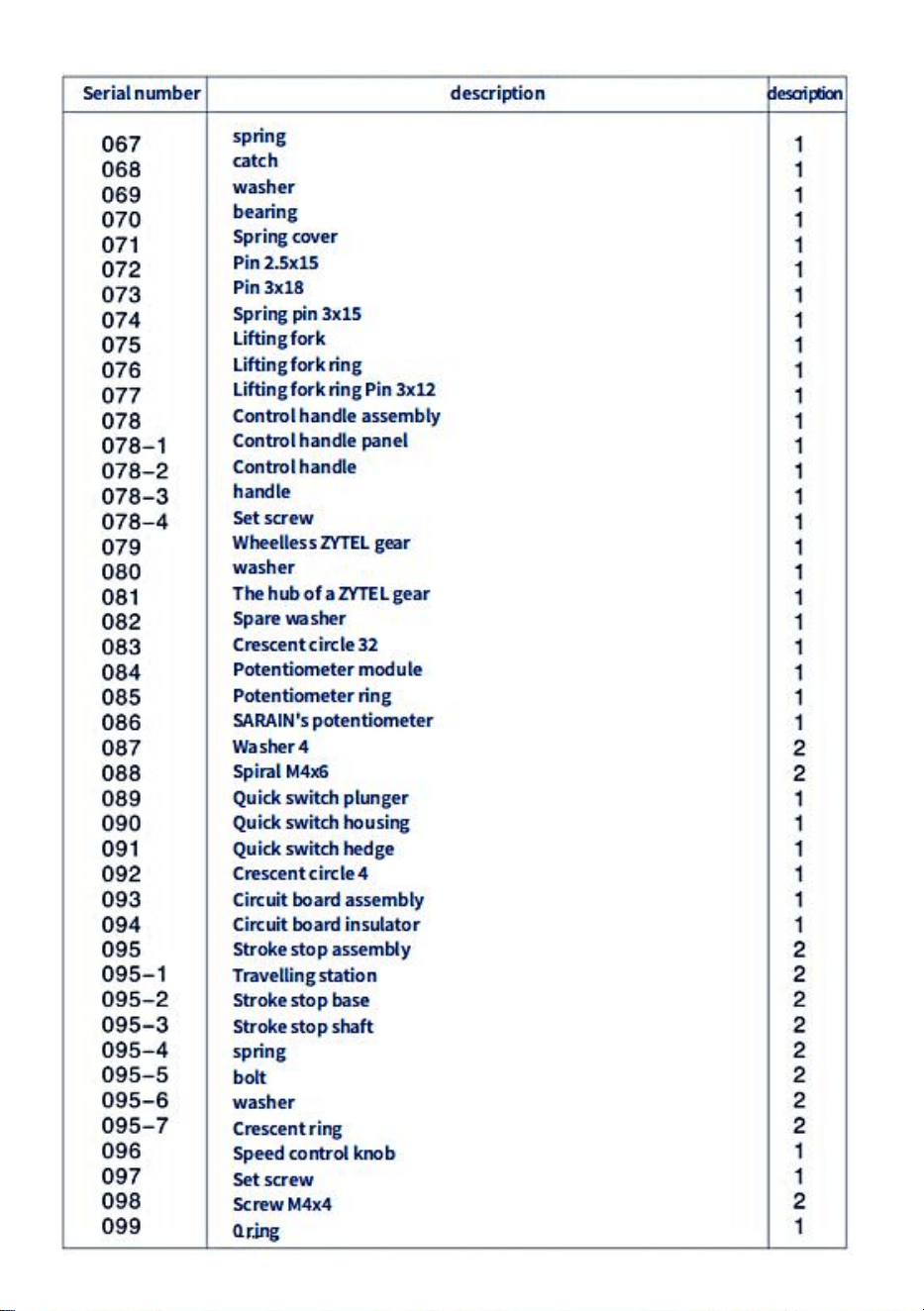
- 12 -

- 13 -
TROUBLESHOOTING
problem _ _
Przyczyny i rozwiązania
Emiter światła tak
nie emitować światło
1.Moc zasilanie lub połączenie kablowe są
uszkodzone
2. Bezpiecznik jest uszkodzony
3. Przełącznik (034) nie jest w pozycji „Włączony”
lub jest
uszkodzony.
4. Jeśli silnik można przesunąć, nadajnik optyczny
jest uszkodzony
Silnik nie działa
(078) w lewo lub w prawo,
kiedy uchwyt sterujący jest
wciśnięty .
1. Silnik obraca się po naciśnięciu szybkiego
przycisku (012).
①pokrętło regulacji prędkości nie jest W pozycję
„0”.
②Potencjometr (084) nie działa prawidłowo
③Uszkodzona płytka drukowana (003).
2.Naciśnij szybki przycisk (012), silnik się nie obraca
①szczotka i rotor kontakt jest zły lub pędzel jest
zużyty obwód w
②jest zepsuty
opis
1.Występuje zwarcie pomiędzy szczotką (050) I
pokrywę zasilacza (017). Lub występuje zwarcie w
wyłączniku krańcowym (051)
2. Proszek węglowy w szczotce węglowej powoduje
zwarcie.
Nie można uzyskać dużej
prędkości przycisk
szybkiej prędkości, gdy
wciśnięty (012)
Mikroprzełącznik (055) pod szybkim przyciskiem
(012) nie jest połączony
Silnik nie działa (078)w
lewo lub w prawo, kiedy
uchwyt sterujący Jest
prasowany
1. Nie działa szybki przycisk (012) i mikro
przełącznik (055) jest podłączony.
2.Sterowany prostownik (BT141) na opór
(MYG14K) płytka drukowana krzemowa ma zwarcie
państwo.
Stół przesunął się o godz
niespotykana prędkość
Śruba pociągowa tego stołu nie jest wystarczająco
dobra.

- 14 -
CIRCUIT DIAGRAM

- 15 -
INSTRUCTIONS FOR INSTALLING CROSS FEEDS

- 16 -
Śruby pociągowe o skoku poprzecznym nie powinny być modyfikowane w celu
zapewnienia idealnej instalacji
INSTALL T-SLOTS FOR TRANSVERSE FEED
HOW TO INSTALL KNEE LIFT FEED
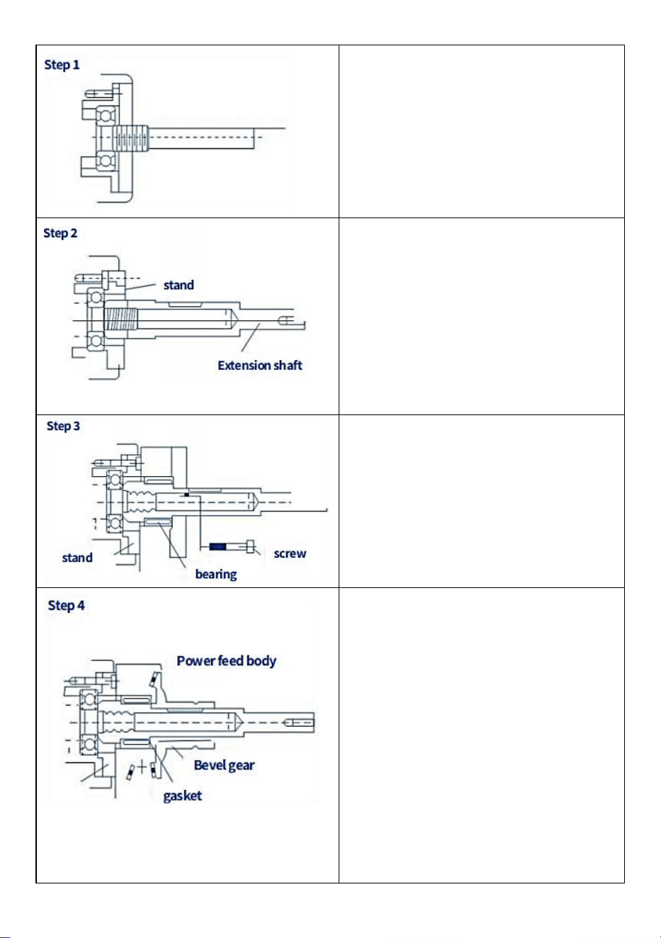
- 17 -
Zdemontować korbę ręczną, tarczę,
kołnierz łożyska tarczy i ·.... · Itp.
Montaż wału przedłużającego
Ważne sprawy:
(1) Koniec wału musi znajdować się
blisko pierścienia wewnętrznego
łożyska
(2) Wał wewnętrzny ma gwint 16 lub
18 uncji.
Dokręcić podpórkę do kołnierza, a
następnie dokręcić podkolannik do
kołnierza. Co ważne, służy do
pozycjonowania kątowego.
Klucz do wyposażenia
zabezpieczającego nie jest włożony
Ręcznie popchnij i obróć przekładnię
stożkową, aby sprawdzić luz.
(1) Jeśli to konieczne, dodaj kilka
elementów dystansowych, aby
uzyskać odpowiednie dopasowanie
reakcja.
(2) Wyreguluj krawędź natarcia
przekładni, aby uzyskać odpowiedni
luz z tyłu. Następnie ponownie
nasmaruj przekładnię smarem.
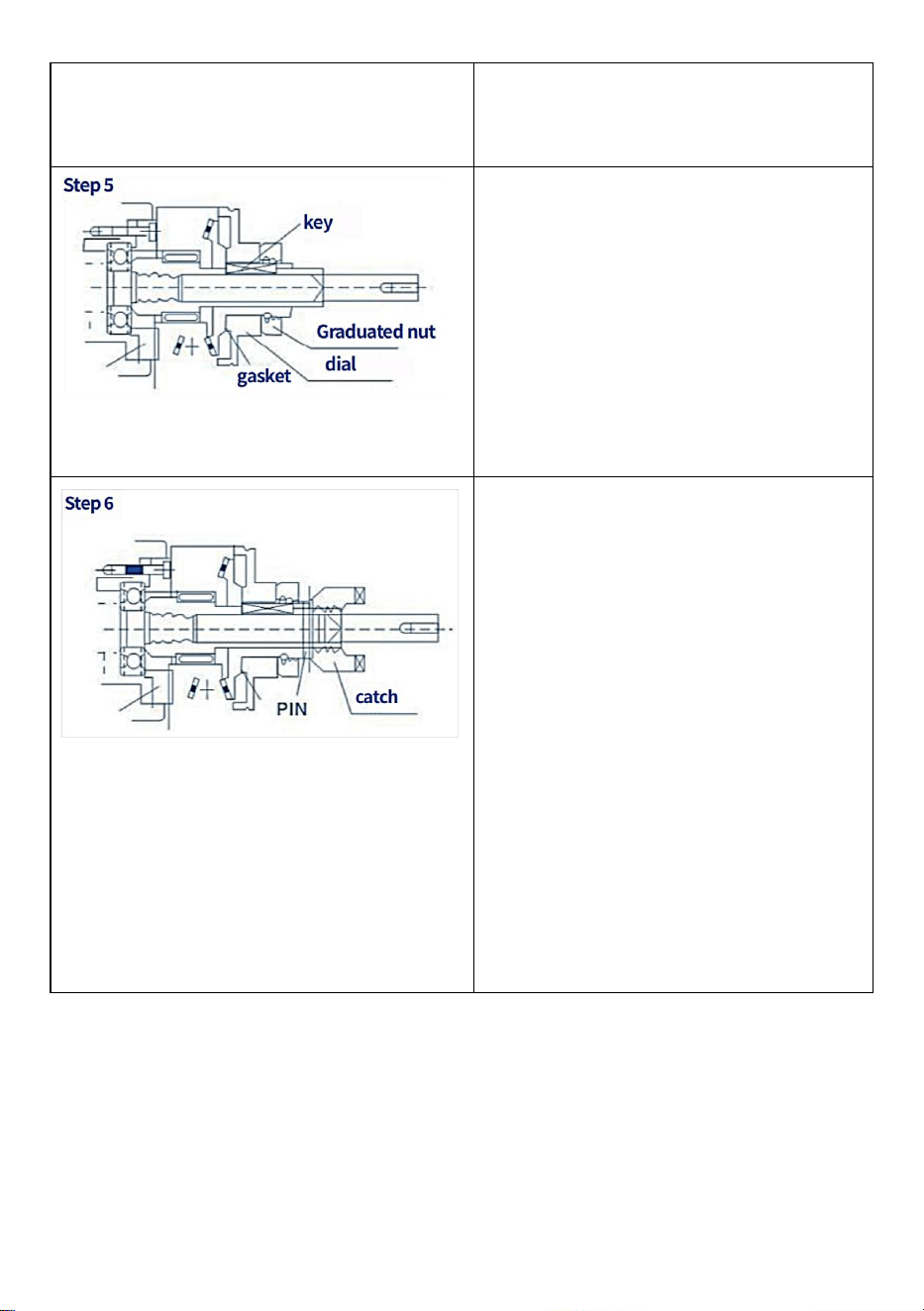
- 18 -
Zamontuj ponownie przekładnię, a
następnie naciśnij i obróć, aby
sprawdzić luz
Po zakończeniu kroku ( 4 ) zdemontuj
przekładnię stożkową, następnie
zamontuj wpust, wymień przekładnię,
zamontuj tarczę, dokręć nakrętkę
tarczy (dodaj kilka małych kawałków
przekładni szlifierskiej). Przed
montażem przekładnię nasmaruj
smarem (nie używaj smaru
silikonowego).
Zamontuj pręt kontrolny na przekładni
stożkowej i wywierć go w otworze o
średnicy 5 mm. Następnie wbij
sworzeń sprężynowy.
Jedno ważne uwaga: Przed
zamontowaniem kołka
sprężynującego upewnij się, że każdy
krok został wykonany dokładnie i
poprawnie. Zaleca się zainstalowanie
ręcznej korby i obrócenie jej w
kierunku zgodnym z ruchem
wskazówek zegara w celu
sprawdzenia, czy potencjał arkusza
jest prawidłowy i czy nie występuje
zacięcie.
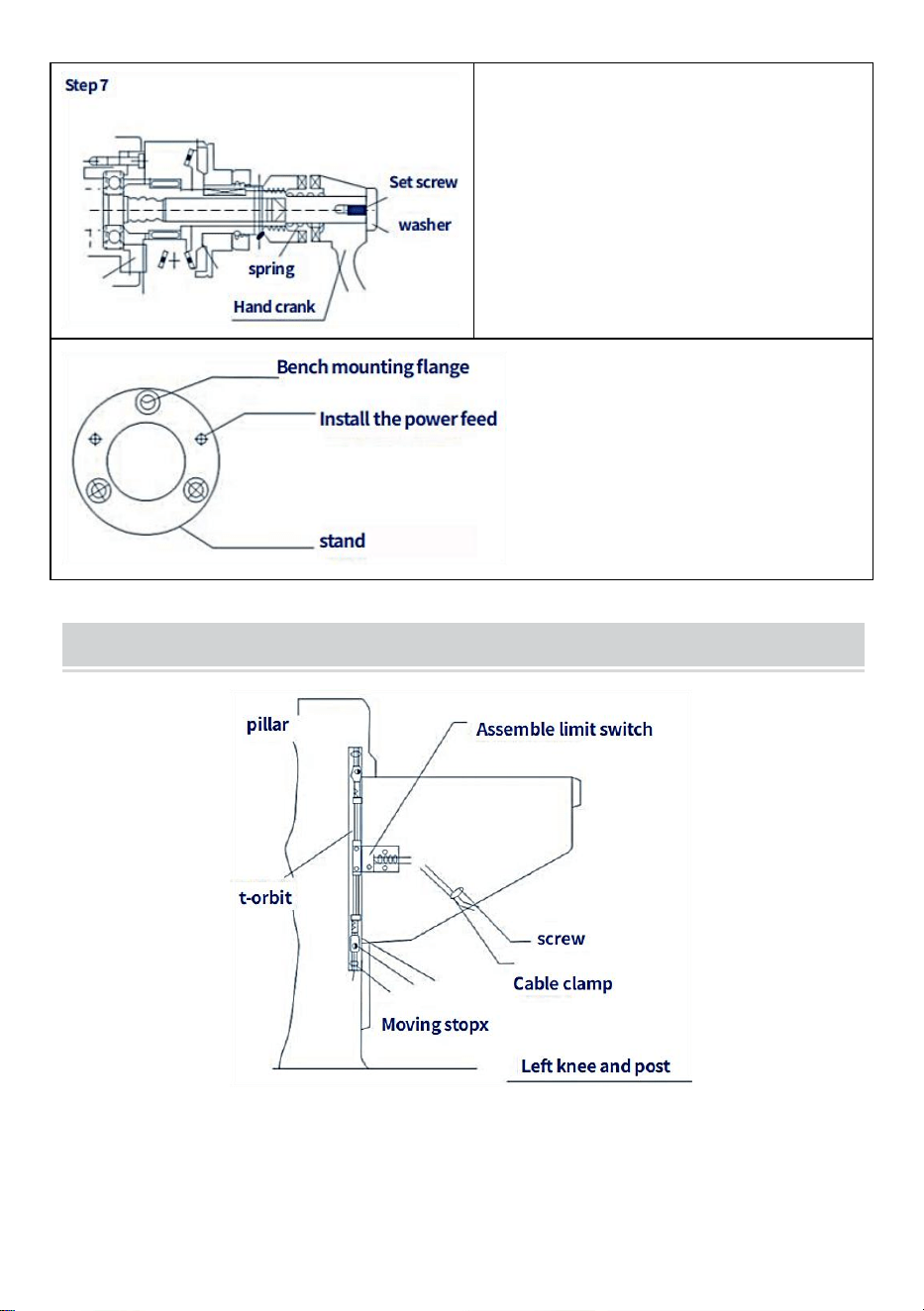
- 19 -
Zamontuj korbę sprężynową (już
zainstalowaną), a następnie dokręć
podkładkę i śruby . Ważne jest, aby
nasmarować tę część i postępować
zgodnie z instrukcjami dotyczącymi
bezpiecznej obsługi.
INSTALL T - RAIL LIFT FEED
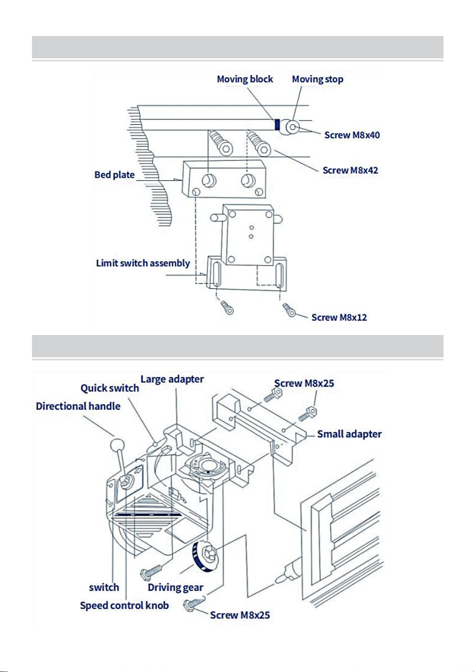
- 20 -
ASSEMBLY - LIMIT ASSEMBLY INSTRUCTIONS
LONGITUDINAL FEED - HORIZONTAL ARRANGEMENT

- 21 -
montaż
1 . Przesuń pomost maksymalnie w lewo
2. Zdejmij korbę ręczną, tarczę i kołnierz łożyska z toru startowego.
3. W razie potrzeby zamontować wałek przedłużający do stołu T i
zamontować napęd
bieg.
4. Wykręć dwie śruby (M8 x 25) z małego adaptera.
5. Zamontuj poziomo zasilacz na dużym adapterze.
6. Wyreguluj położenie i luz kół zębatych
7. Dokręć śruby na kole napędowym.
8. Dokręć dwie śruby małego adaptera (2-M8x25)
9. Nałóż trochę smaru grafitowego na zęby przekładni
Sanven Technology Ltd.
Adres: Suite 250, 9166 Anaheim Place, Rancho Cucamonga,
Kalifornia 91730
Wyprodukowano w Chinach


- 2 -
Technisch Ondersteuning en e-garantiecertificaat
www.vevor.com/support
MOLENKRACHTTAFELVOEDING
MODEL:AL-450
We continue to be committed to provide you tools with competitive price.
"Save Half", "Half Price" or any other similar expressions used by us only represents an
estimate of savings you might benefit from buying certain tools with us compared to the major
top brands and does not necessarily mean to cover all categories of tools offered by us. You
are kindly reminded to verify carefully when you are placing an order with us if you are
actually saving half in comparison with the top major brands.

- 1 -
MODEL:AL-450
Have product questions? Need technical support? Please feel free to
contact us:
Technical Support and E-Warranty Certificate
www.vevor.com/support
NEED HELP? CONTACT US!
This is the original instruction, please read all manual instructions
carefully before operating. VEVOR reserves a clear interpretation of our
user manual. The appearance of the product shall be subject to the
product you received. Please forgive us that we won't inform you again if
there are any technology or software updates on our product.
MILL POWER TABLE FEED

- 2 -
BRIEF INTRODUCTION
Welkom bij het gebruik van deze krachtbron. Het zal uw werk gemakkelijk
maken en u gelukkig maken. Lees deze handleiding zorgvuldig door voor
de montage en het gebruik van deze machine.
Geschikt voor alle feeders van verticale revolverfreesmachines, inclusief
maar niet beperkt tot Bridgeport, precisie
Matthews,grizzly,enco,jet,sharp,Webb,GMC, Clark,supermax,turn
pro,vectrax,acra,Birmingham,accu,first en meer,Als u freest met dezelfde
installatiemodus en een as met een diameter van 5/8" het einde. Zolang
het een machine van het Bridgeport-type is, moet deze geschikt zijn. (Hij is
niet geschikt voor freesmachines met verschillende installatiemodi of
draadspindels van verschillende afmetingen, zoals Powermatic en enkele
andere machines van vreemde afmetingen, dus alstublieft zorg ervoor dat
uw machine van het typische Bridgeport-type hierboven is)
SAFETY WARNINGS AND PRECAUTIONS
1. Houd de werkplek schoon. Gebruik deze machine niet op natte plaatsen.
Gebruik deze machine niet in de aanwezigheid van brandbare gassen of
vloeistoffen.
2. De stroomvoorziening moet worden afgestemd op de voeding.
3. De schakelaar (034) moet in de 'uit'-positie staan voordat deze niet
wordt gebruikt of geplaatst
4. Plaats niets anders op de machine. Vermijd het morsen van water of
andere vloeistoffen op de machine
5. Niet doen probeer de capaciteit van het gereedschap te overschrijden
door ongeschikte hulpstukken te gebruiken.
6. Onderhoud gereedschap zorgvuldig.

- 3 -
SPECIFICATIONS
Model
Snelh
eid
Maximaal
Opbrengst Snelheid
Maximaal
koppel
Spanning
AL-260
0~ 20
0
2 77 tpm
1385 mm/min (externe
schroefkabel 5 mm)
450in-lb
110V(220V-240
V)50/60Hz
AL-310
0~ 20
0
2 77 tpm
1385 mm/min (externe
schroefkabel 5 mm)
450in-lb
110V(220V-240
V)50/60Hz
AL-450
0~ 20
0
2 77 tpm
1385 mm/min (externe
schroefkabel 5 mm)
450in-lb
110V(220V-240
V)50/60Hz
OPEN THE BOX
Projectbeschrijving
Hoeveelheid
Koperen tandwielpakking
1
Installeer de borgplaat
1
Platte sleutel
1
Vulring aanpassen
15
Eindschakelaar waterdichte doos
1
Eindschakelaarveer g
2
Limiet blok
2
Montage schroef
4
Koperen tandwiel
1
Verlengde schacht
1
Verlengde asveer
1
DRIVE INSTALLATION
Stap 1 : verwijder de handslinger, de draaiknop en de lagerflens aan de
rechterkant van de tafel.
Stap 2: Installeer de krachttoevoer met de adapter (027) in de positie van
de lagerflens. Monteer de adapter aan het uiteinde van de tafel met behulp
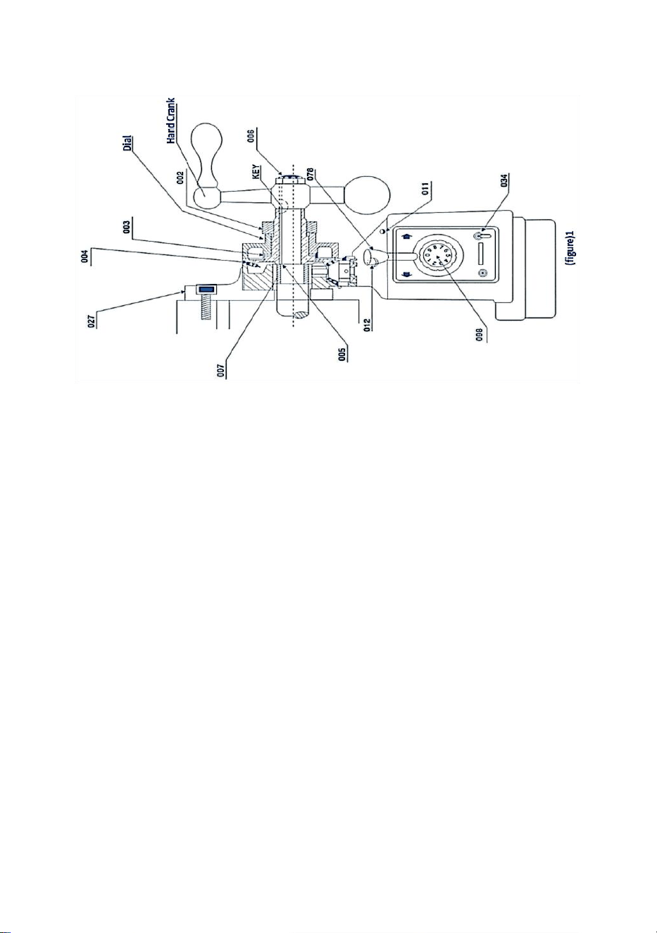
- 4 -
van vier zeskantmoeren. De schroef, die moet worden voltooid met stap 3,
zorgt voor de juiste positie van de spindel
Stap 3: Schuif de binnenring (007) op de spindel van de bank, en schuif
dan in het gat van de naaldlager met elektrische voeding. Ten slotte moet
de binnenring contact maken met de schouder van de riem screGa terug
naar figuur 1(027007)
Stap 4: Steek de sleutel in de spiebaan op de spindel
Stap 5: Breng vet op grafietbasis aan op de tanden van het kegeltandwiel
(004). Breng een kleine hoeveelheid aan vet op het binnenoppervlak van
het tandwiel flens .
Stap 6: Bevestig het kegeltandwiel met de sleutel aan de spindel en druk
deze omhoog. Aandrijftandwiel (061). Let op: Normaal gesproken moeten
er meerdere afstandshouders worden geplaatst voordat het kegeltandwiel
(004) wordt gemonteerd. (005) in de binnenring (007) en het kegeltandwiel
(004) om een zo klein mogelijke speling tussen de tandwielen te verkrijgen
tandwielmontage. Het aantal afstandshouders (005) dat u gaat gebruiken,
wordt bepaald door uw test. Zie Figuur 1:(005.004), enz
Stap 7: Zie afbeelding 1, installeer de juiste wijzerplaat op het
kegeltandwiel (CLO04) en dicht bij de voedingsflens (raak elkaar niet aan!).
Er kunnen dan meerdere afstandhouders (CLO03) nodig zijn ontmoeten
bovenstaande eisen.
Stap 8: Schroef de moer (002) in het kegeltandwiel om te voorkomen dat
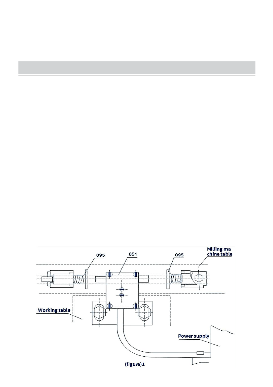
- 5 -
de wijzerplaat losraakt
Stap 9: Monteer de handmatige c -rangschikking opnieuw en verwijder
deze in stap 1 op de spindel. Draai vervolgens de schuine kant vast
tandwiel (004), of gebruik de borgmoer (006) om deze vast te draaien
RESTRICTED ASSEMBLY INSTALLATION
De krachttoevoer is uitgerust met een eindschakelaarsamenstel (051) en
een transmissiestopsamenstel (095). Het wordt als volgt gemonteerd (zie
afbeelding 2):
Stap 1: Verwijder de originele slagbegrenzer van de werkbank en monteer
de meegeleverde slagbegrenzer (B18).
Stap 2: Verwijder het originele eindblok en monteer het meegeleverde
eindschakelaarsamenstel (B05).
Let op
1. Zorg ervoor dat de axiale richting van de eindschakelaar (051) en de
slagbegrenzer met twee contacten (B18) van de stang zich op dezelfde as
bevinden.
2. Vanwege de traagheid moet de installatieafstand van de slagbegrenzer
(095) kleiner zijn dan a enkele millimeters veerweg
3. Bescherm het netsnoer van de eindschakelaar. Zorg ervoor dat het niet
verstrikt raakt in bewegende delen of tafels.
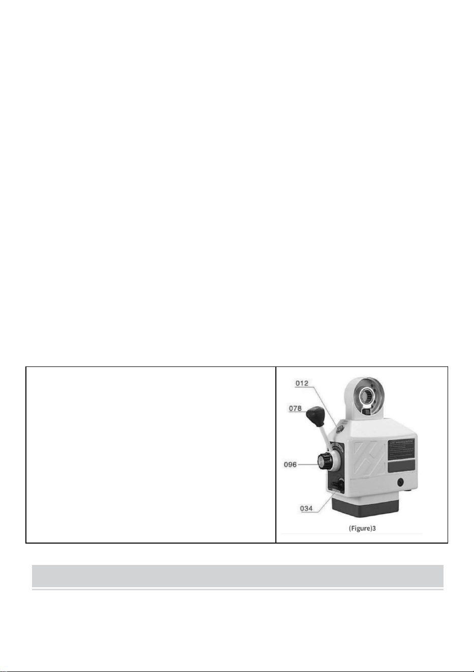
- 6 -
De werking van de stroomtoevoer is als volgt (zie Figuur 3):
Stap 1: Zorg ervoor dat de schakelaar (034) in de stand "Uit" staat en dat
de bedieningshendel (078) in de neutrale (midden) stand staat.
Stap 2: Sluit de voedingskabel van het krachtstation aan op het daarvoor
bestemde stopcontact
Stap 3: Zet de schakelaar in de stand "ON", dan moet de optische zender
(011) oplichten
Stap 4: Draai de bedieningshendel (078) vanuit de middenpositie naar één
richting, waarna de tafel in dezelfde richting beweegt. Verhoog de snelheid
met de klok mee om de knopconstructie (096) te bedienen, en pas
vervolgens de werkbank aan zodat deze beweegt met een snelheid die
geleidelijk toeneemt.
Stap 5: Als u de richting van de tafel wilt veranderen, draait u de
schakelaar om de hendel in de middelste stand te houden totdat de stroom
is uitgeschakeld. Draai vervolgens de bedieningshendel in de gewenste
richting
(Zorg ervoor dat de stroom is uitgeschakeld voordat u van richting
verandert)
KENNISGEVING
1 . De snelheid wordt geregeld door de
SPEED CONTROLE KNOP ASSY(B19).
Positie “o” vertegenwoordigt "stop" ang “g”
staat voor de hoogste snelheid.
8. SNELLE SCHAKELKNOP (012)is voor
snelle beweging van de tafel Wanneer erop
wordt gedrukt, dan beweegt de tafel met
hoge snelheid.
PERIODIC MAINTENANCE
13. Maak de machine elke 250 uur schoon, bijvoorbeeld bij verandering
van rotorrichting, koolstofophoping en dergelijke vuil in de machine, om

- 7 -
isolatie te garanderen.
14. Smering, plaats de smeerolie in het tandwiel en smeer het vet op het
grafietbasistandwiel tanden
BRUSH POSITION
Stap 1: Verwijder de borstelkap (053) (zie Figuur 4). Dan kan de borstel
(050) omhoog springen. Laat de borstel niet los. Als de borstel niet loskomt,
verwijder deze dan voorzichtig met de punt van een schroevendraaier.
Stap 2: Controleer de concaaf van de borstel. Het oppervlak moet glad en
schoon zijn. Als u grote krassen op de borstel opmerkt, of als er delen van
de borstel zijn gevallen, of als de resterende lengte van de borstel slechts
6 mm bedraagt, vervang dan de borstel onmiddellijk door een
goedgekeurde vervangingsborstel. Als het gewoon een vuile borstel is, kun
je de borstel schoonvegen met een potlood en een gum om eventuele
achtergebleven vlekken van de borstel te verwijderen.
Stap 3: De borstel heeft een veer en een messing plug. Draai de koperen
plug totdat de tanden verticaal staan en druk vervolgens de borstel in de
borstelhouder (052). Schroef de borsteldop in het borstelgat en draai vast.

- 8 -
PARTS LIST

- 9 -

- 10 -
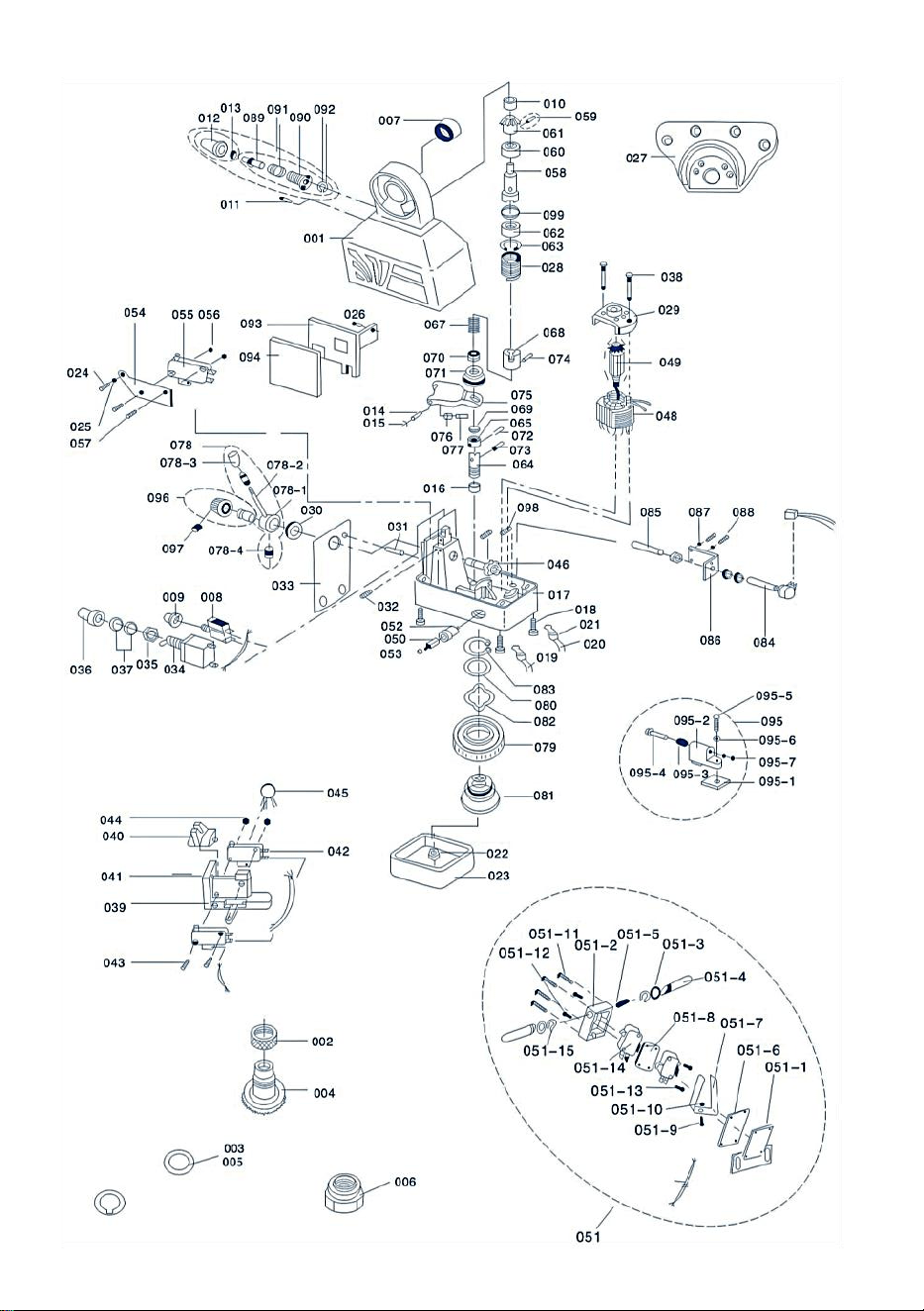
- 11 -

- 12 -

- 13 -
TROUBLESHOOTING
probleem _ _
Oorzaken en oplossingen
De lichtzender wel
niet licht uitstralen
1.De kracht voeding of kabelaansluiting is defect
2.De stroomonderbreker is beschadigd
3.Schakelaar(034)staat niet in de "Aan"-positie of is
dat wel
beschadigd.
4.Als de motor kan worden verplaatst, is de optische
zender beschadigd
De motor werkt niet
(078) links of rechts
wanneer de
bedieningshendel is
ingedrukt .
1.De motor draait wanneer de snelknop (012) wordt
ingedrukt
①De snelheidsregelknop is dat niet in de "0"-positie
②Potentiometer(084)werkt niet goed
③Circuitplaat (003)beschadigd
2. Druk op de snelknop (012), de motor draait niet
①borstel en rotor het contact is slecht of de borstel
is opgebruikt.De circuit in
②is kapot
beschrijving
1.Er is kortsluiting tussen de borstel (050) En het
deksel van de stroomtoevoer (017). Of er is
kortsluiting in de eindschakelaar (051)
2.Het koolstofpoeder in de koolborstel veroorzaakt
kortsluiting.
Kan geen hoge snelheid
halen hogesnelheidsknop
wanneer
ingedrukt (012)
De microschakelaar (055) onder de snelknop (012)
niet verbonden
De motor werkt niet
(078)links of rechts
wanneer de
bedieningshendel is
ingedrukt
1. De snelknop (012) werkt niet, en de micro
schakelaar (055) is aangesloten.
2. De gestuurde gelijkrichter (BT141) op de
weerstand
(MYG14K)siliciumprintplaat is kortgesloten
staat.
De tafel bewoog met een
ongekende snelheid
De spindel van deze tafel is niet goed genoeg.

- 14 -
CIRCUIT DIAGRAM

- 15 -
INSTRUCTIONS FOR INSTALLING CROSS FEEDS
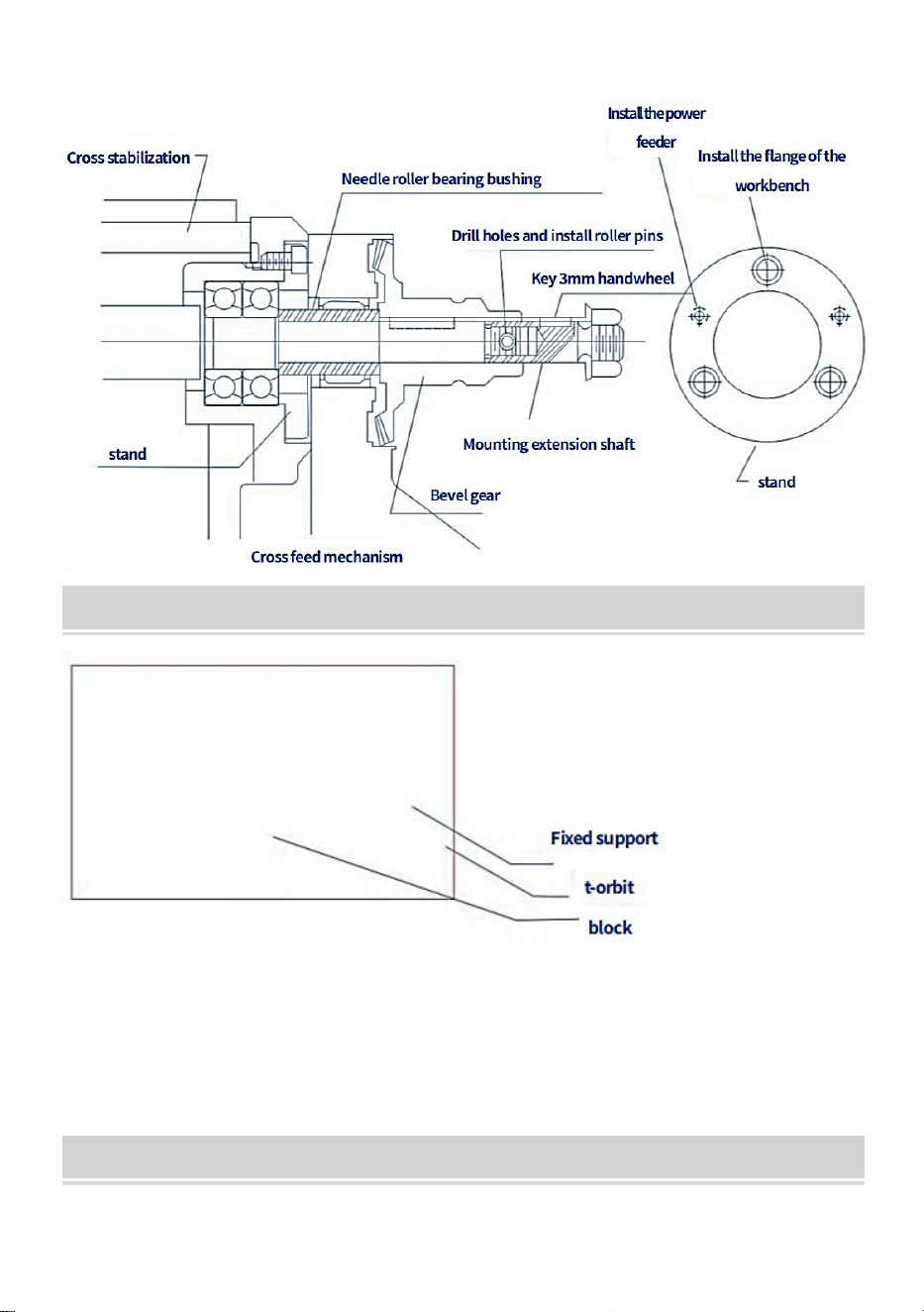
- 16 -
Spindels met dwarsslag mogen niet worden aangepast voor een ideale installatie
INSTALL T-SLOTS FOR TRANSVERSE FEED
HOW TO INSTALL KNEE LIFT FEED
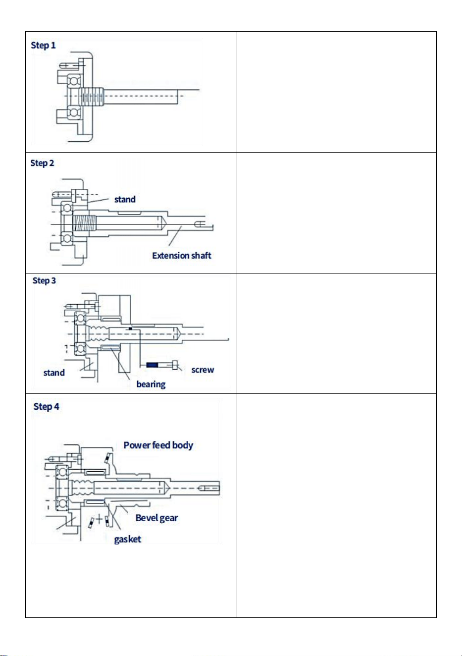
- 17 -
Verwijder de handslinger, de
wijzerplaat, de wijzerplaatlagerflens
en ·.... · Enz.
Montage verlengas
Belangrijke zaken:
(1) Het asuiteinde moet zich dicht bij
de binnenring van het lager bevinden
(2) De binnenas is 16 of 18 draad unc.
Draai de steun vast op de flens en
draai vervolgens de kniesteun vast op
de flens. Belangrijk is dat het wordt
gebruikt voor hoekpositionering.
De sleutel van het
veiligheidsmechanisme is niet
ingestoken
Duw en draai het kegeltandwiel met
de hand om de speling te controleren.
(1) Voeg indien nodig enkele
afstandhouders toe om de juiste maat
te krijgen verzet.
(2) Stel de voorrand van het tandwiel
af om de juiste speling aan de
achterkant te verkrijgen. Verpak het
tandwiel vervolgens opnieuw met vet.
Plaats het tandwiel terug en druk en
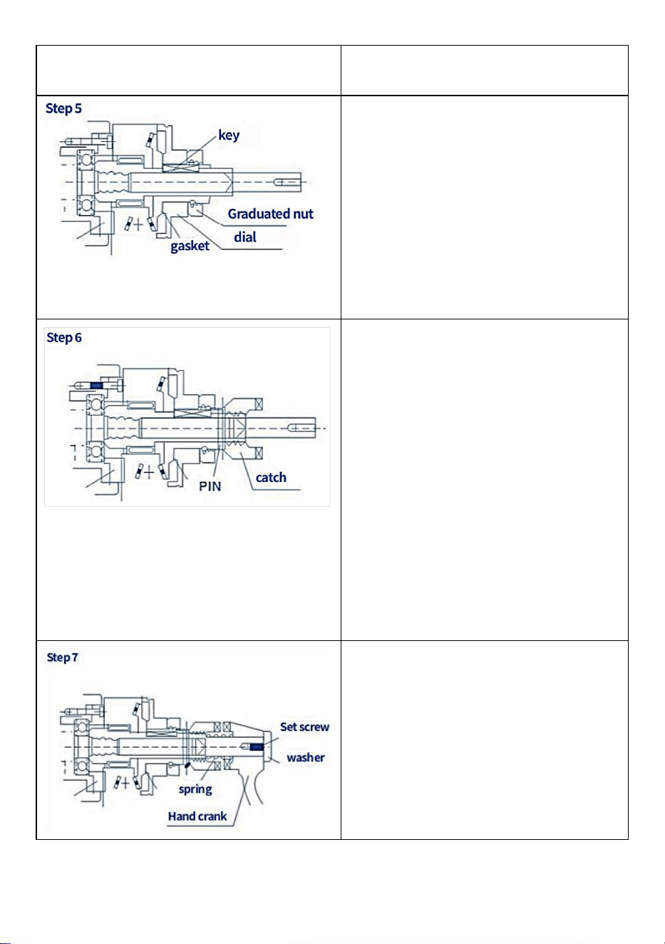
- 18 -
draai vervolgens om de speling te
controleren
Nadat stap ( 4 ) is voltooid, verwijdert
u het kegeltandwiel, installeert u
vervolgens de sleutel, vervangt u het
tandwiel, installeert u de wijzerplaat en
draait u de wijzerplaatmoer vast (voeg
een paar kleine stukjes slijptandwiel
toe). Verpak het tandwiel met vet
voordat u het installeert (gebruik geen
siliconenvet).
Installeer de controlestang op het
kegeltandwiel en boor deze in het gat
met een diameter van 5 mm.
Vervolgens de veerpen indrijven.
Eén belangrijk Let op: Zorg ervoor dat
u elke stap zorgvuldig en correct
uitvoert voordat u de drukknop
installeert. Het wordt aanbevolen om
een handmatige slinger te installeren
en deze met de klok mee te draaien
om te controleren of de potentiële
plaat correct is en of er sprake is van
vastzittende actie.
Installeer de veerkruk (reeds
geïnstalleerd) en draai vervolgens de
ring en de schroeven vast . Het is
belangrijk om dit onderdeel te smeren
en de instructies te volgen voor een
veilige bediening.
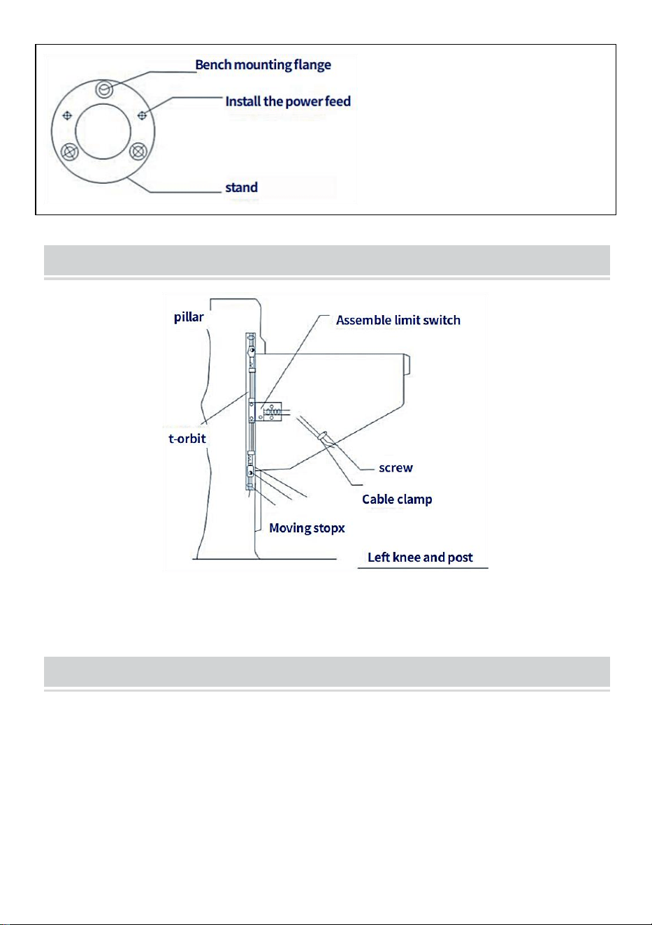
- 19 -
INSTALL T - RAIL LIFT FEED
ASSEMBLY - LIMIT ASSEMBLY INSTRUCTIONS

- 20 -
LONGITUDINAL FEED - HORIZONTAL ARRANGEMENT
montage
1 . Verplaats de loopbrug naar uiterst links

- 21 -
2. Verwijder de handslinger, de wijzerplaat en de lagerflens van de baan.
3. Indien nodig verlengingsas voor T-tafel monteren en aandrijving
monteren
versnelling.
4. Verwijder de twee schroeven (M8 x 25) uit de kleine adapter.
5. Installeer de stroomtoevoer horizontaal op de grote adapter.
6. Pas de positie en speling van de tandwielen aan
7. Draai de schroeven op het aandrijftandwiel vast.
8. Draai de twee schroeven van de kleine adapter (2-M8x25) vast
9. Smeer wat grafietvet op de tanden van het transmissietandwiel
Sanven Technologie Ltd.
Adres: Suite 250, 9166 Anaheim Place, Rancho Cucamonga, CA 91730
Gemaakt in China


- 2 -
Teknisk Support och e-garanticertifikat
www.vevor.com/support
KVARNKRAFTBORDSMATNING
MODELL: AL-450
We continue to be committed to provide you tools with competitive price.
"Save Half", "Half Price" or any other similar expressions used by us only represents an
estimate of savings you might benefit from buying certain tools with us compared to the major
top brands and does not necessarily mean to cover all categories of tools offered by us. You
are kindly reminded to verify carefully when you are placing an order with us if you are
actually saving half in comparison with the top major brands.

- 1 -
MODELL: AL-450
Have product questions? Need technical support? Please feel free to
contact us:
Technical Support and E-Warranty Certificate
www.vevor.com/support
NEED HELP? CONTACT US!
This is the original instruction, please read all manual instructions
carefully before operating. VEVOR reserves a clear interpretation of our
user manual. The appearance of the product shall be subject to the
product you received. Please forgive us that we won't inform you again if
there are any technology or software updates on our product.
MILL POWER TABLE FEED

- 2 -
BRIEF INTRODUCTION
Välkommen att använda detta kraftflöde. Det kommer att göra ditt jobb
bekvämt och göra dig lycklig. Läs denna bruksanvisning noggrant för din
montering och användning av denna maskin.
Lämplig för alla vertikala tornfräsmaskiner, inklusive men inte begränsat till
Bridgeport, precision Matthews,grizzly,enco,jet,sharp,Webb,GMC,
Clark,supermax,turn pro,vectrax,acra,Birmingham,accu,first och mer,Om
du fräser med samma installationsläge och 5/8" diameter axel vid slutet.
Så länge det är en maskin av Bridgeport-typ bör den vara lämplig.(den är
inte lämplig för fräsmaskiner med olika installationslägen eller blyskruvar
av olika storlekar, som powermatic och några andra maskiner i konstiga
storlekar, så snälla se till att din maskin är den typiska Bridgeport-typen
ovan)
SAFETY WARNINGS AND PRECAUTIONS
1. Håll arbetsområdet rent. Använd inte denna maskin på våta platser.
Använd inte denna maskin i närvaro av brandfarliga gaser eller vätskor.
2. Strömförsörjningen måste vara koordinerad med matningen.
3. Strömställaren (034) ska vara i "av"-läget innan den inte används eller
sätts in
4. Lägg inget annat på maskinen. Undvik att spilla vatten eller andra
vätskor på maskinen
5. Gör inte det försök att överskrida verktygets kapacitet genom att
använda olämpliga tillbehör.
6. Underhåll verktygen noggrant.

- 3 -
SPECIFICATIONS
Modell
Fart
Maximal
Lämna tillbaka Fart
Maximal
vridmomen
t
Spänning
AL-260
0~ 20
0
2 77 rpm
1385 mm/min (extern
skruvledning 5 mm)
450 in-lb
110V(220V-240
V)50/60Hz
AL-310
0~ 20
0
2 77 rpm
1385 mm/min (extern
skruvledning 5 mm)
450 in-lb
110V(220V-240
V)50/60Hz
AL-450
0~ 20
0
2 77 rpm
1385 mm/min (extern
skruvledning 5 mm)
450 in-lb
110V(220V-240
V)50/60Hz
OPEN THE BOX
Projekt beskrivning
Kvantitet
Kugghjulspackning av koppar
1
Montera hållarplattan
1
Platt nyckel
1
Justerar shim
15
Gränslägesbrytare vattentät låda
1
Gränslägesbrytare fjäder
2
Begränsa block
2
Monteringsskruv
4
Kopparredskap
1
Förlängt skaft
1
Förlängd axelfjäder
1
DRIVE INSTALLATION
Steg 1 : ta bort handveven, ratten och lagerflänsen från bordets högra sida.
Steg 2: Installera kraftmataren med adaptern (027) i läget för lagerflänsen.
Montera adaptern vid bordets ände med fyra sexkantsmuttrar. Skruven,
som ska avslutas med steg 3, säkerställer att ledskruven är korrekt
placerad
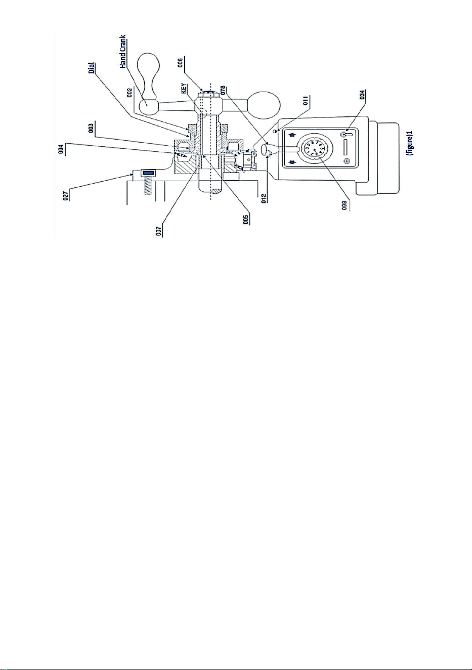
- 4 -
Steg 3: Skjut den inre ringen (007) på ledskruven på bänken och glid
sedan in i hålet på de kraftmatningsnåls rullager. Slutligen ska den inre
ringen komma i kontakt med ledningens skuldra scre Gå tillbaka till figur
1(027007)
Steg 4: Sätt in nyckeln i kilspåren på ledarskruven
Steg 5: Applicera grafitbasfett på tänderna på det koniska kugghjulet (004).
Applicera en liten mängd fett till växelns inre yta fläns .
Steg 6: Fäst det koniska kugghjulet på ledskruven med nyckeln och tryck
uppåt. Drivväxel (061). Notera: Vanligtvis bör flera distanser sättas in innan
det koniska kugghjulet (004) monteras. (005) i innerringen (007) och det
koniska kugghjulet (004) för att få minsta möjliga spel mellan
växelmontering. Antalet distanser (005) du kommer att använda bestäms
av ditt test. Se figur 1:(005,004), etc
Steg 7: Se figur 1, installera lämplig ratt på det koniska kugghjulet (CLO04)
och nära kraftmatningsfläns (rör inte varandra!) . Flera distanser (CLO03)
kan då behövas att möta ovanstående krav.
Steg 8: Skruva in muttern (002) i det koniska kugghjulet för att förhindra att
ratten lossnar
Steg 9: Sätt tillbaka den manuella veven och ta bort den i steg 1 på
ledarskruven. Dra sedan åt avfasningen kugghjul (004), eller använd
låsmuttern (006) för att dra åt den
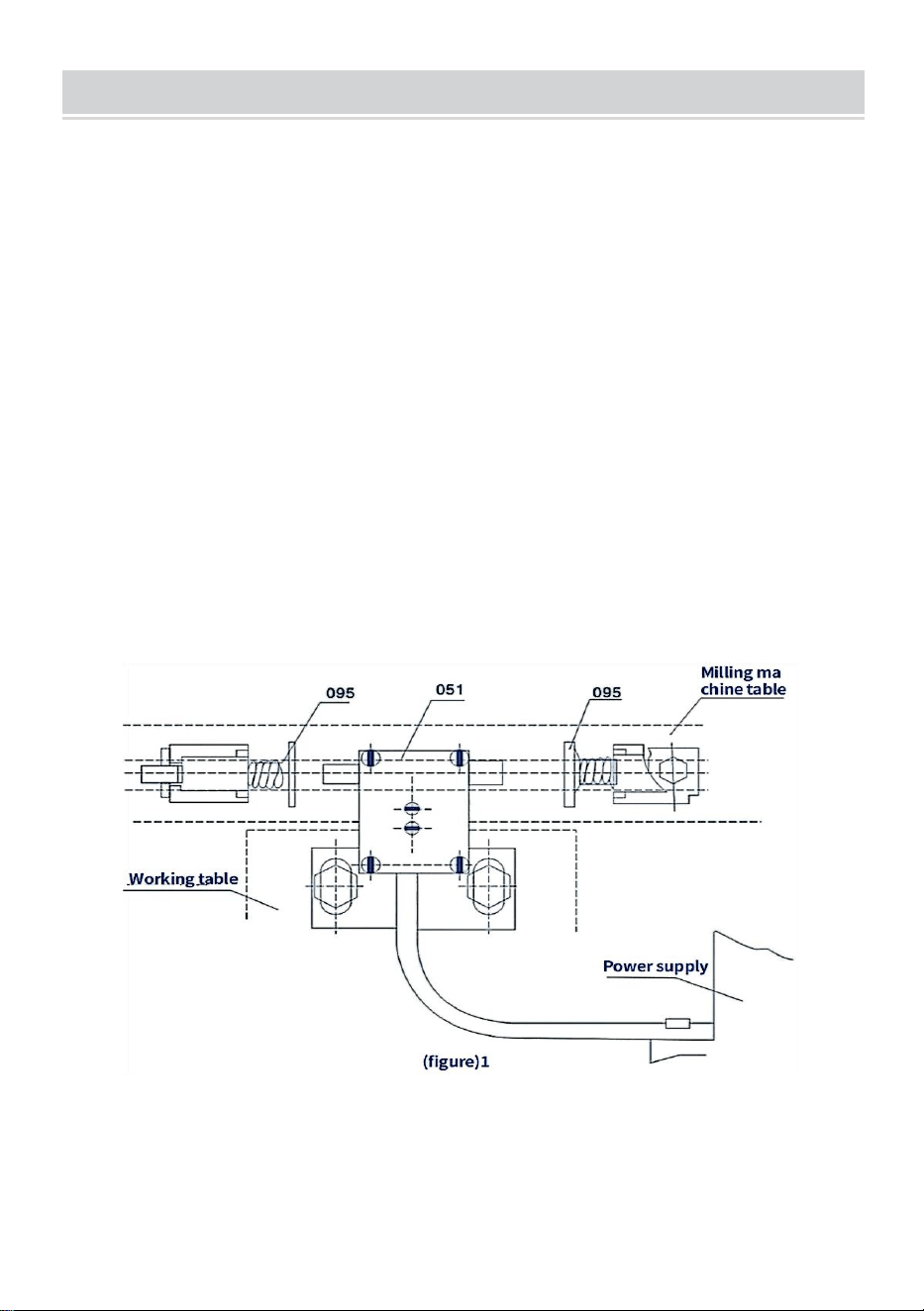
- 5 -
RESTRICTED ASSEMBLY INSTALLATION
Kraftmataren är utrustad med en gränslägesbrytarenhet (051) och en
transmissionsstoppenhet (095). Den är monterad enligt följande (se figur
2):
Steg 1: Ta bort den ursprungliga rörelsebegränsaren från arbetsbänken
och montera den medföljande rörelsebegränsaren (B18).
Steg 2: Ta bort det ursprungliga gränsblocket och montera den
medföljande gränslägesbrytarenheten (B05).
Var uppmärksam
1. Se till att den axiella riktningen för gränslägesbrytarenheten (051) och
stavens tvåkontakters rörelsestopp (B18) ska vara på samma axel.
2. På grund av tröghet bör installationsavståndet för färdstoppsenheten
(095) vara mindre än en några millimeters färd
3. Skydda strömsladden till gränslägesbrytaren. Låt det inte trassla in sig i
rörliga delar eller tabeller.
Driften av kraftmataren är som följer (se figur 3):
Steg 1: Se till att omkopplaren (034) är i läge "Av" och att
kontrollhandtagsenheten (078) är i neutralläge (mitten).
Steg 2: Anslut kraftstationens strömkabel till det specifika uttaget
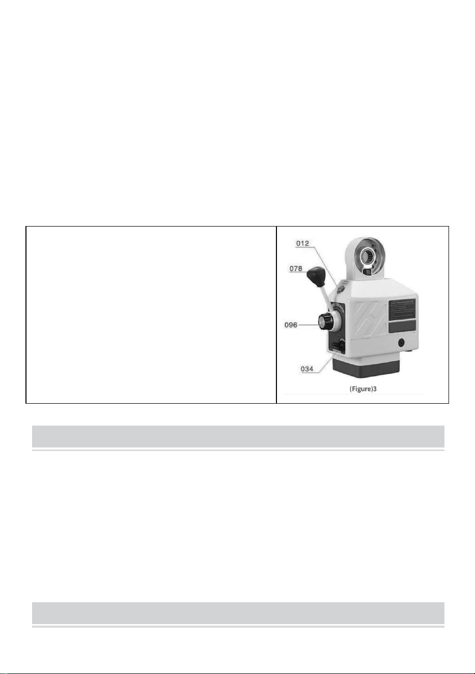
- 6 -
Steg 3: Vrid omkopplaren till läget "ON", sedan ska den optiska sändaren
(011) lysa
Steg 4: Vrid kontrollhandtaget (078) från mittläget till en riktning, så
kommer bordet att röra sig i samma riktning. Öka hastigheten medurs för
att styra vredet (096) och justera sedan arbetsbänken så att den rör sig
med en hastighet som gradvis ökar.
Steg 5: Om du vill ändra riktning på bordet, vrid omkopplaren för att hålla
handtaget i mittläget tills strömmen är avstängd. Vrid sedan kontrollspaken
i önskad riktning
(Se till att strömmen är avstängd innan du byter riktning)
LÄGGA MÄRKE TILL
1 . Hastigheten styrs av SPEED
KONTROLLERA VRED ASSY(B19).
Position "o" representerar" stopp" ang "g"
representerar den högsta hastigheten.
9. SNABBKOPPLINGSKNAPP (012) är för
snabb rörelse av bordet När den trycks
ned, då kommer bordet att röra sig i hög
hastighet.
PERIODIC MAINTENANCE
15. Rengör maskinen var 250:e timme, såsom rotorriktningsändring,
kolansamling och annat smuts inuti maskinen för att säkerställa isolering.
16. Smörjning, för in smörjoljan i växeln och smeta ut fettet på
grafitbasdrevet tänder
BRUSH POSITION
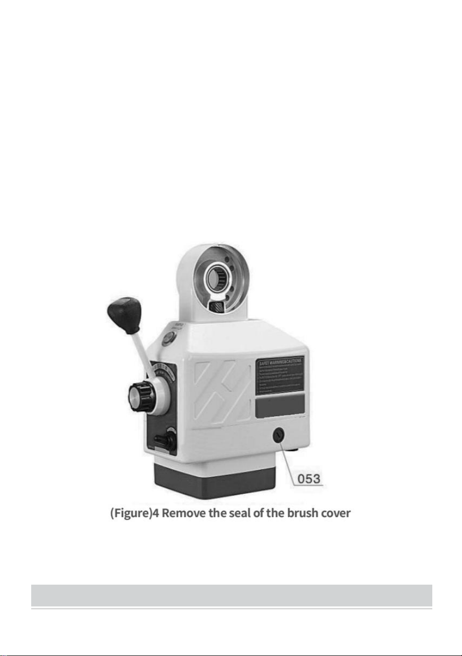
- 7 -
Steg 1: Ta bort borstlocket (053) (se figur 4). Då kan borsten (050) dyka
upp. Släpp inte borsten. Om borsten inte hoppar, ta försiktigt bort den med
spetsen på en skruvmejsel.
Steg 2: Kontrollera borstens konkava. Ytan ska vara slät och ren. Om du
märker stora repor på borsten, eller om delar av borsten har fallit av, eller
om den återstående längden på borsten endast är 6 mm, byt ut borsten
omedelbart mot en godkänd ersättningsborste. Om det bara är en smutsig
borste kan du torka av borsten med en penna och ett radergummi för att ta
bort eventuella kvardröjande fläckar från borsten.
Steg 3: Borsten har en fjäder och mässingsplugg. Vrid mässingspluggen
tills stiften är vertikala, tryck sedan in borsten i borsthållaren (052). Skruva
fast borstkåpan i borsthålet och dra åt.
PARTS LIST
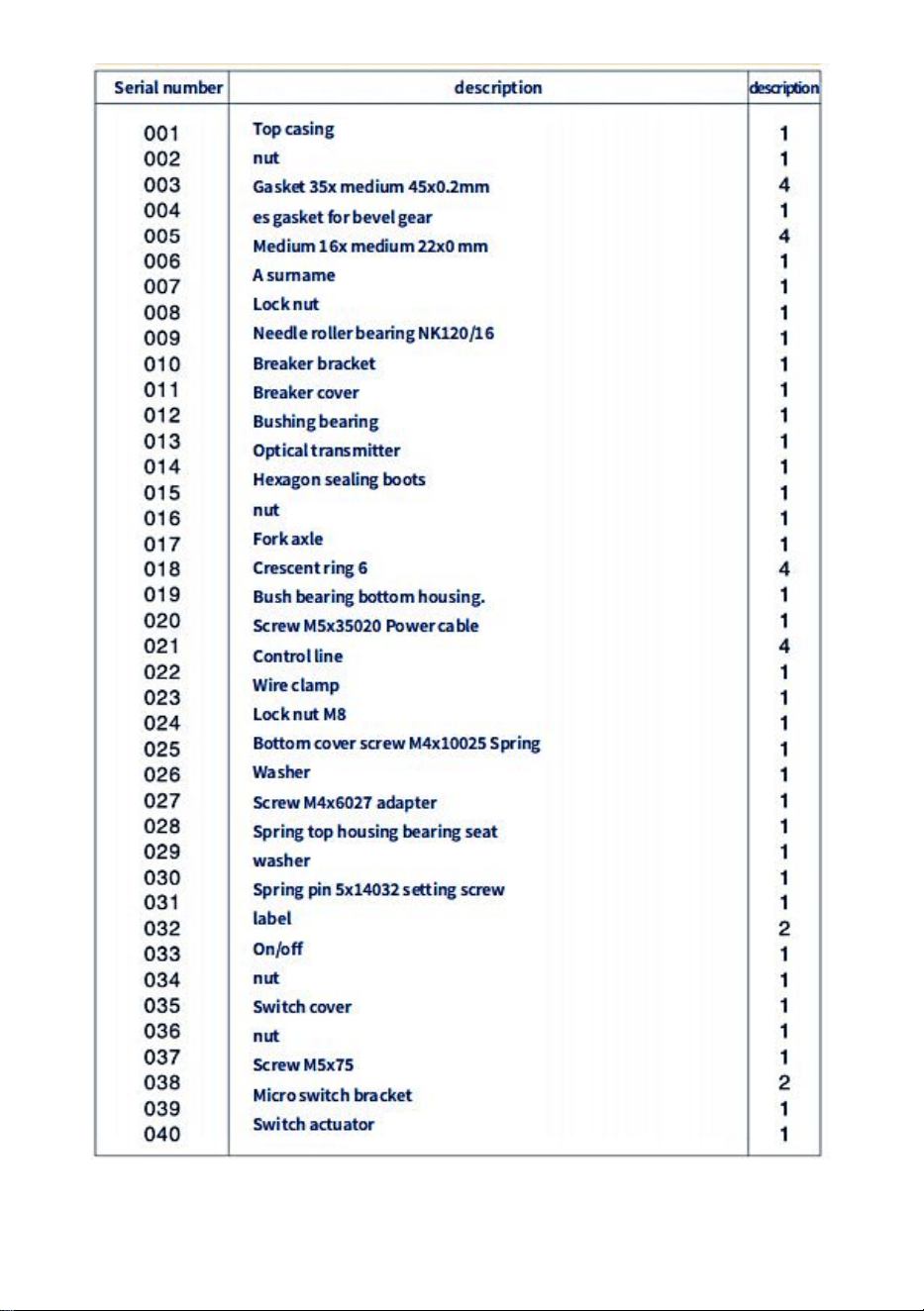
- 8 -

- 9 -
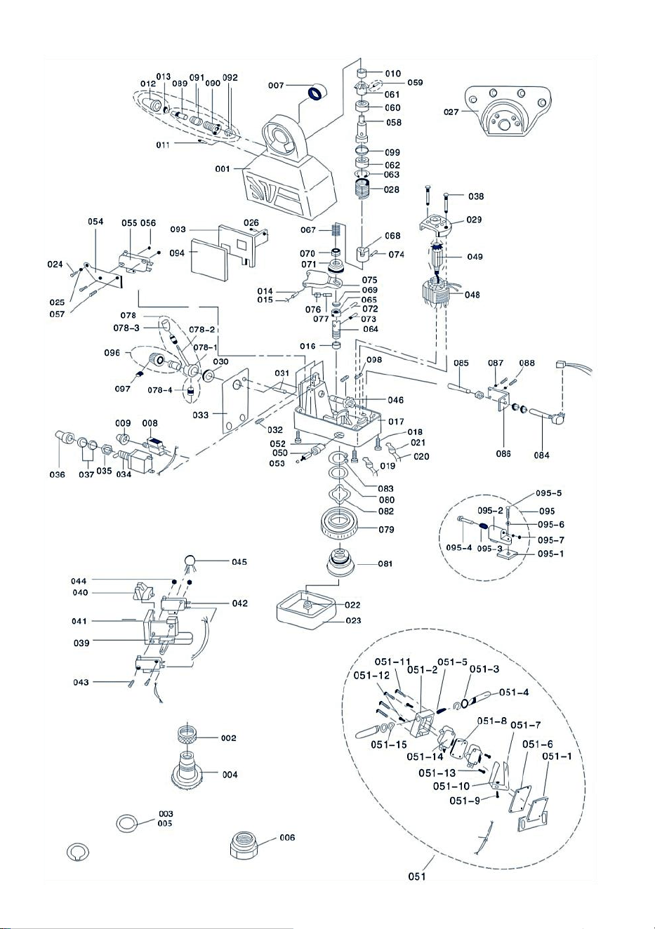
- 10 -
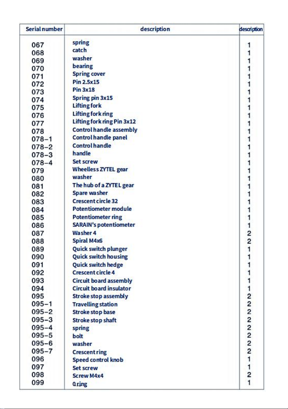
- 11 -

- 12 -
TROUBLESHOOTING
prob l em
Orsaker och lösningar
Det gör ljussändaren
inte avge ljus
1. Kraften matnings- eller kabelanslutningen är
felaktig
2. Strömbrytaren är skadad
3.Switch(034) är inte i läge "På" eller är
skadad.
4.Om motorn kan flyttas är den optiska sändaren
skadad
Motorn fungerar inte
(078) vänster eller höger
när kontrollhandtaget är
tryckt .
1. Motorn roterar när snabbknappen (012) trycks in
①varvtalsreglaget är det inte i "0"-positionen
②Potentiometer (084) fungerar inte korrekt
③Kretskortet (003) är skadat
2.Tryck på snabbknappen (012), motorn roterar inte
①borste och rotor kontakten är dålig eller borsten är
förbrukad krets in
②är trasig
beskrivning
1. Det finns en kortslutning mellan borsten (050) och
strömmatarlocket (017). Eller det finns en
kortslutning i gränslägesbrytaren (051)
2. Kolpulvret i kolborsten orsakar kortslutning.
Kan inte få hög hastighet
snabbhastighetsknapp när
tryckt (012)
Mikrobrytaren (055) under snabbknappen (012) är
det inte ansluten
Motorn fungerar inte
(078)vänster eller höger
när kontrollhandtaget är
nedtryckt
1. Snabbknappen (012) fungerar inte, och mikron
omkopplare (055) är ansluten.
2.Den kontrollerade likriktaren (BT141) på motstånd
(MYG14K)kiselkretskort är i kortslutningen
stat.
Bordet flyttades vid en
oöverträffad hastighet
Ledskruven på detta bord är inte tillräckligt bra.

- 13 -
CIRCUIT DIAGRAM
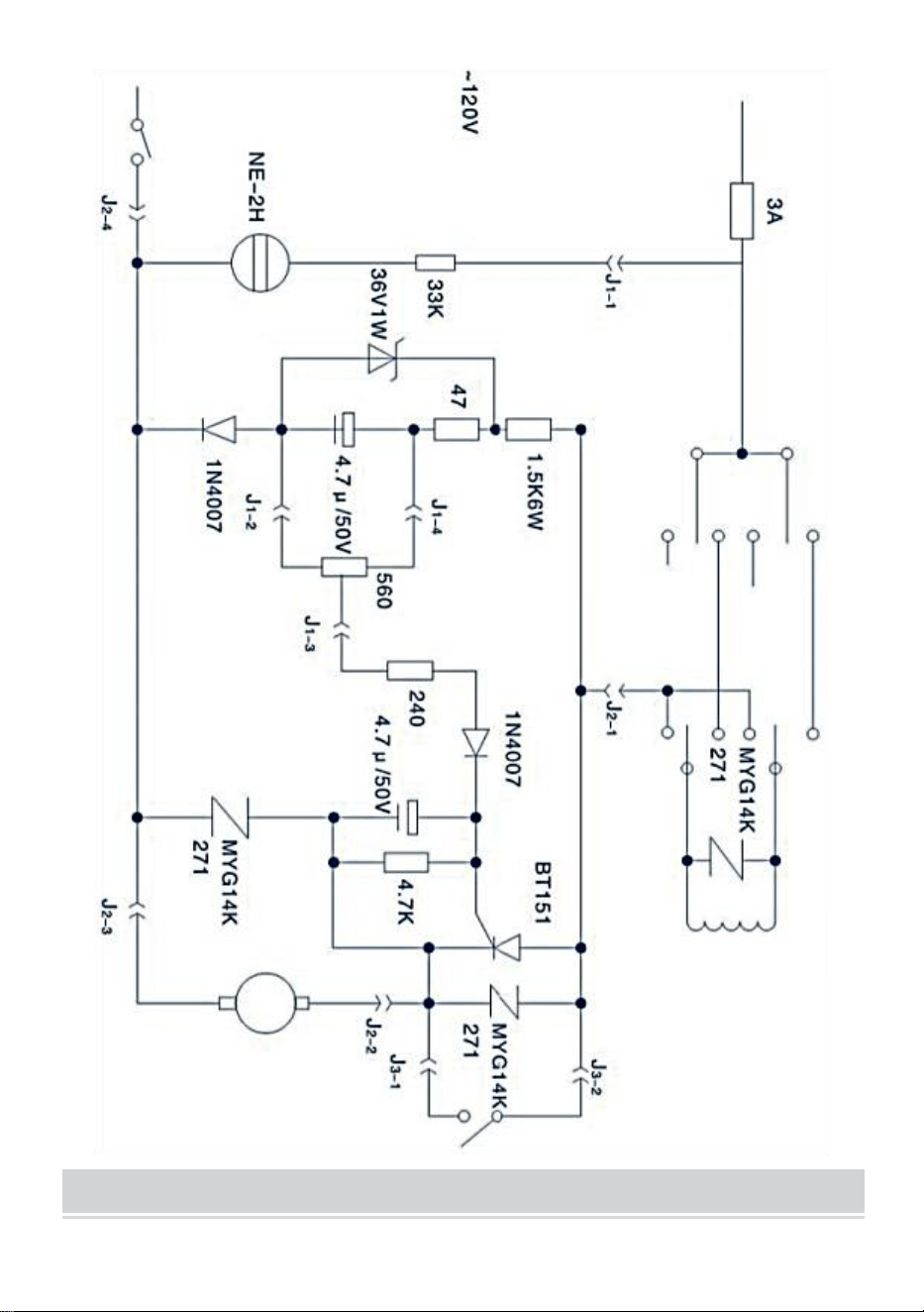
- 14 -
INSTRUCTIONS FOR INSTALLING CROSS FEEDS

- 15 -
Tvärgående ledarskruvar bör inte modifieras för idealisk installation
INSTALL T-SLOTS FOR TRANSVERSE FEED
HOW TO INSTALL KNEE LIFT FEED
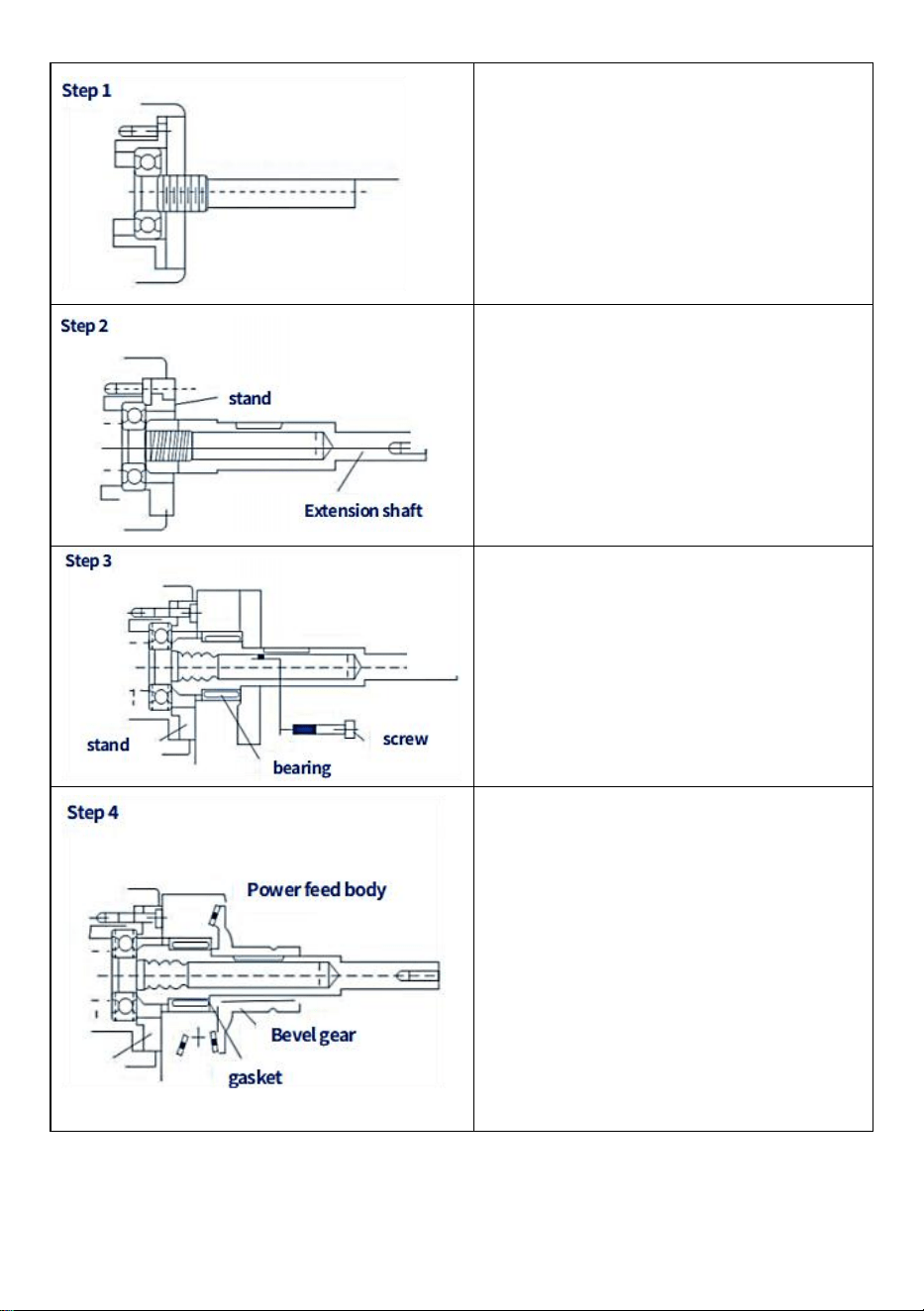
- 16 -
Ta bort handveven, ratten, rattens
lagerfläns och ·.... · Etc.
Montering av förlängningsaxel
Viktiga frågor:
(1) Axeländen måste vara nära lagrets
innerring
(2) Den inre axeln är 16 eller 18
gängad unc.
Dra åt stödet mot flänsen och dra
sedan åt knästödet på flänsen. Viktigt
är att den används för
vinkelpositionering.
Säkerhetsväxelns nyckel är inte isatt
Tryck och vrid det koniska kugghjulet
för hand för att kontrollera spelet.
(1) Om det behövs, lägg till några
distanser för att bli ordentligt glapp.
(2) Justera den främre kanten på
kugghjulet för att erhålla rätt spelrum
bak. Packa sedan om växeln med fett.
Sätt tillbaka växeln, tryck och vrid
sedan för att kontrollera spelet
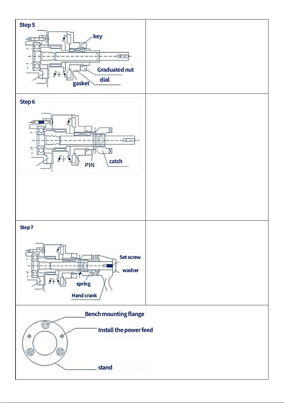
- 17 -
Efter att steg ( 4 ) är slutfört, ta bort det
koniska kugghjulet, installera sedan
nyckeln, byt ut växeln, installera
urtavlan, dra åt rattmuttern (lägg till
några små bitar av skivslipredskap).
Packa växeln med fett innan du
installerar den (använd inte silikonfett).
Installera kontrollstången på det
koniska kugghjulet och borra det i
hålet med en diameter på 5 mm. Kör
sedan fjäderstiftet.
En viktig Obs: Innan du installerar
fjäderstiftet, se till att du har utfört varje
steg noggrant och korrekt. Det
rekommenderas att installera en
manuell vev och vrida den medurs för
att kontrollera om det potentiella arket
är korrekt och om det finns en åtgärd
som har fastnat.
Montera fjäderveven (redan
installerad) och dra sedan åt brickan
och skruvarna . Det är viktigt att
smörja denna del och följa
instruktionerna för säker drift.
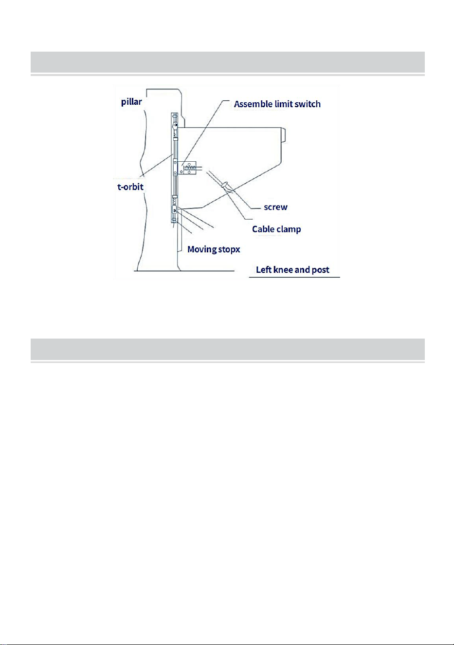
- 18 -
INSTALL T - RAIL LIFT FEED
ASSEMBLY - LIMIT ASSEMBLY INSTRUCTIONS

- 19 -
LONGITUDINAL FEED - HORIZONTAL ARRANGEMENT
hopsättning
1 . Flytta catwalken längst till vänster

- 20 -
2. Ta bort handveven, ratten och lagerflänsen från banan.
3. Montera vid behov förlängningsaxel för T-bord och montera drivningen
redskap.
4. Ta bort de två skruvarna (M8 x 25) från den lilla adaptern.
5. Installera strömmataren horisontellt på den stora adaptern.
6. Justera växlarnas läge och spelrum
7. Dra åt skruvarna på drivhjulet.
8. Dra åt de två skruvarna på den lilla adaptern (2-M8x25)
9. Sätt lite grafitfett på tänderna på transmissionsväxeln
Sanven Technology Ltd.
Adress: Suite 250, 9166 Anaheim Place, Rancho Cucamonga, CA
91730
Tillverkad i Kina