CRY2833 & CRY2834
Sound Level Meters
User Manual
2
Warranty Statement
We proudly offer a two-year warranty on the CRY2833 &
CRY2834 Sound Level Meters, ensuring it meets the highest
standards of quality and performance. This warranty covers
defects in materials and workmanship under normal use.
Coverage Details:
• Warranty Period: Two years from the date of purchase.
• What’s Covered: Defects in materials or workmanship that
occur under normal use.
• What’s Not Covered: Damage caused by misuse,
unauthorized modifications, accidents, or external factors.
To request a warranty service, please contact our customer
support team with your proof of purchase. We will repair or
replace the device at our discretion.

3
Contact Us
Hangzhou Headquarters
Tel: +86-571-88225128
E-mail: [email protected]m
Add: No. 10 Xianqiao Rd, Yuhang Dist, Hangzhou, China
Web: www.crysound.com
U.S. Office
Add: 515 S Fry Rd, Suite A-221, Katy, TX 77450, USA
Tel: +1-877-215-7752
4
Safety Use Instructions
To prevent possible fire or personal injury:
Please read the contents of this safety notice carefully before using the
product.
Use the product only for its intended purpose.
Unauthorized opening of the unit will void the warranty. Contact
CRYSOUND for more information.
Stop using the device if it malfunctions or heats up abnormally.
Please contact the manufacturer for equipment repair work.
Do not store the equipment near heat sources, flames or in a hot
environment.
If the storage time is longer than 1 month, please store the product at
an ambient temperature of less than 40 ℃ / 140 ℉.
5
FCC Warning
This device complies with part 15 of the FCC Rules. Operation is subject to the
following two conditions:
(1) this device may not cause harmful interference, and (2) this device must accept
any interference received, including interference that may cause undesired operation.
This equipment has been tested and found to comply with the limits for a Class B
digital device, pursuant to part 15 of the FCC Rules. These limits are designed to
provide reasonable protection against harmful interference in a residential installation.
This equipment generates, uses and can radiate radio frequency energy and, if not
installed and used in accordance with the instructions, may cause harmful interference
to radio communications. However, there is no guarantee that interference will not
occur in a particular installation. If this equipment does cause harmful interference to
radio or television reception, which can be determined by turning the equipment off
and on, the user is encouraged to try to correct the interference by one or more of the
following measures:
—Reorient or relocate the receiving antenna.
—Increase the separation between the equipment and receiver.
—Connect the equipment into an outlet on a circuit different from that to which the
receiver is connected.
—Consult the dealer or an experienced radio/TV technician for help.
Any changes or modifications not expressly approved by the party responsible for
compliance could void the user's authority to operate the equipment.

6
FCC WARNING
This equipment complies with FCC radiation exposure limits set forth for an uncontrolled environment.
End user must follow the specific operating instructions for satisfying RF exposure compliance. This
transmitter must not be co-located or operating in conjunction with any other antenna or transmitter.
The mobile device is designed to meet the requirements for exposure to radio waves established by the
Federal Communications Commission (USA). These requirements set a SAR limit of 1.6 W/kg averaged
over one gram of tissue. The highest SAR value reported under this standard during product certification
for use when properly worn on the body is 0.204W/kg.
For body operation, this device has been tested and meets FCC RF exposure guidelines when used with
any accessory that contains no metal and that positions a minimum of 0mm from the body. Use of other
accessories may not ensure compliance with FCC RF exposure guidelines.

7
Catalog
1 Introduction..................................................................................................................10
1.1 About This Manual.........................................................................................10
1.2 About the CRY2833 & CRY2834...............................................................10
2 Technical Specifications...........................................................................................11
3 Instructions For Use.................................................................................................. 13
3.1 Icon and Interface Illustration....................................................................13
3.2 Preparations.....................................................................................................14
3.3 Power On.......................................................................................................... 15
3.4 Settings..............................................................................................................15
3.4.1 WiFi.........................................................................................................16
3.4.2 Bluetooth®............................................................................................16
3.4.3 Analog Output.................................................................................... 17
3.4.4 Display Settings..................................................................................19
3.4.5 Storage..................................................................................................19
3.4.6 Date & Time......................................................................................... 19
3.4.7 Language..............................................................................................20
3.4.8 About......................................................................................................20
3.5 Calibration........................................................................................................ 22
3.6 Measurement Parameters...........................................................................23
3.7 Use of the Testing App................................................................................ 23
3.7.1 Parameter Interface.......................................................................... 24

8
3.7.2 Data........................................................................................................ 26
3.7.3 Record....................................................................................................26
3.7.4 Printer.................................................................................................... 27
3.8 Use of the OCT App...................................................................................... 28
3.8.1 Parameter Interface.......................................................................... 28
3.8.2 Settings................................................................................................. 28
4 Remote Control...........................................................................................................29
4.1 Serial Communication Parameters...........................................................29
4.2 Protocol Formatted Instructions...............................................................29
4.3 CRY2833 & CRY2834 Register Definitions............................................29
4.4 CRY2830 Monitoring Series SPL Data Analysis...................................31
4.5 CRY2833 & CRY2834 Communication Example................................. 32
Appendix A: Table of Measured Values.................................................................... 35
Appendix B: CRY333 Typical Frequency Response (0° Incidence Angle).... 36
Appendix C: CRY331 Typical Frequency Response (0° Incidence Angle).... 37
Appendix D: Impact of Extension Cable................................................................... 38
Appendix E: The Usage Instructions for the Bluetooth® Printer...................... 39
9
Revision History
Revision number
Description
Revision date
1.0
Initial version
2025/08/10

10
1 Introduction
1.1 About This Manual
This user manual describes the CRY2833 & CRY2834 Sound Level
Meters and is divided into the following sections:
Introduction
Technical Specifications
Instructions For Use
Appendix
1.2 About the CRY2833 & CRY2834
CRY2833 & CRY2834 sound level meters meet the stringent
requirements of Class 1 and Class 2 ensuring accurate and reliable
acoustic measurements. Functions such as statistical analysis, data
logging, wireless control and transmission are included.
The CRY2833 & CRY2834 sound level meters' design balances esthetics
and ergonomics. They feature a 2.8 inch high-resolution, color TFT
display and simple ergonomic controls. Data can be stored on an
internal microSD memory card for easy transfer to external analysis
systems.

11
2 Technical Specifications
Technical Specifications
Type
CRY2834
CRY2833
Microphone
CRY331 (-28±2 dBV/Pa)
CRY333 (-26±2 dBV/Pa)
Pre-amplifier
CRY2830PA-1
Linear Range
@ 1 kHz: 25-140 dBA
@ 31.5 Hz: 25-101 dBA
@ 4k Hz: 25-141 dBA
@ 8k Hz: 25-138 dBA
@ 12.5k Hz: 25-133 dBA
@ 1 kHz: 25-140 dBA
@ 16 Hz: 25-83 dBA
@ 31.5 Hz: 25-101 dBA
@ 4k Hz: 25-141 dBA
@ 8k Hz: 25-138 dBA
@ 12.5k Hz: 25-133 dBA
@ 16k Hz: 25-127 dBA
Time Weighting
F, S, I
Frequency Weighting
A, C, Z
Sampling Rate
48k Hz
A/D Resolution
24 - bit
Frequency Range
20 Hz - 12.5k Hz
10 Hz - 20k Hz
Applicable Standards
IEC 61672-1:2013 Class 2
IEC 61672-1:2013 Class 1
Measuring Parameter
Lp, Leq,t, Lpeak, Leq,T, Lmax, Lmin, LN (N=5, 10, 50, 90,
95), SD
12
Measurement Function
Integrating, Statistical Analysis, 1/1 Oct, 1/3 Oct
Display
320 × 240 TFT Display
Battery
4 × AA
Operating Time
24 hours (Screen off)
Interface
AC/DC, USB-C, RS232, BT/WiFi
Memory
32 GB microSD card
Reference Level
94dB @ 1k Hz / 114dB @ 1k Hz
Calibration
Sound Calibrator Class 1 or Class 2
External Power Supply
5V DC, 5V USB-C, 4 × AA battery
Operating Temperature
Range
-20 to +60 ℃
Humidity Range
≤ 90% RH
Weight
330 g
Size
L × W × H = 249 × 76 × 30.5mm
Operation
Button
Note:
1 Please do not use an external power supply exceeding 6 V, as it may
damage the equipment.
2 If you need the timekeeping function when power off, please install a
CR2016 button battery.
13
3 Instructions For Use
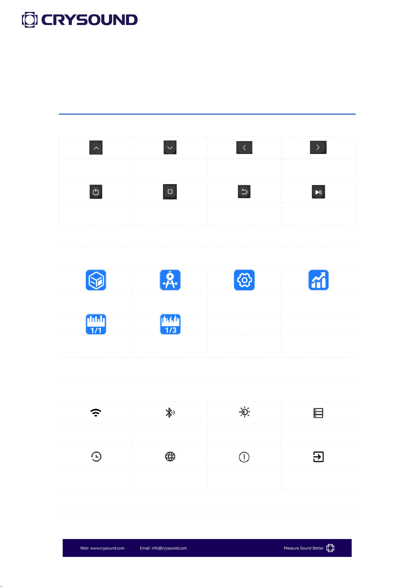
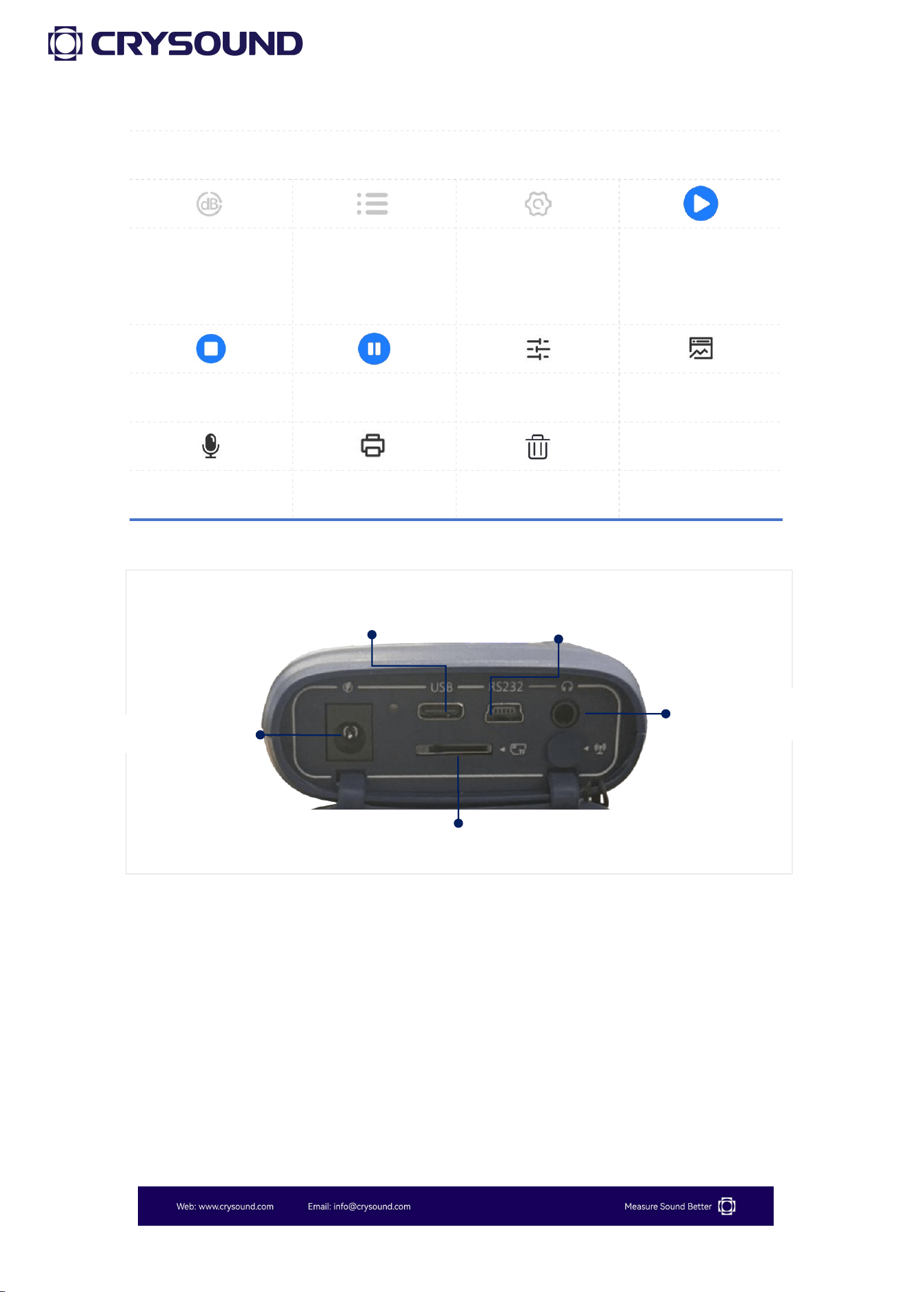
3.1 Icon and Interface Illustration
Button
Arrow Key (up)
Arrow Key (down)
Arrow Key (left)
Arrow Key (right)
Power Key
Confirm Key
Return Key
Recording Key
Main Interface
SLM APP
Calibration APP
Settings APP
Statistics APP
1/1 OCT APP
、1/3 OCT APP
、
、
Settings
WiFi
Bluetooth
Display Settings
Storage
Date & Time
Language
About
Analog Output
14
Function App
Main Interface
Secondary
Interface
Settings
Start Test
Testing
Pause Test
Mode Settings
Data
Record
Print
Delete
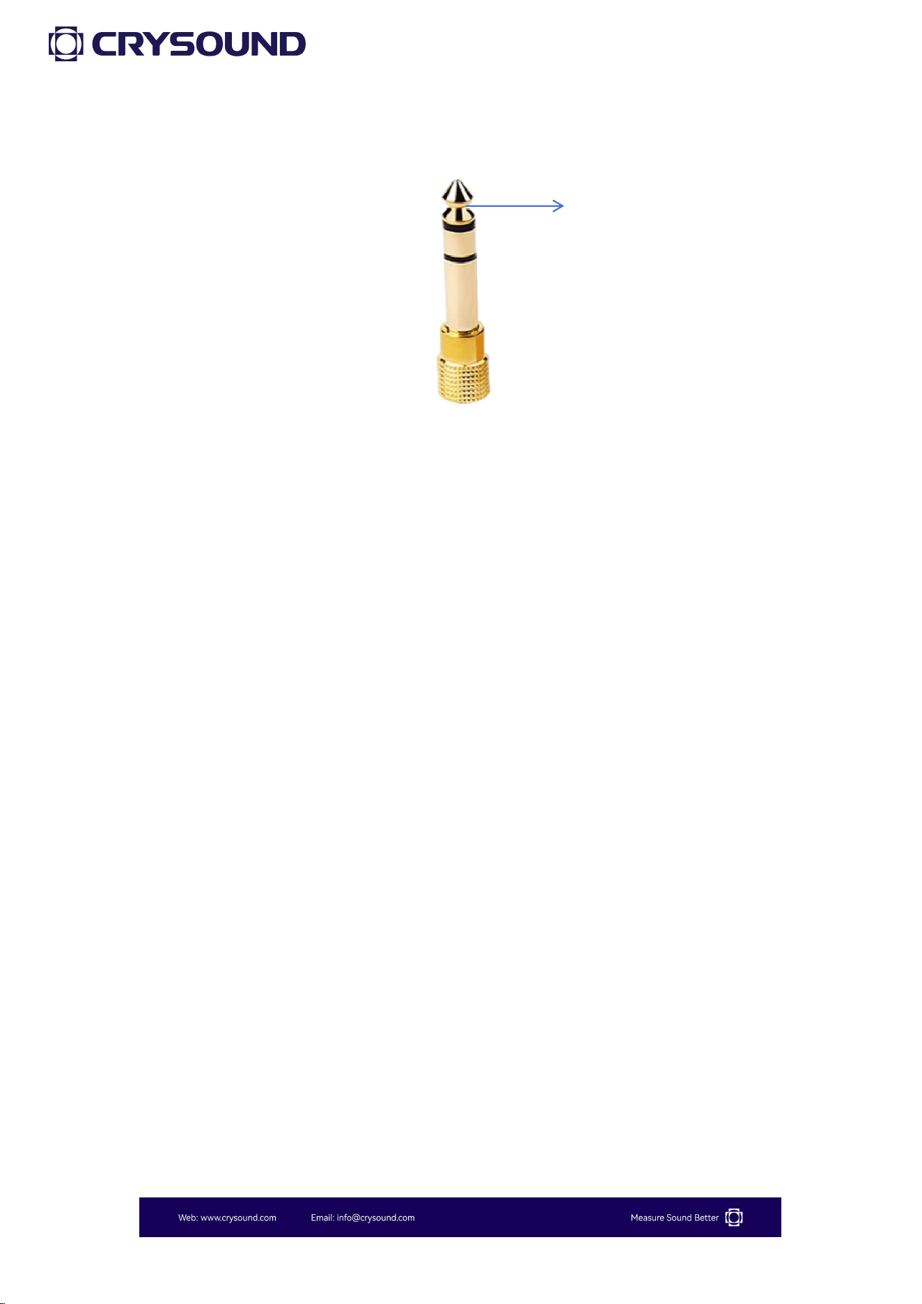
3.2 Preparations
1) Check whether the microphone and the preamplifier are properly
installed.
2) Check whether the battery is sufficiently charged.
3) If necessary, use a sound calibrator to calibrate the sound level meter
before using.
DC Power Supply
USB-C Power Supply
MicroSD Card Slot
Heaphone Monitoring
RS232 communication Port
15
4) The sound level meter should be regularly (e.g., once a year) sent to
a calibration department for verification to ensure its accuracy.
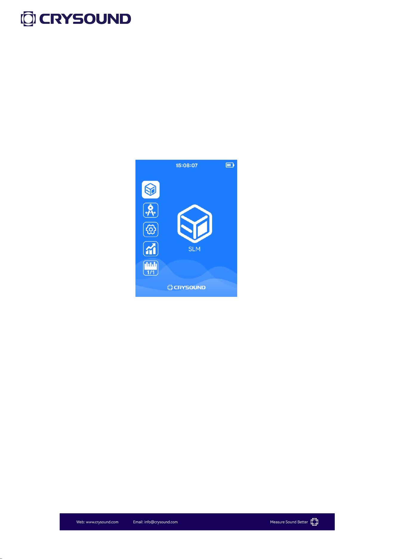
3.3 Power On
1) Before official use, install four new AA batteries to ensure the device
operates normally during measurements.
2) Press the power button for 3 to 5 seconds until the startup animation
appears on the screen. The screen will then display the measurement
main interface.
3.4 Settings
From the main interface screen, simply press the "Confirm" button to
enter the "Settings" screen.
For the Bluetooth and WiFi version, the Settings provides access to
WiFi connection, Bluetooth® connection, analog output, display
settings, storage, date & time, language settings and device
information.
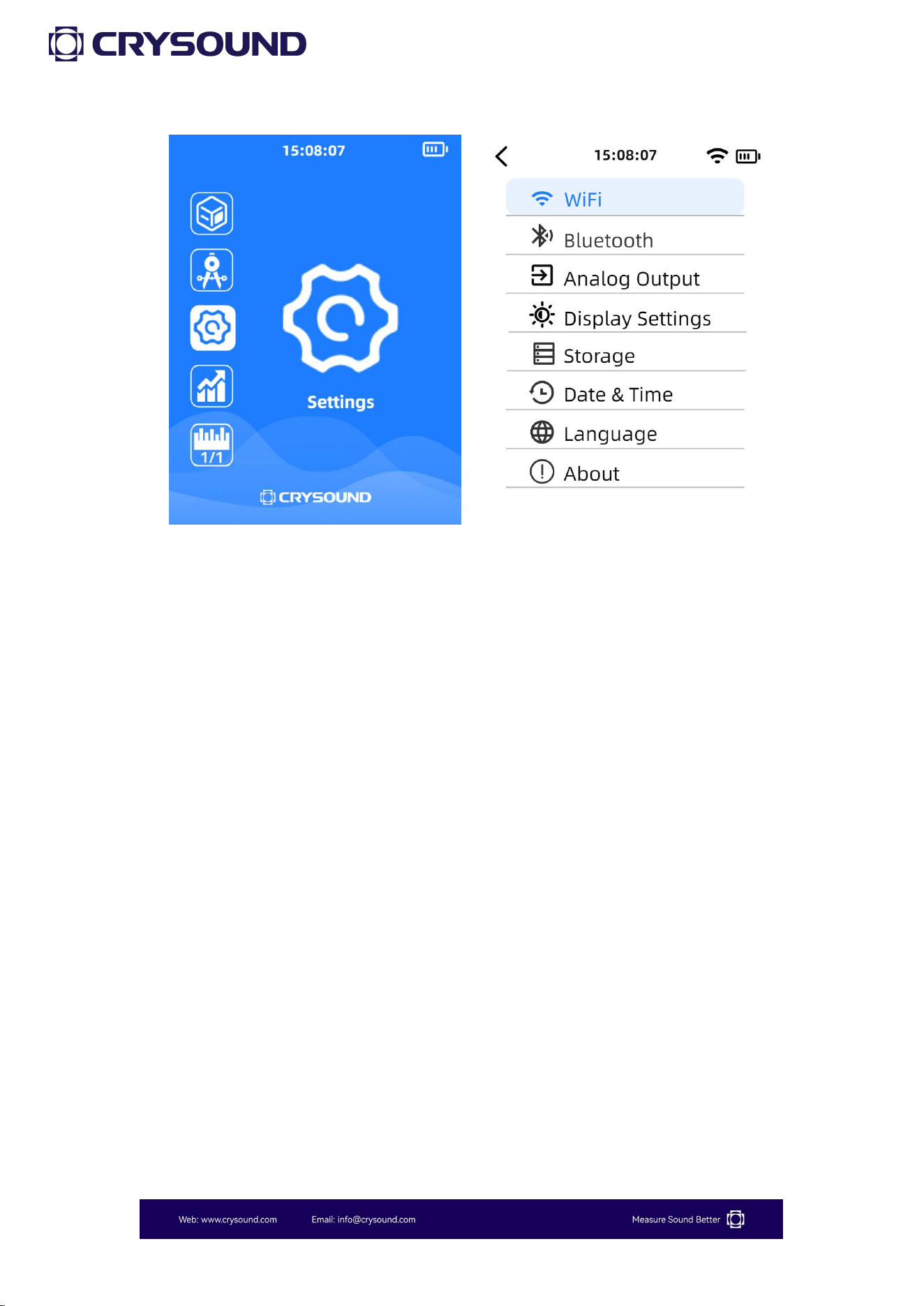
16
3.4.1 WiFi
Users can use the button to turn on WiFi , and the bottom of the screen
will display the detected WiFi networks. After selecting the desired WiFi
network, press the "Confirm" button to enter the password. Once
connected successfully, the screen will show the connected WiFi
network.
3.4.2 Bluetooth®
Users can use the button to turn on Bluetooth®, and the bottom of the
screen will display the detected Bluetooth devices. After selecting the
desired device, press the "Confirm" button. Once the connection is
successful, the screen will show the connected Bluetooth device.
17
A typical application for Bluetooth is to connect to a Bluetooth printer
for data printing.
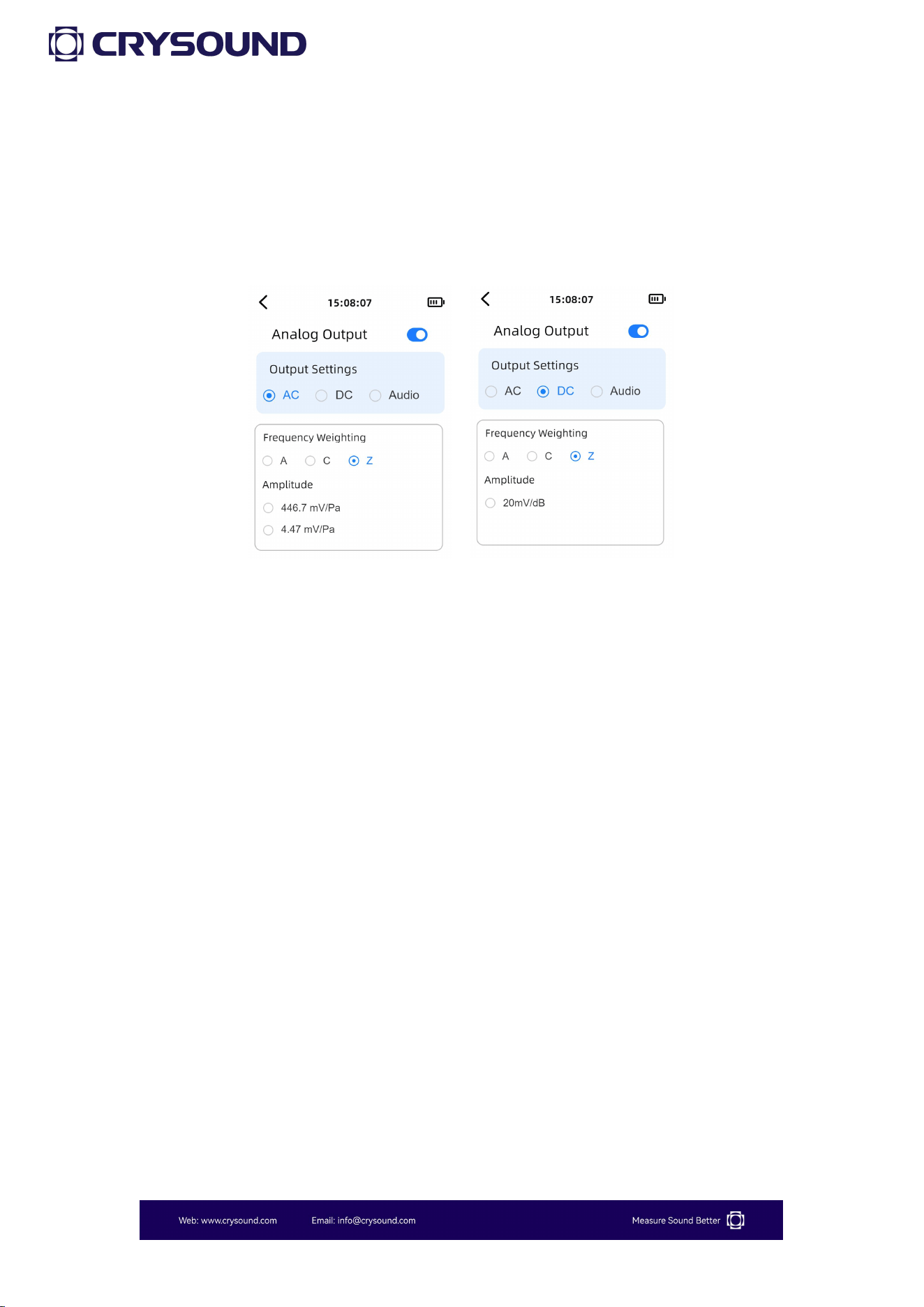
3.4.3 Analog Output
When "Analog Output" is selected by the cursor, pressing the confirm
button enters the Analog Output interface.
By default, the cursor is focused on the switch row. The user can press
the Confirm button to toggle the Analog Output function ON or OFF.
The currently available Analog Output options are "AC", "DC", and
"Audio".
The headphone output channel configuration is as follows:
18
When "AC" is selected, users may choose A, C, or Z weighting and select
between 446.7 mV/Pa or 4.47 mV/Pa amplitude ranges; upon enabling
this function, a 1 kHz AC signal scaled according to the selected
weighted sound pressure level will be output through the bottom
connector.
When "DC" is selected, A, C, or Z weighting options are available, and
enabling the function outputs a DC signal similarly scaled based on the
chosen weighted sound pressure level.
When "Audio" is selected, gain adjustment becomes configurable
according to input signal amplitude, and activation outputs the raw
audio signal with specified gain through the bottom connector.
Left Channel Output
19
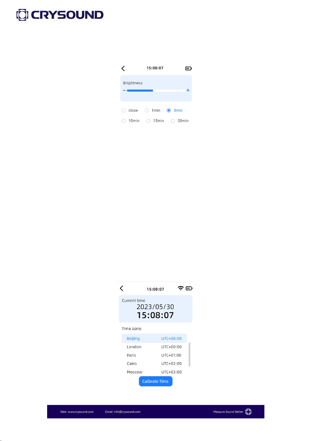
3.4.4 Display Settings
In the "Display Settings", users can adjust the screen brightness using
the left and right buttons, and set the screen timeout below. The device
defaults to 50% brightness and does not automatically turn off the
screen.
3.4.5 Storage
Users can view the microSD card usage status on this screen.
3.4.6 Date & Time
20
3.4.7 Language
In the "Language" section, users can switch between Chinese and
English.
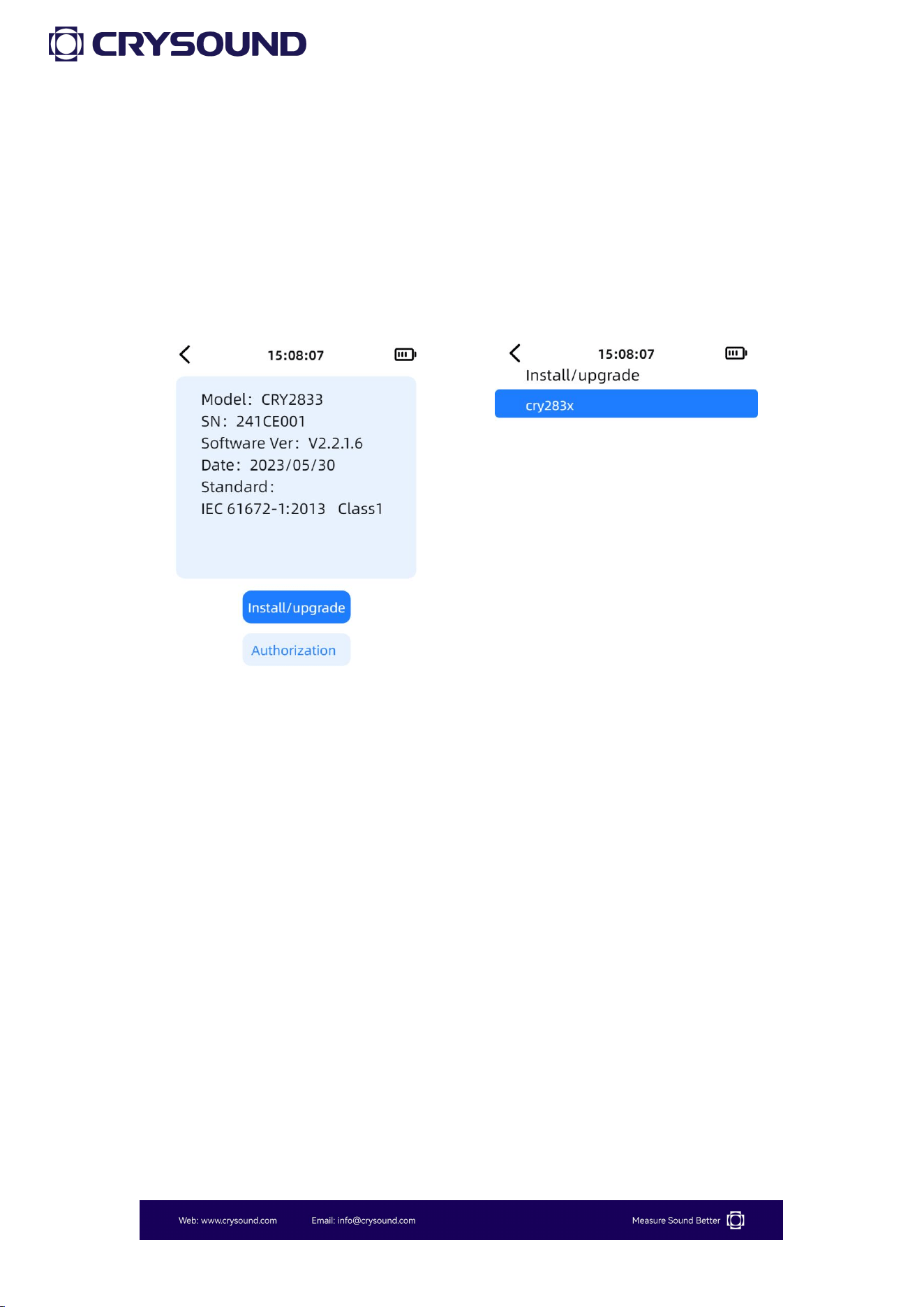
3.4.8 About
In the "About" section, users can view device information, as well as
perform authorization and upgrade operations.
3.4.9.1 Installation/Upgrade
How to download upgrade file
1- Insert the microSD card into the computer and create a folder
named "update" in the root directory of the microSD card.
2- Extract the upgrade bin file and place it in the "cry283x" folder
within the "update" folder.
How to
upgra
de
1- Insert the microSD card while the device is powered off, then turn

21
on the device.
2- Go to "Settings" - "About" and click the "Installl/upgrade" button.
3- Select the corresponding installation package cry283x for
installation. Please ensure the device has sufficient power during the
installation process and do not perform any other operations.
3.4.9.2 Authorizaition
On this interface, users can view the current authorization status of the
device. If you need to add authorization, please contact customer
support.
22
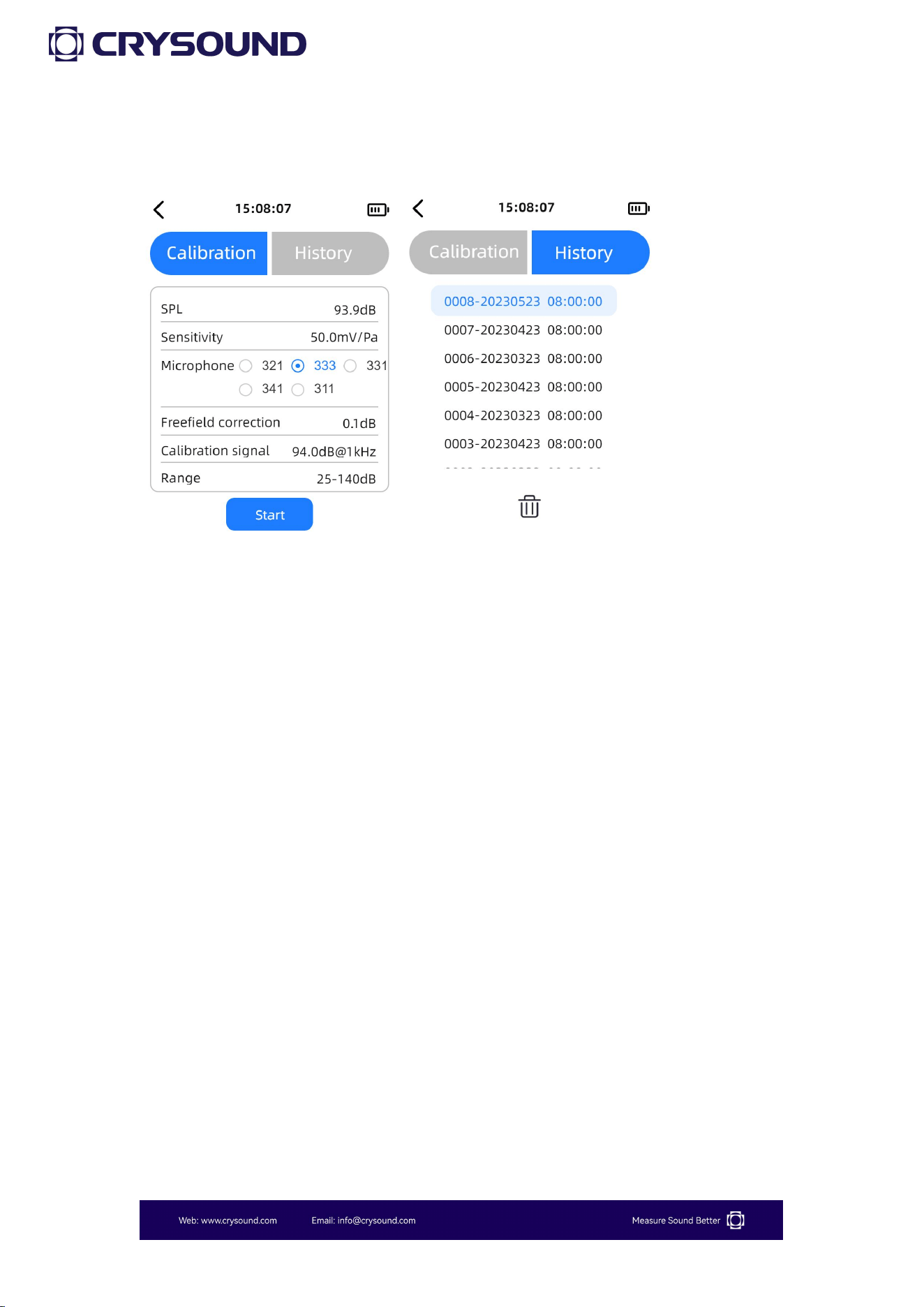
3.5 Calibration
Users can click "Calibration" to enter the "Calibration" app. The "Calibration"
interface displays the current sound pressure level and the microphone
sensitivity. Users can set the microphone model, and the corresponding
free-field correction value will change accordingly, with CRY2834 defaulting
to the CRY331 sensor and CRY2833 defaulting to the CRY333 sensor.
Users can select from four different calibration signals. When the calibrator
is connected and producing a stable sound, users can press "Start" to begin
calibration. After calibration, the sensitivity will automatically update. If
there are significant fluctuations in the sound signal during calibration, it
may fail. We recommend to use a 114dB sound source in high background
noise conditions for calibration.
Users can view the "Calibration History" in the "History" section and can
select specific calibration records for deletion.
23
3.6 Measurement Parameters
Parameters
SLM (Basic)
SLM
Statistics
1/1 OCT
1/3 OCT
Lp, Lmax,
Lpeak
■
■
■
Leq, Lmin
■
■
LN (N=5、
10、50、90、
95),SD
■
1/1 OCT
■
1/3 OCT
■
3.7 Use of the Testing App
The use of the SLM and statistics app on the sound level meter is quite
similar.
Below are the instructions for usage.
24
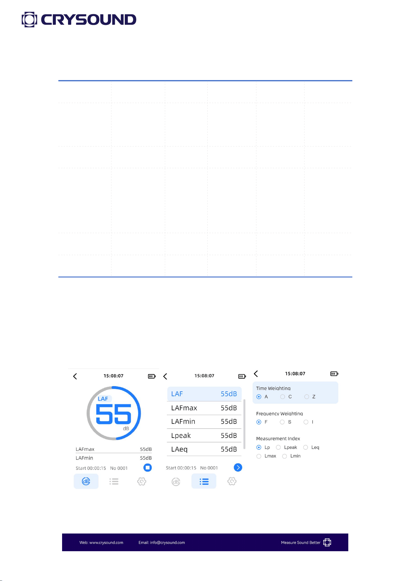
3.7.1 Parameter Interface
The sound level meter contains two measurement parameter interfaces,
where users can set 3 or 5 test parameters on each interface. By
clicking on a test parameter, users can enter the parameter selection
and return to the parameter interface.
Users can click the "Test" button to start testing. During the test, a long
press on the "Test" button will pause the test, while a short press will
stop the test.
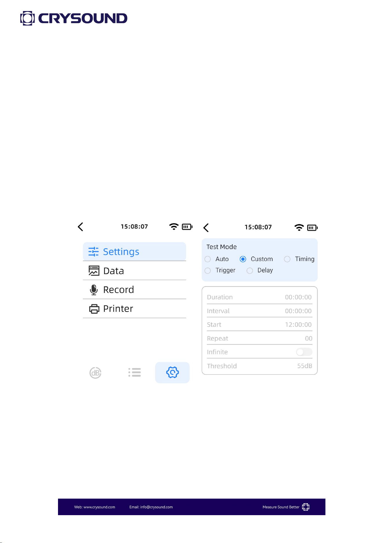
When users switch to the "Settings" interface, they can configure the
test mode, view data playback, set recording options, and choose
printing methods.
In the "Test Mode" settings, users can select from "Auto" , "Custom" ,
"Timing", "Trigger", and "Delay" test modes. The meanings of each test

25
mode are as follows:
① Auto: Test duration, test interval and repetition times can be set.
After pressing the start measurement button, the test will be
conducted according to the set test parameters and stored
automatically.
② Custom: Manually start a measurement and manually stop the
measurement in the main interface operation button area.
③ Timing: You can set the test duration and start test time in the
setting interface, and when it reaches the start test time, it will
automatically start measuring and stop after reaching the test duration.
④ Trigger: The test duration and threshold value can be set in the
setting interface. When the LAF reaches the set threshold value, the
test will start automatically and the test time will be the test duration
set by the user.
⑤Delay: Users can set the duration for the delay. After pressing the
test button, the device will not start testing immediately but will begin
after the specified delay duration.

26
3.7.2 Data
Users can click on "Data" to enter the data viewing list.
When the microSD card is inserted, the test data will be automatically
saved to the microSD card. Users can find the corresponding test data
files based on the test time, and click to review the data .
This feature only supports viewing the last second of data for all data
displayed in the list. If you need to view all parameters during the test,
you can insert the microSD card into the computer to view the CSV
data file.
3.7.3 Record

27
Users can click on "Record" to enter the recording settings interface.
Press the "Confirm" button to control the start and stop of recording.
This device supports two recording modes: automatic(auto) and
triggered. Below is an explanation of the two recording modes:
Auto: Start recording as soon as you start the test, no need to set the
recording duration.
Trigger: you can set the recording duration as needed, when the LAF
reaches the set threshold, it will automatically start recording, and the
test time will be the recording duration set by the user.
3.7.4 Printer
Users can click on "Print" to enter the print settings interface.
This device supports two printing methods: "Bluetooth®" and "RS232",
and supports two print formats: "Brief" and "Detailed".
The usage instructions for the optional Bluetooth® printer can be found
in Appendix E.
28
3.8 Use of the OCT App
1/1 OCT and 1/3 OCT measurement operation is similar to total value
integration and can refer to 3.6. Below is an introduction to the interface
display.
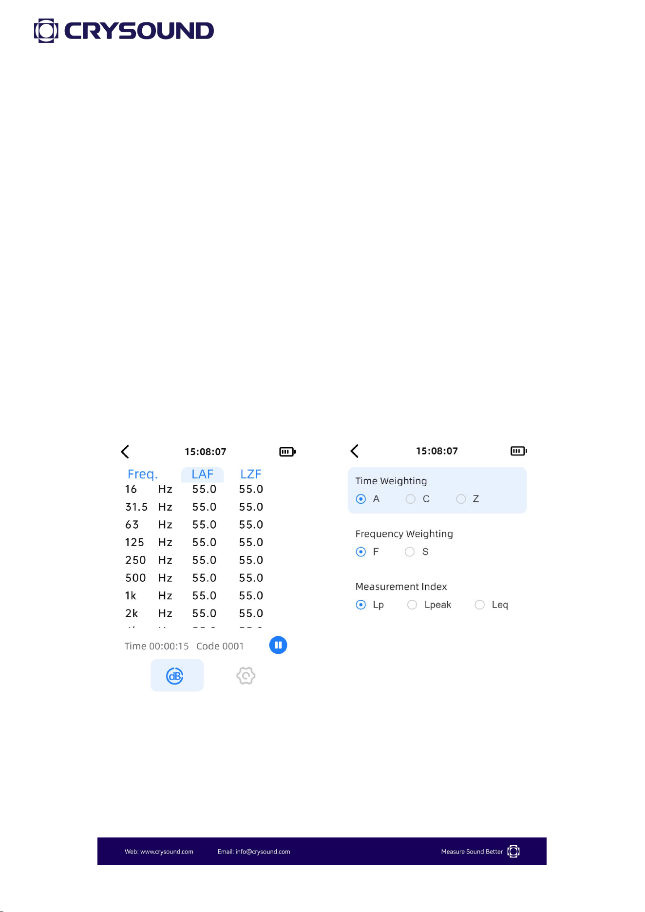
3.8.1 Parameter Interface
As shown in the figure, this is the display interface for the octave band.
Once entered, users can select measurement parameters and display
frequencies using the up and down keys. The left and right keys are
used to switch between the measurement interface and the settings
interface.
3.8.2 Settings
Users can enter the "Settings" interface by using the left and right
arrow keys. For detailed operations, please refer to section 3.6.

29
4 Remote Control
CRY2833 & CRY2834 sound level meters support remote control via
RS232 serial port. Users can control the device using the included
RS232 to DB9 communication cable.
4.1 Serial Communication Parameters
4.2 Protocol Formatted Instructions
The following is for reference.
Slave Address
Function Code
Data
CRC
The slave address length is 1 byte, used in communication to
distinguish between different devices on the bus. The CRY2830 sound
level meter is defaulted to 01 as a placeholder.
4.3 CRY2833 & CRY2834 Register Definitions
The device parameters are stored in holding registers and can be read
using function code 03.
The function code length is 1 byte, as illustrated in the following
diagram:
Baud Rate
115200
Data Bits
8 bits
Parity Bit
None
Stop Bits
1 bit
Data Format
HEX

30
Function Code
Function Introduction
03
Read holding register
04
Read input register
06
Write single register
10
Write multiple registers
The data length is multi-byte, and its composition format is as follows:
APP Function Reigister + Starting Address + Number of Registers to
Read/Write + Data.
The various APP function codes are as follows:
APP Function Registers
Address
0x00
0x02
0x03
Definition
Main Menu, Settings App,
Calibration App
SLM
Statistics
Address
0x04
0x05
0x06
Definition
SPL
1/1 OCT
1/3 OCT
The holding registers are as follows:
Function Registers
Address
Data Content
Notes
0x00
0x16
SN
0x00
0x20
Address

31
The status register information is as follow:
Function
Registers
Address
Data Content
Notes
0x02
0x03
0x05
0x06
0x03
Testing status
00 00 Stop testing
00 01 Start testing
00 02 Pause testing
00 03 Resume testing
4.4 CRY2830 Monitoring Series SPL Data Analysis
Input Register
High 8 bits
Low 8 bits
Definition
High 8 bits of SPL data
Low 8 bits of SPL data
SPL conversion formula:
SPL = (HiByte * 256 + LowByte) / 10
Example:
For the return value 01 8E, the corresponding sound pressure level is
(1*256+8*16+14*1)/10=39.8 dB.
32
4.5 CRY2833 & CRY2834 Communication Example
Example 1: Control the SLM app to start the testing
Master Sends: 01 06 02 03 00 01 B9 B2
Send Data
HEX
Note
Slave Address
01
Address
Function Code
06
Write single register
High 8 Bits of Register Address
02
SLM APP
Low 8 Bits of Register Address
03
Testing status register
High 8 Bits of Number of Registers
00
Low 8 Bits of Number of Registers
01
Start testing
Low 8 Bits of CRC Checksum
B9
High 8 Bits of CRC Checksum
B2
Example 2: Control the SLM app to stop the testing
Master Sends: 01 06 02 03 00 00 78 72
Send Data
HEX
Note
Slave Address
01
Address
Function Code
06
Write single register
High 8 Bits of Register Address
02
SLM APP
Low 8 Bits of Register Address
03
Testing status register
High 8 Bits of Number of Registers
00
Low 8 Bits of Number of Registers
00
Stop testing
33
Low 8 Bits of CRC Checksum
78
High 8 Bits of CRC Checksum
72
Slave Response: 01 10 02 E1 02 18 02 02 02 11 02 22 02 A1 02 B7 02 89 72
B3
Send Data
HEX
Note
Slave Address
01
Function Code
10
High 8 Bits of Register Address
02
SPL1
Low 8 Bits of Register Address
E1
High 8 Bits of Register Address
02
SPL2
Low 8 Bits of Register Address
18
High 8 Bits of Register Address
02
SPL3
Low 8 Bits of Register Address
02
High 8 Bits of Register Address
02
SPL4
Low 8 Bits of Register Address
11
High 8 Bits of Register Address
02
SPL5
Low 8 Bits of Register Address
22
High 8 Bits of Register Address
02
SPL6
Low 8 Bits of Register Address
A1
High 8 Bits of Register Address
02
SPL7
Low 8 Bits of Register Address
B7

34
High 8 Bits of Register Address
02
SPL8
Low 8 Bits of Register Address
89
Low 8 Bits of CRC Checksum
72
High 8 Bits of CRC Checksum
B3
Note: In manual mode, when the stop test command is sent, the device will
return the eight parameters displayed on the measurement interface. In
automatic mode, after reaching the test end status, the device will also
automatically return to the measurement interface to display the eight
parameters.
Example 3: Underrange status return
Slave Response: 01 04 02 03 02 00 01 13 C0
Send Data
HEX
Note
Slave Address
01
Address
Function Code
04
Read single register
High 8 Bits of Register Address
02
SLM APP
Low 8 Bits of Register Address
03
Testing status register
Return Byte
02
High 8 Bits of Number of Registers
00
Low 8 Bits of Number of Registers
01
01 Underrange 02 Overload
Low 8 Bits of CRC Checksum
13
High 8 Bits of CRC Checksum
C0

35
Appendix A: Table of Measured Values
Measured Values
Lp
Sound pressure level
Leq
Equivalent continuous sound level
Lmax
Maximum sound level
Lmin
Minimum sound level
Lpeak
Peak sound level
LN
Percentile sound level
36
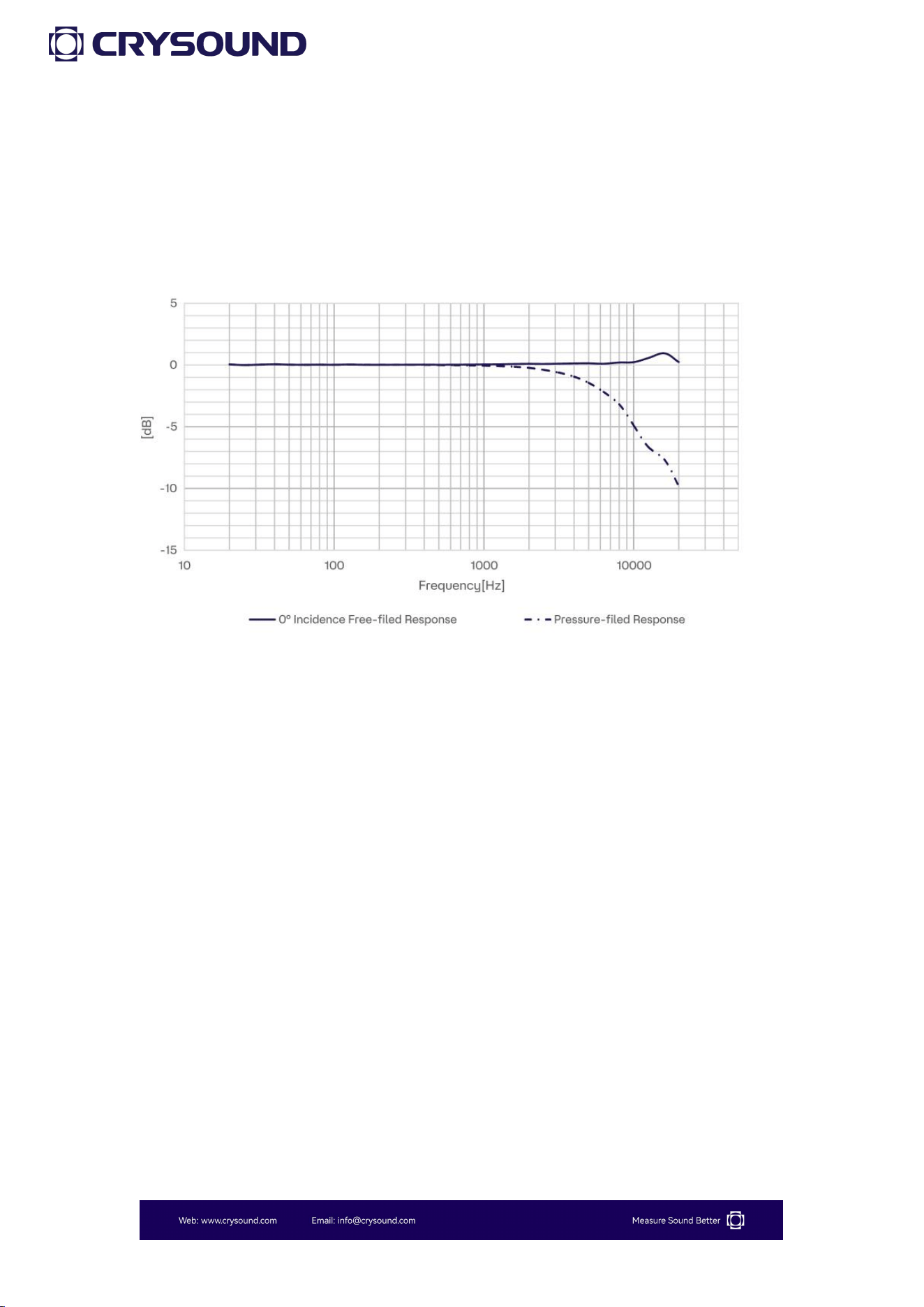
Appendix B: CRY333 Typical Frequency
Response (0° Incidence Angle)
37
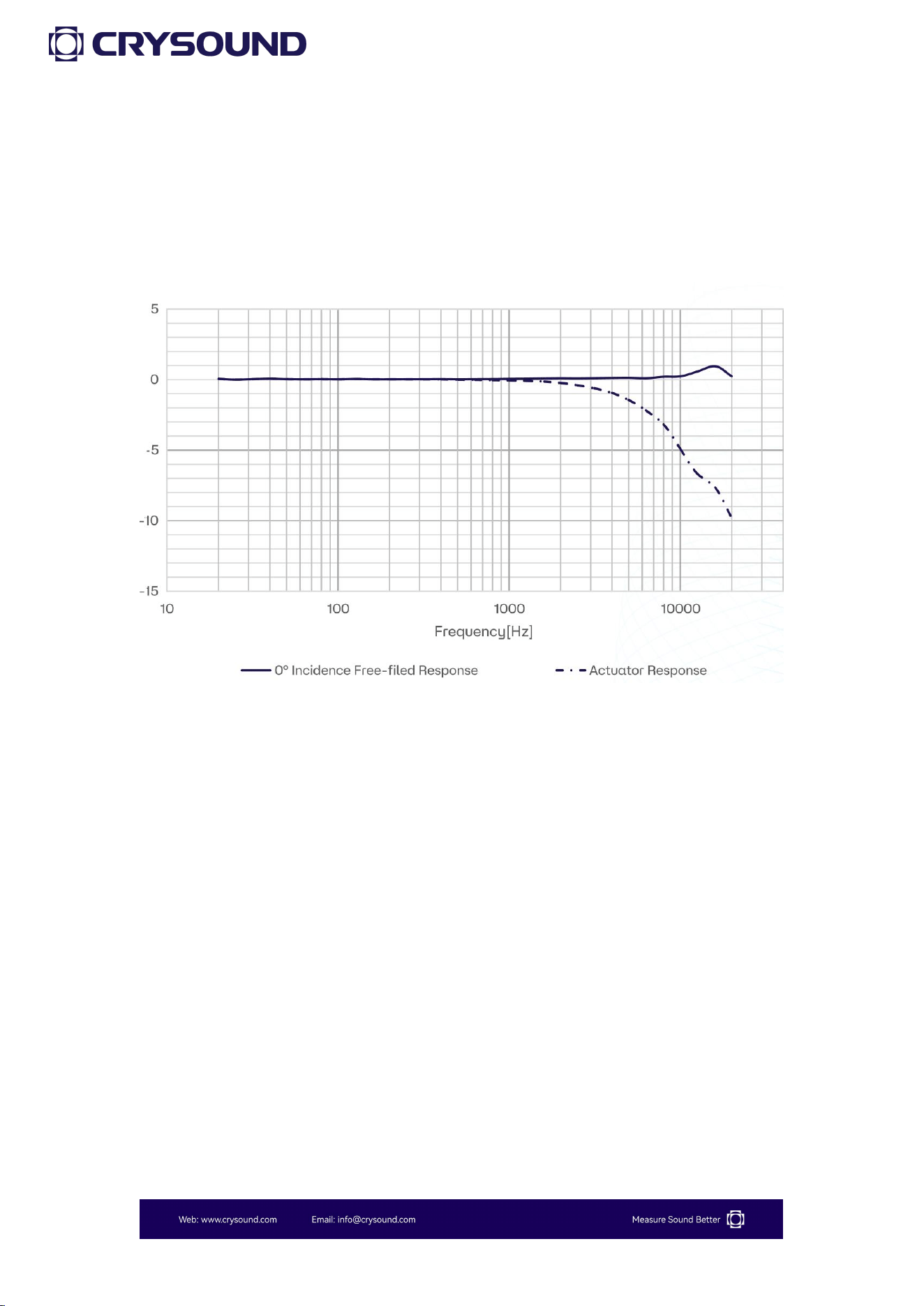
Appendix C: CRY331 Typical Frequency
Response (0° Incidence Angle)

38
Appendix D: Impact of Extension Cable
Note: The CRY2833 & CRY2834 sound level meters are equipped with a 5-meter
extension cable.
SPL
140dB
130dB
120dB
110dB
125Hz
0
0
0
0
250Hz
0
0
0
0
315Hz
0
0
0
0
400Hz
0
0
0
0
500Hz
0
0
0
0
630Hz
0
0
0
0
800Hz
0
0
0
0
1kHz
0
0
0
0
1.25kHz
0
0
0
0
1.6kHz
0
0
0
0
2.0kHz
0
0
0
0
2.5kHz
0
0
0
0
3.15kHz
0
0
0
0
4kHz
0
0
0
0
5kHz
0
0
0
0
6.3kHz
0
0
0
0
8kHz
0.1
0
0
0
10kHz
0.5
0
0
0
12.5kHz
1.0
0
0
0
16kHz
2.0
0
0
0

39
Appendix E: The Usage Instructions for the
Bluetooth® Printer
Power On: Press and hold the power button for 3 seconds to turn on the
printer. The working status indicator will light up; if the power button is not
pressed for 3 seconds, the printer will not turn on.
Power Off: While in the powered-on state, press and hold the power
button for 3 seconds to turn off the printer; the working status indicator will
go out.
Paper Feed: Press and hold the paper feed button to automatically feed the
paper.
Printer Usage Precautions:
a. Ensure all cables are properly connected before powering on the printer.
b. Always use the original charger and connection cables to avoid
malfunctions.
c. Regularly charge batteries that are not frequently used to extend their
lifespan.
d. Use compliant paper rolls to prolong the life of the printer's heating
element.
e. Do not print without paper, as this can severely damage the thermal print
head.