MICROWAVE OVEN
USER MANUAL
Warning notices: Before using this product, please read this manual carefully and keep it for future reference.
The design and specifications are subject to change without prior notice for product improvement. Consult
with your dealer or manufacturer for details.
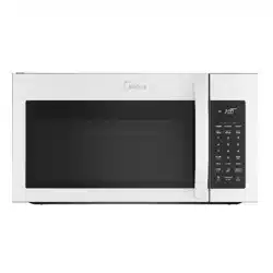
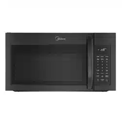
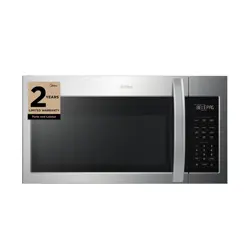
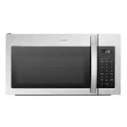
The diagram above is just for reference. Please take the appearance of the actual product as the standard.
MMO17S5AST
MMO17S5AWW
MMO17S5ABB

THANK YOU LETTER
Thank you for choosing Midea! Before using your new Midea product, please read
this manual thoroughly to ensure that you know how to operate the features and
CONTENTS
functions that your new appliance offers in a safe way.
THANK YOU LETTER
THANK YOU LETTER
--------------------------------------------------
SAFETY INSTRUCTIONS
----------------------------------------------
SPECIFICATION
---------------------------------------------------------
PRODUCT OVERVIEW
-------------------------------------------------
PRODUCT INSTALLATION
-------------------------------------------
OPERATION INSTRUCTIONS
----------------------------------------
TROUBLESHOOTING
--------------------------------------------------
TRADEMARKS, COPYRIGHTS AND LEGAL STATEMENT
---
DATA PROTECTION NOTICE
-------------------------------------- --
EN-01
EN-01
EN-02
EN-11
EN-12
EN-
EN-51
EN-61
EN-62
EN-63
13
Danger
This symbol indicates that there are dangers to the life and health of
persons due to extremely flammable gas.
Warning of electrical voltage
This symbol indicates that there is a danger to life and health of
persons due to voltage.
Warning
The signal word indicates a hazard with a medium level of risk which, if
not avoided, may result in death or serious injury.
Caution
The signal word indicates a hazard with a low degree of risk which, if
not avoided, may result in minor or moderate injury.
Attention
The signal word indicates important information (e.g. damage to
property), but not danger.
Observe instructions
This symbol indicates that a service technician should only operate and
maintain this appliance in accordance with the operating instructions.
Intended Use
SAFETY INSTRUCTIONS
Read these operating instructions carefully and attentively before using/commissioning the
unit and keep them in the immediate vicinity of the installation site or unit for later use!
The following safety guidelines are intended to prevent unforeseen risks or damage from
unsafe or incorrect operation of the appliance. Please check the packaging and appliance
on arrival to make sure everything is intact to ensure safe operation. If you find any
damage, please contact the retailer or dealer. Please note modifications or alterations to
the appliance are not allowed for your safety concern. Unintended use may cause
hazards and loss of warranty claims.
Explanation of Symbols
SAFETY INSTRUCTIONS
EN-02

PRECAUTIONS TO AVOID
POSSIBLE EXPOSURE TO
EXCESSIVE MICROWAVE
ENERGY
a. Do not attempt to operate this oven with the
door open since open door operation can result in
harmful exposure to microwave energy.
It is important not to defeat or tamper with the
safety interlocks.
b. Do not place any object between the oven front
face and the door or allows soil or cleaner residue
to accumulate on sealing surfaces.
c. Do not operate the oven if it is damaged. It is
particularly important that
the oven door close properly and that there is no
damage to the:
- DOOR (bent)
- HINGES AND LATCHES (broken or loosened)
- DOOR SEALS AND SEALING SURFACES
d. The oven should not be adjusted or repaired by
anyone except properly qualified service personnel.
EN-03

IMPORTANT SAFETY
INSTRUCTIONS
When using electrical appliances basic safety
precautions should be followed, including the
following:
WARNING
To reduce the risk of burns, electric shock, fire, injury
to persons or exposure to excessive microwave energy:
• Read all instructions before using the appliance.
• Read and follow the specific: " PRECAUTIONS
TO AVOID POSSIBLE EXPOSURE TO EXCESSIVE
MICROWAVE ENERGY " found on page 3.
• This appliance must be grounded. Connect only to
properly grounded outlet. See
" GROUNDING INSTRUCTIONS " found on page 7.
• Install or locate this appliance only in accordance
with the provided installation instructions.
• Some products such as whole eggs and sealed
containers - for example, closed glass jars - are able
to explode and should not be heated in this oven.
• Use this appliance only for its intended use as
described in the manual. Do not use corrosive
chemicals or vapors in this appliance. This type of
oven is specifically designed to heat, cook or dry
food. It is not designed for industrial or laboratory
use.
•
• Do not operate this appliance if it has a damaged
cord or plug, if it is not working properly, or if it has
been damaged or dropped.
EN-04
HOT CONTENTS CAN CAUSE SEVERE BURNS.
DO NOT ALLOW CHILDREN TO USE THE
MICROWAVE. Use caution when removing hot items.

• This appliance should be serviced only by qualified
service personnel. Contact nearest authorized service
facility for examination, repair, or adjustment.
• Do not cover or block any openings on the appliance.
• Do not store this appliance outdoors. Do not use this
product near water - for example, near a kitchen sink,
in a wet basement, near a swimming pool, or similar
location.
• Do not immerse cord or plug in water.
• Keep cord away from heated surface.
• Do not let cord hang over edge of table or counter.
• When cleaning surfaces of door and oven that
comes together on closing the door, use only mild,
nonabrasive soaps, or detergent applied with a
sponge or soft cloth.
• To reduce the risk of fire in the oven cavity:
- Do not overcook food. Carefully attend appliance
when paper, plastic, or other combustible materials
are placed inside the oven to facilitate cooking.
- Remove wire twist-ties from paper or plastic bag
before placing bag in oven.
- If material inside of the oven ignite, keep oven
breaker panel.
- Do not use the cavity for storage purposes. Do not
leave paper products, cooking utensils, or food in
the cavity when not in use.
• Liquids, such as water, coffee, or tea are able to
be overheated beyond the boiling point without
appearing to be boiling. Visible bubbling or boiling
when the container is removed fr
om the microwave
oven is not always present.
door closed, turn oven off, and disconnect the
power cord, or shut off power at the fuse or circuit
EN-05

THIS COULD RESULT IN VERY HOT LIQUID
SUDDENLY BOILING OVER WHEN THE CONTAINER
IS DISTURBED OR A UTENSIL IS INSERTED INTO
THE LIQUID. To reduce the risk of injury to persons:
- Do not overheat the liquid.
- Stir the liquid both before and halfway through
heating it.
- Do not use straight-sided containers with narrow
necks.
- After heating, allow the container to stand in the
microwave oven for a short time before removing
the container.
- Use extreme care when inserting a spoon or other
utensil into the container.
• Oversized food or oversized metal utensils should
not be inserted in a microwave/toaster ov
en as they
may create a fire or risk of electric shock.
• Do not clean with metal scouring pads. Pieces can
burn off the pad and touch electrical parts involving
a risk of electric shock.
• Do not use paper products when appliance is
operated in the toaster mode.
• Do not store any materials, other than manufacturer's
recommended accessories, in this oven when not in
use.
• Do not cover racks or any other part of the oven with
metal foil. This will cause overheating of the oven.
• Clean Ventilation Hoods Frequently - Grease should
not be allowed to accumulate on hood or filter.
• When flaming foods under the hood, turn the fan on.
• Use care when cleaning the vent-hood filter.
Corrosive cleaning agents, such as lyebased oven
cleaners, may damage the filter.
EN-06
• Suitable for use above both gas and electric cooking
equipment.
SAVE THESE INSTRUCTIONS
GROUNDING INSTRUCTIONS
This appliance must be grounded. In the event of an
electrical short circuit, grounding reduces the risk of
electric shock by providing an escape wire for the
electric current. This appliance is equipped with a cord
having a grounding wire with a grounding plug. The
plug must be plugged into an outlet that is properly
installed and grounded.
WARNING
Improper use of the grounding can result in a risk
of electric shock. Consult a qualified electrician or
serviceman if the grounding instructions are not
completely understood, or if doubt exists as to
whether the appliance is properly grounded. If it is
necessary to use an extension cord, use only a 3-wire
extension cord that has a 3-blade grounded plug,
and 3-slot receptacle that will accept the plug on the
appliance. The marked rating of the extension cord
shall be equal to or greater than the electrical rating of
the appliance.
DANGER
Electric Shock Hazard
Touching some of the internal components can cause
serious personal injury or death. Do not disassemble
this appliance.
EN-07

WARNING
Electric Shock Hazard
Improper use of the grounding can result in electric
shock. Do not plug into an outlet until appliance is
properly installed and grounded.
• A short power-supply cord is provided to reduce
the risks resulting from becoming entangled in or
tripping over a longer cord.
• Longer cord sets or extension cords are available and
may be used if care is exercised in their use.
• If a long cord or extension cord is used:
- The marked electrical rating of the cord set or
extension cord should be at least as great as the
electrical rating of the appliance.
- The extension cord must be a grounding-type
3-wire cord.
- The longer cord should be arranged so that it will
not drape over the counter top or tabletop where
it can be pulled on by children or tripped over
unintentionally.
RADIO INTERFERENCE
• Operation of the microwave oven may cause
interference to your radio, TV or similar equipment.
• When there is interference, it may be reduced or
eliminated by taking the following measures:
- Clean door and sealing surface of the oven
- Reorient the receiving antenna of radio or
television.
- Relocate the microwave oven with respect to the
receiver.
- Move the microwave oven away from the receiver.
EN-08
- Plug the microwave oven into a different outlet so
that microwave oven and receiver are on different
branch circuits.
THIS DEVICE COMPLIES WITH
PART 18 OF THE FCC RULES.
UTENSILS
CAUTION
Personal Injury Hazard
Tightly-closed utensils could explode. Closed
containers should be opened and plastic pouches
should be pierced before cooking.
See the instructions on "Materials you can use in
microwave oven or to be avoided in microwave oven."
There may be certain non-metallic utensils that are not
safe to use for microwaving. If in doubt, you can test
the utensil in question following the procedure below.
Utensil Test:
• Fill a microwave-safe container with 1 cup of cold
water (250ml) along with the utensil in question.
• Cook on maximum power for 1 minute.
• Carefully feel the utensil. If the empty utensil is warm,
do not use it for microwave cooking.
• Do not exceed 1 minute cooking time.
EN-09
Materials you can use in microwave oven
Utensils Remarks
Browning dish
Follow manufacturer’s instructions. The bottom of browning
dish must be at least 3/16 inch (5mm) above the turntable.
Incorrect usage may cause the turntable to break.
Dinnerware
Microwave-safe only. Follow manufacturer's instructions. Do
not use cracked or chipped dishes.
Glass jars
Always remove lid. Use only to heat food until just warm.
Most glass jars are not heat resistant and may break.
Glassware
Heat-resistant oven glassware only. Make sure there is no
metallic trim. Do not use cracked or chipped dishes.
Oven cooking bags
Follow manufacturer’s instructions. Do not close with metal
tie. Make slits to allow steam to escape.
Paper plates and cups
Use for short–term cooking/warming only. Do not leave
oven unattended while cooking.
Paper towels
Use to cover food for reheating and absorbing fat. Use with
supervision for a short-term cooking only.
Parchment paper
Use as a cover to prevent splattering or a wrap for
steaming.
Plastic
Microwave-safe only. Follow the manufacturer’s instructions.
Should be labeled "Microwave Safe". Some plastic
containers soften, as the food inside gets hot. "Boiling
bags" and tightly closed plastic bags should be slit, pierced
or vented as directed by package.
Plastic wrap
Microwave-safe only. Use to cover food during cooking
to
retain moisture. Do not allow plastic wrap to touch food.
Thermometers Microwave-safe only (meat and candy thermometers).
Wax paper Use as a cover to prevent splattering and retain moisture.
Materials to be avoided in microwave oven
Utensils Remarks
Aluminum tray May cause arcing. Transfer food into microwave-safe dish.
Food carton with metal
handle
May cause arcing. Transfer food into microwave-safe dish.
Metal or metal-trimmed
utensils
Metal shields the food from microwave energy. Metal trim
may cause arcing.
Metal twist ties May cause arcing and could cause a fire in the oven.
Paper bags May cause a fire in the oven.
Plastic foam
Plastic foam may melt or contaminate the liquid inside
when exposed to high temperature.
Wood
Wood will dry out when used in the microwave oven and
may split or crack.
EN-10

EN-11
SPECIFICATION
MODEL
MMO17S5AST/MMO17S5AWW/
MMO17S5ABB
120VAC 60Hz
1550 W
1000 W
Rated Input(Microwave)
Rated Output(Microwave)
Rated Voltage/Frequency
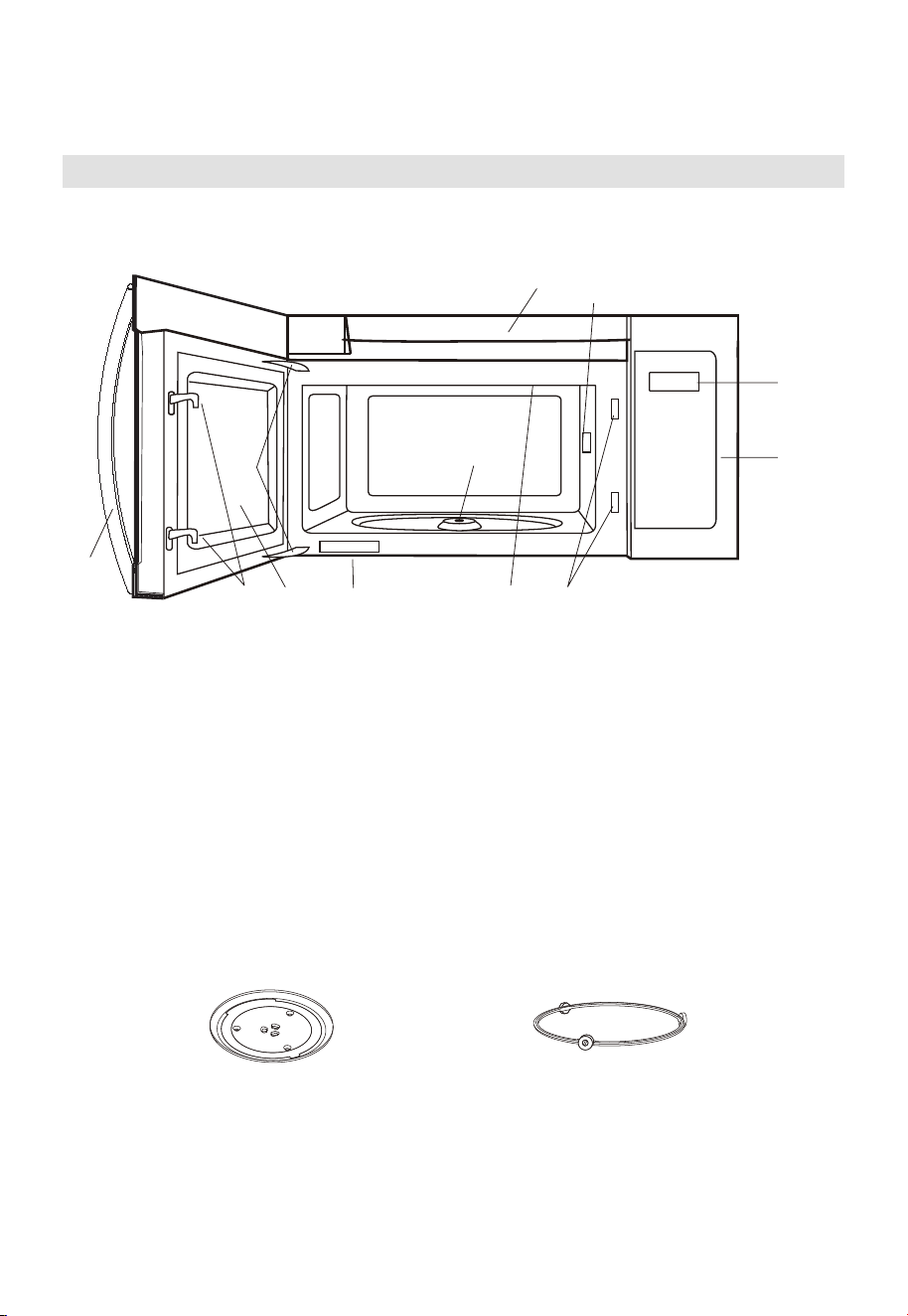
PRODUCT OVERVIEW
Setting Up Your Oven
PART NAMES
9
8
10
3
65
4
11
16
2
7
1. Microwave oven door with see-through window
2. Door hinges
3. Waveguide cover: DO NOT REMOVE.
4. Turntable motor shaft
5. Microwave oven light
It will light when microwave oven is operating or door is open.
6. Safety door latches
The microwave oven will not operate unless the door is securely closed.
7. Handle
8. Control panel
9.
10. Ventilation openings
11. Rating label
Glass turntable Turntable Ring Assembly
Display
EN-12
PRODUCT INSTALLATION
Important Safety Instructions
This product requires a three-prong grounded outlet. The installer must perform a
ground continuity check on the power outlet box before beginning the installation to
ensure that the outlet box is properly grounded. If not properly grounded, or if the outlet
box does not meet electrical requirements noted (under ELECTRICAL REQUIREMENTS),
a qualified electrician should be employed to correct any deficiencies.
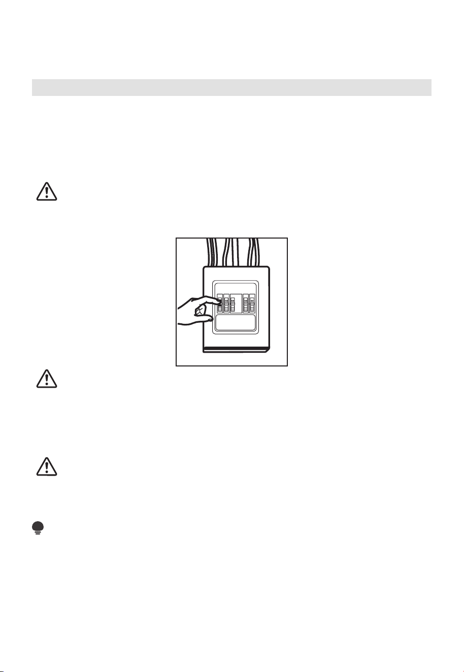
CAUTION:
For personal safety, remove house fuse or open circuit breaker before beginning
installation to avoid severe or fatal shock injury.
CAUTION:
For personal safety, the mounting surface must be capable of supporting the cabinet
load, in addition to the added weight of this 63–85 pound (28.5–38.5 kg) product, plus
additional oven loads of up to 50 pounds (22.7 kg) or a total weight of 113–135 pounds
(51.3–61.2 kg).
CAUTION:
For personal safety, this product cannot be installed in cabinet arrangements such as an
island or a peninsula. It must be mounted to BOTH a top cabinet AND a wall.
NOTE:
For easier installation and personal safety, it is recommended that two people install this
product.
IMPORTANT – PLEASE READ CAREFULLY. FOR PERSONAL SAFETY, THIS APPLIANCE
MUST BE PROPERLY GROUNDED TO AVOID SEVERE OR FATAL SHOCK.
EN-13
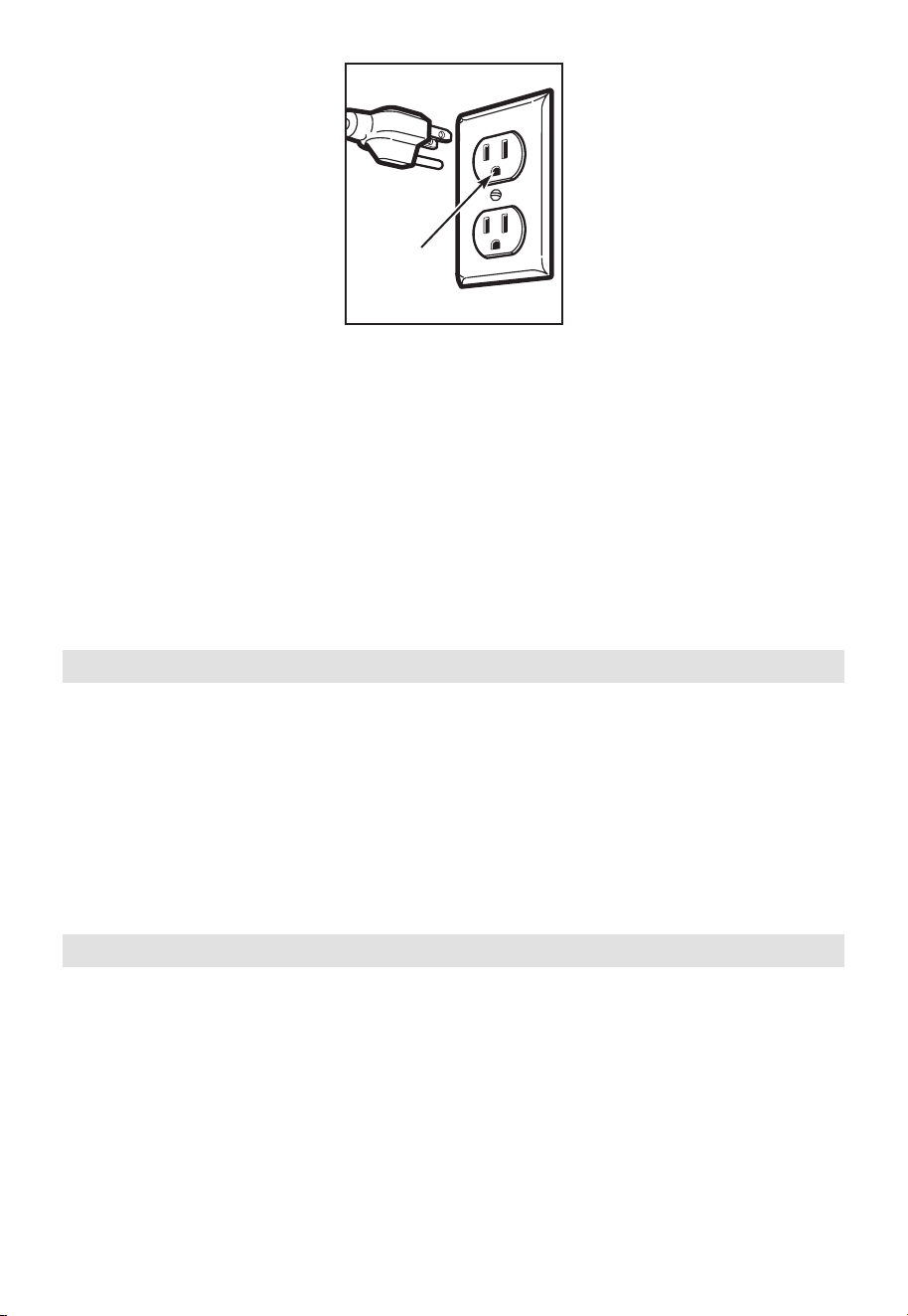
Ensure proper
ground exists
before use
The power cord of this appliance is equipped with a three-prong (grounding) plug
which mates with a standard three-prong (grounding) wall receptacle to minimize the
possibility of electric shock hazard from this appliance.
You should have the wall receptacle and circuit checked by a qualified electrician to
make sure the receptacle is properly grounded.
Where a standard two-prong wall receptacle is encountered, it is very important to have
it replaced with a properly grounded three-prong wall receptacle, installed by a qualified
electrician.
DO NOT, UNDER ANY CIRCUMSTANCES, CUT, DEFORM OR REMOVE ANY OF THE
PRONGS FROM THE POWER CORD. DO NOT USE WITH AN EXTENSION CORD.
Electrical Requirements
Product rating is 120 volts AC, 60 Hertz, 15 amps and 1.55 kilowatts. This product must
be connected to a seperate and dedicated supply circuit of the proper voltage and
frequency. Wire size must conform to the requirements of the National Electrical Code or
the prevailing local code for this kilowatt rating. The power supply cord and plug should
be brought to a seperate and dedicated 20 ampere branch circuit single grounded outlet.
The outlet box should be located in the cabinet above the microwave oven. The outler
box and supply circuit should be installed by a qualifed electrician and conform to the
National Electrical Code or the prevailing local code.
Damage—Shipment/Installation
1. If the unit is damaged in shipment, return the unit to the store in which it was bought
for repair or replacement.
2. If the unit is damaged by the customer, repair or replacement is the responsibility of
the custome
r.
3. If the unit is damaged by the installer (if other than the customer), repair or
replacement must be made by arrangement between customer and installer.
EN-14
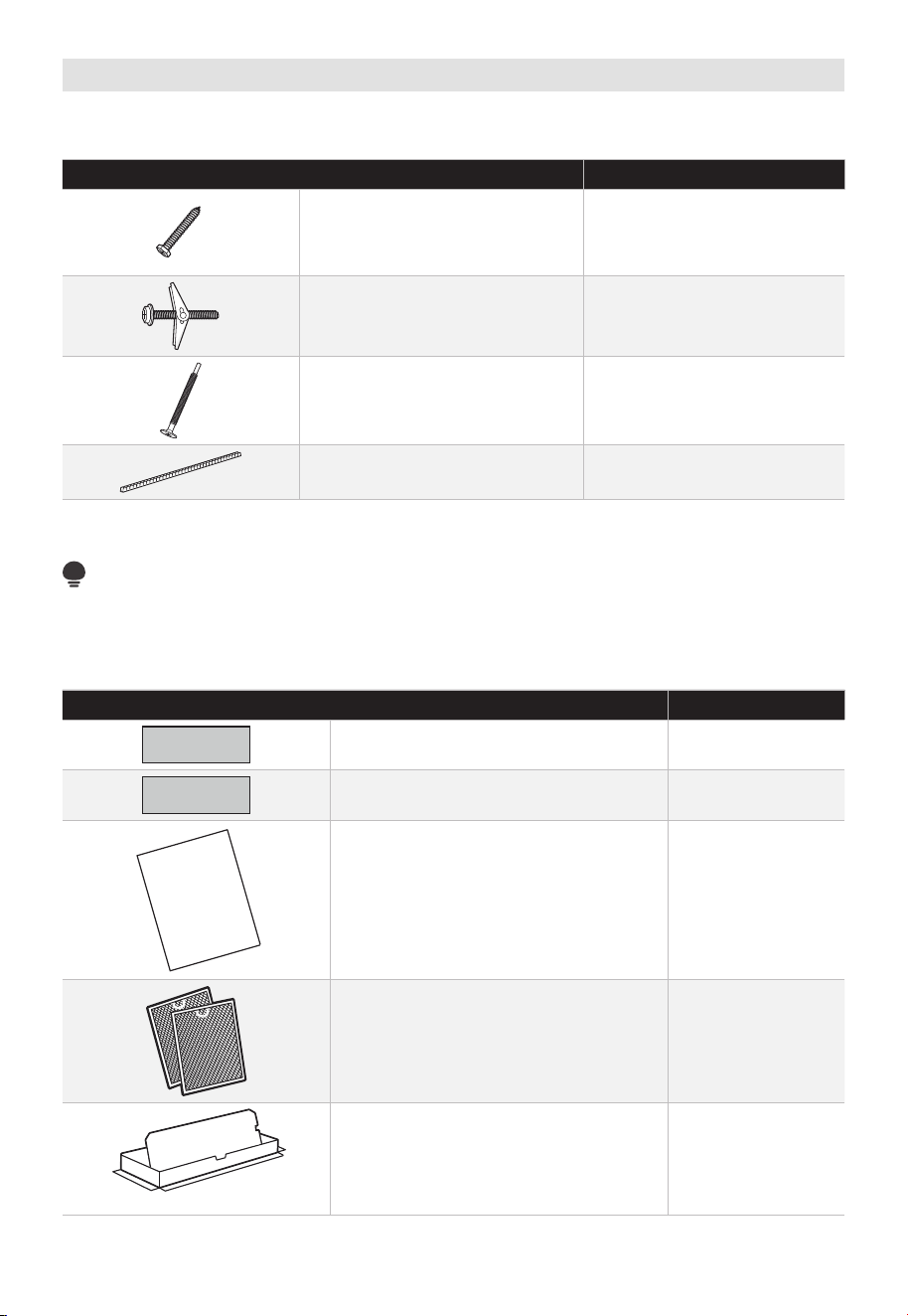
Parts Included
HARDWARE PACKET
PART QUANTITY
Wood Screws (
1
⁄
4
" x 2") 2
Toggle Bolts (and wing nuts)
(
3
⁄
16
" x 3")
2
Self-Aligning Machine Screws
(
1
⁄
4
"-28 x 3
1
⁄
4
")
3
Nylon Grommet
(for metal cabinets)
1
You will find the installation hardware contained in a packet with the unit. Check to make
sure you have all these parts.
NOTE:
Some extra parts are included.
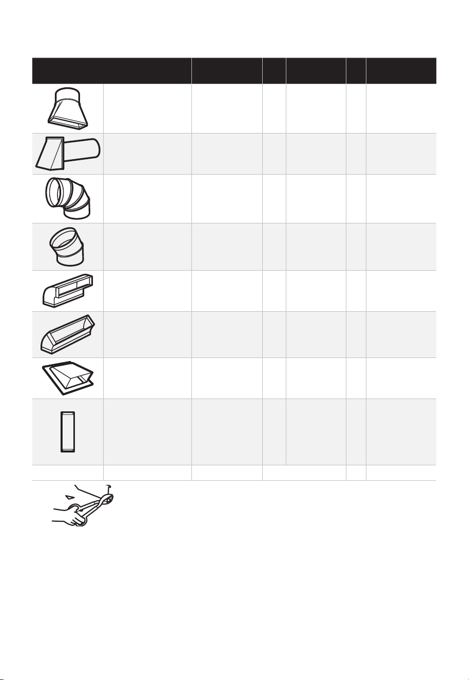
ADDITIONAL PARTS
PART QUANTITY
Top Cabinet Template 1
Rear Wall Template 1
Separately Packed Grease Filters 2
Exhaust adaptor 1
USER
MANUAL
1
User Manual
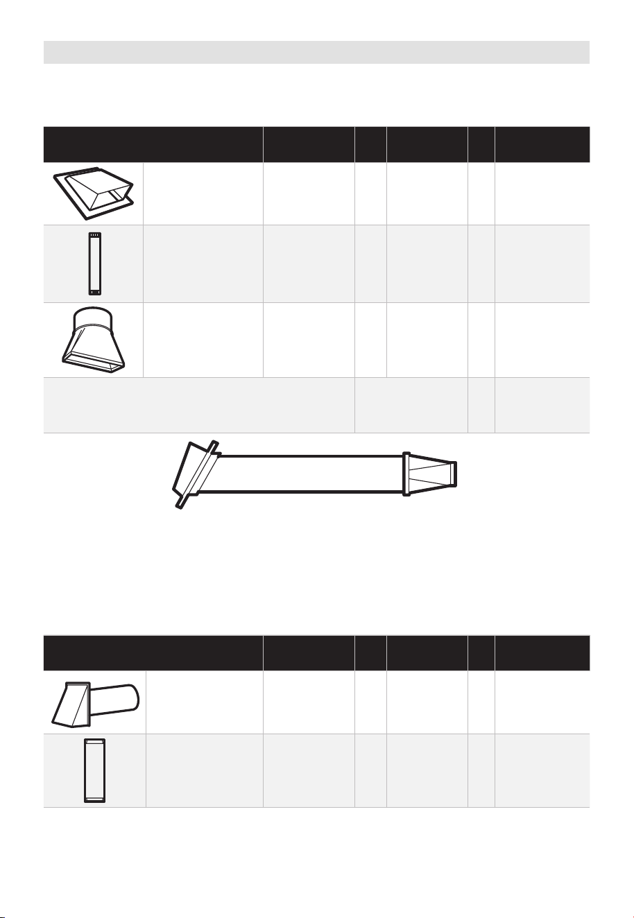
EN-15
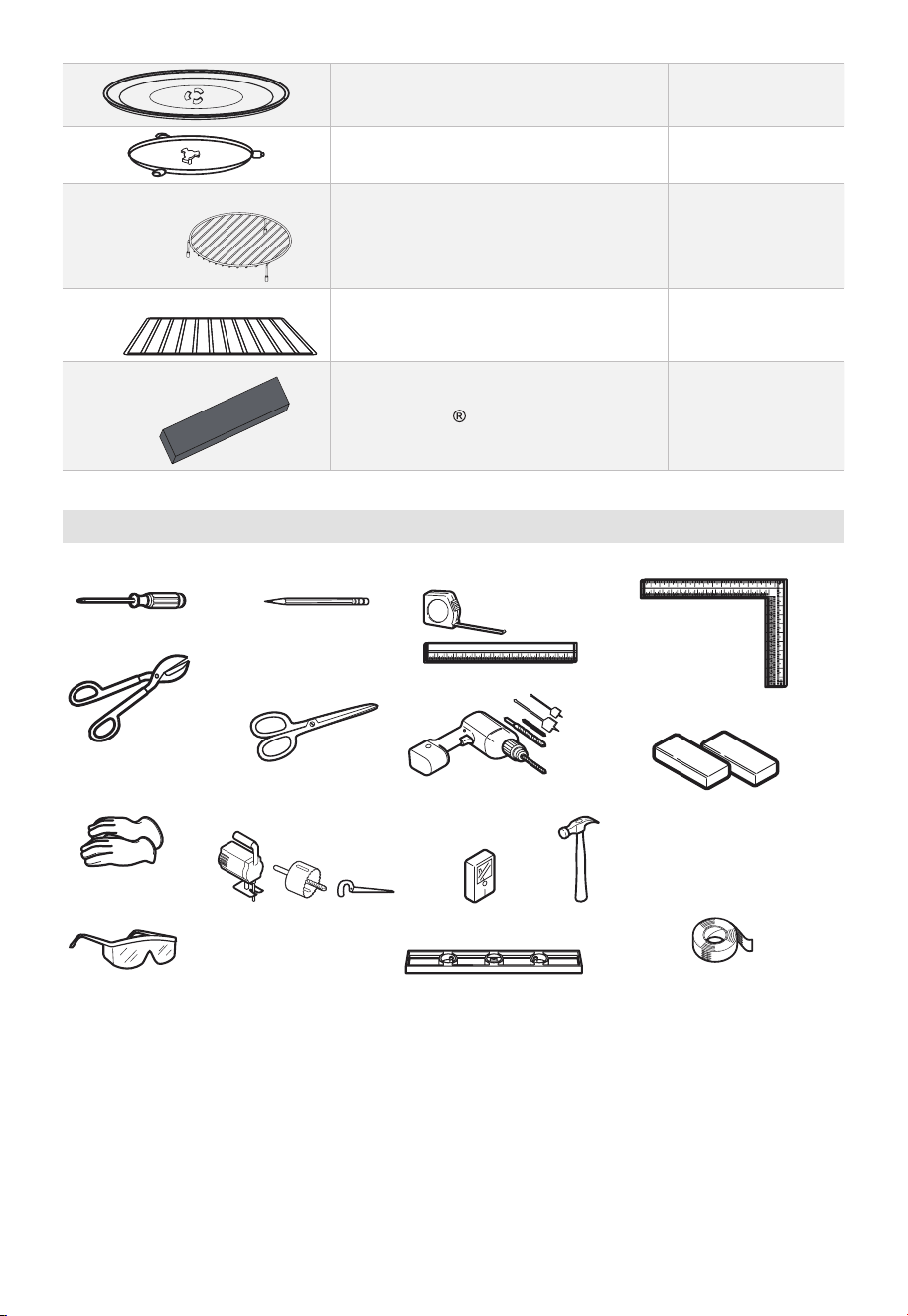
Glass Tray 1
Turntable Ring 1
For some models
Convection wire rack 1
For some models
Shelf 1
For some models
PureAir Microwave Filter 1
Tools You Will Need
# 1 Phillips screwdriver
Pencil
Ruler or tape measure
and straight edge
Carpenter square
(optional)
Tin snips (for cutting
damper, if required)
Hammer (optional)
Stud finder or
Gloves
Level
Saw (saber, hole or keyhole)
Filler blocks or scrap
wood pieces, if needed
for top cabinet spacing
(used on recessed bottom
cabinet installations only)
Duct and masking tape
Electric drill with
3
⁄16“,
1
⁄
2
“ and
5
⁄
8
“
drill bits
Scissors
(to cut template,
if necessary)
Safety goggles
EN-16
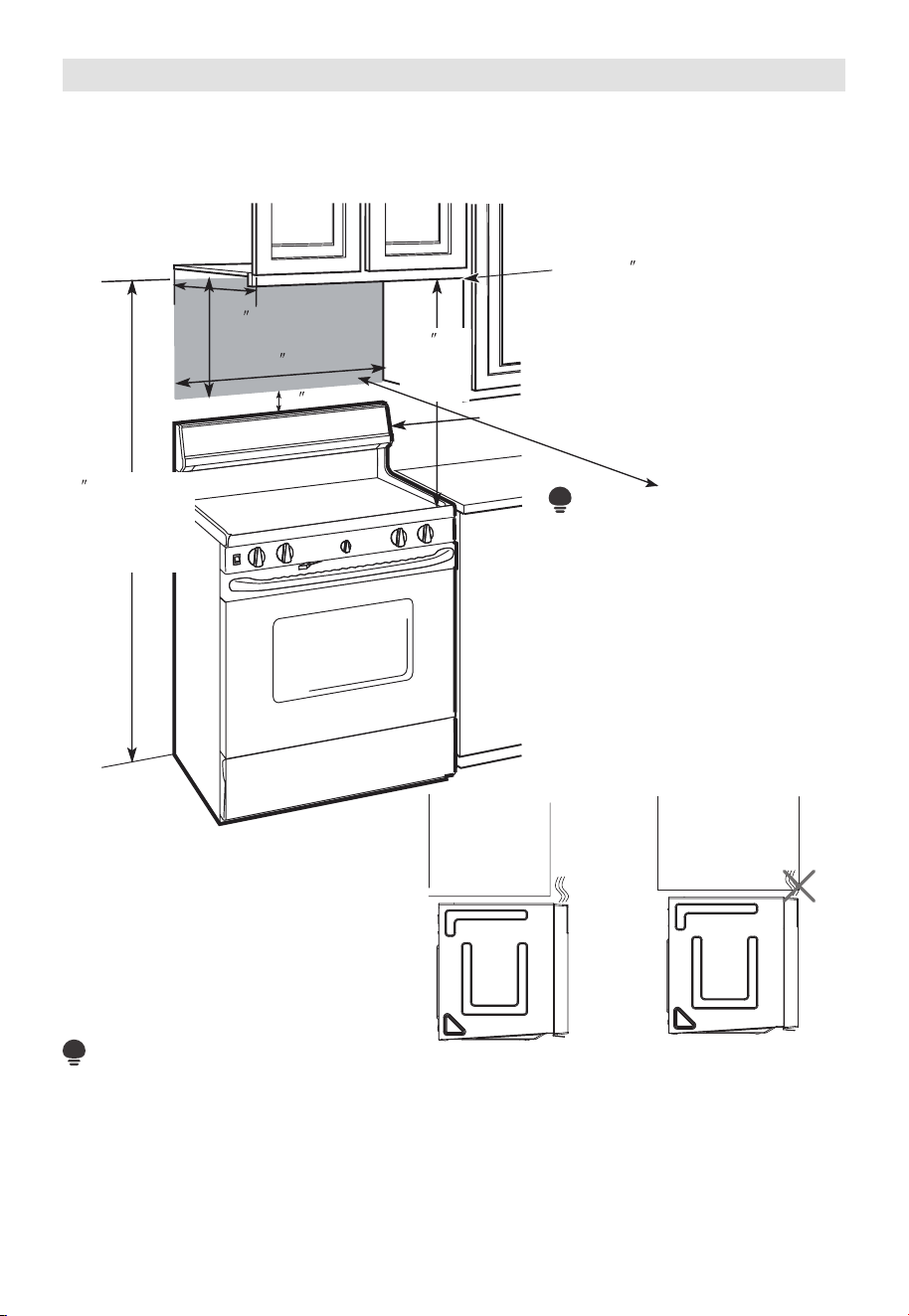
Mounting Space
MOUNTING SPACE
Bottom
Edge of
Cabinet
Needs
to
be 3 0 (76.2 cm)
or More from the
Cooking Surface
Backsplash
66 (167.6 cm)
or More from
the Floor to the
Top of the
Microwave
30 (76.2 cm)
2
(5.1cm)
30
min.
(76.2 cm)
16
1
⁄2
(41.9 cm)
13 Maximum (33 cm)
NOTE:
• The space between the cabinets must be 30" (76.2 cm)wide and free of obstructions.
• If you are going to vent your microwave oven to the outside, see Hood Exhaust
Section for exhaust duct preparation.
• When installing the microwave oven beneath smooth, flat cabinets, be careful to
follow the instructions on the top cabinet template for power cord clearance.
• As a guide to installation, see page 25 for Mounting Template Information.
• If the cabinet depth including
the cabinet doors is more than
13" then the unit must be
spaced out from wall using
adequate materials supporting
150 Ibs to allow proper top
vent air exhaust/intake.
“
NOTE:
EN-17
1. Placement Of The Mounting Plate
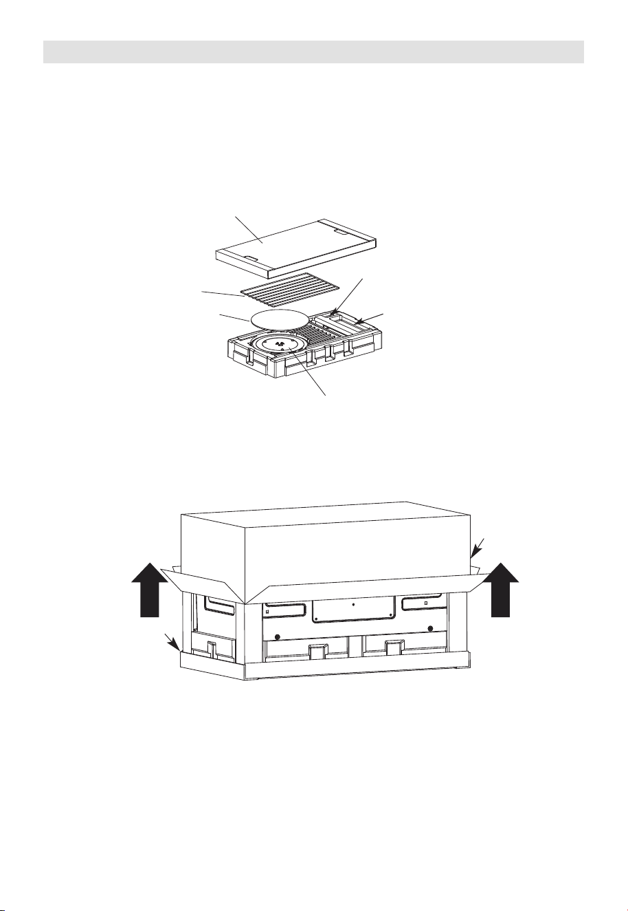
A. REMOVING THE MICROWAVE OVEN FROM THE CARTON/REMOVING THE
MOUNTING PLATE
1. Remove the top cover board, installation instructions, use and care, exhaust adapter,
turntable ring, shelf, filters, glass tray and the small hardwarebag. Do not remove the
Styrofoam protecting the front of the oven.
Filters and Turntable Ring below glass tray
Exhaust Adapter
Small Hardware Bag
Shelf (For
some models)
Top Cover Board
EPE Pad
2. Fold back all 4 carton flaps fully against carton sides. Then carefully roll the oven and
carton over onto the top side. The oven should be resting in the Styrofoam.
Carton
Styrofoam
3.
Pull the carton up and off the oven.
EN-18
Screws
Screws
Mounting Plate
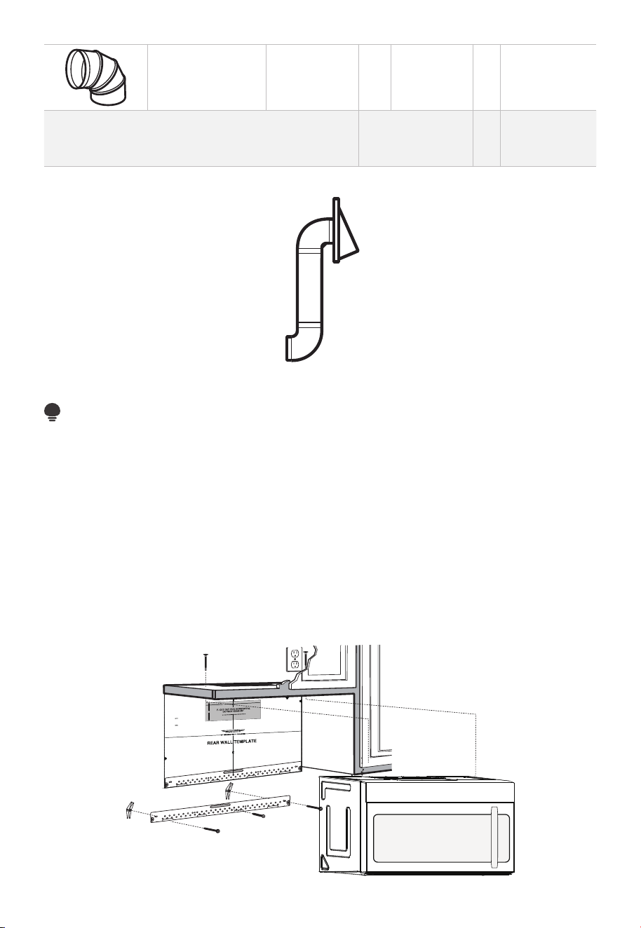
5. Remove the screws from each end of the mounting plate. This plate will be used as
the rear wall template and for mounting. Reinstall the screws into the holes where
they were removed.
B. FINDING THE WALL STUDS
Wall
Studs
Center
1. Find the studs, using one of the following methods:
- Stud finder – a magnetic device which locates nails.
- Use a hammer to tap lightly across the mounting surface to find a solid sound. This
will indicate a stud location.
2. After locating the stud(s), find the center by
probing the wall with a small nail to find the edges of the stud. Then place a mark
halfway between the edges. The center of any adjacent studs should be 16" (40.6 cm)
or 24" (61 cm) from this mark.
3. Draw a line down the center of the studs.
THE MICROWAVE MUST BE CONNECTED TO AT LEAST ONE WALL STUD.
4. Cut the middle of the outer protective plastic bag to remove the mounting plate
EN-19
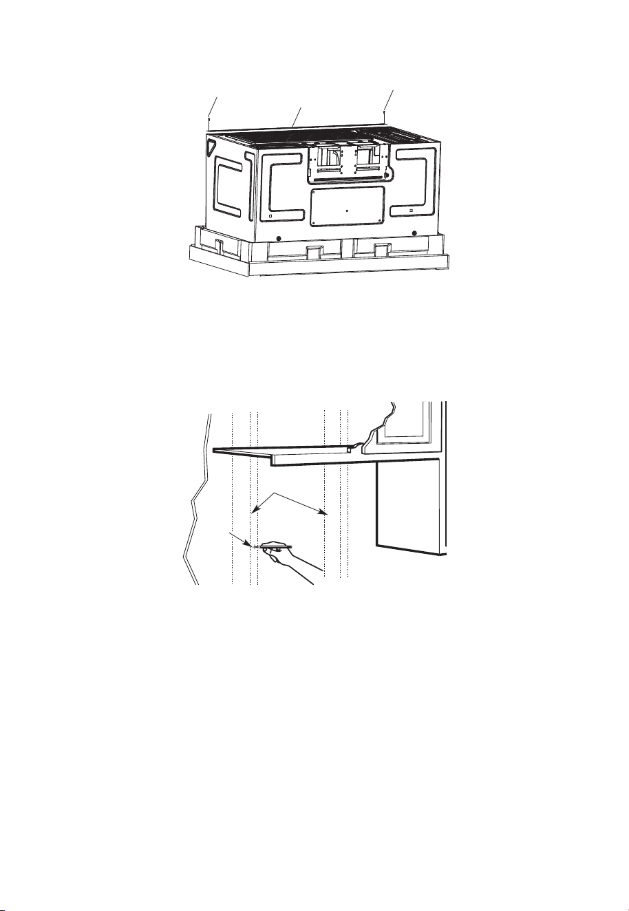
C. DETERMINING WALL PLATE LOCATION UNDER YOUR CABINET
Plate position-beneath flat bottom cabinet
At least 30
Draw a vertical line on the wall at the center of the 30" wide space.
Tape the Rear Wall Template onto the wall matching the centerline and touching the
bottom of the cabinet.
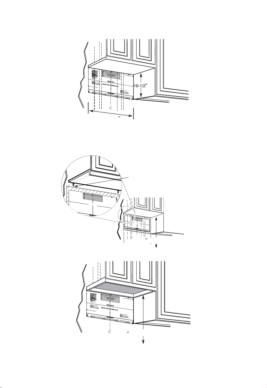
Plate position-beneath recessed bottom cabinet with front overhang
Draw a line on the
back wall equal to
the depth of the front
overhang.
Plate position-beneath framed recessed cabinet bottom
to Cooktop
30
Draw a vertical line on the wall at the center of the 30" space.
Tape the Rear Wall Template onto the wall matching the centerline and touching the
bottom cabinet frame.
C
3/
8"
TO
E
DGE
N
OT
E:
IT
I
S
VERY
IMP
O
R
T
A
NT
T
O
R
E
AD
A
ND
FO
LL
O
W
T
H
E
D
IR
E
C
T
I
ON
S
IN
T
H
E
IN
S
T
A
L
L
AT
I
ON
I
N
ST
R
UC
T
IO
N
S
B
E
F
OR
E P
R
O
CEE
DIN
G
WIT
H
T
HIS
RE
A
R
W
A
LL
T
E
MP
L
A
T
E.
Th
is
Re
a
r W
a
ll
Te
mpl
a
t
e
s
er
v
e
s
t
o p
o
s
it
io
n
t
h
e
bo
t
t
o
m
m
o
u
n
t
i
n
g
p
la
t
e
a
n
d
t
o
l
o
ca
t
e
t
h
e
h
o
ri
z
o
nt
a
l
e
x
h
au
st
o
u
t
le
t
.
1.
Us
e
a
le
v
e
l
t
o
c
h
ec
k
t
h
a
t
t
h
e
t
e
m
p
la
t
e
is
p
o
s
it
io
n
e
d
a
c
c
u
ra
t
e
ly
.
2
.
Lo
c
a
t
e
an
d
m
ar
k
at
le
a
s
t
o
n
e s
t
ud
o
n t
h
e
le
f
t
o
r
ri
ght
s
i
de
o
f
t
h
e
c
e
n
t
e
r
lin
e
.
I
t
is
im
po
rt
a
n
t
t
o
use at
l
e
a
st
o
ne
w
o
o
d
s
c
re
w
mo
u
n
te
d
f
ir
m
ly
in
a
s
t
u
d
to
s
u
p
p
o
r
t
the
w
e
ig
ht
o
f
t
h
e
m
ic
r
owa
v
e.
M
a
rk
t
w
o ad
d
it
i
o
na
l,
e
v
e
n
ly
s
pa
c
e
d
lo
c
at
io
n
s
for
th
e
s
u
pp
lie
d
t
o
gg
le
bo
lt
s
.
3
.
D
ril
l
h
o
le
s
in
t
he
m
a
rk
e
d
lo
c
a
t
io
n
s
.
Whe
re
th
e
re
is
a
s
t
ud,
d
r
ill
a
3
/
1
6
"
h
o
le
f
o
r
w
oo
d
s
c
re
w
s
.
F
or
h
o
le
s
th
at
d
o
n
ot
li
n
e
u
p
w
it
h
a
s
t
ud
,
d
rill
5
/
8
"
ho
le
s
fo
r
t
o
g
g
le
bo
lt
s.
D
O
N
O
T
I
NS
TALL
T
H
E
MO
U
N
T
I
N
G
P
L
A
T
E
AT
TH
IS
T
I
M
E
.
4
.
R
e
m
o
v
e
t
h
e
te
m
p
la
te
f
ro
m
t
h
e
r
e
ar
w
a
l
l.
5
.
R
e
v
i
e
w
t
h
e
I
n
s
t
a
lla
t
io
n
I
n
s
t
r
u
ct
ion
b
o
o
k
f
o
r
y
ou
r
i
n
sta
lla
t
io
n
s
i
t
u
at
io
n
.
L
o
c
a
te an
d
ma
rk
h
o
l
es
to
a
li
g
n w
it
h
h
o
l
e
s
i
n
the
mo
u
n
t
in
g
p
l
a
te.
I
MP
O
R
T
ANT
:
LO
C
AT
E
A
T
LEAS
T
ONE
S
T
U
D ON E
I
T
H
ER
S
I
DE
O
F
T
HE CE
NTE
R
LIN
E.
MA
RK
T
H
E
LOCAT
I
ON
FO
R
2
A
D
D
ITIO
NA
L, E
V
E
N
LY
S
P
AC
E
D TO
GG
LE B
OL
T
S IN
THE M
O
U
N
T
IN
G
P
L
AT
E
A
RE
A
.
Lo
ca
te a
n
d
ma
r
k ho
l
e
s to
a
lign with
h
oles in
t
h
e
mo
unt
i
ng p
l
a
t
e.
I
MP
O
RT
A
N
T:
LOCA
TE
AT
L
E
AST
ON
E
S
T
U
D
ON
EI
TH
E
R SID
E
O
F
T
H
E
C
ENT
E
RL
IN
E
.
MA
RK
TH
E LOC
A
TI
ON
F
OR
2 AD
D
I
T
I
ON
AL
,
E
V
E
N
L
Y
S
PAC
E
D
T
O
GG
L
E B
OL
T
S IN
T
H
E MO
U
N
T
IN
G
P
LAT
E
AR
E
A.
T
r
im
th
e
rea
r
w
a
l
l
te
m
p
l
ate
alo
ng t
h
e do
tte
d
lin
e
.
Trim
th
e r
ear
wa
l
l
te
m
p
l
a
te
a
lo
n
g
t
h
e
d
o
tte
d
line
.
1
2"
4
"
D
a
r
le
vu
e
lt
a
a
la
h
o
ja
p
a
ra
c
on
s
u
l
t
a
r
la
v
e
r
si
ó
n
e
n
E
sp
a
ño
l.
3/8
"
TO EDGE
N
O
TE
:
I
T
IS
VER
Y
IMPOR
T
AN
T T
O
R
EAD
AN
D
FO
L
LO
W
TH
E D
IR
EC
TI
O
N
S
I
N
T
H
E
I
N
ST
ALL
AT
IO
N
IN
ST
R
U
C
TI
O
N
S
B
EFO
R
E
PR
O
C
EED
IN
G
W
ITH
T
H
I
S
R
EAR
W
AL
L
T
EMPL
AT
E.
Th
is
R
e
a
r
W
a
ll
Te
mp
la
t
e s
er
v
e
s
to
p
o
s
it
i
o
n
th
e
b
o
t
to
m
mo
u
ntin
g
p
la
t
e
a
n
d
t
o l
o
c
at
e
th
e h
o
r
iz
on
ta
l e
x
h
a
us
t
ou
tle
t.
1
.
U
s
e
a
l
ev
e
l to
c
he
c
k
th
a
t
th
e
te
mp
la
t
e is
p
o
sitio
n
e
d
a
c
c
u
r
a
t
e
ly
.
2
.
L
o
c
a
te
a
n
d
ma
r
k
a
t le
a
s
t
o
n
e
s
t
u
d
o
n
t
he
le
ft
o
r
r
ig
ht
s
id
e
o
f
th
e c
e
n
te
r
l
in
e.
It
is
i
mp
o
r
ta
n
t t
o
u
s
e a
t le
a
s
t
o
n
e
w
o
o
d
s
c
r
e
w
mo
u
n
t
ed
f
ir
mly
in
a
s
tu
d
to
s
u
pp
o
r
t t
h
e
w
e
ig
h
t
o
f
th
e
mic
r
o
w
a
v
e
.
Ma
r
k
t
w
o
a
d
d
itio
na
l,
e
v
e
nl
y
s
p
a
ce
d
lo
c
a
tio
n
s
f
o
r
th
e
s
upp
li
e
d t
og
g
le
b
o
lts
.
3.
D
r
il
l h
ole
s
in
t
h
e
ma
r
k
e
d
lo
c
a
tio
n
s
.
W
h
e
r
e th
e
r
e
is
a
s
tu
d
, d
r
i
ll
a
3
/1
6"
h
o
le
fo
r
w
o
od
s
c
r
e
w
s
.
Fo
r
h
o
le
s
th
a
t d
o n
o
t lin
e
u
p
w
ith
a s
t
u
d
,
d
r
ill 5
/
8
" h
o
le
s fo
r
to
g
g
le
b
o
lts
.
D
O
N
O
T
IN
STA
L
L
TH
E
MO
U
N
TIN
G
P
L
ATE
AT TH
IS TIME
.
4
.
R
e
m
o
v
e
th
e
te
mp
la
te
fr
om
t
h
e
r
e
a
r
w
a
ll.
5
.
R
e
v
ie
w
t
he
In
s
ta
ll
atio
n
In
s
tru
c
t
io
n
bo
o
k fo
r
y
ou
r
in
sta
lla
tio
n
s
itu
a
tio
n.
Lo
cate an
d
ma
rk
h
ol
es t
o al
i
g
n w
it
h
h
ol
e
s
i
n t
h
e
mo
unti
n
g
pl
a
t
e
.
I
M
PO
R
T
AN
T
:
LOC
A
TE AT
LEAST
ONE ST
U
D
ON
EI
TH
ER
SI
D
E
OF
TH
E C
EN
TER
LIN
E.
MAR
K
T
H
E
LOC
ATIO
N
FO
R
2
AD
D
I
T
I
ON
AL
,
EVEN
L
Y
SPAC
ED
T
OG
GLE
BO
L
T
S
I
N
TH
E
MOUN
T
I
N
G
PLATE
AR
EA
.
Lo
cate
an
d
ma
rk
h
ol
es t
o al
i
g
n w
i
t
h
h
ol
e
s
in t
h
e
mo
un
tin
g pl
a
t
e
.
IMPO
R
T
AN
T:
LOC
AT
E AT
LEAS
T
ON
E ST
U
D
ON
EI
T
H
ER
SID
E
O
F
TH
E
C
EN
TE
R
LIN
E
.
MAR
K
T
H
E
LO
C
ATIO
N
F
O
R
2
AD
D
I
TI
ON
AL
, EVEN
L
Y
SPA
C
E
D
T
O
G
GLE
BO
L
T
S
I
N
TH
E
MO
U
N
TI
N
G
P
LAT
AR
EA.
Trim
th
e
r
e
ar
wall
t
em
p
lat
e
a
l
ong
th
e
d
otted
l
i
ne.
Trim
th
e
r
ear
wal
l
tem
pl
ate
a
l
ong
th
e
dotted
li
ne.
12
"
4"
D
arle
v
u
el
t
a
a
la
h
o
ja
p
a
r
a
c
o
n
s
u
lt
a
r
la
v
e
r
si
ó
n
e
n
E
s
p
añ
o
l.
to Cooktop
30
EN-20
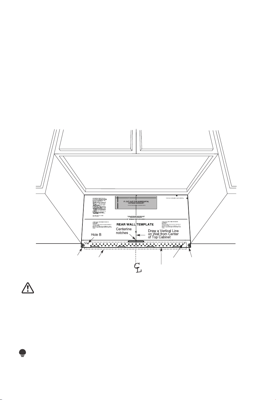
Your cabinets may have decorative trim that interferes with the microwave installation.
Remove the decorative trim to install the microwave properly and to make it level.
THE MICROWAVE MUST BE LEVEL.
Use a level to make sure the cabinet bottom is level.
If the cabinets have a front overhang only, with no back or side frame, install the
mounting plate down the same distance as the front overhang depth. This will keep the
microwave level.
1. Measure the inside depth of the front overhang.
2. Draw a horizontal line on the back wall an equal distance below the cabinet bottom as
the inside depth of the front overhang.
3. For this type of installation with front overhang only, align the mounting tabs with this
horizontal line, not touching the cabinet bottom as described in Step D.
D. ALIGNING THE WALL PLATE
Area E
Hole A
Horizontal Line
Draw a horizontal line on wall at the
bottom of “Rear Wall Template”.
Horizontal Line
3/8" TO EDGE
CAUTION:
Wear gloves to avoid cutting fingers on sharp edges.
1. Draw a vertical line on the wall at the center of the 30" wide space.
2. Draw a horizontal line on the wall at the bottom of "Rear Wall Template".
3. Find a wall stud in area "E" of mounting plate Refer to section 1B. Finding the wall
studs.
4. For attaching the mounting plate into stud drill a 3/16" hole into wood stud. Drill a
5/8" hole for toggle bolt in 1 other location (Hole A or Hole B)
NOTE:
DO NOT MOUNT THE PLATE AT THIS TIME.
EN-21
NOTE:
Holes A and B are inside area E. If neither of Holes A and B are not in a stud, find a stud
somewhere in area E and draw a circle to line up with the stud. It is important to have at
least one wood screw mounted firmly in a stud to support the weight of the microwave.
Set the mounting plate aside.
2. Installation Types (Choose A, B or C)
This microwave oven is designed for adaptation to the following three types of
ventilation:
A. Outside Top Exhaust (Vertical Duct)
B. Outside Back Exhaust (Horizontal Duct)
C. Recirculating (Non-Vented Ductless)
NOTE:
This microwave is shipped assembled for Recirculating. Select the type of ventilation
required for your installation and proceed to that section.
A. OUTSIDE TOP EXHAUST (VERTICAL DUCT)
Adaptor in Place for
Outside Top Exhaust
See page 26
B. OUTSIDE BACK EXHAUST (HORIZONTAL DUCT)
See page 33
Adaptor Must Be
Moved to the Back for
Outside Back Exhaust
EN-22

C. RECIRCULATING (NON-VENTED DUCTLESS)
See page 41
Models are shipped for recirculating exhaust. Some models have a disposable charcoal
filter installed to help remove smoke and odors.
NOTE:
Read the next two pages only if you plan to vent your exhaust to the outside. If you plan
to recirculate the air back into the room, proceed to page 23-26.
Installation Instructions For External Exhaust Ducting
NOTE:
If you need to install ducts, note that the total duct length of 3
1
⁄
4
" x 10" (8.2 x 25.4 cm)
rectangular or 5" (12.7 cm)diameter/ 6" ” (15.2 cm) diameter round duct should not
exceed 120 equivalent feet (36.5 m).
Outside ventilation requires an EXTERNAL EXHAUST DUCT.Read the following carefully.
NOTE:
It is important that venting be installed using the most direct route and with as few
elbows as possible. This ensures clear venting of exhaust and helps prevent blockages.
Also, make sure dampers swing freely and nothing is blocking the ducts.
Exhaust connection:
The exhaust adaptor has been designed to mate with a standard 3
1
⁄
4
" x 10” (8.2 x 25.4
cm) rectangular duct.
If a round duct is required, a rectangular-to-round transition adaptor must be used.
A5 " (12.7cm)/ 6" (15.2cm) diameter duct is acceptable to use.
Maximum duct length:
For satisfactory air movement, the total duct length of 3
1
⁄
4
" x 10" (8.2 x 25.4 cm)
rectangular or 5" (12.7 cm) diameter/ 6 "(15.2 cm) diameter round duct should not
exceed 120 equivalent feet (36.5 m).
Elbows, transitions, wall and roof caps, etc., present additional resistance to airflow and
are equivalent to a section of straight duct which is longer than their actual physical size.
When calculating the total duct length, add the equivalent lengths of all transitions and
adaptors plus the length of all straight duct sections. The chart below shows you how
EN-23
to calculate total equivalent ductwork length using the approximate feet of equivalent
length of some typical ducts.
DUCT PIECES
EQUIVALENT
LENGTH
x
NUMBER
USED
=
EQUIVALENT
LENGTH
Rectangular-to-
Round Transition
Adaptor*
5 Ft. (1.5 m) x ( ) = Ft. or m
Wall Cap 40 Ft. (12.2 m) x ( ) = Ft. or m
90° Elbow 10 Ft. (3 m) x ( ) = Ft. or m
45° Elbow 5 Ft. (1.5 m) x ( ) = Ft. or m
90° Elbow 25 Ft. (7.6 m) x ( ) = Ft. or m
45° Elbow 5 Ft. (1.5 m) x ( ) = Ft. or m
Roof Cap 24 Ft. (7.3 m) x ( ) = Ft. or m
Straight Duct 6"
(15.2 cm) Round or
3
1
⁄
4
" x 10"
(8.2 x 25.4 cm
Rectangular)
1 Ft. (0.3 m) x ( ) = Ft. or m
Total Ductwork = Ft. or m
* IMPORTANT: If a rectangular-to-round transition adaptor is used,
the bottom corners of the damper will have to be cut to fit, using
the tin snips, in order to allow free movement of the damper.
Equivalent lengths of duct pieces are based on actual tests and reflect requirements for
good venting performance with any vent hood.
EN-24
External Exhaust Ducting
OUTSIDE TOP EXHAUST (EXAMPLE ONLY)
The following chart describes an example of one possible ductwork installation.
DUCT PIECES
EQUIVALENT
LENGTH
x
NUMBER
USED
=
EQUIVALENT
LENGTH
Roof Cap 24 Ft. (7.3 m) x (1) = 24 Ft. (7.3 m)
12 Ft. (3.6 m)
Straight Duct
(6"/15.2 cm Round)
12 Ft. (3.6 m) x (1) = 12 Ft. (3.6 m)
Rectangular-to-
Round Transition
Adaptor*
5 Ft. (1.5 m) x (1) = 5 Ft. (1.5 m)
Equivalent lengths of duct pieces are based on
actual tests and reflect requirements for good
venting performance with any vent hood.
Total Length = 41 Ft. (12.5 m)
* IMPORTANT: If a rectangular-to-round transition adaptor is used, the bottom corners of
the damper will have to be cut to fit, using the tin snips, in order to allow free movement
of the damper.
OUTSIDE BACK EXHAUST (EXAMPLE ONLY)
The following chart describes an example of one possible ductwork installation.
DUCT PIECES
EQUIVALENT
LENGTH
x
NUMBER
USED
=
EQUIVALENT
LENGTH
Wall Cap 40 Ft. (12.2 m) x (1) = 40 Ft. (12.2 m)
3 Ft. Straight Duct
(3
1
⁄
4
"x 10"/8.2
x 25.4 cm
Rectangular)
3 Ft. (0.9 m) x (1) = 3 Ft. (0.9 m)
EN-25
90° Elbow 10 Ft. (3 m) x (2) = 20 Ft. (3 m)
Equivalent lengths of duct pieces are based on
actual tests and reflect requirements for good
venting performance with any vent hood.
Total Length = 63 Ft. (19.2 m)
NOTE:
For back exhaust, care should be taken to align exhaust with space between studs, or
wall should be prepared at the time it is constructed by leaving enough space between
the wall studs to accommodate exhaust.
A. OUTSIDE TOP EXHAUST (Vertical Duct)
INSTALLATION OVERVIEW
A1. Attach Mounting Plate to wall
A2. Prepare Top Cabinet
A3. Configure Microwave Blower for Outside / Top Exhaust
A4. Check Damper Operation
A5. Mount Microwave Oven
A6. Adjust Exhaust Adapter
A7. Connect Duct-work
12"
4"
NO
TE:
READ AND F
O
I
T
I
S
V
ER
Y
LLO
I
W
MPO
T
HE
R
D
TA
NT
T
O
IRECTIO
IN THE INSTALLAT
I
O
N
I
NSTRU
CTIO
N
N
S
S
BE
F
O
RE
PRO
H
T
H
T
IWGNIDEE
C
IS
REAR
W
ALL
TEM
PL
A
TE
.
ll Te
mpl
a
te
s
er
v
es
t
o
p
1
ou
a
. Us
mo
u
tl
e
t.
nti
n
e
a l
T
hi
s
R
ea
g
p
rW
l
a
a
t
e
a
nd
to
lo
ca
te
th
e
h
ori
z
o
s
o
n
itio
t
a
n
l e
t
h
xh
e b
au
o
st
t
t
o
m
ioned
to
chec
k
tha
t
th
e
t
e
mplate
is pos
it
pl
a
r
k hol
es
to a
l
i
gn
wi
th hol
es
i
n t
he
L
oca
t
mounting
RTANT
e and m
:
ate
.
IMPO
E
AT LEA
THE CENT
HE LO
CATIO
L
OC
AT
E
RL
INE
ST
.
O
NE STUD ON EI
FO
EDIS
R
EH
T
SP
AC
E
AREA.
MAR
K
T
D T
O
GGLE
BO
NF
LT
S
O
IN
R 2 ADD
IT
THE MO
IO
UN
NA
TING
L, EV
EN
L
PLA
TE
Y
Trim the r
e
ar wa
l
l tem
plat
e a
long
the
dot
t
ed
l
ine.
k h
ole
s
to
a
l
ig
n w
ith h
ole
s
in t
he
m
ounting
L
oca
t
e a
n
d
mar
O
RT
AN
T
plate.
:
IMP
AT LEA
THE
CENT
HE
L
OCATIO
SP
LOCATE
ER
L
I
N
E.
IE N
O
D
UT
SE
NO
T
S
TH
ER
SI
D
E OF
AR
E
A.
MARK
ACED
T
T
OG
G
LE B
O
N
FO
LTS IN
R 2
AD
DITI
ON
THE
MO
UN
A
T
ING
L,
EV
ENL
PLATE
Y
Trim the rear
w
a
l
l te
m
pl
at
e a
long
t
h
e
do
tt
ed
li
n
e.
3/8"
TO
EDGE
2. L
o
c
c
cu
a
te
r
a
e
a
te
ly
v
nd
el
.
m
a
r
k a
t leas
t
o
d
u
t
s
e
n
o
n
th r
o
t
f
e
l
e
igh
t
si
d
e of
t
h
e c
ent
e
rl
ine
.
r
It is im
p
o
rta
nt
to
u
s
e
at
l
e
ast
o
n
e
woo
d
sc
rew
mo
ro
unte
d
wa
v
fi
e.
r
M
ml
y
ar
i
k
n
t
a
w
s
o
a
t
ud
d
di
t
i
to
s
up
p
ona
l,
ev
or
en
t
the
w
ly
s
e
pa
ight
ced
e mic
f
e
o
r
s
i
n
t
he
t
h
s
e
u
m
ppl
ar
k
ied to
ed
l
o
g
c
g
le bo
l
ati
on
t
s
s
.
.
Wh
er
e t
her
e is
lo
o
f
a
c
th
3. Dr
a
th
s
i
tio
at
ll
tu
n
h
d
s
ol
d
ri
l
l
a
3/1
6"
h
ol
e fo
r
w
oo
d
sc
r
e
w
s
.
F
o
r
h
o
l
es
do
,
hti
w
p
u
e
a
stud,
d
ri
l
l
5
/8
" h
ol
es
fo
r
e b
o
n
o
lts
t
li
n
.
NO
T
t
oggl
IN
STAL
L
T
HE
MO
U
N
TI
NG
P
L
ATE
AT
4.
R
e
T
m
HI
S
T
D
O
th
IME.
e te
o
v
e
mp
l
a
te fr
omth
e r
ea
r
wall
.
5.Re
v
ie
w
the I
n
s
ta
ll
a
tsnIn
oi
t r
uc
t
i
on b
o
o
k
for y
ou
r
inst
al
l
a
t
io
n s
it
ua
tio
n
.
Dar
le
vu
el
t
a
ala
ho
japa
raco
ns
ul
t
ar
la
v
e
r
si
ón
en
Espa
ño
l.
EN-26
IMPORTANT NOTES:
1. Make sure the screws for the Blower Motor and Blower Plate are securely tight-ened
when they are installed. This will help to prevent excessive vibration.
2. Make sure the Motor wiring has been properly routed and secured, and that the wires
are not pinched.
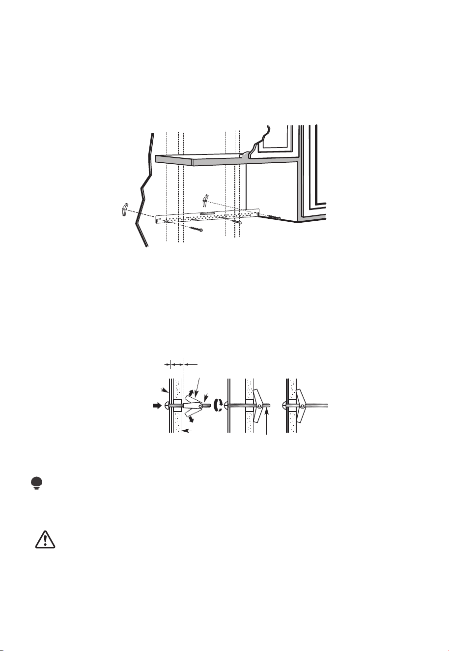
A1. ATTACH THE MOUNTING PLATE TO THE WALL
• Attach the plate to the wall using toggle bolts.
• At least one wood screw must be used to attach the plate to a wall stud.
1. Remove the toggle wings from the bolts
2. Insert the bolts into the mounting plate through the holes designated to go into
drywall and reattach the toggle wings to 3/4" (19mm) onto each bolt.
To use toggle bolts:
Wall
Mounting
Plate
Bolt End
Spacing for Toggles
More Than Wall
Thickness
Toggle
Bolt
Toggle Wings
3. Place the mounting plate against the wall and insert the toggle wings into the holes in
the wall to mount the plate.
NOTE:
Before tightening toggle bolts and wood screw, make sure the bottom of the mounting
plate touches the bottom of the cabinet when pushed flush against the wall and the plate
is properly centered under the cabinet.
CAUTION:
Be careful and avoid pinching fingers between the back of the mounting plate and the
wall.
4. Tighten all bolts. Pull the plate away from the wall to help tighten the bolts.
EN-27
A2. USE TOP CABINET TEMPLATE FOR PREPARATION OF TOP CABINET
You need to drill holes for the top support screws, a hole large enough for the power
cord to fit through, and a cutout large enough for the exhaust adaptor.
1. Read the instructions on the TOP CABINET TEMPLATE.
2. Tape it underneath the top cabinet.
3. Drill the holes, following the instructions on the TOP CABINET TEMPLATE.
CAUTION:
Wear safety goggles when drilling holes in the cabinet bottom.
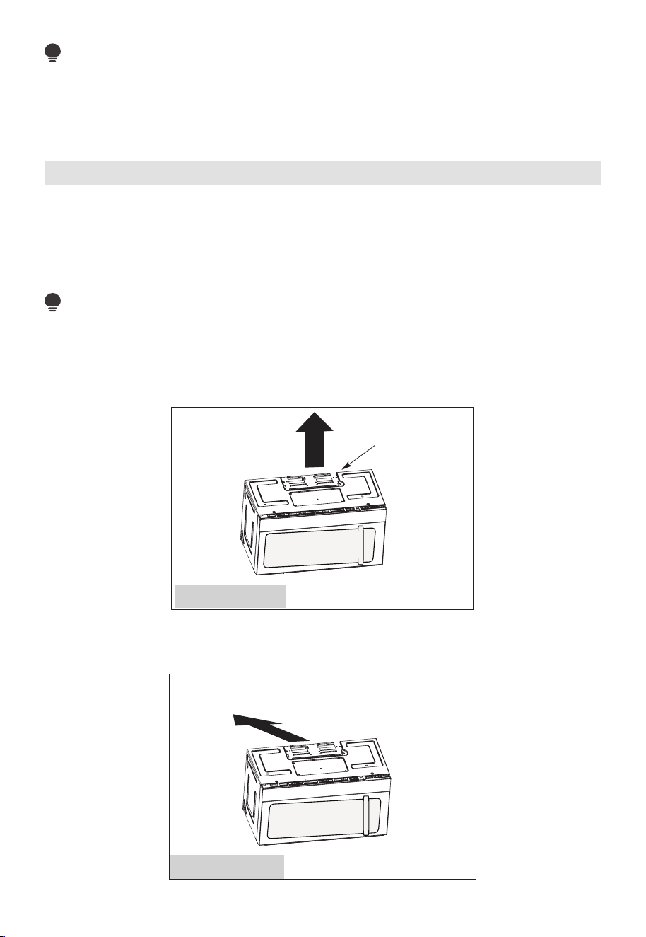
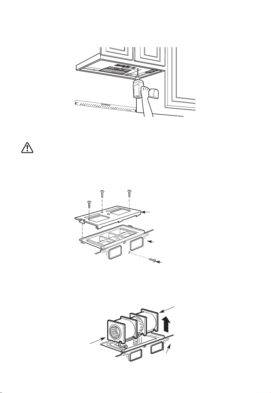
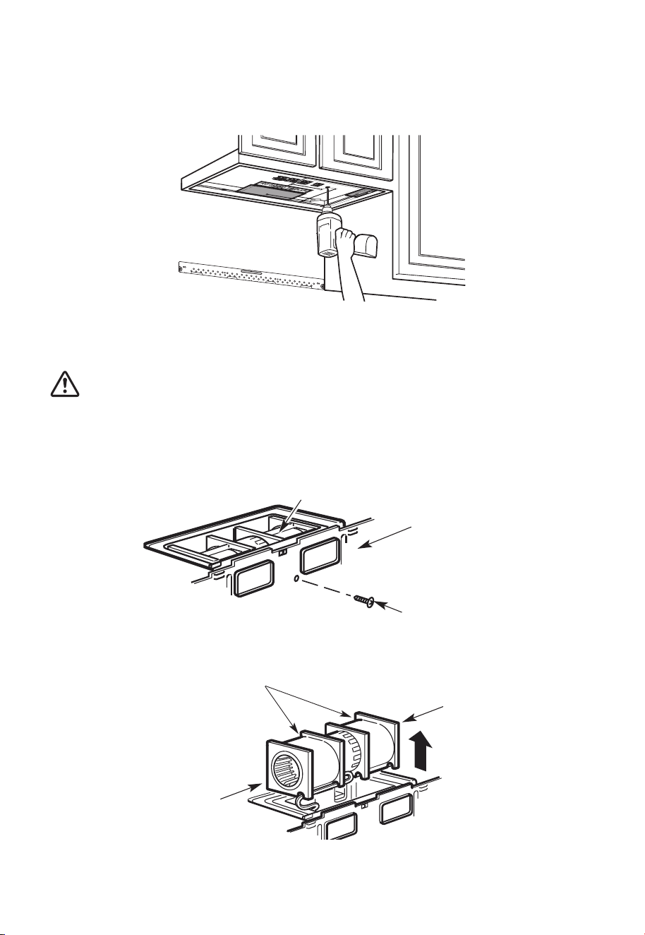
A3. ADAPTING MICROWA VE BLOWER FOR OUTSIDE TOP EXHAUST
1. Place the microwave in its upright position, with the top of the unit facing up.
Blower Plate
Blower Motor
Screw
Back of
Microwave
Remove the screw that holds the blower plate to the microwave. Remove and save the
screw holding the blower motor to the microwave.
2. Carefully pull out the blower unit. The wires will extend far enough to allow you to
adjust the blower unit.
Back of
Microwave
End B
End A
EN-28
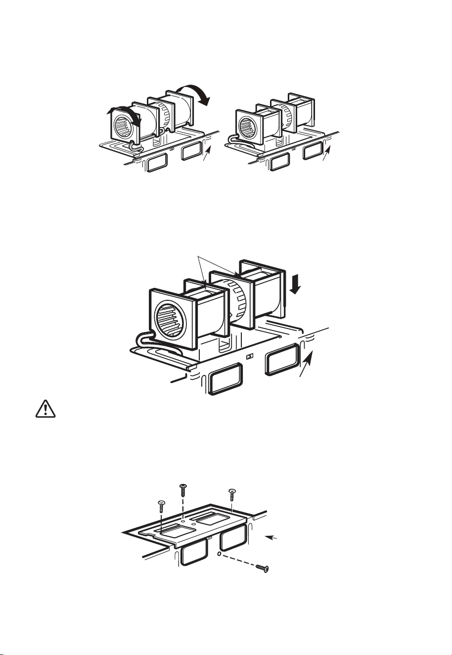
3. Roll the blower unit 90° so that fan blade openings are facing out the top of the
microwave.
Back of
Microwave
Back of
Microwave
Before Rotation After Rotation
4. Place the blower unit back into the opening.
Back of
Microwave
AFTER: Fan Blade
Openings Facing Top
CAUTION:
Do not pull or stretch the blower unit wiring. Make sure the wires are not pinched, and
that they are properly secured.
5. Secure blower unit to microwave with the screw removed in Step 1. Make sure the
screw is tight.
6. Replace blower plate with the screw removed in Step 1. Make sure the screw is tight.
Back of
Microwave
EN-29
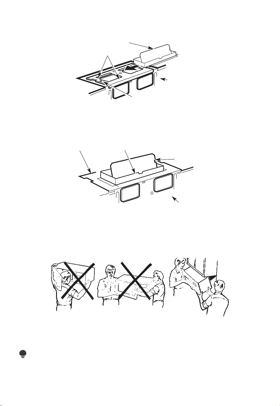
7. Attach the exhaust adaptor to the top of the blower plate by sliding it into the guides
of the blower plate.
Back of
Microwave
Guide
Adaptor
Locking Tab
Push in securely until it is in the locking tabs. Take care to assure that the damper hinge
is installed so that the damper swings freely.
A4. CHECK FOR PROPER DAMPER OPERATION
Back of
Microwave
Exhaust Adaptor
Blower Plate
Damper
• Make sure tape securing damper is removed and damper pivots easily before
mounting microwave.
• You will need to make adjustments to assure proper alignment with your house
exhaust duct after the microwave is installed.
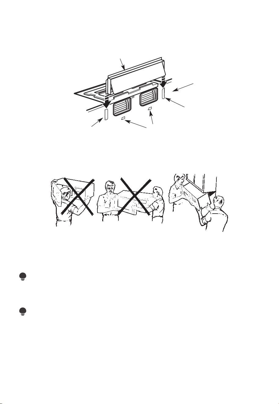
A5. MOUNT THE MICROWAVE OVEN
FOR EASIER INSTALLATION AND PERSONAL SAFETY, WE RECOMMEND THAT TWO
PEOPLE INSTALL THIS MICROWAVE OVEN.
IMPORTANT: Do not grip or use the handle or heat shield during installation. Do not
remove the cardboard spacers between the heat shield and door.
NOTE:
If your cabinet is metal, use the nylon grommet around the power cord hole to prevent
cutting of the cord.
EN-30
NOTE:
We recommend using filler blocks if the cabinet front hangs below the cabinet bottom
shelf.
IMPORTANT: If filler blocks are not used, case damage may occur from overtightening
screws.
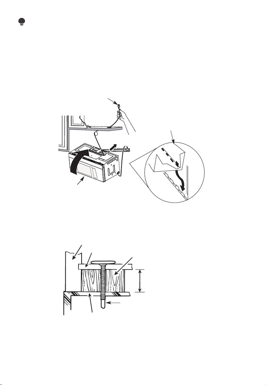
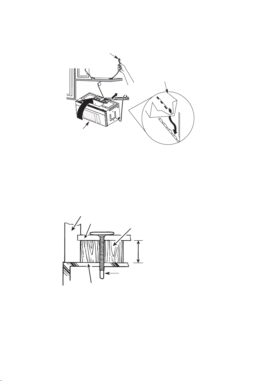
NOTE: When mounting the
microwave oven, thread power
cord through hole in bottom of
top cabinet. Keep it tight
throughout steps 1-3. Do not
pinch cord or lift oven by
pulling cord.
1. Lift microwave, tilt it
forward, and hook slots
at back bottom edge
onto four lower tabs of
mounting plate.
2 Rotate front of oven up
against cabinet bottom.
3. Insert a self-aligning screw through top center cabinet hole. Temporarily secure the
oven by turning the screw at least two full turns after the threads have engaged. (It
will be completely tightened later.) Be sure to keep power cord tight. Be careful not to
pinch the cord, especially when mounting flush to bottom of cabinet.
Microwave Oven Top
Cabinet Front
Cabinet Bottom Shelf
Filler Block
Equivalent to Depth
of Cabinet Recess
Self-Aligning Screw
4. Attach the microwave oven to the top cabinet.
EN-31
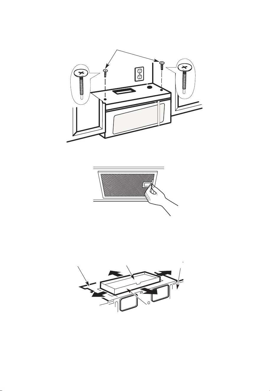
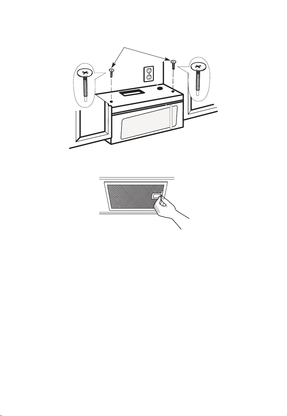
5.
Insert 2 self-aligning screws
through outer top cabinet
holes. Turn two full turns on
each screw.
6. Tighten the outer two screws to the top of the microwave oven. (While tightening
screws, hold the microwave oven in place against the wall and the top cabinet.)
7. Install grease filters. See the Use & Care Guide packed with the microwave.
A6. ADJUST THE EXHAUST ADAPTOR
Open the top cabinet and adjust the exhaust adapter to connect to the house duct.
For Front-to-Back or Side-
to-Side Adjustment, Slide
the Exhaust Adapter as
Needed
Back of
Blower Plate
Damper
Microwave
EN-32
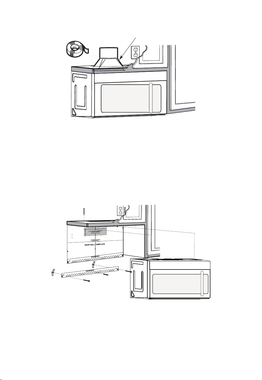
A7. CONNECTING DUCTWORK
House Duct
1. Extend the house duct down to connect to the exhaust adapter.
2. Seal exhaust duct joints using furnace duct tape for high temperature applications
B. OUTSIDE BACK EXHAUST (Horizontal Duct)
INSTALLATION OVERVIEW
B1. Prepare Rear Wall
B2. Remove Blower Plate
B3. Attach Mounting Plate to Wall B4. Prepare Top Cabinet
B5. Adjust Blower
B6. Mount the Microwave Oven
12"
4"
NO
TE
:
REA
D AND F
O
I
T
I
S
V
ER
Y
LLO
I
W
MPO
T
HE
R
D
TA
NT
T
O
IRECTIO
IN THE INSTALLAT
I
O
N
I
NSTRU
CTI
O
N
N
S
S
B
EF
O
RE PR
O
H
T
HTI
W
GN
I
DE
E
C
IS
REAR WA
L
L TEM
PL
A
TE
.
ll Te
mpl
a
te
s
er
v
es
t
o
p
1
ou
a
. Us
mo
u
tle
t.
nti
n
e
a l
T
h
is
R
ea
g
p
r
W
l
a
a
t
e
a
nd
to
lo
ca
te
th
e h
or
iz
o
s
o
n
itio
t
a
n
l e
t
h
xh
e b
au
o
st
t
t
o
m
ioned
to
chec
k tha
t
th
e
t
e
m
pl
at
e
is
p
osit
pl
ark
hol
es
to
ali
gn
wi
th holes
i
n t
he
L
ocat
mounting
RTANT
e and m
:
ate
.
IMP
O
E
AT LEA
THE
CENT
HE LO
CATIO
L
O
C
AT
ERL
INE
ST
.
O
NE STUD
ON EI
F
O
E
DISR
EH
T
SP
AC
E
AREA.
MAR
KT
D TOGGLE
BO
NF
LT
S
O
I
N
R 2 ADD
I
T
THE MO
IO
UN
NA
T
ING
L, EV
EN
L
P
LATE
Y
Trim the
r
e
ar wa
l
l tem
plat
e a
long
the
dott
e
d l
in
e.
k
h
ole
s
to
alig
n w
ith hole
s
in t
he
moun
ti
n
g
Loca
t
e a
n
d
mar
O
RTAN
T
plate.
:
IMP
AT LEA
T
HE CENT
HE
L
O
CATIO
SP
LOCA
T
E
ERLI
N
E
.
I
E
NO
D
U
TSE
NO T
S
T
H
E
R S
ID
E OF
AR
E
A.
MA
RK
ACED
T
T
OG
G
LE B
O
N
F
O
LTS IN
R 2 ADD
I
TION
T
H
E
M
O
UN
A
TING
L,
EV
ENL
P
LATE
Y
Trim the rear
w
al
l t
e
m
pl
a
t
e
a
long
t
he dotted
li
n
e.
3/8"
TO
EDGE
2. L
o
c
c
c
u
a
te
r
a
e
a
t
e
ly
v
nd
el
.
m
a
r
k a
t leas
t
o
d
u
t
s
e
n
o
n
th
r
o t
f
el
e
i
ght
si
d
e of
th
e c
ent
e
r
line
.
r
It is im
port
a
nt
to
us
e
at
l
ea
st
o
n
e
wo
od
sc
rew
mo
ro
unte
d
wa
v
fi
e.
r
M
ml
y
ar
i
k
n
t
a
w
s
o
a
t
ud
d
diti
to
s
up
p
ona
l,
ev
or
en
t
the
w
ly
s
e
pa
ight
ced
e mic
f
e
o
r
s
i
n
t
he
t
h
s
e
u
m
p
pl
ar
k
ied to
ed
l
o
g
c
g
le bo
l
ati
on
t
s
s
.
.
Wh
er
e t
her
e is
lo
o
f
a
c
th
3. Dr
a
th
s
i
tio
at
ll
tu
n
h
d
s
ol
d
ri
l
l
a
3/1
6"
h
ol
e fo
r
w
oo
d
sc
r
e
ws.
F
o
r
h
ol
es
do
,
ht
i
w
p
u
e
a
st
u
d,
d
ril
l
5
/8
" h
ol
es
fo
r
e b
o
n
o
lts
t
li
n
.
NO
T
t
oggl
IN
STAL
L
T
H
E
MO
U
N
TI
NG
PL
ATE
AT
4.
R
e
T
m
HI
S
T
D
O
th
IME.
e te
o
v
e
mpla
te fr
omth
e r
ea
r
wall
.
5.R
e
v
ie
w
the In
s
ta
ll
a
tsnIn
o
i
t r
uc
t
i
on b
o
o
k
for y
o
ur
ins
ta
lla
t
io
n s
it
ua
tio
n
.
Dar
le
vu
el
t
a
ala
ho
japa
raco
ns
ul
tar
la
v
e
rs
i
ón
en
Espa
ño
l.
IMPORTANT NOTES:
1. Make sure the screws for the blower motor and blower plate are securely tightened
when they are reinstalled. This will help pre-vent excessive vibration.
2. Make sure the motor wiring has been properly routed and se-cured and that the wires
are not pinched.
EN-33
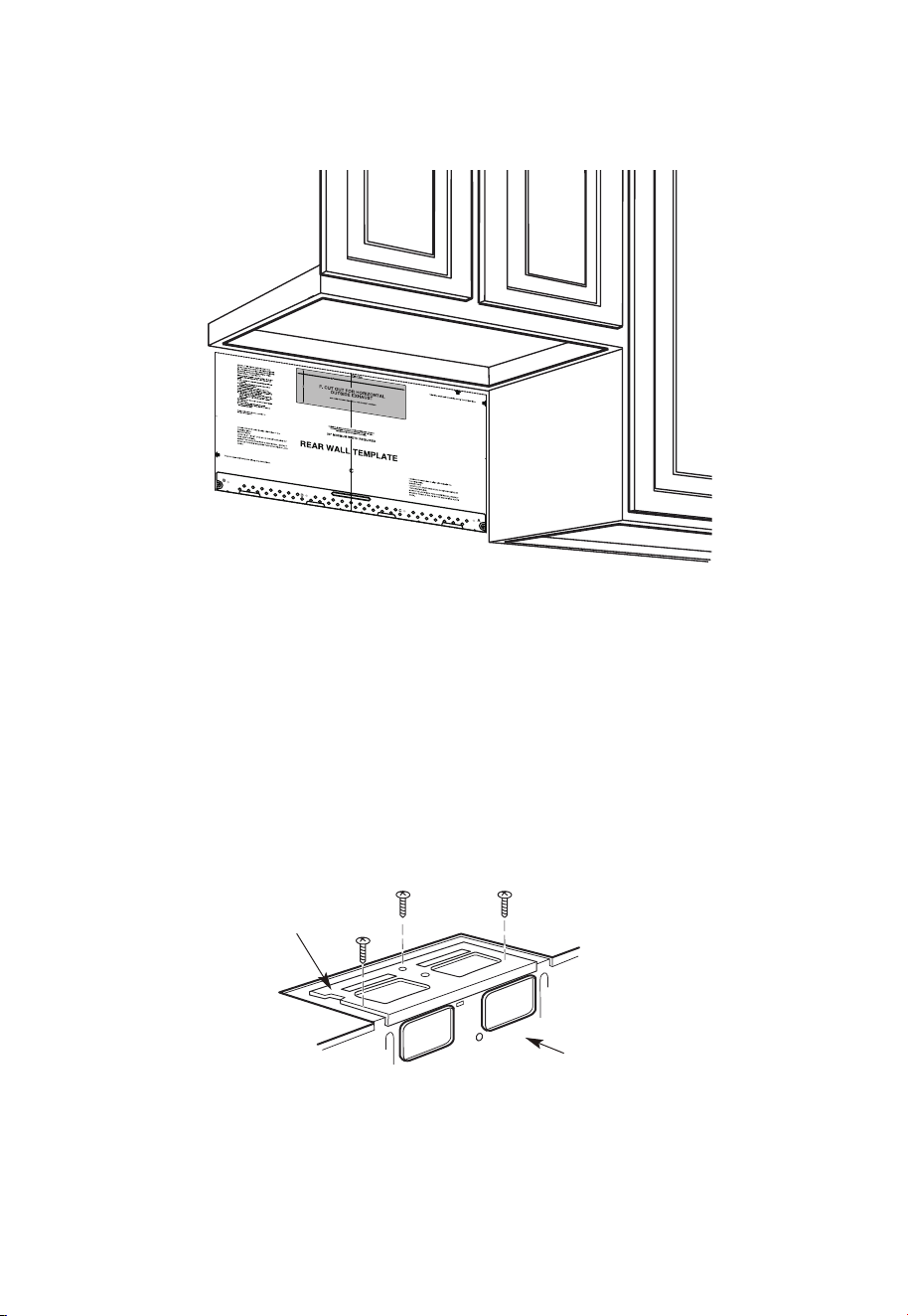
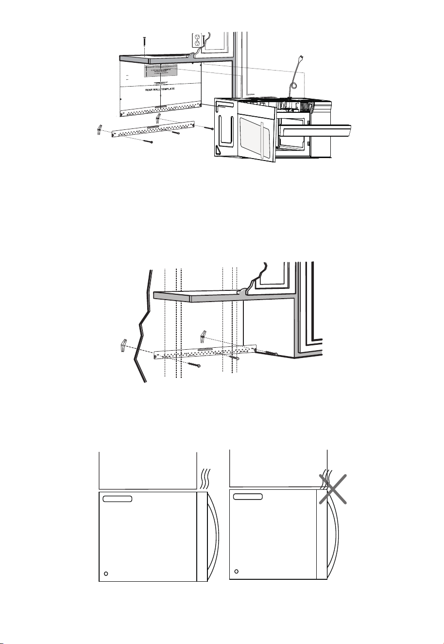
B1. PREPARING THE REAR WALL FOR OUTSIDE BACK EXHAUST
You need to cut an opening in the rear wall for outside exhaust.
1. Read the instructions on the REAR WALL TEMPLATE. Tape it to the rear wall.
2. Cut the opening, following the instructions of the
3. REAR WALL TEMPLATE.
B2. REMOVE BLOWER PLATE
Remove and save the screw that holds the blower plate to the microwave. Lift off the
blower plate.
Microwave
Back of
Blower Plate
EN-34
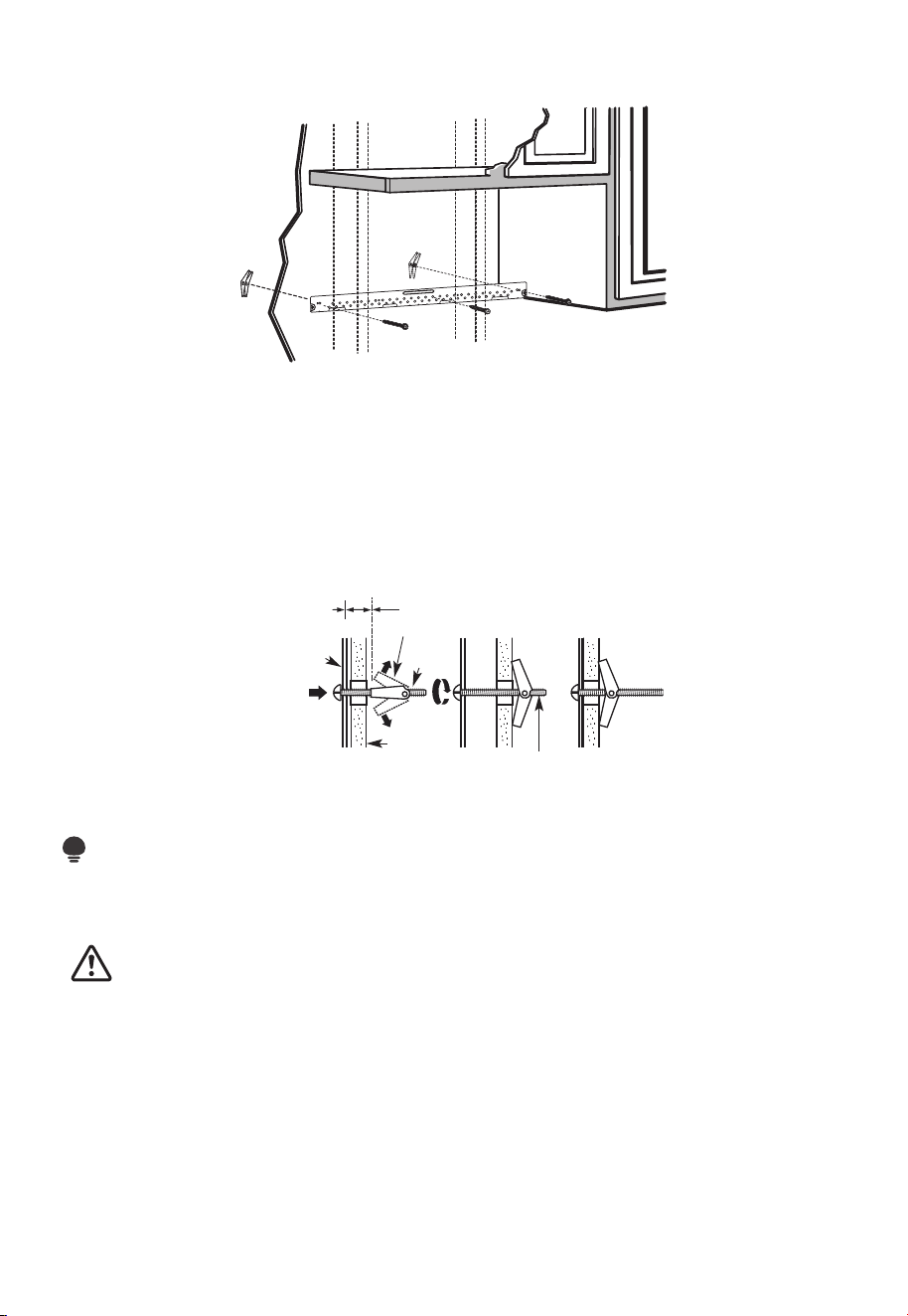
B3. ATTACH THE MOUNTING PLATE TO THE WALL
Attach the plate to the wall using toggle bolts. At least one wood screw must be used to
attach the plate to a wall stud.
1. Remove the toggle wings from the bolts.
2. Insert the bolts into the mounting plate through the holes designated to go into
drywall and reattach the toggle wings to 3⁄4" (19 mm) onto each bolt.
To use toggle bolts:
Wall
Mounting
Plate
Bolt End
Spacing for Toggles
More Than Wall
Thickness
Toggle
Bolt
Toggle Wings
3. Place the mounting plate against the wall and insert the toggle wings into the holes in
the wall to mount the plate.
NOTE:
Before tightening toggle bolts and wood screw, make sure the bottom of the mounting
plate touch the bottom of the cabinet when pushed flush against the wall and that the
plate is properly centered under the cabinet.
CAUTION:
Be careful to avoid pinching fingers between the back of the mounting plate and the
wall.
4. Tighten all bolts. Pull the plate away from the wall to help tighten the bolts.
EN-35
1. Read the instructions on the TOP CABINET TEMPLATE.
2. Tape it underneath the top cabinet.
3. Drill the holes, following the instructions on the TOP CABINET TEMPLATE.
CAUTION:
Wear safety goggles when drilling holes in the cabinet bottom.
B5. ADAPTING MICROWAVE BLOWER FOR OUTSIDE BACK EXHAUST
1. Remove and save screw that holds blower motor to microwave.
Back of
Microwave
Blower Motor
Screw
Blower Motor
2. Carefully pull out the blower unit. The wires will extend far enough to allow you to
adjust the blower unit.
End B
End A
Before: Fan Blade
Openings Facing
Forward
B4. USE TOP CABINET TEMPLATE FOR PREPARATION OF TOP CABINET
You need to drill holes for the top sup-port screws and a hole large enough for the power
cord to fit through.
EN-36
Back of
Microwave
Back of
Microwave
Before Rotation After Rotation
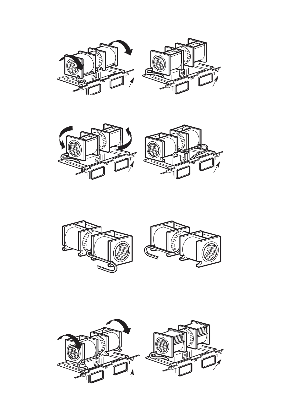
4. Rotate blower unit counterclockwise 180°.
Before Rotation After Rotation
Back of
Microwave
Back of
Microwave
5. Gently remove the wires from the grooves. Reroute the wires through grooves on
other side of the blower unit.
Before Rerouting After Rerouting
Wires Routed
Through Right Side
Wires Routed
Through Left Side
6. Rotate the blower unit 90° so that fan blade openings are facing out the back of the
mi-crowave.
Before Rolling After Rolling
Back of
Microwave
Back of
Microwave
3. Roll the blower unit 90°
EN-37
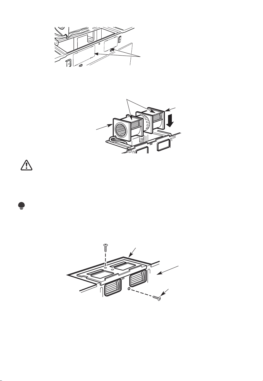
7. Remove the knockout plates in the back of the unit with snips. (for some models)
Knockout Plates:
Snip all 4 webs on
each knockout panel
and remove the metal
knockouts for rear airflow.
Please take care to
remove any sharp edges
created from removing
the knockout plates.
Back of Microwave
8. Place the blower unit back into the opening.
AFTER: Fan Blade
Openings Facing Back
End A
End B
CAUTION:
Do not pull or stretch the blower unit wiring. Make sure the wires are not pinched, and
that they are properly secured.
NOTE:
The blower unit exhaust openings should match exhaust openings on rear of microwave
oven.
9. Secure the blower unit to the microwave with the original screw.
Blower Plate
Blower Motor
Screw
Back of
Microwave
10. Replace the blower plate in the same position as before with the screw. Make sure the
screw is tight.
EN-38
Guide
Guide
Adaptor
Locking Tabs
Back of
Microwave
Push in securely until it is in the lower locking tabs. Take care to assure that the damper
hinge is installed so that it is at the top and that the damper swings freely.
B6. MOUNT THE MICROWAVE OVEN
FOR EASIER INSTALLATION AND PERSONAL SAFETY, WE RECOMMEND THAT TWO
PEOPLE INSTALL THIS MICROWAVE OVEN.
IMPORTANT: Do not grip or use the handle or heat shield during in-stallation. Do not
remove the cardboard spacers between the heat shield and door.
NOTE:
If your cabinet is metal, use the nylon grommet around the power cord hole to prevent
cutting of the cord.
NOTE:
We recommend using filler blocks of the cabinet front hangs below the cabinet bottom
shelf.
IMPORTANT: If filler blocks are not used, case damage may occur from over tightening
screws.
11. Attach the exhaust adaptor to the rear of the oven by sliding it into the guides at the
top center of the back of the oven.
EN-39
NOTE: When mounting the
microwave oven, thread power
cord through hole in bottom of
top cabinet. Keep it tight
throughout steps 1-3. Do not
pinch cord or lift oven by
pulling cord.
1. Lift microwave, tilt it
forward, and hook slots
at back bottom edge
onto four lower tabs of
mounting plate.
2. Rotate front of oven up
against cabinet bottom.
3. Insert self-aligning screw through top center cabi-net hole. Temporarily secure the
oven by turning the screw at least two full turns after the threads have engaged (it will
be completely tightened later). Be sure to keep the power cord tight. Be careful not to
pinch the cord, especially when mounting flush to bottom of cabinet.
Microwave Oven Top
Cabinet Front
Cabinet Bottom Shelf
Filler Block
Equivalent to Depth
of Cabinet Recess
Self-Aligning Screw
4. Attach the microwave oven to the top cabinet.
EN-40
5.
Insert 2 self-aligning screws
through outer top cabinet
holes. Turn two full turns on
each screw.
6. Tighten the outer two screws to the top of the microwave oven. (While tightening
screws, hold the microwave oven in place against the wall and the top cabinet.)
7. Install grease filters. See the Use & Care Guide that came with the microwave for more
information.
C. RECIRCULATING (non vented ductless)
INSTALLATION OVERVIEW
C1. Attach Mounting Plate to Wall
C2. Prepare Top Cabinet
C3. Check Blower Plate
C4. Mount the Microwave Oven
C5. Install or change Charcoal Filter
EN-41
12
"
4"
R
N
O
E
A
T
D
E
:
A
IT
N
I
D F
S
V
E
O
L
R
L
Y
O
I
W
M
P
T
O
H
E
R
T
D
A
I
R
N
E
T
C
T
T
I
O
O
I
N
T
H
E
IN
S
T
A
L
L
AT
I
O
N
I
N
ST
R
U
CT
I
O
N
N
S
S
BE
F
O
RE
P
R
O
C
E
E
D
I
N
G
W
I
T
H
T
H
I
S
R
E
A
R
W
A
LL
T
E
M
P
L
A
T
E
.
T
e
mp
l
a
t
e
s
e
rv
e
s
t
o
p
m
o
t
U
u
l
e
s
n
t
e
.
t
i
1
o
.
u
Th
i
s
R
e
n
a
g
r
p
l
W
a
a
t
e
l
l
a
n
d
t
o
l
o
c
a
t
h
t
e
e
h
o
r
i
z
o
o
s
i
t
n
t
i
o
a
l
n
e
t
x
h
h
e
a
b
u
s
o
t
t
t
o
m
e
t
o
c
h
e
c
k
t
h
a
t
t
h
e
t
e
m
p
l
a
t
e
i
s
p
o
s
i
t
i
o
n
d
L
oc
o
u
n
t
i
n
A
N
T
:
I
m
M
P
O
R
T
E
A
T
L
a
t
e
a
g
n
d
pl
a
m
te
a
.
r
k
h
o
l
es
to
a
li
g
n
w
i
t
h
h
ol
e
s
i
n
t
h
e
LOC
A
T
N
T
E
R
L
E
I
N
A
S
E
.
T
O
NES
T
U
D
O
N
E
I
T
H
E
R
S
ID
E
OF
T
H
E
C
E
H
E
L
O
CA
T
I
SP
AC
E
A
R
EA
.
MAR
K
T
D
TO
G
GLE
B
O
O
L
N
F
T
S
O
I
R
N
2
T
A
H
D
E
DI
M
T
O
IO
U
N
N
T
A
L
I
N
,
E
G
V
P
E
L
N
AT
L
Y
E
o
u
n
t
i
n
:
L
o
c
a
t
e
a
g
n
d
p
lat
m
a
e
.
rk
ho
le
s
t
o
a
l
i
gn
w
i
t
h
h
o
l
e
s
i
n
t
h
e
I
m
M
P
O
R
T
E
A
N
A
T
T
L
LO
C
A
T
NT
E
RL
E
I
A
N
E
ST
.
O
N
E
ST
UD
O
N
E
I
TH
E
R S
IDE
O
F
T
H
E
C
E
H
E
LO
CA
T
I
SP
A
C
A
RE
A
.
M
AR
K
E
D
T
T
O
G
G
LE
B
O
ON
F
L
T
S
O
R
IN
2
T
A
H
D
E
DIT
M
O
I
O
U
N
N
A
T
I
L
,
N
E
G
VE
P
L
A
NL
T
Y
E
T
r
im
t
h
e
re
ar
w
a
l
l
t
e
m
p
lat
e
a
l
on
g
t
h
e
d
o
t
t
ed
l
i
n
e.
3
/
8
"
T
O
EDG
E
Tri
m t
he
re
ar
wa
l
l
t
e
m
pla
t
e along
t
h
e d
ot
t
e
d
l
in
e.
L
a
o
c
c
c
a
u
a
t
r
e
a
t
l
e
v
a
el
n
y
e
d
.
l
2
.
m
a
r
k
a
t
l
e
a
s
t
o
n
e
s
t
u
d
o
n
t
h
e
l
e
f
t
o
r
r
i
g
h
t
s
i
d
e
o
f
t
h
e
c
e
n
t
e
rl
i
n
e
.
I
t
a
t
r
o
p
m
i
s
i
n
t
t
o
u
s
e
a
t
l
e
a
s
t
o
n
e
w
o
o
d
n
t
w
e
a
v
d
f
e
i
.
rm
M
ly
a
r
i
k
n
t
a
w
s
o
t
u
a
d
d
d
t
i
o
t
i
o
s
n
u
a
p
l
,
p
o
e
r
v
t
e
t
h
n
e
l
y
w
s
p
e
i
a
g
h
c
e
t
d
o
o
r
s
i
t
h
n
t
e s
h
u
e
p
m
p
l
a
i
r
e
d
k
e
t
d
o
l
g
o
g
c
l
a
e
t
b
io
o
l
n
t
s
s
.
.
W
h
e
re
t
h
e
r
e
i
s
l
s
3
o
f
o
.
c
r
c
t
t
t
a
D
a
e
h
h
o
t
r
i
e
s
w
g
a
i
l
o
t
t
l
g
u
n
m
l
m
d
h
o
d
s
i
e
o
o
,
c
r
f
l
u
d
e
r
i
l
l
a
3
/
16
"
h
o
l
e
f
o
r
w
o
o
d
s
c
r
e
w
s
.
F
o
r
h
o
l
e
s
n
n
e
u
p
w
it
h
a
s
t
u
d
,
d
r
i
ll
5
/
8
"
h
o
l
e
s
f
o
r
o
l
t
t
N
s
.
l
i
O
D
b
o
T
I
N
S
T
A
L
L
T
H
E
M
OU
N
T
I
N
G
P
L
A
TE
A
T
R
T
H
I
m
S
v
e
T
I
O
M
E
.
4
.
e
o
t
h
e
t
e
m
p
la
t
e
f
r
o
m
t
h
e
r
e
a
r
w
a
l
l
.
5
.
R
e
v
i
e
w
t
h
e
I
n
s
t
a
ll
a
t
i
o
n
In
s
t
ru
c
t
i
o
n
b
o
o
k
f
o
r
y
o
u
r
i
n
s
t
a
l
l
a
t
io
n
s
i
t
u
a
t
i
o
n
.
D
a
r
l
e
v
ue
l
t
a
a
la
ho
j
a
pa
r
a
c
o
n
s
u
l
t
a
r
l
a
v
e
r
s
i
ó
n
e
n
Es
p
a
ñ
o
l
.
IMPORTANT NOTES:
1. Make sure the screws for the blower motor and blower plate are securely tightened
when they are reinstalled. This will help prevent excessive vibration.
2. Make sure the motor wiring has been properly routed and secured and that the wires
are not pinched.
C1. ATTACH THE MOUNTING PLATE TO THE WALL
Attach the plate to the wall using toggle bolts. At least one wood screw must be used to
attach the plate to a wall stud.
If the cabinet depth including the cabinet doors is more than 13", then the unit must be
spaced out from wall using adequate materials supporting 150 Ibs to allow proper top
vent air exhaust/intake.
Cabinet Cabinet
EN-42
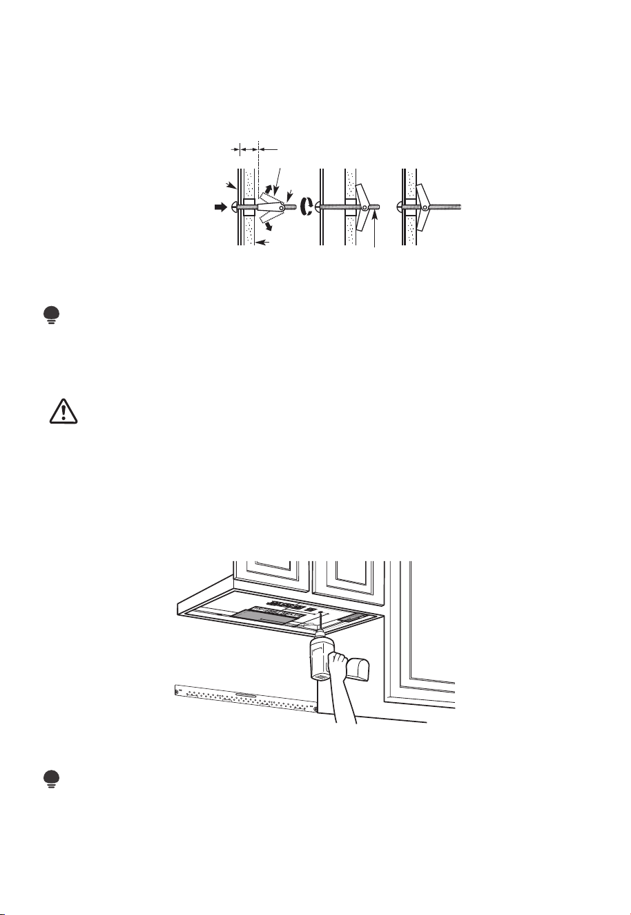
1. Remove the toggle wings from the bolts.
2. Insert the bolts into the mounting plate through the holes designated to go into
drywall and reattach the toggle wings 3/4" to (19mm) onto each bolt.
To use toggle bolts:
Wall
Mounting
Plate
Bolt End
Spacing for Toggles
More Than Wall
Thickness
Toggle
Bolt
Toggle Wings
3. Place the mounting plate against the wall and insert the toggle wings into the holes in
the wall to mount the plate.
NOTE:
Before tightening toggle bolts and wood
screw, make sure the bottom of the mounting plate touch the bottom of the cabinet
when pushed flush against the wall and that the plate is properly
centered under the cabinet.
CAUTION:
Be careful to avoid pinching fingers between the back of the mounting plate and the
wall.
4. Tighten all bolts. Pull the plate away from the wall to help tighten the bolts.
C2. USE TOP CABINET TEMPLATE FOR PREPARATION OF TOP CABINET
You need to drill holes for the top support screws and a hole large enough for the power
cord to fit through.
1. Read the instructions on the TOP CABINET TEMPLATE.
2. Tape it underneath the top cabinet.
NOTE:
Adjust top template accordingly if the microwave is being spaced out from the wall due
to cabinet depth (including cabinet doors) of more than 13".
Drill the holes following instructions on the TOP CABINET TEMPLATE.
EN-43
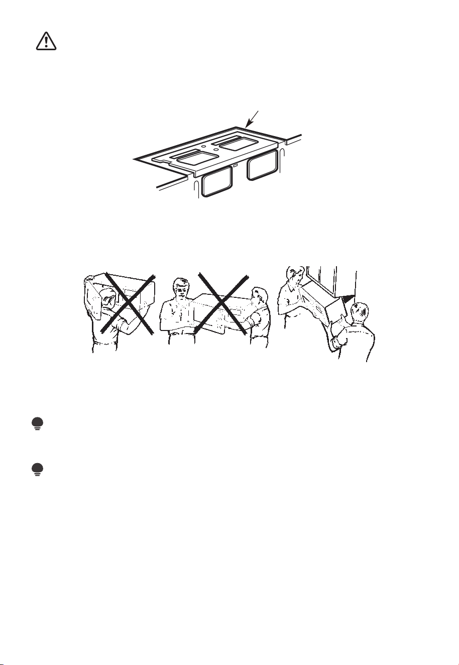
CAUTION:
Wear safety goggles when drilling holes in the cabinet bottom.
C3. CHECK BLOWER PLATE
Blower Plate
Place the microwave in its upright position, with the top of the unit facing up.
Check to see that the blower plate is cor-rectly installed on the unit.
C4. MOUNT THE MICROWAVE OVEN
FOR EASIER INSTALLATION AND PERSONAL SAFETY, WE RECOMMEND THAT TWO
PEOPLE INSTALL THIS MICROWAVE OVEN.
IMPORTANT: Do not grip or use the handle or heat shield during installation. Do not
remove the cardboard spacers between the heat shield and door.
NOTE:
If your cabinet is metal, use the nylon grommet around the power cord hole to prevent
cutting of the cord.
NOTE:
We recommend using filler blocks if the cabi-net front hangs below the cabinet bottom
shelf.
IMPORTANT: If filler blocks are not used, case dam-age may occur from over tightening
screws.
EN-44
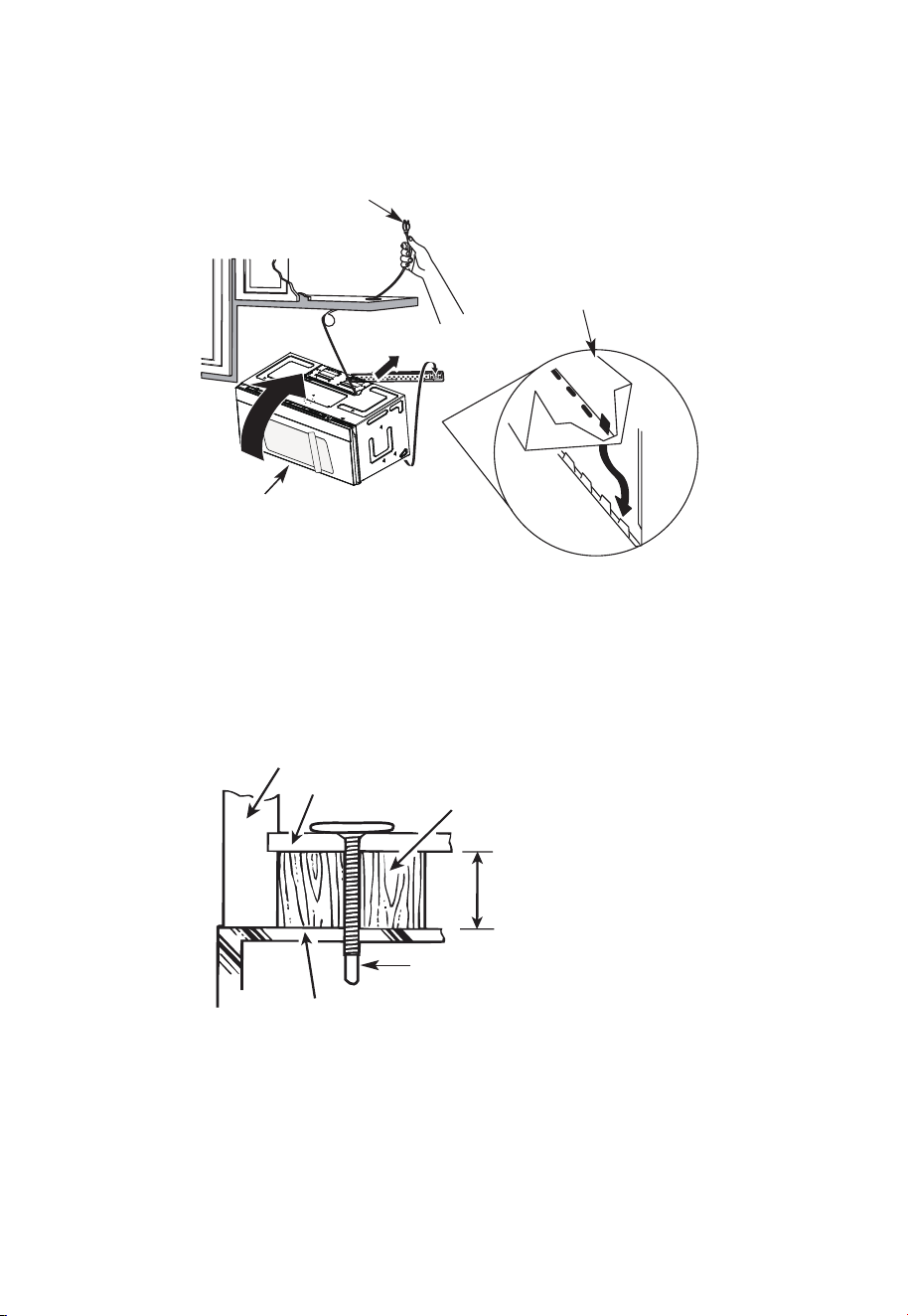
NOTE: When mounting the
microwave oven, thread power
cord through hole in bottom of
top cabinet. Keep it tight
throughout steps 1-3. Do not
pinch cord or lift oven by
pulling cord.
1. Lift microwave, tilt it
forward, and hook slots
at back bottom edge
onto four lower tabs of
mounting plate.
2. Rotate front of oven up
against cabinet bottom.
3. Insert a self-aligning screw through top center cabinet hole. Temporarily secure the
oven by turning the screw at least two full turns after the threads have engaged (It
will be completely tightened later.) Be sure to keep power cord tight. Be careful not to
pinch the cord, especially when mounting flush to bottom of cabinet.
Microwave Oven Top
Cabinet Front
Cabinet Bottom Shelf
Filler Block
Equivalent to Depth
of Cabinet Recess
Self-Aligning Screw
4. Attach the microwave oven to the top cabinet.
EN-45
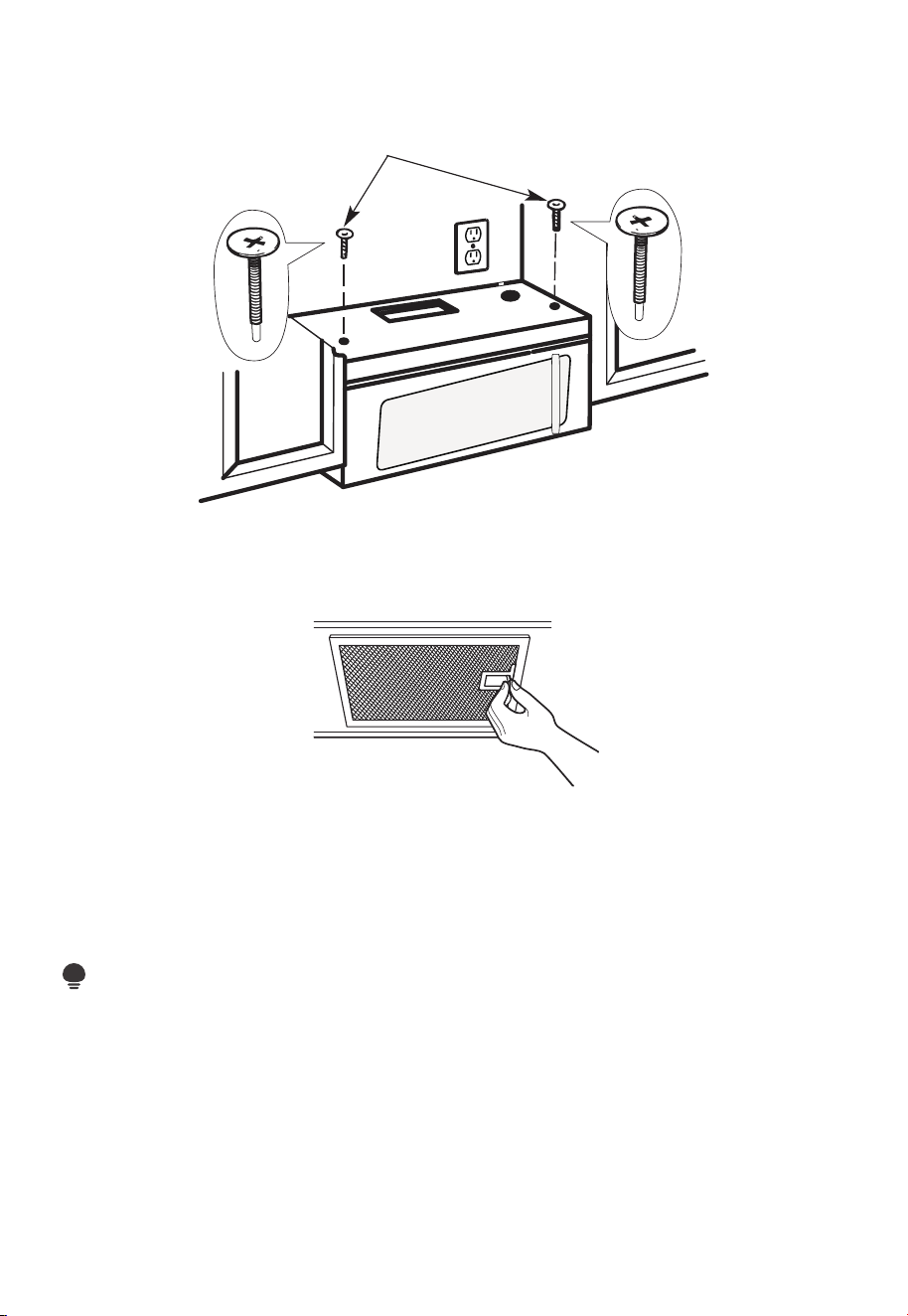
Insert 2 self-aligning screws
through
outer top cabinet holes. Turn two full
turns on each screw.
5
.
6. Tighten the outer two screws to the top of the microwave oven. (While tightening
screws, hold the microwave oven in place against the wall and the top cabinet.)
7. Install grease filters. See the Use & Care Guide packed with the microwave.
C5. INSTALLING OR CHANGING THE CHARCOAL FILTER (Some Models)
NOTE:
The charcoal filter is factory installed in some models. Refer to the Use & Care Guide to
see if yours is factory installed and for replacement information.
For models without the recirculation filter access door, follow these steps to replace or
install a charcoal filter:
1. Unplug microwave oven or disconnect power.
EN-46
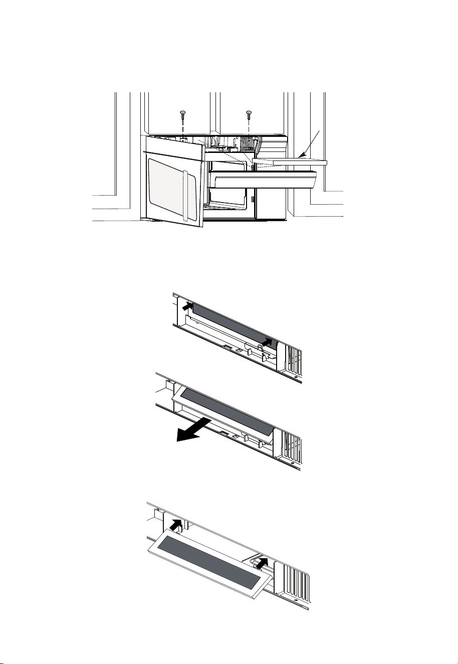
Charcoal
Filter
3. Remove the charcoal filter by pushing the top of the filter inwards,then pull it forward
out from the unit.
4. Slide the top of the new charcoal filter into the top of the filter cavity.
2. Open the microwave door and remove the two vent mounting screws located on top
of the microwave using a #1 Phillips screwdriver.
EN-47
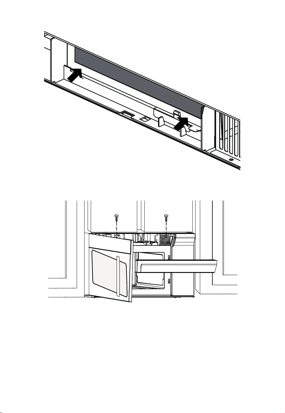
5. Press the bottom of charcoal filter to place it into the correct position.
6. Reinstall the vent by sliding the bottom of the vent into place. Push the vent top into
position and slide right into place. Replace the two vent mounting screws located on
top of the microwave using a #1 Phillips screwdriver.
7. Close the microwave door. Plug in microwave oven or reconnect power.
EN-48
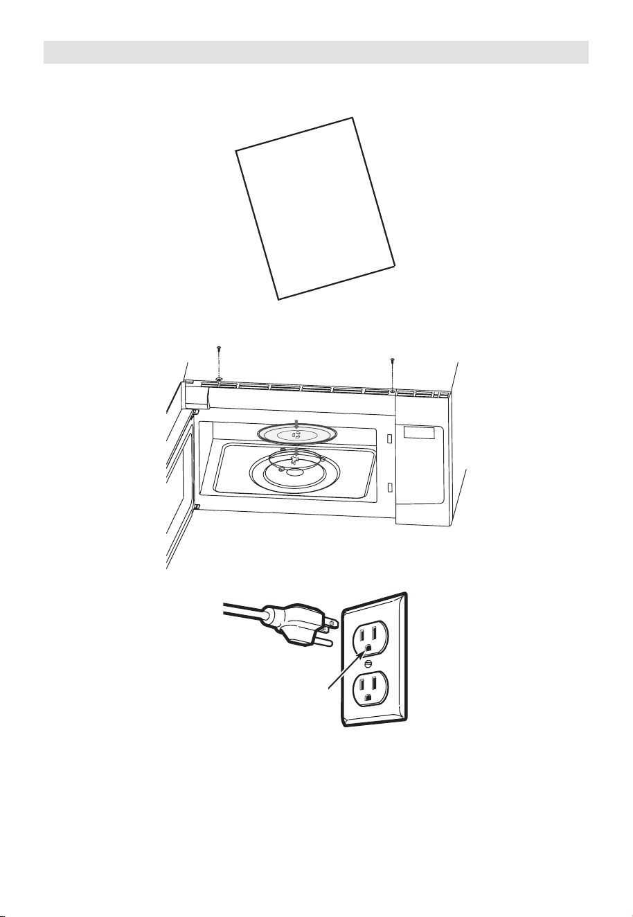
Before You Use Your Microwave
1. Make sure the microwave oven has been installed according to instructions.
2. Remove all packing material from the microwave oven.
3. Install turntable ring and glas stray in cavity.
4. Plug power cord into a seperate and dedicated 15- to 20-amp electrical outlet.
Ensure proper
ground exists
before use
USER
MANUAL
EN-49
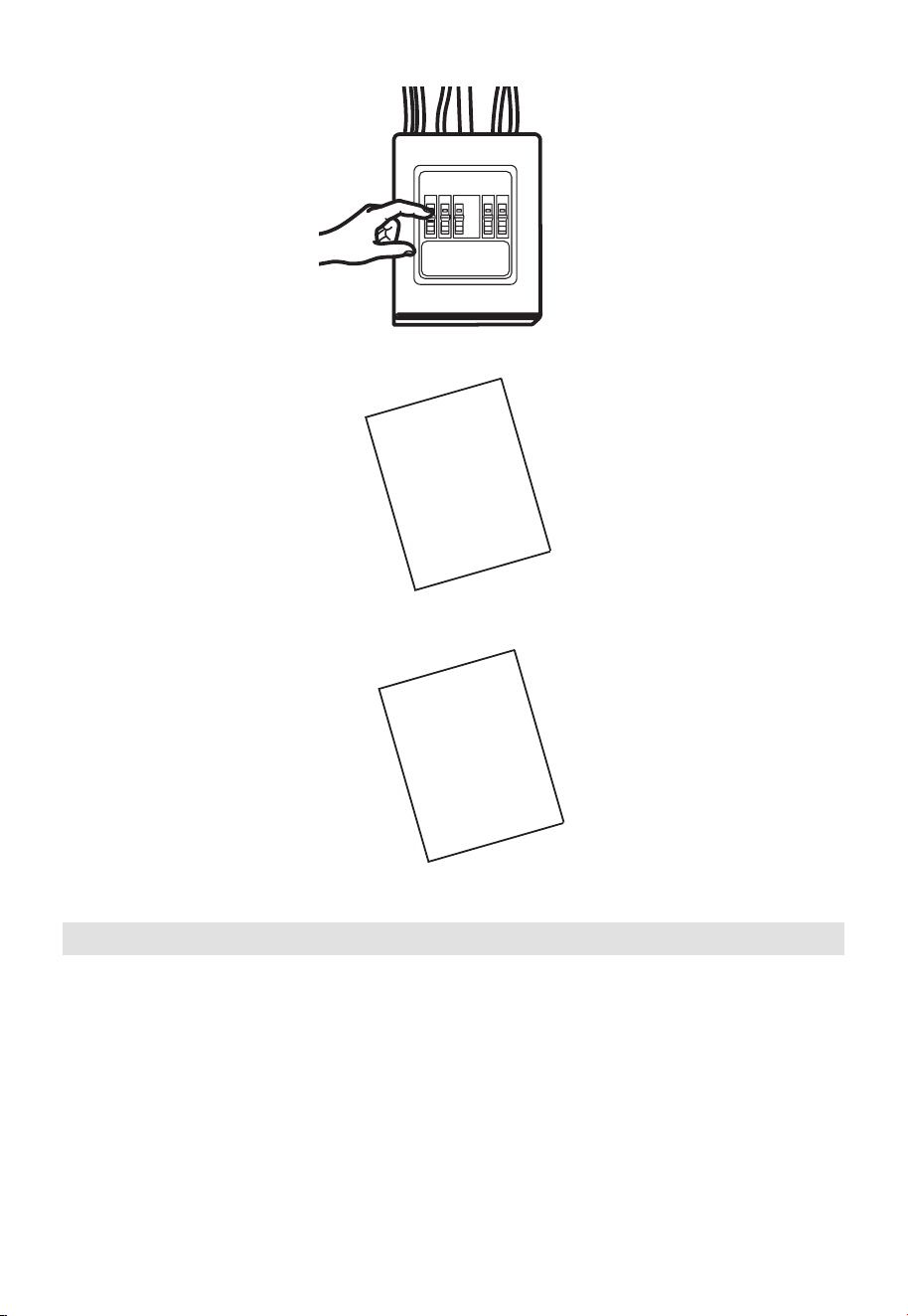
5. Replace house fuse or turn breaker back on.
6. Read the User Manual.
7. KEEP USER MANUAL FOR THE LOCAL INSPECTOR’S USE.
USER
MANUAL
USER
MANUAL
Operational Check
1. Make sure the unit has been installed according to these instructions.
2. Remove all packing materials from the oven.
3. Replace house fuse or turn circuit breaker back on.
4. Plug power cord into receptacle .
5. Read operating instructions before testing the product.
6. Turn on the exhaust fan at Turbo speed and confirm it is operating by using a tissue (it
will stick to the filter).
7. Confirm the outdoor ex-haust flapper has opened.
8. Set the microwave oven for 1 minute and confirm the oven is operat-ing normally using
a cup of water.
9. Keep these installation instruction for the local electrical inspector’s use.
EN-50
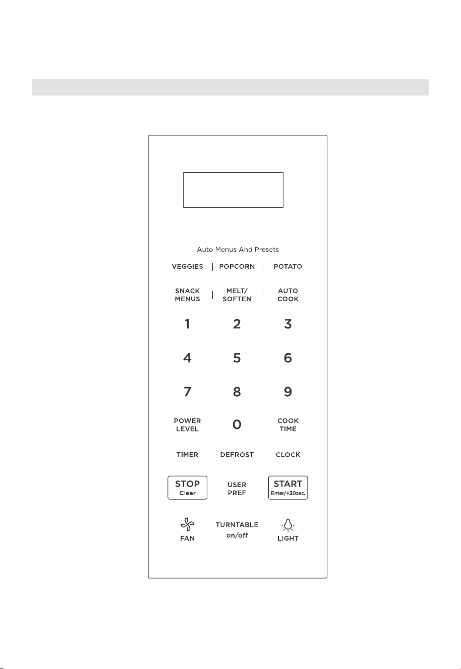
OPERATION INSTRUCTIONS
Control Panel
EN-51
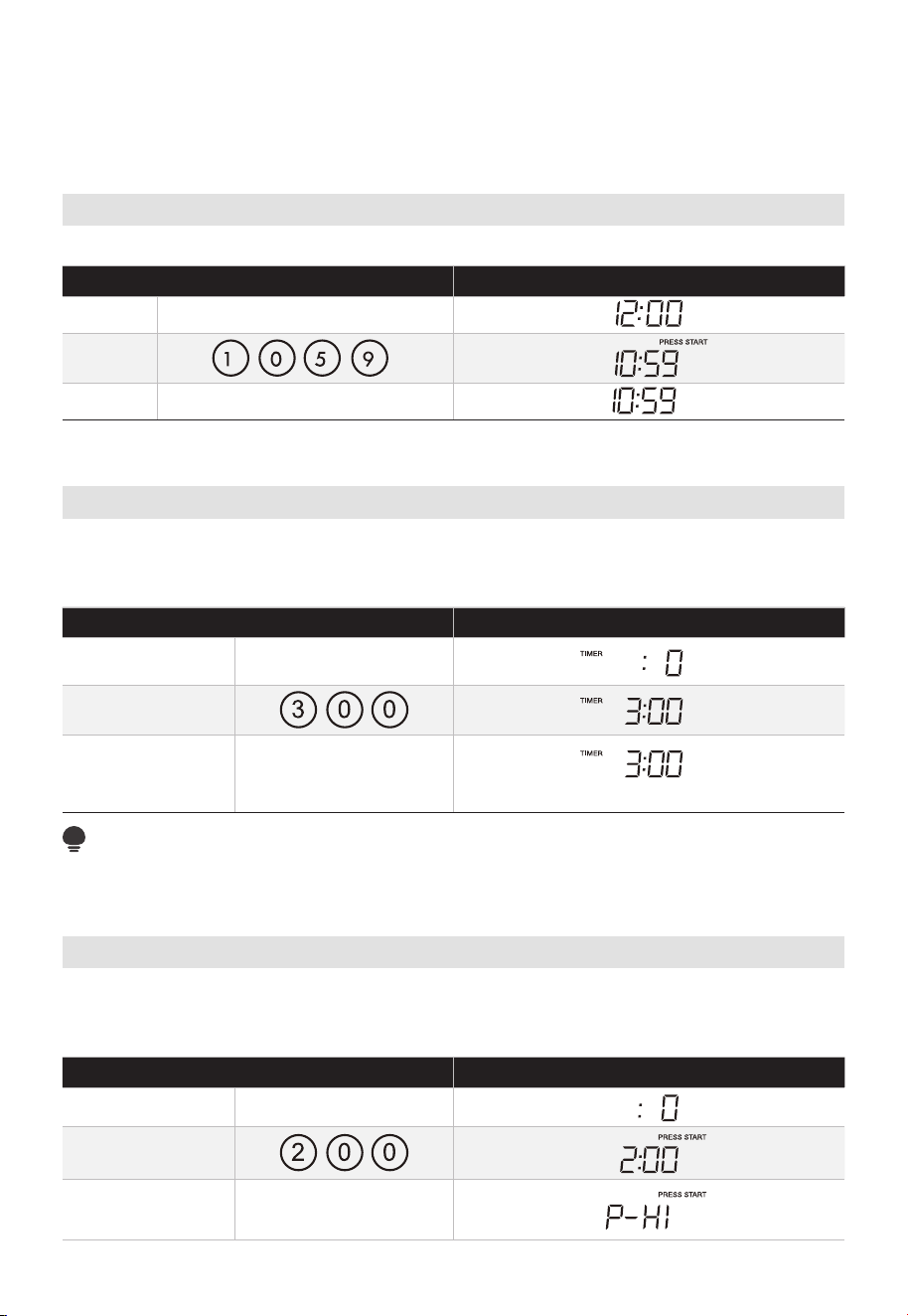
• Before operating your new oven make sure you read and understand this Use and
Care Guide completely.
• The clock can be disabled when the microwave is first plugged in and the S /Clear
Setting The Clock
• Suppose you want to enter the correct time of day 10:59.
TOUCH DISPLAY SHOWS
:
1. CLOCK
2.
3. CLOCK or START/Enter/+30sec.
Setting The Timer
Your microwave oven can be used as a kitchen timer. You can set up to 99 minutes , 99
seconds. The kitchen timer can be used while the microwave oven is running.
• Suppose you want to set for three minutes.
TOUCH DISPLAY SHOWS
:
1. TIMER
2.
3. TIMER
Time counting down
NOTE:
There are not any other programs during the kitchen timer.
Microwave
Your Over the Range Microwave Oven can be programmed for 99 minutes 99 seconds
(99 :99). Always enter the seconds after the minutes, even if they are both zeros.
• Suppose you want to cook for 2 minutes at 90% power
TOUCH DISPLAY SHOWS
:
1. COOK TIME
2.
3.
key is selected. To re-enable the clock follow clock instructions.
TOP
POWER LEVEL X1
EN-52
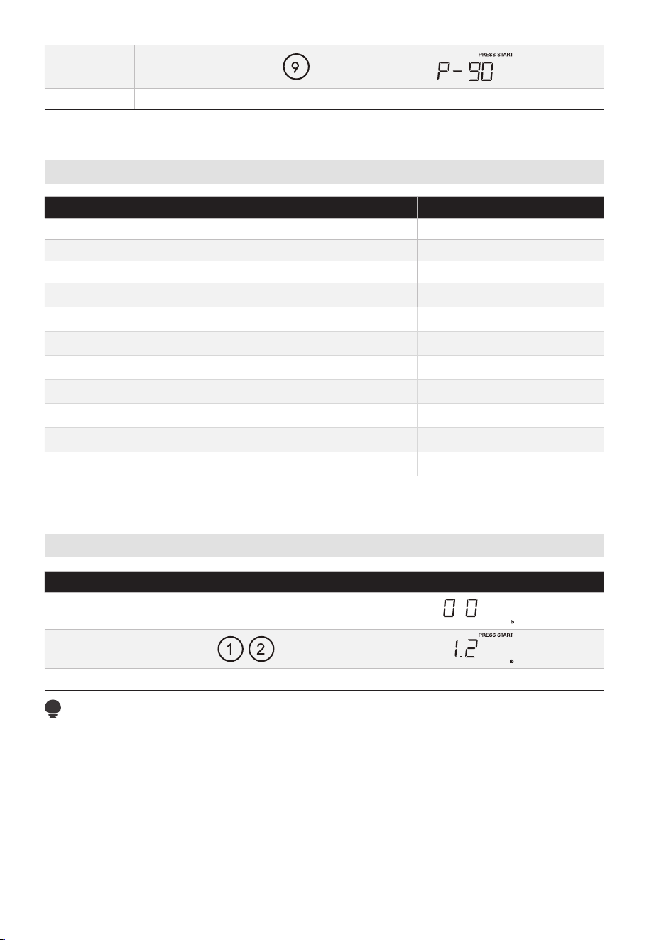
4.
5. Time counting down
Power Chart
PRESS POWER LEVEL DISPLAY
POWER LEVEL x 1 100% P-HI
POWER LEVEL x 2 or 9 90% P-90
POWER LEVEL x 3 or 8 80% P-80
POWER LEVEL x 4 or 7 70% P-70
POWER LEVEL x 5 or 6 60% P-60
POWER LEVEL x 6 or 5 50% P-50
POWER LEVEL x 7 or 4 40% P-40
POWER LEVEL x 8 or 3 30% P-30
POWER LEVEL x 9 or 2 20% P-20
POWER LEVEL x 10 or 1 10% P-10
POWER LEVEL x 11 or 0 0% P-0
Weight Defrost
TOUCH DISPLAY SHOWS
:
1.
2.
3. Time counting down
NOTE:
The weight amount must be a valid entry for this feature to start. A valid weight entry is 0.1
to 6.0 pounds.
DEFROST X1
POWER LEVEL X1 or
START/Enter/+30sec.
START/Enter/+30sec.
EN-53
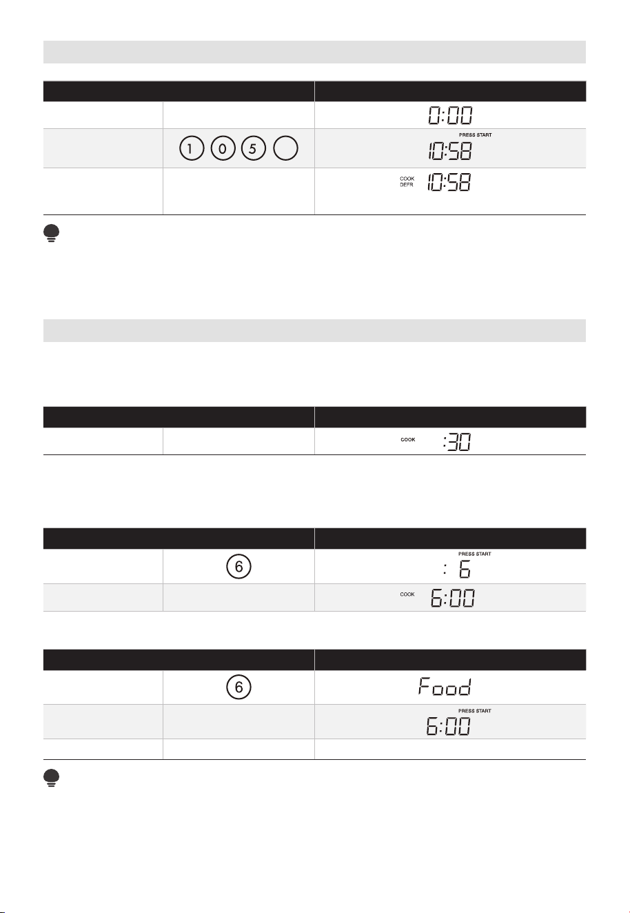
Time Defrost
TOUCH DISPLAY SHOWS
:
1.
2.
8
3.
Time counting down
NOTE:
The buzzer will sound to remind you of turning over the food when half of the time has
passed on.
Speed Cooking
This is a time-saving pad. It is a simplified feature that lets you quickly set and start
microwave cooking at 100% power.
TOUCH DISPLAY SHOWS
:
1.
Press number pads "1-6" to start cooking with corresponding time for 100% power level
directly. For example, cooking with 6 minutes for 100% power level.
TOUCH DISPLAY SHOWS
:
1.
2. After 2 seconds
The oven door should be open d and closed in 5 minutes before the speedy cooking,
operating as below.
TOUCH DISPLAY SHOWS
:
1.
2. open the door
3. Time counting down (Close the door)
NOTE:
"Food" will be displayed if a quick start cooking cycle or "START/Enter/+30sec." key is not
selected within 5 minutes of placing food in the microwave. You must open then close the
door again to clear "Food" from the display.
y
e
DEFROST X2
START/Enter/+30sec.
.
START/Enter/+30sec.
START/Enter/+30sec.
1. Using add 30 seconds:
2. Using number pads for "1-6":
EN-54
otherwise,
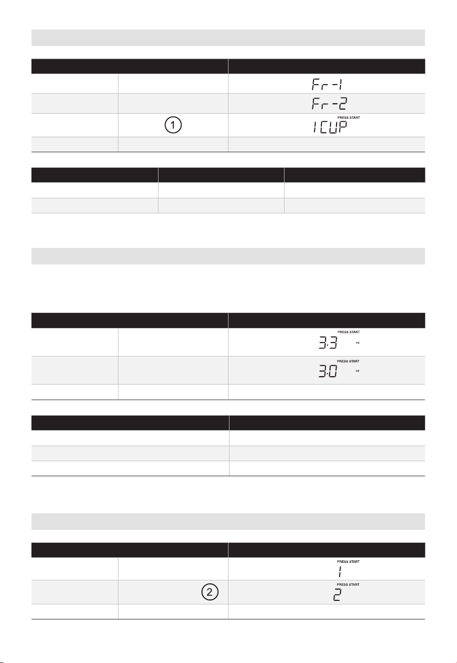
Veggies
TOUCH DISPLAY SHOWS
:
1. VEGGIES X1
Time counting down
PRESS VEGGIES PAD FOOD AMOUNT
X1
Fresh Vegetable 1 - 4 cups
X2
Frozen Vegetable 1 - 4 cups
Popcorn
Press “POPCORN” key and LED displays 3.3 oz. Press “POPCORN” repeatedly to choose
• Suppose you want to cook 3.0 oz. popcorn.
TOUCH DISPLAY SHOWS
:
1.
2. POPCORN X1
3. Time counting down
PRESS POPCORN PAD AMOUNT
X1 3.3 oz
X2 3.0 oz
X3 1.75 oz
Potato
TOUCH DISPLAY SHOWS
:
1. POTATO X1
2. POTATO X1 or
3. Time counting down
3.
4.
the desired weight.
VEGGIES X1
2.
START/Enter/+30sec.
START/Enter/+30sec.
START/Enter/+30sec.
POPCORN X1
EN-55
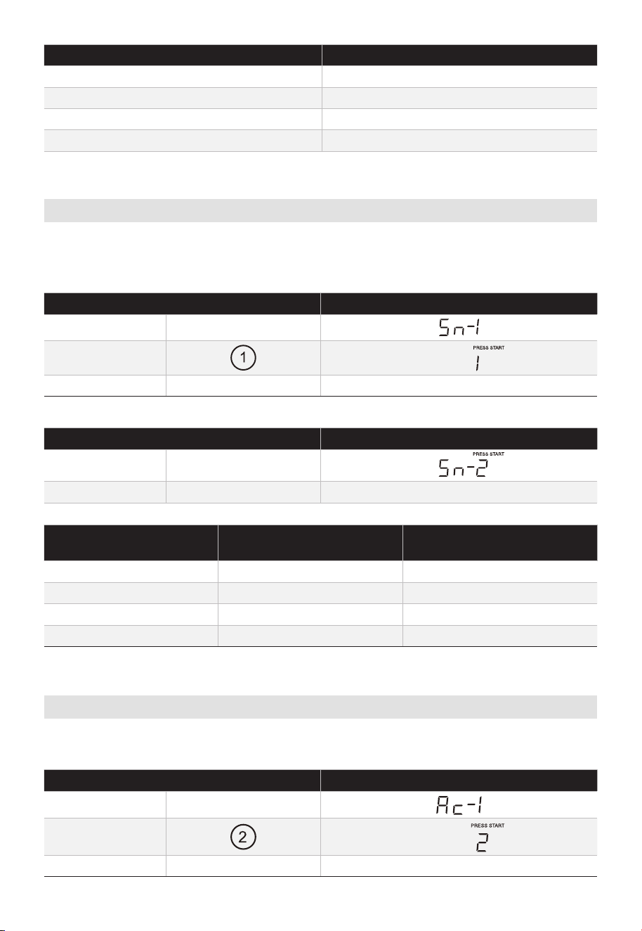
PRESS POTATO PAD OR NUMDER KEYS AMOUNT
X1 1
X2 2
X3 3
X4 4
Snack Menus
There are 4 options (Hot dogs,?? Frozen Kids Meal, Meal In A Cup, Soup) under the snack
menu.
1. Hot dogs or Soup
TOUCH DISPLAY SHOWS
:
1. SNACK MENUS X1
2.
3. Time counting down
2. Frozen Kids Meal or Meal In A Cup
TOUCH DISPLAY SHOWS
:
1.
2. Time counting down
PRESS SNACK MENUS
PAD
FOOD AMOUNT
X1 Hot Dogs 1 - 6 pieces
X2 Frozen Kids Meal 8.8 oz
X3 Meal in a cup 2.39 oz
X4 Soup 1 - 2 cups
Auto Cook
There are 5 options (Bacon, Dinner Plate, Rice, Frozen breakfast, Frozen Pizza) under the
auto cook.
TOUCH DISPLAY SHOWS
:
1. AUTO COOK X1
2.
3. Time counting down
START/Enter/+30sec.
START/Enter/+30sec.
START/Enter/+30sec.
SNACK MENUS X2
EN-56
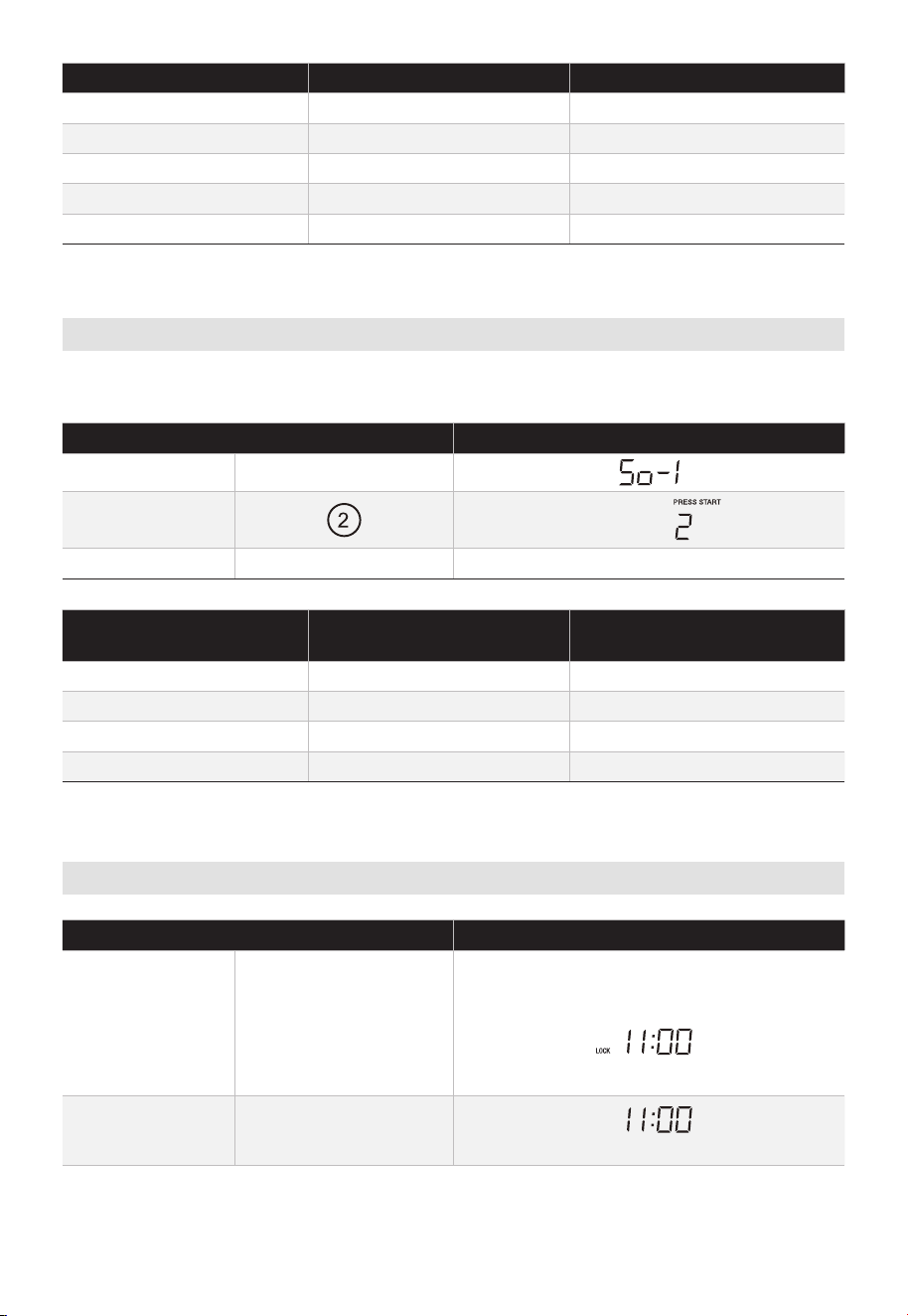
PRESS AUTO COOK FOOD AMOUNT
X1 Bacon 1-3 Slices
X2 Dinner Plate 1-2 Plates
X3 Rice 1-2 Cups
X4 Frozen breakfast 8/12 oz
X5 Frozen Pizza 6/8/12 oz
Melt/Soften
The oven uses low power to melt and soften items. See the following table.
• Suppose you want to melt 2 sticks of Butter.
TOUCH DISPLAY SHOWS
:
1. MELT/SOFTEN X 1
2.
3. Time counting down
PRESS MELT/SOFTEN
PAD
FOOD AMOUNT
X1 Melt Butter 1/2 stick
X2 Melt Chocolate 2/4/8 oz
X3 Soften Ice Cream Pint/1.5Quart
X4 Soften Cream Cheese 3/8 oz
Child Lock
TOUCH DISPLAY SHOWS
:
1.
STOP/Clear
(for 3 seconds)
(if clock is set)
2.
STOP/Clear
(for 3 seconds)
START/Enter/+30sec.
OR
(if clock is set)
LOCK
EN-57
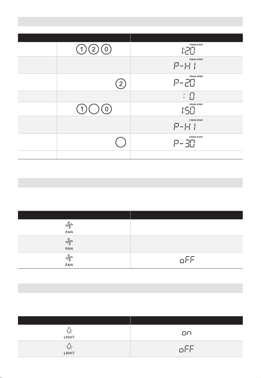
Stage Cook
TOUCH DISPLAY SHOWS
:
1.
2.
3.
4.
5.
5
6.
7.
3
Time counting down
Vent Fan
The pad controls the 2-speed vent fan. If the vent fan is OFF, the first touch of the FAN pad
TOUCH DISPLAY SHOWS
:
X1 VENT HI
X2 VENT LOW
X3\
Light
The pad controls the 2-states light. If the light is OFF, the first touch of the light pad will
turn the light on, second touch OFF.
TOUCH DISPLAY SHOWS
:
X1
X2
8.
\CO\OK TIME
will turn the fan on HIGH, second touch LOW and third touch OFF.
START/Enter/+30sec.
POWER LEVEL X8 or
POWER LEVEL X1
POWER LEVEL X1
POWER LEVEL X7 or
EN-58
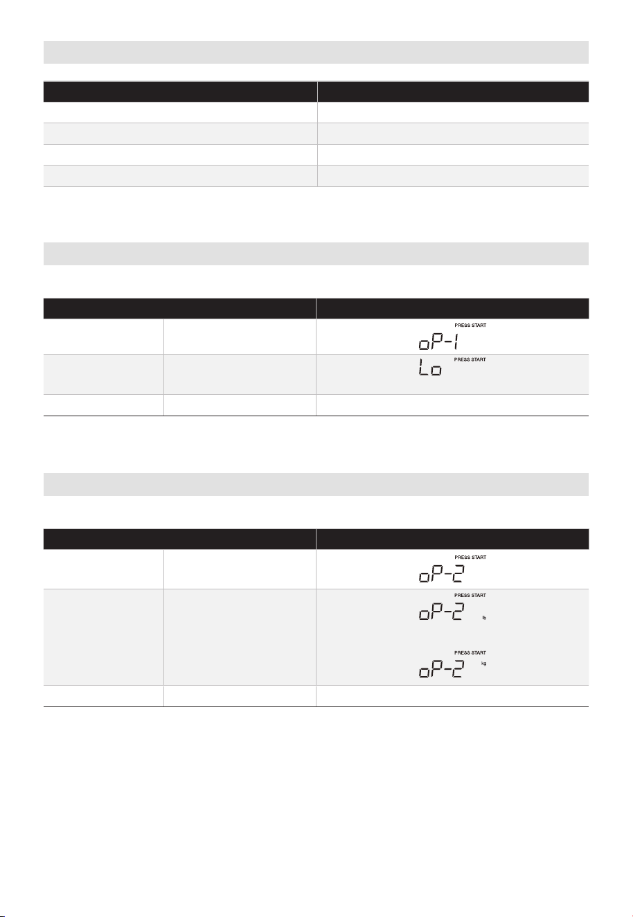
User Pref
KEY SETTING
USER PREF X1 Volume / / /Off
USER PREF X2 Weight lb/kg
USER PREF X3 Clock Display Off/On
USER PREF X4 Demo Mode
Volume
In standby mode:
TOUCH DISPLAY SHOWS
:
1.
USER PREF X1
2.
(Lo, nor, HI, oFF will display in order)
3.
Weight (lb/kg)
In standby mode:
TOUCH DISPLAY SHOWS
:
1. USER PREF X2
2.
or
3.
Lo Nor Hi
START/Enter/+30sec.
START/Enter/+30sec.
START/Enter/+30sec.
START/Enter/+30sec.
EN-59
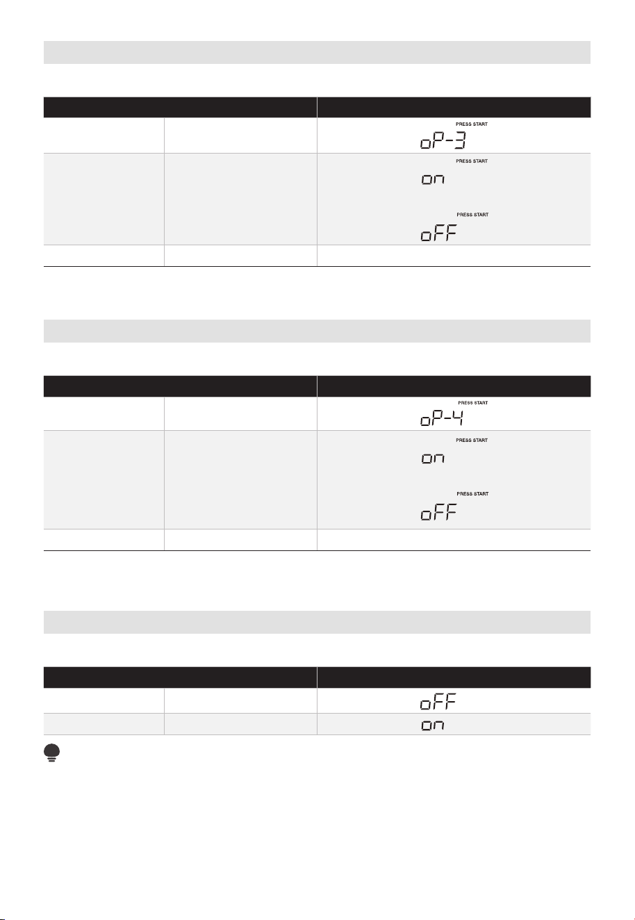
Clock Display O/On
In standby mode:
TOUCH DISPLAY SHOWS
:
1. USER PREF X3
2.
3.
Demo Mode
In standby mode:
TOUCH DISPLAY SHOWS
:
1. USER PREF X4
2.
3.
Turntable On/O
The state default of turntable is on.
TOUCH DISPLAY SHOWS
:
1. TURNTABLE on/off X1
2. TURNTABLE on/off X
NOTE:
The turntable can not be controlled under auto menu and defrost cooking model.
1
START/Enter/+30sec.
START/Enter/+30sec.
START/Enter/+30sec.
START/Enter/+30sec.
or
or
EN-60
TROUBLESHOOTING
Check your problem by using the chart below and try the solutions for each problem. If
the microwave oven still does not work properly, contact the nearest authorized service
center.
TROUBLE POSSIBLE CAUSE POSSIBLE REMEDY
Oven will not start
• Electrical cord for oven is
not plugged in.
• Door is open.
• Wrong operation is set.
• Plug into the outlet.
• Close the door and try
again.
• Check instructions.
Arcing or sparking
• Materials to be avoided
in microwave oven were
used.
• The oven is operated
when empty.
• Spilled food remains in
the cavity.
• Use microwave-safe
cookware only.
• Do not operate with oven
empty.
• Clean cavity with wet
towel.
Unevenly cooked foods
• Materials to be avoided
in microwave oven were
used.
• Food is not defrosted
completely.
• Cooking time, power
level is not suitable.
• Food is not turned or
stirred.
• Use microwave-safe
cookware only.
• Completely defrost food.
• Use correct cooking time,
power level.
• Turn or stir food.
Overcooked foods
• Cooking time, power
level is not suitable.
• Use correct cooking time,
power level.
Undercooked foods
• Materials to be avoided
in microwave oven were
used.
• Food is not defrosted
completely.
• Oven
ventilation ports
are restricted.
• Cooking time, power
level is not suitable.
• Use microwave-safe
cookware only.
• Completely defrost food.
• Check to see that oven
venti- lation ports are
not restricted.
• Use correct cooking time,
power level.
Improper defrosting
• Materials to be avoided
in microwave oven were
used.
• Cooking time, power
level is not suitable.
• Food is not turned or
stirred.
• Use microwave-safe
cookware only.
• Use correct cooking time,
power level.
• Turn or stir food.
EN-61

logo, word marks, trade name, trade dress and all versions thereof are
trademarks, copyrights and other intellectual property rights, and all goodwill derived
from using any part of an Midea trademark. Use of Midea trademark for commercial
purposes without the prior written consent of Midea may constitute trademark
infringement or unfair competition in violation of relevant laws.
This manual is created by Midea and Midea reserves all copyrights thereof. No entity or
individual may use, duplicate, modify, distribute in whole or in part this manual, or
bundle or sell with other products without the prior written consent of Midea.
All the described functions and instructions were up to date at the time of printing this
manual. However, the actual product may vary due to improved functions and designs.
TRADEMARKS, COPYRIGHTS
AND LEGAL STATEMENT
TRADEMARKS, COPYRIGHTS AND LEGAL STATEMENT
valuable assets of Midea Group and/or its affiliates ("Midea"). to which Midea owns
EN-62

DATA PROTECTION NOTICE
For the provision of the services agreed with the customer,
we agree to comply without restriction with all stipulations of applicable data protection
law, in line with agreed countries within which services to the customer will be delivered.
Generally, our data processing is to fulfil our obligation under contract with you and for
product safety reasons, to safeguard your rights in connection with warranty and
product registration questions. In some cases, but only if appropriate data protection is
ensured, personal data might be transferred to recipients located outside of the
European Economic Area.
Further information are provided on request. You can contact our Data Protection
Officer via [email protected]. To exercise your rights such as right to object your
personal date being processed for direct marketing purposes, please contact us via
[email protected]. To find further information, please follow the QR Code.
DATA PROTECTION NOTICE
EN-63


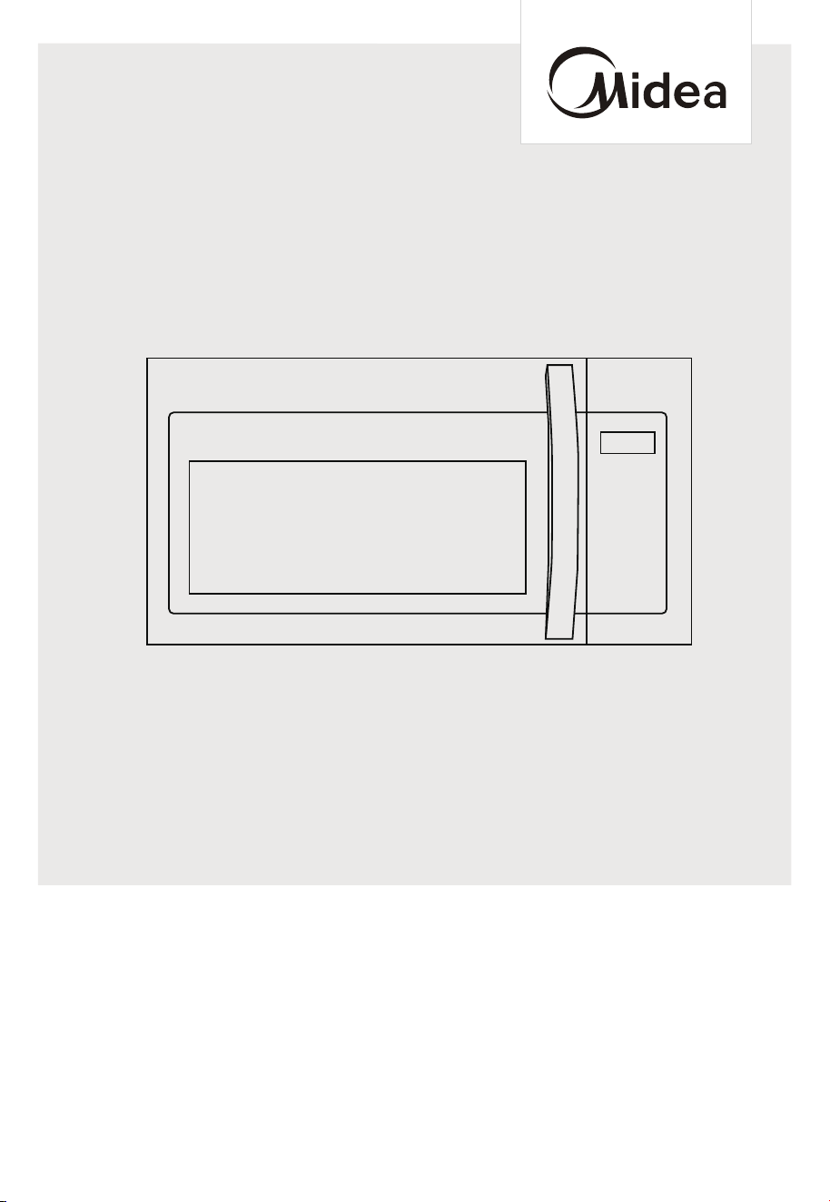
MANUAL DE USUARIO
HORNO MICROONDAS
Avisos de advertencia: Antes de usar este producto, lea detenidamente este manual y guárdelo como
referencia futura.
El diseño y las especificaciones están sujetos a cambio sin previo aviso para la mejora del producto.
Consulte con su distribuidor o fabricante para obtener más detalles.
El diagrama anterior es únicamente de referencia. Por favor, tome como referencia el aspecto del producto real.
MMO17S5AST
MMO17S5AWW
MMO17S5ABB

ES-01
CARTA DE AGRADECIMIENTO ---------------------------------EN-01
INSTRUCCIONES DE SEGURIDAD -----------------------------EN-02
ESPECIFICACIONES----------------------------------------------EN-12
VISTA GENERAL DEL PRODUCTO ----------------------------EN-13
INSTALACIÓN DEL PRODUCTO -------------------------------EN-14
INSTRUCCIONES DE FUNCIONAMIENTO --------------------EN-52
PROBLEMAS Y SOLUCIONES ----------------------------------EN-62
MARCAS REGISTRADAS, DERECHOS DE AUTOR Y
DECLARACIÓN LEGAL ------------------------------------------EN-63
AVISO DE PROTECCIÓN DE DATOS --------------------------EN-64
CONTENIDOS
CARTA DE AGRADECIMIENTO
¡Gracias por elegir Midea! Antes de usar su nuevo producto Midea, lea
detenidamente este manual para asegurarse de que sabe cómo operar las
características y funciones que su nuevo aparato ofrece de forma segura.
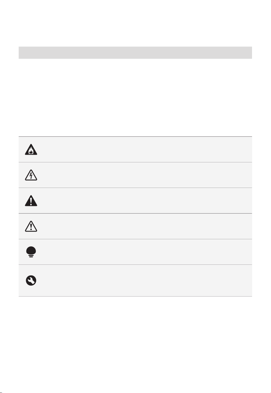
ES-02
INSTRUCCIONES DE SEGURIDAD
Uso Previsto
Las siguientes pautas de seguridad tiene como objetivo evitar riesgos o daños
imprevistos debido al uso inseguro o incorrecto del aparato. Por favor, verifique el
empaque y el producto a su llegada para asegurarse de que todo está intacto para
garantizar un funcionamiento seguro. Si encuentra algún daño, póngase en contacto
con el vendedor o distribuidor. Tenga en cuenta que no se permiten modificaciones o
alteraciones en el aparato por razones de seguridad. El uso no previsto puede causar
peligros y la pérdida de derechos de garantía.
Explicación de Símbolos
Peligro
Este símbolo indica que existen peligros para la vida y la salud de las personas
debido a los gases extremadamente inflamables.
Advertencia de tensión eléctrica
Este símbolo indica que existe un peligro para la vida y la salud de las personas
debido a la tensión.
Advertencia
La señal indica un riesgo de nivel medio que, si no se evita, puede provocar la
muerte o una lesión grave.
Precaución
La señal indica un riesgo de nivel bajo, que si no se evita, puede provocar una
lesión leve o moderada.
Atención
La señal indica información importante (por ejemplo, daños a la propiedad),
perono peligro.
Cumplir con las instrucciones
Este símbolo indica que únicamente un técnico de mantenimiento debe operar
y realizar el mantenimiento de este aparato conforme a las instrucciones de
funcionamiento.
Lea detenidamente estas instrucciones de funcionamiento antes de usar / poner en
funcionamiento la unidad y guárdelas cerca del lugar de la instalación o de la unidad para
un uso posterior.

ES-03
PRECAUCIONES PARA EVITAR
UNA POSIBLE EXPOSICIÓN A
UNA ENERGÍA EXCESIVA DEL
MICROONDAS
a. No intente utilizar este horno con la puerta abierta,
ya que el funcionamiento con la puerta abierta
puede resultar en una exposición nociva a la energía
de microondas.
Es importante no anular ni alterar los bloqueos de
seguridad.
b. No coloque ningún objeto entre el frente del horno
y la puerta ni permita que se acumule suciedad o
residuos de limpiador en las superficies de sellado.
c. No utilice el horno si está dañado. Es especialmente
importante que la puerta del horno cierre
correctamente y que no hayan daños en:
-
PUERTA (doblada)
-
BISAGRAS Y PESTILLOS (rotos o flojos)
-
SELLOS DE PUERTAS Y SUPERFICIES DE
SELLADO
d. El horno no debe ser ajustado ni reparado por nadie
excepto por personal de servicio debidamente
calificado.

ES-04
INSTRUCCIONES IMPORTANTES
DE SEGURIDAD
Al utilizar aparatos eléctricos deben seguirse unas
precauciones básicas de seguridad, incluyendo las
siguientes:
ADVERTENCIA
Para reducir el riesgo de quemaduras, descargas
eléctricas, incendios, lesiones personales o exposición
a energía de microondas excesiva:
• Lea todas las instrucciones antes de utilizar el aparato.
• Lea y siga estos puntos específicos: "PRECAUCIONES
PARA EVITAR LA POSIBLE EXPOSICIÓN A ENERGÍA
DE MICROONDAS EXCESIVA" que se encuentra en la
página 03.
• Este aparato debe conectarse a tierra. Conéctelo
únicamente a un tomacorriente debidamente
conectado a tierra. Consulte "INSTRUCCIONES DE
CONEXIÓN A TIERRA" que se encuentran en la
página 07.
• Instale o ubique este aparato solo de acuerdo con las
instrucciones de instalación suministradas.
• Algunos productos, como huevos enteros y
recipientes sellados, por ejemplo, frascos de vidrio
cerrados, pueden explotar y no deben calentarse en
este horno.
• Utilice este aparato solo para el uso previsto, tal
como se describe en el manual. No utilice productos
químicos o vapores corrosivos en este aparato. Este
tipo de horno está específicamente diseñado para
calentar, cocinar o deshidratar alimentos. No está
diseñado para uso industrial o de laboratorio.
•
LOS CONTENIDOS CALIENTES PUEDEN CAUSAR

ES-05
• No utilice este aparato si tiene el cable o el enchufe
dañado, si no funciona correctamente o si se ha
dañado o se ha dejado caer.
• Este aparato debe ser reparado únicamente por
personal de servicio calificado. Comuníquese con el
centro de servicio autorizado más cercano para su
examen, reparación o ajuste.
• No cubra ni bloquee ninguna abertura del aparato.
• No guarde este aparato al aire libre. No utilice este
producto cerca del agua, por ejemplo, cerca del
fregadero, en un sótano húmedo, cerca de una
piscina o un lugar similar.
• No sumerja el cable ni el enchufe en agua.
• Mantenga el cable alejado de superficies calientes.
• No deje que el cable cuelgue sobre el borde de una
mesa o encimera.
• Cuando limpie las superficies de la puerta y del
horno que se juntan al cerrar la puerta, utilice sólo
jabones suaves y no abrasivos, o detergente aplicado
con una esponja o paño suave.
• Para reducir el riesgo de incendio en el interior del
horno:
-
No sobrecocine los alimentos. Ponga mucho
cuidado y no descuide el aparato cuando coloque
papel, plástico u otros materiales combustibles
dentro del horno para facilitar la cocción.
-
Retire las ataduras de alambre de la bolsa de papel
o plástico antes de introducirlas al horno.
-
Si el material en el interior del horno se enciende,
mantenga cerrada la puerta del horno, apáguelo
y desconecte el cable de alimentación, o corte la
alimentación en el panel de fusibles o disyuntor.
QUEMADURAS GRAVES. NO PERMITA QUE LOS
NIÑOS UTILICEN EL MICROONDAS.
Tenga cuidado al retirar objetos calientes.

ES-06
-
No utilice el interior del horno para guardar
objetos. No deje productos de papel, utensilios de
cocina o comida en el interior del horno cuando no
lo esté utilizando.
• Los líquidos, como el agua, el café o el té, pueden
sobrecalentarse por encima del punto de ebullición
sin que parezca que están hirviendo. No siempre
hay burbujas o ebullición visibles cuando se retira el
recipiente del horno de microondas.
ESTO PODRÍA PROVOCAR LA EBULLICIÓN
REPENTINA DE LÍQUIDO MUY CALIENTE CUANDO
SE AGITA EL RECIPIENTE O SE INTRODUCE UN
UTENSILIO EN EL LÍQUIDO. Para reducir el riesgo de
lesiones a personas:
-
No caliente demasiado el líquido.
-
Revuelva el líquido antes y en la mitad de la
operación de calentamiento.
-
No utilice recipientes con lados rectos y cuellos
estrechos.
-
Después de calentarlo, deje reposar el recipiente
en el horno microondas por un corto tiempo antes
de retirarlo.
-
Tenga mucho cuidado al introducir una cuchara u
otro utensilio en el recipiente.
• No se deben introducir utensilios de metal o de
alimentos de gran tamaño en un horno microondas/
tostador, ya que pueden provocar un incendio o
riesgo de descarga eléctrica.
• No lo limpie con estropajos metálicos. Un fragmento
puede quemar el panel y hacer contacto con partes
eléctricas, ocasionando un riesgo de descarga
eléctrica.
• No utilice productos de papel cuando el aparato esté
funcionando en modo tostador.

ES-07
• No guarde ningún material, excepto los accesorios
recomendados por el fabricante, en este horno
cuando no lo esté utilizando.
• No cubra las rejillas ni ninguna otra parte del
horno con papel de aluminio. Esto provocará el
sobrecalentamiento del horno.
• Limpie las Campanas de Ventilación con Frecuencia -
No deje que la grasa se acumule en la campana o en
el filtro.
• Cuando flamee alimentos debajo de la campana,
encienda el ventilador.
• Tenga cuidado al limpiar el filtro de la campana de
ventilación. Los productos de limpieza corrosivos,
como los limpiadores de hornos a base de lejía,
pueden dañar el filtro.
• Adecuado para el uso en equipos de cocción
eléctricos y a gas.
GUARDE ESTAS INSTRUCCIONES
INSTRUCCIONES DE TOMA A
TIERRA
Este aparato debe conectarse a tierra. En caso de que
se produzca un cortocircuito eléctrico, la toma a tierra
reduce el riesgo de descarga eléctrica ofreciendo
un cable de escape para la corriente eléctrica. Este
aparato está equipado con un cable que tiene un
cable a tierra con un enchufe a tierra. El enchufe
debe conectarse a una toma que esté debidamente
instalada y conectada a tierra.
ES-08
ADVERTENCIA
El uso inadecuado de la conexión a tierra puede
resultar en un riesgo de descarga eléctrica. Consulte
a un electricista o técnico calificado si no comprende
completamente las instrucciones de conexión a tierra
o si tiene dudas si el aparato está correctamente
conectado a tierra o no. Si es necesario utilizar un
cable de extensión, utilice únicamente uno de 3hilos
que tenga un enchufe con conexión a tierra de
3clavijas y un tomacorriente de 3 ranuras que acepte
el enchufe del aparato. La clasificación marcada en
el cable de extensión debe ser igual o mayor que la
clasificación eléctrica del aparato.
PELIGRO
Riesgo de descarga eléctrica
Tocar alguno de los componentes internos puede
provocar graves lesiones personales o la muerte. No
desmonte este aparato.
ADVERTENCIA
Riesgo de descarga eléctrica
Un uso inadecuado de la toma a tierra puede provocar
una descarga eléctrica. No lo enchufe en una toma
hasta que el aparato esté debidamente instalado y
conectado a tierra.
• Se proporciona un cable de alimentación corto para
reducir los riesgos que se derivan de que se enrede o
que se tropiecen con él como con un cable largo.
• Hay juegos de cables más largos o cables de
extensión disponibles que pueden utilizarse siempre
que se haga con cuidado.
• Si se usa un cable de extensión o un cable largo:

ES-09
-
La clasificación eléctrica que aparece marcada en
el juego de cables o el cable de extensión debe ser
como mínimo igual que la clasificación eléctrica del
aparato.
-
El cable de extensión debe ser de tipo a tierra de
3cables.
-
El cable más largo debe colocarse de modo que
no cuelgue sobre el mostrador o la mesa donde los
niños puedan tirar de él o tropezarse sin querer.
INTERFERENCIAS
RADIOELÉCTRICAS
• El funcionamiento del horno microondas puede causar
interferencias en su radio, TV o equipos similares.
• Cuando hay interferencias, se pueden reducir o
eliminar tomando las siguientes medidas:
-
Limpie la puerta y la superficie de sellado del horno
-
Reoriente la antena receptora de radio o televisión.
-
Reubique el horno microondas con respecto al
receptor.
-
Aleje el horno de microondas del receptor.
-
Enchufe el horno de microondas en un
tomacorriente diferente para que el horno de
microondas y el receptor queden en circuitos
derivados diferentes.
ESTE DISPOSITIVO CUMPLE
CON LA SECCIÓN 18 DE LAS
NORMAS DE FCC.

ES-10
UTENSILIOS
PRECAUCIÓN
Riesgo de lesiones personales
Los utensilios herméticamente cerrados podrían
explotar. Los recipientes cerrados deben abrirse y las
bolsas de plástico deben perforarse antes de cocinar.
Véase las instrucciones de « Materiales que puede
usar en el horno microondas o materiales a evitar en el
horno microondas.»
Puede ser que ciertos utensilios no metálicos no sean
seguros para usar en el microondas. Si tiene cualquier
duda, puede probar el utensilio en cuestión siguiendo
el procedimiento que aparece debajo.
Prueba de utensilios:
• Llene un recipiente para microondas con 1 tapa de
agua fría (250 ml) conjuntamente con el utensilio en
cuestión.
• Cocínelo a máxima potencia durante 1 minuto.
• Toque con cuidado el utensilio. Si el utensilio
vacío está caliente, no lo use para el cocinado con
microondas.
• No supere un tiempo de cocinado de 1 minuto.
ES-11
Materiales que puede usar en un horno microondas
Utensilios Comentarios
Plato para
dorar
Siga las instrucciones del fabricante. El fondo del plato para dorar debe
de estar al menos 5 mm (3/16 pulgadas) por encima del plato giratorio.
Un uso incorrecto puede provocar que se rompa el plato giratorio.
Platos y
cubiertos
Solo para microondas. Siga las instrucciones del fabricante. Nouse
platos rajados o astillados.
Jarras de cristal
Retire siempre la tapa. Úselo únicamente para calendar alimentos
hasta que estén calientes.
La mayoría de las jarras de cristal no son resistentes al calor y pueden
romperse.
Cristalería
Utilice únicamente vidrio resistente al calor del horno. Asegúrese de
que no tiene un borde metálico. No use platos rajados o astillados.
Bolsas para
cocina en horno
Siga las instrucciones del fabricante. No lo cierre con un lazo metálico.
Realice rajas para permitir que escape el vapor.
Platos y tazas
de papel
Úselo únicamente para cocinar / calentar a corto plazo. No lo deje sin
atender mientras cocina.
Toallitas de
papel
Use una cubierta alimentaria para recalentar y absorber la grasa.
Úselo con supervisión para la cocina a corto plazo solo.
Papel de
pergamino
Úselo como una tapa para evitar salpicaduras o como un envoltorio
para el vapor.
Plástico
Solo para microondas. Siga las instrucciones del fabricante.
Debe estar etiquetado como « Seguro para microondas ». Algunos
recipientes de plástico se ablandan, a medida de que los alimentos
en su interior se calientan. Las "bolsas de cocción" y las bolsas de
plástico herméticamente cerradas deben cortarse, perforarse o
ventilarse según las instrucciones del paquete.
Envoltorio de
plástico
Solo para microondas. Úselo para cubrir los alimentos durante el
cocinado para retener la humedad. No deje que el envoltorio plástico
toque los alimentos.
Termómetros Únicamente seguros para el microondas (termómetros de carne y dulces).
Papel de cera Úselo como una tapa para evitar salpicaduras y retener la humedad.
Materiales a evitar en el horno microondas
Utensilios Comentarios
Bandeja de aluminio
Puede provocar que se arquee. Transfiera alimentos a un plato
apto para microondas.
Cartón alimentario
con asa de madera
Puede provocar que se arquee. Transfiera alimentos a un plato
apto para microondas.
Utensilios metálicos o
con reborde metálico
El metal protege los alimentos de la energía del microondas.
Elreborde metálico puede causar que se arquee.
Ataduras de alambre
Las ataduras de alambre pueden producir arcos eléctricos y
provocar un incendio en el horno.
Bolsas de papel Pueden causar un incendio en el horno.
Espuma de plástico
La espuma de plástico puede fundirse o contaminar el líquido en
el interior cuando se expone a altas temperaturas.
Madera
La madera se secará cuando se use en el microondas y se puede
dividir o agrietar.

ES-12
ESPECIFICACIONES
MODELO
120VAC 60Hz
1550 W
1000 W
Salida Nominal (Microondas)
Entrada Nominal (Microondas)
MMO17S5AST/MMO17S5AWW/
MMO17S5ABB
Voltaje/Frecuencia Nominal
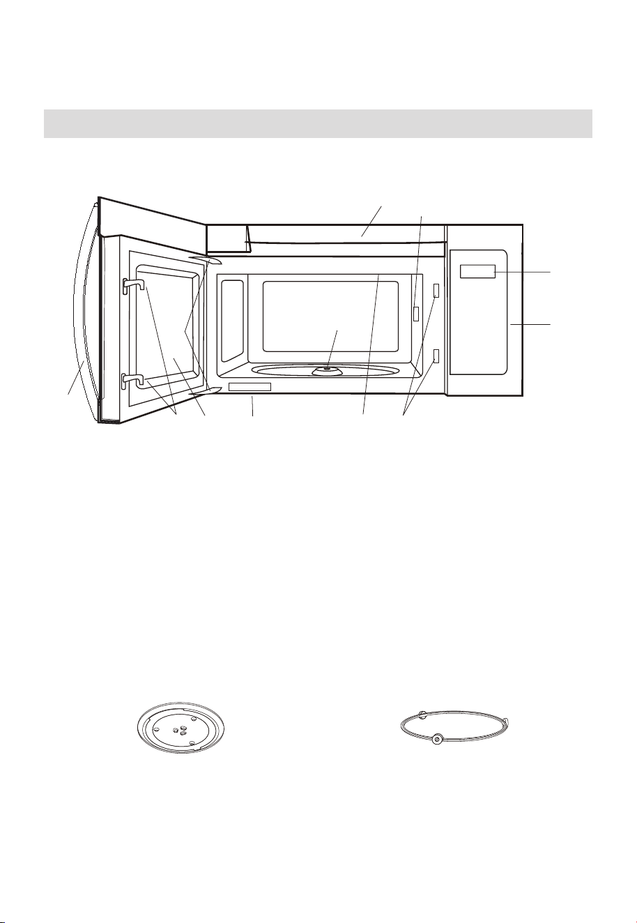
ES-13
VISTA GENERAL DEL PRODUCTO
Configuración de Su Horno
NOMBRES DE LAS PARTES
9
8
10
3
6
4
11
1
2
7
6
5
1. Puerta del horno microondas con ventana transparente
2. Bisagras de las puertas
3. Cubierta de la guía de ondas: NO RETIRAR.
4. Eje del motor del plato giratorio
5. Luz del horno microondas
Se encenderá cuando el horno microondas esté funcionando o la puerta esté abierta.
6. Pestillos de seguridad de la puerta
El horno microondas no funcionará si la puerta no está bien cerrada.
7. Asa
8. Panel de control
9. Pantalla
10. Aberturas de ventilación
11. Etiqueta de clasificación
Plato giratorio de vidrio Conjunto de Anillo de Plato Giratorio
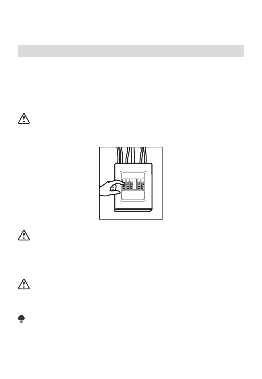
ES-14
INSTALACIÓN DEL PRODUCTO
Instrucciones Importantes de Seguridad
Este producto requiere un tomacorriente con conexión a tierra de tres clavijas.
El instalador debe realizar una verificación de continuidad de tierra en la caja del
tomacorriente antes de comenzar la instalación para asegurarse que la caja del
tomacorriente esté correctamente conectada a tierra. Si no está correctamente
conectado a tierra, o si la caja del tomacorriente no cumple con los requisitos eléctricos
indicados (en REQUISITOS ELÉCTRICOS), se debe contratar a un electricista calificado
para corregir cualquier problema.
PRECAUCIÓN:
Por seguridad personal, retire el fusible o abra el disyuntor de la vivienda, antes de
comenzar la instalación, para evitar lesiones graves o mortales causadas por descarga
eléctrica.
PRECAUCIÓN:
Por seguridad personal, la superficie de montaje debe ser capaz de soportar la carga del
gabinete, además del peso adicional de este producto de 63 a 85 libras (28.5 a 38.5 kg),
más las cargas adicionales que pueda llevar el horno de hasta 50 libras (22.7 kg), o sea
un peso total de 113 a 135 libras (51.3 a 61.2 kg).
PRECAUCIÓN:
Por seguridad personal, este producto no se puede instalar en gabinetes tipo isla o
península. Debe poder montarse TANTO en un gabinete superior COMO en una pared.
NOTA:
Para facilitar la instalación y por seguridad personal, se recomienda que dos personas
instalen este producto.
IMPORTANTE - POR FAVOR LEA DETENIDAMENTE. POR SU SEGURIDAD PERSONAL,
ESTE APARATO DEBE ESTAR CORRECTAMENTE CONECTADO A TIERRA PARA EVITAR
DESCARGAS ELÉCTRICAS SEVERAS O FATALES.
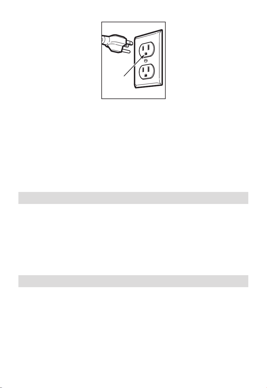
ES-15
Asegúrese de
que haya una
conexión a tierra adecuada
antes de usar el aparato
El cable de alimentación de este aparato está equipado con un enchufe de tres clavijas
(con conexión a tierra) que se acopla a un tomacorriente estándar de tres clavijas
(conconexión a tierra) para minimizar la posibilidad de riesgo de descarga eléctrica de
este aparato.
Debe ponerse en contacto con un electricista calificado para que revise el tomacorriente
y el circuito para asegurarse de que el tomacorriente está conectado a tierra
correctamente.
En caso de encontrar un tomacorriente estándar de dos clavijas, es muy importante
sustituirlo por un tomacorriente de tres clavijas con conexión a tierra, instalado por un
electricista calificado.
EN NINGÚN CASO CORTE, DEFORME O RETIRE NINGUNA DE LAS CLAVIJAS DEL
CABLE DE ALIMENTACIÓN. NO UTILICE CON UN CABLE DE EXTENSIÓN.
Requisitos eléctricos
La clasificación del producto es de 120 voltios AC, 60 Hertz, 15 amperios y 1.55 kilovatios.
Este producto debe conectarse a un circuito de alimentación independiente y dedicado,
con la tensión y frecuencia adecuadas. La dimensión del cable debe cumplir los
requisitos del Código Eléctrico Nacional o el código local vigente para esta clasificación
en kilovatios. El cable de alimentación y el enchufe deben conectarse a un tomacorriente
separado con conexión a tierra de 20 amperios. La caja del tomacorriente debe estar
situada en el gabinete encima del horno microondas. La caja del tomacorriente y el
circuito de alimentación deben ser instalados por un electricista calificado y cumplir con
el Código Eléctrico Nacional o el código local vigente.
Daños durante Transporte/Instalación
1. Si la unidad resulta dañada durante el transporte, devuélvala a la tienda donde la
compró para que la reparen o la cambien.
2. Si la unidad es dañada por el cliente, la reparación o el reemplazo es responsabilidad
del cliente.
3. Si la unidad es dañada por el instalador (no por el cliente), la reparación o el
reemplazo deberá realizarse mediante acuerdo entre el cliente y el instalador.
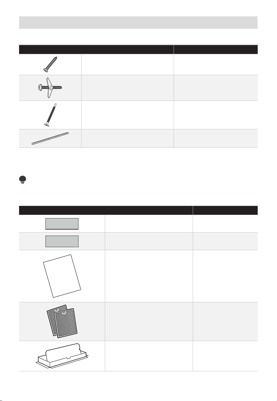
ES-16
Piezas Incluidas
PAQUETE DE HARDWARE
PIEZA CANTIDAD
Tornillos para madera
(
1
⁄
4
" x 2")
2
Pernos de Palanca
(y tuercas de mariposa)
(
3
⁄
16
" x 3")
2
Tornillos de Máquina
Autoalineables
(
1
⁄
4
"-28 x 3
1
⁄
4
")
3
Pasacables de nylon
(para gabinetes metálicos)
1
Encontrará el hardware de instalación en un paquete junto con la unidad. Compruebe
que tiene todas estas piezas.
NOTA:
Se incluyen algunas piezas adicionales.
PIEZAS ADICIONALES
PIEZA CANTIDAD
Plantilla para armario superior 1
Plantilla de Pared Trasera 1
USER
MANUAL
Manual de usuario 1
Filtros de Grasa Empacados
por Separado
2
Adaptador de extracción 1
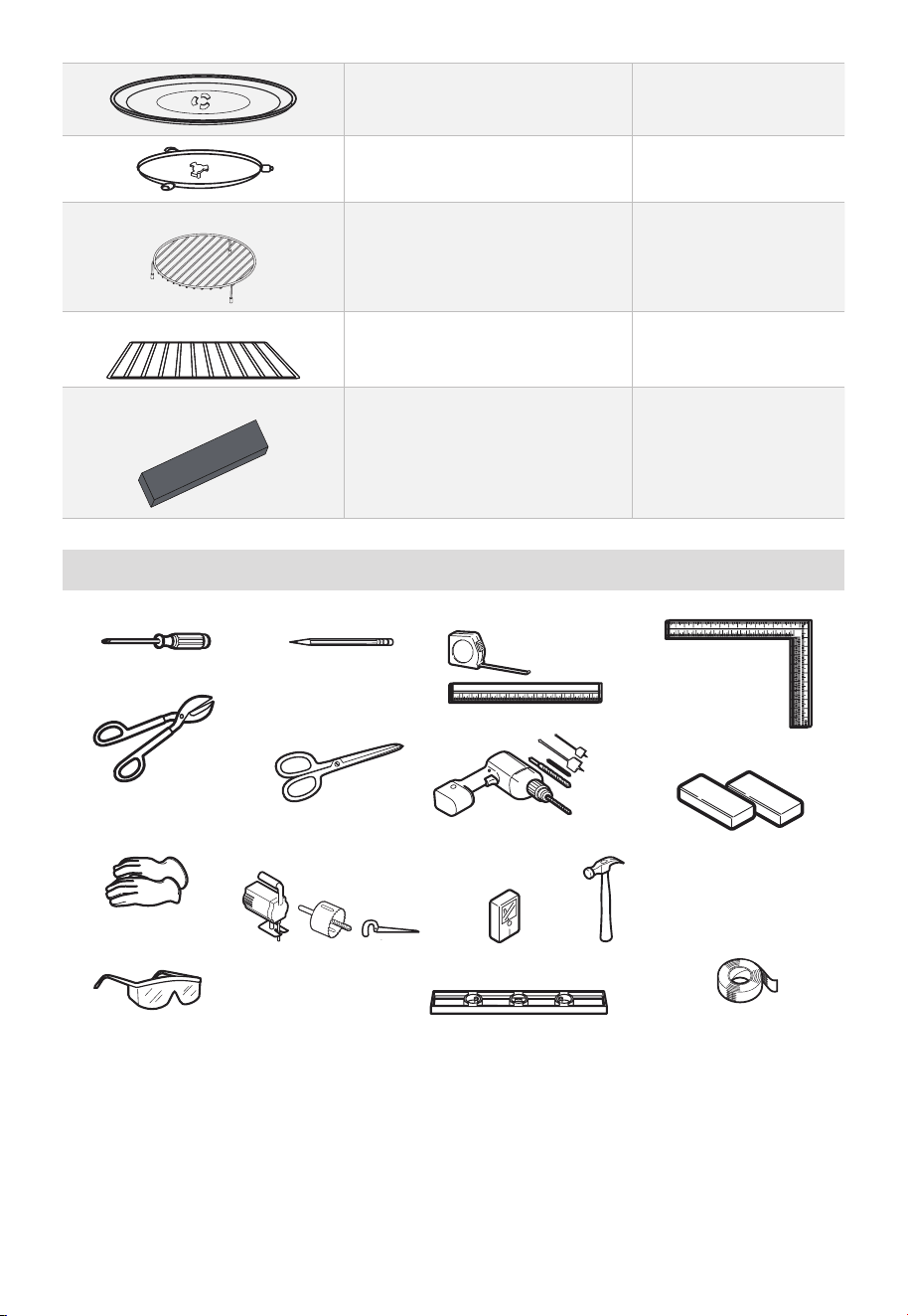
ES-17
Bandeja de cristal 1
Anillo de Plato Giratorio 1
Para algunos modelos
Parrilla de convección 1
Para algunos modelos
Rejilla de división 1
Para algunos modelos
Filtro de Microondas PureAir
®
1
Herramientas Necesarias
Destornillador Phillips # 1 Lápiz
Regla o cinta métrica
Escuadra de
carpintero
(opcional)
Bloques de relleno o
trozos de madera, si
es necesario para el
espaciado del armario
superior (solo se utiliza en
instalaciones de armarios
inferiores empotrados)
Taladro eléctrico con
brocas de
3
⁄
16
“,
1
⁄
2
“
y 5
⁄
8
“
Tijeras
(para cortar la plantilla,
si es necesario)
Cizallas (para cortar
el amortiguador,
siesnecesario)
Guantes
Sierra (de sable, de
orificio o de cerradura)
Detector de clavos o martillo
(opcional)
Cinta adhesiva y de
enmascaramiento
Nivel
Lentes de seguridad
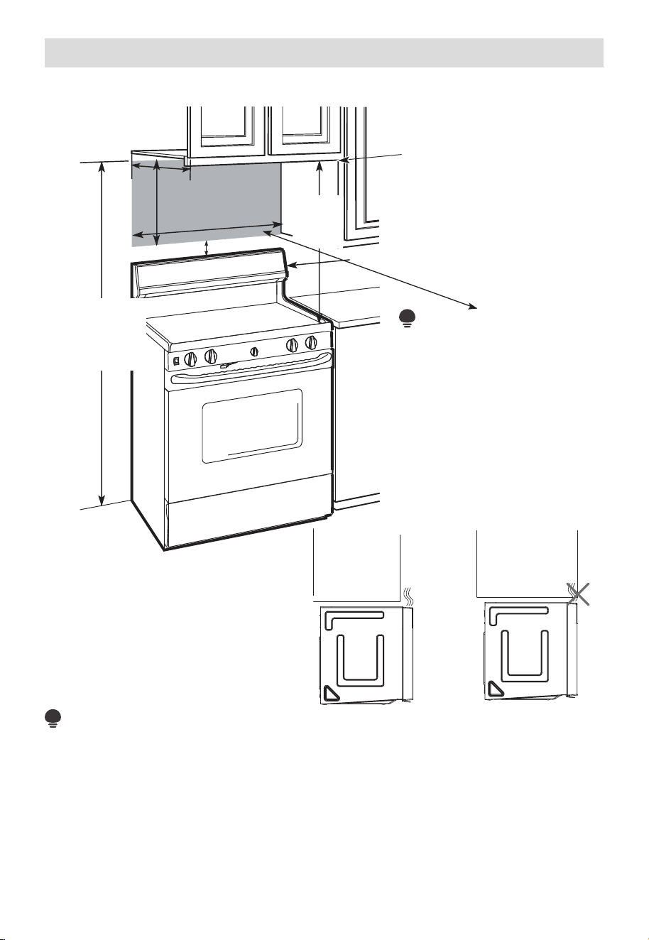
ES-18
Espacio de Montaje
ESPACIO DE MONTAJE
El borde inferior del
armario debe estar
a 30" (76.2 cm) o
más de la superficie
de cocción
66" (167.6 cm)
o más desde el
suelo hasta la
parte superior
del microondas
30"
(76.2cm)
min.
13" máximo (33 cm)
30" (76.2 cm)
16
1
⁄
2
"
(41.9cm)
2" (5.1 cm)
Protector contra salpicaduras
• Si la profundidad del
armario, incluidas las
puertas del armario, es
superior a 13", entonces
la unidad debe separarse
de la pared utilizando
materiales adecuados que
soporten 150 libras para
permitir la salida/entrada
de aire de ventilación
superior adecuada.
NOTA:
NOTA:
• El espacio entre los gabinetes debe ser de 30" (76.2 cm) de ancho y libre de obstrucciones.
• Si va a ventilar su horno microondas hacia el exterior, consulte la Sección de Escape de
Campana para la preparación del conducto de escape.
• Cuando instale el horno de microondas debajo de gabinetes lisos y planos, tenga
cuidado de seguir las instrucciones en la plantilla del gabinete superior para el espacio
libre del cable de alimentación.
• Como guía para la instalación, consulte la página 25 para obtener información sobre la
plantilla de montaje.
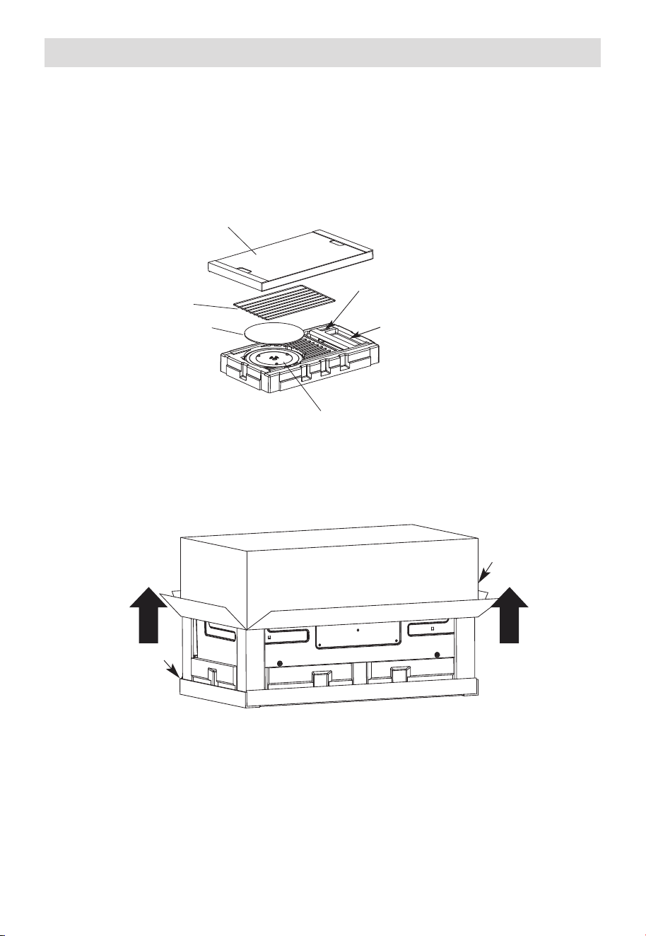
ES-19
1. Colocación de la Placa de Montaje
A. SAQUE EL HORNO MICROONDAS DE LA CAJA/SAQUE LA PLACA DE
MONTAJE
1. Retire la cubierta superior de cartón, las instrucciones de instalación, uso y cuidado,
el adaptador de escape, el anillo del plato giratorio, la rejilla de división, los filtros,
la bandeja de vidrio y la bolsa pequeña de herramientas. No retire la espuma de
poliestireno que protege la parte delantera del horno.
Tablero de cubierta superior
Estante (para
algunos modelos)
Almohadilla EPE
Filtros y anillo giratorio debajo de la bandeja de vidrio
Adaptador de extracción
Bolsa pequeña para herramientas
2. Doble hacia atrás las 4 solapas de la caja completamente contra los lados de la caja. A
continuación, voltee con cuidado el horno y el cartón sobre la parte superior. El horno
debe apoyarse en la espuma de poliestireno.
Espuma de
poliestireno
Cartón
3. Tire de la caja hacia arriba y sáquela del horno.
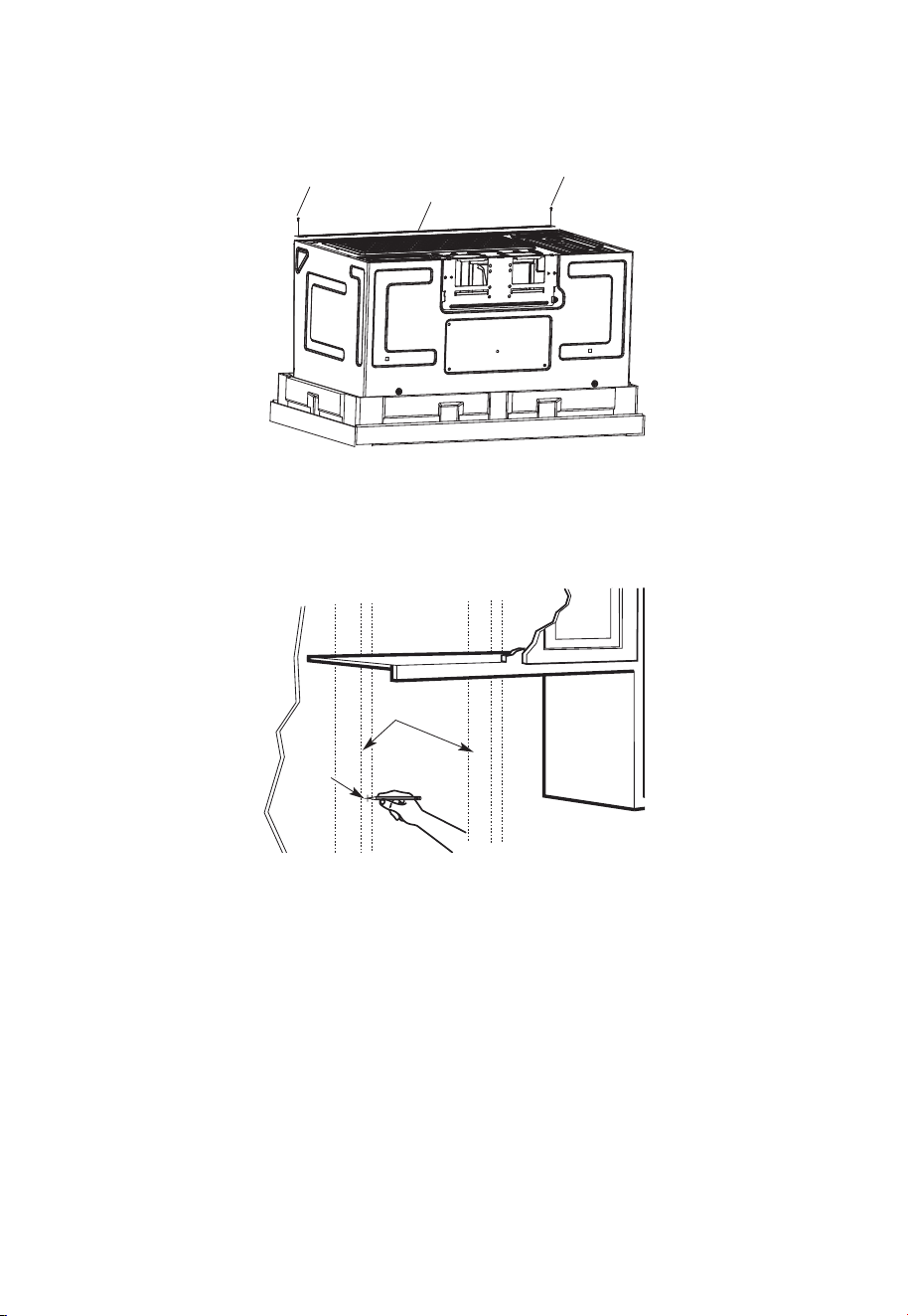
ES-20
4. Corte el centro de la bolsa de plástico protectora exterior para extraer la placa de
montaje
Tornillos
Tornillos
Placa de montaje
5. Retire los tornillos de cada extremo de la placa de montaje. Esta placa se utilizará
como plantilla de la pared trasera y para el montaje. Vuelva a instalar los tornillos en
los orificios de donde se retiraron.
B. ENCONTRAR LAS VIGAS DE LA PARED
Montantes
de pared
Centro
1. Encuentre las vigas, usando uno de los siguientes métodos:
-
Detector de vigas: dispositivo magnético que detecta clavos.
-
Golpee ligeramente con un martillo la superficie de montaje para encontrar un
sonido sólido. Lo cual indicará la ubicación de una viga.
2. Después de ubicar las vigas, busque el centro tanteando la pared con un clavo
pequeño para encontrar los bordes de la viga. Luego coloque una marca en medio
de los bordes. El centro de cualquier viga adyacente debe estar a 16" (40.6 cm) o
24"(61cm) de esta marca.
3. Trace una línea en el centro de las vigas.
EL MICROONDAS DEBE ESTAR CONECTADO AL MENOS A UNA VIGA DE LA PARED.
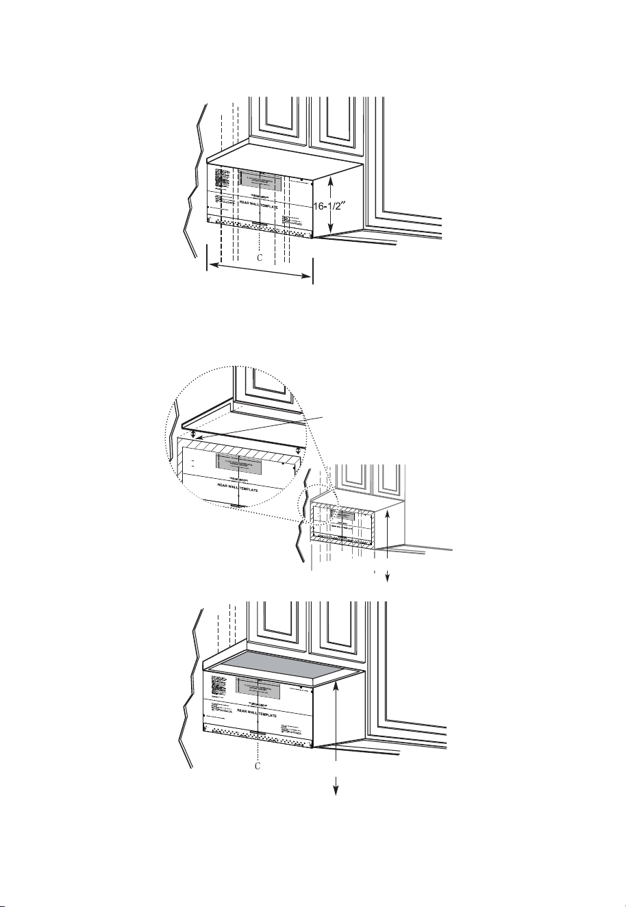
ES-21
C. DETERMINAR LA UBICACIÓN DE LA PLACA DE PARED DEBAJO DE SU
GABINETE
Posición de la placa debajo del gabinete de fondo plano
30" como mínimo
Trace una línea vertical en la pared en el centro del espacio de 30" de ancho.
Pegue con cinta adhesiva la Plantilla de Pared Trasera en la pared haciendo coincidir la
línea central y tocando la parte inferior del gabinete.
Posición de la placa: debajo del gabinete inferior empotrado con voladizo frontal
C
3/
8"
TO
EDGE
N
OT
E:
IT IS VERY IMP
O
RTA
NT
T
O
RE
AD
AND
FO
LL
O
W THE
D
IRE
C
T
I
ON
S
IN
T
H
E
IN
S
T
A
LL
ATI
ON
IN
ST
RUC
TIONS
B
E
F
ORE PR
OCEEDING WIT
H T
HIS
RE
AR W
A
LL
TEMPLATE.
This Re
a
r W
a
ll
Te
mplate
serv
e
s
t
o po
s
itio
n
t
he
bo
tt
om
m
o
u
nting p
la
t
e
a
nd
t
o
lo
ca
t
e
th
e
ho
ri
zo
nt
al
e
xh
au
st
ou
tle
t
.
1.
Use
a
le
ve
l
t
o
ch
eck
th
a
t
t
h
e
t
e
mp
la
te
is
posit
ione
d
a
c
c
u
ra
tely.
2
. Loc
ate
an
d
m
ar
k
at
lea
st
one stud
o
n t
he
le
ft or
ri
ght
sid
e
of the ce
n
te
r
lin
e
.
It
is
import
a
n
t
to use at
l
e
ast one wo
o
d
s
c
rew
mou
n
ted
f
ir
m
ly
in
a
stud
to
s
u
ppor
t the
weig
ht
of t
he
m
ic
r
owave.
M
ark
tw
o additiona
l,
eve
nly
spac
ed
lo
c
atio
ns for
the su
pplied
toggle
bolt
s
.
3.
Dril
l
holes
in
t
he
m
a
rk
e
d
locations.
Where
th
e
re
is
a
stud, drill
a
3
/
16" h
ole
fo
r
woo
d
s
c
rew
s
. F
or
h
o
le
s
th
at d
o
not li
n
e up
w
it
h
a
s
tud,
drill 5/
8
"
holes fo
r
toggle bolts.
DO
NOT INSTALL
T
H
E
MOUN
TIN
G
P
LA
T
E
AT
TH
IS
T
I
M
E
.
4
. R
e
mo
v
e
t
h
e templa
te
from t
he
r
e
ar
wall.
5
.
R
e
v
i
ew th
e
Inst
a
llatio
n
In
st
r
uction
boo
k
fo
r
y
ou
r
in
stalla
tio
n
si
t
uat
io
n
.
L
o
c
ate an
d
mark
ho
l
es
to
align w
ith h
o
les
i
n the
mo
u
n
t
in
g
p
l
ate.
I
MP
ORTANT
:
LO
CATE
AT LEAST ONE
S
TU
D ON EIT
H
ER
S
IDE OF
T
HE CE
NTER
LIN
E.
MA
RK
TH
E
LOCAT
I
ON
FO
R
2
A
DD
ITIONA
L, E
V
E
N
LY
S
P
AC
E
D TOGG
LE B
OL
T
S IN
THE MO
U
N
TIN
G
P
LAT
E
ARE
A.
Lo
cate a
n
d
ma
rk ho
les to
align with holes in
the
mo
unting p
l
a
te.
I
MPO
RTA
N
T:
LOCATE AT
L
E
AST
ONE ST
U
D ON
EI
TH
E
R SID
E
O
F
T
H
E CENTE
RLINE
.
MARK
THE LOCATION
FOR
2 AD
D
I
TI
ON
AL
,
E
V
E
NL
Y
SPACED
TO
GGLE B
OL
T
S IN
THE MO
U
NT
IN
G
PLATE
AR
E
A.
T
r
im
th
e
rea
r
wal
l
temp
late along th
e dotte
d line
.
Trim th
e rear
wa
l
l te
mpl
a
te
a
lo
n
g
th
e
dotted line
.
12"
4"
Da
r
le
vuelta
a
la
h
o
ja
p
a
ra
consu
l
ta
r la
v
ersió
n
en Espa
ño
l.
3/8
"
TO EDGE
N
O
TE
:
I
T
IS
VER
Y
IMPOR
T
AN
T T
O
R
EAD
AN
D
FO
L
LO
W
TH
E D
IR
EC
TI
O
N
S
I
N
T
H
E
I
N
ST
ALL
AT
IO
N
IN
ST
R
U
C
TI
O
N
S
B
EFO
R
E
PR
O
C
EED
IN
G
W
ITH
T
H
I
S
R
EAR
W
AL
L
T
EMPL
AT
E.
Th
is
R
e
a
r
W
a
ll
Te
mp
la
t
e s
er
v
e
s
to
p
o
s
it
i
o
n
th
e
b
o
t
to
m
mo
u
ntin
g
p
la
t
e
a
n
d
t
o l
o
c
at
e
th
e h
o
r
iz
on
ta
l e
x
h
a
us
t
ou
tle
t.
1
.
U
s
e
a
l
ev
e
l to
c
he
c
k
th
a
t
th
e
te
mp
la
t
e is
p
o
sitio
n
e
d
a
c
c
u
r
a
t
e
ly
.
2
.
L
o
c
a
te
a
n
d
ma
r
k
a
t le
a
s
t
o
n
e
s
t
u
d
o
n
t
he
le
ft
o
r
r
ig
ht
s
id
e
o
f
th
e c
e
n
te
r
l
in
e.
It
is
i
mp
o
r
ta
n
t t
o
u
s
e a
t le
a
s
t
o
n
e
w
o
o
d
s
c
r
e
w
mo
u
n
t
ed
f
ir
mly
in
a
s
tu
d
to
s
u
pp
o
r
t t
h
e
w
e
ig
h
t
o
f
th
e
mic
r
o
w
a
v
e
.
Ma
r
k
t
w
o
a
d
d
itio
na
l,
e
v
e
nl
y
s
p
a
ce
d
lo
c
a
tio
n
s
f
o
r
th
e
s
upp
li
e
d t
og
g
le
b
o
lts
.
3.
D
r
il
l h
ole
s
in
t
h
e
ma
r
k
e
d
lo
c
a
tio
n
s
.
W
h
e
r
e th
e
r
e
is
a
s
tu
d
, d
r
i
ll
a
3
/1
6"
h
o
le
fo
r
w
o
od
s
c
r
e
w
s
.
Fo
r
h
o
le
s
th
a
t d
o n
o
t lin
e
u
p
w
ith
a s
t
u
d
,
d
r
ill 5
/
8
" h
o
le
s fo
r
to
g
g
le
b
o
lts
.
D
O
N
O
T
IN
STA
L
L
TH
E
MO
U
N
TIN
G
P
L
ATE
AT TH
IS TIME
.
4
.
R
e
m
o
v
e
th
e
te
mp
la
te
fr
om
t
h
e
r
e
a
r
w
a
ll.
5
.
R
e
v
ie
w
t
he
In
s
ta
ll
atio
n
In
s
tru
c
t
io
n
bo
o
k fo
r
y
ou
r
in
sta
lla
tio
n
s
itu
a
tio
n.
Lo
cate an
d
ma
rk
h
ol
es t
o al
i
g
n w
it
h
h
ol
e
s
i
n t
h
e
mo
unti
n
g
pl
a
t
e
.
I
M
PO
R
T
AN
T
:
LOC
A
TE AT
LEAST
ONE ST
U
D
ON
EI
TH
ER
SI
D
E
OF
TH
E C
EN
TER
LIN
E.
MAR
K
T
H
E
LOC
ATIO
N
FO
R
2
AD
D
I
T
I
ON
AL
,
EVEN
L
Y
SPAC
ED
T
OG
GLE
BO
L
T
S
I
N
TH
E
MOUN
T
I
N
G
PLATE
AR
EA
.
Lo
cate
an
d
ma
rk
h
ol
es t
o al
i
g
n w
i
t
h
h
ol
e
s
in t
h
e
mo
un
tin
g pl
a
t
e
.
IMPO
R
T
AN
T:
LOC
AT
E AT
LEAS
T
ON
E ST
U
D
ON
EI
T
H
ER
SID
E
O
F
TH
E
C
EN
TE
R
LIN
E
.
MAR
K
T
H
E
LO
C
ATIO
N
F
O
R
2
AD
D
I
TI
ON
AL
, EVEN
L
Y
SPA
C
E
D
T
O
G
GLE
BO
L
T
S
I
N
TH
E
MO
U
N
TI
N
G
P
LAT
AR
EA.
Trim
th
e
r
e
ar
wall
t
em
p
lat
e
a
l
ong
th
e
d
otted
l
i
ne.
Trim
th
e
r
ear
wal
l
tem
pl
ate
a
l
ong
th
e
dotted
li
ne.
12
"
4"
D
arle
v
u
el
t
a
a
la
h
o
ja
p
a
r
a
c
o
n
s
u
lt
a
r
la
v
e
r
si
ó
n
e
n
E
s
p
añ
o
l.
Dibuje una línea en la
pared posterior igual
a la profundidad de la
parte saliente frontal.
30" de la placa de cocción
Posición de la placa: debajo de la parte inferior del gabinete empotrado enmarcado
30" de la placa de cocción
Trace una línea vertical en la pared en el centro del espacio de 30".
Pegue con cinta adhesiva la Plantilla de Pared Trasera en la pared haciendo coincidir la
línea central y tocando el marco inferior del gabinete.
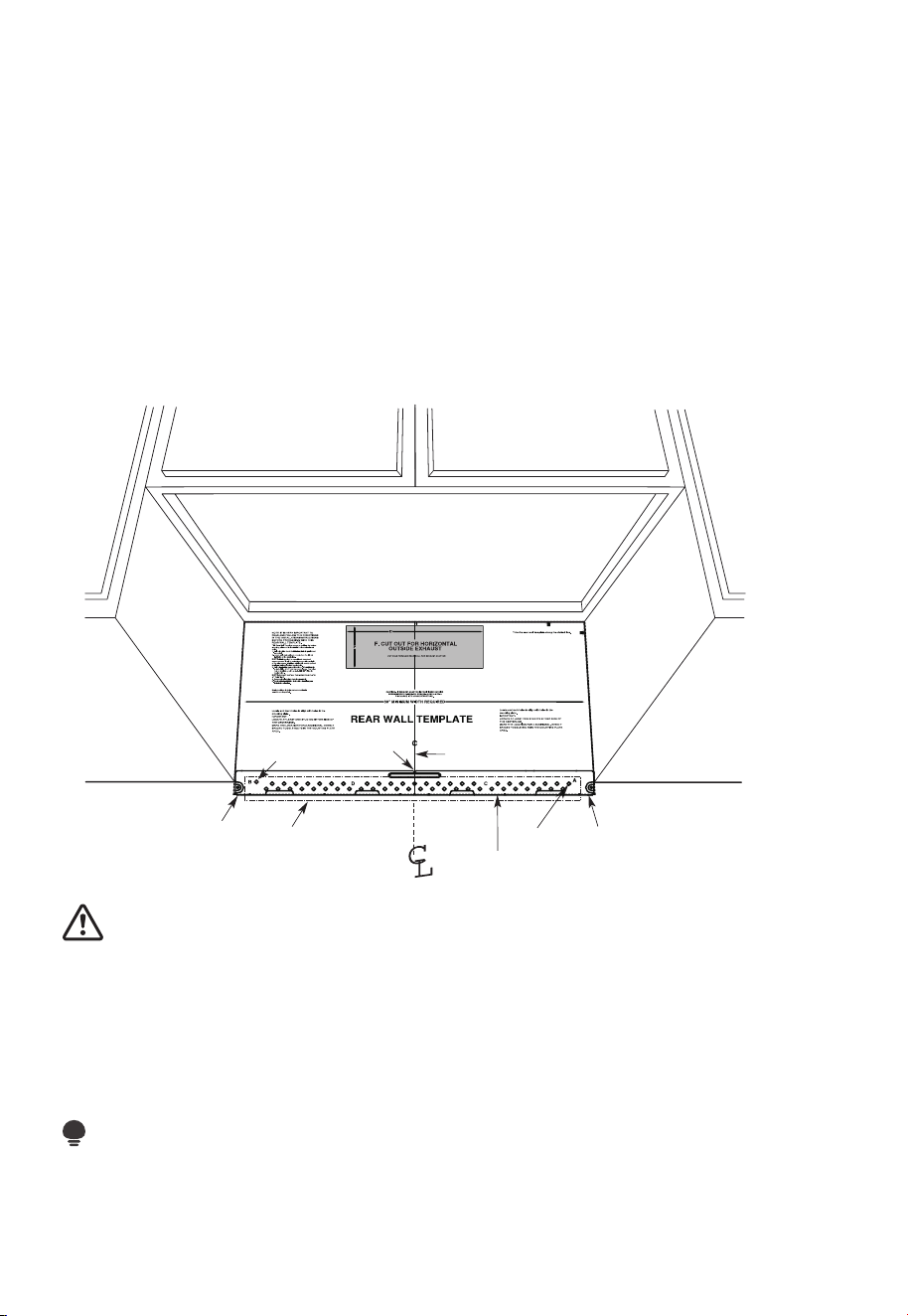
ES-22
Sus gabinetes pueden tener molduras decorativas que interfieren con la instalación del
microondas.
Retire la moldura decorativa para instalar correctamente el microondas y nivelarlo.
EL MICROONDAS DEBE ESTAR NIVELADO.
Utilice un nivel para asegurarse de que el fondo del gabinete está nivelado.
Si los gabinetes solo tienen un voladizo frontal, sin marco posterior ni lateral, instale
la placa de montaje a la misma distancia que la profundidad del voladizo frontal.
Estomantendrá el microondas nivelado.
1. Mida la profundidad interior del voladizo delantero.
2. Trace una línea horizontal en la pared trasera a la misma distancia por debajo del
fondo del gabinete que la profundidad interior del voladizo frontal.
3. Para este tipo de instalación sólo con voladizo frontal, alinee las pestañas de montaje
con esta línea horizontal, sin tocar el fondo del gabinete como se describe en el paso D.
D. ALINEACIÓN DE LA PLACA DE PARED
3/8" TO EDGE
Linea horizontal
Área E
Dibuje una línea horizontal en la pared en la parte
inferior de la “Plantilla de la pared posterior”.
Linea horizontalOrificio A
Orificio B
Muescas
en la línea
central
Dibuje una línea vertical en
la pared desde el centro
del armario superior
PRECAUCIÓN:
Utilice guantes para evitar cortarse los dedos con los bordes afilados.
1. Trace una línea vertical en la pared en el centro del espacio de 30" de ancho.
2. Trace una línea horizontal en la pared en la parte inferior de la "Plantilla de pared posterior".
3. Busque una viga de pared en el área "E" de la placa de montaje. Consulte la sección
1B. Encontrar las vigas de la pared.
4. Para fijar la placa de montaje en la viga, taladre un orificio de 3/16" en la viga de
madera. Perfore un orificio de 5/8" para el perno de palanca en otra ubicación
(OrificioA o B).
NOTA:
NO MONTE LA PLACA EN ESTE MOMENTO.
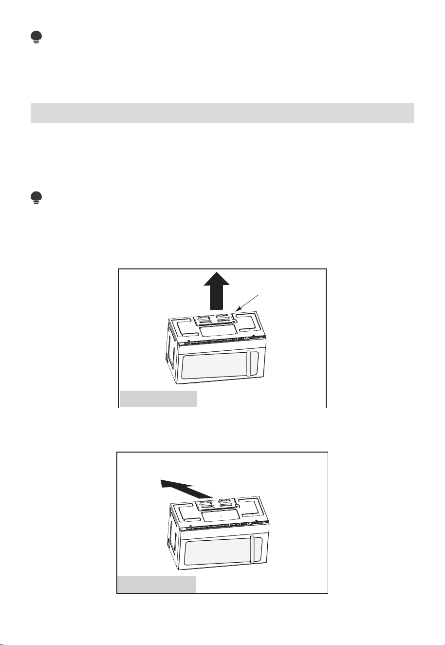
ES-23
NOTA:
Los orificios A y B están dentro del área E. Si ninguno de los orificios A y B están en una
viga, encuentre una viga en algún lugar del área E y dibuje un círculo para alinearlo con
la viga. Es importante tener al menos un tornillo para madera fijado firmemente en una
viga para soportar el peso del microondas. Coloque la placa de montaje a un lado.
2. Tipos de Instalación (Elija A, B o C)
Este horno de microondas está diseñado para adaptarse a los siguientes tres tipos de
ventilación:
A. Escape Superior Exterior (Conducto Vertical)
B. Escape Trasero Exterior (Conducto Horizontal)
C. Recirculación (Sin Conductos de Ventilación)
NOTA:
Este microondas se envía ensamblado para Recirculación. Seleccione el tipo de
ventilación necesario para su instalación y pase a esa sección.
A. ESCAPE SUPERIOR EXTERIOR (CONDUCTO VERTICAL)
Adaptador colocado
para la extracción
superior exterior
Ver página 26
B. ESCAPE TRASERO EXTERIOR (CONDUCTO HORIZONTAL)
Ver página 33
Adaptador movido hacia
atrás para la extracción
posterior exterior
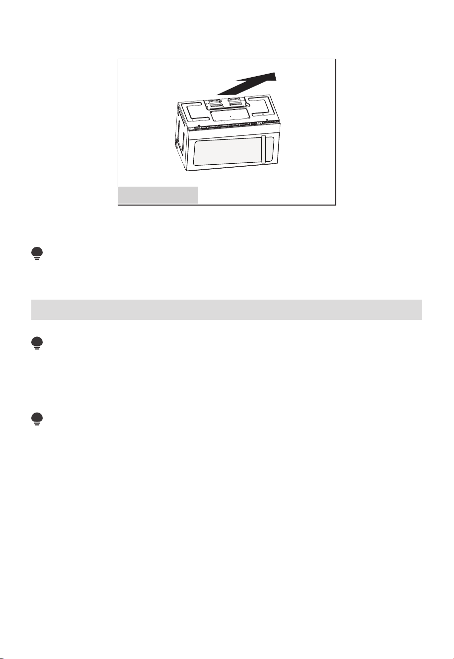
ES-24
C. RECIRCULACIÓN (SIN CONDUCTOS DE VENTILACIÓN)
Ver página 41
Los modelos se envían con escape para recirculación. Algunos modelos tienen instalado
un filtro de carbón desechable para ayudar a eliminar el humo y los olores.
NOTA:
Lea las dos páginas siguientes solo si tiene previsto realizar la ventilación de escape al
exterior. Si va a recircular el aire del ambiente en el lugar, vaya a la página 23-26.
Instrucciones de Instalación para Conductos de Escape Externos
NOTA:
Si necesita instalar conductos, tenga en cuenta que la longitud total del conducto
rectangular de 3
1
⁄
4
" x 10" (8.2 cm x 25.4 cm) o redondo de 5" (12.7 cm) / 6" (15.2 cm) de
diámetro, no debe superar los 120 pies equivalentes (36.5 m).
La ventilación exterior requiere un CONDUCTO DE ESCAPE EXTERNO. Lea atentamente
lo siguiente.
NOTA:
Es importante que la ventilación se instale usando la ruta más directa y con la menor
cantidad de codos posible. Esto asegura una ventilación despejada del escape y ayuda a
prevenir obstrucciones.
Asegúrese también de que las compuertas oscilan libremente y de que nada obstruye los
conductos.
Conexión del escape:
El adaptador de extracción ha sido diseñado para acoplarse a un conducto rectangular
estándar de 8.2 cm x 25.4 cm (3
1
⁄
4
" x 10").
Si se requiere un conducto redondo, se debe usar un adaptador de transición de
rectangular a redondo. Se puede utilizar un conducto de diámetro de A5" (12.7 cm) /
6"(15.2 cm).
Longitud máxima del conducto:
Para que el movimiento del aire sea satisfactorio, la longitud total del conducto
rectangular de 3
1
⁄
4
" x 10" (8.2 cm x 25.4 cm)
o redondo de 5"(12,7 cm) / 6" (15.2 cm) de diámetro, no debe
superar los 120 pies equivalentes (36.5 m).
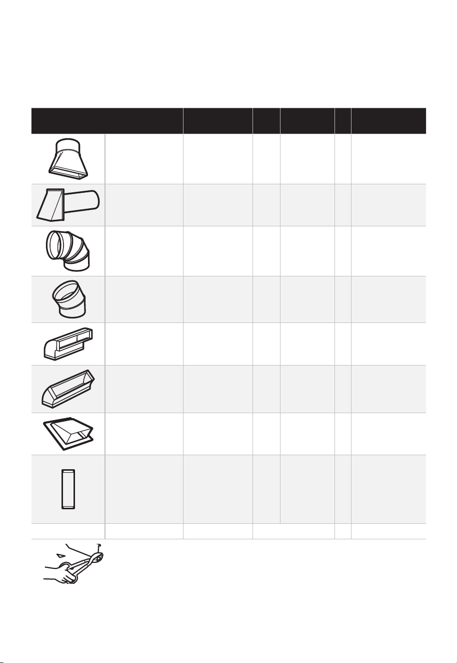
ES-25
Los codos, transiciones, tapas de paredes y techos, etc., presentan una resistencia
adicional al flujo de aire y equivalen a una sección de conducto recto más larga que
su tamaño físico real. Al calcular la longitud total del conducto, sume las longitudes
equivalentes de todas las transiciones y adaptadores más la longitud de todos los
tramos rectos del conducto. La siguiente tabla muestra cómo calcular la longitud total
equivalente de los conductos utilizando los pies aproximados de longitud equivalente de
algunos conductos típicos.
PIEZAS DEL CONDUCTO
LONGITUD
EQUIVALENTE
x
CANTIDAD
UTILIZADA
=
LONGITUD
EQUIVALENTE
Adaptador de
Transición de
Rectangular a
Redondo*.
5 pies (1.5 m) x ( ) = pies o m
Tapa de Pared 40 pies (12.2 m) x ( ) = pies o m
Codo de 90° 10 pies (3 m) x ( ) = pies o m
Codo de 45° 5 pies (1.5 m) x ( ) = pies o m
Codo de 90° 25 pies (7.6 m) x ( ) = pies o m
Codo de 45° 5 pies (1.5 m) x ( ) = pies o m
Tapa de Techo 24 pies (7.3 m) x ( ) = pies o m
Conducto Recto
Redondo de
6" (15.2 cm) o
Rectangular de
3
1
⁄
4
" x 10"
(8.2 x 25.4 cm)
1 pie (0.3 m) x ( ) = pies o m
Conductos Totales = pies o m
* IMPORTANTE: Si se utiliza un adaptador de transición de
rectangular a redondo, habrá que cortar las esquinas inferiores de
la compuerta para que encajen, utilizando tijeras para hojalata, con
el fin de permitir el libre movimiento de la compuerta.
Las longitudes equivalentes de los conductos se basan en pruebas reales y reflejan los
requisitos para un buen desempeño de la ventilación con cualquier campana de ventilación.
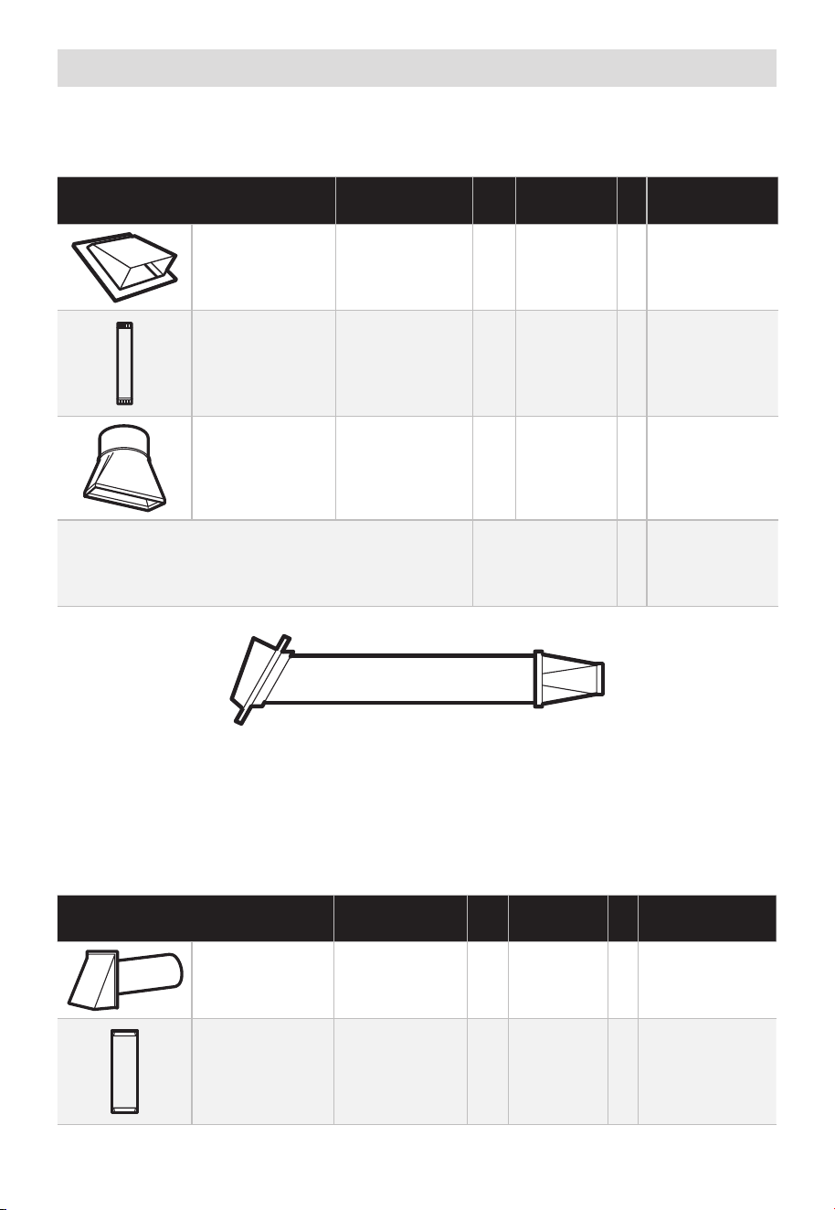
ES-26
Conductos de Escape Externos
ESCAPE SUPERIOR EXTERIOR (SOLO COMO EJEMPLO)
El siguiente cuadro describe un ejemplo de una posible instalación de conductos.
PIEZAS DEL CONDUCTO
LONGITUD
EQUIVALENTE
x
CANTIDAD
UTILIZADA
=
LONGITUD
EQUIVALENTE
Tapa de Techo 24 pies (7.3 m) x (1) = 24 pies (7.3 m)
Conducto
Recto de 12pies
(3.6m) y
Redondo
6"/15.2 cm
12 pie (3.6 m) x (1) = 12 pie (3.6 m)
Adaptador de
Transición de
Rectangular a
Redondo*.
5 pies (1.5 m) x (1) = 5 pies (1.5 m)
Las longitudes equivalentes de los conductos se
basan en pruebas reales y reflejan los requisitos
para un buen desempeño de la ventilación con
cualquier campana de ventilación.
Longitud Total = 41 pies (12.5 m)
* IMPORTANTE: Si se utiliza un adaptador de transición de rectangular a redondo, habrá
que cortar las esquinas inferiores de la compuerta para que encajen, utilizando tijeras
para hojalata, con el fin de permitir el libre movimiento de la compuerta.
ESCAPE TRASERO EXTERIOR (SOLO COMO EJEMPLO)
El siguiente cuadro describe un ejemplo de una posible instalación de conductos.
PIEZAS DEL CONDUCTO
LONGITUD
EQUIVALENTE
x
CANTIDAD
UTILIZADA
=
LONGITUD
EQUIVALENTE
Tapa de Pared 40 pies (12.2 m) x (1) = 40 pies (12.2 m)
Conducto Recto
de 3 pies y
Rectangular
(3
1
⁄
4
"x 10"/
8.2 x 25.4 cm)
3 pies (0.9 m) x (1) = 3 pies (0.9 m)
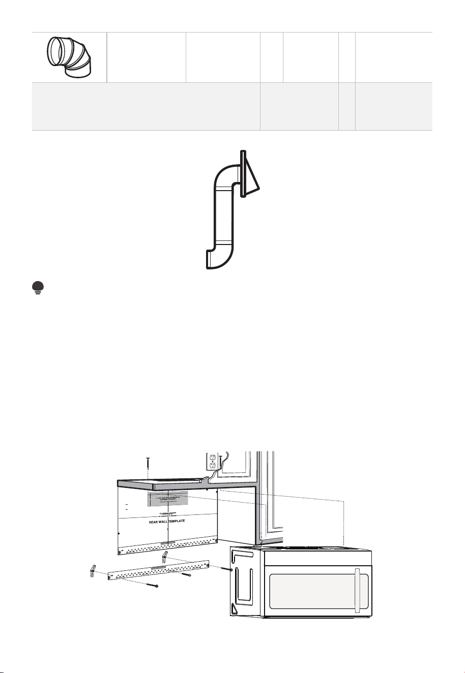
ES-27
Codo de 90° 10 pies (3 m) x (2) = 20 pies (3 m)
Las longitudes equivalentes de los conductos se
basan en pruebas reales y reflejan los requisitos
para un buen desempeño de la ventilación con
cualquier campana de ventilación.
Longitud Total = 63 pies (19.2 m)
NOTA:
Para el escape trasero, se debe tener cuidado de alinear el escape con el espacio entre
las vigas, o se debe preparar la pared en el momento de construirla dejando suficiente
espacio entre las vigas de la pared para acomodar el escape.
A. ESCAPE SUPERIOR EXTERIOR (Conducto Vertical)
REVISIÓN DE LA INSTALACIÓN
A1. Fije la placa de montaje a la pared
A2. Preparar el gabinete superior
A3. Configurar el ventilador del microondas para escape exterior/superior
A4. Comprobar el funcionamiento de la compuerta
A5. Montar el horno microondas
A6. Ajustar el adaptador del escape
A7. Conectar los conductos
12"
4"
NOTE:
READ AND F
O
I
T
I
S
V
ERY
LLO
I
W
MPO
T
HE
R
D
TANT T
O
IRECTIO
IN THE INSTALLATI
ON
INSTRU
CTIO
N
N
S
S
BE
F
O
RE
PRO
H
T
H
TI W G N I D E E
C
IS
REAR
W
ALL
TEM
PL
A
TE
.
ll Templ
a
te s
erv
es t
o
p
1
ou
a
. Us
mo
u
tl
e
t.
ntin
e
a l
T
hi
s
Rea
g
p
rW
l
a
a
t
e
a
nd
to
lo
ca
te
th
e
h
ori
z
o
s
o
n
itio
ta
n
l e
t
h
xh
e b
au
o
st
t
t
o
m
ionedto check
tha
t
th
e
t
e
mplate
s
o
p si
it
pl
ar
k hol
es
to a
li
gn with holes
in the
L
oca
t
mounting
RTANT
e and m
:
ate
.
IMPO
E
AT LEA
THE CENT
HE LO
CATIO
L
OC
AT
E
RL
INE
ST
.
O
NE STUD ON EI F O
E D I SRE H
T
SP
AC
E
AREA.
MAR
K
T
D TO
GGLE
BO
NF
LT
S
O
IN
R 2 ADD
IT
THE MO
IO
UN
NA
TING
L, EVENL
PLA
TE
Y
Trim the r
e
ar wal
l template a
long
the
dott
ed
l
ine.
k
h
ole
s to
a
l
i g
n with h
ole
s
in t
he
m
ounting
L
oca
te a
n
d
mar
O
RT
AN
T
plate.
:IMP
AT LEA
THE
CENT
HE
L
OCATIO
SP
LOCATE
ER
L
I
NE.
I E N
O
D
U T
S E
N O
TS THER SI
D
E OF
AR
EA.
MARK
ACED
T
T
OG
G
LE B
O
N
FO
LTS IN
R 2
ADDITION
THE
MO
UN
A
T
ING
L,
EV
ENL
PLATE
Y
Trim the rear
w
a
l
l te
m
plate along
t
he do
tt
ed
lin
e.
3/8"
TOEDGE
2. L
o
c
c
cu
a
te
r
a
e
a
tely
v
nd
el
.
m
a
r
k a
t leas
t
o
d
u
ts
e
n
o
n
th r
o
t
f
e
l
e
igh
t
si
d
e of
t
he cente
rl
eni
.
r
It is im
p
o
rta
nt to
u
s
e
at l
e
ts
a one
wood
sc
rew
mo
ro
unte
d
wa
v
fi
e.
r
M
ml
y
ar
i
k
n
t
a
w
s
o
a
tud
d
di
t
i
to
s
up
p
ona
l,
ev
or
en
t
the
w
ly
s
e
pa
ight
ced
e mic
f
e
o
r
s
i
n
t
he
th
s
e
u
m
ppl
ar
k
ied to
ed
l
o
g
c
g
le bo
l
ation
t
s
s
.
.
Wh
ere t
her
e is
lo
o
f
a
c
th
3. Dr
a
th
s
i
tio
at
ll
tu
n
h
d
s
ol
d
ri
l
l a
3/1
6"
h
ole for
w
oo
d
sc
r
e
w
s
.
F
o
r
h
o
l
es
do
,
h t i
w
p
u
e
a
stud, dri
l
l
5/8
" h
oles
fo
r
e bo
n
o
lts
t
li
n
.
NO
T
t
oggl
IN
STAL
L
T
HE
MO
U
N
TI
NG
P
L
ATE
AT
4.
R
e
T
m
HI
S
T
D
O
th
IME.
e te
o
v
e
mp
l
a
te fr
omth
e r
ea
r
wall
.
5.Re
v
ie
w
the I
n
stall
a
t s n I n
o i
t ruc
t
i
on bo
o
k for you
r
instal
l
a
t
io
n s
it
ua
tio
n
.
Dar
le
vu
el
t
a
ala
hojapa
raco
ns
ul
t
ar
la
v
e
r
si
ón
en
Espa
ño
l.
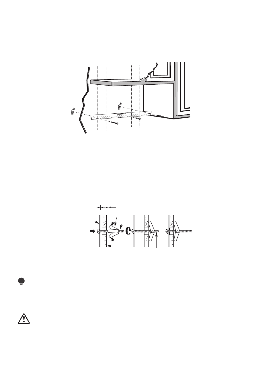
ES-28
NOTAS IMPORTANTES:
1. Asegúrese de que los tornillos del motor del ventilador y la placa del ventilador estén
bien apretados cuando estén instalados. Esto ayudará a evitar vibraciones excesivas.
2. Asegúrese de que el cableado del motor se haya instalado y asegurado correctamente,
y que los cables no estén aplastados.
A1. FIJACIÓN DE LA PLACA DE MONTAJE A LA PARED
• Fije la placa a la pared utilizando pernos de anclaje.
• Se debe utilizar al menos un tornillo para madera para fijar la placa a un montante de
pared.
1. Retire las alas de anclaje de los pernos
2. Inserte los pernos en la placa de montaje a través de los orificios designados para la
pared de yeso y vuelva a colocar las alas de anclaje a 3/4" (19 mm) en cada perno.
Para utilizar pernos de anclaje:
Espaciado para alternar más
que el grosor de la pared
Alas de perno de anclaje
Perno de
anclaje
Extremo del perno
Pared
Placa de
montaje
3. Coloque la placa de montaje contra la pared e inserte las alas de anclaje en los
orificios de la pared para montar la placa.
NOTA:
Antes de apretar los pernos de anclaje y el tornillo para madera, asegúrese de que la
parte inferior de la placa de montaje toque la parte inferior del armario cuando se empuje
al ras contra la pared y que la placa esté correctamente centrada debajo del armario.
PRECAUCIÓN:
Tenga cuidado y evite pillarse los dedos entre la parte posterior de la placa de montaje y
la pared.
4. Apriete todos los tornillos. Retire la placa de la pared para ayudar a apretar los pernos.
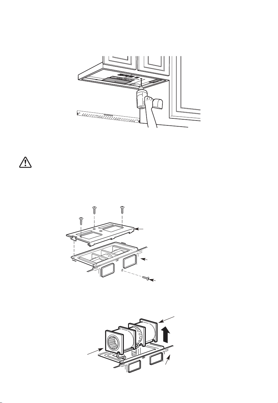
ES-29
A2. UTILICE LA PLANTILLA DEL ARMARIO SUPERIOR PARA LA
PREPARACIÓN DEL ARMARIO SUPERIOR
Taladre los orificios para los tornillos de soporte superiores, un orificio lo suficientemente
grande para que pase el cable de alimentación y un corte lo suficientemente grande para
el adaptador de extracción.
1. Lea las instrucciones de la PLANTILLA DEL ARMARIO SUPERIOR.
2. Péguelo debajo del armario superior.
3. Taladre los orificios siguiendo las instrucciones de la PLANTILLA DEL ARMARIO
SUPERIOR.
PRECAUCIÓN:
Utilice lentes de seguridad cuando taladre orificios en la parte inferior del armario.
A3. ADAPTACIÓN DEL VENTILADOR DE MICROONDAS PARA LA
EXTRACCIÓN SUPERIOR EXTERNA
1. Coloque el microondas en posición vertical, con la parte superior de la unidad hacia arriba.
Placa del ventilador
Parte posterior del
microondas
Tornillo del motor del ventilador
Retire el tornillo que sujeta la placa del ventilador al microondas. Retire y guarde el
tornillo que sujeta el motor del ventilador al microondas.
2. Extraiga con cuidado la unidad del ventilador. Los cables se extenderán lo suficiente
para permitirle ajustar la unidad del ventilador.
Extremo B
Parte posterior
del microondas
Extremo A
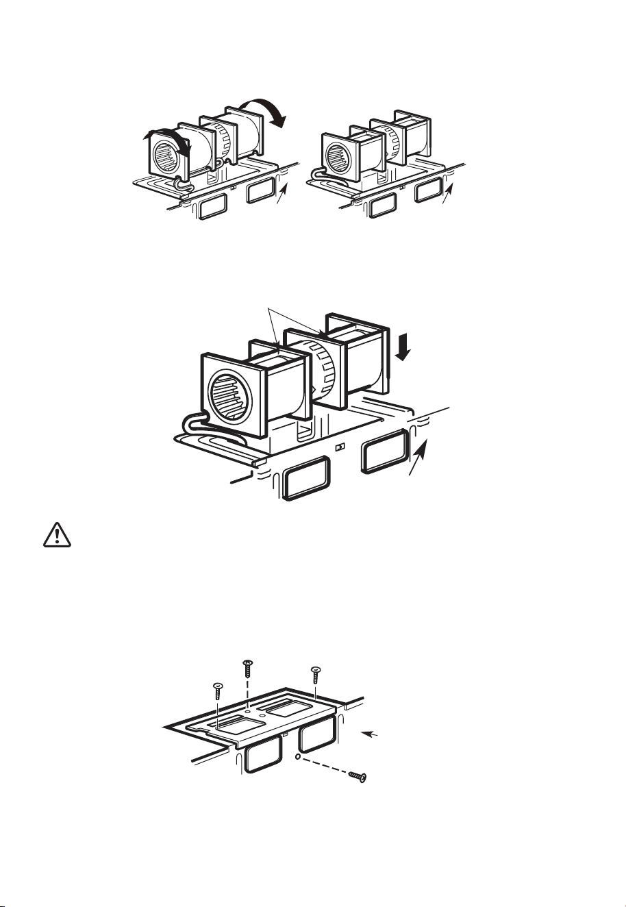
ES-30
3. Gire la unidad del ventilador 90° para que las aberturas de las aspas del ventilador
queden hacia afuera de la parte superior del microondas.
Antes de la rotación Después de la rotación
Parte posterior
del microondas
Parte posterior
del microondas
4. Vuelva a colocar la unidad del ventilador en la abertura.
DESPUÉS: Aberturas de las aspas del
ventilador orientadas hacia arriba
Parte posterior
del microondas
PRECAUCIÓN:
No tire ni estire el cableado de la unidad del ventilador. Asegúrese de que los cables no
estén aplastados y que estén correctamente asegurados.
5. Asegure la unidad del ventilador al microondas con el tornillo retirado en el Paso 1.
Asegúrese de que el tornillo esté apretado.
6. Vuelva a colocar la placa del ventilador con el tornillo retirado en el Paso 1. Asegúrese
de que el tornillo esté apretado.
Parte posterior
del microondas
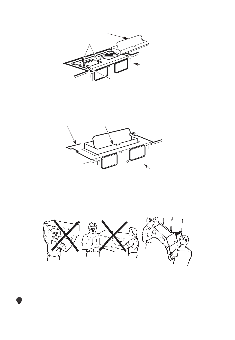
ES-31
7. Fije el adaptador de extracción a la parte superior de la placa del ventilador
deslizándolo en las guías de la placa del ventilador.
Adaptador
Guía
Parte posterior
del microondas
Pestañas de bloqueo
Presione firmemente hasta que quede en las lengüetas de bloqueo. Asegúrese de que la
bisagra del amortiguador esté instalada de forma que el amortiguador oscile libremente.
A4. COMPOBACIÓN DEL CORRECTO FUNCIONAMIENTO DEL
AMORTIGUADOR
Parte posterior
del microondas
Amortiguador
Adaptador de
extracción
Placa del
ventilador
• Antes de montar el microondas, asegúrese de que se haya retirado la cinta adhesiva
que sujeta el amortiguador y de que ésta gire con facilidad.
• Tendrá que hacer ajustes para asegurar una alineación adecuada con el conducto de
extracción de su casa después de instalar el microondas.
A5. MONTAJE DEL HORNO MICROONDAS
PARA UNA FÁCIL INSTALACIÓN Y SEGURIDAD PERSONAL, RECOMENDAMOS QUE
DOS PERSONAS INSTALEN ESTE HORNO MICROONDAS.
IMPORTANTE: No sujete ni utilice el mango o el protector térmico durante la instalación.
No retire los separadores de cartón entre el protector térmico y la puerta.
NOTA:
Si su armario es de metal, utilice la arandela de nailon alrededor del orificio del cable de
alimentación para evitar que se corte el cable.
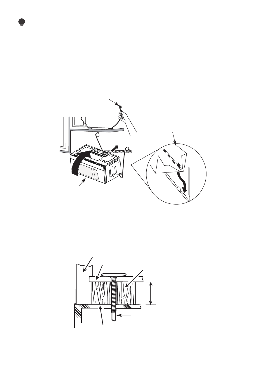
ES-32
NOTA:
Se recomienda utilizar bloques de relleno si la parte delantera del armario cuelga por
debajo del estante inferior del armario.
IMPORTANTE: Si no se utilizan los bloques de relleno, se pueden producir daños en la
carcasa debido a un apriete excesivo de los tornillos.
NOTA: Al montar el horno
microondas, pase el cable de
alimentación a través del orificio
en la parte inferior del armario
superior. Manténgalo apretado
durante los pasos 1-3. No aplaste
el cable ni levante el horno
tirando del cable.
1. Levante el microondas,
inclínelo hacia adelante y
enganche las ranuras en el
borde inferior posterior en las
cuatro lengüetas inferiores de
la placa de montaje.
2 Gire el frente del horno
contra el fondo del armario.
3. Inserte un tornillo de autoalineación a través del orificio central superior del armario.
Asegure temporalmente el horno girando el tornillo al menos dos vueltas completas
después de que las roscas hayan encajado. (Se apretará completamente más tarde).
Asegúrese de mantener apretado el cable de alimentación. Tenga cuidado de no
aplastar el cable, especialmente cuando lo monte al ras de la parte inferior del armario.
Frente del armario
Estante inferior del armario
Bloque de relleno
Equivalente a la
profundidad del
orificio del armario
Tornillo de autoalineación
Parte superior del horno microondas
4. Fije el horno microondas al armario superior.
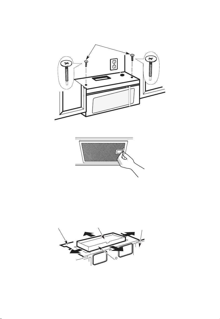
ES-33
5. Inserte 2 tornillos de
autoalineación a través de los
orificios exteriores del armario
superior. Gire dos vueltas
completas cada tornillo.
6. Apriete los dos tornillos exteriores a la parte superior del horno microondas. (Mientras
aprieta los tornillos, sujete el horno microondas contra la pared y el armario superior).
7. Instale los filtros de grasa. Consulte la Guía de uso y cuidado incluida con el
microondas.
A6. AJUSTE DEL ADAPTADOR DE EXTRACCIÓN
Abra el armario superior y ajuste el adaptador de extracción para conectarlo al conducto
de la casa.
Placa del
ventilador
Amortiguador
Parte posterior
del microondas
Para el ajuste de adelante hacia
atrás o de lado a lado, deslice
el adaptador de extracción
según sea necesario.
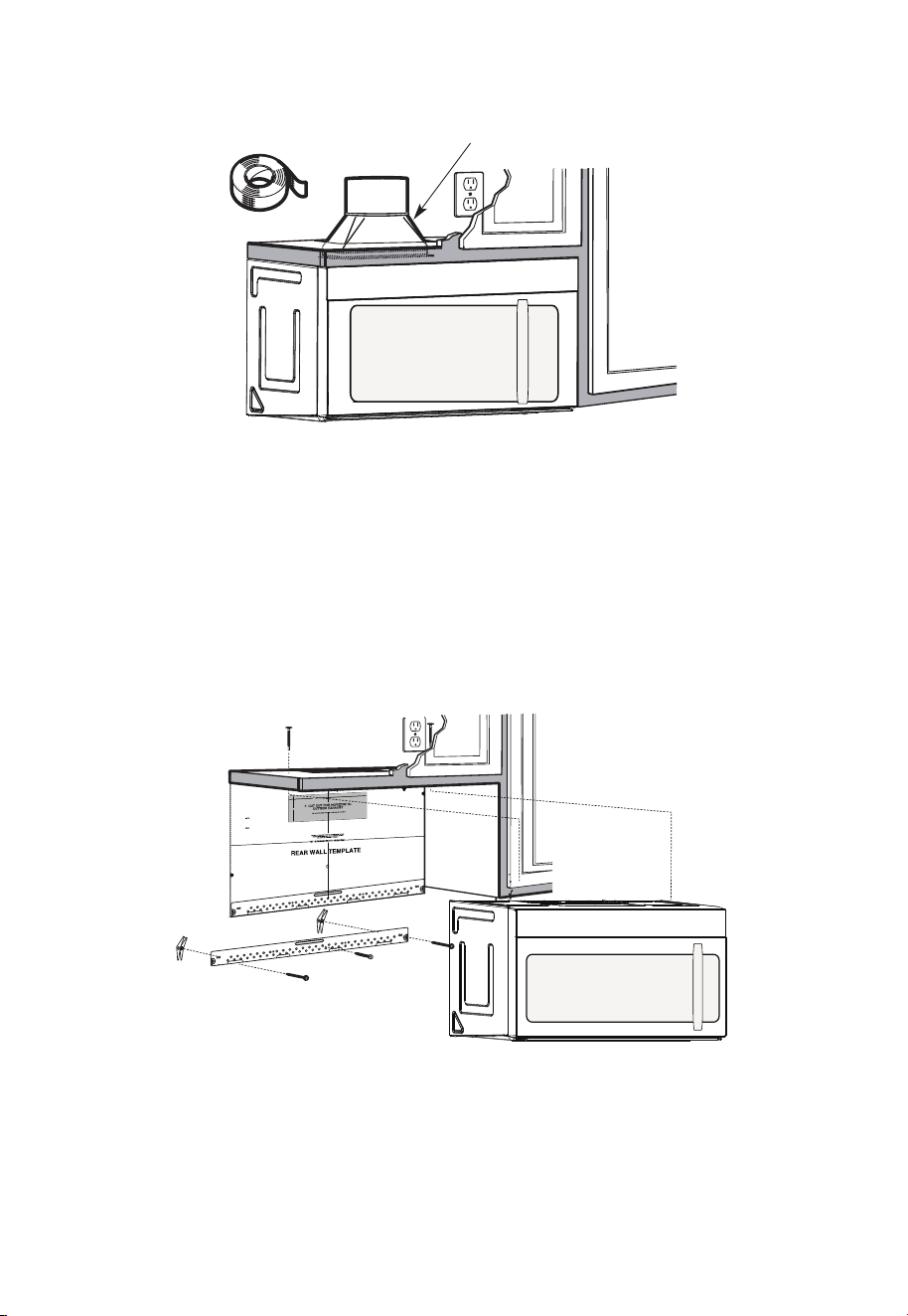
ES-34
A7. CONEXIÓN DEL CONDUCTO
Conducto de la casa
1. Extienda el conducto de la casa hacia abajo para conectarlo al adaptador de extracción.
2. Selle las juntas del conducto de extracción con cinta adhesiva para conductos de alta
temperatura
B. ESCAPE TRASERO EXTERIOR (conducto horizontal)
REVISIÓN DE LA INSTALACIÓN
B1. Prepare la pared posterior
B2. retiro de la placa del ventilador
B3. Fije la placa de montaje a la pared
B4. Preparar el gabinete superior
B5. Ajuste el ventilador
B6. montaje del horno microondas
12"
4"
NOTE
:
REA
D AND FO
I
T
I
S
V
ERY
LLO
I
W
MPO
T
HE
R
D
TANT
T
O
IRECTIO
IN THE INSTALLAT
I
ON I
NSTRU
CTI
O
N
N
S
S
B
EF
O
RE PR
O
H
T
H T I
W
G N
I
D E
E
C IS
REAR WA
L
L TEM
PL
ATE
.
ll Te
mpl
a
te
serv
es
to p
1
ou
a
. Us
mou
tle
t.
ntin
e
a l
T
h
is
R
ea
g
p
rW
l
a
a
t
e
and
to
loca
te
th
e h
or
iz
o
s
o
n
itio
t
a
n
l e
t
h
xh
e b
au
o
st
t
t
o
m
ioned
to
chec
k tha
t
th
e
t
e
m
pl
at
e
is
p
osit
pl
ark
holes
to
ali
gn wi
th holes
i
n t
he
L
ocat
mounting
RTANT
e and m
:
ate
.
IMPO
E
AT LEA
THE CENT
HE LOCATIO
L
O
C
AT
ERL
INE
ST
.
ONE STUD
ON EI
F
O
ED I S R
E H
T
SP
AC
E
AREA.
MAR
KT
D T
OGGLE
BO
NF
LT
S
O
I
N
R 2 ADD
IT
THE MO
IO
UN
NA
T
ING
L, EV
EN
L
P
LATE
Y
Trim the
re
ar wal
l tem
plat
e along
the
dott
e
d l
ine.
k
h
ole
s to g
ila n w
ith holes
in t
he
moun
tin
g
Loca
te a
n
d
mar
O
RTAN
T
plate.
:IMP
AT LEA
THE CENT
HE
L
O
CATIO
SP
LOCA
T
E
ERLI
N
E.
I
E
N O
D
U
T S E
N O T
S
T
HE
R S
I
D
E
OF
ARE
A.
MA
RK
ACED
T
T
OGG
LE BO
N
F
O
LTS IN
R 2 ADD
ITION
T
H
E
M
OUN
A
TING
L,
EVENL
PLATE
Y
Trim the rear
w
al
l t
e
m
plat
e
a
longt
he dotted
li
ne.
3/8"
TOEDGE
2. L
o
c
c
c
u
a
te
r
a
e
a
t
e
ly
v
nd
el
.
m
a
r
k a
t leas
t
o
d
u
ts
e
n
o
n
th r
o t
f
e l
e
i
ght
si
de of th
e c
ent
e
r
en
il
.
r
It is importa
nt to
use at
l
eas t o
ne
wo
od
sc
rew
mo
ro
unte
d
wa
v
fi
e.
r
M
ml
y
ar
i
k
n
t
a
w
s
o
a
t
ud
d
diti
to sup
p
ona
l, ev
or
en
t the w
ly
s
e
pa
ight
ced
e mic
f
e
o
r
s
i
n
t
he
t
h
s
e
u
m
p
pl
ark
ied to
ed l
o
g
c
g
le bo
l
ati
on
t
s
s
.
.
Wher
e th
er
e is
lo
o
f
a
c
th
3. Dr
a
th
s
i
tio
at
ll
tu
n
h
d
s
ol
d
ri
l
l
a
3/1
6" hol
e fo
r w
ood sc
r
e
ws. F
o
r
h
ol
es
do
,
h t
i
w
p
u
e
a
st
u
d, dril
l
5/8" h
ol
es
fo
r
e bo
no
lts
t lin
.
NO
T
t
oggl
IN
STAL
L
T
H
E
MO
U
NTI
NG
PLATE
AT
4.
R
e
T
m
HI
S
T
D
O
th
IME.
e te
o
v
e
mpla
te fr
omthe rea
r
wall
.
5.R
e
v
ie
w
the In
s
ta
ll
a
t s n I n
o
i
t r
uc
t
ion bo
o
k for your
ins
ta
lla
t
io
n sit
ua
tio
n
.
Darle
vu
el
t
a
ala
ho
japa
raco
ns
ul
tar
la
v
e
rs
i
ón
en
Espa
ño
l.
NOTAS IMPORTANTES:
1. Asegúrese de que los tornillos para el motor del ventilador y la placa del ventilador
estén bien apretados cuando se vuelvan a instalar. Esto ayudará a evitar vibraciones
excesivas.
2. Asegúrese de que el cableado del motor se haya instalado y asegurado correctamente,
y que los cables no estén aplastados.
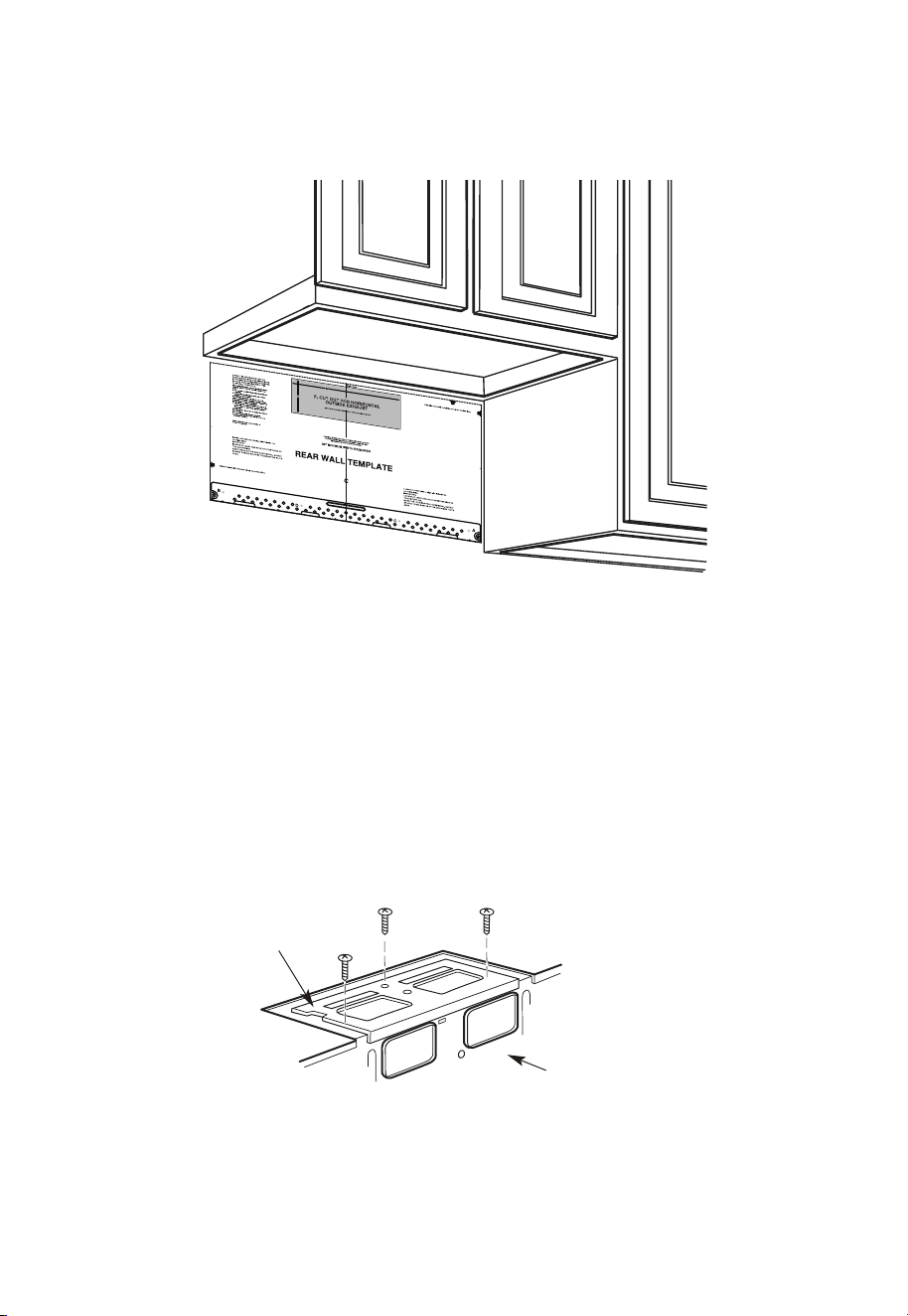
ES-35
B1. PREPARACIÓN DE LA PARED POSTERIOR PARA LA EXTRACCIÓN
POSTERIOR EXTERIOR
Es necesario cortar una abertura en la pared posterior para la extracción exterior.
1. Lea las instrucciones de la PLANTILLA DE PARED POSTERIOR. Péguela a la pared
posterior.
2. Corte la abertura, siguiendo las instrucciones de la
3. PLANTILLA DE PARED POSTERIOR.
B2. RETIRO DE LA PLACA DEL VENTILADOR
Retire y guarde el tornillo que sujeta la placa del ventilador al microondas. Levante la
placa del ventilador.
Placa del
ventilador
Parte posterior
del microondas
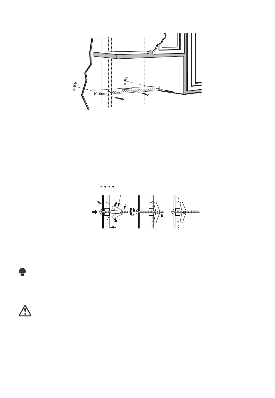
ES-36
B3. FIJACIÓN DE LA PLACA DE MONTAJE A LA PARED
Fije la placa a la pared utilizando pernos de anclaje. Se debe utilizar al menos un tornillo
para madera para fijar la placa a un montante de pared.
1. Retire las alas de anclaje de los pernos.
2. Inserte los pernos en la placa de montaje a través de los orificios designados para la
pared de yeso y vuelva a colocar las alas de anclaje a 3⁄ 4" (19 mm) en cada perno.
Para utilizar pernos de anclaje:
Espaciado para
alternar más que el
grosor de la pared
Alas de perno de anclaje
Perno de
anclaje
Pared
Placa de
montaje
Extremo del perno
3. Coloque la placa de montaje contra la pared e inserte las alas de anclaje en los
orificios de la pared para montar la placa.
NOTA:
Antes de apretar los pernos de anclaje y el tornillo para madera, asegúrese de que la
parte inferior de la placa de montaje toque la parte inferior del armario cuando se empuje
al ras contra la pared y que la placa esté correctamente centrada debajo del armario.
PRECAUCIÓN:
Tenga cuidado de no pillarse los dedos entre la parte posterior de la placa de montaje y
la pared.
4. Apriete todos los tornillos. Retire la placa de la pared para ayudar a apretar los pernos.
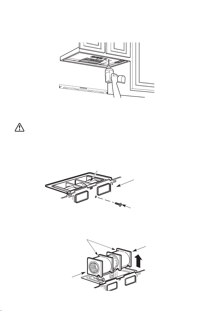
ES-37
B4. UTILICE LA PLANTILLA DEL ARMARIO SUPERIOR PARA LA
PREPARACIÓN DEL ARMARIO SUPERIOR
Es necesario taladrar orificios para los tornillos del soporte superior y un orificio lo
suficientemente grande para que pase el cable de alimentación.
1. Lea las instrucciones de la PLANTILLA DEL ARMARIO SUPERIOR.
2. Péguelo debajo del armario superior.
3. Taladre los orificios siguiendo las instrucciones de la PLANTILLA DEL ARMARIO SUPERIOR.
PRECAUCIÓN:
Utilice lentes de seguridad cuando taladre orificios en la parte inferior del armario.
B5. ADAPTACIÓN DEL VENTILADOR DE MICROONDAS PARA LA
EXTRACCIÓN POSTERIOR EXTERNA
1. Retire y guarde el tornillo que sujeta el motor del ventilador al microondas.
Motor del ventilador
Parte posterior
del microondas
Tornillo del motor
del ventilador
2. Extraiga con cuidado la unidad del ventilador. Los cables se extenderán lo suficiente
para permitirle ajustar la unidad del ventilador.
Antes: Aberturas de las aspas del
ventilador orientadas hacia adelante
Extremo B
Extremo A
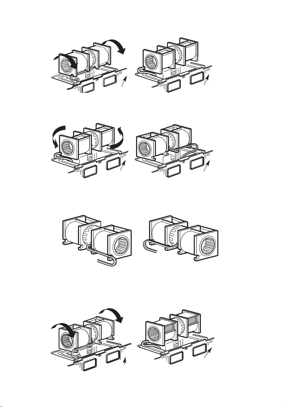
ES-38
3. Gire la unidad del ventilador 90°.
Antes de la rotación
Parte posterior
del microondas
Parte posterior
del microondas
Después de la rotación
4. Gire la unidad del ventilador 180° en sentido antihorario.
Antes de la rotación
Después de la rotación
Parte posterior
del microondas
Parte posterior
del microondas
5. Retire con cuidado los cables de las ranuras. Vuelva a pasar los cables por las ranuras
del otro lado de la unidad del ventilador.
Antes de la rotación
Cables colocados a
través del lado derecho
Cables colocados a
través del lado izquierdo
Después de la rotación
6. Gire la unidad del ventilador 90° de modo que las aberturas de las aspas del ventilador
queden orientadas hacia la parte posterior del microondas.
Antes de la rotación
Después de la rotación
Parte posterior
del microondas
Parte posterior
del microondas
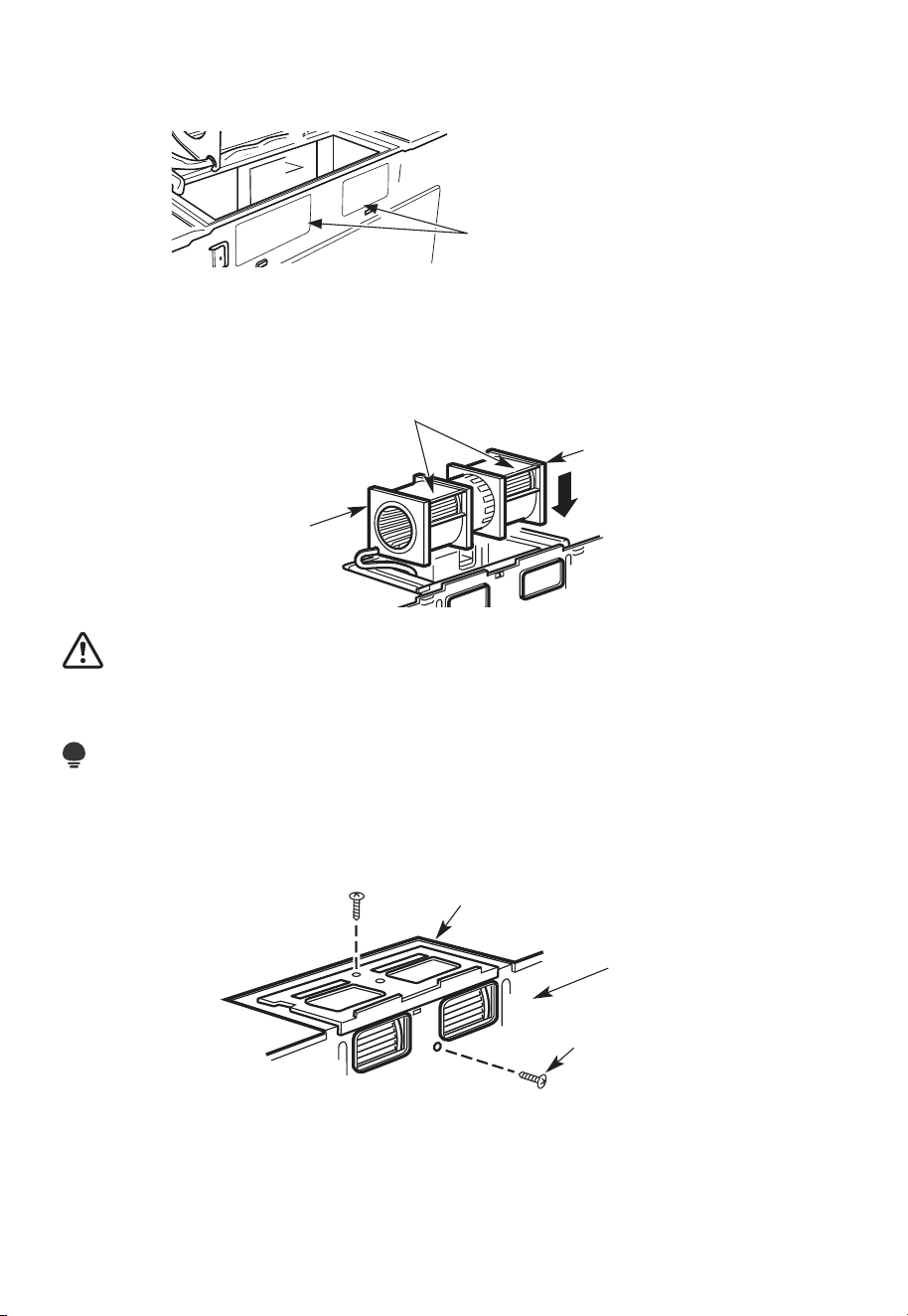
ES-39
7. Retire las placas ciegas de la parte posterior de la unidad con unas tijeras. (paraalgunos
modelos)
Placas ciegas: Corte las 4 bandas
de cada panel ciego y retire los
orificios ciegos de metal para
el flujo de aire posterior. Tenga
cuidado al retirar los bordes
afilados creados al retirar las
placas ciegas.
Parte posterior del microondas
8. Vuelva a colocar la unidad del ventilador en la abertura.
DESPUÉS: Aberturas de las aspas del
ventilador orientadas hacia atrás
Extremo A
Extremo B
PRECAUCIÓN:
No tire ni estire el cableado de la unidad del ventilador. Asegúrese de que los cables no
estén aplastados y que estén correctamente asegurados.
NOTA:
Las aberturas de extracción de la unidad del ventilador deben coincidir con las aberturas
de extracción de la parte posterior del horno microondas.
9. Asegure la unidad del ventilador al microondas con el tornillo original.
Placa del ventilador
Parte posterior
del microondas
Tornillo del motor
del ventilador
10. Vuelva a colocar la placa del ventilador en la misma posición que antes con el tornillo.
Asegúrese de que el tornillo esté apretado.
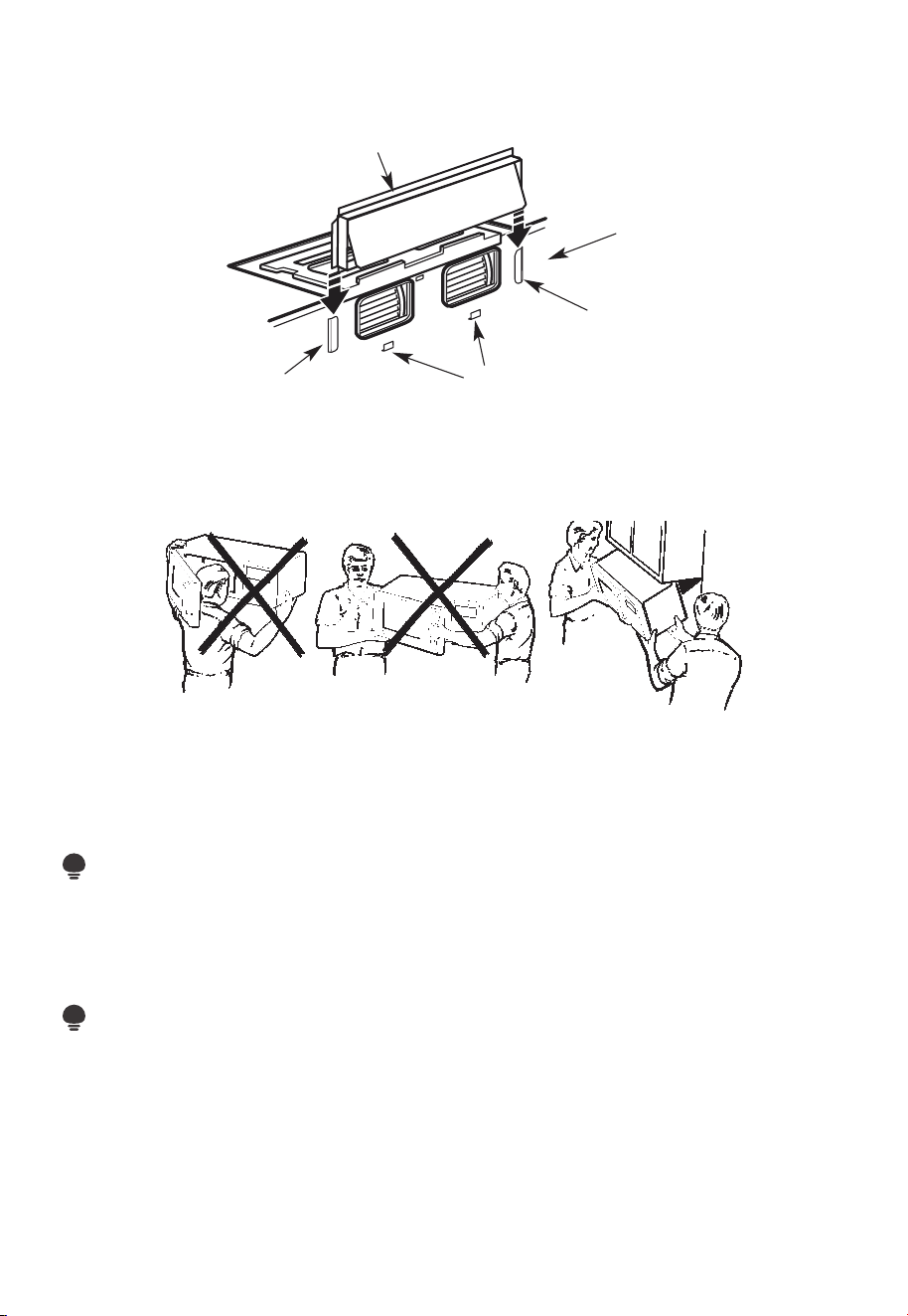
ES-40
11. Fije el adaptador de extracción a la parte posterior del horno deslizándolo en las guías
de la parte superior central de la parte posterior del horno.
Adaptador
Parte posterior
del microondas
Guía
Pestañas de bloqueo
Guía
Empújelo firmemente hasta que quede en las lengüetas de bloqueo inferiores.
Asegúresede que la bisagra del amortiguador esté instalada de modo que quede en la
parte superior y que el amortiguador oscile libremente.
B6. MONTAJE DEL HORNO MICROONDAS
PARA UNA FÁCIL INSTALACIÓN Y SEGURIDAD PERSONAL, RECOMENDAMOS QUE
DOS PERSONAS INSTALEN ESTE HORNO MICROONDAS.
IMPORTANTE: No sujete ni utilice el mango o el protector térmico durante la instalación.
No retire los separadores de cartón entre el protector térmico y la puerta.
NOTA:
Si su armario es de metal, utilice la arandela de nailon alrededor del orificio del cable de
alimentación para evitar que se corte el cable.
NOTA:
Se recomienda utilizar bloques de relleno si la parte delantera del armario cuelga por
debajo del estante inferior del armario.
IMPORTANTE: Si no se utilizan los bloques de relleno, se pueden producir daños en la
carcasa debido a un apriete excesivo de los tornillos.
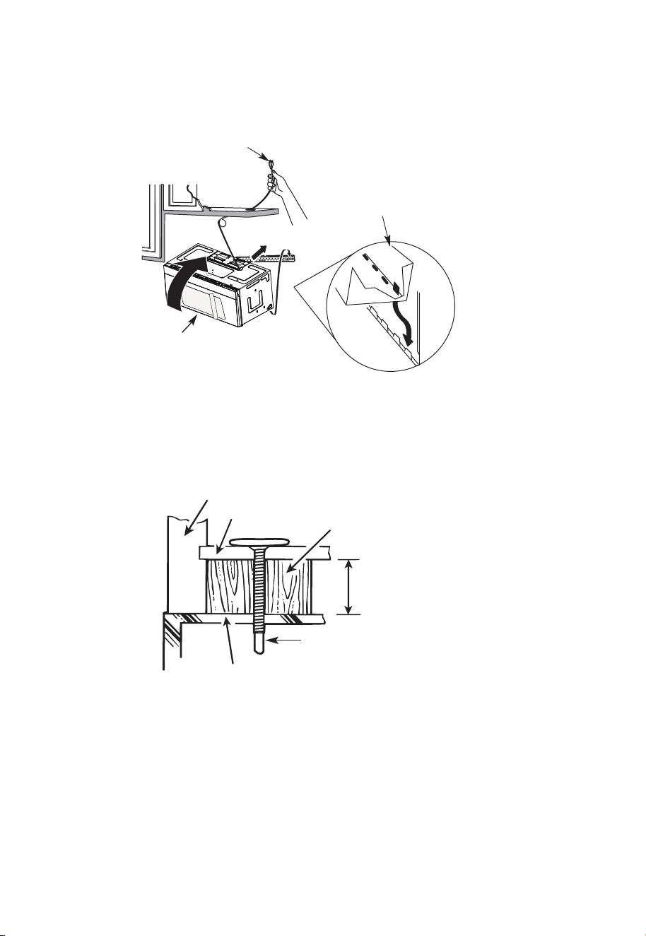
ES-41
NOTA: Al montar el horno
microondas, pase el cable de
alimentación a través del orificio
en la parte inferior del armario
superior. Manténgalo apretado
durante los pasos 1-3. No aplaste
el cable ni levante el horno
tirando del cable.
1. Levante el microondas,
inclínelo hacia adelante y
enganche las ranuras en
el borde inferior posterior
en las cuatro lengüetas
inferiores de la placa de
montaje.
2. Gire el frente del horno
contra el fondo del armario.
3. Inserte un tornillo de autoalineación a través del orificio central superior del armario.
Asegure temporalmente el horno girando el tornillo al menos dos vueltas completas
después de que las roscas hayan encajado (se apretará completamente más tarde).
Asegúrese de mantener apretado el cable de alimentación. Tenga cuidado de no
aplastar el cable, especialmente cuando lo monte al ras de la parte inferior del armario.
Frente del armario
Estante inferior del armario
Bloque de relleno
Equivalente a la
profundidad del
orificio del armario
Tornillo de autoalineación
Parte superior del horno microondas
4. Fije el horno microondas al armario superior.
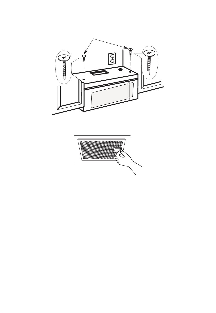
ES-42
5. Inserte 2 tornillos de autoalineación
a través de los orificios exteriores del
armario superior. Gire dos vueltas
completas cada tornillo.
6. Apriete los dos tornillos exteriores a la parte superior del horno microondas. (Mientras
aprieta los tornillos, sujete el horno microondas contra la pared y el armario superior).
7. Instale los filtros de grasa. Consulte la Guía de uso y cuidado incluida con el microondas
para obtener más información.
C. RECIRCULACIÓN (sin conductos de ventilación)
REVISIÓN DE LA INSTALACIÓN
C1. Fije la placa de montaje a la pared
C2. Preparar el gabinete superior
C3. comprobación de la placa del ventilador
C4. montaje del horno microondas
C5. Instale o cambie el filtro de carbón
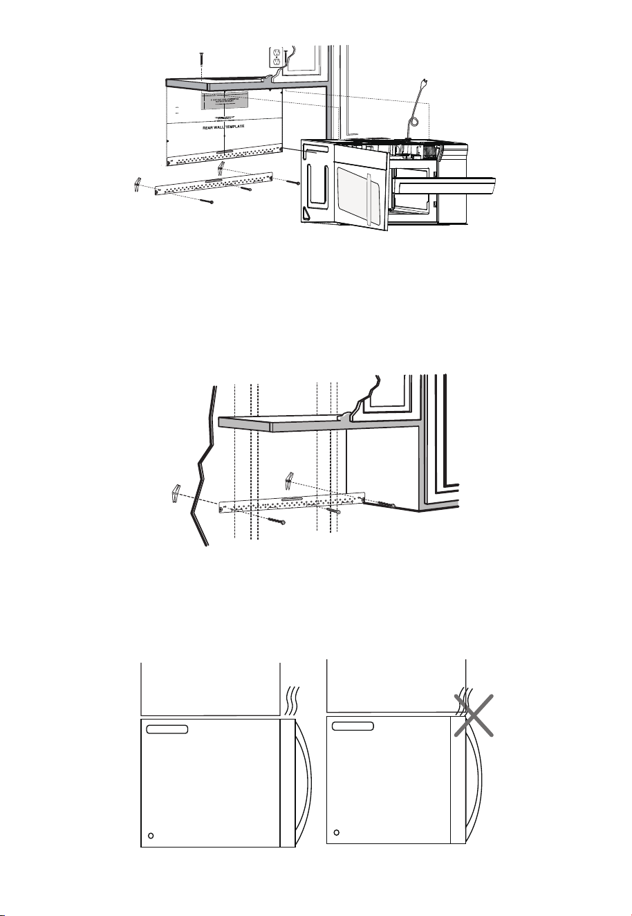
ES-43
12
"
4"
R
N
O
EA
T
D
E
:
A
IT
N
I
D F
S VE
O
L
R
L
Y
O
I
W
MP
T
O
H
E
R
T
D
A
I
R
N
E
T
C
T
T
I
O
O
IN
T
H
E
IN
ST
ALL
AT
I
O
N
I
N
ST
R
U
CTI
O
N
N
S
S
BEF
ORE
PR
O
C
EE
D
INGW
IT
H
T
HI
S
REAR W
ALL
TEM
P
L
AT
E
.
T
e
mp
l
ate
se
rv
e
s t
o
p
mo
t
U
u
le
s
n
t
e
.
ti
1
o
.
u
Th
i
s Re
n
a
g
r
pl
W
a
a
te
l
l
an
d
to
l
o
c
a
t
h
t
e
eh
o
r
i
z
o
o
sit
n
t
i
o
a
l
n
e
t
x
h
h
e
a
b
u
s
ot
t
t
o
m
et
oche
c
k
t
h
a
t
t
h
e
t
emp
l
a
t
e is
p
osition
d
L
oc
ou
n
t
i
n
AN
T:
I
m
MPO
R
T
E
AT
L
at
e
a
g
n
d
pl
a
m
te
a
.
r
k hol
es to
a
lig
n
w
i
t
h hol
e
s
in
t
h
e
LOC
AT
NT
ER
L
E
IN
AS
E
.
T
O
NESTUD
O
N
E
I
T
H
E
R
SID
E
OF
T
H
E
CE
HEL
O
CA
T
I
SP
ACE
AREA.
MARK
T
D
TO
G
GLE
B
O
OL
N F
TS
O
I
R
N
2
T
A
H
D
E
DI
M
T
O
IO
U
N
N
T
AL
I
N
,
E
G
V
P
E
L
N
AT
LY
E
o
unt
i
n
:
L
o
c
a
t
e
a
g
n
d
p
lat
ma
e
.
rk holes t
o
a
l
i
gn
w
i
t
h
h
ol
es
in
t
h
e
I
m
M
P
O
RT
E
A
N
A
T
T
L
LO
C
AT
NT
E
RL
E
I
A
NE
ST
.
O
N
ESTUD
O
N EI
TH
E
R S
IDE
O
F
THECE
H
E
LOCAT
I
SPA
C
A
RE
A
.
MARK
ED
T
T
O
GG
LE
BO
ON
F
L
T
S
OR
IN
2
T
A
H
D
E
DIT
M
O
IO
U
N
N
A
T
I
L
,
N
E
G
VE
P
L
A
NL
T
Y
E
T
r
im
t
h
e
rear
w
a
l
l te
m
p
lat
e
a
lon
g
t
he
d
o
t
ted
l
in
e.
3
/8
"
TO
EDG
E
Trim the re
ar
wall t
em
pla
t
e alongthe dotte
d l
in
e.
L
a
o
c
c
c
a
u
a
t
r
e
a
t
lev
a
el
n
y
e
d
.
l
2
.
m
a
r
k
at
l
ea
st o
nes
tud
on
t
he l
ef
t
o
r
rig
h
t
s
i
de
o
f
the
c
en
te
rl
i
ne
.
It
a
t
rop
mi
s
i
nt
t
o
u
s
e
a
t
l
e
asto
n
e w
o
od
n
t
w
e
a
v
d
f
e
i
.
rm
M
ly
a
r
i
k
n
t
a
w
s
o
t
u
a
d
d
d
t
i
o
t
i
o
s
n
u
a
p
l,
p
o
e
r
v
t
e
t
h
n
e
ly
w
s
p
ei
a
g
h
c
e
t
d
o
o
r
s
i
t
h
nt
e s
h
u
e
p
m
p
l
a
i
r
e
d
ke
t
d
o
l
g
o
g
c
l
a
e
t
b
io
o
l
n
t
s
s
.
.
W
here
th
e
r
e
i
s
l
s
3
o
f
o
.
c
r
c
t
t
t
a
D
a
e
h
h
o
t
r
i
e
s
w
g
a
i
l
o
t
t
l
g
u
n
m
l
m
d
ho
d
s
i
e
o
o
,
c
r
f
l
u
d
e
ril
l
a
3
/16"
h
o
le
fo
r
wood sc
re
w
s
.
F
orho
l
e
s
n ne u
p
with
a
s
tu
d
,
d
r
i
ll5
/8
"
h
o
l
e
sf
o
r
o
l
t
t
N
s.
l
i
OD
bo
TI
NSTALL
TH
E
M
OU
NTI
N
GPL
A
TE
AT
R
T
HI
m
S
v
e
TI
O
M
E.
4
.
e
o
t
h
e
te
m
p
lat
e
f
ro
m
t
h
e
rea
r
wa
ll.
5
.
Re
vie
wth
e
In
s
t
all
a
t
i
on
In
s
t
ruct
i
o
n
b
ook f
or
y
ou
r
in
s
t
a
l
lat
io
n
s
i
t
ua
t
i
o
n.
Darlev
ue
l
ta
a
l
a
ho
ja
pa
r
acons
u
ltar
la
v
e
r
s
ión
e
nEspañol.
NOTAS IMPORTANTES:
1. Asegúrese de que los tornillos para el motor del ventilador y la placa del ventilador
estén bien apretados cuando se vuelvan a instalar. Esto ayudará a evitar vibraciones
excesivas.
2. Asegúrese de que el cableado del motor se haya instalado y asegurado correctamente,
y que los cables no estén aplastados.
C1 FIJACIÓN DE LA PLACA DE MONTAJE A LA PARED
Fije la placa a la pared utilizando pernos de anclaje. Se debe utilizar al menos un tornillo
para madera para fijar la placa a un montante de pared.
Si la profundidad del armario, incluidas las puertas del armario, es superior a 13", entonces
la unidad debe separarse de la pared utilizando materiales adecuados que soporten
150libras para permitir la salida/entrada de aire de ventilación superior adecuada.
Armario Armario
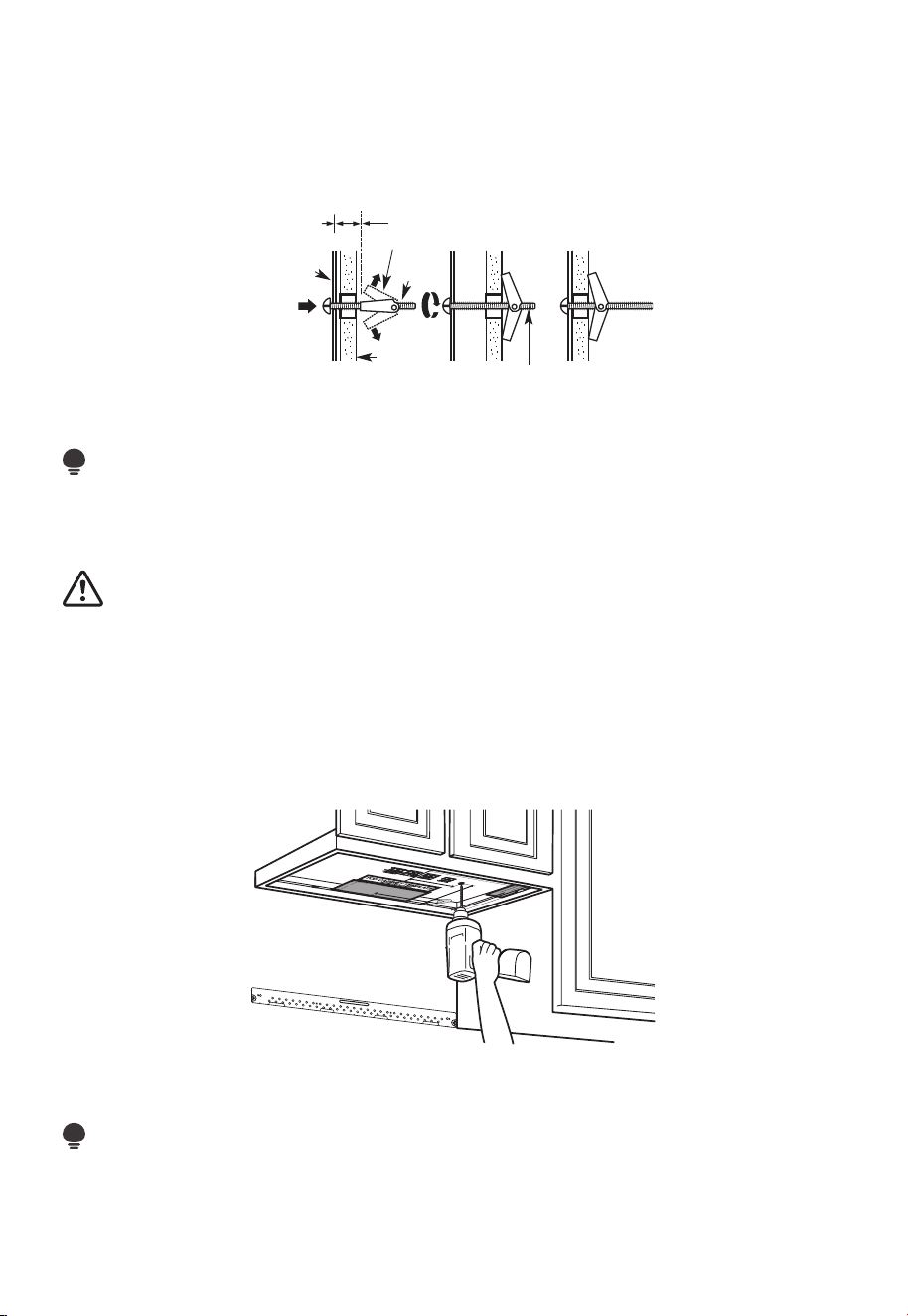
ES-44
1. Retire las alas de anclaje de los pernos.
2. Inserte los pernos en la placa de montaje a través de los orificios designados para la
pared de yeso y vuelva a colocar las alas de anclaje de 3/4" a (19 mm) en cada perno.
Para utilizar pernos de anclaje:
Espaciado para
alternar más que el
grosor de la pared
Alas de perno de anclaje
Perno de
anclaje
Pared
Placa de
montaje
Extremo del perno
3. Coloque la placa de montaje contra la pared e inserte las alas de anclaje en los
orificios de la pared para montar la placa.
NOTA:
Antes de apretar los pernos de anclaje y el tornillo para madera, asegúrese de que la
parte inferior de la placa de montaje toque la parte inferior del armario cuando se empuje
al ras contra la pared y que la placa esté correctamente centrada debajo del armario.
PRECAUCIÓN:
Tenga cuidado de no pillarse los dedos entre la parte posterior de la placa de montaje y
la pared.
4. Apriete todos los tornillos. Retire la placa de la pared para ayudar a apretar los pernos.
C2 UTILICE LA PLANTILLA DEL ARMARIO SUPERIOR PARA LA
PREPARACIÓN DEL ARMARIO SUPERIOR
Es necesario taladrar orificios para los tornillos del soporte superior y un orificio lo
suficientemente grande para que pase el cable de alimentación.
1. Lea las instrucciones de la PLANTILLA DEL ARMARIO SUPERIOR.
2. Péguelo debajo del armario superior.
NOTA:
Ajuste la plantilla superior según corresponda si el microondas está separado de la pared
debido a una profundidad del armario (incluidas las puertas del armario) de más de 13".
Taladre los orificios siguiendo las instrucciones de la PLANTILLA DEL ARMARIO SUPERIOR.
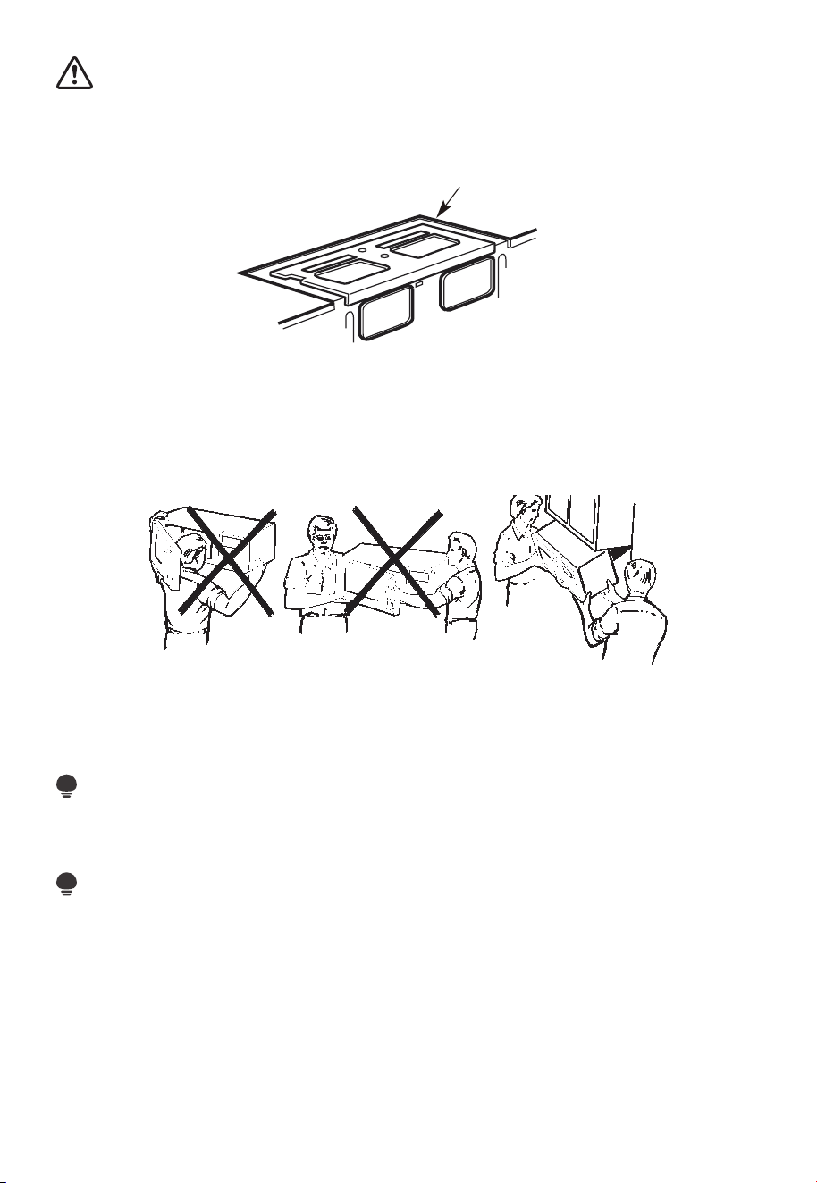
ES-45
PRECAUCIÓN:
Utilice lentes de seguridad cuando taladre orificios en la parte inferior del armario.
C3. COMPROBACIÓN DE LA PLACA DEL VENTILADOR
Placa del ventilador
Coloque el microondas en posición vertical, con la parte superior de la unidad hacia
arriba.
Compruebe que la placa del ventilador esté correctamente instalada en la unidad.
C4. MONTAJE DEL HORNO MICROONDAS
PARA UNA FÁCIL INSTALACIÓN Y SEGURIDAD PERSONAL, RECOMENDAMOS QUE
DOS PERSONAS INSTALEN ESTE HORNO MICROONDAS.
IMPORTANTE: No sujete ni utilice el mango o el protector térmico durante la instalación.
No retire los separadores de cartón entre el protector térmico y la puerta.
NOTA:
Si su armario es de metal, utilice la arandela de nailon alrededor del orificio del cable de
alimentación para evitar que se corte el cable.
NOTA:
Se recomienda utilizar bloques de relleno si la parte delantera del armario cuelga por
debajo del estante inferior del armario.
IMPORTANTE: Si no se utilizan los bloques de relleno, se pueden producir daños en la
carcasa debido a un apriete excesivo de los tornillos.
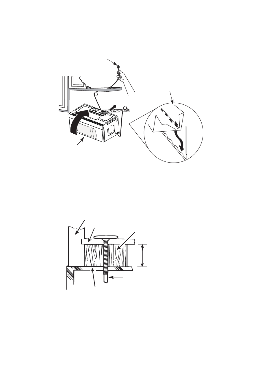
ES-46
NOTA: Al montar el horno
microondas, pase el cable de
alimentación a través del orificio
en la parte inferior del armario
superior. Manténgalo apretado
durante los pasos 1-3. No aplaste
el cable ni levante el horno
tirando del cable.
2. Gire el frente del horno
contra el fondo del armario.
1. Levante el microondas,
inclínelo hacia adelante
y enganche las ranuras
en el borde inferior
posterior en las cuatro
lengüetas inferiores de la
placa de montaje.
3. Inserte un tornillo de autoalineación a través del orificio central superior del armario.
Asegure temporalmente el horno girando el tornillo al menos dos vueltas completas
después de que las roscas hayan encajado (se apretará completamente más tarde).
Asegúrese de mantener apretado el cable de alimentación. Tenga cuidado de no
aplastar el cable, especialmente cuando lo monte al ras de la parte inferior del armario.
Frente del armario
Estante inferior del armario
Bloque de relleno
Equivalente a la
profundidad del
orificio del armario
Tornillo de autoalineación
Parte superior del horno microondas
4. Fije el horno microondas al armario superior.
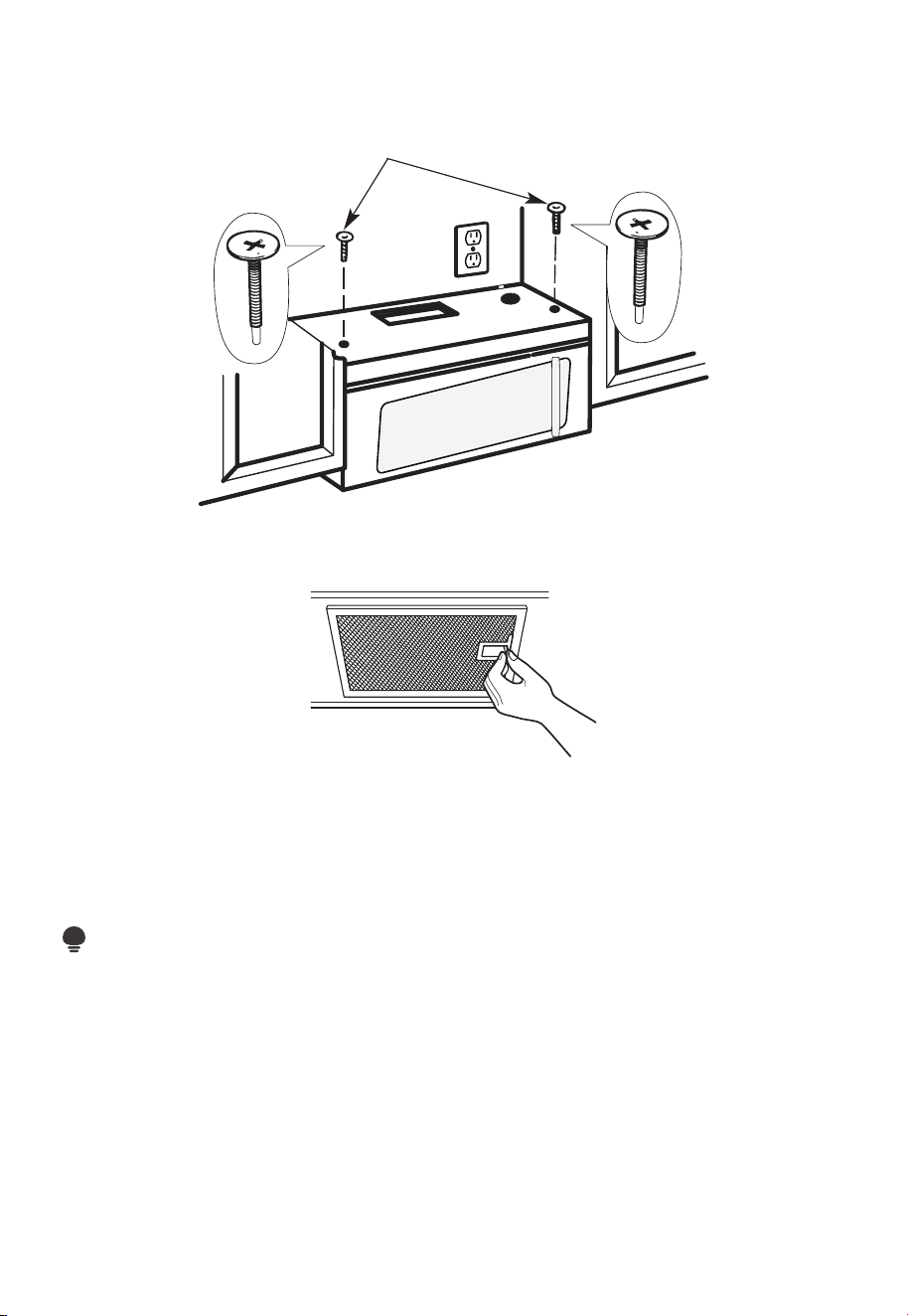
ES-47
5. Inserte 2 tornillos de autoalineación
a través de los orificios exteriores del
armario superior. Gire dos vueltas
completas cada tornillo.
6. Apriete los dos tornillos exteriores a la parte superior del horno microondas. (Mientras
aprieta los tornillos, sujete el horno microondas contra la pared y el armario superior).
7. Instale los filtros de grasa. Consulte la Guía de uso y cuidado incluida con el
microondas.
C5 INSTALACIÓN O CAMBIO DEL FILTRO DE CARBÓN (Algunos modelos)
NOTA:
El filtro de carbón viene instalado de fábrica en algunos modelos. Consulte la Guía de
uso y cuidado para ver si el suyo está instalado de fábrica y para obtener información de
reemplazo.
Para modelos sin puerta de acceso al filtro de recirculación, siga estos pasos para
reemplazar o instalar un filtro de carbón:
1. Desenchufe el horno microondas o desconecte la corriente.
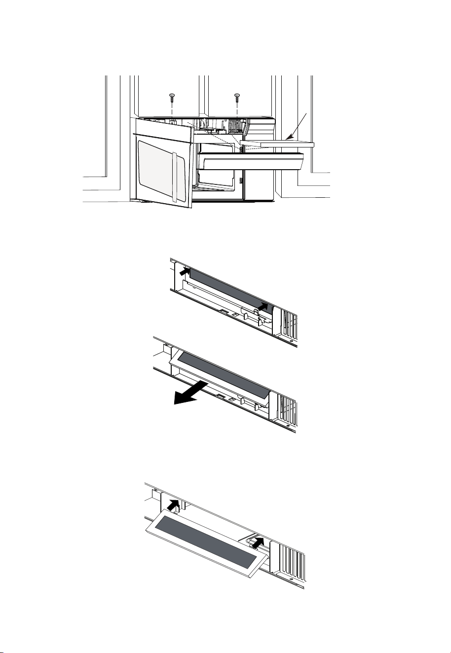
ES-48
2. Abra la puerta del microondas y retire los dos tornillos de montaje de la rejilla de
ventilación ubicados en la parte superior del microondas usando un destornillador
Phillips #1.
Filtro de
carbón
3. Retire el filtro de carbón empujando la parte superior del filtro hacia adentro, luego
tire hacia adelante para sacarlo de la unidad.
4. Deslice la parte superior del nuevo filtro de carbón en la parte superior de la cavidad
del filtro.
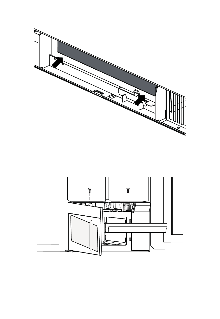
ES-49
5. Presione la parte inferior del filtro de carbón para colocarlo en la posición correcta.
6. Vuelva a instalar la ventilación deslizando la parte inferior de la ventilación en su
lugar. Empuje la parte superior de la ventilación hacia su posición y deslícela hasta
que encaje en su sitio. Vuelva a colocar los dos tornillos de montaje de ventilación
ubicados en la parte superior del microondas con un destornillador Phillips #1.
7. Cierra la puerta del microondas. Enchufe el horno microondas o vuelva a conectar la
alimentación.
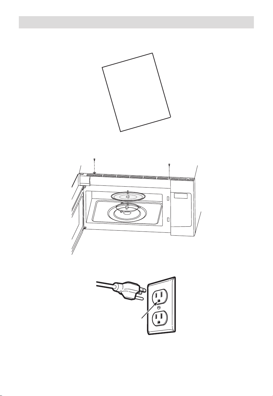
ES-50
Antes de utilizar el microondas
1. Asegúrese de que el horno microondas se haya instalado de acuerdo con las
instrucciones.
USER
MANUAL
2. Retire todo el material de embalaje del horno microondas.
3. Instale el anillo del plato giratorio y la bandeja de vidrio en la cavidad.
4. Enchufe el cable de alimentación en un tomacorriente separado y exclusivo de
15a20amperios.
Asegúrese de que
haya una conexión
a tierra adecuada
antes de usar el
aparato
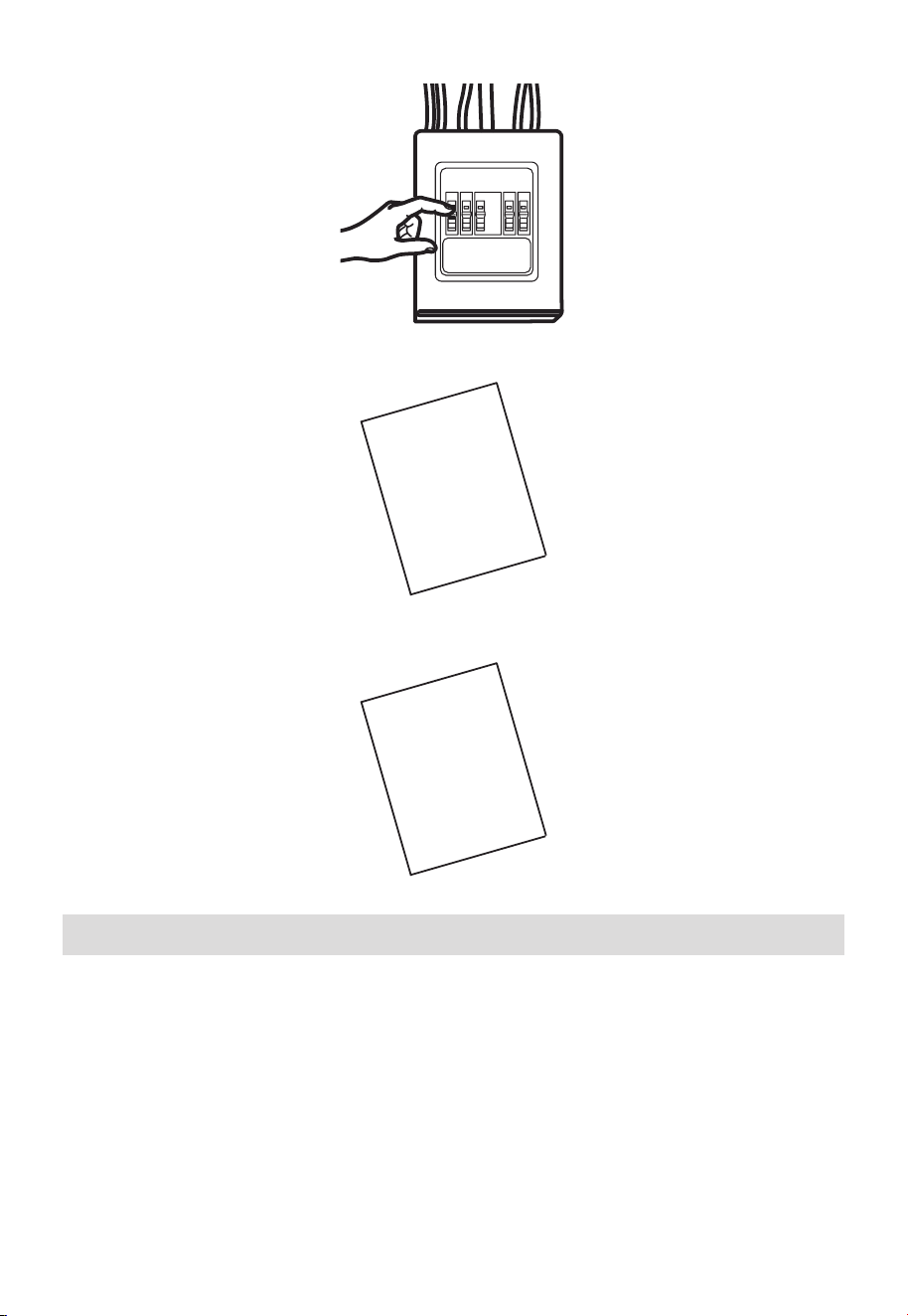
ES-51
5. Reemplace el fusible de la casa o vuelva a encender el disyuntor.
6. Lea el manual del usuario.
USER
MANUAL
7. GUARDE EL MANUAL DEL USUARIO PARA EL USO DEL INSPECTOR LOCAL.
USER
MANUAL
Comprobación de funcionamiento
1. Asegúrese de que la unidad se haya instalado de acuerdo con estas instrucciones.
2. Retire todo el material de embalaje del horno.
3. Reemplace el fusible de la casa o vuelva a encender el disyuntor.
4. Enchufe el cable de alimentación en el tomacorriente.
5. Lea las instrucciones de funcionamiento antes de probar el producto.
6. Encienda el extractor de aire a velocidad Turbo y verifique que esté funcionando
utilizando un pañuelo de papel (se adherirá al filtro).
7. Confirme que la válvula de extracción exterior se haya abierto.
8. Programe el horno microondas durante 1 minuto y verifique que funciona con
normalidad utilizando un vaso de agua.
9. Conserve estas instrucciones de instalación para uso del inspector eléctrico local.
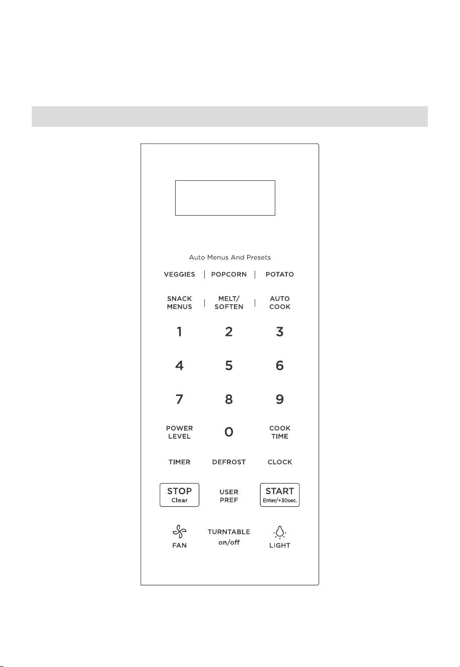
ES-52
INSTRUCCIONES DE
FUNCIONAMIENTO
Panel de control
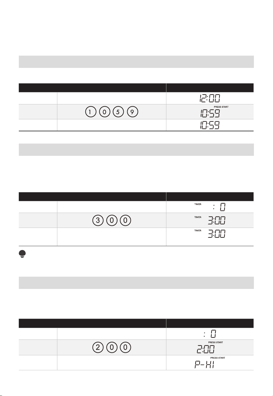
ES-53
• Antes de poner en funcionamiento su nuevo horno microondas, asegúrese de que haya
leído y entendido completamente esta Guía de uso y cuidado.
• El reloj se puede desactivar cuando el microondas se enchufa por primera vez y se
selecciona el botón S /Clear. Para volver a activar el reloj siga las instrucciones del reloj.
Configurar el reloj
• Suponga que desea introducir la hora correcta del día 10:59.
TÁCTIL LA PANTALLA MUESTRA:
1. CLOCK
2.
3. CLOCK o START/Enter/+30sec.
Ajuste del temporizador
El horno microondas se puede utilizar como temporizador de cocina. Puede configurar
hasta 99 minutos, 99 segundos. El temporizador de cocina se puede utilizar mientras el
horno microondas esté funcionando.
• Suponga que desea programar 3 minutos.
TÁCTIL LA PANTALLA MUESTRA:
1. TIMER
2.
3. TIMER
Cuenta regresiva del tiempo
NOTA:
No hay otros programas durante el temporizador de cocina.
Microondas
El horno microondas sobre la cocina se puede programar durante 99 minutos y 99segundos
(99:99). Ingrese siempre los segundos después de los minutos, incluso si ambos son ceros.
• Suponga que desea cocinar durante 2 minutos al 90 % de potencia
TÁCTIL LA PANTALLA MUESTRA:
1. COOK TIME
2.
3. POWER LEVEL X1
TOP
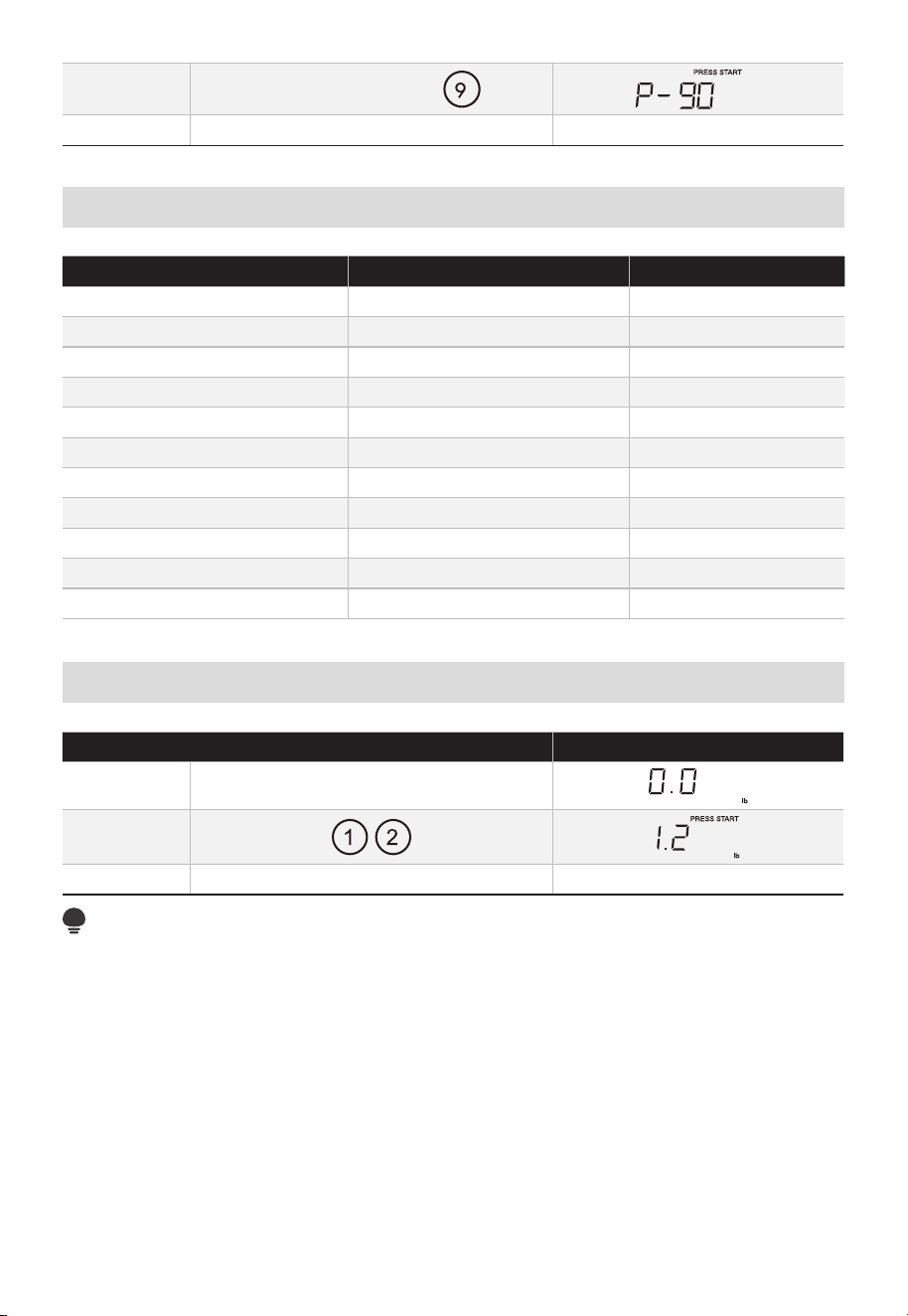
ES-54
4. POWER LEVEL X1 o
5. START/Enter/+30sec. Cuenta regresiva del tiempo
Tabla de potencia
PRESIONE NIVEL DE ALIMENTACIÓN PANTALLA
POWER LEVEL x 1 100% P-HI
POWER LEVEL x 2 o 9 90% P-90
POWER LEVEL x 3 o 8 80% P-80
POWER LEVEL x 4 o 7 70% P-70
POWER LEVEL x 5 o 6 60% P-60
POWER LEVEL x 6 o 5 50% P-50
POWER LEVEL x 7 o 4 40% P-40
POWER LEVEL x 8 o 3 30% P-30
POWER LEVEL x 9 o 2 20% P-20
POWER LEVEL x 10 o 1 10% P-10
POWER LEVEL x 11 o 0 0% P-0
Descongelación por peso
TÁCTIL LA PANTALLA MUESTRA:
1. DEFROST X1
2.
3. START/Enter/+30sec. Cuenta regresiva del tiempo
NOTA:
La cantidad de peso debe ser una entrada válida para que esta función se inicie.
Unaentrada de peso válida es de 0.1 a 6.0 libras.
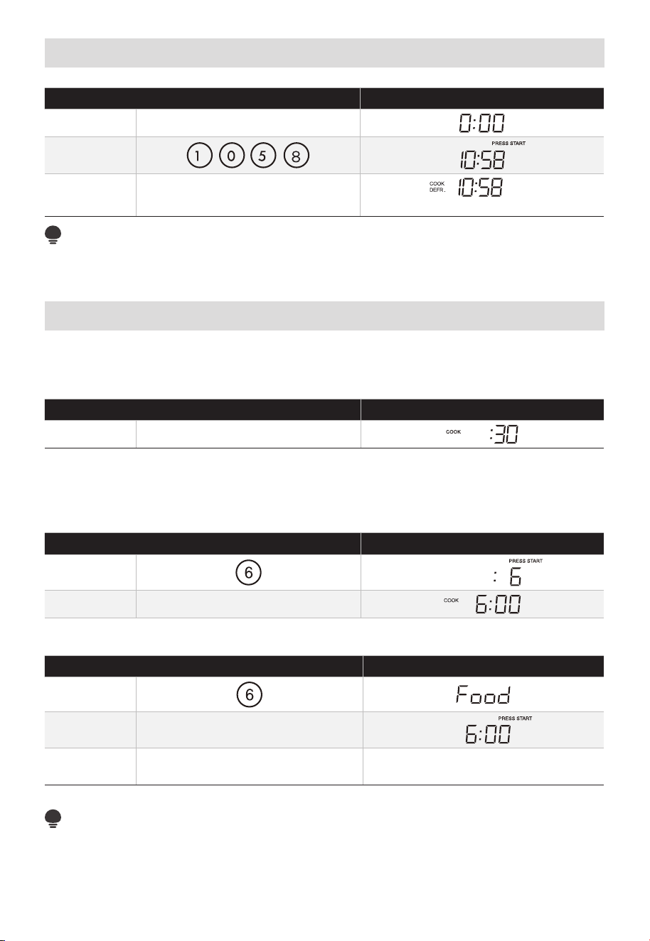
ES-55
Tiempo de descongelación
TÁCTIL LA PANTALLA MUESTRA:
1. DEFROST X2
2.
3. START/Enter/+30sec.
Cuenta regresiva del tiempo
NOTA:
El zumbador sonará para recordarle que debe dar la vuelta a los alimentos cuando haya
transcurrido la mitad del tiempo.
de cocinado
1. Si utiliza agregar 30 segundos:
Esta es una función que permite ahorrar tiempo. Es una función simplificada que le
permite ajustar e iniciar rápidamente la cocción en microondas al 100% de potencia.
TÁCTIL LA PANTALLA MUESTRA:
1. START/Enter/+30sec.
2. Utilice los botones numéricos para "1-6":
Presione las teclas numéricas "1-6" para comenzar a cocinar con el tiempo
correspondiente para un nivel de potencia del 100 % directamente. Por ejemplo,
cocinarcon 6 minutos para un nivel de potencia del 100%.
TÁCTIL LA PANTALLA MUESTRA:
1.
2. Después de 2 segundos
El debe y cerrarse en 5 minutos antes de la de cocinado.
contrario, se debe utilizar como se indica a continuación.
TÁCTIL LA PANTALLA MUESTRA:
1.
2. abrir la puerta
3. START/Enter/+30sec.
Cuenta regresiva del tiempo
(cerrarla puerta)
NOTA:
Si no se selecciona un ciclo de cocción rápida o el botón "START/Enter/+30sec." dentro
de los 5 minutos de que se hayan colocado los alimentos en el microondas, se mostrará
"Alimentos". Debe abrir y volver a cerrar la puerta para borrar "Alimentos" de la pantalla.
Rápido
puerta del horno
abierto
rápido
De lo
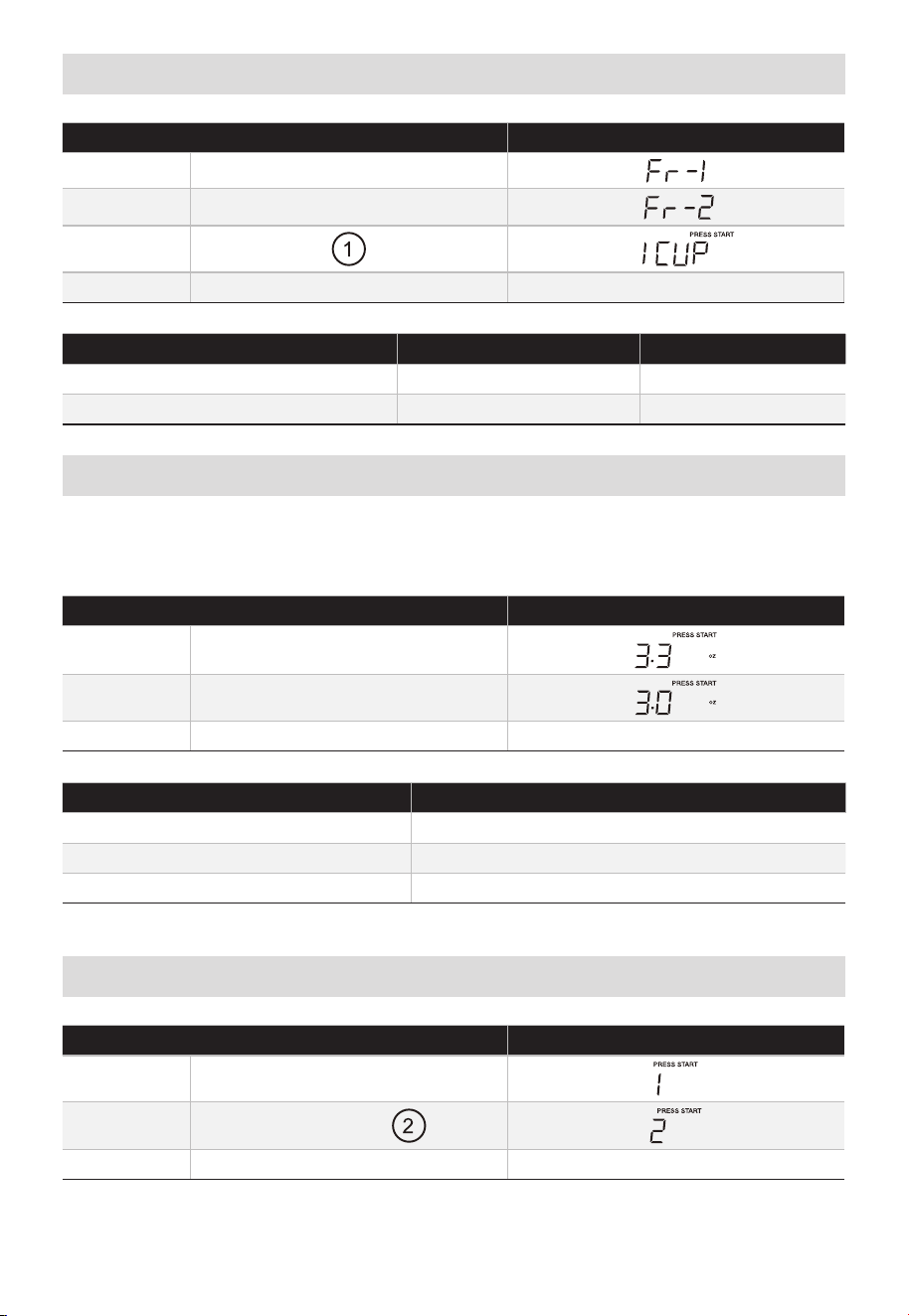
ES-56
Vegetales
TÁCTIL LA PANTALLA MUESTRA:
1. VEGGIES X1
2. VEGGIES X1
3.
4. START/Enter/+30sec. Cuenta regresiva del tiempo
PRESIONE EL BOTÓN VEGETALES ALIMENTO CANTIDAD
X1 Vegetales frescos 1 - 4 tazas
X2 Vegetales congelados 1 - 4 tazas
Palomitas
Presione el botón "POPCORN" y el LED mostrará 3.3 oz. Presione “POPCORN”
repetidamente para elegir el peso deseado.
• Suponga que desea cocinar 3.0 oz de palomitas.
TÁCTIL LA PANTALLA MUESTRA:
1. POPCORN X1
2. POPCORN X1
3. START/Enter/+30sec. Cuenta regresiva del tiempo
PRESIONE EL BOTÓN PALOMITAS CANTIDAD
X1 3.3 oz
X2 3.0 oz
X3 1.75 oz
Patata
TÁCTIL LA PANTALLA MUESTRA:
1. POTATO X1
2. POTATO X1 o
3. START/Enter/+30sec. Cuenta regresiva del tiempo
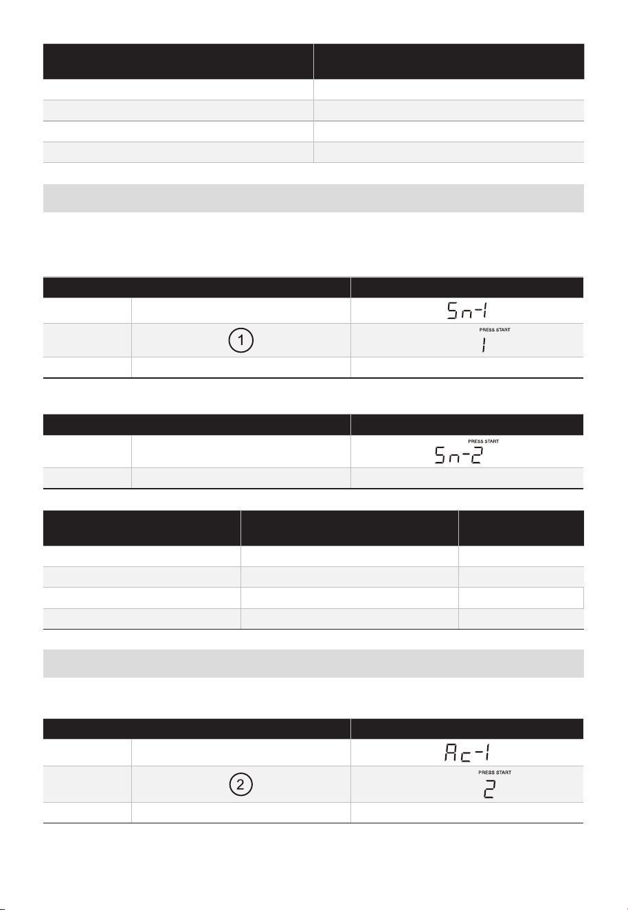
ES-57
PRESIONE EL TECLADO DE PATATAS O
LAS TECLAS NUMÉRICAS
CANTIDAD
X1 1
X2 2
X3 3
X4 4
Menús de aperitivos
Hay 4 opciones (Hot dogs, Comida congelada para niños, Comida en una taza, Sopa)
enel menú de aperitivos.
1. Hot dogs o Sopa
TÁCTIL LA PANTALLA MUESTRA:
1. SNACK MENUS X1
2.
3. START/Enter/+30sec. Cuenta regresiva del tiempo
2. Comida congelada para niños o comida en una taza
TÁCTIL LA PANTALLA MUESTRA:
1. SNACK MENUS X2
2. START/Enter/+30sec. Cuenta regresiva del tiempo
PRESIONE EL TECLADO DE
MENÚS DE SNACK
ALIMENTO CANTIDAD
X1 Hot Dogs 1 - 6 piezas
X2 Comida congelada para niños 8.8 oz
X3 Comida en una taza 2.39 oz
X4 Sopa 1 - 2 tazas
Cocción automática
Hay 5 opciones (tocino, plato de cena, arroz, desayuno congelado, pizza congelada) enla
función de cocción automática.
TÁCTIL LA PANTALLA MUESTRA:
1. AUTO COOK X1
2.
3. START/Enter/+30sec. Cuenta regresiva del tiempo
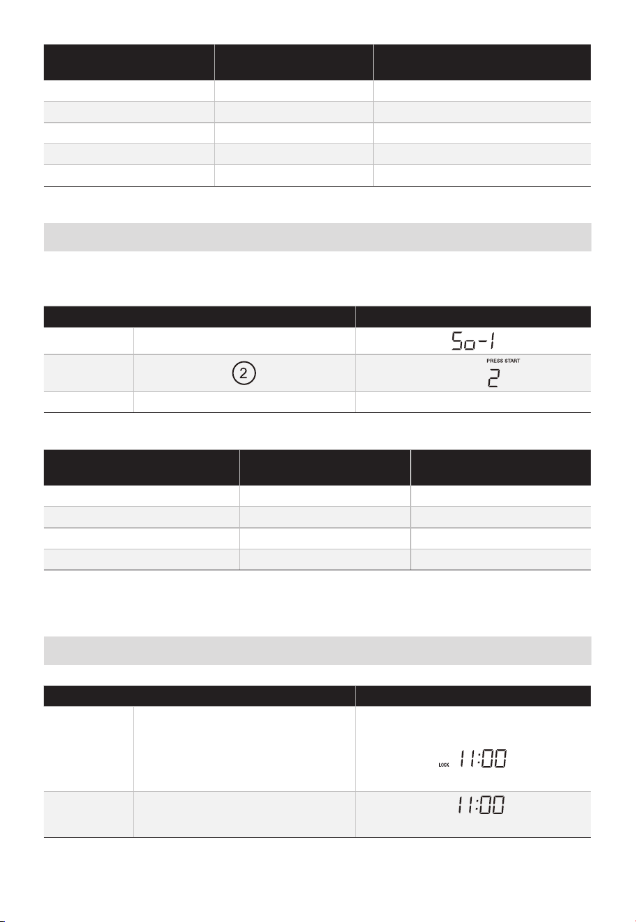
ES-58
PRESIONE COCCIÓN
AUTOMÁTICA
ALIMENTO CANTIDAD
X1 Tocino 1-3 pedazos
X2 Plato de cena 1-2 platos
X3 Arroz 1-2 tazas
X4 Desayuno congelado 8/12 oz
X5 Pizza congelada 6/8/12 oz
Derretir/Ablandar
El horno utiliza baja potencia para derretir y ablandar alimentos. Vea la siguiente tabla.
• Suponga que desea derretir 2 barras de mantequilla.
TÁCTIL LA PANTALLA MUESTRA:
1. MELT/SOFTEN X 1
2.
3. START/Enter/+30sec. Cuenta regresiva del tiempo
PRESIONE EL BOTÓN
DERRETIR/ABLANDAR
ALIMENTO CANTIDAD
X1 Derretir mantequilla 1/2 barras
X2 Derretir chocolate 2/4/8 oz
X3 Suavizar helado Pinta/1.5 cuartos
X4 Suavizar queso crema 3/8 oz
Bloqueo infantil
TÁCTIL LA PANTALLA MUESTRA:
1.
STOP/Clear
(durante 3 segundos)
O
(si el reloj está configurado)
2.
STOP/Clear
(durante 3 segundos)
(si el reloj está configurado)
LOCK
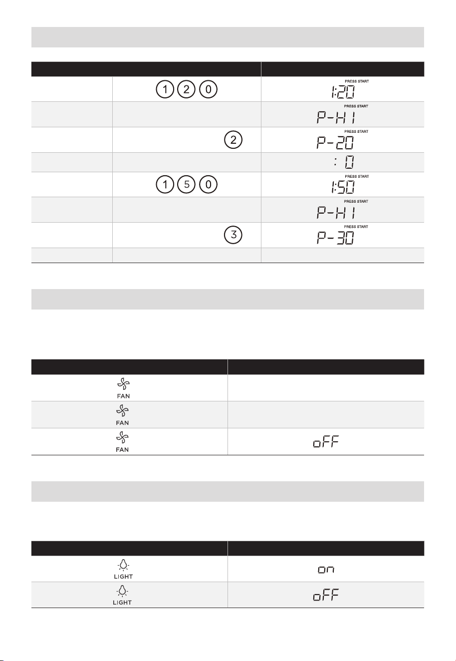
ES-59
Cocción por etapas
TÁCTIL LA PANTALLA MUESTRA:
1.
2. POWER LEVEL X1
3. POWER LEVEL X8 o
4. COOK TIME
5.
6. POWER LEVEL X1
7. POWER LEVEL X7 o
8. START/Enter/+30sec. Cuenta regresiva del tiempo
Ventilador
Este botón controla el ventilador de 2 velocidades. Si el ventilador está APAGADO,
elprimer toque del botón VENTILADOR encenderá el ventilador en ALTO, el segundo
toque en BAJO y el tercer toque en APAGADO.
TÁCTIL LA PANTALLA MUESTRA:
X1
X2
X3
Iluminación
Este botón controla la luz de 2 estados. Si la luz está APAGADA, el primer toque del
botón encenderá la luz, el segundo toque la APAGARÁ.
TÁCTIL LA PANTALLA MUESTRA:
X1
X2
VENT HI
VENT LOW
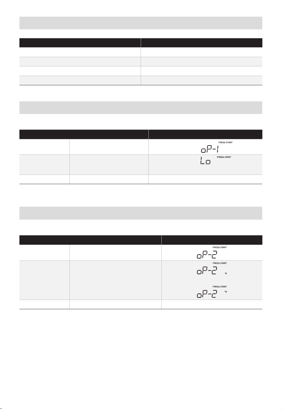
ES-60
Pref de usuario
BOTÓN CONFIGURACIÓN
USER PREF X1 Volumen Lo/Nor/Hi/Off
USER PREF X2 Peso lb/kg
USER PREF X3 Desactivar/activar visualización del reloj
USER PREF X4 Modo Demo
Volumen:
En modo de espera
TÁCTIL LA PANTALLA MUESTRA:
1. USER PREF X1
2. START/Enter/+30sec.
(Lo, nor, HI, OFF se mostrarán en orden)
3. START/Enter/+30sec.
Peso (lb/kg)
En modo de espera
TÁCTIL LA PANTALLA MUESTRA:
1. USER PREF X2
2. START/Enter/+30sec.
O
3. START/Enter/+30sec.
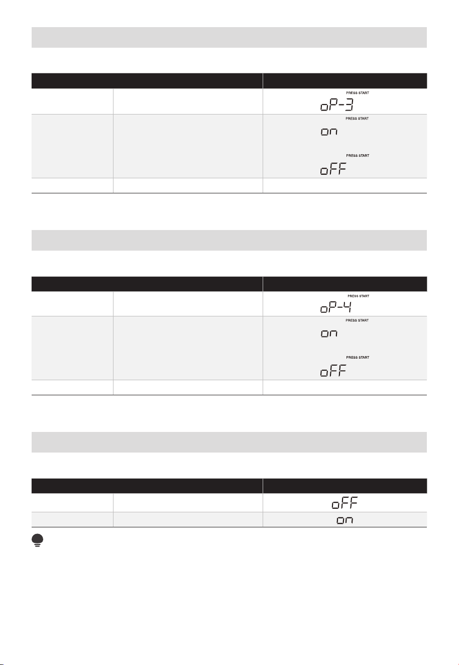
ES-61
Desactivar/activar visualización del reloj
En modo de espera
TÁCTIL LA PANTALLA MUESTRA:
1. USER PREF X3
2. START/Enter/+30sec.
O
3. START/Enter/+30sec.
Modo Demo
En modo de espera
TÁCTIL LA PANTALLA MUESTRA:
1. USER PREF X4
2. START/Enter/+30sec.
O
3. START/Enter/+30sec.
Activar/desactivar plato giratorio
El estado predeterminado del plato giratorio está activado.
TÁCTIL LA PANTALLA MUESTRA:
1. TURNTABLE on/off X1
2. TURNTABLE on/off X1
NOTA:
El plato giratorio no puede controlarse en el menú automático ni en el modelo de cocción
de descongelación.
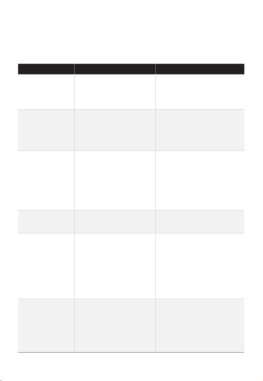
ES-62
PROBLEMAS Y SOLUCIONES
Verifique el problema utilizando la siguiente tabla y pruebe las soluciones para cada
problema. Si el horno microondas aún no funciona correctamente, póngase en contacto
con el centro de servicio autorizado más cercano.
PROBLEMA POSIBLE CAUSA POSIBLE SOLUCIÓN
El horno no enciende
• El cable eléctrico del horno
no está enchufado.
• La puerta está abierta.
• Se estableció una operación
incorrecta.
• Conecte el horno al
tomacorriente.
• Cierre la puerta e inténtelo de
nuevo.
• Verifique las instrucciones.
Arcos eléctricos y
chispas
• Se utilizaron materiales no
aptos para horno microondas.
• El horno funciona cuando
está vacío.
• Quedan restos de comida en
el interior del horno.
• Utilice únicamente utensilios de
cocina aptos para microondas.
• No utilice el horno microondas
vacío.
• Limpie el interior del horno con
una toalla húmeda.
Alimentos cocidos
de forma desigual
• Se utilizaron materiales no
aptos para horno microondas.
• La comida no se descongela
completamente.
• El tiempo de cocción y el
nivel de potencia no son
adecuados.
• La comida no se da vuelta ni
se revuelve.
• Utilice únicamente utensilios de
cocina aptos para microondas.
• Descongele completamente los
alimentos.
• Utilice el tiempo de cocción y el
nivel de potencia adecuados.
• Voltee o revuelva los alimentos.
Alimentos
sobrecocidos
• El tiempo de cocción y el
nivel de potencia no son
adecuados.
• Utilice el tiempo de cocción y el
nivel de potencia adecuados.
Alimentos mal
cocidos
• Se utilizaron materiales
no aptos para horno
microondas.
• La comida no se descongela
completamente.
• Los puertos de ventilación
del horno están obstruidos.
• El tiempo de cocción y el
nivel de potencia no son
adecuados.
• Utilice únicamente utensilios de
cocina aptos para microondas.
• Descongele completamente los
alimentos.
• Verifique que los puertos de
ventilación del horno no estén
obstruidos.
• Utilice el tiempo de cocción y el
nivel de potencia adecuados.
Descongelación
incorrecta
• Se utilizaron materiales
no aptos para horno
microondas.
• El tiempo de cocción y el
nivel de potencia no son
adecuados.
• La comida no se da vuelta ni
se revuelve.
• Utilice únicamente utensilios de
cocina aptos para microondas.
• Utilice el tiempo de cocción y el
nivel de potencia adecuados.
• Voltee o revuelva los alimentos.

ES-63
MARCAS REGISTRADAS,
DERECHOS DE AUTOR Y
DECLARACIÓN LEGAL
El logotipo , las marcas denominativas, el nombre comercial, la imagen
comercial y todas las versiones de los mismos son activos valiosos de Midea Group y/o
sus empresas afiliadas (“Midea”), de las que Midea posee marcas registradas, derechos
de autor y otros derechos de propiedad intelectual, así como toda la buena voluntad
derivada del uso de cualquier parte de una marca comercial de Midea. El uso de la marca
registrada de Midea para fines comerciales, sin el consentimiento previo por escrito de
Midea puede constituir una violación de la marca registrada o una competencia desleal
violando la legislación relevante.
Midea ha creado este manual y se reserva todos los derechos sobre el mismo. Ninguna
entidad o individuo puede usar, duplicar, modificar, distribuir en todo o en parte este
manual, o unirlo o venderlo con otros productos sin el consentimiento previos por escrito
de Midea.
Todas las funciones e instrucciones descritas se actualizan en el momento de la impresión
de este manual. Sin embargo, el producto real puede variar debido a funciones y diseños
mejorados.

ES-64
AVISO DE PROTECCIÓN DE DATOS
Para la prestación de los servicios acordados con el cliente,
nos comprometemos a cumplir sin restricciones todas las estipulaciones de la ley de
protección de datos aplicable, de conformidad con los países acordados en los que se
prestarán los servicios al cliente.
En general, nuestro procesamiento de datos es para cumplir con nuestras obligaciones
contractuales con usted y por motivos de seguridad de los productos, para salvaguardar
sus derechos en relación con la garantía y preguntas del registro del producto. En
algunos casos, pero solo si se garantiza la protección de datos apropiada, se podrían
transferir los datos personales a receptores ubicados fuera del Área Económica Europea.
Se proporciona más información bajo solicitud. Puede ponerse en contacto con
nuestro Oficial de Protección de Datos usando [email protected]. Para ejercitar
sus derechos como el derecho a rechazar que se procesen sus datos personales para
una finalidad directa de marketing, póngase en contacto con nosotros en el correo
[email protected]. Para obtener más información, siga el código QR.