
USER MANUAL
Warning notices: Before using this product, please read this manual carefully and keep it for future reference.
The design and specifications are subject to change without prior notice for product improvement. Consult
with your dealer or manufacturer for details.
The diagram above is just for reference. Please take the appearance of the actual product as the standard.
MMO19S14ASTC
Household Microwave Oven

EN-01
THANK YOU LETTER ---------------------------------------------EN-01
SAFETY INSTRUCTIONS-----------------------------------------EN-02
SPECIFICATION ---------------------------------------------------EN-11
PRODUCT OVERVIEW -------------------------------------------EN-12
PRODUCT INSTALLATION --------------------------------------EN-13
OPERATION INSTRUCTIONS -----------------------------------EN-51
TROUBLESHOOTING ---------------------------------------------EN-83
TRADEMARKS, COPYRIGHTS AND LEGAL STATEMENT ---EN-84
DATA PROTECTION NOTICE ------------------------------------ EN-85
CONTENTS
THANK YOU LETTER
Thank you for choosing Midea! Before using your new Midea product, please
read this manual thoroughly to ensure that you know how to operate the
features and functions that your new appliance offers in a safe way.
EN-02
SAFETY INSTRUCTIONS
Intended Use
The following safety guidelines are intended to prevent unforeseen risks or damage from
unsafe or incorrect operation of the appliance. Please check the packaging and appliance
on arrival to make sure everything is intact to ensure safe operation. If you find any
damage, please contact the retailer or dealer. Please note modifications or alterations
to the appliance are not allowed for your safety concern. Unintended use may cause
hazards and loss of warranty claims.
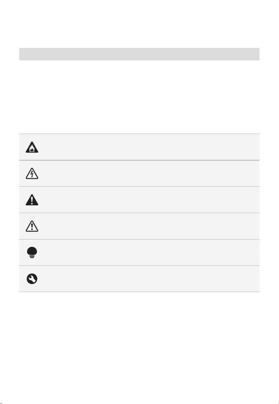
Explanation of Symbols
Danger
This symbol indicates that there are dangers to the life and health of persons due
to extremely flammable gas.
Warning of electrical voltage
This symbol indicates that there is a danger to life and health of persons due to
voltage.
Warning
The signal word indicates a hazard with a medium level of risk which, if not
avoided, may result in death or serious injury.
Caution
The signal word indicates a hazard with a low degree of risk which, if not avoided,
may result in minor or moderate injury.
Attention
The signal word indicates important information (e.g. damage to property), but
not danger.
Observe instructions
This symbol indicates that a service technician should only operate and maintain
this appliance in accordance with the operating instructions.
Read these operating instructions carefully and attentively before using/commissioning the
unit and keep them in the immediate vicinity of the installation site or unit for later use.

EN-03
PRECAUTIONS TO AVOID
POSSIBLE EXPOSURE TO
EXCESSIVE MICROWAVE
ENERGY
a. Do not attempt to operate this oven with the door
open since open door operation can result in harmful
exposure to microwave energy.
It is important not to defeat or tamper with the
safety interlocks.
b. Do not place any object between the oven front
face and the door or allows soil or cleaner residue to
accumulate on sealing surfaces.
c. Do not operate the oven if it is damaged. It is
particularly important that the oven door close
properly and that there is no damage to the:
-
DOOR (bent)
-
HINGES AND LATCHES (broken or loosened)
-
DOOR SEALS AND SEALING SURFACES
d. The oven should not be adjusted or repaired by
anyone except properly qualified service personnel.

EN-04
IMPORTANT SAFETY
INSTRUCTIONS
When using electrical appliances basic safety precautions
should be followed, including the following:
WARNING
To reduce the risk of burns, electric shock, fire, injury
to persons or exposure to excessive microwave energy:
• Read all instructions before using the appliance.
• Read and follow the specific: "PRECAUTIONS
TO AVOID POSSIBLE EXPOSURE TO EXCESSIVE
MICROWAVE ENERGY" found on page 03.
• This appliance must be grounded. Connect only
to properly grounded outlet. See "GROUNDING
INSTRUCTIONS" found on page 07.
• Install or locate this appliance only in accordance
with the provided installation instructions.
• Some products such as whole eggs and sealed
containers - for example, closed glass jars - are able
to explode and should not be heated in this oven.
• Use this appliance only for its intended use as
described in the manual. Do not use corrosive
chemicals or vapors in this appliance. This type of oven
is specifically designed to heat, cook or dry food. It is
not designed for industrial or laboratory use.
• HOT CONTENTS CAN CAUSE SEVERE BURNS. DO
NOT ALLOW CHILDREN TO USE THE MICROWAVE.
Use caution when removing hot items.
• Do not operate this appliance if it has a damaged
cord or plug, if it is not working properly, or if it has
been damaged or dropped.

EN-05
• This appliance should be serviced only by qualified
service personnel. Contact nearest authorized service
facility for examination, repair, or adjustment.
• Do not cover or block any openings on the appliance.
• Do not store this appliance outdoors. Do not use this
product near water - for example, near a kitchen sink,
in a wet basement, near a swimming pool, or similar
location.
• Do not immerse cord or plug in water.
• Keep cord away from heated surface.
• Do not let cord hang over edge of table or counter.
• When cleaning surfaces of door and oven that
comes together on closing the door, use only mild,
nonabrasive soaps, or detergent applied with a
sponge or soft cloth.
• To reduce the risk of fire in the oven cavity:
-
Do not overcook food. Carefully attend appliance
when paper, plastic, or other combustible materials
are placed inside the oven to facilitate cooking.
-
Remove wire twist-ties from paper or plastic bag
before placing bag in oven.
-
If material inside of the oven ignite, keep oven
door closed, turn oven off, and disconnect the
power cord, or shut off power at the fuse or circuit
breaker panel.
-
Do not use the cavity for storage purposes. Do not
leave paper products, cooking utensils, or food in
the cavity when not in use.
• Liquids, such as water, coffee, or tea are able to
be overheated beyond the boiling point without
appearing to be boiling. Visible bubbling or boiling
when the container is removed from the microwave
oven is not always present.

EN-06
THIS COULD RESULT IN VERY HOT LIQUID
SUDDENLY BOILING OVER WHEN THE CONTAINER
IS DISTURBED OR A UTENSIL IS INSERTED INTO
THE LIQUID. To reduce the risk of injury to persons:
-
Do not overheat the liquid.
-
Stir the liquid both before and halfway through
heating it.
-
Do not use straight-sided containers with narrow
necks.
-
After heating, allow the container to stand in the
microwave oven for a short time before removing
the container.
-
Use extreme care when inserting a spoon or other
utensil into the container.
• Oversized food or oversized metal utensils should
not be inserted in a microwave/toaster oven as they
may create a fire or risk of electric shock.
• Do not clean with metal scouring pads. Pieces can
burn off the pad and touch electrical parts involving
a risk of electric shock.
• Do not use paper products when appliance is
operated in the toaster mode.
• Do not store any materials, other than manufacturer's
recommended accessories, in this oven when not in
use.
• Do not cover racks or any other part of the oven with
metal foil. This will cause overheating of the oven.
• Clean Ventilation Hoods Frequently - Grease should
not be allowed to accumulate on hood or filter.
• When flaming foods under the hood, turn the fan on.
• Use care when cleaning the vent-hood filter.
Corrosive cleaning agents, such as lyebased oven
cleaners, may damage the filter.

EN-07
• Suitable for use above both gas and electric cooking
equipment.
SAVE THESE INSTRUCTIONS
GROUNDING INSTRUCTIONS
This appliance must be grounded. In the event of an
electrical short circuit, grounding reduces the risk of
electric shock by providing an escape wire for the
electric current. This appliance is equipped with a cord
having a grounding wire with a grounding plug. The
plug must be plugged into an outlet that is properly
installed and grounded.
WARNING
Improper use of the grounding can result in a risk
of electric shock. Consult a qualified electrician or
serviceman if the grounding instructions are not
completely understood, or if doubt exists as to
whether the appliance is properly grounded. If it is
necessary to use an extension cord, use only a 3-wire
extension cord that has a 3-blade grounded plug,
and 3-slot receptacle that will accept the plug on the
appliance. The marked rating of the extension cord
shall be equal to or greater than the electrical rating of
the appliance.
DANGER
Electric Shock Hazard
Touching some of the internal components can cause
serious personal injury or death. Do not disassemble
this appliance.

EN-08
WARNING
Electric Shock Hazard
Improper use of the grounding can result in electric
shock. Do not plug into an outlet until appliance is
properly installed and grounded.
• A short power-supply cord is provided to reduce
the risks resulting from becoming entangled in or
tripping over a longer cord.
• Longer cord sets or extension cords are available and
may be used if care is exercised in their use.
• If a long cord or extension cord is used:
-
The marked electrical rating of the cord set or
extension cord should be at least as great as the
electrical rating of the appliance.
-
The extension cord must be a grounding-type
3-wire cord.
-
The longer cord should be arranged so that it will
not drape over the counter top or tabletop where
it can be pulled on by children or tripped over
unintentionally.
RADIO INTERFERENCE
• Operation of the microwave oven may cause
interference to your radio, TV or similar equipment.
• When there is interference, it may be reduced or
eliminated by taking the following measures:
-
Clean door and sealing surface of the oven
-
Reorient the receiving antenna of radio or
television.
-
Relocate the microwave oven with respect to the
receiver.
-
Move the microwave oven away from the receiver.
EN-09
-
Plug the microwave oven into a different outlet so
that microwave oven and receiver are on different
branch circuits.
THIS DEVICE COMPLIES WITH
PART 18 OF THE FCC RULES.
UTENSILS
CAUTION
Personal Injury Hazard
Tightly-closed utensils could explode. Closed
containers should be opened and plastic pouches
should be pierced before cooking.
See the instructions on "Materials you can use in
microwave oven or to be avoided in microwave oven."
There may be certain non-metallic utensils that are not
safe to use for microwaving. If in doubt, you can test
the utensil in question following the procedure below.
Utensil Test:
• Fill a microwave-safe container with 1 cup of cold
water (250ml) along with the utensil in question.
• Cook on maximum power for 1 minute.
• Carefully feel the utensil. If the empty utensil is warm,
do not use it for microwave cooking.
• Do not exceed 1 minute cooking time.
EN-10
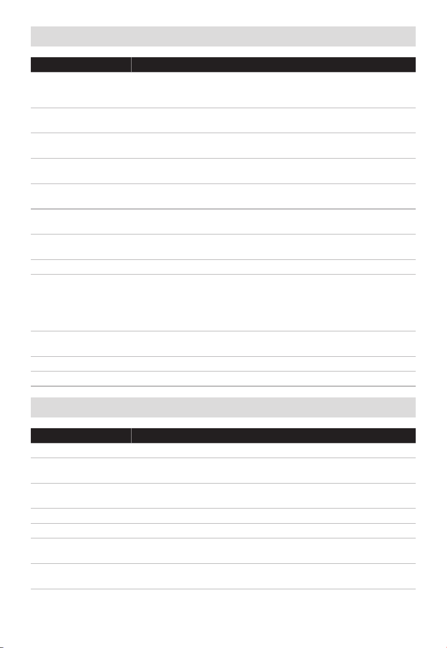
Materials you can use in microwave oven
Utensils Remarks
Browning dish
Follow manufacturer’s instructions. The bottom of browning
dish must be at least 3/16 inch (5mm) above the turntable.
Incorrect usage may cause the turntable to break.
Dinnerware
Microwave-safe only. Follow manufacturer's instructions. Do not
use cracked or chipped dishes.
Glass jars
Always remove lid. Use only to heat food until just warm.
Most glass jars are not heat resistant and may break.
Glassware
Heat-resistant oven glassware only. Make sure there is no
metallic trim. Do not use cracked or chipped dishes.
Oven cooking bags
Follow manufacturer’s instructions. Do not close with metal tie.
Make slits to allow steam to escape.
Paper plates and
cups
Use for short–term cooking/warming only. Do not leave oven
unattended while cooking.
Paper towels
Use to cover food for reheating and absorbing fat. Use with
supervision for a short-term cooking only.
Parchment paper Use as a cover to prevent splattering or a wrap for steaming.
Plastic
Microwave-safe only. Follow the manufacturer’s instructions.
Should be labeled "Microwave Safe". Some plastic containers
soften, as the food inside gets hot. "Boiling bags" and tightly
closed plastic bags should be slit, pierced or vented as directed
by package.
Plastic wrap
Microwave-safe only. Use to cover food during cooking to retain
moisture. Do not allow plastic wrap to touch food.
Thermometers Microwave-safe only (meat and candy thermometers).
Wax paper Use as a cover to prevent splattering and retain moisture.
Materials to be avoided in microwave oven
Utensils Remarks
Aluminum tray May cause arcing. Transfer food into microwave-safe dish.
Food carton with
metal handle
May cause arcing. Transfer food into microwave-safe dish.
Metal or metal-
trimmed utensils
Metal shields the food from microwave energy. Metal trim may
cause arcing.
Metal twist ties May cause arcing and could cause a fire in the oven.
Paper bags May cause a fire in the oven.
Plastic foam
Plastic foam may melt or contaminate the liquid inside when
exposed to high temperature.
Wood
Wood will dry out when used in the microwave oven and may
split or crack.

EN-11
SPECIFICATION
MODEL
Rated Voltage/Frequency 120VAC 60Hz
Rated Input(Microwave) 1500 W
Rated Output(Microwave) 1000 W
MMO19S14ASTC
EN-12
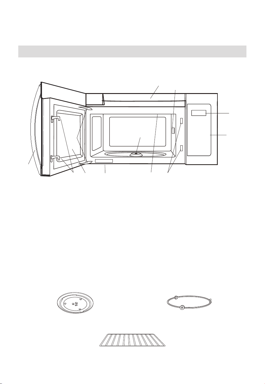
PRODUCT OVERVIEW
Setting Up Your Oven
PART NAMES
9
8
10
3
6
4
11
1
2
7
6
5
1. Microwave oven door with see-through window
2. Door hinges
3. Waveguide cover: DO NOT REMOVE.
4. Turntable motor shaft
5. Microwave oven light
It will light when microwave oven is operating or door is open.
6. Safety door latches
The microwave oven will not operate unless the door is securely closed.
7. Handle
8. Control panel
9. Display
10. Ventilation openings
11. Rating label
Glass turntable Turntable Ring Assembly
Rack for
2-level cooking/
reheating
EN-13
PRODUCT INSTALLATION
Important Safety Instructions
This product requires a three-prong grounded outlet. The installer must perform a
ground continuity check on the power outlet box before beginning the installation to
ensure that the outlet box is properly grounded. If not properly grounded, or if the outlet
box does not meet electrical requirements noted (under ELECTRICAL REQUIREMENTS),
a qualified electrician should be employed to correct any deficiencies.
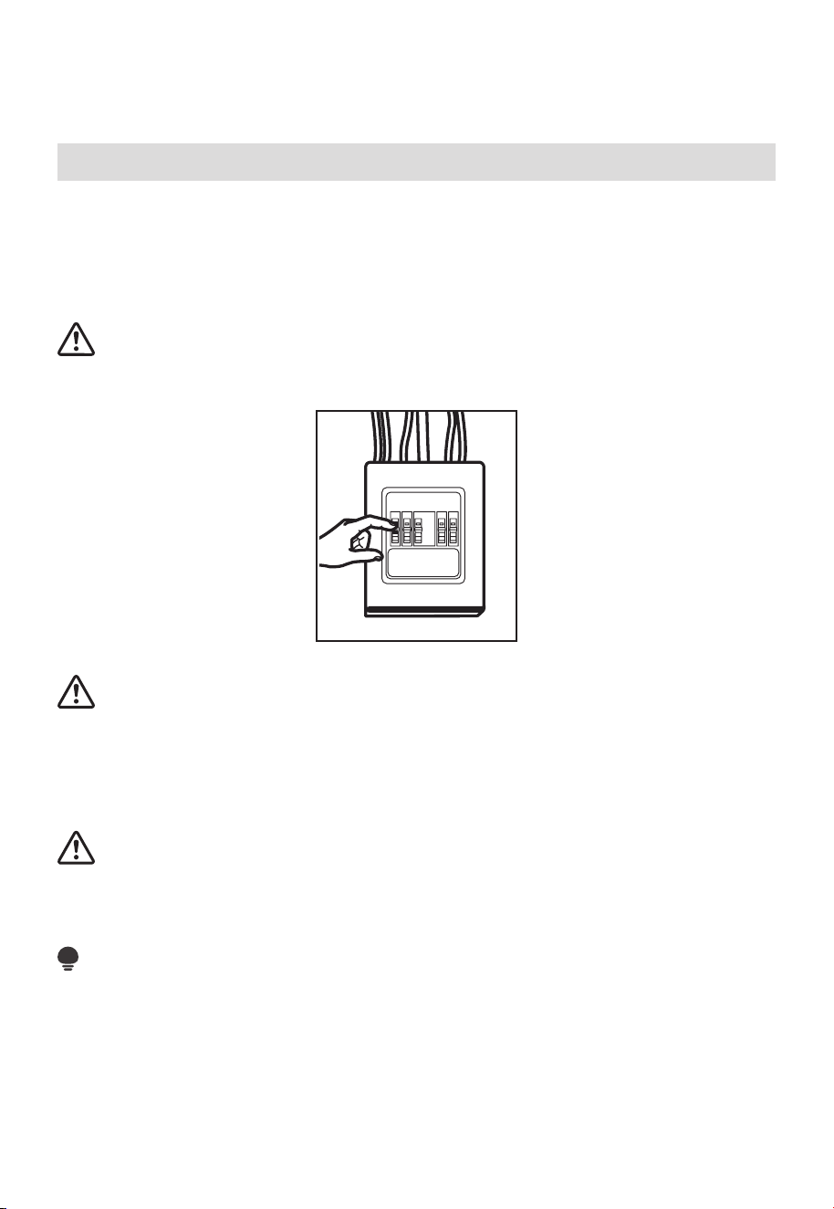
CAUTION:
For personal safety, remove house fuse or open circuit breaker before beginning
installation to avoid severe or fatal shock injury.
CAUTION:
For personal safety, the mounting surface must be capable of supporting the cabinet
load, in addition to the added weight of this 63–85 pound (28.5–38.5 kg) product, plus
additional oven loads of up to 50 pounds (22.7 kg) or a total weight of 113–135 pounds
(51.3–61.2 kg).
CAUTION:
For personal safety, this product cannot be installed in cabinet arrangements such as an
island or a peninsula. It must be mounted to BOTH a top cabinet AND a wall.
NOTE:
For easier installation and personal safety, it is recommended that two people install this
product.
IMPORTANT – PLEASE READ CAREFULLY. FOR PERSONAL SAFETY, THIS APPLIANCE
MUST BE PROPERLY GROUNDED TO AVOID SEVERE OR FATAL SHOCK.
EN-14
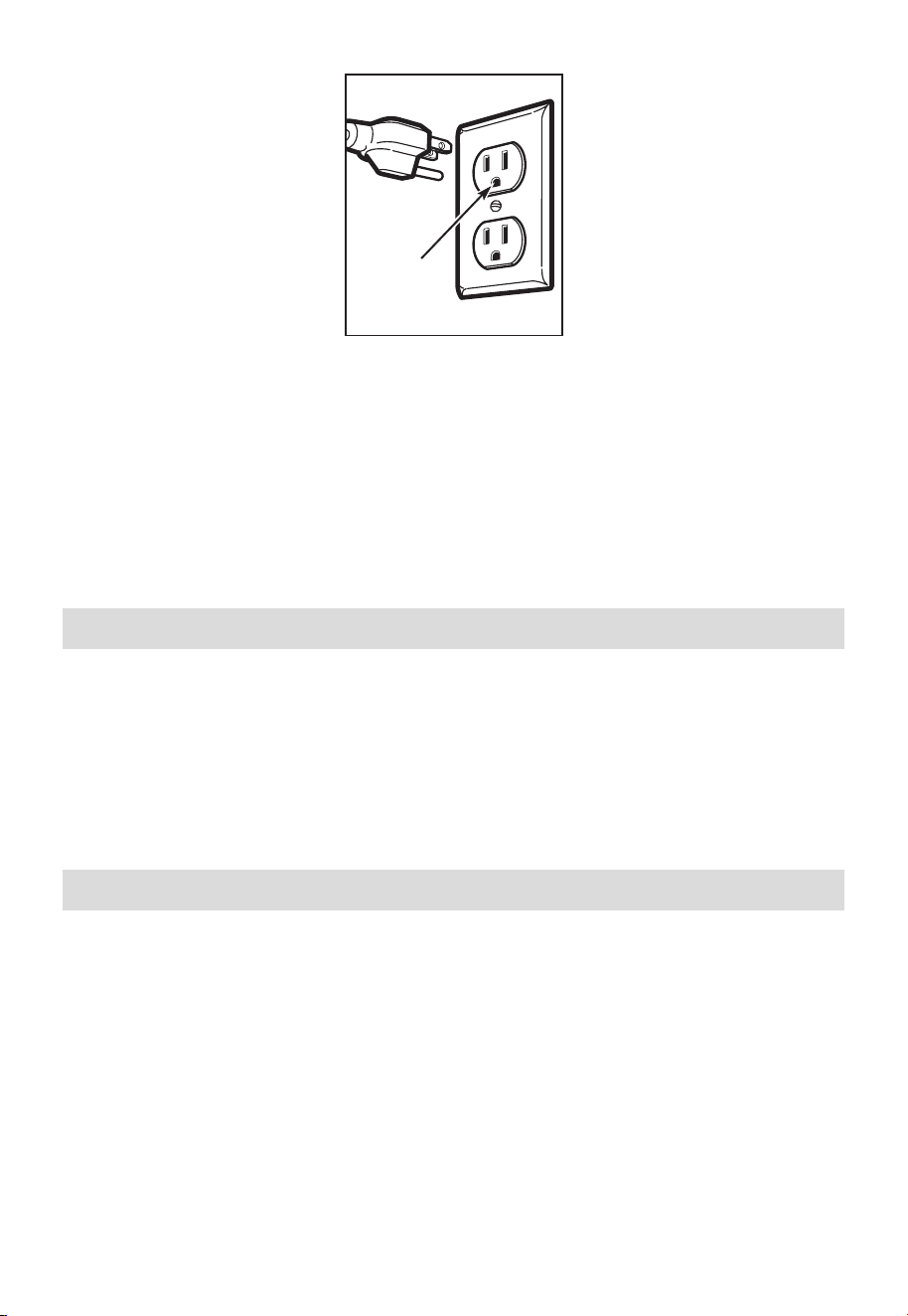
Ensure proper
ground exists
before use
The power cord of this appliance is equipped with a three-prong (grounding) plug
which mates with a standard three-prong (grounding) wall receptacle to minimize the
possibility of electric shock hazard from this appliance.
You should have the wall receptacle and circuit checked by a qualified electrician to make
sure the receptacle is properly grounded.
Where a standard two-prong wall receptacle is encountered, it is very important to have
it replaced with a properly grounded three-prong wall receptacle, installed by a qualified
electrician.
DO NOT, UNDER ANY CIRCUMSTANCES, CUT, DEFORM OR REMOVE ANY OF THE
PRONGS FROM THE POWER CORD. DO NOT USE WITH AN EXTENSION CORD.
Electrical Requirements
Product rating is 120V~ 60 Hz, 15 amps and 1.6 kilowatts. This product must be connected
to a seperate and dedicated supply circuit of the proper voltage and frequency. Wire size
must conform to the requirements of the National Electrical Code or the prevailing local
code for this kilowatt rating. The power supply cord and plug should be brought to a
seperate and dedicated 20 ampere branch circuit single grounded outlet. The outlet box
should be located in the cabinet above the microwave oven. The outler box and supply
circuit should be installed by a qualifed electrician and conform to the National Electrical
Code or the prevailing local code.
Damage—Shipment/Installation
1. If the unit is damaged in shipment, return the unit to the store in which it was bought
for repair or replacement.
2. If the unit is damaged by the customer, repair or replacement is the responsibility of
the customer.
3. If the unit is damaged by the installer (if other than the customer), repair or
replacement must be made by arrangement between customer and installer.

EN-15
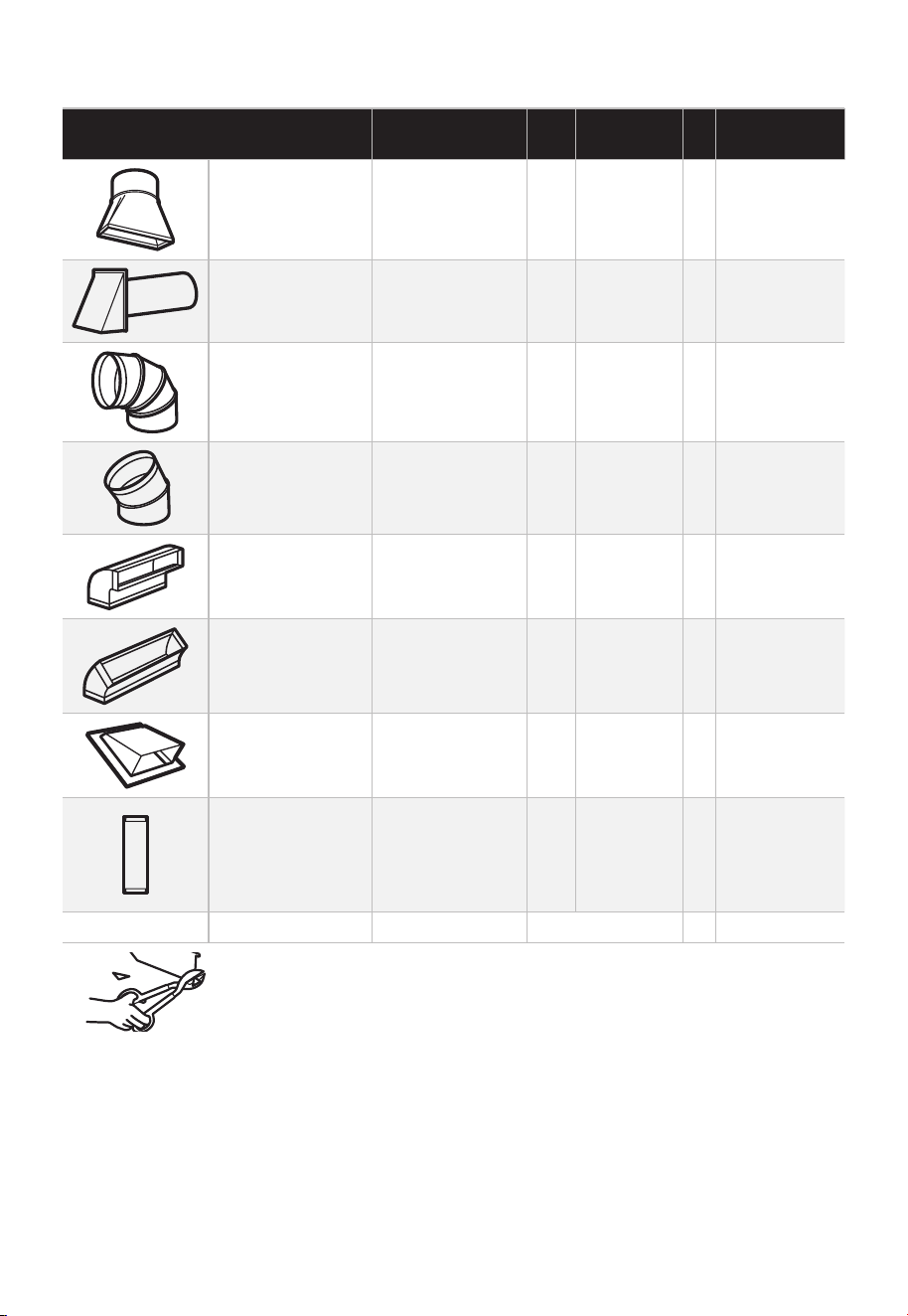
Parts Included
HARDWARE PACKET
PART QUANTITY
Wood Screws (
1
⁄
4
" x 2") 2
Toggle Bolts (and wing nuts) (
3
⁄
16
" x 3")
2
Self-Aligning Machine Screws
(
1
⁄
4
"-28 x 3
1
⁄
4
")
3
Nylon Grommet
(formetalcabinets)
1
You will find the installation hardware contained in a packet with the unit. Check to make
sure you have all these parts.
NOTE:
Some extra parts are included.
ADDITIONAL PARTS
PART QUANTITY
Top Cabinet Template 1
Rear Wall Template 1
USER
MANUAL
User Manual 1
Separately Packed Grease
Filters
2
Exhaust adaptor 1
EN-16
Glass Tray 1
Turntable Ring 1
For some models
Convection wire rack 1
For some models
Shelf 1
For some models
PureAir
®
Microwave Filter 1
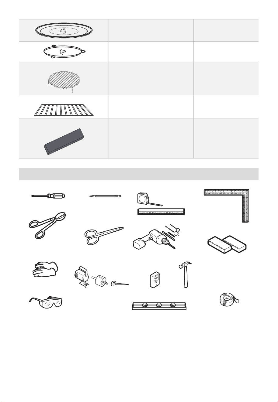
Tools You Will Need
# 1 Phillips screwdriver Pencil
Ruler or tape measure
and straight edge
Carpenter square
(optional)
Filler blocks or scrap
wood pieces, if needed
for top cabinet spacing
(used on recessed
bottom cabinet
installations only)
Electric drill with
3
⁄
16
“,
1
⁄
2
“
and
5
⁄
8
“ drill bits
Scissors
(to cut template,
ifnecessary)
Tin snips (for cutting
damper, if required)
Gloves
Saw (saber, hole or keyhole) Stud finder or Hammer (optional)
Duct and masking tape
Level
Safety goggles
EN-17
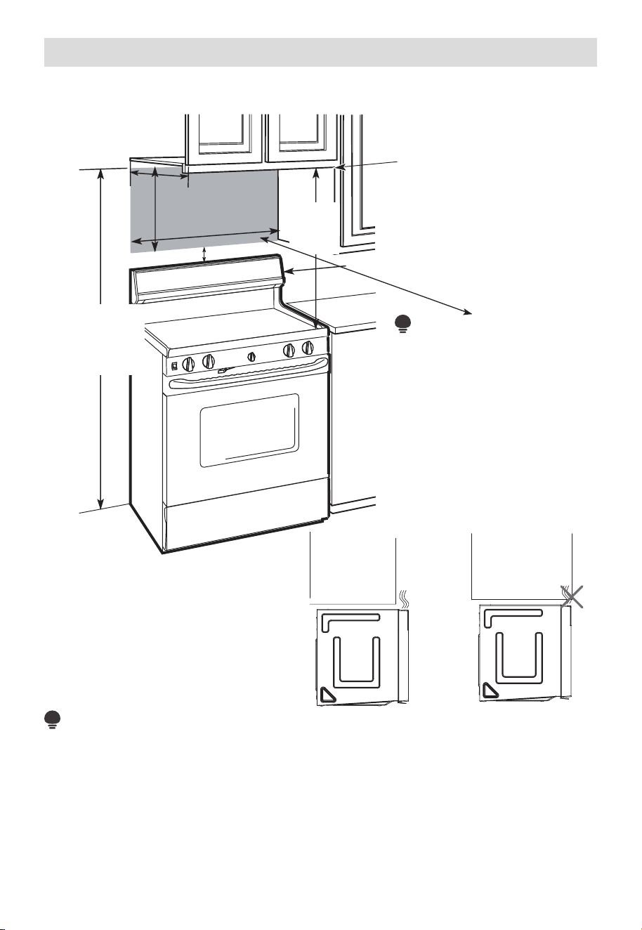
Mounting Space
MOUNTING SPACE
Bottom Edge of
Cabinet Needs to
be 30" (76.2 cm)
or More from the
Cooking Surface
66" (167.6 cm)
or More from the
Floor to the Top
of the Microwave
30"
(76.2cm)
min.
13" Maximum (33 cm)
30" (76.2 cm)
16
1
⁄
2
"
(41.9cm)
2" (5.1cm)
Backsplash
• If the cabinet depth
including the cabinet
doors is more than 13"
then the unit must be
spaced out from wall
using adequate materials
supporting 150 Ibs to
allow proper top vent air
exhaust/intake.
NOTE:
NOTE:
• The space between the cabinets must be 30" (76.2 cm) wide and free of obstructions.
• If you are going to vent your microwave oven to the outside, see Hood Exhaust Section
for exhaust duct preparation.
• When installing the microwave oven beneath smooth, flat cabinets, be careful to follow
the instructions on the top cabinet template for power cord clearance.
• As a guide to installation, see page 25 for Mounting Template Information.
EN-18
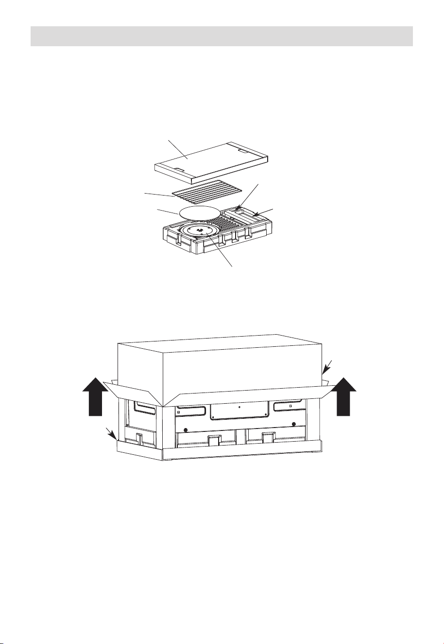
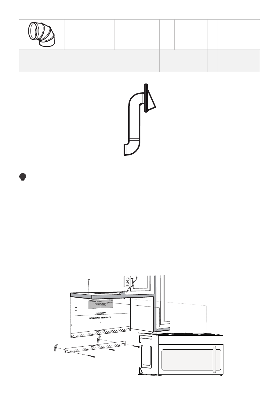
1. Placement Of The Mounting Plate
A. REMOVING THE MICROWAVE OVEN FROM THE CARTON/REMOVING THE
MOUNTING PLATE
1. Remove the top cover board, installation instructions, use and care, exhaust adapter,
turntable ring, shelf, filters, glass tray and the small hardwarebag. Do not remove the
Styrofoam protecting the front of the oven.
Top Cover Board
Shelf (For
some models)
EPE Pad
Filters and Turntable Ring below glass tray
Exhaust Adapter
Small Hardware Bag
2. Fold back all 4 carton flaps fully against carton sides. Then carefully roll the oven and
carton over onto the top side. The oven should be resting in the Styrofoam.
Styrofoam
Carton
3. Pull the carton up and off the oven.
EN-19
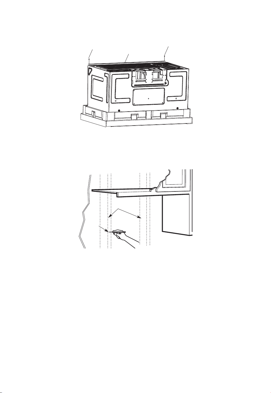
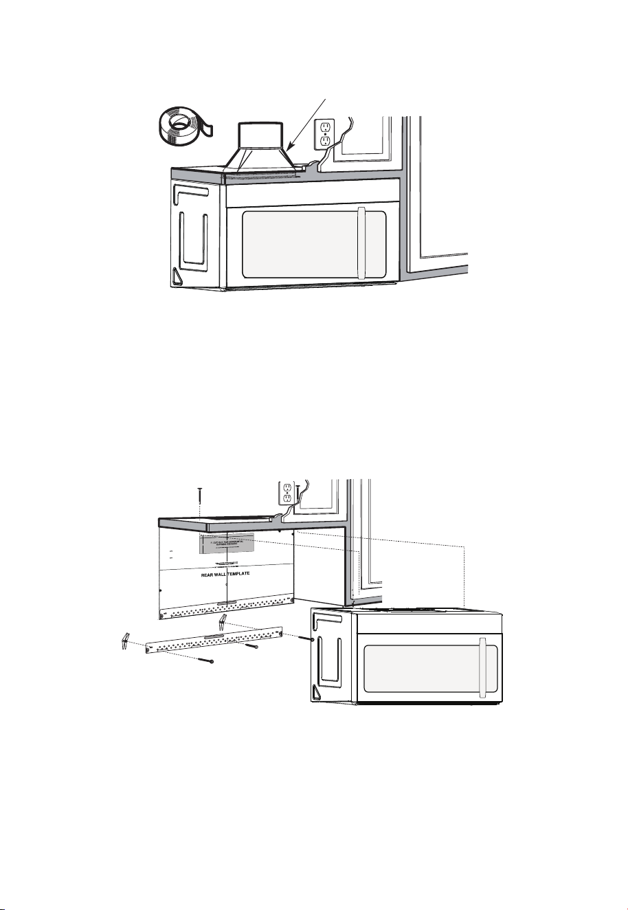
4. Cut the middle of the outer protective plastic bag to remove the mounting plate
Screws
Screws
Mounting Plate
5. Remove the screws from each end of the mounting plate. This plate will be used as
the rear wall template and for mounting. Reinstall the screws into the holes where they
were removed.
B. FINDING THE WALL STUDS
Wall Studs
Center
1. Find the studs, using one of the following methods:
-
Stud finder – a magnetic device which locates nails.
-
Use a hammer to tap lightly across the mounting surface to find a solid sound. This
will indicate a stud location.
2. After locating the stud(s), find the center by probing the wall with a small nail to find
the edges of the stud. Then place a mark halfway between the edges. The center of
any adjacent studs should be 16" (40.6 cm) or 24" (61 cm) from this mark.
3. Draw a line down the center of the studs.
THE MICROWAVE MUST BE CONNECTED TO AT LEAST ONE WALL STUD.
EN-20
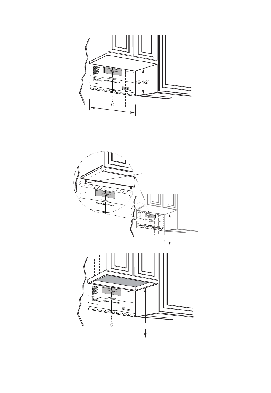
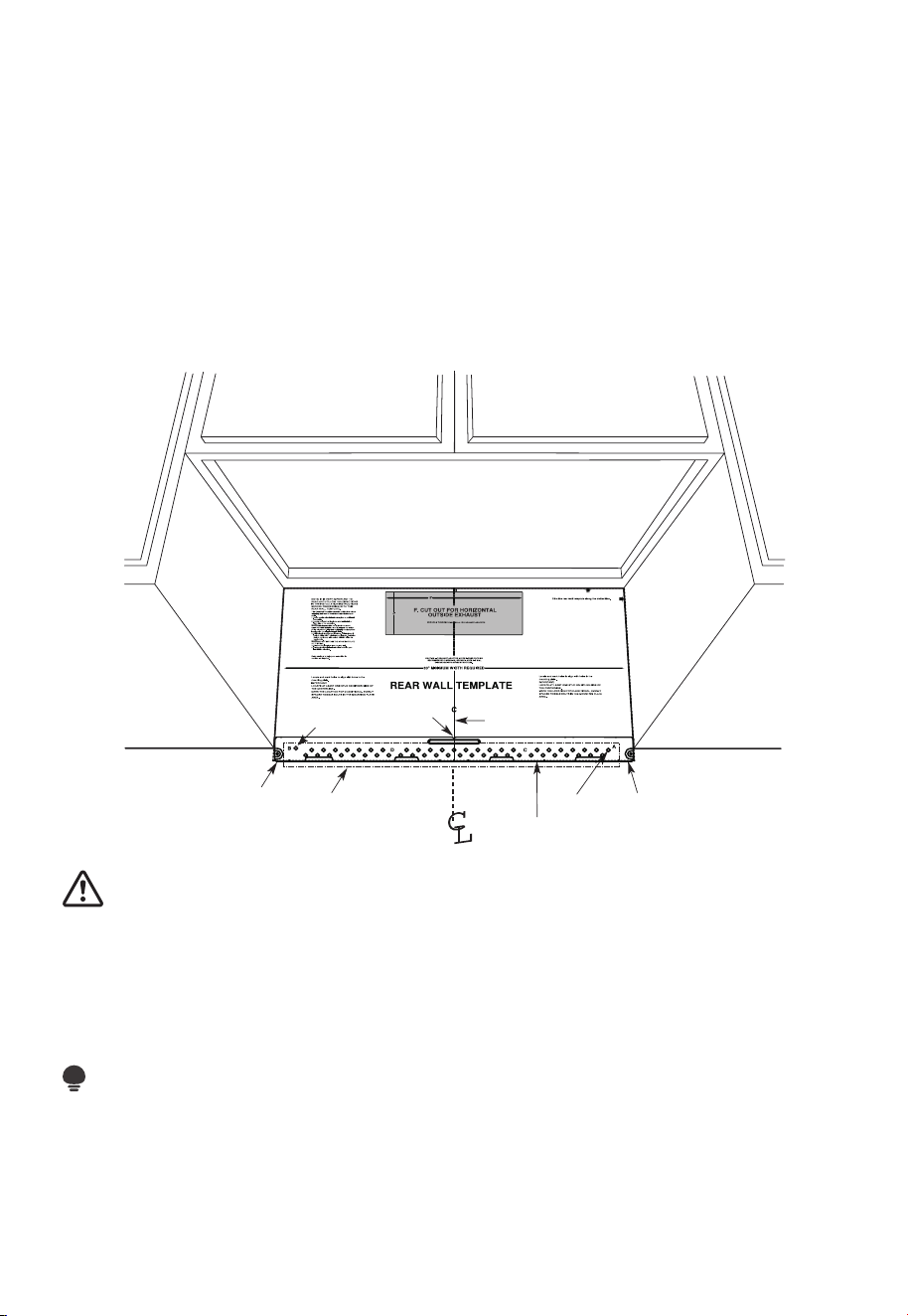
C. DETERMINING WALL PLATE LOCATION UNDER YOUR CABINET
Plate position-beneath flat bottom cabinet
At least 30"
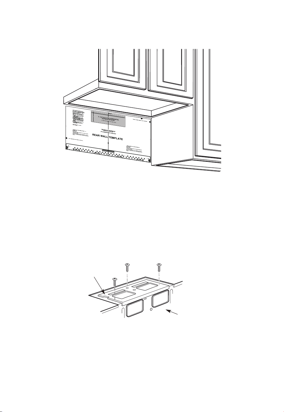
Draw a vertical line on the wall at the center of the 30" wide space.
Tape the Rear Wall Template onto the wall matching the centerline and touching the
bottom of the cabinet.
Plate position-beneath recessed bottom cabinet with front overhang
C
3/
8"
TO
EDGE
N
OT
E:
IT IS VERY IMP
O
RTA
NT
T
O
RE
AD
AND
FO
LL
O
W THE
D
IRE
C
T
I
ON
S
IN
T
H
E
IN
S
T
A
LL
ATI
ON
IN
ST
RUC
TIONS
B
E
F
ORE PR
OCEEDING WIT
H T
HIS
RE
AR W
A
LL
TEMPLATE.
This Re
a
r W
a
ll
Te
mplate
serv
e
s
t
o po
s
itio
n
t
he
bo
tt
om
m
o
u
nting p
la
t
e
a
nd
t
o
lo
ca
t
e
th
e
ho
ri
zo
nt
al
e
xh
au
st
ou
tle
t
.
1.
Use
a
le
ve
l
t
o
ch
eck
th
a
t
t
h
e
t
e
mp
la
te
is
posit
ione
d
a
c
c
u
ra
tely.
2
. Loc
ate
an
d
m
ar
k
at
lea
st
one stud
o
n t
he
le
ft or
ri
ght
sid
e
of the ce
n
te
r
lin
e
.
It
is
import
a
n
t
to use at
l
e
ast one wo
o
d
s
c
rew
mou
n
ted
f
ir
m
ly
in
a
stud
to
s
u
ppor
t the
weig
ht
of t
he
m
ic
r
owave.
M
ark
tw
o additiona
l,
eve
nly
spac
ed
lo
c
atio
ns for
the su
pplied
toggle
bolt
s
.
3.
Dril
l
holes
in
t
he
m
a
rk
e
d
locations.
Where
th
e
re
is
a
stud, drill
a
3
/
16" h
ole
fo
r
woo
d
s
c
rew
s
. F
or
h
o
le
s
th
at d
o
not li
n
e up
w
it
h
a
s
tud,
drill 5/
8
"
holes fo
r
toggle bolts.
DO
NOT INSTALL
T
H
E
MOUN
TIN
G
P
LA
T
E
AT
TH
IS
T
I
M
E
.
4
. R
e
mo
v
e
t
h
e templa
te
from t
he
r
e
ar
wall.
5
.
R
e
v
i
ew th
e
Inst
a
llatio
n
In
st
r
uction
boo
k
fo
r
y
ou
r
in
stalla
tio
n
si
t
uat
io
n
.
L
o
c
ate an
d
mark
ho
l
es
to
align w
ith h
o
les
i
n the
mo
u
n
t
in
g
p
l
ate.
I
MP
ORTANT
:
LO
CATE
AT LEAST ONE
S
TU
D ON EIT
H
ER
S
IDE OF
T
HE CE
NTER
LIN
E.
MA
RK
TH
E
LOCAT
I
ON
FO
R
2
A
DD
ITIONA
L, E
V
E
N
LY
S
P
AC
E
D TOGG
LE B
OL
T
S IN
THE MO
U
N
TIN
G
P
LAT
E
ARE
A.
Lo
cate a
n
d
ma
rk ho
les to
align with holes in
the
mo
unting p
l
a
te.
I
MPO
RTA
N
T:
LOCATE AT
L
E
AST
ONE ST
U
D ON
EI
TH
E
R SID
E
O
F
T
H
E CENTE
RLINE
.
MARK
THE LOCATION
FOR
2 AD
D
I
TI
ON
AL
,
E
V
E
NL
Y
SPACED
TO
GGLE B
OL
T
S IN
THE MO
U
NT
IN
G
PLATE
AR
E
A.
T
r
im
th
e
rea
r
wal
l
temp
late along th
e dotte
d line
.
Trim th
e rear
wa
l
l te
mpl
a
te
a
lo
n
g
th
e
dotted line
.
12"
4"
Da
r
le
vuelta
a
la
h
o
ja
p
a
ra
consu
l
ta
r la
v
ersió
n
en Espa
ño
l.
3/8
"
TO EDGE
N
O
TE
:
I
T
IS
VER
Y
IMPOR
T
AN
T T
O
R
EAD
AN
D
FO
L
LO
W
TH
E D
IR
EC
TI
O
N
S
I
N
T
H
E
I
N
ST
ALL
AT
IO
N
IN
ST
R
U
C
TI
O
N
S
B
EFO
R
E
PR
O
C
EED
IN
G
W
ITH
T
H
I
S
R
EAR
W
AL
L
T
EMPL
AT
E.
Th
is
R
e
a
r
W
a
ll
Te
mp
la
t
e s
er
v
e
s
to
p
o
s
it
i
o
n
th
e
b
o
t
to
m
mo
u
ntin
g
p
la
t
e
a
n
d
t
o l
o
c
at
e
th
e h
o
r
iz
on
ta
l e
x
h
a
us
t
ou
tle
t.
1
.
U
s
e
a
l
ev
e
l to
c
he
c
k
th
a
t
th
e
te
mp
la
t
e is
p
o
sitio
n
e
d
a
c
c
u
r
a
t
e
ly
.
2
.
L
o
c
a
te
a
n
d
ma
r
k
a
t le
a
s
t
o
n
e
s
t
u
d
o
n
t
he
le
ft
o
r
r
ig
ht
s
id
e
o
f
th
e c
e
n
te
r
l
in
e.
It
is
i
mp
o
r
ta
n
t t
o
u
s
e a
t le
a
s
t
o
n
e
w
o
o
d
s
c
r
e
w
mo
u
n
t
ed
f
ir
mly
in
a
s
tu
d
to
s
u
pp
o
r
t t
h
e
w
e
ig
h
t
o
f
th
e
mic
r
o
w
a
v
e
.
Ma
r
k
t
w
o
a
d
d
itio
na
l,
e
v
e
nl
y
s
p
a
ce
d
lo
c
a
tio
n
s
f
o
r
th
e
s
upp
li
e
d t
og
g
le
b
o
lts
.
3.
D
r
il
l h
ole
s
in
t
h
e
ma
r
k
e
d
lo
c
a
tio
n
s
.
W
h
e
r
e th
e
r
e
is
a
s
tu
d
, d
r
i
ll
a
3
/1
6"
h
o
le
fo
r
w
o
od
s
c
r
e
w
s
.
Fo
r
h
o
le
s
th
a
t d
o n
o
t lin
e
u
p
w
ith
a s
t
u
d
,
d
r
ill 5
/
8
" h
o
le
s fo
r
to
g
g
le
b
o
lts
.
D
O
N
O
T
IN
STA
L
L
TH
E
MO
U
N
TIN
G
P
L
ATE
AT TH
IS TIME
.
4
.
R
e
m
o
v
e
th
e
te
mp
la
te
fr
om
t
h
e
r
e
a
r
w
a
ll.
5
.
R
e
v
ie
w
t
he
In
s
ta
ll
atio
n
In
s
tru
c
t
io
n
bo
o
k fo
r
y
ou
r
in
sta
lla
tio
n
s
itu
a
tio
n.
Lo
cate an
d
ma
rk
h
ol
es t
o al
i
g
n w
it
h
h
ol
e
s
i
n t
h
e
mo
unti
n
g
pl
a
t
e
.
I
M
PO
R
T
AN
T
:
LOC
A
TE AT
LEAST
ONE ST
U
D
ON
EI
TH
ER
SI
D
E
OF
TH
E C
EN
TER
LIN
E.
MAR
K
T
H
E
LOC
ATIO
N
FO
R
2
AD
D
I
T
I
ON
AL
,
EVEN
L
Y
SPAC
ED
T
OG
GLE
BO
L
T
S
I
N
TH
E
MOUN
T
I
N
G
PLATE
AR
EA
.
Lo
cate
an
d
ma
rk
h
ol
es t
o al
i
g
n w
i
t
h
h
ol
e
s
in t
h
e
mo
un
tin
g pl
a
t
e
.
IMPO
R
T
AN
T:
LOC
AT
E AT
LEAS
T
ON
E ST
U
D
ON
EI
T
H
ER
SID
E
O
F
TH
E
C
EN
TE
R
LIN
E
.
MAR
K
T
H
E
LO
C
ATIO
N
F
O
R
2
AD
D
I
TI
ON
AL
, EVEN
L
Y
SPA
C
E
D
T
O
G
GLE
BO
L
T
S
I
N
TH
E
MO
U
N
TI
N
G
P
LAT
AR
EA.
Trim
th
e
r
e
ar
wall
t
em
p
lat
e
a
l
ong
th
e
d
otted
l
i
ne.
Trim
th
e
r
ear
wal
l
tem
pl
ate
a
l
ong
th
e
dotted
li
ne.
12
"
4"
D
arle
v
u
el
t
a
a
la
h
o
ja
p
a
r
a
c
o
n
s
u
lt
a
r
la
v
e
r
si
ó
n
e
n
E
s
p
añ
o
l.
Draw a line on the back
wall equal to the depth
of the front overhang.
30" to Cooktop
Plate position-beneath framed recessed cabinet bottom
30" to Cooktop
Draw a vertical line on the wall at the center of the 30" space.
Tape the Rear Wall Template onto the wall matching the centerline and touching the
bottom cabinet frame.
EN-21
Your cabinets may have decorative trim that interferes with the microwave installation.
Remove the decorative trim to install the microwave properly and to make it level.
THE MICROWAVE MUST BE LEVEL.
Use a level to make sure the cabinet bottom is level.
If the cabinets have a front overhang only, with no back or side frame, install the
mounting plate down the same distance as the front overhang depth. This will keep the
microwave level.
1. Measure the inside depth of the front overhang.
2. Draw a horizontal line on the back wall an equal distance below the cabinet bottom as
the inside depth of the front overhang.
3. For this type of installation with front overhang only, align the mounting tabs with this
horizontal line, not touching the cabinet bottom as described in Step D.
D. ALIGNING THE WALL PLATE
3/8" TO EDGE
Horizontal Line
Area E
Draw a horizontal line on wall at the
bottom of “Rear Wall Template”.
Horizontal LineHole A
Hole B
Centerline
notches
Draw a Vertical Line
on Wall from Center
of Top Cabinet
CAUTION:
Wear gloves to avoid cutting fingers on sharp edges.
1. Draw a vertical line on the wall at the center of the 30" wide space.
2. Draw a horizontal line on the wall at the bottom of "Rear Wall Template".
3. Find a wall stud in area "E" of mounting plate Refer to section 1B. Finding the wall
studs.
4. For attaching the mounting plate into stud drill a 3/16" hole into wood stud. Drill a
5/8" hole for toggle bolt in 1 other location (Hole A or Hole B)
NOTE:
DO NOT MOUNT THE PLATE AT THIS TIME.
EN-22
NOTE:
Holes A and B are inside area E. If neither of Holes A and B are not in a stud, find a stud
somewhere in area E and draw a circle to line up with the stud. It is important to have at
least one wood screw mounted firmly in a stud to support the weight of the microwave.
Set the mounting plate aside.
2. Installation Types (Choose A, B or C)
This microwave oven is designed for adaptation to the following three types of
ventilation:
A. Outside Top Exhaust (Vertical Duct)
B. Outside Back Exhaust (Horizontal Duct)
C. Recirculating (Non-Vented Ductless)
NOTE:
This microwave is shipped assembled for Recirculating. Select the type of ventilation
required for your installation and proceed to that section.
A. OUTSIDE TOP EXHAUST (VERTICAL DUCT)
Adaptor in Place for
Outside Top Exhaust
See page 26
B. OUTSIDE BACK EXHAUST (HORIZONTAL DUCT)
See page 33
Adaptor Must Be
Moved to the Back for
Outside Back Exhaust
EN-23
C. RECIRCULATING (NON-VENTED DUCTLESS)
See page 41
Models are shipped for recirculating exhaust. Some models have a disposable charcoal
filter installed to help remove smoke and odors.
NOTE:
Read the next two pages only if you plan to vent your exhaust to the outside. If you plan
to recirculate the air back into the room, proceed to page 23-26.
Installation Instructions For External Exhaust Ducting
NOTE:
If you need to install ducts, note that the total duct length of 3
1
⁄
4
" x 10" (8.2 x 25.4 cm)
rectangular or 5" (12.7 cm) diameter/6" ” (15.2 cm) diameter round duct should not
exceed 120 equivalent feet (36.5 m).
Outside ventilation requires an EXTERNAL EXHAUST DUCT. Read the following carefully.
NOTE:
It is important that venting be installed using the most direct route and with as few
elbows as possible. This ensures clear venting of exhaust and helps prevent blockages.
Also, make sure dampers swing freely and nothing is blocking the ducts.
Exhaust connection:
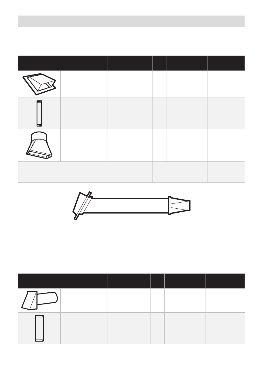
The exhaust adaptor has been designed to mate with a standard 3
1
⁄
4
" x 10” (8.2 x 25.4
cm) rectangular duct.
If a round duct is required, a rectangular-to-round transition adaptor must be used. A5"
(12.7cm)/6" (15.2cm) diameter duct is acceptable to use.
Maximum duct length:
For satisfactory air movement, the total duct length of 3
1
⁄
4
" x 10" (8.2 x 25.4 cm)
rectangular or 5" (12.7 cm) diameter/6" (15.2 cm) diameter round duct should not
exceed 120 equivalent feet (36.5 m).
Elbows, transitions, wall and roof caps, etc., present additional resistance to airflow and
are equivalent to a section of straight duct which is longer than their actual physical size.
When calculating the total duct length, add the equivalent lengths of all transitions and
adaptors plus the length of all straight duct sections. The chart below shows you how
to calculate total equivalent ductwork length using the approximate feet of equivalent
EN-24
length of some typical ducts.
DUCT PIECES
EQUIVALENT
LENGTH
x
NUMBER
USED
=
EQUIVALENT
LENGTH
Rectangular-to-
Round Transition
Adaptor*
5 Ft. (1.5 m) x ( ) = Ft. or m
Wall Cap 40 Ft. (12.2 m) x ( ) = Ft. or m
90° Elbow 10 Ft. (3 m) x ( ) = Ft. or m
45° Elbow 5 Ft. (1.5 m) x ( ) = Ft. or m
90° Elbow 25 Ft. (7.6 m) x ( ) = Ft. or m
45° Elbow 5 Ft. (1.5 m) x ( ) = Ft. or m
Roof Cap 24 Ft. (7.3 m) x ( ) = Ft. or m
Straight Duct 6"
(15.2 cm) Round
or 3
1
⁄
4
" x 10"
(8.2 x 25.4 cm
Rectangular)
1 Ft. (0.3 m) x ( ) = Ft. or m
Total Ductwork = Ft. or m
* IMPORTANT: If a rectangular-to-round transition adaptor is used,
the bottom corners of the damper will have to be cut to fit, using
the tin snips, in order to allow free movement of the damper.
Equivalent lengths of duct pieces are based on actual tests and reflect requirements for
good venting performance with any vent hood.
EN-25
External Exhaust Ducting
OUTSIDE TOP EXHAUST (EXAMPLE ONLY)
The following chart describes an example of one possible ductwork installation.
DUCT PIECES
EQUIVALENT
LENGTH
x
NUMBER
USED
=
EQUIVALENT
LENGTH
Roof Cap 24 Ft. (7.3 m) x (1) = 24 Ft. (7.3 m)
12 Ft. (3.6 m)
Straight Duct
(6"/15.2 cm
Round)
12 Ft. (3.6 m) x (1) = 12 Ft. (3.6 m)
Rectangular-to-
Round Transition
Adaptor*
5 Ft. (1.5 m) x (1) = 5 Ft. (1.5 m)
Equivalent lengths of duct pieces are based on
actual tests and reflect requirements for good
venting performance with any vent hood.
Total Length = 41 Ft. (12.5 m)
* IMPORTANT: If a rectangular-to-round transition adaptor is used, the bottom corners of
the damper will have to be cut to fit, using the tin snips, in order to allow free movement
of the damper.
OUTSIDE BACK EXHAUST (EXAMPLE ONLY)
The following chart describes an example of one possible ductwork installation.
DUCT PIECES
EQUIVALENT
LENGTH
x
NUMBER
USED
=
EQUIVALENT
LENGTH
Wall Cap 40 Ft. (12.2 m) x (1) = 40 Ft. (12.2 m)
3 Ft. Straight
Duct (3
1
⁄
4
"x
10"/8.2 x 25.4 cm
Rectangular)
3 Ft. (0.9 m) x (1) = 3 Ft. (0.9 m)
EN-26
90° Elbow 10 Ft. (3 m) x (2) = 20 Ft. (3 m)
Equivalent lengths of duct pieces are based on
actual tests and reflect requirements for good
venting performance with any vent hood.
Total Length = 63 Ft. (19.2 m)
NOTE:
For back exhaust, care should be taken to align exhaust with space between studs, or
wall should be prepared at the time it is constructed by leaving enough space between
the wall studs to accommodate exhaust.
A. OUTSIDE TOP EXHAUST (Vertical Duct)
INSTALLATION OVERVIEW
A1. Attach Mounting Plate to wall
A2. Prepare Top Cabinet
A3. Configure Microwave Blower for Outside/Top Exhaust
A4. Check Damper Operation
A5. Mount Microwave Oven
A6. Adjust Exhaust Adapter
A7. Connect Duct-work
12"
4"
NOTE:
READ AND F
O
I
T
I
S
V
ERY
LLO
I
W
MPO
T
HE
R
D
TANT T
O
IRECTIO
IN THE INSTALLATI
ON
INSTRU
CTIO
N
N
S
S
BE
F
O
RE
PRO
H
T
H
TI W G N I D E E
C
IS
REAR
W
ALL
TEM
PL
A
TE
.
ll Templ
a
te s
erv
es t
o
p
1
ou
a
. Us
mo
u
tl
e
t.
ntin
e
a l
T
hi
s
Rea
g
p
rW
l
a
a
t
e
a
nd
to
lo
ca
te
th
e
h
ori
z
o
s
o
n
itio
ta
n
l e
t
h
xh
e b
au
o
st
t
t
o
m
ionedto check
tha
t
th
e
t
e
mplate
s
o
p si
it
pl
ar
k hol
es
to a
li
gn with holes
in the
L
oca
t
mounting
RTANT
e and m
:
ate
.
IMPO
E
AT LEA
THE CENT
HE LO
CATIO
L
OC
AT
E
RL
INE
ST
.
O
NE STUD ON EI F O
E D I SRE H
T
SP
AC
E
AREA.
MAR
K
T
D TO
GGLE
BO
NF
LT
S
O
IN
R 2 ADD
IT
THE MO
IO
UN
NA
TING
L, EVENL
PLA
TE
Y
Trim the r
e
ar wal
l template a
long
the
dott
ed
l
ine.
k
h
ole
s to
a
l
i g
n with h
ole
s
in t
he
m
ounting
L
oca
te a
n
d
mar
O
RT
AN
T
plate.
:IMP
AT LEA
THE
CENT
HE
L
OCATIO
SP
LOCATE
ER
L
I
NE.
I E N
O
D
U T
S E
N O
TS THER SI
D
E OF
AR
EA.
MARK
ACED
T
T
OG
G
LE B
O
N
FO
LTS IN
R 2
ADDITION
THE
MO
UN
A
T
ING
L,
EV
ENL
PLATE
Y
Trim the rear
w
a
l
l te
m
plate along
t
he do
tt
ed
lin
e.
3/8"
TOEDGE
2. L
o
c
c
cu
a
te
r
a
e
a
tely
v
nd
el
.
m
a
r
k a
t leas
t
o
d
u
ts
e
n
o
n
th r
o
t
f
e
l
e
igh
t
si
d
e of
t
he cente
rl
eni
.
r
It is im
p
o
rta
nt to
u
s
e
at l
e
ts
a one
wood
sc
rew
mo
ro
unte
d
wa
v
fi
e.
r
M
ml
y
ar
i
k
n
t
a
w
s
o
a
tud
d
di
t
i
to
s
up
p
ona
l,
ev
or
en
t
the
w
ly
s
e
pa
ight
ced
e mic
f
e
o
r
s
i
n
t
he
th
s
e
u
m
ppl
ar
k
ied to
ed
l
o
g
c
g
le bo
l
ation
t
s
s
.
.
Wh
ere t
her
e is
lo
o
f
a
c
th
3. Dr
a
th
s
i
tio
at
ll
tu
n
h
d
s
ol
d
ri
l
l a
3/1
6"
h
ole for
w
oo
d
sc
r
e
w
s
.
F
o
r
h
o
l
es
do
,
h t i
w
p
u
e
a
stud, dri
l
l
5/8
" h
oles
fo
r
e bo
n
o
lts
t
li
n
.
NO
T
t
oggl
IN
STAL
L
T
HE
MO
U
N
TI
NG
P
L
ATE
AT
4.
R
e
T
m
HI
S
T
D
O
th
IME.
e te
o
v
e
mp
l
a
te fr
omth
e r
ea
r
wall
.
5.Re
v
ie
w
the I
n
stall
a
t s n I n
o i
t ruc
t
i
on bo
o
k for you
r
instal
l
a
t
io
n s
it
ua
tio
n
.
Dar
le
vu
el
t
a
ala
hojapa
raco
ns
ul
t
ar
la
v
e
r
si
ón
en
Espa
ño
l.
EN-27
IMPORTANT NOTES:
1. Make sure the screws for the Blower Motor and Blower Plate are securely tight-ened
when they are installed. This will help to prevent excessive vibration.
2. Make sure the Motor wiring has been properly routed and secured, and that the wires
are not pinched.
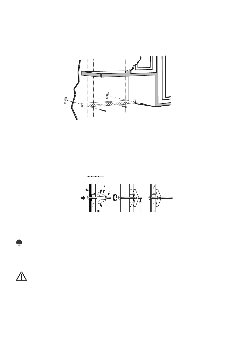
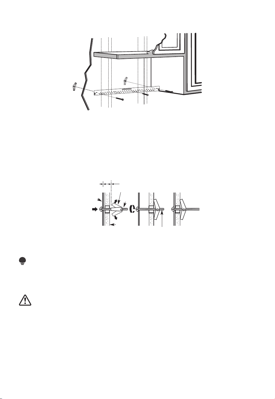
A1. ATTACH THE MOUNTING PLATE TO THE WALL
• Attach the plate to the wall using toggle bolts.
• At least one wood screw must be used to attach the plate to a wall stud.
1. Remove the toggle wings from the bolts
2. Insert the bolts into the mounting plate through the holes designated to go into
drywall and reattach the toggle wings to 3/4" (19mm) onto each bolt.
To use toggle bolts:
Spacing for Toggles
More Than Wall
Thickness
Toggle Wings
Toggle
Bolt
Bolt End
Wall
Mounting
Plate
3. Place the mounting plate against the wall and insert the toggle wings into the holes in
the wall to mount the plate.
NOTE:
Before tightening toggle bolts and wood screw, make sure the bottom of the mounting
plate touches the bottom of the cabinet when pushed flush against the wall and the plate
is properly centered under the cabinet.
CAUTION:
Be careful and avoid pinching fingers between the back of the mounting plate and the
wall.
4. Tighten all bolts. Pull the plate away from the wall to help tighten the bolts.
EN-28
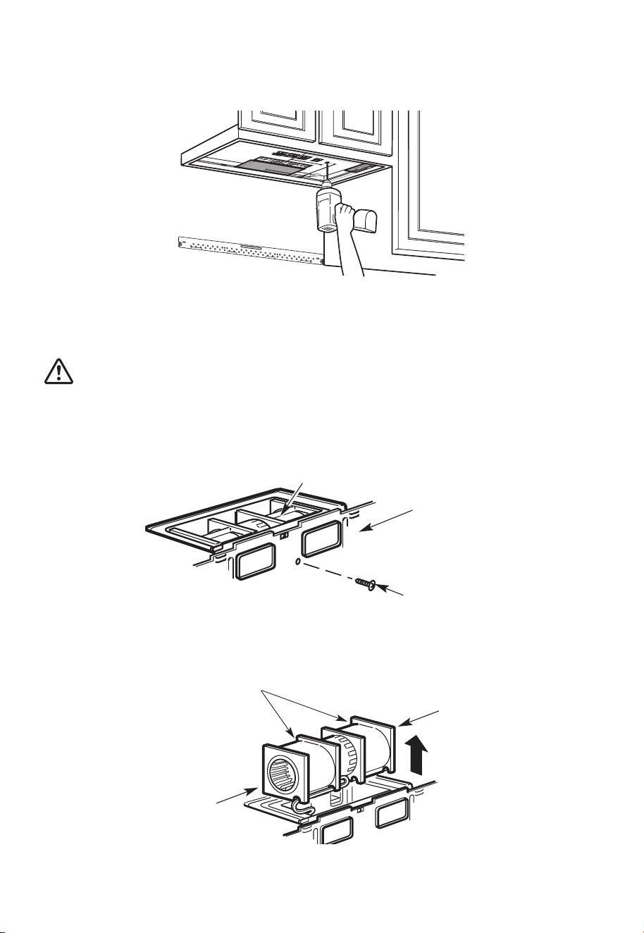
A2. USE TOP CABINET TEMPLATE FOR PREPARATION OF TOP CABINET
You need to drill holes for the top support screws, a hole large enough for the power
cord to fit through, and a cutout large enough for the exhaust adaptor.
1. Read the instructions on the TOP CABINET TEMPLATE.
2. Tape it underneath the top cabinet.
3. Drill the holes, following the instructions on the TOP CABINET TEMPLATE.
CAUTION:
Wear safety goggles when drilling holes in the cabinet bottom.
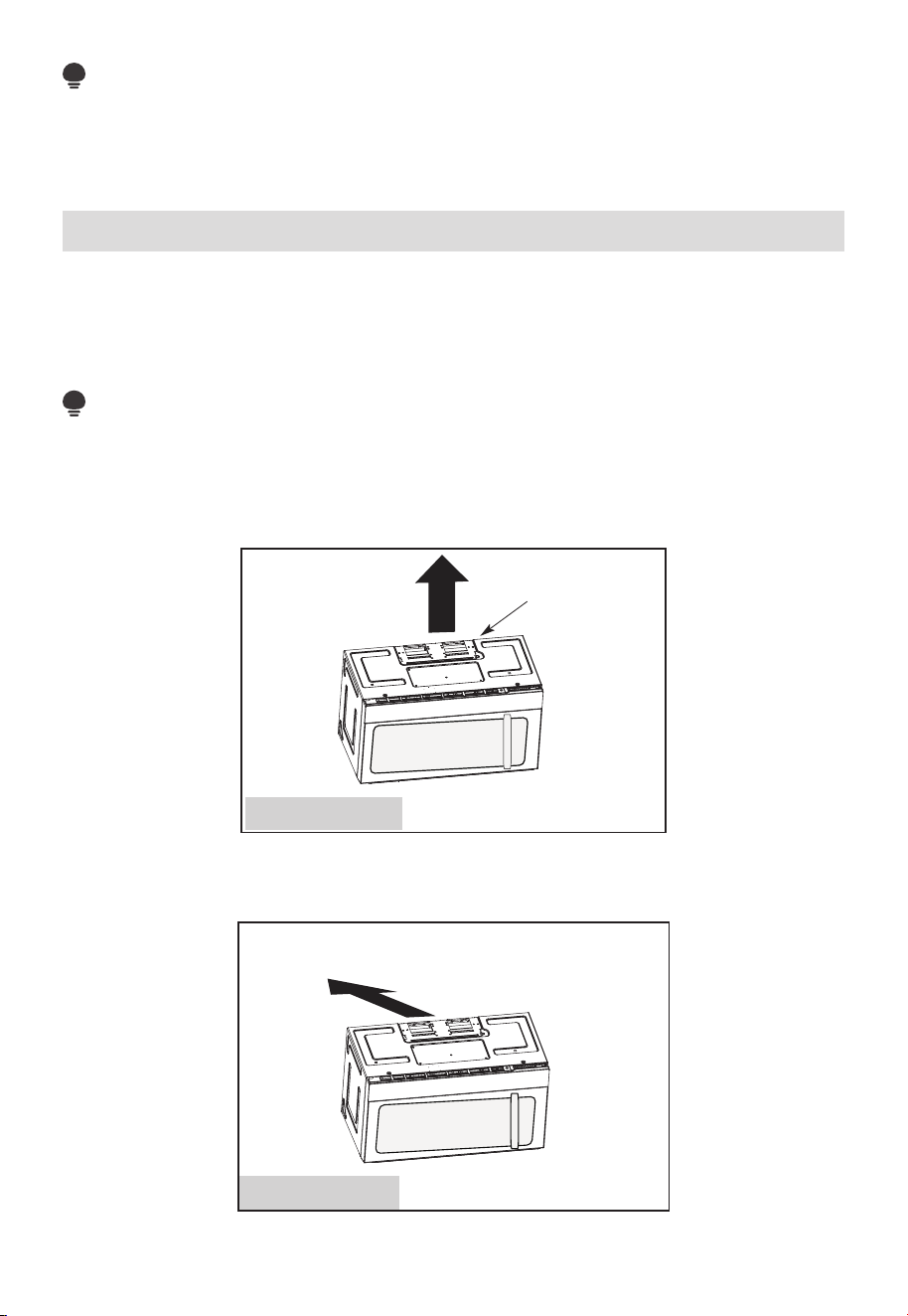
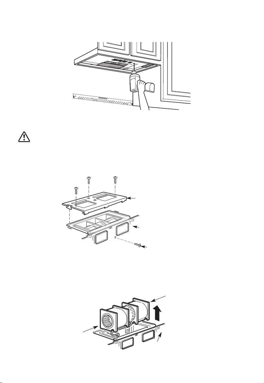
A3. ADAPTING MICROWAVE BLOWER FOR OUTSIDE TOP EXHAUST
1. Place the microwave in its upright position, with the top of the unit facing up.
Blower Plate
Back of Microwave
Blower Motor Screw
Remove the screw that holds the blower plate to the microwave. Remove and save the
screw holding the blower motor to the microwave.
2. Carefully pull out the blower unit. The wires will extend far enough to allow you to
adjust the blower unit.
End B
Back of
Microwave
End A
EN-29
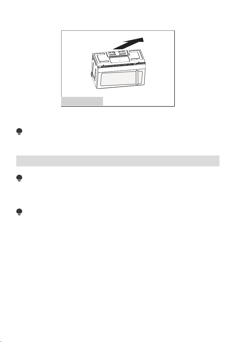
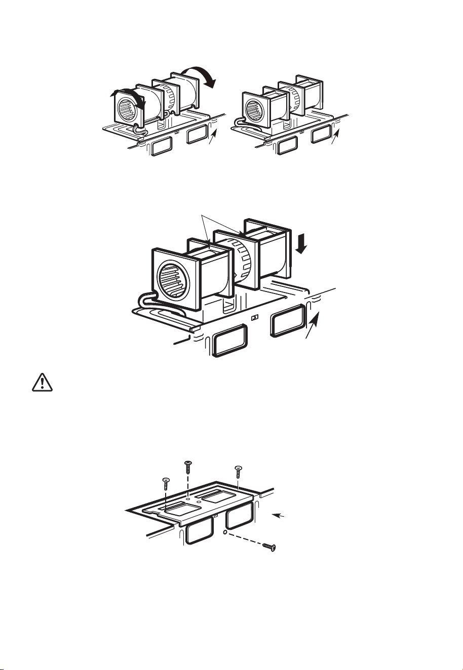
3. Roll the blower unit 90° so that fan blade openings are facing out the top of the
microwave.
Before Rotation After Rotation
Back of
Microwave
Back of
Microwave
4. Place the blower unit back into the opening.
AFTER: Fan Blade
Openings Facing Top
Back of
Microwave
CAUTION:
Do not pull or stretch the blower unit wiring. Make sure the wires are not pinched, and
that they are properly secured.
5. Secure blower unit to microwave with the screw removed in Step 1. Make sure the
screw is tight.
6. Replace blower plate with the screw removed in Step 1. Make sure the screw is tight.
Back of
Microwave
EN-30
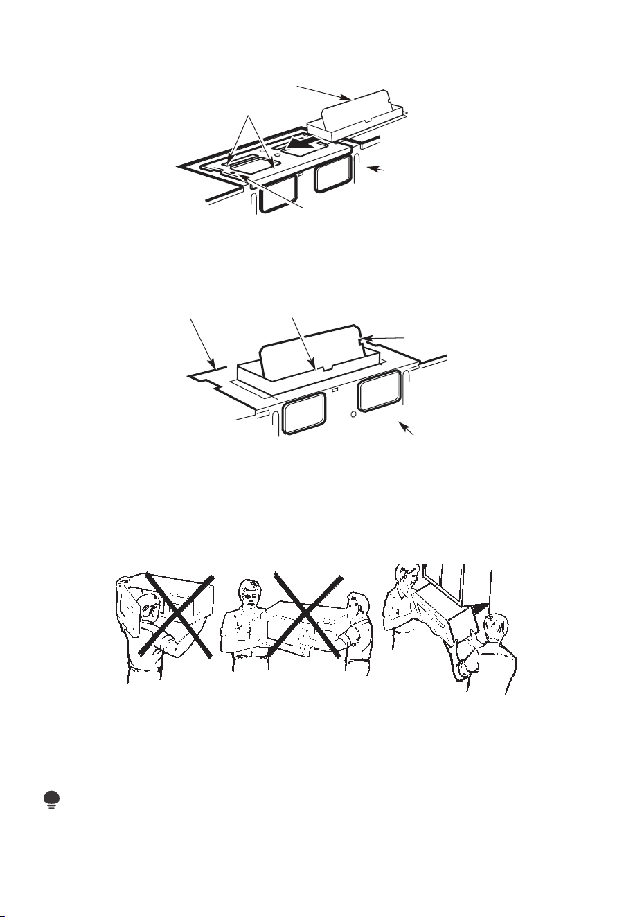
7. Attach the exhaust adaptor to the top of the blower plate by sliding it into the guides
of the blower plate.
Adaptor
Guide
Back of
Microwave
Locking Tab
Push in securely until it is in the locking tabs. Take care to assure that the damper hinge
is installed so that the damper swings freely.
A4. CHECK FOR PROPER DAMPER OPERATION
Back of
Microwave
Damper
Exhaust
Adaptor
Blower Plate
• Make sure tape securing damper is removed and damper pivots easily before mounting
microwave.
• You will need to make adjustments to assure proper alignment with your house exhaust
duct after the microwave is installed.
A5. MOUNT THE MICROWAVE OVEN
FOR EASIER INSTALLATION AND PERSONAL SAFETY, WE RECOMMEND THAT TWO
PEOPLE INSTALL THIS MICROWAVE OVEN.
IMPORTANT: Do not grip or use the handle or heat shield during installation. Do not
remove the cardboard spacers between the heat shield and door.
NOTE:
If your cabinet is metal, use the nylon grommet around the power cord hole to prevent
cutting of the cord.
EN-31
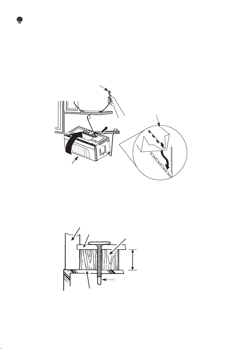
NOTE:
We recommend using filler blocks if the cabinet front hangs below the cabinet bottom
shelf.
IMPORTANT: If filler blocks are not used, case damage may occur from overtightening
screws.
NOTE: When mounting the
microwave oven, thread
power cord through hole
in bottom of top cabinet.
Keep it tight throughout
steps 1-3. Do not pinch
cord or lift oven by pulling
cord.
1. Lift microwave, tilt it
forward, and hook slots
at back bottom edge
onto four lower tabs of
mounting plate.
2 Rotate front of oven up
against cabinet bottom.
3. Insert a self-aligning screw through top center cabinet hole. Temporarily secure the
oven by turning the screw at least two full turns after the threads have engaged. (It
will be completely tightened later.) Be sure to keep power cord tight. Be careful not to
pinch the cord, especially when mounting flush to bottom of cabinet.
Cabinet Front
Cabinet Bottom Shelf
Filler Block
Equivalent to Depth
of Cabinet Recess
Self-Aligning Screw
Microwave Oven Top
4. Attach the microwave oven to the top cabinet.
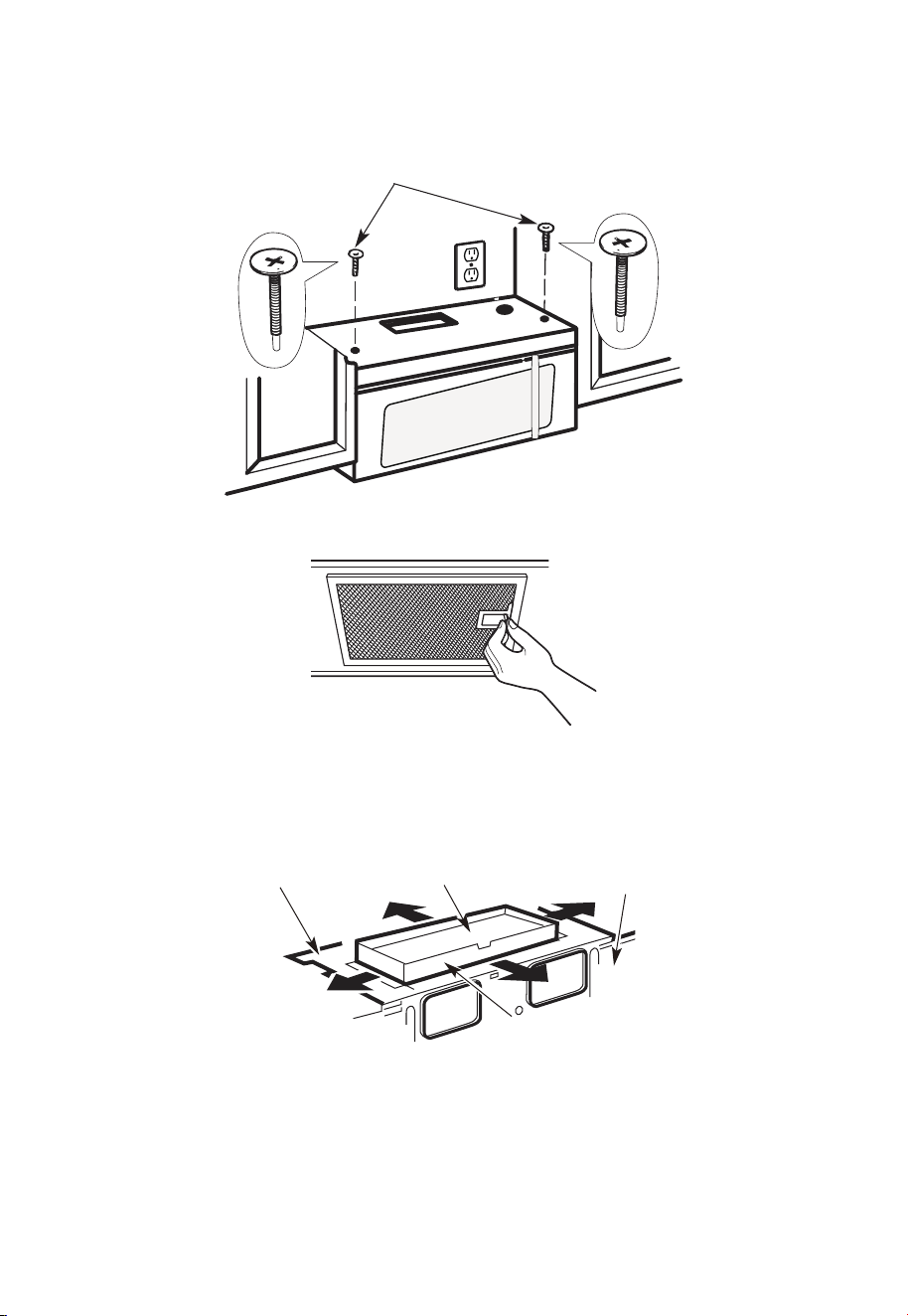
EN-32
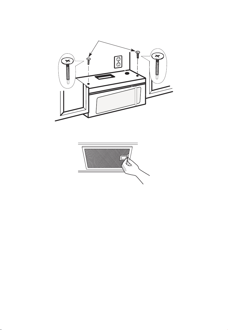
5. Insert 2 self-aligning
screws through outer
top cabinet holes. Turn
two full turns on each
screw.
6. Tighten the outer two screws to the top of the microwave oven. (While tightening
screws, hold the microwave oven in place against the wall and the top cabinet.)
7. Install grease filters. See the Use & Care Guide packed with the microwave.
A6. ADJUST THE EXHAUST ADAPTOR
Open the top cabinet and adjust the exhaust adapter to connect to the house duct.
Blower Plate
Damper
Back of
Microwave
For Front-to-Back or
Side-to-Side Adjustment,
Slide the Exhaust Adapter
as Needed
EN-33
A7. CONNECTING DUCTWORK
House Duct
1. Extend the house duct down to connect to the exhaust adapter.
2. Seal exhaust duct joints using furnace duct tape for high temperature applications
B. OUTSIDE BACK EXHAUST (Horizontal Duct)
INSTALLATION OVERVIEW
B1. Prepare Rear Wall
B2. Remove Blower Plate
B3. Attach Mounting Plate to Wall
B4. Prepare Top Cabinet
B5. Adjust Blower
B6. Mount the Microwave Oven
12"
4"
NOTE
:
REA
D AND FO
I
T
I
S
V
ERY
LLO
I
W
MPO
T
HE
R
D
TANT
T
O
IRECTIO
IN THE INSTALLAT
I
ON I
NSTRU
CTI
O
N
N
S
S
B
EF
O
RE PR
O
H
T
H T I
W
G N
I
D E
E
C IS
REAR WA
L
L TEM
PL
ATE
.
ll Te
mpl
a
te
serv
es
to p
1
ou
a
. Us
mou
tle
t.
ntin
e
a l
T
h
is
R
ea
g
p
rW
l
a
a
t
e
and
to
loca
te
th
e h
or
iz
o
s
o
n
itio
t
a
n
l e
t
h
xh
e b
au
o
st
t
t
o
m
ioned
to
chec
k tha
t
th
e
t
e
m
pl
at
e
is
p
osit
pl
ark
holes
to
ali
gn wi
th holes
i
n t
he
L
ocat
mounting
RTANT
e and m
:
ate
.
IMPO
E
AT LEA
THE CENT
HE LOCATIO
L
O
C
AT
ERL
INE
ST
.
ONE STUD
ON EI
F
O
ED I S R
E H
T
SP
AC
E
AREA.
MAR
KT
D T
OGGLE
BO
NF
LT
S
O
I
N
R 2 ADD
IT
THE MO
IO
UN
NA
T
ING
L, EV
EN
L
P
LATE
Y
Trim the
re
ar wal
l tem
plat
e along
the
dott
e
d l
ine.
k
h
ole
s to g
ila n w
ith holes
in t
he
moun
tin
g
Loca
te a
n
d
mar
O
RTAN
T
plate.
:IMP
AT LEA
THE CENT
HE
L
O
CATIO
SP
LOCA
T
E
ERLI
N
E.
I
E
N O
D
U
T S E
N O T
S
T
HE
R S
I
D
E
OF
ARE
A.
MA
RK
ACED
T
T
OGG
LE BO
N
F
O
LTS IN
R 2 ADD
ITION
T
H
E
M
OUN
A
TING
L,
EVENL
PLATE
Y
Trim the rear
w
al
l t
e
m
plat
e
a
longt
he dotted
li
ne.
3/8"
TOEDGE
2. L
o
c
c
c
u
a
te
r
a
e
a
t
e
ly
v
nd
el
.
m
a
r
k a
t leas
t
o
d
u
ts
e
n
o
n
th r
o t
f
e l
e
i
ght
si
de of th
e c
ent
e
r
en
il
.
r
It is importa
nt to
use at
l
eas t o
ne
wo
od
sc
rew
mo
ro
unte
d
wa
v
fi
e.
r
M
ml
y
ar
i
k
n
t
a
w
s
o
a
t
ud
d
diti
to sup
p
ona
l, ev
or
en
t the w
ly
s
e
pa
ight
ced
e mic
f
e
o
r
s
i
n
t
he
t
h
s
e
u
m
p
pl
ark
ied to
ed l
o
g
c
g
le bo
l
ati
on
t
s
s
.
.
Wher
e th
er
e is
lo
o
f
a
c
th
3. Dr
a
th
s
i
tio
at
ll
tu
n
h
d
s
ol
d
ri
l
l
a
3/1
6" hol
e fo
r w
ood sc
r
e
ws. F
o
r
h
ol
es
do
,
h t
i
w
p
u
e
a
st
u
d, dril
l
5/8" h
ol
es
fo
r
e bo
no
lts
t lin
.
NO
T
t
oggl
IN
STAL
L
T
H
E
MO
U
NTI
NG
PLATE
AT
4.
R
e
T
m
HI
S
T
D
O
th
IME.
e te
o
v
e
mpla
te fr
omthe rea
r
wall
.
5.R
e
v
ie
w
the In
s
ta
ll
a
t s n I n
o
i
t r
uc
t
ion bo
o
k for your
ins
ta
lla
t
io
n sit
ua
tio
n
.
Darle
vu
el
t
a
ala
ho
japa
raco
ns
ul
tar
la
v
e
rs
i
ón
en
Espa
ño
l.
IMPORTANT NOTES:
1. Make sure the screws for the blower motor and blower plate are securely tightened
when they are reinstalled. This will help pre-vent excessive vibration.
2. Make sure the motor wiring has been properly routed and se-cured and that the wires
are not pinched.
EN-34
B1. PREPARING THE REAR WALL FOR OUTSIDE BACK EXHAUST
You need to cut an opening in the rear wall for outside exhaust.
1. Read the instructions on the REAR WALL TEMPLATE. Tape it to the rear wall.
2. Cut the opening, following the instructions of the REAR WALL TEMPLATE.
B2. REMOVE BLOWER PLATE
Remove and save the screw that holds the blower plate to the microwave. Lift off the
blower plate.
Blower Plate
Back of
Microwave
EN-35
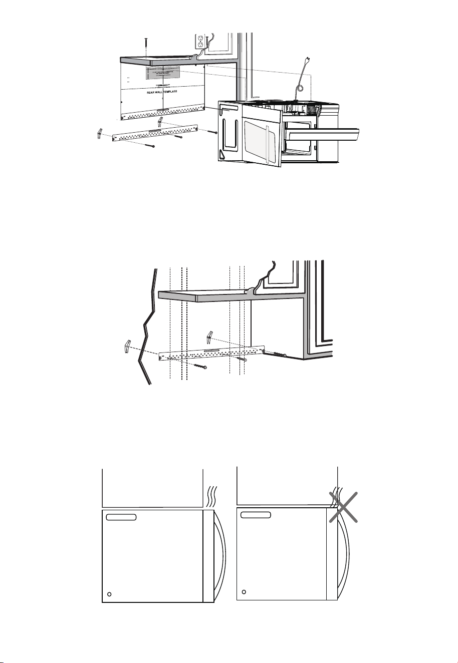
B3. ATTACH THE MOUNTING PLATE TO THE WALL
Attach the plate to the wall using toggle bolts. At least one wood screw must be used to
attach the plate to a wall stud.
1. Remove the toggle wings from the bolts.
2. Insert the bolts into the mounting plate through the holes designated to go into
drywall and reattach the toggle wings to 3⁄4" (19 mm) onto each bolt.
To use toggle bolts:
Spacing for Toggles
More Than Wall
Thickness
Toggle Wings
Toggle
Bolt
Wall
Mounting
Plate
Bolt End
3. Place the mounting plate against the wall and insert the toggle wings into the holes in
the wall to mount the plate.
NOTE:
Before tightening toggle bolts and wood screw, make sure the bottom of the mounting
plate touch the bottom of the cabinet when pushed flush against the wall and that the
plate is properly centered under the cabinet.
CAUTION:
Be careful to avoid pinching fingers between the back of the mounting plate and the
wall.
4. Tighten all bolts. Pull the plate away from the wall to help tighten the bolts.
EN-36
B4. USE TOP CABINET TEMPLATE FOR PREPARATION OF TOP CABINET
You need to drill holes for the top sup-port screws and a hole large enough for the power
cord to fit through.
1. Read the instructions on the TOP CABINET TEMPLATE.
2. Tape it underneath the top cabinet.
3. Drill the holes, following the instructions on the TOP CABINET TEMPLATE.
CAUTION:
Wear safety goggles when drilling holes in the cabinet bottom.
B5. ADAPTING MICROWAVE BLOWER FOR OUTSIDE BACK EXHAUST
1. Remove and save screw that holds blower motor to microwave.
Blower Motor
Back of
Microwave
Blower Motor
Screw
2. Carefully pull out the blower unit. The wires will extend far enough to allow you to
adjust the blower unit.
Before: Fan Blade
Openings Facing
Forward
End B
End A
EN-37
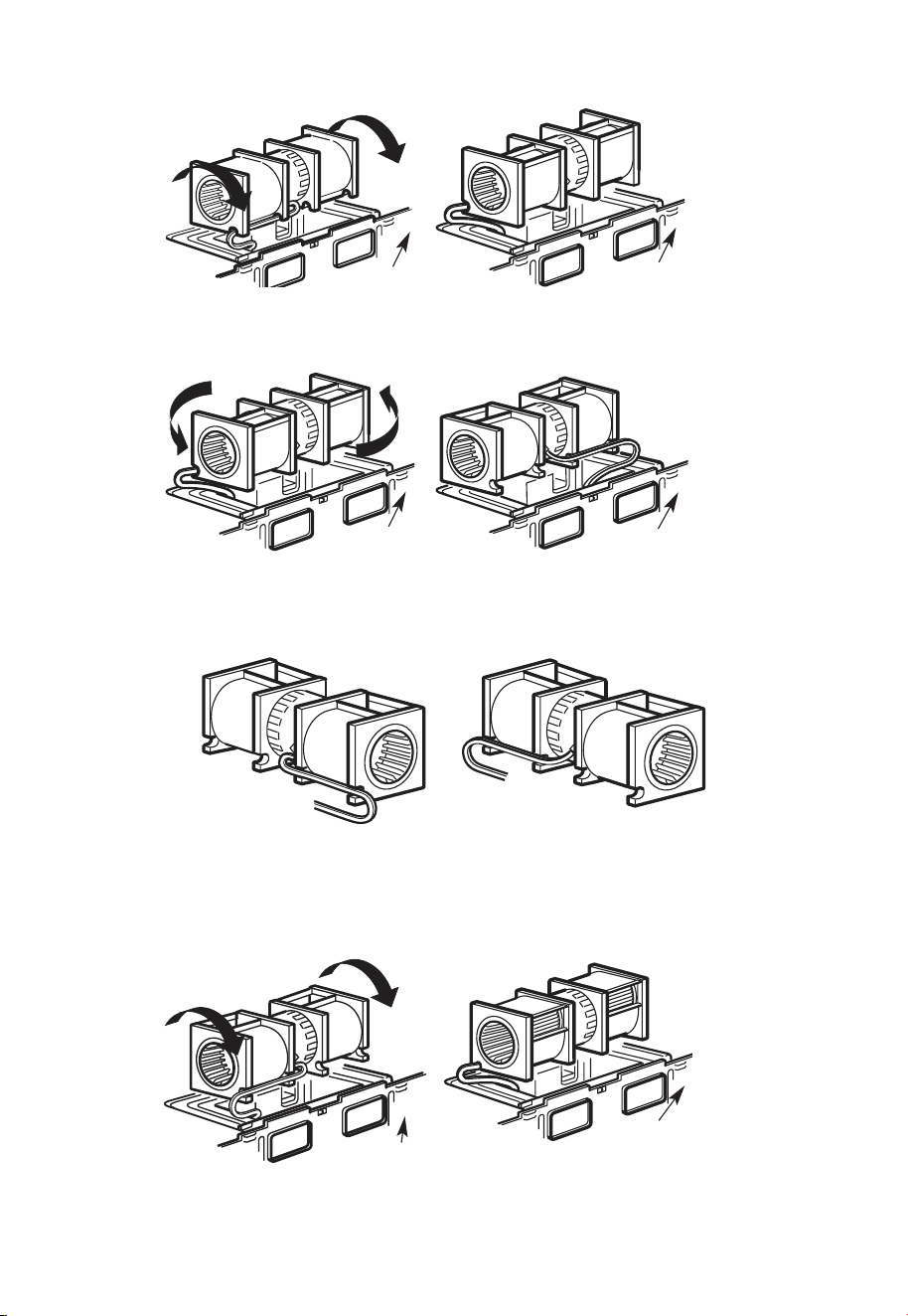
3. Roll the blower unit 90°
Before Rotation
Back of
Microwave
Back of
Microwave
After Rotation
4. Rotate blower unit counterclockwise 180°.
Before Rotation
After Rotation
Back of
Microwave
Back of
Microwave
5. Gently remove the wires from the grooves. Reroute the wires through grooves on
other side of the blower unit.
Before Rotation
Wires Routed
Through Right Side
Wires Routed
Through Left Side
After Rotation
6. Rotate the blower unit 90° so that fan blade openings are facing out the back of the
mi-crowave.
Before Rolling
After Rolling
Back of
Microwave
Back of
Microwave
EN-38
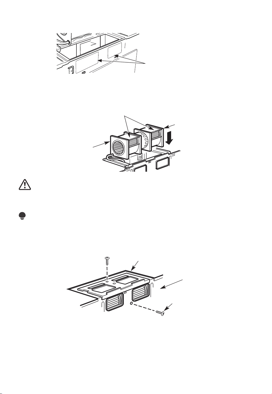
7. Remove the knockout plates in the back of the unit with snips. (for some models)
Knockout Plates:
Snip all 4 webs on each
knockout panel and remove
the metal knockouts for rear
airflow. Please take care to
remove any sharp edges
created from removing the
knockout plates.
Back of Microwave
8. Place the blower unit back into the opening.
AFTER: Fan Blade
Openings Facing Back
End A
End B
CAUTION:
Do not pull or stretch the blower unit wiring. Make sure the wires are not pinched, and
that they are properly secured.
NOTE:
The blower unit exhaust openings should match exhaust openings on rear of microwave
oven.
9. Secure the blower unit to the microwave with the original screw.
Blower Plate
Back of
Microwave
Blower Motor
Screw
10. Replace the blower plate in the same position as before with the screw. Make sure the
screw is tight.
EN-39
11. Attach the exhaust adaptor to the rear of the oven by sliding it into the guides at the
top center of the back of the oven.
Adaptor
Back of
Microwave
Guide
Locking Tabs
Guide
Push in securely until it is in the lower locking tabs. Take care to assure that the damper
hinge is installed so that it is at the top and that the damper swings freely.
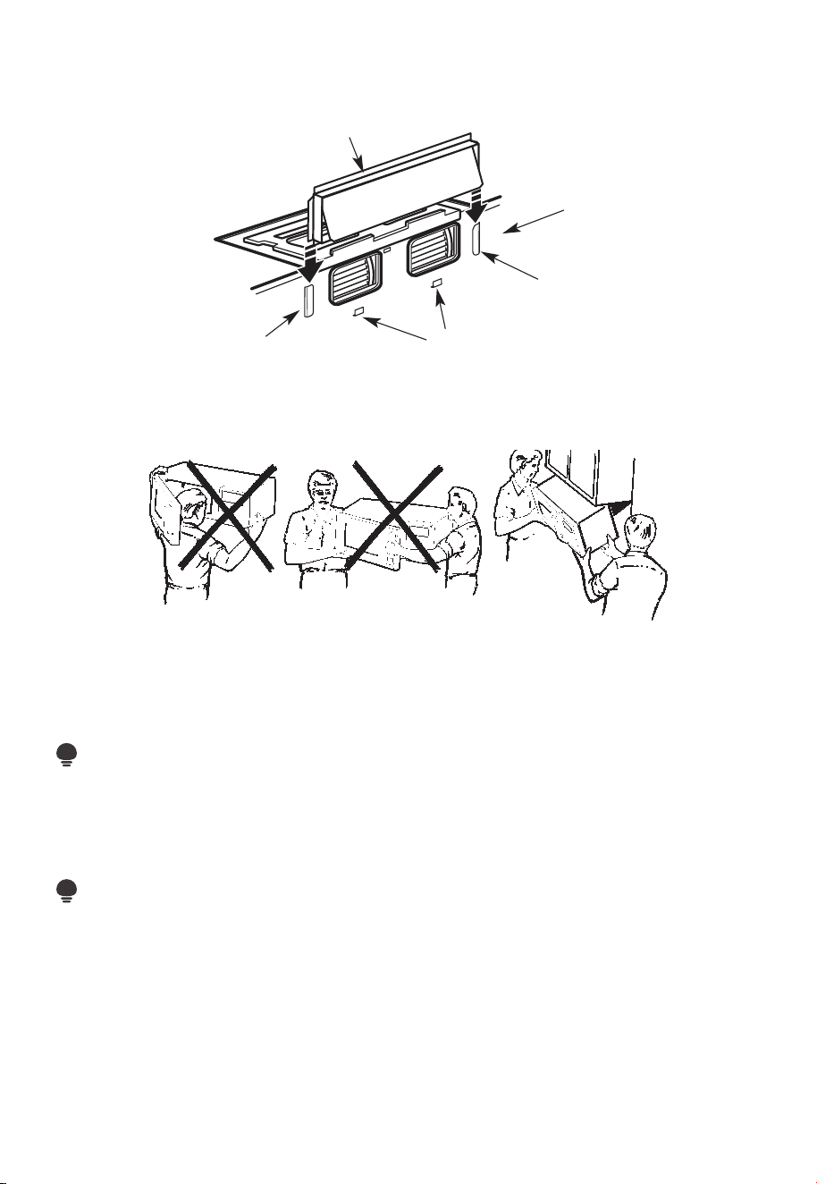
B6. MOUNT THE MICROWAVE OVEN
FOR EASIER INSTALLATION AND PERSONAL SAFETY, WE RECOMMEND THAT TWO
PEOPLE INSTALL THIS MICROWAVE OVEN.
IMPORTANT: Do not grip or use the handle or heat shield during in-stallation. Do not
remove the cardboard spacers between the heat shield and door.
NOTE:
If your cabinet is metal, use the nylon grommet around the power cord hole to prevent
cutting of the cord.
NOTE:
We recommend using filler blocks of the cabinet front hangs below the cabinet bottom
shelf.
IMPORTANT: If filler blocks are not used, case damage may occur from over tightening
screws.
EN-40
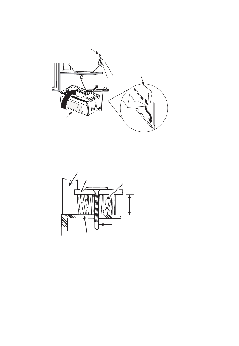
NOTE: When mounting the
microwave oven, thread power
cord through hole in bottom
of top cabinet. Keep it tight
throughout steps 1-3. Do not
pinch cord or lift oven by pulling
cord.
1. Lift microwave, tilt it forward,
and hook slots at back
bottom edge onto four lower
tabs of mounting plate.
2. Rotate front of oven up
against cabinet bottom.
3. Insert self-aligning screw through top center cabi-net hole. Temporarily secure the
oven by turning the screw at least two full turns after the threads have engaged (it will
be completely tightened later). Be sure to keep the power cord tight. Be careful not to
pinch the cord, especially when mounting flush to bottom of cabinet.
Cabinet Front
Cabinet Bottom Shelf
Filler Block
Equivalent to Depth
of Cabinet Recess
Self-Aligning Screw
Microwave Oven Top
4. Attach the microwave oven to the top cabinet.
EN-41
5. Insert 2 self-aligning
screws through outer top
cabinet holes. Turn two
full turns on each screw.
6. Tighten the outer two screws to the top of the microwave oven. (While tightening
screws, hold the microwave oven in place against the wall and the top cabinet.)
7. Install grease filters. See the Use & Care Guide that came with the microwave for more
information.
C. RECIRCULATING (non vented ductless)
INSTALLATION OVERVIEW
C1. Attach Mounting Plate to Wall
C2. Prepare Top Cabinet
C3. Check Blower Plate
C4. Mount the Microwave Oven
C5. Install or change Charcoal Filter
EN-42
12
"
4"
R
N
O
EA
T
D
E
:
A
IT
N
I
D F
S VE
O
L
R
L
Y
O
I
W
MP
T
O
H
E
R
T
D
A
I
R
N
E
T
C
T
T
I
O
O
IN
T
H
E
IN
ST
ALL
AT
I
O
N
I
N
ST
R
U
CTI
O
N
N
S
S
BEF
ORE
PR
O
C
EE
D
INGW
IT
H
T
HI
S
REAR W
ALL
TEM
P
L
AT
E
.
T
e
mp
l
ate
se
rv
e
s t
o
p
mo
t
U
u
le
s
n
t
e
.
ti
1
o
.
u
Th
i
s Re
n
a
g
r
pl
W
a
a
te
l
l
an
d
to
l
o
c
a
t
h
t
e
eh
o
r
i
z
o
o
sit
n
t
i
o
a
l
n
e
t
x
h
h
e
a
b
u
s
ot
t
t
o
m
et
oche
c
k
t
h
a
t
t
h
e
t
emp
l
a
t
e is
p
osition
d
L
oc
ou
n
t
i
n
AN
T:
I
m
MPO
R
T
E
AT
L
at
e
a
g
n
d
pl
a
m
te
a
.
r
k hol
es to
a
lig
n
w
i
t
h hol
e
s
in
t
h
e
LOC
AT
NT
ER
L
E
IN
AS
E
.
T
O
NESTUD
O
N
E
I
T
H
E
R
SID
E
OF
T
H
E
CE
HEL
O
CA
T
I
SP
ACE
AREA.
MARK
T
D
TO
G
GLE
B
O
OL
N F
TS
O
I
R
N
2
T
A
H
D
E
DI
M
T
O
IO
U
N
N
T
AL
I
N
,
E
G
V
P
E
L
N
AT
LY
E
o
unt
i
n
:
L
o
c
a
t
e
a
g
n
d
p
lat
ma
e
.
rk holes t
o
a
l
i
gn
w
i
t
h
h
ol
es
in
t
h
e
I
m
M
P
O
RT
E
A
N
A
T
T
L
LO
C
AT
NT
E
RL
E
I
A
NE
ST
.
O
N
ESTUD
O
N EI
TH
E
R S
IDE
O
F
THECE
H
E
LOCAT
I
SPA
C
A
RE
A
.
MARK
ED
T
T
O
GG
LE
BO
ON
F
L
T
S
OR
IN
2
T
A
H
D
E
DIT
M
O
IO
U
N
N
A
T
I
L
,
N
E
G
VE
P
L
A
NL
T
Y
E
T
r
im
t
h
e
rear
w
a
l
l te
m
p
lat
e
a
lon
g
t
he
d
o
t
ted
l
in
e.
3
/8
"
TO
EDG
E
Trim the re
ar
wall t
em
pla
t
e alongthe dotte
d l
in
e.
L
a
o
c
c
c
a
u
a
t
r
e
a
t
lev
a
el
n
y
e
d
.
l
2
.
m
a
r
k
at
l
ea
st o
nes
tud
on
t
he l
ef
t
o
r
rig
h
t
s
i
de
o
f
the
c
en
te
rl
i
ne
.
It
a
t
rop
mi
s
i
nt
t
o
u
s
e
a
t
l
e
asto
n
e w
o
od
n
t
w
e
a
v
d
f
e
i
.
rm
M
ly
a
r
i
k
n
t
a
w
s
o
t
u
a
d
d
d
t
i
o
t
i
o
s
n
u
a
p
l,
p
o
e
r
v
t
e
t
h
n
e
ly
w
s
p
ei
a
g
h
c
e
t
d
o
o
r
s
i
t
h
nt
e s
h
u
e
p
m
p
l
a
i
r
e
d
ke
t
d
o
l
g
o
g
c
l
a
e
t
b
io
o
l
n
t
s
s
.
.
W
here
th
e
r
e
i
s
l
s
3
o
f
o
.
c
r
c
t
t
t
a
D
a
e
h
h
o
t
r
i
e
s
w
g
a
i
l
o
t
t
l
g
u
n
m
l
m
d
ho
d
s
i
e
o
o
,
c
r
f
l
u
d
e
ril
l
a
3
/16"
h
o
le
fo
r
wood sc
re
w
s
.
F
orho
l
e
s
n ne u
p
with
a
s
tu
d
,
d
r
i
ll5
/8
"
h
o
l
e
sf
o
r
o
l
t
t
N
s.
l
i
OD
bo
TI
NSTALL
TH
E
M
OU
NTI
N
GPL
A
TE
AT
R
T
HI
m
S
v
e
TI
O
M
E.
4
.
e
o
t
h
e
te
m
p
lat
e
f
ro
m
t
h
e
rea
r
wa
ll.
5
.
Re
vie
wth
e
In
s
t
all
a
t
i
on
In
s
t
ruct
i
o
n
b
ook f
or
y
ou
r
in
s
t
a
l
lat
io
n
s
i
t
ua
t
i
o
n.
Darlev
ue
l
ta
a
l
a
ho
ja
pa
r
acons
u
ltar
la
v
e
r
s
ión
e
nEspañol.
IMPORTANT NOTES:
1. Make sure the screws for the blower motor and blower plate are securely tightened
when they are reinstalled. This will help prevent excessive vibration.
2. Make sure the motor wiring has been properly routed and secured and that the wires
are not pinched.
C1. ATTACH THE MOUNTING PLATE TO THE WALL
Attach the plate to the wall using toggle bolts. At least one wood screw must be used to
attach the plate to a wall stud.
If the cabinet depth including the cabinet doors is more than 13", then the unit must be
spaced out from wall using adequate materials supporting 150 Ibs to allow proper top
vent air exhaust/intake.
Cabinet Cabinet
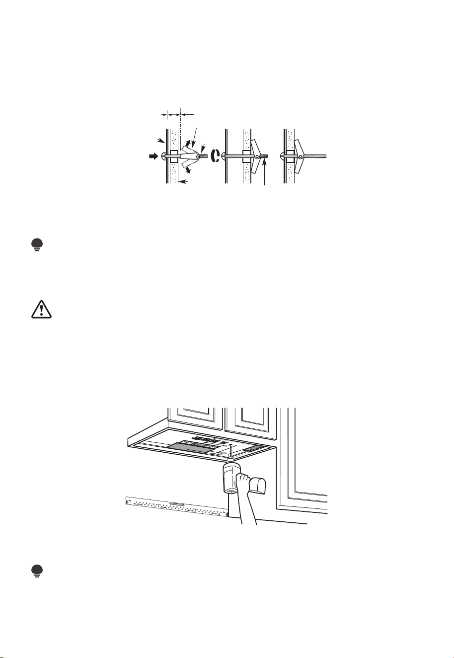
EN-43
1. Remove the toggle wings from the bolts.
2. Insert the bolts into the mounting plate through the holes designated to go into
drywall and reattach the toggle wings 3/4" to (19mm) onto each bolt.
To use toggle bolts:
Spacing for Toggles
More Than Wall
Thickness
Toggle Wings
Toggle
Bolt
Wall
Mounting
Plate
Bolt End
3. Place the mounting plate against the wall and insert the toggle wings into the holes in
the wall to mount the plate.
NOTE:
Before tightening toggle bolts and wood screw, make sure the bottom of the mounting
plate touch the bottom of the cabinet when pushed flush against the wall and that the
plate is properly centered under the cabinet.
CAUTION:
Be careful to avoid pinching fingers between the back of the mounting plate and the
wall.
4. Tighten all bolts. Pull the plate away from the wall to help tighten the bolts.
C2. USE TOP CABINET TEMPLATE FOR PREPARATION OF TOP CABINET
You need to drill holes for the top support screws and a hole large enough for the power
cord to fit through.
1. Read the instructions on the TOP CABINET TEMPLATE.
2. Tape it underneath the top cabinet.
NOTE:
Adjust top template accordingly if the microwave is being spaced out from the wall due
to cabinet depth (including cabinet doors) of more than 13".
Drill the holes following instructions on the TOP CABINET TEMPLATE.
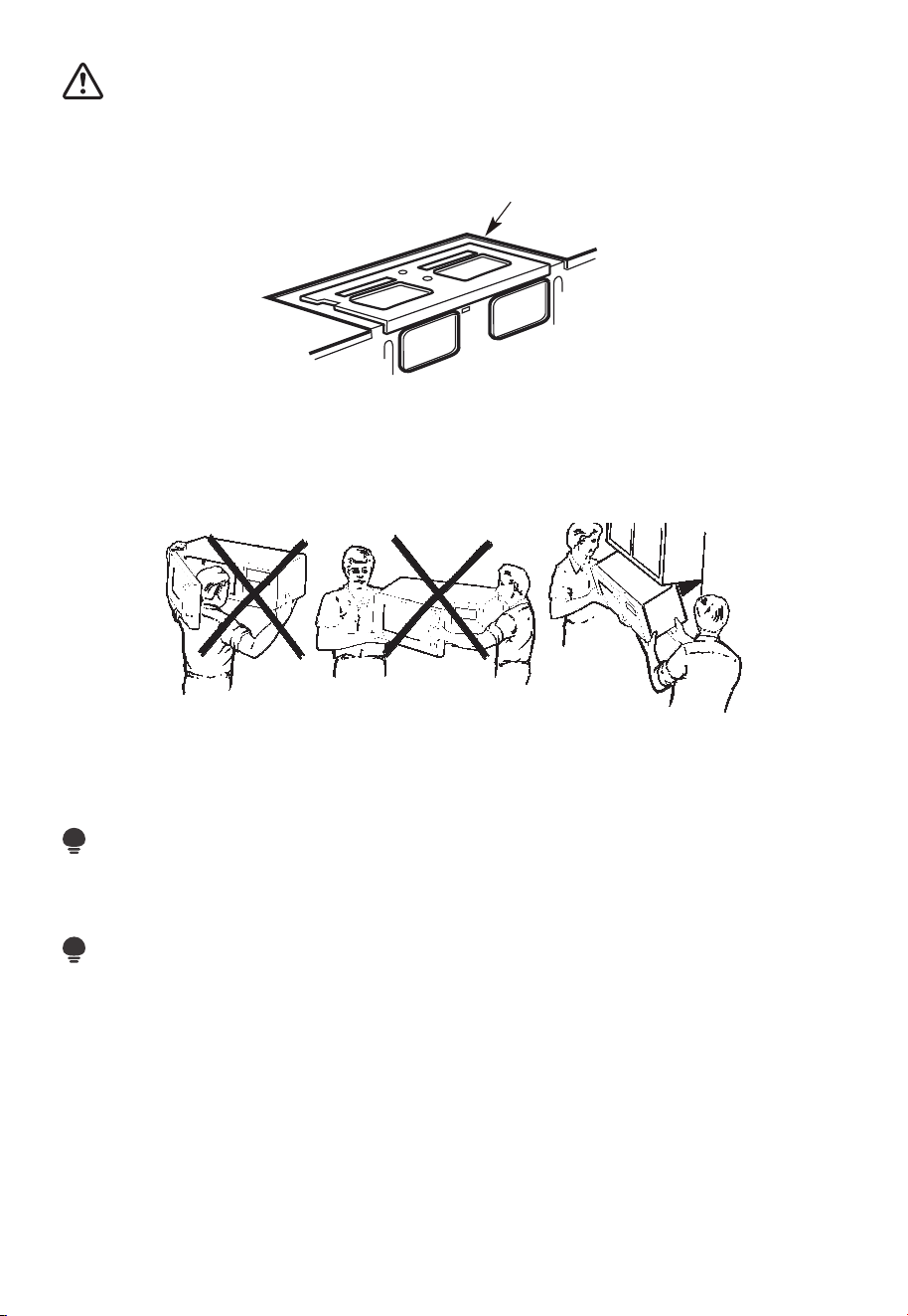
EN-44
CAUTION:
Wear safety goggles when drilling holes in the cabinet bottom.
C3. CHECK BLOWER PLATE
Blower Plate
Place the microwave in its upright position, with the top of the unit facing up.
Check to see that the blower plate is cor-rectly installed on the unit.
C4. MOUNT THE MICROWAVE OVEN
FOR EASIER INSTALLATION AND PERSONAL SAFETY, WE RECOMMEND THAT TWO
PEOPLE INSTALL THIS MICROWAVE OVEN.
IMPORTANT: Do not grip or use the handle or heat shield during installation. Do not
remove the cardboard spacers between the heat shield and door.
NOTE:
If your cabinet is metal, use the nylon grommet around the power cord hole to prevent
cutting of the cord.
NOTE:
We recommend using filler blocks if the cabi-net front hangs below the cabinet bottom
shelf.
IMPORTANT: If filler blocks are not used, case dam-age may occur from over tightening
screws.
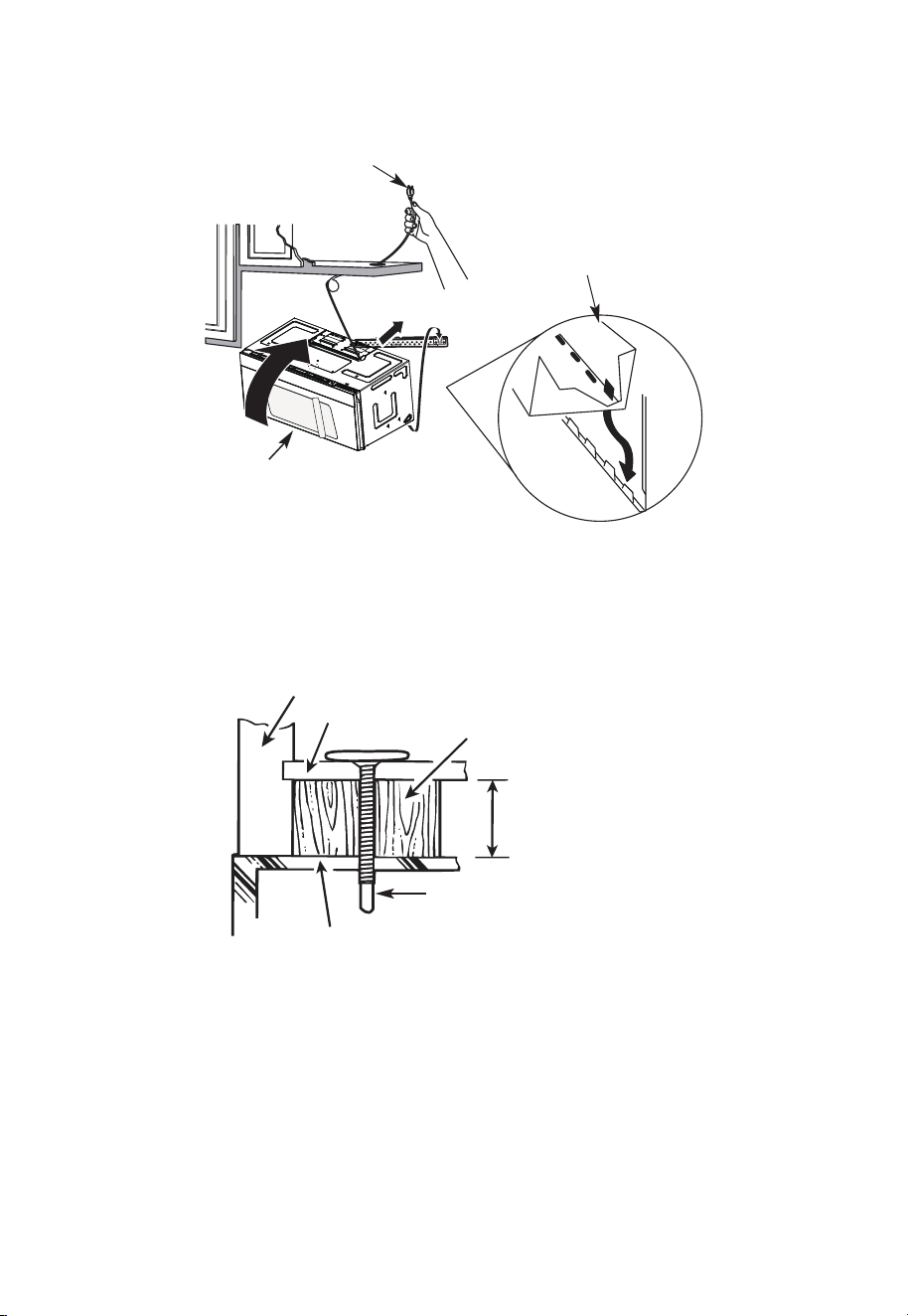
EN-45
NOTE: When mounting the
microwave oven, thread power
cord through hole in bottom of top
cabinet. Keep it tight throughout
steps 1-3. Do not pinch cord or lift
oven by pulling cord.
2. Rotate front of oven up
against cabinet bottom.
1. Lift microwave, tilt it
forward, and hook slots
at back bottom edge
onto four lower tabs of
mounting plate.
3. Insert a self-aligning screw through top center cabinet hole. Temporarily secure the
oven by turning the screw at least two full turns after the threads have engaged (It
will be completely tightened later.) Be sure to keep power cord tight. Be careful not to
pinch the cord, especially when mounting flush to bottom of cabinet.
Cabinet Front
Cabinet Bottom Shelf
Filler Block
Equivalent to Depth
of Cabinet Recess
Self-Aligning Screw
Microwave Oven Top
4. Attach the microwave oven to the top cabinet.
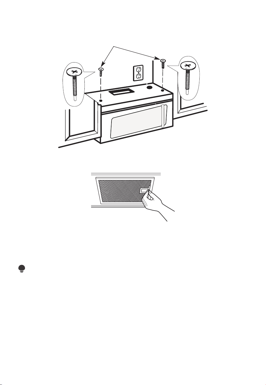
EN-46
5. Insert 2 self-aligning screws
through outer top cabinet holes.
Turn two full turns on each
screw.
6. Tighten the outer two screws to the top of the microwave oven. (While tightening
screws, hold the microwave oven in place against the wall and the top cabinet.)
7. Install grease filters. See the Use & Care Guide packed with the microwave.
C5. INSTALLING OR CHANGING THE CHARCOAL FILTER (Some Models)
NOTE:
The charcoal filter is factory installed in some models. Refer to the Use & Care Guide to
see if yours is factory installed and for replacement information.
For models without the recirculation filter access door, follow these steps to replace or
install a charcoal filter:
1. Unplug microwave oven or disconnect power.

EN-47
2. Open the microwave door and remove the two vent mounting screws located on top
of the microwave using a #1 Phillips screwdriver.
Charcoal
Filter
3. Remove the charcoal filter by pushing the top of the filter inwards,then pull it forward
out from the unit.
4. Slide the top of the new charcoal filter into the top of the filter cavity.
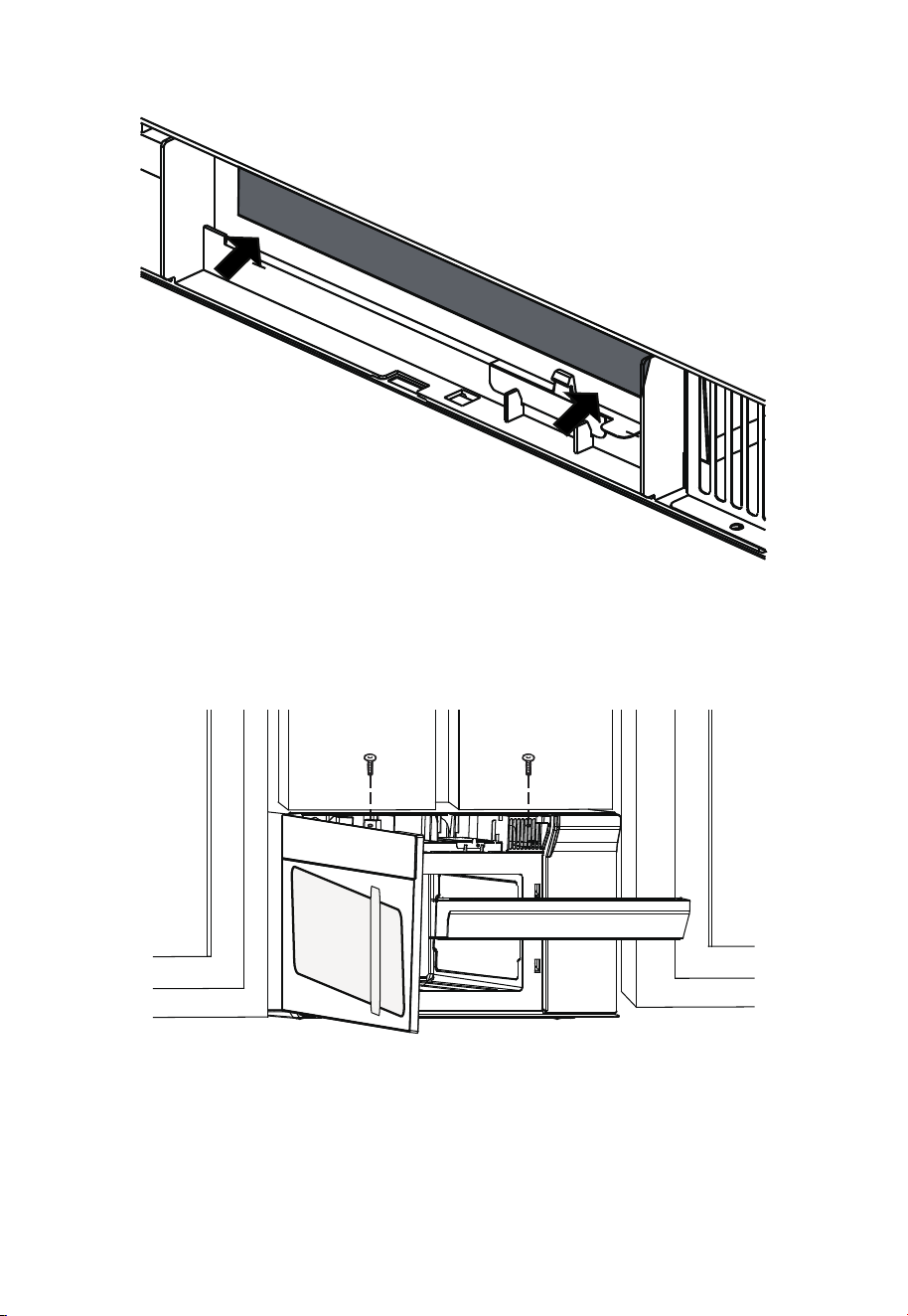
EN-48
5. Press the bottom of charcoal filter to place it into the correct position.
6. Reinstall the vent by sliding the bottom of the vent into place. Push the vent top into
position and slide right into place. Replace the two vent mounting screws located on
top of the microwave using a #1 Phillips screwdriver.
7. Close the microwave door. Plug in microwave oven or reconnect power.
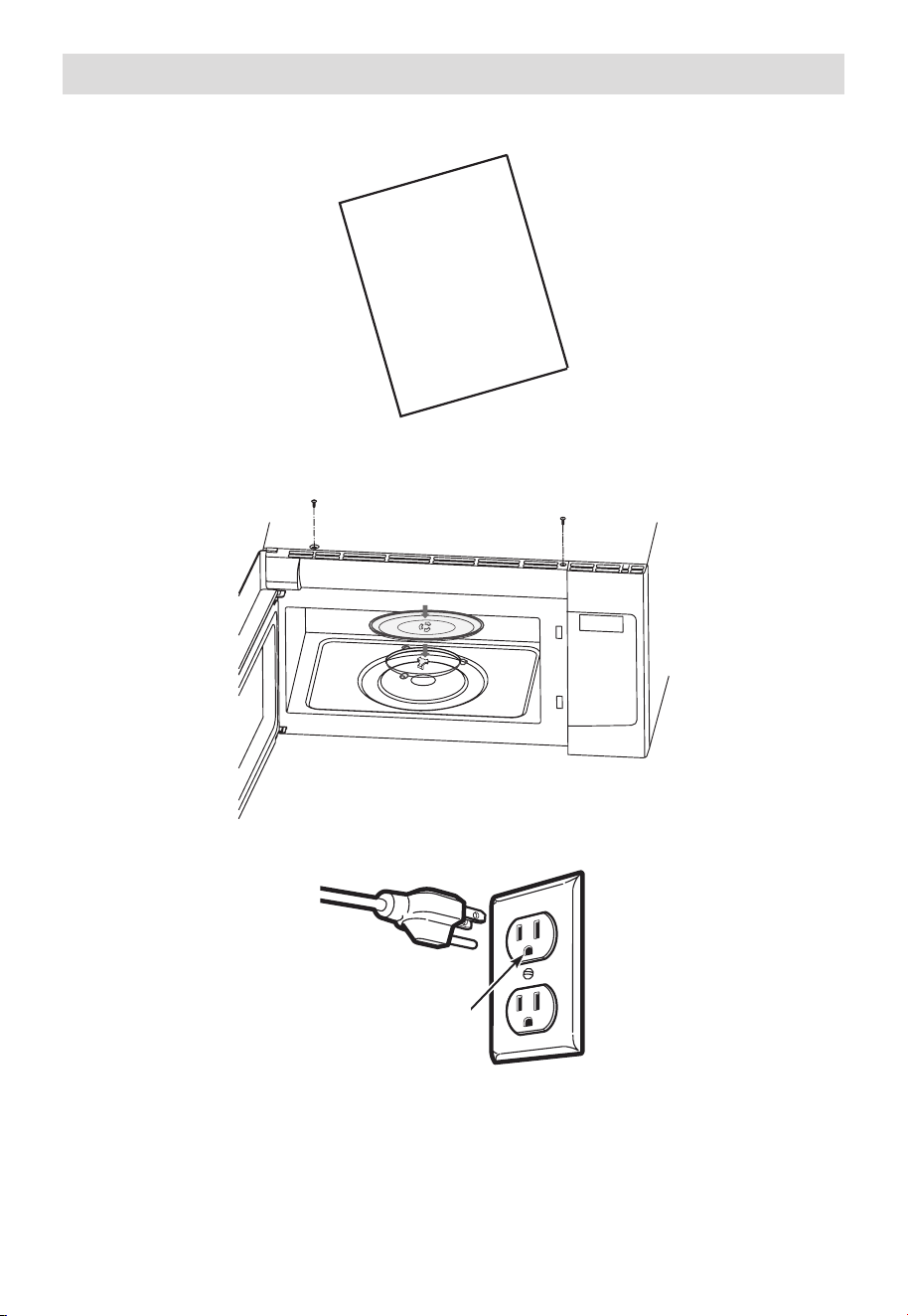
EN-49
Before You Use Your Microwave
1. Make sure the microwave oven has been installed according to instructions.
USER
MANUAL
2. Remove all packing material from the microwave oven.
3. Install turntable ring and glas stray in cavity.
4. Plug power cord into a seperate and dedicated 15- to 20-amp electrical outlet.
Ensure proper
ground exists
before use
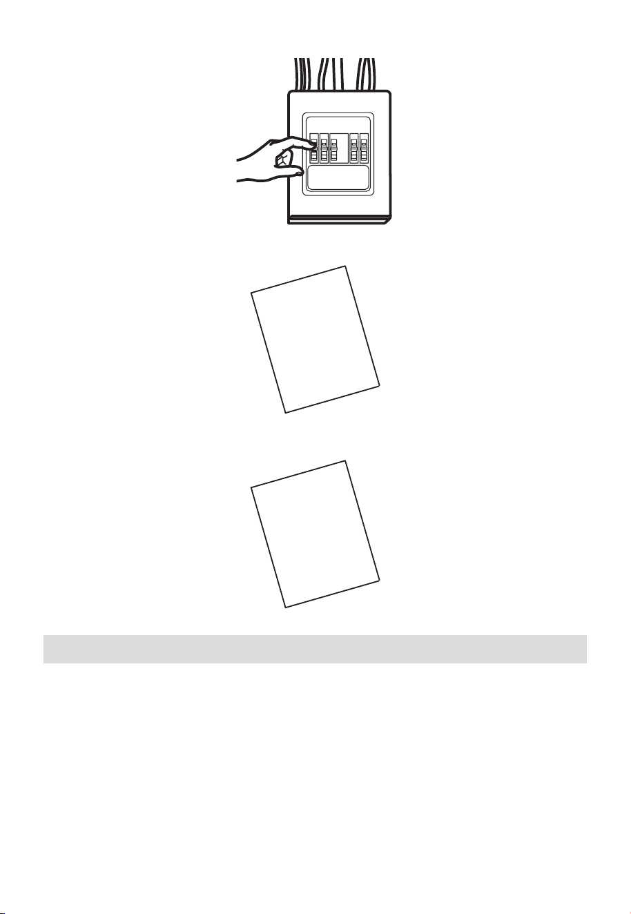
EN-50
5. Replace house fuse or turn breaker back on.
6. Read the User Manual.
USER
MANUAL
7. KEEP USER MANUAL FOR THE LOCAL INSPECTOR’S USE.
USER
MANUAL
Operational Check
1. Make sure the unit has been installed according to these instructions.
2. Remove all packing materials from the oven.
3. Replace house fuse or turn circuit breaker back on.
4. Plug power cord into receptacle.
5. Read operating instructions before testing the product.
6. Turn on the exhaust fan at Turbo speed and confirm it is operating by using a tissue (it
will stick to the filter).
7. Confirm the outdoor ex-haust flapper has opened.
8. Set the microwave oven for 1 minute and confirm the oven is operat-ing normally using
a cup of water.
9. Keep these installation instruction for the local electrical inspector’s use.
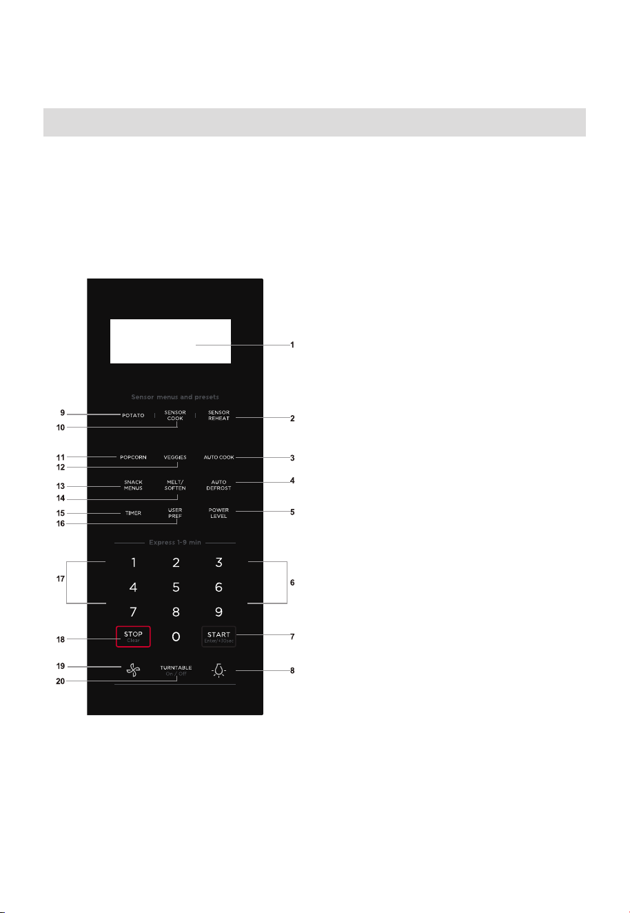
EN-51
OPERATION INSTRUCTIONS
Control Panel
(1) Display:
The display includes a clock and indicators that
show the time of day, cooking time settings, cook
powers, sensor, quantities, weights and cooking
functions selected.
(2) Sensor Reheat (5 different settings)
(3) Auto Cook
(4) Auto Defrost
(5) Power Level (11 power levels available)
(6) Numeric pads (0 thru 9)
(7) START +30 sec
(8) Surface Light (High/Low/Off)
~Press this pad to adjust the brightness of
surface lights.
(9) Potato (1-4 potatoes)
(10) Sensor Cook
(11) Popcorn
(12) Veggies
(13) Snack Menus
(14) Melt/Soften
(15) Timer (On-Off)
(16) User pref
(17) Quick Start ( 9 instant key settings)
(18) Stop/Clear
(19) Exhaust (High/Low/Off) ~ Use to turn the
exhaust fan off, or to adjust fan speed.
(20) Turntable (On-Off)
/Enter/
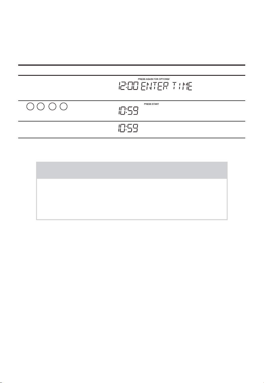
EN-52
• Before operating your new oven make sure you read and understand this
MANUAL completely.
• The clock can be disabled when the microwave is first plugged in and the Stop/Clear
key is selected. To re-enable the clock follow clock instructions.
To Set the Clock
• Suppose you want to enter the correct time of day 10:59
Touch: Display Shows:
1. User pref
2.
1 0 5 9
3. "Start/Enter/+30 Sec"
NOTE
1. If you begin to enter in an incorrect time (e.g. 2:89) the 8 is an
invalid digit and cannot be entered. Enter the correct time.
2. If you touch "Stop Clear" while setting the clock, the display
will show the last time of day set or a blank display if no time of
day has been set.
MANUAL COOKING
Time Cooking
Your Over the Range Microwave Oven can be programmed for 99
minutes 99 seconds (99:99). Always enter the seconds after the
minutes, even if they are both zeros.
• Suppose you want to cook for 5 minutes, 30 seconds at 100% power,
USER
When the oven is plugged into an outlet, please skip this step.( )
/
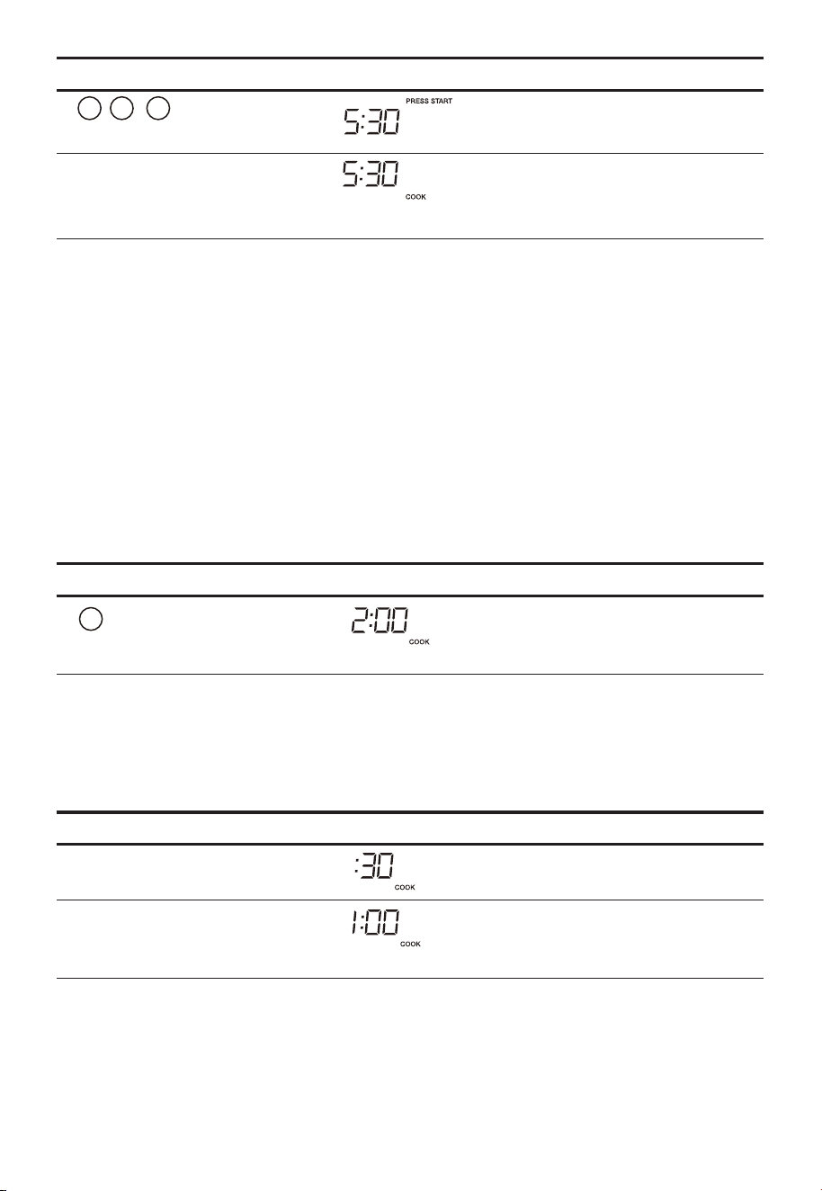
EN-53
Touch: Display Shows:
1.
5 3 0
2.
"Start/Enter/+30 Sec"
Time counting down
Interrupting Cooking
You can stop the oven during a cycle by opening the door. The oven
stops heating and the fan turns off, but the light stays on.
To restart cooking, close the door and touch "Start/Enter/+30 Sec".
If you do not want to continue cooking, open the door and touch "Stop
Clear"
Using One Touch Start
Numeric key 1~9 can be touched for a 1~9 minutes' automatic start
cooking feature.
This is a time saving pad that will automatically start cooking 2 seconds
after selected.
Touch: Display Shows:
1.
2
Time counting down
Using Add 30 Sec.
This is a time-saving pad. It is a simplified feature that lets you quickly
set and start microwave cooking at 100% power.
• Suppose you want to cook for one minute.
Touch: Display Shows:
1.
"Start/Enter/+30 Sec"
2.
"Start/Enter/+30 Sec"
Time counting down
/
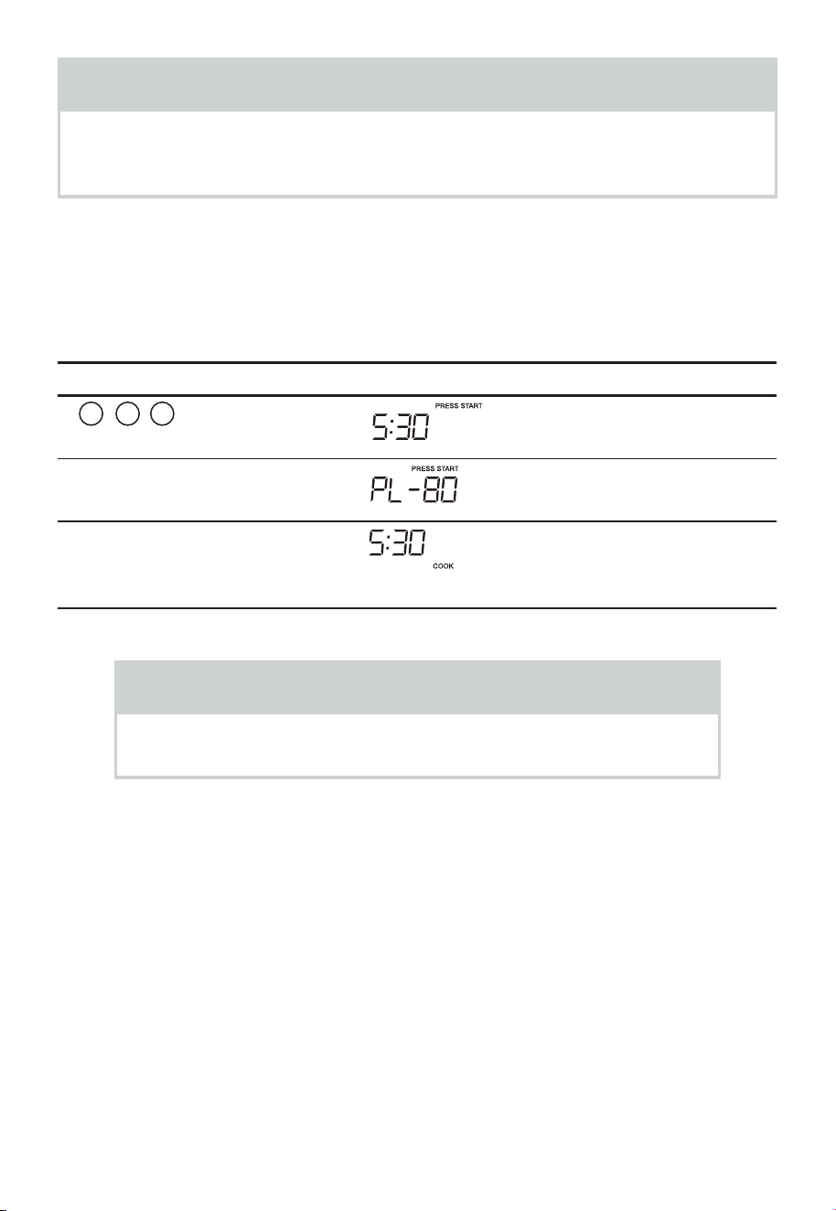
EN-54
NOTE
“Food” will be displayed if a quick start cooking cycle or +30 sec key is not
selected within 5 minutes of placing food in the microwave. You must open
then close the door again to clear ''Food" from the display.
Setting Timed Cooking With Power Level
This feature lets you program a specific cook time and power. For best
results, there are 10 power level settings in addition to HIGH (100%)
power.
• Suppose you want to cook for 5 minutes, 30 seconds at 80% power.
Touch: Display Shows:
1.
5 3 0
2.
"Power Level" 3 times
3.
"Start/Enter/+30 Sec"
Time counting down
NOTE
If you do not select a power level, the oven will automatically
cook at HIGH (100%) power.
Setting Two-Stage Cooking
For best results, some recipes call for different power levels during
a cook cycle. You can program your oven for two power level stages
during the cooking cycle.
• Suppose you want to set a 2-stage cook cycle. The first stage is a 3
minute cook time at 80% cook power then a 7 minute cook time at
50% cook power.
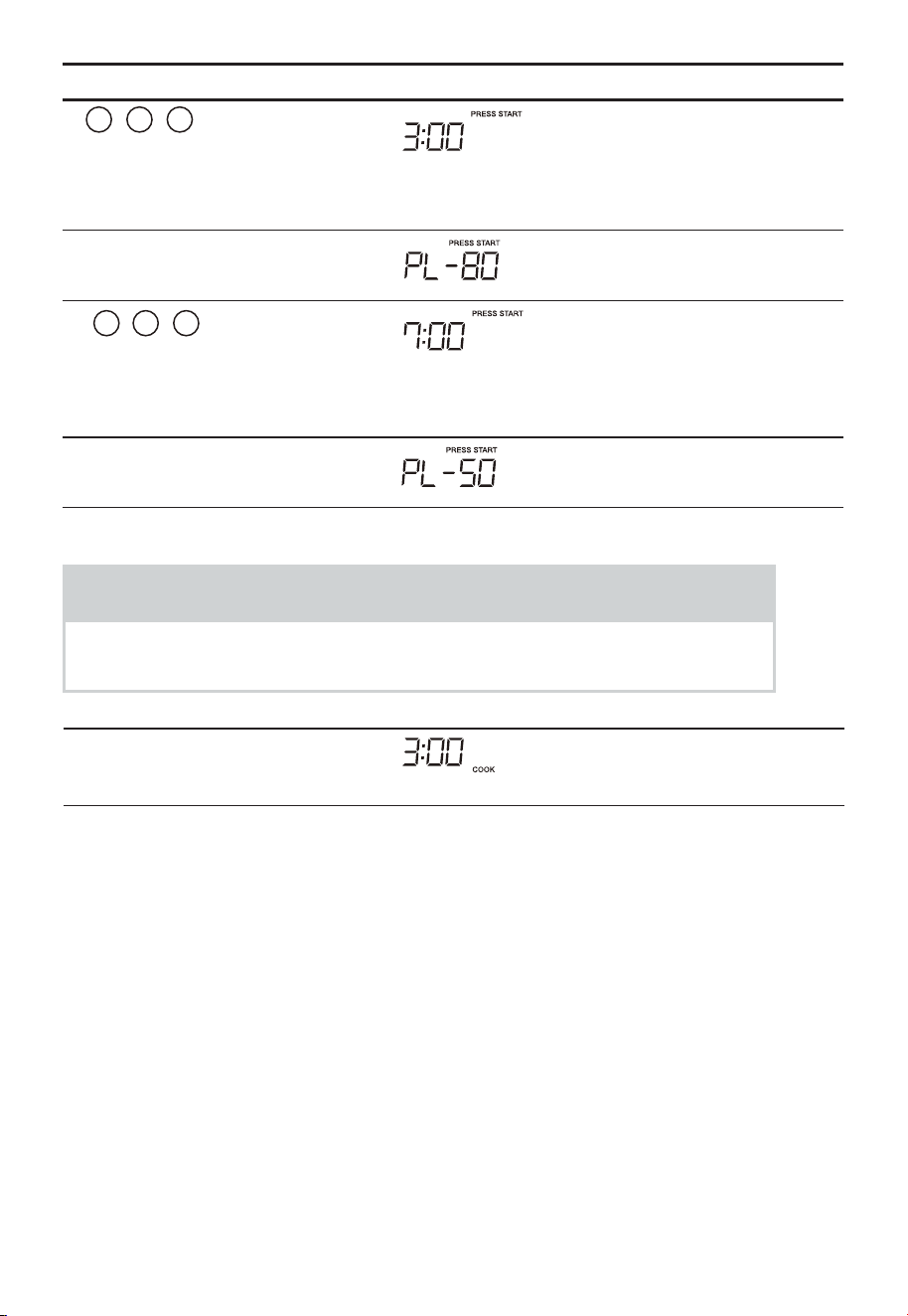
EN-55
Touch: Display Shows:
1.
3 0 0
To set a 3 minute
cook time for first
stage.
2.
"Power Level" 3 times
3.
7 0
0
To set a 7 minute
cook power for the
second stage.
4.
"Power Level" 6 times
NOTE
You can program a "0" power second stage for standing time inside
the oven.
5.
"Start/Enter/+30 Sec"
Time counting down

EN-56
To Set Power Level
There are eleven preset power levels.
Using lower power levels increases the cooking time which is
recommended for foods such as cheese, milk and long slow cooking of
meats. Consult cookbook or recipes for specific recommendations.
PRESS POWER LEVEL PAD
NUMBER OF TIMES FOR
DESIRED POWER
APPROXIMATE
PERCENTAGE OF POWER
COMMON WORDS FOR
POWER LEVELS
POWER LEVEL x 1 100% High
POWER LEVEL x 2 90%
POWER LEVEL x 3 80%
POWER LEVEL x 4 70% Medium High
POWER LEVEL x 5 60%
POWER LEVEL x 6 50% Medium
POWER LEVEL x 7 40%
POWER LEVEL x 8 30% Med Low/Defrost
POWER LEVEL x 9 20%
POWER LEVEL x 10 10% Low
POWER LEVEL x 11 0%
Using the Rack
The rack allows several foods to be cooked or reheated at one time. However,
for the best cooking and reheating, use Turntable ON function and cook with
SENSOR COOKING or AUTO COOKING without the rack. When the rack is
used, set time and power level manually. Allow plenty of space around and
between the dishes.
Pay close attention to the cooking and reheating progress. Reposi- tion the
foods and reverse them from the rack to turntable and/or stir them at least
once during any cooking or reheating time. After cooking or reheating, stir if
possible. Using a lower power level will assist in better cooking and reheating
uniformity.
Avoid:
• Storing the rack in the microwave oven when not in use.
• Popping popcorn with the rack in the microwave oven.
• Using any browning dish on the rack.
• Using SENSOR COOKING and AUTO COOKING with the rack.
• Cooking directly on the rack—use microwave-safe cookware.

EN-57
NOTE
Turntable on/off function can be used in Manual Operation. See page .
Manual Defrost
If the food that you wish to defrost is not listed on the Defrost chart or
is above or below the limits in the amount column on the Defrost chart
(see page -7 ), you need to defrost manually.
You can defrost any frozen food, either raw or previously cooked,
by using power level for 30%.
For either raw or previously cooked frozen food cook approximately
4 minutes per pound. For example, defrost 4 minutes for 1 pound of
frozen spaghetti sauce.
Always stop the oven periodically to remove or separate the portions
that are defrosted. If food is not defrosted at the end of the estimated
defrosting time, program the oven in 1 minute increments on power
level 30% until totally defrosted.
When using plastic containers from the freezer, defrost only long
enough to remove from the plastic in order to place in a microwave-
safe dish.
SENSOR COOKING
Sensor cooking has an electronic controlled sensor that detects the
vapor (moisture and humidity) emitted from the food as it heats. The
sensor adjusts the cooking times and power level for various foods and
quantities automatically.
Using Sensor Settings:
1. Be sure the exterior of the cooking container and the interior of the
oven are dry. Wipe off any moisture with a dry cloth or paper towel.
2. The oven works with foods at normal storage temperature. For
example, popcorn would be at room temperature.
3. More or less food than the quantity listed in the chart should be
cooked following the guidelines in any microwave cookbook.
82
72 3

EN-58
4. During the first part of SENSOR COOKING, food name will appear
in the display. Do not open the oven door or press the STOP lear
pad during this part of the cycle. The meas- urement of vapor will be
interrupted.
When the sensor detects the vapor emitted from the food, remainder
of cooking time will appear. Door may be opened when remaining
cooking time appears in the display. At this time, you may stir or
season food, as desired.
5. If the sensor does not detect vapor properly when popping popcorn,
the oven will turn off, and the correct time of day will be displayed.
If the sensor does not detect vapor properly when cooking other
foods, AN ERROR CODE will be displayed, and the oven will turn off.
6. Check food for temperature after cooking. If additional time is
needed, continue to cook manually.
Covering Foods:
You may use the following to cover your foods:
1. Casserole lid.
2. Plastic wrap: Use plastic wrap recommended for microwave cooking.
Cover dish loosely; allow approximately 1/2 inch to remain uncovered
to allow steam to escape. Plastic wrap should not touch food.
3. Wax paper: Cover dish completely; fold excess wrap under dish to
secure. If dish is wider than paper, overlap two pieces at least one
inch to cover.
Be careful when removing any covering to allow steam to escape
away from you.
NOTES FOR SENSOR COOKING
1. The final cooking result will vary according to the food condition (e.g.
initial temperature, shape, quality). Check food for temperature after
cooking. If additional time is needed, continue to cook manually.
2. Stay near the oven while it’s in use and check cooking progress frequently
so that there is no chance of overcooking food.
3. When SENSOR COOKING is selected Turntable On is automatically set for
optimum cooking.
/ C
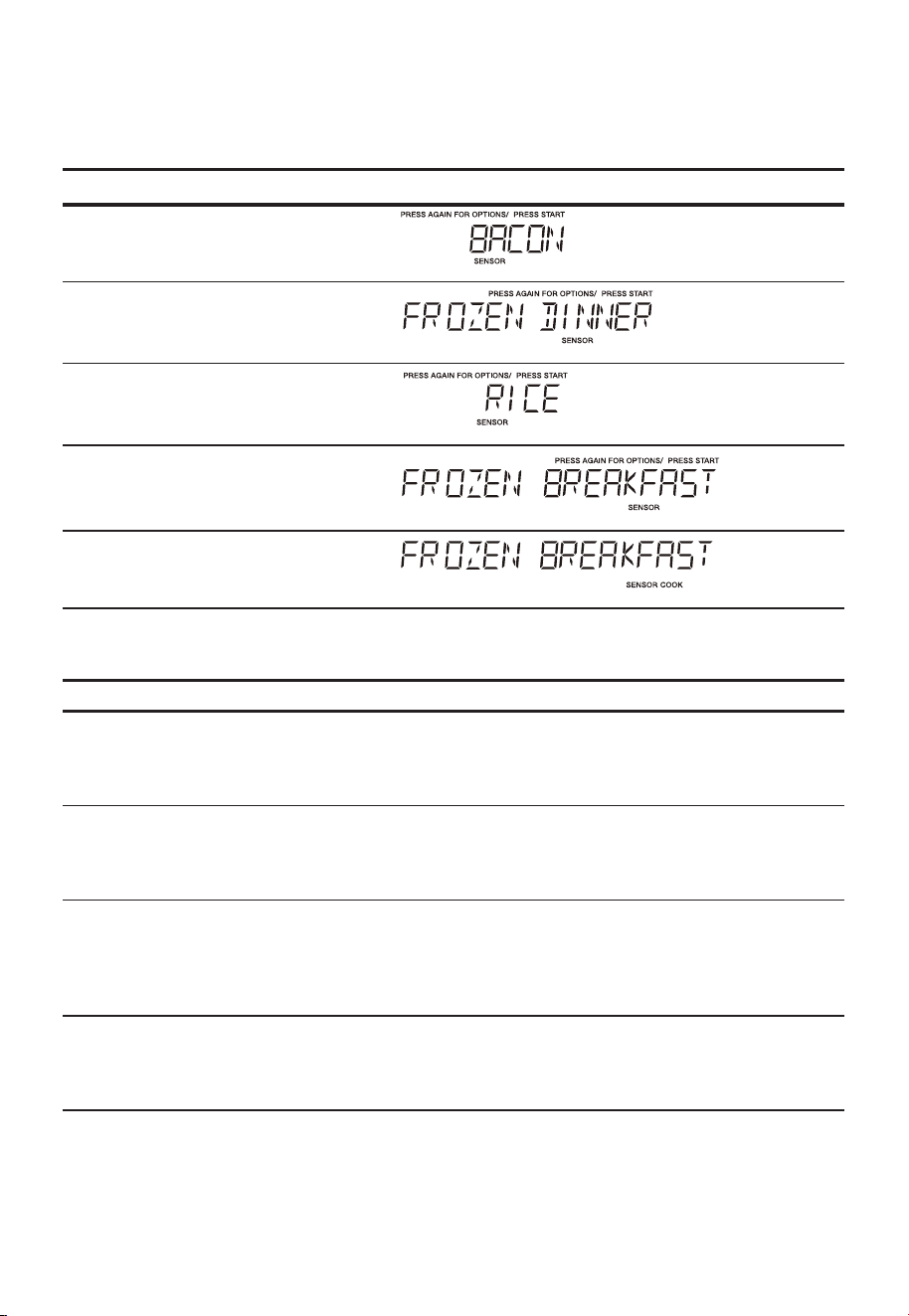
EN-59
Sensor Cook
You can cook foods by pressing the ensor ook pad multiple times.
You don’t need to calculate cooking time or power level.
• Suppose you want to cook frozen breakfast
Touch: Display Shows:
1.
"Sensor Cook"
2.
"Sensor Cook"
3.
"Sensor Cook"
4.
"Sensor Cook"
5.
"Start/Enter/+30 Sec"
Sensor Cook chart
FOOD AMOUNT PROCEDURE
1.Bacon 1-3 slices Place bacon strips on a microwave bacon
rack for best results. (Use dinner plate
lined with paper towels if rack is not
available).
2. Frozen Dinner 10 oz./ 20 oz. Place in an appropriately sized microwave
container. Cover with plastic wrap. After
cooking, stir and allow to stand for 3
minutes.
3. Rice 1-2 cups Place rice and twice as much liquid (water,
chicken or vegetable stock) in a 2 quart
microwave dish. Cover with plastic wrap
and vent. After cooking, allow to stand for
10 minutes. Stir for fluffier rice.
4. Frozen Breakfast 8-12 oz. Place in an appropriately sized microwave
container. Cover with plastic wrap. After
cooking, stir and allow to stand for 3
minutes.
S C
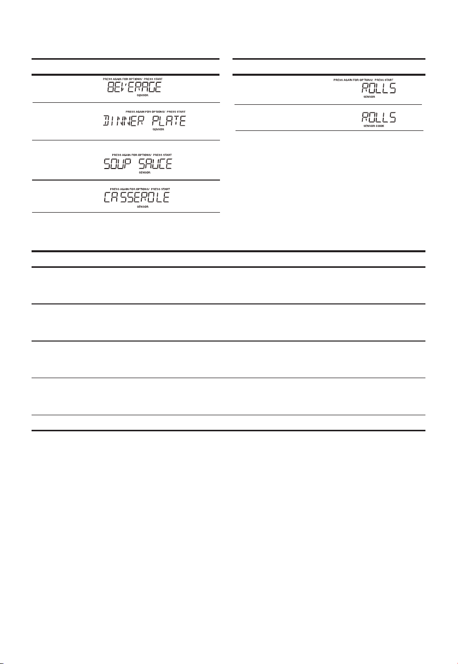
EN-60
Sensor Reheat
• Suppose you want to reheat rolls with sensor reheat.
Touch: Display Shows: Touch: Display Shows:
1. Sensor
Reheat
5. Sensor
Reheat
2. Sensor
Reheat
6.
3. Sensor
Reheat
4. Sensor
Reheat
Sensor Reheat chart
FOOD AMOUNT PROCEDURE
Beverage 1 - 3 cups To reheat beverages.
Stir liquid briskly before and after heating
to avoid ''eruption".
Dinner Plate 1-2 Plates Place on a low plate. Cover with vented
plastic wrap. Let stand 3 minutes after
cooking.
Soup/Sauce 1 Cup Place in shallow microwavable casserole.
Cover with vented plastic wrap. After
cooking, stir and let stand 3 minutes.
Casserole/Lasagna 10.5 Oz Place in a microwavable bowl or casserole.
Cover with vented plastic wrap. After
cooking, stir and let stand 3 minutes.
Roll/Muffin 1-3 Pieces Place on paper towel. Do not cover.
"Start/Enter/+30 Sec"
"
"
"
"
"
"
"
"
"
"
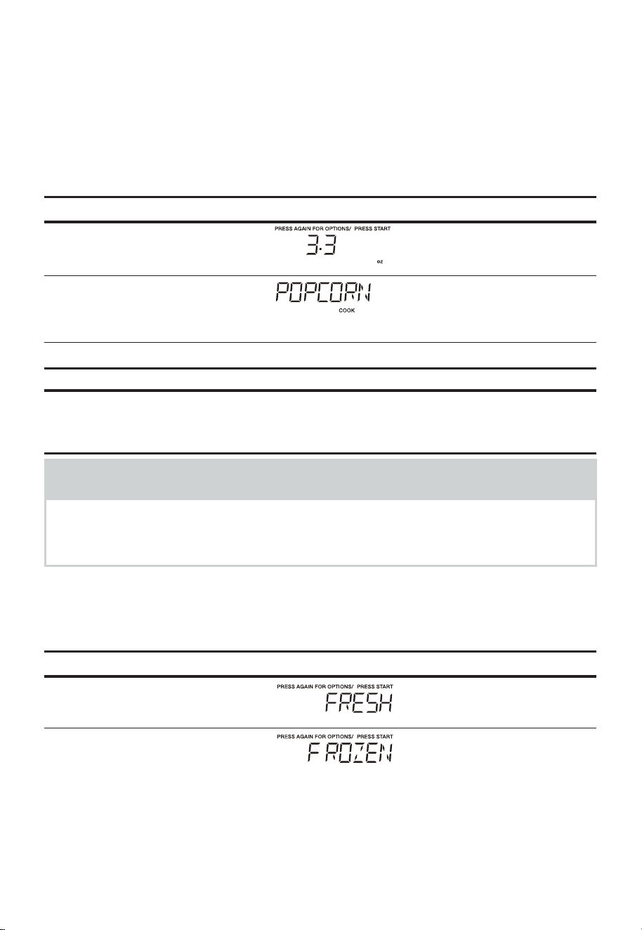
EN-61
ONE TOUCH COOKING
Popcorn
The Popcorn button on the quick touch pad lets you pop 3.3, 3.0, or
a 1.75 ounce bag of commercially packaged microwave popcorn. Pop
only one package at a time. If you are using a microwave popcorn
popper, follow manufacturer's instructions.
• Suppose you want to pop a 3.3 oz. popcorn.
Touch: Display Shows:
1.
"Popcorn"
2.
"Start/Enter/+30 Sec"
Time counting down
Amount Press popcorn pad
3.3oz. once
3.0 oz. 2 times
1.75 oz. 3 times
NOTES
1. Remove the metal shelf from the microwave oven when cooking popcorn.
Do not use regular paper bags. Do not re-pop un-popped kernels. Do not
pop popcorn in glass cookware.
Veggies
There are 2 options (Frozen Vegetables, Fresh Vegetables) under the
Veggies.
• Suppose you want to cook two cups of frozen veggies.
Touch: Display Shows:
1.
"Veggies"
2.
"Veggies"
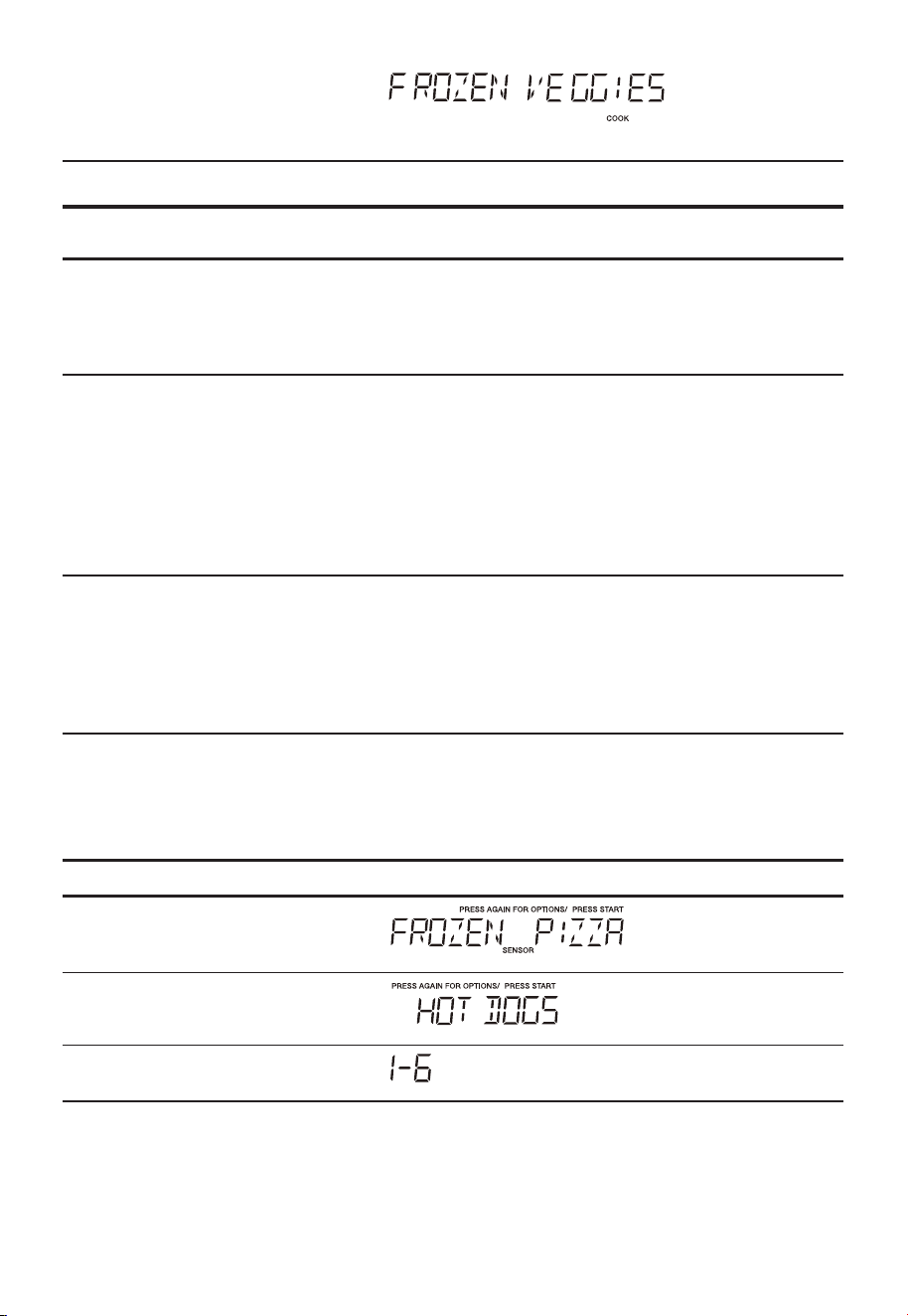
EN-62
3.
"Start/Enter/+30 Sec"
Time counting down
Vegetables chart
FOOD
(Initial temperature)
AMOUNT PROCEDURE
1. Frozen Veggies
(-18°C)
2 Cups No need to add water. Cover contents
with lid or plastic wrap.
Press the vegetables button two times for
Frozen Vegetables. After cooking, stir and
let stand, covered for 3 minutes.
2. Fresh Veggies
(5 °C)
Broccoli
Brussels sprouts
Cabbage
Cauliflower (flowerets)
Cauliflower (whole)
Spinach
Zucchini
2 Cups Wash and place in casserole. Add no water
if vegetables have just been washed.
Cover with lid for tender vegetables. Use
plastic wrap for tender-crisp vegetables.
Press the vegetables button once one
time for Fresh Vegeta-bles. After cooking,
stir, Let stand, covered, for 2 to 5 minutes.
Carrots, sliced
Corn on cob
Green beans
Winter squash
- diced
- halves
Wash and place in casserole. Add 1-4
tbsp. water. Cover with lid for tender
vegetables. Use plastic wrap cover
for tender-crisp vegetables. Press the
vegetables button one time for fresh
vegetables. After cooking stir, Let stand,
covered, for 2 to 5 minutes.
Snack Menu
Snack Menu is for cooking/heating foods that take a short amount of
time.
• Suppose you want to reheat 3 hot dogs.
Touch: Display Shows:
1.
"Snack Menus "
2.
3.
"Start/Enter/+30 Sec"
"Snack Menus "
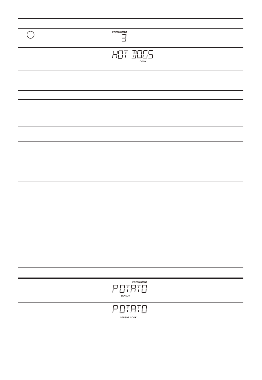
EN-63
Touch: Display Shows:
4.
3
5.
"Start/Enter/+30 Sec"
Time counting down
Snack Menu chart
FOOD AMOUNT PROCEDURE
1. Frozen Pizza* (6 - 8 oz) Use for frozen microwave pizza. Remove
from package and unwrap. Follow
package directions for use of package
and/or silver crisping disk.
2. Hot Dogs 1 - 6 Pieces Place hot dog in bun. Wrap each with
paper towel or napkin.
3. Meal in a Cup* 2.39 oz This setting is ideal for individual portions
of canned food packed in a small
microwavea-ble container, usually 6 to 8
ounces.
After cooking, stir food and allow to stand
1 or 2 minutes.
4. Frozen kids Meals* 8.8 oz Use this pad for frozen, convenience
foods. I t will give satisfactory results
for most brands. You may wish to try
several and choose your favorite. Remove
package from outer wrapping and follow
p ackage d irections for c overing. After
cooking, let stand, covered for 1 to 3
minutes.
For the menus with *, please skip the step 3 and step 4.
Potato
• Suppose you want to cook 1 to 4 baked Potatoes.
Touch: Display Shows:
1.
"Potato"
2.
"Start/Enter/+30 Sec"
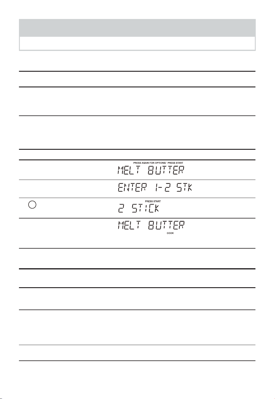
EN-64
NOTES
1. Cooking times are based on an average 8 ounce potato.
Baked Potato chart
FOOD AMOUNT PROCEDURE
Potato 1-4 servings Pierce with fork in several places. Place
on a paper towel on the turntable. After
cooking, remove from oven and let stand
for 5 minutes.
Setting Melt/Soften
The oven uses low power to melt and soften items. See the following table.
• Suppose you want to melt 2 sticks of butter.
Touch: Display Shows:
1.
"Melt/Soften"
2.
"Start/Enter/+30 Sec"
3.
2
4.
"Start/Enter/+30 Sec"
Time counting down
Melt Table
CATEGORY AMOUNT NUMBER
KEY
DIRECTION
MELT BUTTER 1 or 2 sticks
1, 2
Unwrap and place in microwavable
container. No need to cover butter. Stir at
the end of cooking to complete melting.
MELT
CHOCOLATE
2, 4 or 8 oz.
2, 4, 8
Chocolate chips or squares of baking
choco-late may be used. Unwrap squares
and place in microwavable container.
Stir at the end of cooking to complete
melting.
SOFTEN ICE
CREAM
Pint, 1.5
Quart.
1, 2
Place container in oven. lcecream will be
soft enough to make scooping easier.
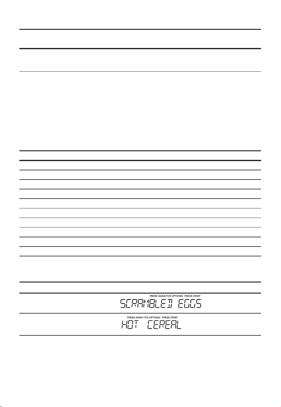
EN-65
CATEGORY AMOUNT NUMBER
KEY
DIRECTION
SOFTEN CREAM
CHEESE
3 or 8 oz.
3, 8
Unwrap and place in microwavable
contai-ner. Cream cheese will be at room
tempera-ture and ready for use in recipe.
AUTO COOKING
Auto Cook
Auto cook is divided into 2 parts-Quick Meals (Scrambled Eggs, Hot Cereal, Frozen Pizza,
Fudge Brownies) and Dinner Recipes (Garlic Shrimp, Asiago Red Potatoes, Roasted
Vegetable Medley, Lemon and Shrimp Risotto, White Chicken Chili).
Key Food Amount
Auto Cook x1 Scrambled Eggs 1 - 6 Eggs
Auto Cook x2 Hot Cereal 1 - 3 Servings
Auto Cook x3 Frozen Pizza 12 oz
Auto Cook x4 Fudge Brownies 18-19 oz
Auto Cook x5 Garlic Shrimp Per Recipe
Auto Cook x6 Stuffed Mushrooms Per Recipe
Auto Cook x7 Asiago Red Potatoes Per Recipe
Auto Cook x8 Roasted Vegetable Medley Per Recipe
Auto Cook x9 Lemon Shrimp Risotto Per Recipe
Auto Cook x10 White Chicken Chili Per Recipe
Quick Meals
• Suppose you want to cook Hot Cereal for 3 serving
Touch: Display Shows:
1.
"Auto Cook"
2.
"Auto Cook"
MELT TABLE
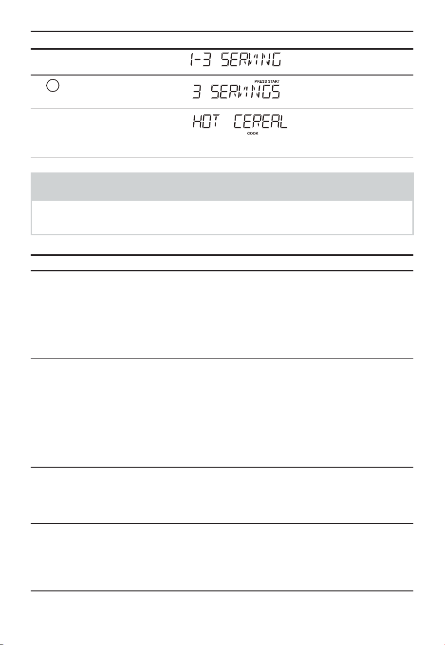
EN-66
Touch: Display Shows:
3.
"Start/Enter/+30 Sec"
4.
3
5.
"Start/Enter/+30 Sec"
Time counting down
NOTES
When "AUTO COOKING" selected, Turntable On is automatically set for
optimal cooking.
Quick Meals chart
FOOD AMOUNT PROCEDURE
1. Scrambled Eggs 1 - 6 eggs Whisk together egg and milk (use
1/2 tablespoon milk for each egg) in
a microwave safe bowl that has been
coated with cooking spray. Select
"Scrambled Eggs" under the Auto Cook
menu and the desired number of eggs to
be cooked. Stir half way through cooking
time.
2. Hot Cereal 1- 3 servings Use individual packets or bulk cereal in
your favorite variety: oatmeal, oat bran,
cream of wheat, farina or wheaten. Follow
package directions for the correct amount
of water or milk. To prevent boilovers,
it is very important to choose a large
container because microwave cooking
of cereal causes high boiling. Select "Hot
Cereal" under the Auto Cook menu and
the desired number servings.
3. Frozen Pizza* 12 oz Use for frozen microwave pizza. Remove
from package and unwrap. Follow
package directions for use of package
and/or silver crisping disk.
4. Fudge Brownies* 18-19 oz Prepare brownie mix according to
package directions. Spoon batter into
an 8 x 8 inch micro-wave safe glass dish
that has been coated with cooking spray.
Select "Fudge Brownies" under the Auto
Cook menu.
For the menus with *, please skip the step 3 and step 4.

EN-67
Dinner Recipes
• Suppose you want to cook Garlic shrimp.
Touch: Display Shows:
1.
"Auto Cook"
2.
"Auto Cook"
3.
"Auto Cook"
4.
"Auto Cook"
5.
"Auto Cook"
6.
"Start/Enter/+30 Sec"
Time counting down
Dinner Recipes
Garlic Shrimp
¼ cup butter
6 cloves garlic, minced
2 tablespoons chopped fresh chives
2 tablespoons lemon juice
1 tablespoon chili pepper paste
Salt to taste
1 pound raw, peeled and deveined large shrimp
Place butter in a 2 quart microwave safe casserole dish with lid. Microwave on High
power for 1 minute or until butter is melted. Stir in garlic, and microwave for an additional
1 minute. Stir in chives, lemon juice, chili pepper paste, and salt. Add shrimp, tossing
to coat evenly. Cover, and microwave on High power for 5 minutes, or until shrimp is
opaque, stirring after 3 minutes. Serve over hot cooked rice if desired.

EN-68
Stuffed Mushrooms
1 pound whole baby bella mushrooms
2 tablespoons butter, melted
1 bunch green onion, chopped
¼ cup shredded Parmesan cheese
2 tablespoons bread crumbs
1 teaspoon lemon juice
¼ teaspoon garlic pepper
Crushed red pepper to taste
Remove stems from mushrooms and set aside. Arrange mushroom caps on microwave
safe plate. Finely chop reserved mushroom stems. Combine butter, chopped mushroom
stems, and green onion in a 1 quart microwave safe dish; microwave on High power for
2 minutes. Add remaining ingredients and mix well. Spoon stuffing into mushroom caps.
Microwave on High power for 4 to 5 minutes, or until mushrooms are tender.
Asiago Red Potatoes
1 ¼ pound red potatoes, peeled and thinly sliced
2 tablespoons all purpose flour
½ teaspoon salt
1 ¼ cups milk
1 tablespoon butter, melted
5 ounces shredded Asiago cheese
Combine potatoes, flour, and salt in a zip top plastic bag; seal bag and shake to coat
potatoes. Transfer potatoes to a lightly greased 2 quart microwave safe casserole dish.
Add milk and butter, stirring well. Cover and microwave on 80% power for 12 minutes
or until potatoes are tender; sprinkle with cheese and microwave on 80% power for an
additional minute or until cheese melts.
Roasted Vegetables Medley
1 cup baby carrots
1 cup sliced yellow squash
1 cup sliced zucchini
½ cup sliced red bell pepper
½ cup thinly sliced onion
1 tablespoon butter
Garlic and herb seasoning to taste
Combine carrots, squash, zucchini, bell pepper, and onion in a 2 quart microwave safe
casserole dish. Dot with butter and sprinkle with seasoning. Cover, and microwave on
High power for 8 minutes or to desired degree of doneness.

EN-69
Lemon and Shrimp Risotto
2 teaspoons butter
2 teaspoons olive oil
2 tablespoons finely chopped shallot
4 cups chicken broth
¼ cup fresh squeezed lemon juice
2 cups risotto
1 pound medium shrimp, peeled and deveined
1 cup frozen peas, thawed
2 teaspoons grated lemon zest
¼ teaspoon black pepper
¾ teaspoon salt
Combine butter, olive oil, and shallot in a 1 quart microwave safe dish. Microwave on High
for 1 minute or until shallot is tender. Set aside.
Combine chicken broth and lemon juice in a 2 quart microwave safe measuring cup or
casserole dish. Cover with lid or vented plastic wrap. Microwave on High power for 10
minutes. Stir in reserved shallot mixture and risotto. Cover and continue to microwave
on 50% power for 20 minutes. Stir in shrimp, peas, grated lemon zest, pepper, and salt.
Cover and microwave on 50% power for 5 minutes or until shrimp is opaque.
White Chicken Chili
1 pound boneless, skinless chicken breast, cubed
½ cup chopped onion
3 garlic cloves, minced
1 (15 ounce) can white beans, drained
1 (4 ounce) can chopped green chili pepper
1 cup chicken broth
1 ½ teaspoon chili powder
¾ teaspoon cumin
½ teaspoon salt
½ teaspoon black pepper
½ cup chopped fresh cilantro
2 tablespoons fresh lime juice
Combine chicken, onion, and garlic in a 2.5 quart microwave safe dish. Cover, and
microwave on High for 6 minutes, or until chicken is fully cooked and onion is tender,
stirring after 3 minutes.
Add white beans, chili pepper, chicken broth, chili powder, cumin, salt and pepper,
stirring well. Cover and microwave on High for 10 minutes, stirring after 5 minutes.
Stir in cilantro and lime juice before serving.
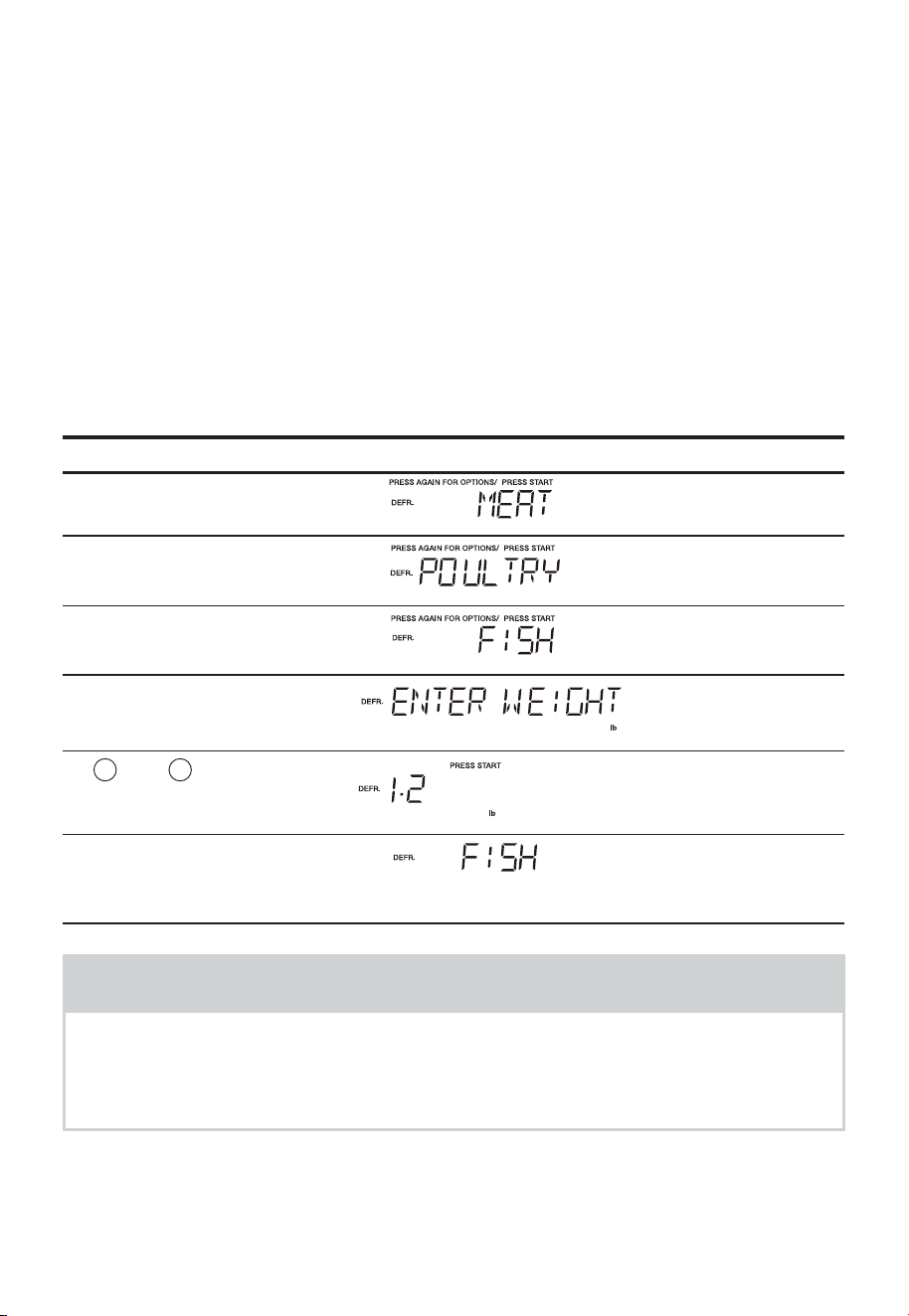
EN-70
AUTO DEFROST
Using Auto Defrost
The auto defrost feature provides you with the best defrosting method for frozen foods.
The cooking guide will show you which defrost sequence is recommended for the food
you are defrosting.
For added convenience, the Auto Defrost includes a built-in beep mechanism that
reminds you to check, turn over, separate, or rearrange the food in order to get the best
defrost results. Three different defrosting levels are provided:
1. MEAT
2. POULTRY
3. FISH
Available weight is 0.1-6.0 lbs
• Suppose you want to defrost 1.2 lbs of fish.
Touch: Display Shows:
1.
"Auto Defrost"
2.
"Auto Defrost"
3.
"Auto Defrost"
4.
"Start/Enter/+30 Sec"
5.
1
and
2
To enter weight
6.
"Start/Enter/+30 Sec"
COOK
Time counting down
NOTES
The oven will beep during the"DEFROST" cycle. At this time, open the door
and turn, separate, or rearrange the food. Remove any portions that have
thawed. Return frozen portions to the oven and touch "Start/Enter/+30 Sec"
to resume the defrost cycle.
EN-71
Operating Tips
• For best results, remove fish, shell fish, meat and poultry from its original closed paper
or plastic package (wrapper). Otherwise, the wrap will hold steam and juice close to the
foods, which can cause the outer surface of the food to cook.
• For best results, roll your ground meat into a ball before freezing. During the DEFROST
cycle, the microwave will signal when it is time to turn the meat over. Scrape off any
excess frost from the meat and continue defrosting.
• Place foods in a shallow container or on a microwave roasting rack to catch drippings.
This table shows food type selections and the weights you can set for each type. For
best results, loosen or remove covering on food.
KEY PRESS Category WEIGHTS YOU CAN SET
(tenths of a pound)
Auto Defrost x 1 Meat 0.1 to 6.0 lbs
Auto Defrost x 2 Poultry 0.1 to 6.0 lbs
Auto Defrost x 3 Fish 0.1 to 6.0 lbs
Weight conversion table
You are probably used to measuring food in pounds and ounces that are fractions of a
pound (for example, 4 ounces equals 1/4 pound). However, in order to enter the weight
of food in Auto Defrost, you must specify pounds and tenths of a pound. If the weight on
the food package is in fractions of a pound, you can use the following table to convert
the weight to decimals.
Equivalent Weight
OUNCES DECIMAL WEIGHT
1.6 .10
3.2 .20
4.0 .25 One-Quarter Pound
4.8 .30
6.4 .40
8.0 .50 One-Half Pound
9.6 .60
11.2 .70
12.0 .75 Three-Quarters Pound
12.8 .80
14.4 .90
16.0 1.0 One Pound
NOTES
If the weight is between two decimals, round down to the lower weight for
best defrosting results.
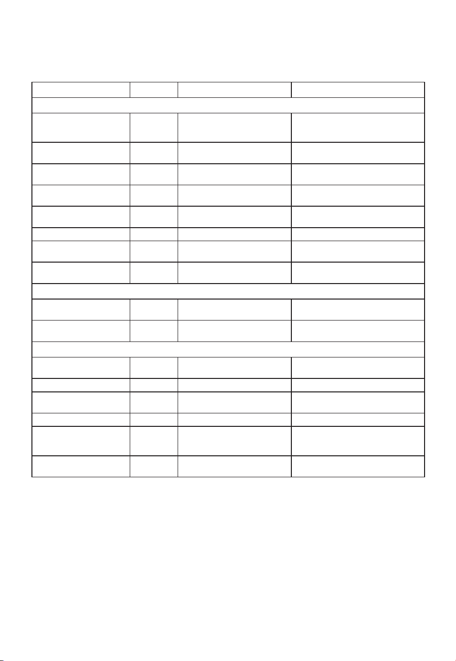
EN-72
Auto Defrost Table
NOTE:
Large, fatty pieces of meat or meat in irregular shapes, should have the
narrow or fatty areas shielded at the beginning of the defrost sequence.
Meat Settings
FOOD SETTING AT BEEP SPECIAL INSTRUCTIONS
BEEF
Ground Beef, Bulk MEAT Remove thawed portions
with fork. Turn over. Return
remainder to oven.
Do not defrost less than 1/4 lb. Freeze
in ball shape.
Ground Beef, Patties MEAT Separate and rearrange. Do not defrost less than 2 oz. patties.
Depress center when freezing.
Round Steak MEAT Turn over. Cover warm areas
with aluminum foil.
Place in a microwave safe dish.
Tenderloin Steak MEAT Turn over. Cover warm areas
with aluminum foil.
Place in a microwave safe dish.
Stew Beef MEAT Remove thawed portions with
fork. Separate remainder.
Place in a microwave safe dish.
Pot Roast, Chuck Roast MEAT Return remainder to oven. Place in a microwave safe dish.
Rib Roast MEAT Turn over. Cover warm areas
with aluminum foil.
Place in a microwave safe dish.
Rolled Rump Roast MEAT Turn over. Cover warm areas
with aluminum foil.
Place in a microwave safe dish.
LAMB
Cubes for Stew MEAT Turn over. Cover warm areas
with aluminum foil.
Place in a microwave safe dish.
Chops
(1 inch thick)
MEAT Remove thawed portions with
fork. Return remainder to oven.
Place in a microwave safe dish.
PORK
Chops
(1/2 inch thick)
MEAT Separate and rearrange. Place in a microwave safe dish.
Hot Dogs MEAT Separate and rearrange. Place in a microwave safe dish.
Spareribs Country-style
Ribs
MEAT Turn over. Cover warm areas
with aluminum foil.
Place in a microwave safe dish.
Sausage, Links MEAT Separate and rearrange. Place in a microwave safe dish.
Sausage, Bulk MEAT Remove thawed portions
with fork. Turn over. Return
remainder to oven.
Place in a microwave safe dish.
Loin Roast, Boneless MEAT Turn over. Cover warm areas
with aluminum foil.
Place in a microwave safe dish.

EN-73
Auto Defrost Table (Continued)
Poultry Settings
FOOD SETTING AT BEEP SPECIAL INSTRUCTIONS
CHICKEN
Whole
(up to 6 lbs)
POULTRY Turn over breast side down.
Cover warm areas with
aluminum foil.
Place chicken breast-side up in a
microwave safe dish. Finish defro
sting by immersing in cold water.
Remove giblets when chicken is
partially-defrosted.
Cut-up Separate pieces and rearrange.
Turn over. Cover warm areas
with aluminum foil.
Place in a microwave safe dish.
Finish defrosting by immersing in
cold water.
CORNISH
HENS
Whole
POULTRY Turn over. Cover warm areas
with aluminum foil.
Place in a microwave safe dish.
Finish defrosting by immersing in
cold water.
TURKEY
Breast
(up to 6 lbs)
POULTRY Turn over. Cover warm areas
with aluminum foil.
Place in a microwave safe dish.
Finish defrosting by immersing in
cold water.
Fish Settings
FOOD SETTING AT BEEP SPECIAL INSTRUCTIONS
FISH
Fillets FISH Turn over. Separate
fillets when partially
thawed, if possible.
Place in a microwave safe dish.
Carefully separate fillets under cold
water.
Steaks FISH Separate and
rearrange.
Place in a microwave safe dish. Run
cold water over to finish defrosting.
Whole FISH Turn over Place in a microwave safe dish. Cover
head and tail with foil; do not let
foil touch sides of microwave. Finish
defrosting by immersing in cold water.
SHELLFISH
Crab meat FISH Break apart. Turn over. Place in a microwave safe dish.
Lobster tails FISH Break apart. Turn over. Place in a microwave safe dish.
Shrimp FISH Break apart. Turn over. Place in a microwave safe dish.
Scallops FISH Break apart. Turn over. Place in a microwave safe dish.

EN-74
Defrosting Tips
• When using Auto Defrost, the weight to be entered is the net weight in pounds and
tenths of pounds (the weight of the food minus the container).
• Before starting, make sure to remove any and all metal twist-ties that often come with
frozen food bags, and replace them with strings or elastic bands.
• Open containers, such as cartons, before placing them in the oven.
• Always slit or pierce plastic pouches or packaging.
• If food is foil wrapped, remove foil and place food in a suitable container.
• Slit the skin of skinned food, such as sausage.
• Bend plastic pouches of food to ensure even defrosting.
• Always underestimate defrosting time. If defrosted food is still icy in the center, return
it to the microwave oven for more defrosting.
• The length of defrosting time varies according to how solidly the food is frozen.
• The shape of the package effects how quickly food will defrost. Shallow packages will
defrost more quickly than a deep container.
• As food begins to defrost, separate the pieces. change more easily to quicker.
• Use small pieces of aluminum foil to shield parts of food such as chicken wings, leg
tips, fish tails, or areas that start to get warm. Make sure the foil does not touch the
sides, top, or bottom of the oven. The foil can damage the oven lining.
• For better results, let food stand after defrosting.
• Turn over food during defrosting or standing time.
• Break apart and remove food as required.
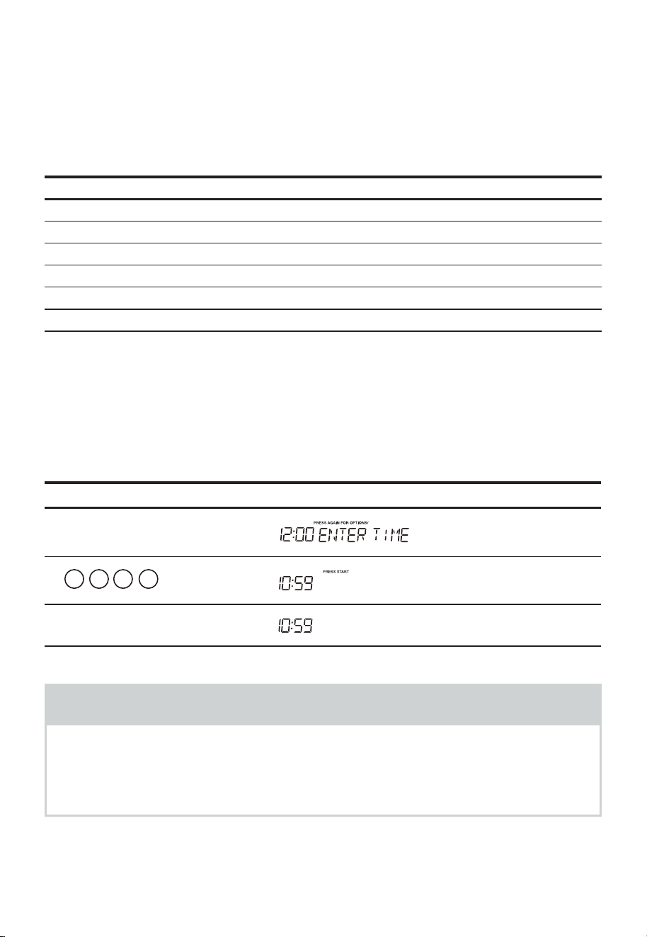
EN-75
CONVENIENT FEATURES
1. User pref
The microwave oven has settings that allow you to customize the operation for your
convenience. Below is the table showing the various settings. Touch the User pref key
multiple times to scroll to the desired setting function.
Key press Option
User pref X 1 Clock
User pref X 2 Control Lock
User pref X 3 Volume (Off/Low/Med/High)
User pref X 4 Weight (lb/kg)
User pref X 5 Clock dispiay
User pref X 6 Demo
(1). Setting Clock
The clock can be disabled when the microwave is first plugged in and the
"Stop/Clear" key is selected.
To re-enable the clock follow clock instructions.
• Suppose you want to set the clock for 10:59.
Touch: Display Shows:
1.
"User Pref"
2.
1 0 5 9
3.
"Start/Enter/+30 Sec"
NOTES
1. If you begin to enter in an incorrect time (e.g. 2:89) the 8 is an invalid digit and
cannot be entered.
Enter the correct time.
2. If you touch "Stop/Clear" while setting the clock, the display will show the last time
of day set or a blank display if no time of day has been set.
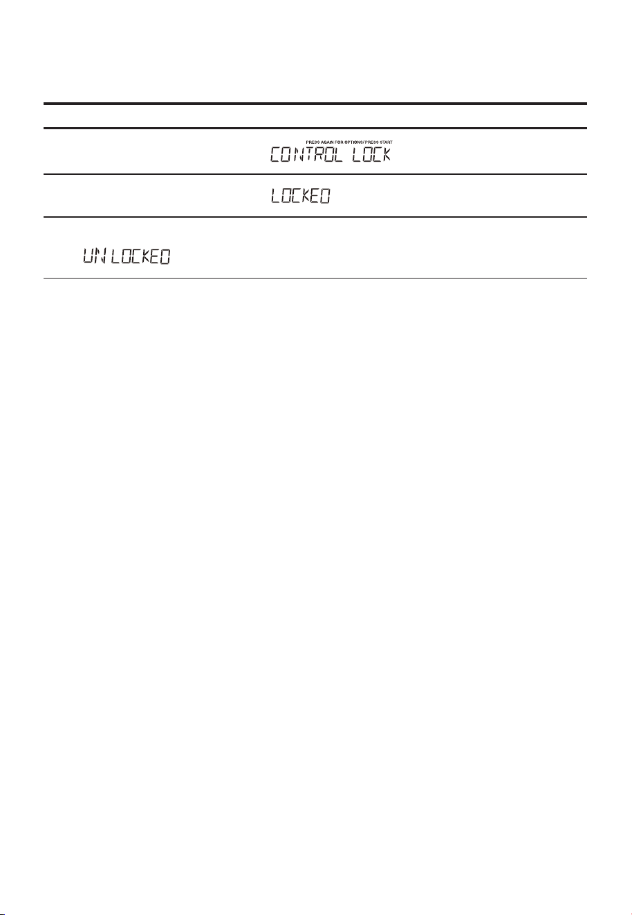
EN-76
(2). Setting Control Lock On/Off
To turn ON Control Lock.
Touch: Display Shows:
1.
"User Pref" X 2
2.
"Start/Enter/+30 Sec"
To turn OFF the Control Lock, touch User pref then touch "Start/Enter/+30
Sec"
will display.
,
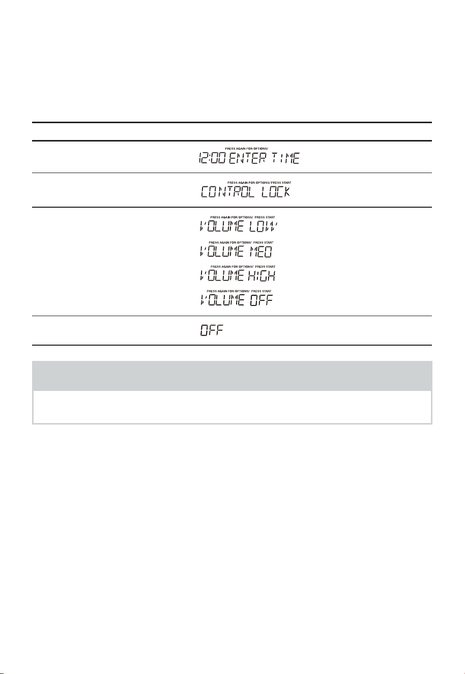
EN-77
(3). Turning Sound Low/Med/High/Off
Audible signals are available to guide you when setting and using your oven.
• A programming tone will sound each time you touch a button.
• Three tones signal the end of a Kitchen Timer count down.
• Three tones signal the end of a cooking cycle.
• Suppose you want to turn the audible signal off.
Touch: Display Shows:
1.
"User Pref"
2.
"User Pref"
3.
"User Pref"
4.
"Start/Enter/+30 Sec"
NOTES
When the cooking cycle is completed END will be displayed and the audible signal
will sound if the sound is turned on.

EN-78
(4). Setting Weight Lb/ Kg
• Suppose you want to toggle weight between pounds & kilograms.
Touch: Display Shows:
1.
"User Pref"
2.
"User Pref"
3.
"User Pref"
4.
"User Pref"
5
. "Start/Enter/+30 Sec"
kg
Ib
or
NOTES
If the display shows kg, pressing the "Start/Enter/+30 Sec" button will reset the oven
controls to lbs. To return to kg, you will have to press "User Pref" four times and then
press "Start/Enter/+30 Sec".
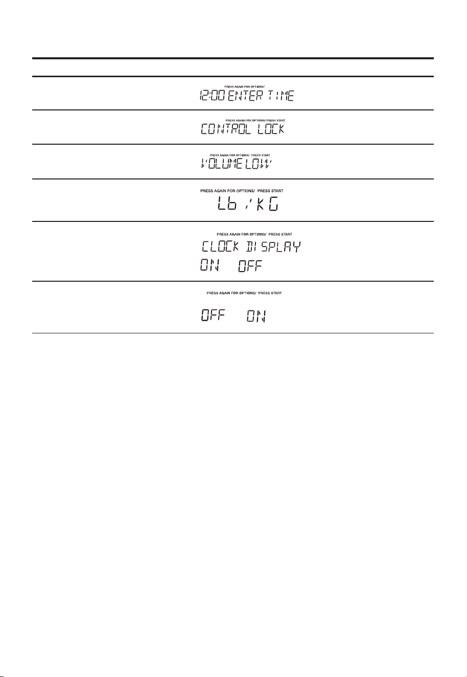
EN-79
(5). Setting Clock Display
• Suppose you want to set the clock display.
Touch: Display Shows:
1.
"User Pref"
2.
"User Pref"
3.
"User Pref"
4.
"User Pref"
5
. "User Pref"
or
6.
"Start/Enter/+30 Sec"
or
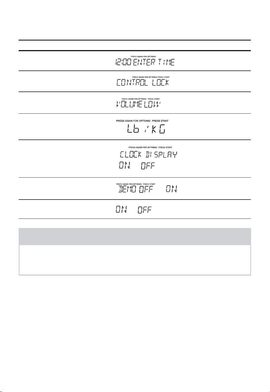
EN-80
(6). Setting Demo Mode On/Of
• Suppose you want to enter Demo mode. When Demo mode is ON programming
functions will work in a rapid countdown mode with no cooking power.
Touch: Display Shows:
1.
"User Pref"
2.
"User Pref"
3.
"User Pref"
4.
"User Pref"
5
. "User Pref"
6.
"User Pref"
or
7.
"Start/Enter/+30 Sec"
or
NOTES
When "Start/Enter/+30 Sec" is pressed and the previous setting was OFF then it will
be set to ON. If you want to turn the demo mode back OFF you will have to again
press User pref six times and then press "Start/Enter/+30 Sec".
or
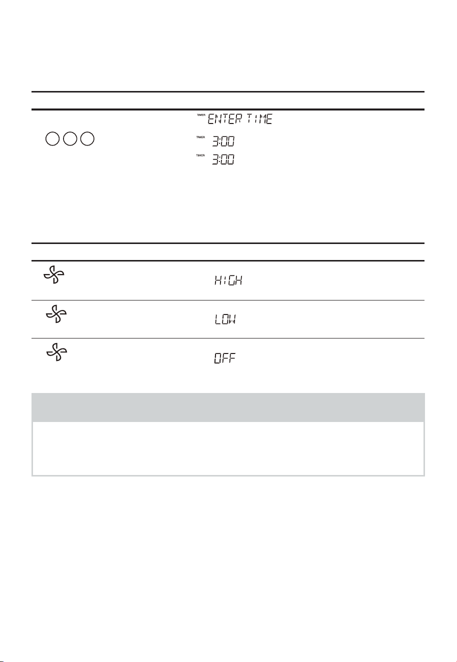
EN-81
2. Setting Kitchen Timer
Your microwave oven can be used as a kitchen timer. You can set up to 99 minutes, 99
seconds.
The kitchen timer can be used while the microwave oven is running.
• To set the timer for three minutes.
Touch: Display Shows:
1.
"Timer"
2.
03 0
3.
"Timer"
Timer starts counting down
3. Using Vent Fan
The vent button controls the fan, which has 2-speeds. If the vent fan is off, the first press
of the button will set the fan to High, second touch will be LOW and third will be OFF.
Touch: Display Shows:
1.
2.
3.
NOTES
If the temperature from the range or cooktop below the oven gets too hot, the vent
fan will automatically turn on to protect the oven.
It may stay on up to an hour to cool the oven.
When this occurs, the Vent button will not turn the fan off.
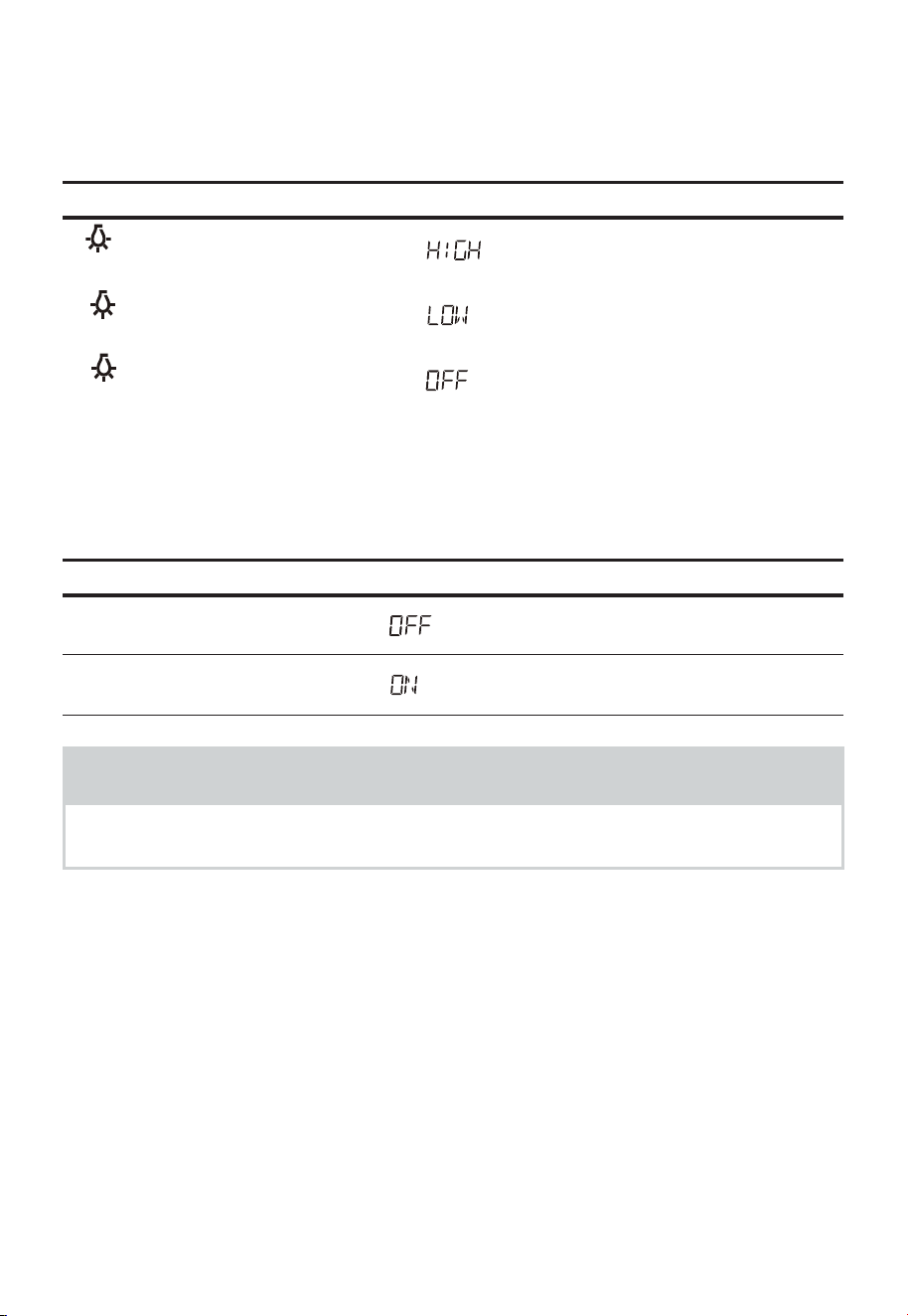
EN-82
4. Using Cooktop Light
The light icon button controls the cooktop light. If the light is OFF the first touch of the
light button will turn the light ON (high), second touch will reduce the power of the light
to Low and third touch will be OFF.
Touch: Display Shows:
1.
2.
3.
5. Setting Turntable On/Off
Press Turntable On-Off to turn the turntable on or off.
For best cooking results, leave the turntable on. It can be turned off for large dishes.
Touch: Display Shows:
1. "Turntable On-Off"
2.
"Turntable On-Off"
NOTES
Sometimes the turntable can become hot to the touch during and after cooking. Do
not run the oven empty without food in it.

EN-83
TROUBLESHOOTING
Check your problem by using the chart below and try the solutions for each problem. If
the microwave oven still does not work properly, contact the nearest authorized service
center.
TROUBLE POSSIBLE CAUSE POSSIBLE REMEDY
Oven will not start
• Electrical cord for oven is not
plugged in.
• Door is open.
• Wrong operation is set.
• Plug into the outlet.
• Close the door and try
again.
• Check instructions.
Arcing or sparking
• Materials to be avoided in
microwave oven were used.
• The oven is operated when
empty.
• Spilled food remains in the
cavity.
• Use microwave-safe
cookware only.
• Do not operate with oven
empty.
• Clean cavity with wet towel.
Unevenly cooked foods
• Materials to be avoided in
microwave oven were used.
• Food is not defrosted
completely.
• Cooking time, power level is
not suitable.
• Food is not turned or stirred.
• Use microwave-safe
cookware only.
• Completely defrost food.
• Use correct cooking time,
power level.
• Turn or stir food.
Overcooked foods
• Cooking time, power level is
not suitable.
• Use correct cooking time,
power level.
Undercooked foods
• Materials to be avoided in
microwave oven were used.
• Food is not defrosted
completely.
• Oven ventilation ports are
restricted.
• Cooking time, power level is
not suitable.
• Use microwave-safe
cookware only.
• Completely defrost food.
• Check to see that oven
ventilation ports are not
restricted.
• Use correct cooking time,
power level.
Improper defrosting
• Materials to be avoided in
microwave oven were used.
• Cooking time, power level is
not suitable.
• Food is not turned or stirred.
• Use microwave-safe
cookware only.
• Use correct cooking time,
power level.
• Turn or stir food.

EN-84
TRADEMARKS, COPYRIGHTS AND
LEGAL STATEMENT
logo, word marks, trade name, trade dress and all versions thereof are valuable
assets of Midea Group and/or its affiliates ("Midea"). to which Midea owns trademarks,
copyrights and other intellectual property rights, and all goodwill derived from using any
part of an Midea trademark. Use of Midea trademark for commercial purposes without
the prior written consent of Midea may constitute trademark infringement or unfair
competition in violation of relevant laws.
This manual is created by Midea and Midea reserves all copyrights thereof. No entity or
individual may use, duplicate, modify, distribute in whole or in part this manual, or bundle
or sell with other products without the prior written consent of Midea.
All the described functions and instructions were up to date at the time of printing this
manual. However, the actual product may vary due to improved functions and designs.

EN-85
DATA PROTECTION NOTICE
For the provision of the services agreed with the customer,
we agree to comply without restriction with all stipulations of applicable data protection
law, in line with agreed countries within which services to the customer will be delivered.
Generally, our data processing is to fulfil our obligation under contract with you and for
product safety reasons, to safeguard your rights in connection with warranty and product
registration questions. In some cases, but only if appropriate data protection is ensured,
personal data might be transferred to recipients located outside of the European
Economic Area.
Further information are provided on request. You can contact our Data Protection Officer
via [email protected]om. To exercise your rights such as right to object your personal
date being processed for direct marketing purposes, please contact us via MideaDPO@
midea.com. To find further information, please follow the QR Code.


www.midea.com
© Midea 2022 all rights reserved
MANUEL D’UTILISATION
Avertissements: Avant d’utiliser ce produit, veuillez lire attentivement ce manuel et le garder pour une
référence future.
La conception et les spécifications peuvent être modifiées sans préavis pour améliorer le produit. Consultez
votre revendeur ou votre fabricant pour en savoir plus.
Le schéma ci-dessus est fourni à titre indicatif. Considérez l'apparence du produit réel comme référence.
MMO19S14ASTC
Four à micro-ondes domestique

FR-01
LETTRE DE REMERCIEMENT -----------------------------------FR-01
CONSIGNES DE SÉCURITÉ --------------------------------------FR-02
CARACTÉRISTIQUES ---------------------------------------------FR-11
APERÇU DU PRODUIT -------------------------------------------FR-12
INSTALLATION DU PRODUIT -----------------------------------FR-13
CONSIGNES D’UTILISATION ------------------------------------FR-51
DÉPANNAGE ------------------------------------------------------FR-83
MARQUES COMMERCIALES, DROITS D'AUTEUR ET
MENTIONS LÉGALES --------------------------------------------FR-84
AVIS SUR LA PROTECTION DES DONNÉES ------------------FR-85
SOMMAIRE
LETTRE DE REMERCIEMENT
Merci d'avoir choisi Midea! Avant d'utiliser votre nouveau produit Midea, veuillez
lire attentivement ce manuel pour vous assurer que vous savez comment utiliser
les caractéristiques et fonctions offertes par votre nouvel appareil en toute
sécurité.
FR-02
CONSIGNES DE SÉCURITÉ
Utilisation prévue
Les consignes de sécurité suivantes sont destinées à prévenir les risques ou les
dommages imprévus dus à une utilisation dangereuses ou incorrecte de l'appareil.
Veuillez vérifier l'emballage et l'appareil à l'arrivée pour vous assurer que tout est intact
afin de garantir un fonctionnement sûr. Si vous constatez des dommages, veuillez
contacter le détaillant ou le revendeur. Veuillez noter que les modifications ou altérations
de l’appareil ne sont pas autorisées pour des raisons de sécurité. L’utilisation non prévue
peut entraîner des dangers et la perte de réclamations de garantie.
Explication des symboles
Danger
Ce symbole indique que les gaz extrêmement inflammables présentent des
dangers pour la vie et la santé des personnes.
Avertissement relatif à la tension électrique
Ce symbole indique qu'il existe un danger pour la vie et la santé des personnes à
cause de la tension.
Avertissement
La mention d'avertissement indiqu'un danger présentant un niveau de risque
moyen qui, s'il n'est pas évité, peut entraîner la mort ou des blessures graves.
Mise en garde
La mention d'avertissement indiqu'un danger à faible risque qui, s'il n'est pas
évité, peut entraîner des blessures légères ou modérées.
Attention
La mention d'avertissement indique des informations importantes (p. ex. un
dommage matériel), mais pas de danger.
Respectez les instructions
Ce symbole indique qu'un technicien d'entretien ne doit utiliser et entretenir cet
appareil que conformément aux consignes d'utilisation.
Lisez attentivement ces consignes d'utilisation avant d'utiliser/de mettre en service
l'appareil et le conserver à proximité immédiate du lieu d'installation ou de l'appareil pour
toute utilisation ultérieure.

FR-03
PRÉCAUTIONS POUR ÉVITER
UNE POSSIBLE EXPOSITION À
UNE ÉNERGIE EXCESSIVE DES
MICRO-ONDES
a. N'essayez pas de faire fonctionner ce four avec la
porte ouverte, car cela peut entraîner une exposition
nocive à l'énergie des microondes.
Il est important de ne pas annuler ou altérer les
dispositifs de verrouillage de sécurité.
b. Ne pas placer un objet entre la face avant et la porte,
ou laisser de la saleté ou des résidus de nettoyage
s’accumuler sur les surfaces du joint.
c. N'utilisez pas le four s'il est endommagé. Il est
particulièrement important que la porte du four se
ferme correctement et qu'il n'y ait aucun dommage
aux:
-
PORTE (courbée)
-
CHARNIÈRES ET LOQUETS (cassés ou desserrés)
-
JOINTS DE PORTE ET SURFACE D'ÉTANCHÉITÉ
d. Le four ne doit pas être réglé ou réparé par
quelqu'un qui n'est pas un personnel de dépannage
qualifié.

FR-04
CONSIGNES DE SÉCURITÉ
IMPORTANTES
Lors de l’utilisation d’appareils électriques, des
précautions de sécurité de base doivent être
respectées, notamment les suivantes:
AVERTISSEMENT
Pour réduire les risques de brûlures, d’électrocution,
d’incendie, de blessures ou d’exposition à une énergie
micro-ondes excessive:
• Lisez toutes les instructions avant d'utiliser l'appareil.
• Lisez et suivez ces instructions: «PRÉCAUTIONS
POUR ÉVITER L'EXPOSITION POSSIBLE À L'ÉNERGIE
MICROONDE EXCESSIVE» à la page 03.
• Cet appareil doit être mis à la terre. Branchez
l'appareil uniquement à une prise correctement
mise à la terre. Voir «INSTRUCTIONS DE MISE À LA
TERRE» à la page 07.
• Installez ou placez ce four uniquement conformément
aux instructions d'installation fournies.
• Certains produits tels que les œufs entiers et les
récipients scellés — par exemple bocaux en verre
fermés — peuvent exploser et ne doivent pas être
chauffés dans un four à microondes.
• N'utilisez cet appareil que pour les utilisations prévues
décrites dans ce manuel. N'utilisez pas de produits
chimiques ou de vapeurs corrosifs dans cet appareil.
Ce four à microondes est spécialement conçu pour
chauffer, cuire ou sécher des aliments. Il n'est pas
conçu pour une utilisation industrielle ou en laboratoire.
• LES CONTENUS CHAUDS PEUVENT CAUSER DE
GRAVES BRÛLURES. NE PERMETTEZ PAS AUX
ENFANTS D'UTILISER LE MICRO-ONDES. Soyez
prudent lorsque vous retirez des articles chauds.

FR-05
• N'utilisez pas ce four si le cordon ou la fiche est
endommagé, s'il ne fonctionne pas correctement, s'il
est endommagé ou s'il est tombé.
• Cet appareil ne doit être entretenu que par du
personnel qualifié. Contactez le centre de service agréé
le plus proche pour examen, réparation ou réglage.
• Ne couvrez ni ne bloquez les ouvertures de l'appareil.
• Ne rangez pas cet appareil à l'extérieur. N'utilisez pas
ce four près de l'eau, par exemple près d'un évier de
cuisine, dans un sous-sol humide, près d'une piscine
ou dans des endroits similaires.
• N'immergez pas le cordon ou la fiche dans l'eau.
• Gardez le cordon éloigné des surfaces chaudes.
• Ne laissez pas le cordon pendre du bord d'une table
de travail ou d'un comptoir.
• Lors du nettoyage des surfaces de la porte et du four
qui advient en même temps à la fermeture de la porte,
utilisez uniquement des savons ou détergents doux non
abrasifs appliqués avec une éponge ou un chiffon doux.
• Pour réduire le risque d'incendie dans la cavité du four:
-
Ne faites pas trop cuire les aliments. Surveillez
attentivement l'appareil si vous avez placé un objet
en papier, plastique ou autre matériau combustible
dans la cavité pour faciliter la cuisson.
-
Retirez les attaches métalliques des sacs en papier
ou en plastique avant de les placer dans le four à
microondes.
-
Si des matériaux à l’intérieur du four à microondes
s’enflamment, gardez la porte fermée, éteignez le
four et débranchez le cordon d’alimentation ou
coupez l’alimentation au niveau du fusible ou du
panneau de disjoncteur.
-
N'utilisez pas la cavité à des fins de rangement. Ne
laissez pas de produits en papier, d'ustensiles de
cuisine ou de nourriture dans la cavité lorsqu'elle
n'est pas utilisée.

FR-06
• Les liquides, tels que l’eau, du café ou du thé, peuvent
surchauffer au-delà du point d’ébullition sans avoir l’air
de bouillir. Un bouillonnement ou une ébullition visible
lorsque le récipient est retiré du four à micro-ondes
n'apparaît pas toujours.
CELA POURRAIT EN RÉSULTER DES LIQUIDES TRÈS
CHAUDS QUI DEVIENNENT SOUDAINEMENT EN
ÉBULLITION LORSQUE LE RÉCIPIENT EST PERTURBÉ
OU UN USTENSILE EST INSÉRÉ DANS LE LIQUIDE.
Pour réduire le risque de blessures aux personnes:
-
Ne surchauffez pas le liquide.
-
Remuez le liquide avant et à mi-cuisson.
-
N’utilisez pas de récipients à parois droites à col étroit.
-
Après chauffage, laissez le récipient reposer dans le
four à microondes pendant un court instant avant
de retirer le récipient.
-
Soyez extrêmement prudent lorsque vous insérez
une cuillère ou un autre ustensile dans le récipient.
• Les aliments et les ustensiles métalliques trop grands
ne doivent pas être introduits dans un four à micro-
ondes/grille-pain, car ils peuvent entraîner un risque
d'incendie ou d'électrocution.
• Ne nettoyez pas avec des tampons à récurer
métalliques. Des pièces peuvent brûler les tampons
et toucher les pièces électriques, entraînant un risque
de choc électrique.
• N'utilisez pas de produits en papier lorsque l'appareil
fonctionne en mode grille-pain.
• Ne rangez pas des objets autres que les accessoires
recommandés par le fabricant dans ce four lorsqu'il
n'est pas utilisé.
• Ne couvrez pas les grilles et toute autre partie
du four avec du papier d'aluminium. Cela peut
provoquer la surchauffe du four.
• Nettoyez fréquemment la hotte de ventilation - Ne
laissez pas la graisse s’accumuler sur la hotte ou le filtre.

FR-07
• Lorsque des aliments s’enflamment sous la hotte,
allumez le ventilateur.
• Faites attention lors du nettoyage du filtre de la
hotte. Les agents de nettoyage corrosifs, tels que la
soude, peuvent endommager le filtre.
• Il peut être utilisé avec des ustensiles de cuisson au
gaz et électriques.
CONSERVER LE PRÉSENTE
MANUEL
INSTRUCTIONS DE LA MISE À
LA TERRE
Cet appareil doit être mis à la terre. En cas de court-
circuit, la mise à la terre réduit le risque de décharge
électrique en fournissant un fil de fuite vers la terre. Cet
appareil est équipé avec un cordon ayant un conducteur
de mise à la terre. La fiche doit être branchée dans une
prise correctement installée et mise à la terre.
AVERTISSEMENT
Une mauvaise utilisation de la mise à la terre peut
entraîner un risque d'électrocution. Consulter un
électricien qualifié ou un réparateur si les instructions
de mise à la terre ne sont pas parfaitement comprises
ou si un doute existe sur la bonne mise à la terre de
l'appareil. S'il est nécessaire d'utiliser une rallonge,
utilisez uniquement une rallonge à 3fils dotée d'une
fiche de mise à la terre à 3broches et des prises à
3positions qui acceptent la fiche de l'appareil. La
puissance nominale de la rallonge doit être égale ou
supérieure à la puissance électrique de l'appareil.

FR-08
DANGER
Risque de choc électrique
Le fait de toucher à certains composants internes peut
provoquer des blessures graves voire mortelles. Ne pas
démonter cet appareil.
AVERTISSEMENT
Risque de choc électrique
La mauvaise utilisation de la mise à la terre peut
entraîner une décharge électrique. Ne pas brancher
à une prise de courant tant que l'appareil n'est pas
installé correctement et mis à la terre.
• Le fil d'alimentation est court pour réduire le risque de
le coincer ou de trébucher dessus s'il est plus long.
• Des jeux de cordons plus longs ou des rallonges
sont disponibles et peuvent être utilisés si un soin
particulier est apporté à leur utilisation.
• Si vous utilisez un long cordon ou une rallonge:
-
La capacité électrique du fil ou de la rallonge doit être
au moins aussi grande que la capacité de l'appareil.
-
La rallonge doit être à 3 fils avec une mise à la terre.
-
Un long fil d'alimentation doit être mis de façon à
ne pas dépasser du comptoir ou de la table d'où il
peut être tiré par des enfants ou faire trébucher.
INTERFÉRENCE RADIO
• Le fonctionnement du four à micro-ondes peut
provoquer des interférences avec votre radio,
télévision ou équipement similaire.
• Lorsqu'il y a des interférences, elles peuvent être
réduites ou éliminées en prenant les mesures suivantes:
-
Nettoyez la porte et les surfaces d’étanchéité du four
-
Réorientez l'antenne de réception de la radio ou du
téléviseur.
FR-09
-
Déplacez le four à microondes par rapport au récepteur.
-
Éloignez le four à microondes du récepteur.
-
Branchez le four à microondes dans une autre prise
de sorte qu'il se trouve avec le récepteur sur des
circuits de dérivation différents.
CET APPAREIL EST CONFORME
À LA PARTIE 18 DES RÈGLES DE
LA FCC.
USTENSILES
MISE EN GARDE
Danger exposant aux blessures corporelles
Les ustensiles hermétiquement fermés peuvent exploser.
Les récipients fermés doivent être ouverts et les sachets
en plastique doivent être percés avant la cuisson.
Voir les instructions dans «Matériaux que vous pouvez
utiliser dans le four à micro-ondes ou à éviter dans le
four à micro-ondes».
Il peut avoir certains ustensiles non métalliques qui ne
peuvent pas être utilisés en toute sécurité dans le four
à micro-ondes. En cas de doute, vous pouvez tester
l'ustensile en question en procédant de la façon suivante.
Test d'ustensile:
• Remplir un conteneur pour micro-ondes de 250ml
d'eau froide et y déposer l'ustensile.
• Chauffer à puissance max. pendant 1 minute.
• Toucher doucement l'ustensile. Si l'ustensile vide est
chaud, ne pas l'utiliser pour la cuisson au microonde.
• Ne pas dépasser 1 minute.
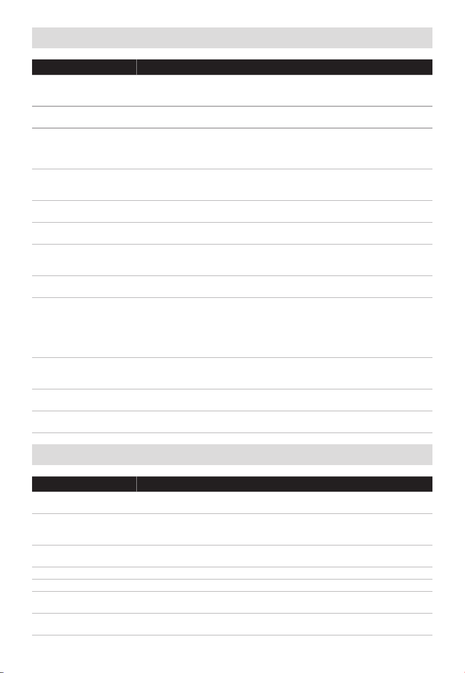
FR-10
Matériaux que vous pouvez utiliser dans un four à micro-ondes
Ustensiles Remarques
Plat à rôtir
Suivre les instructions du fabricant. Le fond du plat à brunir doit
être à au moins 3/16pouce (5mm) au-dessus du plateau tournant.
Un mauvais usage peut briser le plateau.
Vaisselle
Allant au four à micro-ondes uniquement. Suivez les consignes du
fabricant. N’utilisez pas de vaisselle fissurée ou ébréchée.
Pots en verre
Toujours retirer le couvercle. Utiliser uniquement jusqu'à ce que les
aliments soient chauds.
La plupart des pots ne résistent pas à la chaleur et peuvent se
briser.
Verrerie
Uniquement de la verrerie résistante à la chaleur du four. S'assurer
qu'il n'y a pas de garniture métallique. N’utilisez pas de vaisselle
fissurée ou ébréchée.
Sacs de cuisson pour
four
Suivre les instructions du fabricant. Ne pas fermer avec un couvercle
métallique. Fendre pour permettre à la vapeur de s'échapper.
Assiettes et tasses en
papier
N'utiliser que pour la cuisson ou réchauffage court. Ne pas laisser la
cuisson sans surveillance.
Serviettes en papier
Utiliser pour couvrir les aliments à réchauffer et absorber le
gras. Utiliser sous surveillance pour une cuisson de courte durée
uniquement.
Papier parchemin
Utiliser comme couvercle pour éviter les éclaboussures ou
envelopper pour cuire à la vapeur.
Plastique
Allant au four à micro-ondes uniquement. Suivre les instructions du
fabricant.
Doit être estampillé «Sûr pour le microonde». Certains conteneurs
en plastique s'amollissent quand les aliments deviennent chauds.
Les sacs à bouillir et les sacs en plastique fermés doivent être
fendus, percés ou ventilés comme indiqué sur l'emballage.
Enveloppe en
plastique
Allant au four à micro-ondes uniquement. Utiliser pour couvrir les
aliments pendant la cuisson pour retenir l'humidité. Ne laissez pas
l'emballage plastique toucher les aliments.
Thermomètres
Uniquement compatible avec les objets pouvant aller au micro-
ondes (thermomètres à viande ou gâteau).
Papier ciré
Utiliser comme couvercle pour éviter les éclaboussures ou retenir
l'humidité.
Matériaux à éviter dans le four à micro-ondes
Ustensiles Remarques
Plateau en aluminium
Peut provoquer un arc. Transférez les aliments dans un plat
compatible avec le four à micro-ondes.
Carton alimentaire
avec poignée
métallique
Peut provoquer un arc. Transférez les aliments dans un plat
compatible avec le four à micro-ondes.
Ustensiles en métal
ou garnis de métal
Le métal bloque les microondes sur les aliments. Les garnitures
métalliques provoquent les arcs.
Lien métalliques Peuvent provoquer un arc et entrainer un incendie dans le four.
Sacs en papier Peuvent prendre feu dans le four.
Mousse en plastique
La mousse en plastique peut fondre ou contaminer le liquide
contenu en l'exposant à de hautes températures.
Bois
Le bois sèche quand il est utilisé dans le microonde et peut se
fendre ou craquer.

FR-11
CARACTÉRISTIQUES
MODÈLE
Tension/Fréquence nominale 120VAC 60Hz
Puissance nominale d'entrée (Microondes) 1500 W
Puissance nominale de sortie (Microondes) 1000W
MMO19S14ASTC
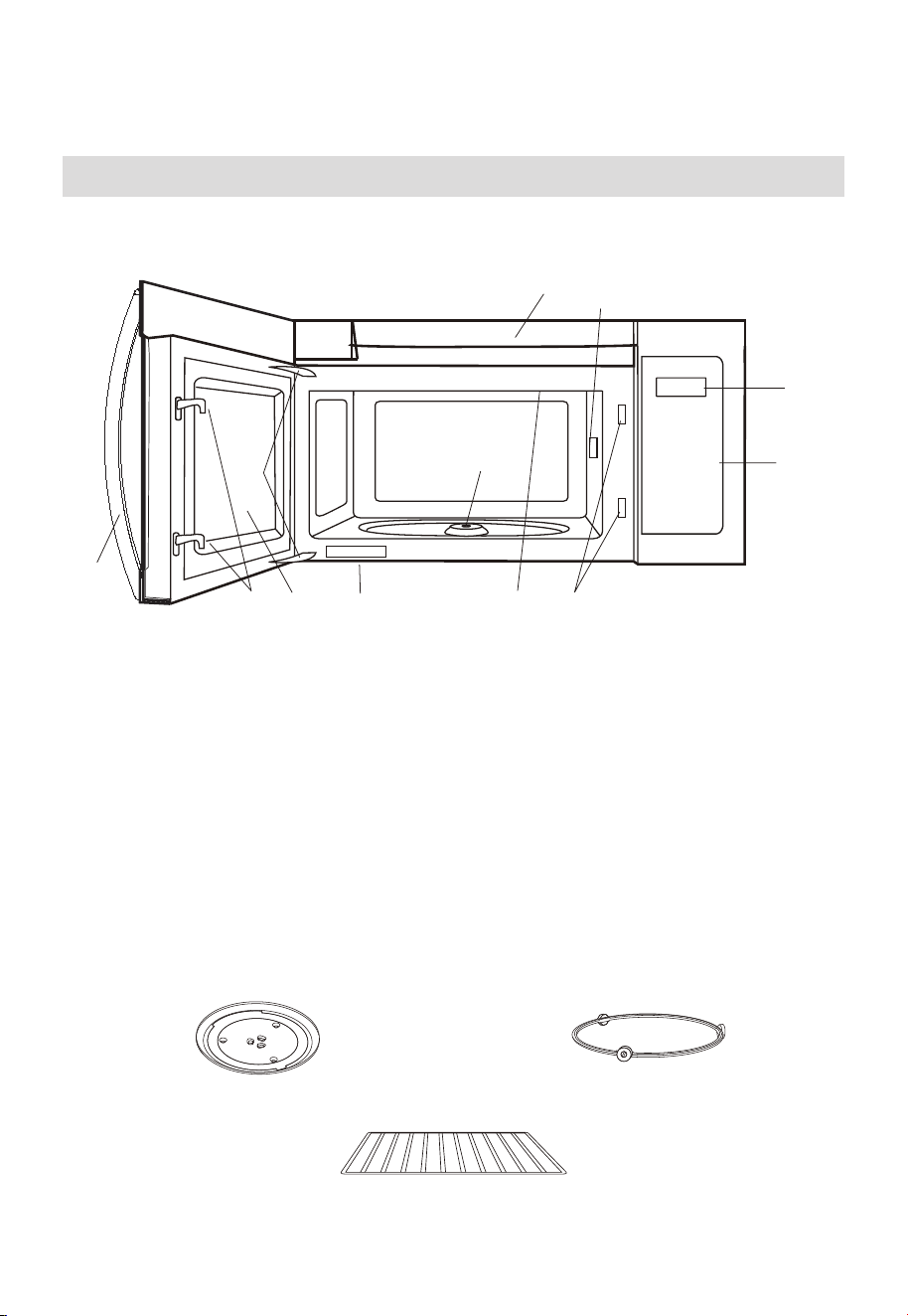
FR-12
APERÇU DU PRODUIT
Installation de votre four
NOMS DES PIÈCES
9
8
10
3
6
4
11
1
2
7
6
5
1. Porte du four à micro-ondes avec fenêtre transparente
2. Charnières de porte
3. Couvercle du guide d’ondes : NE PAS ENLEVER.
4. Arbre moteur du plateau tournant
5. Lumière du four à micro-ondes
Il s’allume lorsque le four à micro-ondes fonctionne ou que la porte est ouverte.
6. Verrous de sécurité de porte
Le four à micro-ondes ne fonctionne que si la porte est bien fermée.
7. Poignée
8. Panneau de commande
9. Écran
10. Ouvertures de ventilation
11. Étiquette de notation
Plateau tournant en verre Assemblage De L’Anneau Du Plateau Tournant
Grille pour cuisson/réchauffage à 2 niveaux
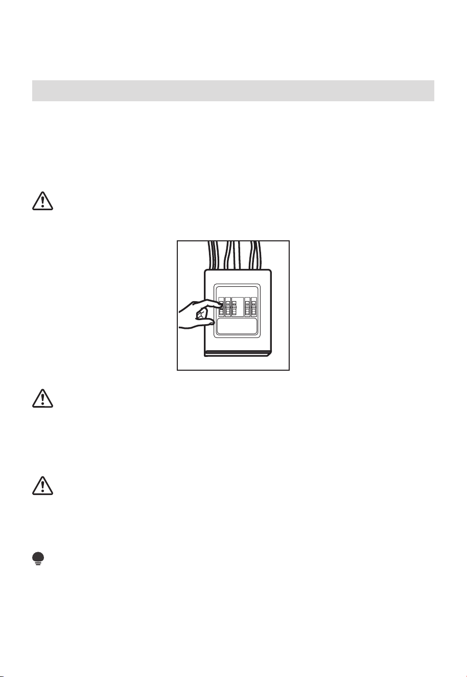
FR-13
INSTALLATION DU PRODUIT
CONSIGNES DE SÉCURITÉ IMPORTANTES
Ce produit nécessite une prise de courant à trois broches avec mise à la terre. L'installateur
doit vérifier la continuité de la mise à la terre du boîtier de prise de courant avant de
commencer l'installation afin de s'assurer que celui-ci est correctement mis à la terre. Si
la mise à la terre n'est pas correcte ou si la boîte de sortie ne répond pas aux exigences
électriques mentionnées (sous la rubrique EXIGENCES ÉLECTRIQUES), il convient de
faire appel à un électricien qualifié pour remédier à ces défauts.
MISE EN GARDE :
Pour votre sécurité personnelle, retirez le fusible de la maison ou désactivez le disjoncteur
avant de commencer l'installation pour éviter des blessures graves ou mortelles.
MISE EN GARDE :
Pour la sécurité personnelle, la surface de montage doit être capable de supporter la
charge de l'armoire, en plus du poids supplémentaire de ce produit de 63-85 livres
(28,5-38,5 kg), plus des charges de four supplémentaires allant jusqu'à 50 livres (22,7 kg)
ou un poids total de 113-135 livres (51,3-61,2 kg).
MISE EN GARDE :
Pour des raisons de sécurité personnelle, ce produit ne peut pas être installé dans des
armoires telles qu'une île ou une péninsule. Il doit être monté à la FOIS sur une armoire
supérieure ET sur un mur.
REMARQUE:
Pour faciliter l'installation et procurer la sécurité personnelle, il est recommandé que deux
personnes installent ce produit.
IMPORTANT – VEUILLEZ LIRE ATTENTIVEMENT. POUR VOTRE SÉCURITÉ
PERSONNELLE, CET APPAREIL DOIT ÊTRE CORRECTEMENT MIS À LA TERRE POUR
ÉVITER UN CHOC GRAVE OU MORTEL.
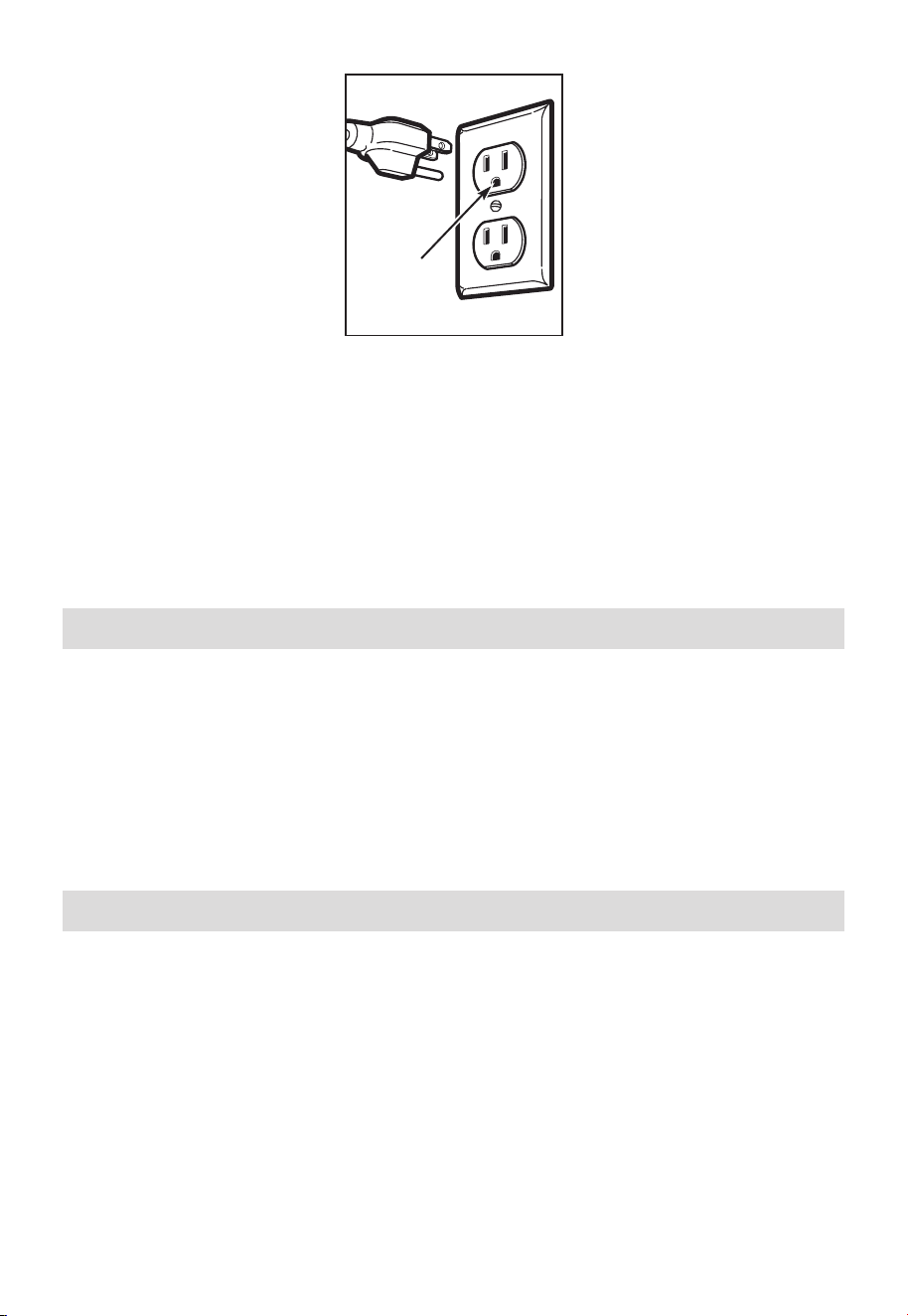
FR-14
Assurez-vous
que la mise à la
terre est correcte
avant l'utilisation
Le cordon d’alimentation de cet appareil est équipé d’une fiche à trois broches (mise à la
terre) qui s’adapte à une prise murale standard à trois broches également mise à la terre
afin de minimiser les risques de décharge électrique liés à cet appareil.
Vous devez faire vérifier la prise murale et le circuit par un électricien qualifié pour vous
assurer que la prise est correctement mise à la terre.
Lorsqu'une prise murale standard à deux fiches est présente, il est très important de la
faire remplacer par une prise murale à trois fiches correctement mise à la terre, installée
par un électricien qualifié.
NE JAMAIS, SOUS AUCUN PRÉTEXTE, COUPER, DÉFORMER OU RETIRER L'UNE DES
BROCHES DU CORDON D'ALIMENTATION. NE L’UTILISEZ PAS AVEC UNE RALLONGE.
Exigences électriques
La puissance nominale du produit est de 120 V~ 60 Hz, 15 ampères et 1,6 kilowatts. Ce
produit doit être connecté à un circuit d'alimentation séparé et dédié, de tension et de
fréquence appropriées. La taille des câbles doit être conforme aux exigences du Code
national de l'électricité ou du code local en vigueur pour cette puissance en kilowatts. Le
cordon d'alimentation et la fiche doivent être branchés sur une prise de courant séparée
et dédiée de 20 ampères avec mise à la terre. La boîte de sortie doit être située dans
l'armoire au-dessus du four à micro-ondes. La boîte sortie et le circuit d’alimentation
doivent être installés par un technicien qualifié et conformément au Code national de
l’électricité ou le code local en vigueur.
Dommages—Expédition/Installation
1. Si l'appareil est endommagé lors de l'expédition, renvoyez-le au magasin dans lequel il
a été acheté pour réparation ou remplacement.
2. Si l'appareil est endommagé par le client, la réparation ou le remplacement est à la
charge du client.
3. Si l'appareil est endommagé par l'installateur (s'il est autre que le client), la réparation
ou le remplacement doit être effectué par arrangement entre le client et l'installateur.
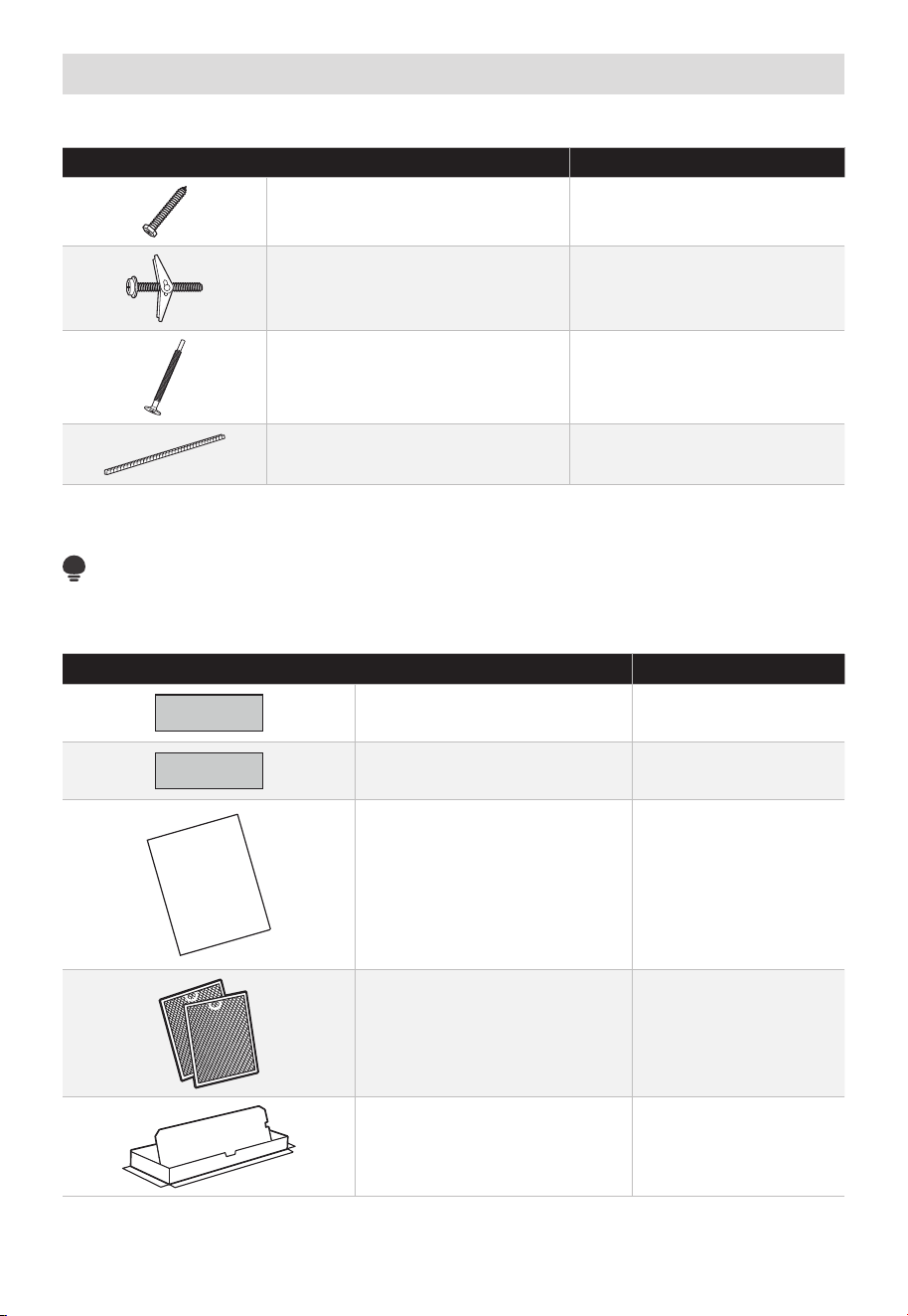
FR-15
Pièces incluses
PAQUET DE MATÉRIEL
PIÈCE QUANTITÉ
Vis à bois (
1
⁄
4
po x 2po) 2
Boulons à genouillère (et écrou
à ailettes) (
3
⁄
16
po x 3po)
2
Vis de machine à alignement
automatique (
1
⁄
4
po-28 x 3
1
⁄
4
po)
3
Oeillet en nylon (pour armoires
métalliques)
1
Vous trouverez le matériel d'installation contenu dans un paquet avec l'appareil. Vérifiez
que vous avez toutes ces pièces.
REMARQUE:
Certaines pièces supplémentaires sont incluses.
PIÈCES SUPPLÉMENTAIRES
PIÈCE QUANTITÉ
Modèle d'armoire supérieure 1
Modèle de mur arrière 1
USER
MANUAL
MANUEL
D’UTILISATION
Manuel d'utilisation 1
Filtres à graisse emballés
séparément
2
Adaptateur d'échappement 1

FR-16
Plateau en verre 1
Écrou de plaque tournante 1
(pour certains modèles)
Grille métallique à convection 1
(pour certains modèles)
Étagère 1
(pour certains modèles)
Filtre pour micro-ondes
PureAir
®
1
Outils dont vous aurez besoin
# 1 Tournevis Phillips Crayon
Règle ou ruban à mesurer
et bord droit
Équerre de
menuisier (en
option)
Blocs de remplissage
ou morceaux de bois de
rebut, si nécessaire pour
l'espacement de l'armoire
supérieure (utilisés
uniquement sur les
installations d'armoires
inférieures encastrées)
Perceuse électrique avec
forets
3
⁄
16
po,
1
⁄
2
po et
5
⁄
8
po
Ciseaux
(pour couper le
modèle, sinécessaire)
Cisailles à toile (pour
amortisseur de coupe,
si nécessaire)
Gants
Scie (sabre, trou ou trou de
serrure)
Répéreur de poteau ou
marteau (en option)
Conduit et ruban de
masquage
Niveau
Lunettes de
sécurité

FR-17
Espace de montage
ESPACE DE MONTAGE
Le bord inférieur de
l'armoire doit être à
30po (76,2 cm) ou
plus de la surface
de cuisson
66po (167,6 cm)
ou plus du sol
au sommet du
micro-ondes
30po
(76,2cm)
min.
13po maximum
(33 cm)
30po (76,2 cm)
16
1
⁄
2
po
(41,9cm)
2po (5,1 cm)
Dosseret
• Si la profondeur de l'armoire,
y compris les portes de
l'armoire, est supérieure à
13po, l'unité doit être espacée
du mur en utilisant des
matériaux adéquats prenant
en charge 150 lb pour
permettre un échappement/
admission appropriée de l'air
par le haut.
REMARQUE:
REMARQUE:
• L'espace entre les armoires doit être de 30po (76,2 cm) de large et exempt d'obstructions.
• Si le four à micro-ondes doit être ventilé à l'extérieur, voir la section relative à
l'échappement de la hotte pour la préparation du conduit d'échappement.
• Lors de l'installation du four à micro-ondes sous des armoires lisses et plates, veillez à
suivre les consignes sur le modèle d'armoire supérieur pour le dégagement du cordon
d'alimentation.
• Pour diriger l'installation, consultez la page 25 pour obtenir des informations sur le
modèle de montage.
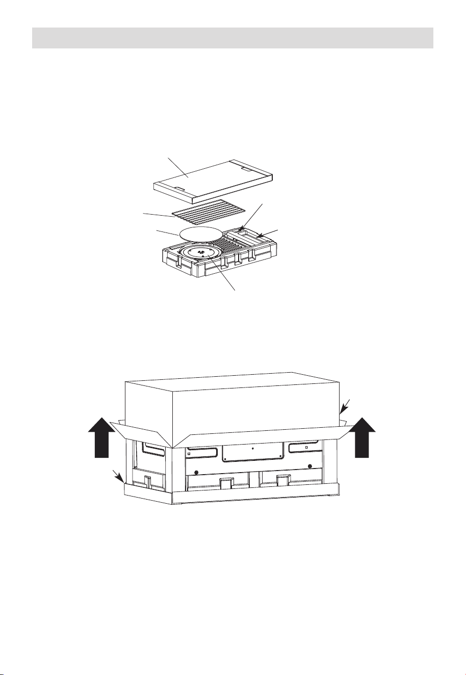
FR-18
1. Installation de la plaque de montage
A. RETRAIT DU FOUR À MICRO-ONDES DU CARTON/RETRAIT DE LA
PLAQUE DE MONTAGE
1. Retirez le panneau de couverture supérieur, les consignes d'installation, l'utilisation
et l'entretien, l'adaptateur d'échappement, l'écrou du plateau tournant, l'étagère, les
filtres, le plateau en verre et le petit sac de matériel. Ne retirez pas le polystyrène qui
protège l'avant du four.
Panneau de couverture supérieur
Étagère (pour
certains modèles)
Tampon EPE
Filtres et anneau de plaque tournante
sous le plateau en verre
Adaptateur d'échappement
Petit sac de matériel
2. Repliez complètement les 4 rabats du carton contre les côtés du carton. Ensuite,
roulez soigneusement le four et le carton sur la face supérieure. Le four doit reposer
dans le polystyrène.
Polystyrène
Carton
3. Tirez le carton vers le haut et éteignez le four.
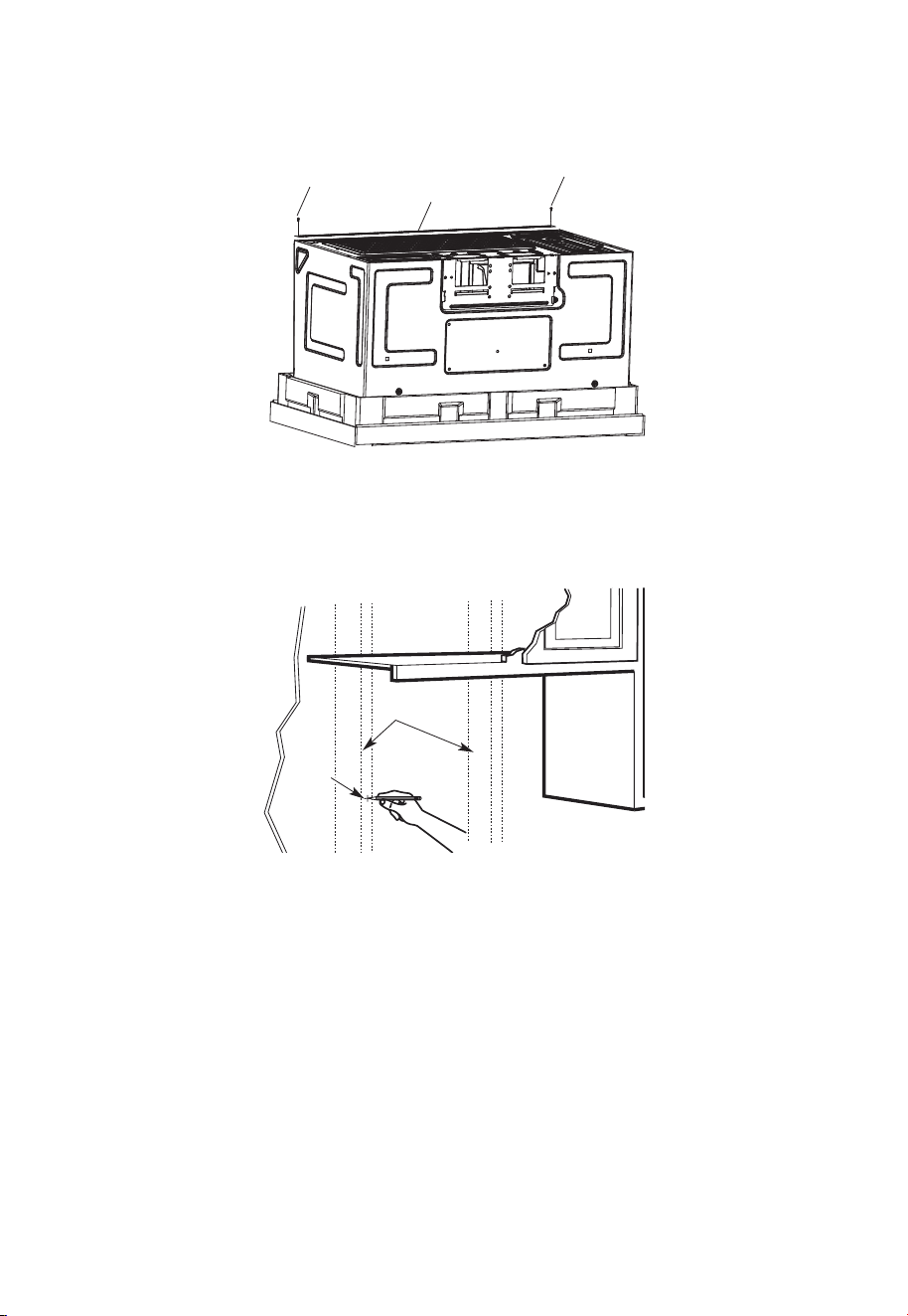
FR-19
4. Coupez le milieu du sac en plastique de protection externe pour retirer la plaque de
montage
Vis
Vis
Plaque de montage
5. Retirez les vis de chaque extrémité de la plaque de montage. Cette plaque sera utilisée
comme modèle de paroi arrière et pour le montage. Réinstallez les vis dans les trous
où elles ont été retirées.
B. REPÉRAGE LES POTEAUX MURAUX
Poteaux
muraux
Centre
1. Répérez les poteaux muraux en utilisant l’une des méthodes suivantes:
-
Répéreur de poteaux muraux – un matériel magnétique qui localise les clous.
-
Utilisez un marteau pour taper légèrement sur la surface de montage pour trouver
un son solide. Cela indiquera un emplacement de poteau.
2. Après avoir localisé le (s) poteau(s), trouvez le centre en sondant le mur avec un petit
clou pour trouver les bords du poteau. Placez ensuite une marque à mi-chemin entre
les bords. Le centre de tous les poteaux adjacents doit être à 16po (40,6 cm) ou 24po
(61 cm) de cette marque.
3. Tracez une ligne au centre des poteau.
LE MICRO-ONDES DOIT ÊTRE CONNECTÉ À AU MOINS UN POTEAU MURAL.
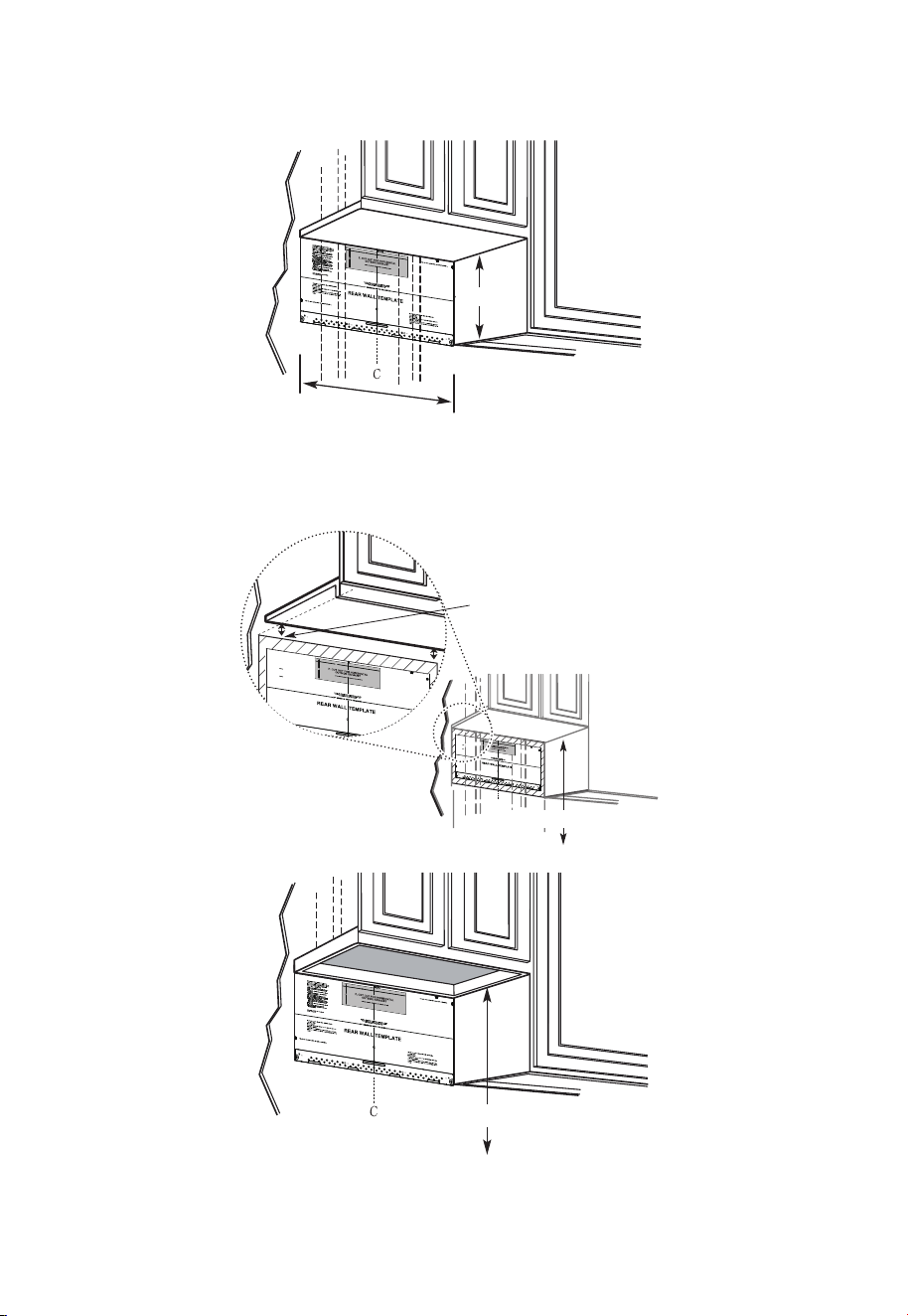
FR-20
C. DÉTERMINATION DE L'EMPLACEMENT DE LA PLAQUE MURALE SOUS
VOTRE ARMOIRE
Position de la plaque - sous l'armoire à fond plat
Au moins 30po
16-1/2po
Tracez une ligne verticale sur le mur au centre de l'espace de 30po de large.
Collez le modèle de mur arrière sur le mur correspondant à la ligne centrale et en
touchant le bas de l'armoire.
Position de la plaque - sous l'armoire inférieure encastrée avec un débordement à l'avant
C
3/
8"
TO
EDGE
N
OT
E:
IT IS VERY IMP
O
RTA
NT
T
O
RE
AD
AND
FO
LL
O
W THE
D
IRE
C
T
I
ON
S
IN
T
H
E
IN
S
T
A
LL
ATI
ON
IN
ST
RUC
TIONS
B
E
F
ORE PR
OCEEDING WIT
H T
HIS
RE
AR W
A
LL
TEMPLATE.
This Re
a
r W
a
ll
Te
mplate
serv
e
s
t
o po
s
itio
n
t
he
bo
tt
om
m
o
u
nting p
la
t
e
a
nd
t
o
lo
ca
t
e
th
e
ho
ri
zo
nt
al
e
xh
au
st
ou
tle
t
.
1.
Use
a
le
ve
l
t
o
ch
eck
th
a
t
t
h
e
t
e
mp
la
te
is
posit
ione
d
a
c
c
u
ra
tely.
2
. Loc
ate
an
d
m
ar
k
at
lea
st
one stud
o
n t
he
le
ft or
ri
ght
sid
e
of the ce
n
te
r
lin
e
.
It
is
import
a
n
t
to use at
l
e
ast one wo
o
d
s
c
rew
mou
n
ted
f
ir
m
ly
in
a
stud
to
s
u
ppor
t the
weig
ht
of t
he
m
ic
r
owave.
M
ark
tw
o additiona
l,
eve
nly
spac
ed
lo
c
atio
ns for
the su
pplied
toggle
bolt
s
.
3.
Dril
l
holes
in
t
he
m
a
rk
e
d
locations.
Where
th
e
re
is
a
stud, drill
a
3
/
16" h
ole
fo
r
woo
d
s
c
rew
s
. F
or
h
o
le
s
th
at d
o
not li
n
e up
w
it
h
a
s
tud,
drill 5/
8
"
holes fo
r
toggle bolts.
DO
NOT INSTALL
T
H
E
MOUN
TIN
G
P
LA
T
E
AT
TH
IS
T
I
M
E
.
4
. R
e
mo
v
e
t
h
e templa
te
from t
he
r
e
ar
wall.
5
.
R
e
v
i
ew th
e
Inst
a
llatio
n
In
st
r
uction
boo
k
fo
r
y
ou
r
in
stalla
tio
n
si
t
uat
io
n
.
L
o
c
ate an
d
mark
ho
l
es
to
align w
ith h
o
les
i
n the
mo
u
n
t
in
g
p
l
ate.
I
MP
ORTANT
:
LO
CATE
AT LEAST ONE
S
TU
D ON EIT
H
ER
S
IDE OF
T
HE CE
NTER
LIN
E.
MA
RK
TH
E
LOCAT
I
ON
FO
R
2
A
DD
ITIONA
L, E
V
E
N
LY
S
P
AC
E
D TOGG
LE B
OL
T
S IN
THE MO
U
N
TIN
G
P
LAT
E
ARE
A.
Lo
cate a
n
d
ma
rk ho
les to
align with holes in
the
mo
unting p
l
a
te.
I
MPO
RTA
N
T:
LOCATE AT
L
E
AST
ONE ST
U
D ON
EI
TH
E
R SID
E
O
F
T
H
E CENTE
RLINE
.
MARK
THE LOCATION
FOR
2 AD
D
I
TI
ON
AL
,
E
V
E
NL
Y
SPACED
TO
GGLE B
OL
T
S IN
THE MO
U
NT
IN
G
PLATE
AR
E
A.
T
r
im
th
e
rea
r
wal
l
temp
late along th
e dotte
d line
.
Trim th
e rear
wa
l
l te
mpl
a
te
a
lo
n
g
th
e
dotted line
.
12"
4"
Da
r
le
vuelta
a
la
h
o
ja
p
a
ra
consu
l
ta
r la
v
ersió
n
en Espa
ño
l.
3/8
"
TO EDGE
N
O
TE
:
I
T
IS
VER
Y
IMPOR
T
AN
T T
O
R
EAD
AN
D
FO
L
LO
W
TH
E D
IR
EC
TI
O
N
S
I
N
T
H
E
I
N
ST
ALL
AT
IO
N
IN
ST
R
U
C
TI
O
N
S
B
EFO
R
E
PR
O
C
EED
IN
G
W
ITH
T
H
I
S
R
EAR
W
AL
L
T
EMPL
AT
E.
Th
is
R
e
a
r
W
a
ll
Te
mp
la
t
e s
er
v
e
s
to
p
o
s
it
i
o
n
th
e
b
o
t
to
m
mo
u
ntin
g
p
la
t
e
a
n
d
t
o l
o
c
at
e
th
e h
o
r
iz
on
ta
l e
x
h
a
us
t
ou
tle
t.
1
.
U
s
e
a
l
ev
e
l to
c
he
c
k
th
a
t
th
e
te
mp
la
t
e is
p
o
sitio
n
e
d
a
c
c
u
r
a
t
e
ly
.
2
.
L
o
c
a
te
a
n
d
ma
r
k
a
t le
a
s
t
o
n
e
s
t
u
d
o
n
t
he
le
ft
o
r
r
ig
ht
s
id
e
o
f
th
e c
e
n
te
r
l
in
e.
It
is
i
mp
o
r
ta
n
t t
o
u
s
e a
t le
a
s
t
o
n
e
w
o
o
d
s
c
r
e
w
mo
u
n
t
ed
f
ir
mly
in
a
s
tu
d
to
s
u
pp
o
r
t t
h
e
w
e
ig
h
t
o
f
th
e
mic
r
o
w
a
v
e
.
Ma
r
k
t
w
o
a
d
d
itio
na
l,
e
v
e
nl
y
s
p
a
ce
d
lo
c
a
tio
n
s
f
o
r
th
e
s
upp
li
e
d t
og
g
le
b
o
lts
.
3.
D
r
il
l h
ole
s
in
t
h
e
ma
r
k
e
d
lo
c
a
tio
n
s
.
W
h
e
r
e th
e
r
e
is
a
s
tu
d
, d
r
i
ll
a
3
/1
6"
h
o
le
fo
r
w
o
od
s
c
r
e
w
s
.
Fo
r
h
o
le
s
th
a
t d
o n
o
t lin
e
u
p
w
ith
a s
t
u
d
,
d
r
ill 5
/
8
" h
o
le
s fo
r
to
g
g
le
b
o
lts
.
D
O
N
O
T
IN
STA
L
L
TH
E
MO
U
N
TIN
G
P
L
ATE
AT TH
IS TIME
.
4
.
R
e
m
o
v
e
th
e
te
mp
la
te
fr
om
t
h
e
r
e
a
r
w
a
ll.
5
.
R
e
v
ie
w
t
he
In
s
ta
ll
atio
n
In
s
tru
c
t
io
n
bo
o
k fo
r
y
ou
r
in
sta
lla
tio
n
s
itu
a
tio
n.
Lo
cate an
d
ma
rk
h
ol
es t
o al
i
g
n w
ith
h
ol
e
s
i
n t
h
e
mo
unti
n
g
pl
a
t
e
.
I
M
PO
R
T
AN
T
:
LOC
A
TE AT
LEAST
ONE ST
U
D
ON
EI
TH
ER
SI
D
E
OF
TH
E C
EN
TER
LIN
E.
MAR
K
T
H
E
LOC
ATIO
N
FO
R
2
AD
D
I
T
I
ON
AL
,
EVEN
L
Y
SPAC
ED
T
OG
GLE
BO
L
T
S
I
N
TH
E
MOUN
T
I
N
G
PLATE
AR
EA
.
Lo
cate
an
d
ma
rk
h
ol
es t
o al
i
g
n w
i
t
h
h
ol
e
s
in t
h
e
mo
un
tin
g pl
a
t
e
.
IMPO
R
T
AN
T:
LOC
AT
E AT
LEAS
T
ON
E ST
U
D
ON
EI
T
H
ER
SID
E
O
F
TH
E
C
EN
TE
R
LIN
E
.
MAR
K
T
H
E
LO
C
ATIO
N
F
O
R
2
AD
D
I
TI
ON
AL
, EVEN
L
Y
SPA
C
E
D
T
O
G
GLE
BO
L
T
S
I
N
TH
E
MO
U
N
TI
N
G
P
LAT
AR
EA.
Trim
th
e
r
e
ar
wall
t
em
p
lat
e
a
l
ong
th
e
d
otted
l
i
ne.
Trim
th
e
r
ear
wal
l
tem
pl
ate
a
l
ong
th
e
dotted
li
ne.
12
"
4"
D
arle
v
u
el
t
a
a
la
h
o
ja
p
a
r
a
c
o
n
s
u
lt
a
r
la
v
e
r
si
ó
n
e
n
E
s
p
añ
o
l.
Tracez une ligne sur
le mur arrière égale
à la profondeur du
débordement avant.
30po vers la plaque de cuisson
Position de la plaque - sous le fond de l'armoire encastrée et encadrée
30po vers la plaque de cuisson
Tracez une ligne verticale sur le mur au centre de l'espace de 30po.
Collez le modèle de mur arrière sur le mur correspondant à la ligne centrale et en
touchant le cadre inférieur de l'armoire.
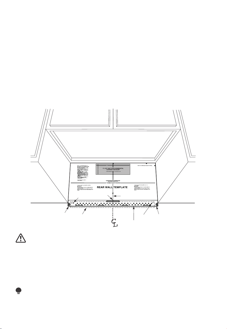
FR-21
Vos armoires peuvent avoir des garnitures décoratives qui interfèrent avec l'installation
du micro-ondes.
Retirez la garniture décorative pour installer correctement le micro-ondes et le mettre à
niveau.
LE MICRO-ONDES DOIT ÊTRE DE NIVEAU.
Utilisez un niveau d'eau pour vous assurer que le fond de l'armoire est de niveau.
Si les armoires ont un débordement avant uniquement, sans cadre arrière ou latéral,
installez la plaque de montage à la même distance que la profondeur du débordement
avant. Cela maintiendra le niveau du micro-ondes.
1. Mesurez la profondeur intérieure du débordement avant.
2. Tracez une ligne horizontale sur le mur arrière à une distance égale sous le fond de
l'armoire que la profondeur intérieure du débordement avant.
3. Pour ce type d'installation avec débordement avant uniquement, alignez les pattes de
montage sur cette ligne horizontale, sans toucher le fond de l'armoire comme décrit à
l'étape D.
D. ALIGNEMENT DE LA PLAQUE MURALE
3/8" TO EDGE
Ligne horizontale
Zone E
Tracez une ligne horizontale sur le mur
au bas du «modèle de mur arrière».
Ligne horizontaleTrou A
Trou B
Encoches
de l'axe
central
Dessinez une ligne verticale
sur le mur à partir du centre
de l'armoire supérieure
MISE EN GARDE :
Portez des gants pour éviter de couper les doigts sur les bords tranchants.
1. Tracez une ligne verticale sur le mur au centre de l'espace de 30po de large.
2. Tracez une ligne horizontale sur le mur au bas du «modèle de mur arrière».
3. Trouvez un poteau mural dans la zone «E» de la plaque de montage. Reportez-vous à
la section 1B. Repérage des poteaux muraux.
4. Pour fixer la plaque de montage dans le poteau, percez un trou de 3/16po dans le
poteau en bois. Percez un trou de 5/8po pour le boulon à genouillère à un autre
endroit (trou A ou trou B)
REMARQUE:
NE MONTEZ PAS LA PLAQUE POUR LE MOMENT.
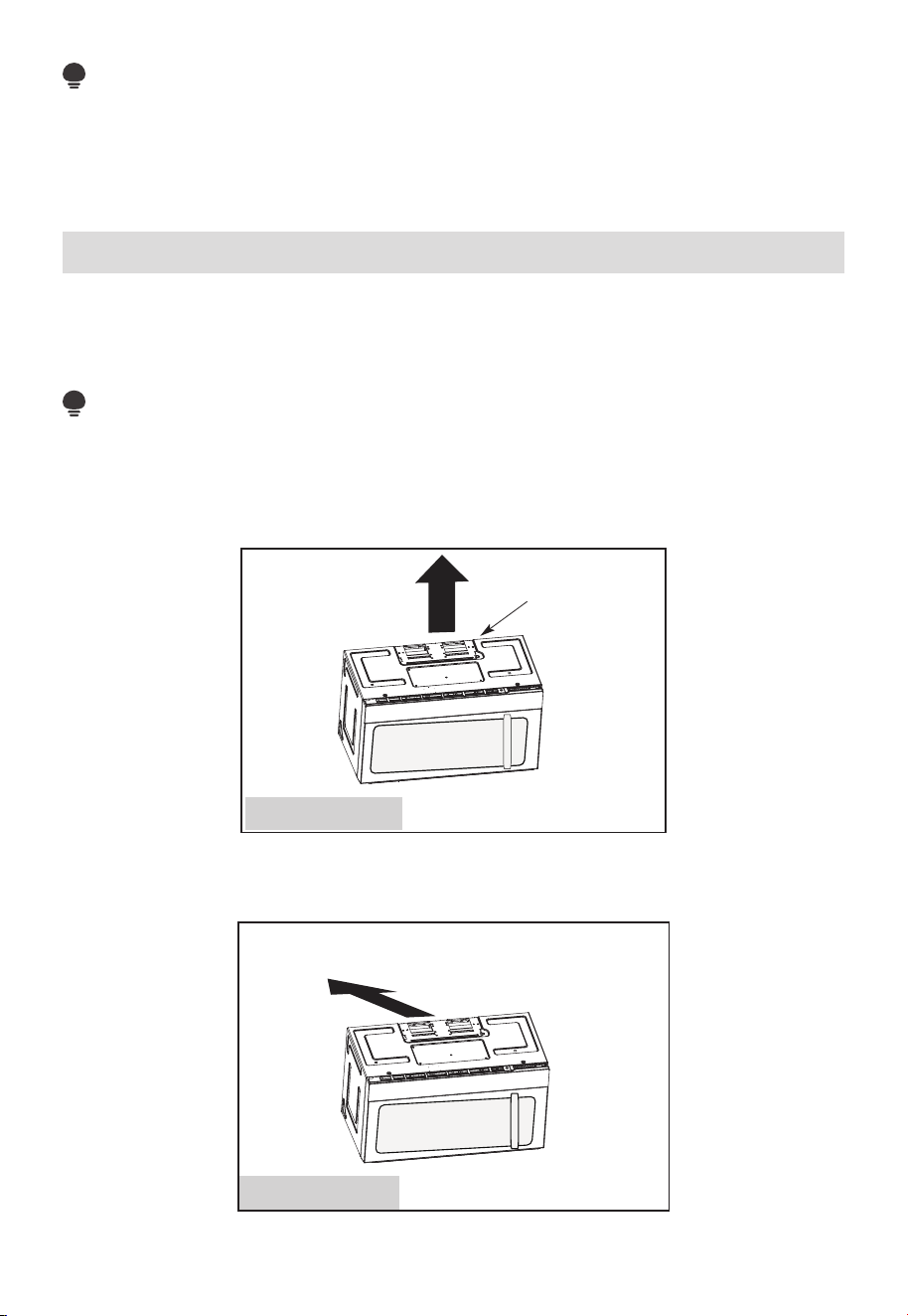
FR-22
REMARQUE:
Les trous A et B sont à l'intérieur de la zone E. Si aucun des trous A et B n'est dans un
poteau, trouvez un autre quelque part dans la zone E et tracez un cercle pour l'aligner
avec le poteau. Il est important d'avoir au moins une vis à bois montée fermement dans
un poteau pour supporter le poids du micro-ondes. Mettez la plaque de montage de
côté.
2. Types d'installation (choisissez A, B ou C)
Ce four à micro-ondes est conçu pour s'adapter aux trois types de ventilation suivants:
A. Échappement supérieur extérieur (conduit vertical)
B. Échappement arrière extérieur (conduit horizontal)
C. Recirculation (sans conduit de ventilation)
REMARQUE:
Ce micro-ondes est expédié assemblé pour la recirculation. Sélectionnez le type de
ventilation requis pour votre installation et passez à cette section.
A. ÉCHAPPEMENT SUPÉRIEUR EXTÉRIEUR (CONDUIT VERTICAL)
Adaptateur en place pour
l'échappement supérieur
extérieur
Voir page 26
B. ÉCHAPPEMENT ARRIÈRE EXTÉRIEUR (CONDUIT HORIZONTAL)
Voir page 33
L'adaptateur doit être
déplacé vers l'arrière pour
l'échappement arrière extérieur
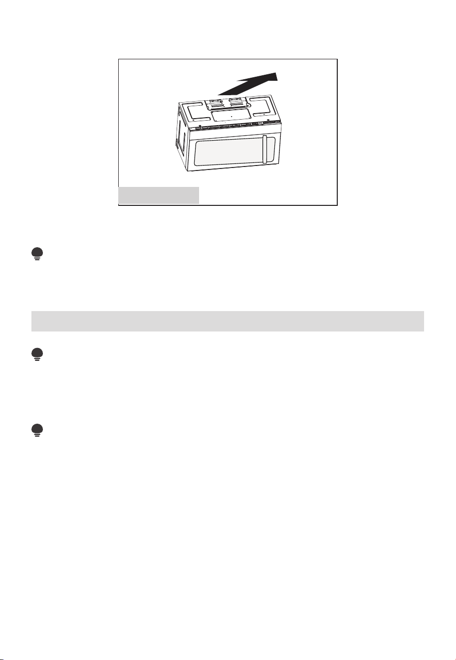
FR-23
C. RECIRCULATION (SANS CONDUIT DE VENTILATION)
Voir page 41
Les modèles sont expédiés avec un système de ventilation à recirculation. Certains modèles
disposent d'un filtre à charbon jetable installé pour aider à éliminer la fumée et les odeurs.
REMARQUE:
Lisez les deux pages suivantes uniquement si vous prévoyez d'évacuer vos gaz
d'échappement vers l'extérieur. Si vous prévoyez de faire recirculer l'air dans la pièce,
passez à la page 23-26.
Consignes d'installation pour les conduits d'échappement externes
REMARQUE:
Si vous devez installer des conduits, notez que la longueur totale du conduit de 3
1
⁄
4
po
x 10po (8,2 x 25,4 cm) rectangulaire ou 5po (12,7 cm) de diamètre/6po (15,2 cm) de
diamètre de conduit rond ne doit pas dépasser 120 pieds équivalents (36,5 m).
La ventilation extérieure nécessite un CONDUIT D'ÉCHAPPEMENT EXTERNE. Lisez
attentivement ce qui suit.
REMARQUE:
Il est important que la ventilation soit installée en utilisant la voie la plus directe et avec le
moins de coudes possible. Cela garantit une ventilation claire des gaz d'échappement et
aide à prévenir les blocages.
Assurez-vous également que les amortisseurs oscillent librement et que rien ne bloque
les conduits.
Raccord d'échappement:
L'adaptateur d'échappement a été conçu pour s'accoupler avec un conduit rectangulaire
standard de 3
1
⁄
4
po x 10po (8,2 x 25,4 cm).
Si un conduit rond est nécessaire, un adaptateur de transition rectangulaire à rond doit
être utilisé. Un conduit de diamètre A5po (12,7 cm)/6po (15,2 cm) est utilisable.
Longueur maximale du conduit:
Pour un mouvement d'air satisfaisant, la longueur totale du conduit rectangulaire est de
3
1
⁄
4
po x 10po (8,2 x 25,4 cm)
ou d'un conduit rond de 5po (12,7 cm) de diamètre/6 po (15,2 cm) de diamètre ne doit pas
dépasser l'équivalent de 120 pieds (36,5 m).
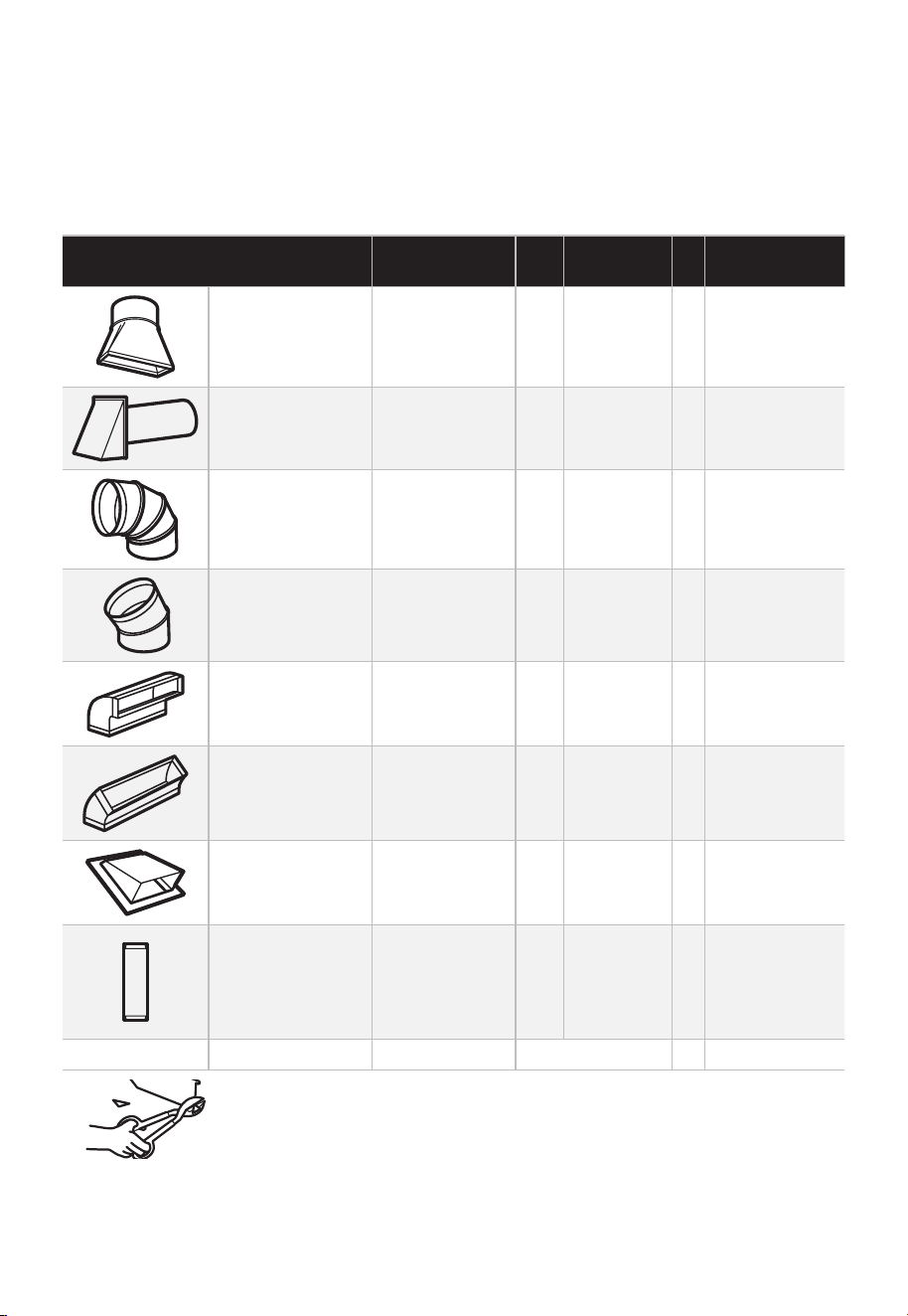
FR-24
Les coudes, les transitions, les capuchons de mur et de toit, etc., présentent une
résistance supplémentaire au flux d'air et sont équivalents à une section de conduit droit
qui est plus longue que leur taille physique réelle. Lors du calcul de la longueur totale du
conduit, ajoutez les longueurs équivalentes de toutes les transitions et adaptateurs plus
la longueur de toutes les sections droites du conduit. Le tableau ci-dessous vous montre
comment calculer la longueur équivalente totale des conduits en utilisant les pieds
approximatifs de longueur équivalente de certains conduits typiques.
PIÈCES DE CONDUIT
LONGUEUR
ÉQUIVALENTE
x
NOMBRE
UTILISÉ
=
LONGUEUR
ÉQUIVALENTE
Adaptateur
de transition
rectangulaire à
rond*
5 pieds.
(1,5 m)
x ( ) = Pieds. ou m
Capuchon mural
40 pieds.
(12,2m)
x ( ) = Pieds. ou m
Coude à 90°
10 pieds.
(3 m)
x ( ) = Pieds. ou m
Coude à 45°
5 pieds.
(1,5 m)
x ( ) = Pieds. ou m
Coude à 90°
25 pieds.
(7,6m)
x ( ) = Pieds. ou m
Coude à 45°
5 pieds.
(1,5 m)
x ( ) = Pieds. ou m
Capuchon de toit
24 pieds.
(7,3m)
x ( ) = Pieds. ou m
Conduit droit 6po
(15,2 cm) rond
ou 3
1
⁄
4
po x 10po
(8,2 x 25,4 cm
rectangulaire)
1 pied.
(0,3 m)
x ( ) = Pieds. ou m
Total des gaines = Pieds. ou m
* IMPORTANT: Si un adaptateur de transition rectangulaire à rond
est utilisé, les coins inférieurs de l'amortisseur devront être coupés
pour s'adapter, à l'aide des cisailles à toile, afin de permettre le
libre mouvement de l'amortisseur.
Les longueurs équivalentes des pièces de conduit sont basées sur des tests réels et
reflètent les exigences de bonnes performances de ventilation avec n'importe quelle
hotte de ventilation.
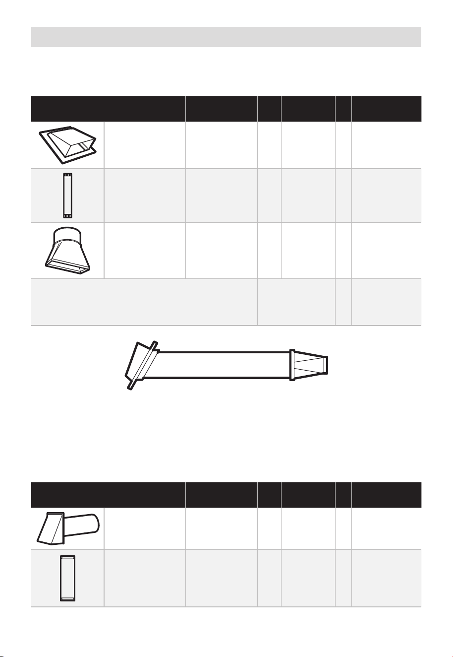
FR-25
Conduites d'échappement externes
ÉCHAPPEMENT SUPÉRIEUR EXTÉRIEUR (EXEMPLE UNIQUEMENT)
Le tableau suivant décrit un exemple d'installation de gaines possible.
PIÈCES DE CONDUIT
LONGUEUR
ÉQUIVALENTE
x
NOMBRE
UTILISÉ
=
LONGUEUR
ÉQUIVALENTE
Capuchon de toit
24 pieds.
(7,3m)
x (1) =
24 pieds.
(7,3m)
12 pieds. (3,6 m)
Conduit droit
(rond 6po/
15,2 cm)
12 pieds.
(3,6m)
x (1) =
12 pieds.
(3,6m)
Adaptateur
de transition
rectangulaire à
rond*
5 pieds.
(1,5 m)
x (1) =
5 pieds.
(1,5 m)
Les longueurs équivalentes des pièces de conduit
sont basées sur des tests réels et reflètent les
exigences de bonnes performances de ventilation
avec n'importe quelle hotte de ventilation.
Longueur totale =
41 pieds.
(12,5m)
* IMPORTANT: Si un adaptateur de transition rectangulaire à rond est utilisé, les coins
inférieurs de l'amortisseur devront être coupés pour s'adapter, à l'aide des cisailles à toile,
afin de permettre le libre mouvement de l'amortisseur.
ÉCHAPPEMENT ARRIÈRE EXTÉRIEUR (EXEMPLE UNIQUEMENT)
Le tableau suivant décrit un exemple d'installation de gaines possible.
PIÈCES DE CONDUIT
LONGUEUR
ÉQUIVALENTE
x
NOMBRE
UTILISÉ
=
LONGUEUR
ÉQUIVALENTE
Capuchon mural
40 pieds.
(12,2m)
x (1) =
40 pieds.
(12,2m)
3 pieds.
Conduit droit
(3
1
⁄
4
pox 10po/
8,2 x 25,4cm
rectangulaire)
3 pieds.
(0,9 m)
x (1) =
3 pieds.
(0,9m)

FR-26
Coude à 90°
10 pieds.
(3 m)
x (2) =
20 pieds.
(3 m)
Les longueurs équivalentes des pièces de conduit
sont basées sur des tests réels et reflètent les
exigences de bonnes performances de ventilation
avec n'importe quelle hotte de ventilation.
Longueur totale =
63 pieds.
(19,2 m)
REMARQUE:
Pour l'échappement arrière, il faut prendre soin d'aligner l'échappement avec l'espace
entre les poteaux, ou le mur doit être préparé au moment de sa construction en laissant
suffisamment d'espace entre ceux-ci pour accueillir l'échappement.
A. ÉCHAPPEMENT SUPÉRIEUR EXTÉRIEUR (conduit vertical)
APERÇU DE L'INSTALLATION
A1. Fixez la plaque de montage au mur
A2. Préparez l'armoire supérieure
A3. Configurez le souffleur du micro-ondes pour l'échappement supérieur/extérieur
A4. Vérifiez le fonctionnement de l'amortisseur
A5. Montez le four à micro-ondes
A6. Régler l'adaptateur d'échappement
A7. Connectez les gaines
12"
4"
NOTE:
READ AND F
O
I
T
I
S
V
ERY
LLO
I
W
MPO
T
HE
R
D
TANT T
O
IRECTIO
IN THE INSTALLATI
ON
INSTRU
CTIO
N
N
S
S
BE
F
O
RE
PRO
H
T
H
TI W G N I D E E
C
IS
REAR
W
ALL
TEM
PL
A
TE
.
ll Templ
a
te s
erv
es t
o
p
1
ou
a
. Us
mo
u
tl
e
t.
ntin
e
a l
T
hi
s
Rea
g
p
rW
l
a
a
t
e
a
nd
to
lo
ca
te
th
e
h
ori
z
o
s
o
n
itio
ta
n
l e
t
h
xh
e b
au
o
st
t
t
o
m
ionedto check
tha
t
th
e
t
e
mplate
s
o
p si
it
pl
ar
k hol
es
to a
li
gn with holes
in the
L
oca
t
mounting
RTANT
e and m
:
ate
.
IMPO
E
AT LEA
THE CENT
HE LO
CATIO
L
OC
AT
E
RL
INE
ST
.
O
NE STUD ON EI F O
E D I SRE H
T
SP
AC
E
AREA.
MAR
K
T
D TO
GGLE
BO
NF
LT
S
O
IN
R 2 ADD
IT
THE MO
IO
UN
NA
TING
L, EVENL
PLA
TE
Y
Trim the r
e
ar wal
l template a
long
the
dott
ed
l
ine.
k
h
ole
s to
a
l
i g
n with h
ole
s
in t
he
m
ounting
L
oca
te a
n
d
mar
O
RT
AN
T
plate.
:IMP
AT LEA
THE
CENT
HE
L
OCATIO
SP
LOCATE
ER
L
I
NE.
I E N
O
D
U T
S E
N O
TS THER SI
D
E OF
AR
EA.
MARK
ACED
T
T
OG
G
LE B
O
N
FO
LTS IN
R 2
ADDITION
THE
MO
UN
A
T
ING
L,
EV
ENL
PLATE
Y
Trim the rear
w
a
l
l te
m
plate along
t
he do
tt
ed
lin
e.
3/8"
TOEDGE
2. L
o
c
c
cu
a
te
r
a
e
a
tely
v
nd
el
.
m
a
r
k a
t leas
t
o
d
u
ts
e
n
o
n
th r
o
t
f
e
l
e
igh
t
si
d
e of
t
he cente
rl
eni
.
r
It is im
p
o
rta
nt to
u
s
e
at l
e
ts
a one
wood
sc
rew
mo
ro
unte
d
wa
v
fi
e.
r
M
ml
y
ar
i
k
n
t
a
w
s
o
a
tud
d
di
t
i
to
s
up
p
ona
l,
ev
or
en
t
the
w
ly
s
e
pa
ight
ced
e mic
f
e
o
r
s
i
n
t
he
th
s
e
u
m
ppl
ar
k
ied to
ed
l
o
g
c
g
le bo
l
ation
t
s
s
.
.
Wh
ere t
her
e is
lo
o
f
a
c
th
3. Dr
a
th
s
i
tio
at
ll
tu
n
h
d
s
ol
d
ri
l
l a
3/1
6"
h
ole for
w
oo
d
sc
r
e
w
s
.
F
o
r
h
o
l
es
do
,
h t i
w
p
u
e
a
stud, dri
l
l
5/8
" h
oles
fo
r
e bo
n
o
lts
t
li
n
.
NO
T
t
oggl
IN
STAL
L
T
HE
MO
U
N
TI
NG
P
L
ATE
AT
4.
R
e
T
m
HI
S
T
D
O
th
IME.
e te
o
v
e
mp
l
a
te fr
omth
e r
ea
r
wall
.
5.Re
v
ie
w
the I
n
stall
a
t s n I n
o i
t ruc
t
i
on bo
o
k for you
r
instal
l
a
t
io
n s
it
ua
tio
n
.
Dar
le
vu
el
t
a
ala
hojapa
raco
ns
ul
t
ar
la
v
e
r
si
ón
en
Espa
ño
l.
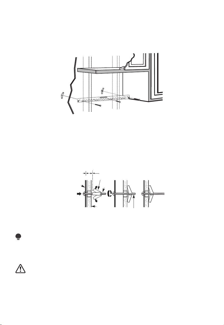
FR-27
REMARQUES IMPORTANTES :
1. Assurez-vous que les vis du moteur du souffleur et de la plaque du souffleur sont bien
serrées lors de leur installation. Cela aidera à éviter les vibrations excessives.
2. Assurez-vous que le câblage du moteur a été correctement acheminé et sécurisé, et
que les câbles ne sont pas pincés.
A1. FIXEZ LA PLAQUE DE MONTAGE AU MUR
• Fixez la plaque au mur à l'aide de boulons à genouillère.
• Au moins une vis à bois doit être utilisée pour fixer la plaque à un poteau mural.
1. Retirez les ailettes à genouillère des boulons
2. Insérez les boulons dans la plaque de montage à travers les trous destinés à entrer
dans la cloison sèche et fixez à nouveau les ailettes à genouillère à 3/4po (19 mm) sur
chaque boulon.
Pour utiliser les boulons à genouillère:
Espacement pour les
bascules de plus de
l'épaisseur du mur
Ailettes à genouillère
Boulon à
genouillère
Extrémité du boulon
Mur
Plaque de
montage
3. Placez la plaque de montage contre le mur et insérez les ailettes à genouillère dans les
trous du mur pour monter la plaque.
REMARQUE:
Avant de serrer les boulons à genouillère et la vis à bois, assurez-vous que le bas de la
plaque de montage touche le bas de l'armoire lorsqu'il est poussé contre le mur et que la
plaque est correctement centrée sous l'armoire.
MISE EN GARDE :
Soyez prudent et évitez de pincer les doigts entre l'arrière de la plaque de montage et le
mur.
4. Serrez tous les boulons. Retirez la plaque du mur pour aider à serrer les boulons.
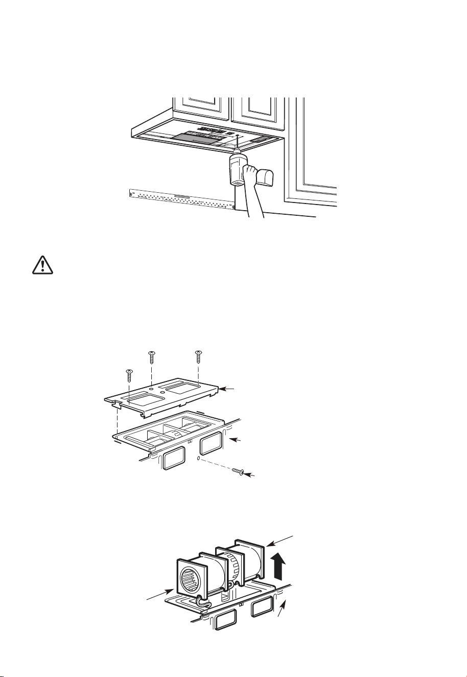
FR-28
A2. UTILISER LE MODÈLE D'ARMOIRE SUPÉRIEURE POUR LA PRÉPARATION
DE L'ARMOIRE SUPÉRIEURE
Vous devez percer des trous pour les vis de support supérieures, un trou suffisamment
grand pour le cordon d'alimentation et une découpe suffisamment grande pour
l'adaptateur d'échappement.
1. Lisez les consignes relatives au MODÈLE D'ARMOIRE SUPÉRIEUR.
2. Collez-le sous l'armoire supérieure.
3. Percez les trous en suivant les consignes relatives au MODÈLE D'ARMOIRE SUPÉRIEUR.
MISE EN GARDE :
Portez des lunettes de sécurité lorsque vous percez des trous dans le fond de l'armoire.
A3. ADAPTATION DUSOUFFLEUR DU MICRO-ONDES POUR L'ÉCHAPPEMENT
SUPÉRIEUR EXTÉRIEUR
1. Placez le micro-ondes en position verticale, avec la partie supérieure de l'appareil
orientée vers le haut.
Plaque de soufflage
Arrière du micro-ondes
Vis du moteur du souffleur
Retirez la vis qui maintient la plaque du souffleur au micro-ondes. Retirez et conservez la
vis, en maintenant le moteur du souffleur au micro-ondes.
2. Retirez délicatement l'unité de soufflage. Les câbles s'étendront suffisamment loin
pour vous permettre de régler l'unité de soufflage.
Extrémité B
Arrière du micro-ondes
Extrémité A

FR-29
3. Faites rouler l'unité de soufflage à 90° de sorte que les ouvertures des pales du
ventilateur soient tournées vers le haut du micro-ondes.
Avant la rotation Après la rotation
Arrière du
micro-ondes
Arrière du
micro-ondes
4. Replacez l'unité de soufflage dans l'ouverture.
APRÈS : Ouvertures des pales de
ventilateur orientées vers le haut
Arrière du
micro-ondes
MISE EN GARDE :
Ne tirez ni n'étirez le câblage de l'unité de soufflage. Assurez-vous que les câbles ne sont
pas pincés et qu'ils sont correctement fixés.
5. Fixez l'unité de soufflage au micro-ondes avec la vis retirée à l'étape 1. Assurez-vous
que la vis est bien serrée.
6. Remplacez la plaque du souffleur avec la vis retirée à l'étape 1. Assurez-vous que la vis
est bien serrée.
Arrière du
micro-ondes
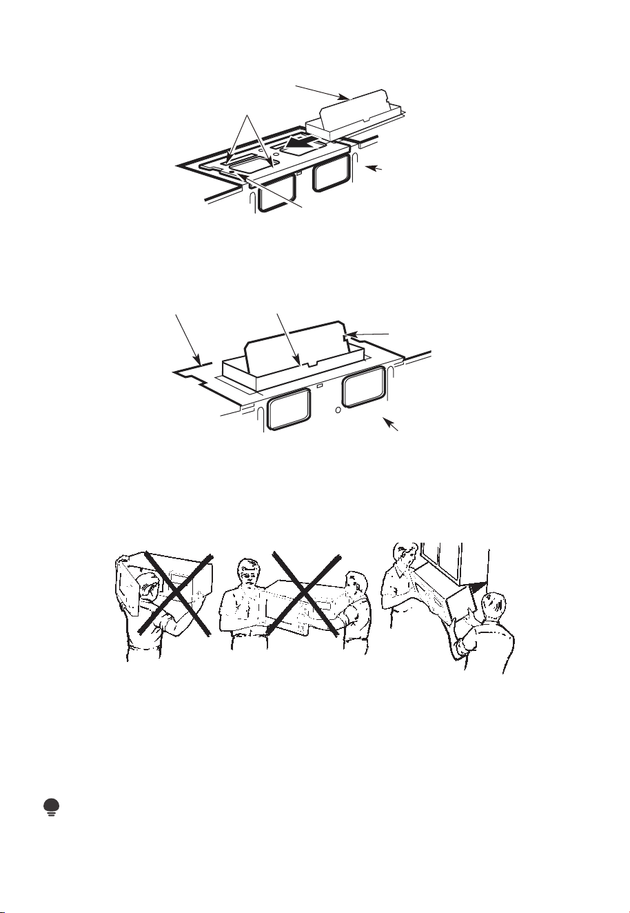
FR-30
7. Fixez l'adaptateur d'échappement au sommet de la plaque du souffleur en le faisant
glisser dans les guides de la plaque du souffleur.
Adaptateur
Guide
Arrière du
micro-ondes
Onglet de verrouillage
Poussez fermement jusqu'à ce qu'il soit dans les languettes de verrouillage. Veillez à ce
que la charnière de l'amortisseur soit installée de manière à ce que l'amortisseur oscille
librement.
A4. VÉRIFIEZ LE BON FONCTIONNEMENT DE L'AMORTISSEUR
Arrière du micro-ondes
Amortisseur
Adaptateur d'échappement
Plaque de soufflage
• Assurez-vous que le ruban adhésif fixant l'amortisseur est retiré et que le celui-ci pivote
facilement avant de monter le micro-ondes.
• Vous devrez effectuer des ajustements pour vous assurer d'un alignement correct avec
le conduit d'échappement de votre maison après l'installation du micro-ondes.
A5. MONTER LE FOUR À MICRO-ONDES
POUR FACILITER L'INSTALLATION ET PROCURER LA SÉCURITÉ PERSONNELLE, NOUS
VOUS RECOMMANDONS QUE DEUX PERSONNES INSTALLENT CE FOUR À MICRO-
ONDES.
IMPORTANT: Ne saisissez pas et n'utilisez pas la poignée ou le bouclier thermique
pendant l'installation. Ne retirez pas les entretoises en carton entre le bouclier thermique
et la porte.
REMARQUE:
Si votre armoire est en métal, utilisez l'œillet en nylon autour du trou du cordon
d'alimentation pour éviter de couper celui-ci.
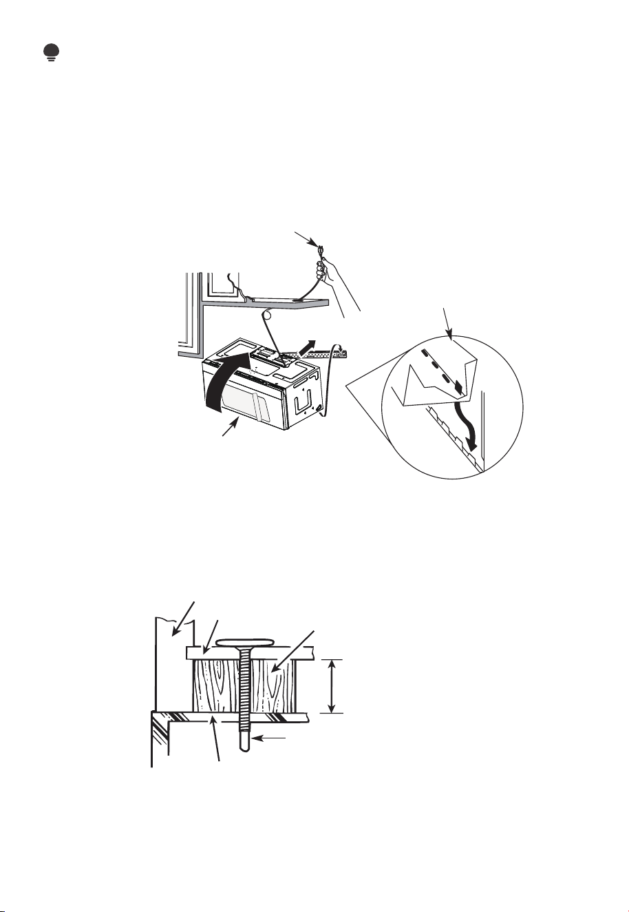
FR-31
REMARQUE:
Nous vous recommandons d'utiliser des blocs de remplissage si l'avant de l'armoire est
suspendu sous de l'étagère inférieure de celle-ci.
IMPORTANT: Si les blocs de remplissage ne sont pas utilisés, le serrage excessif des vis
peut endommager le boîtier.
REMARQUE: Lors du montage
du four à micro-ondes, enfilez le
cordon d'alimentation à travers
le trou situé au bas de l'armoire
supérieure. Gardez-le bien serré
tout au long des étapes 1 à 3. Ne
pincez pas le cordon ou ne soulevez
pas le four en tirant sur le cordon.
1. Soulevez le micro-ondes,
inclinez-le vers l'avant
et accrochez les fentes
du bord inférieur arrière
sur quatre languettes
inférieures de la plaque de
montage.
2 Tournez l'avant du four
contre le fond de l'armoire.
3. Insérez une vis à alignement automatique dans le trou central supérieur de l'armoire.
Fixez temporairement le four en tournant la vis d'au moins deux tours complets après
l'engagement des fils. (Il sera complètement serré plus tard.) Assurez-vous de garder
le cordon d'alimentation serré. Veillez à ne pas pincer le cordon, en particulier lors du
montage affleurant au bas de l'armoire.
Façade de l'armoire
Étagère inférieure de l'armoire
Bloc de remplissage
Équivalent à la profondeur de
l'encastrement de l'armoire
Vis à alignement automatique
Dessus du four à micro-ondes
4. Fixez le four à micro-ondes à l'armoire supérieure.
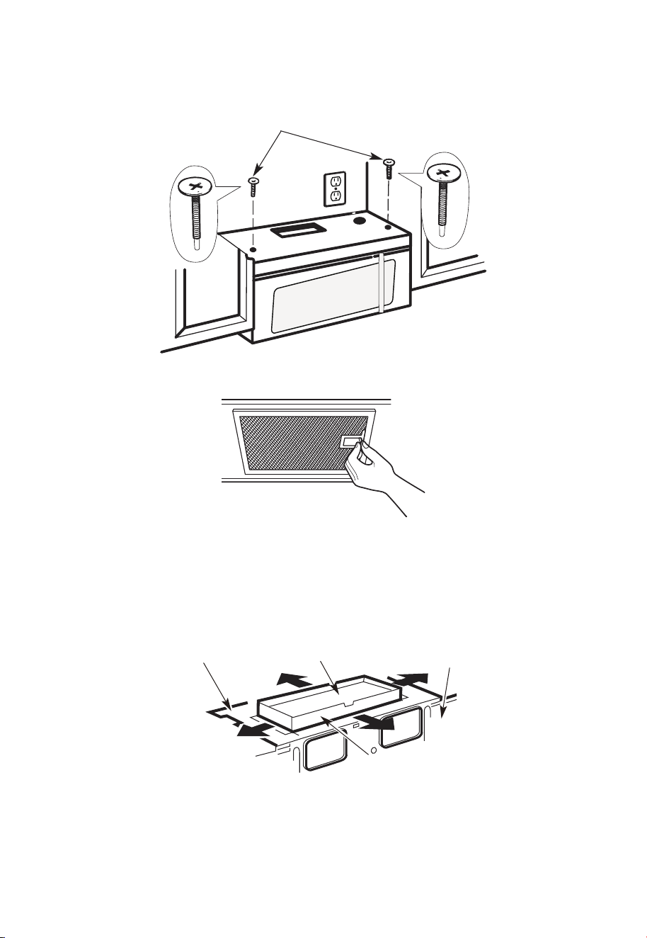
FR-32
5. Insérez 2 vis à alignement
automatique à travers les
trous extérieurs de l'armoire
supérieure. Tournez deux tours
complets sur chaque vis.
6. Serrez les deux vis extérieures au sommet du four à micro-ondes. (Tout en serrant les
vis, maintenez le four à micro-ondes en place contre le mur et l'armoire supérieure.)
7. Installez des filtres à graisse. Voir le guide relatif à l'utilisation et à l'entretien emballé
avec le micro-ondes.
A6. RÉGLER L'ADAPTATEUR D'ÉCHAPPEMENT
Ouvrez l'armoire supérieure et réglez l'adaptateur d'échappement pour le connecter au
conduit de la maison.
Plaque de soufflage
Amortisseur
Arrière du
micro-ondes
Pour le réglage d'avant en
arrière ou d'un côté à l'autre,
faites glisser l'adaptateur
d'échappement au besoin
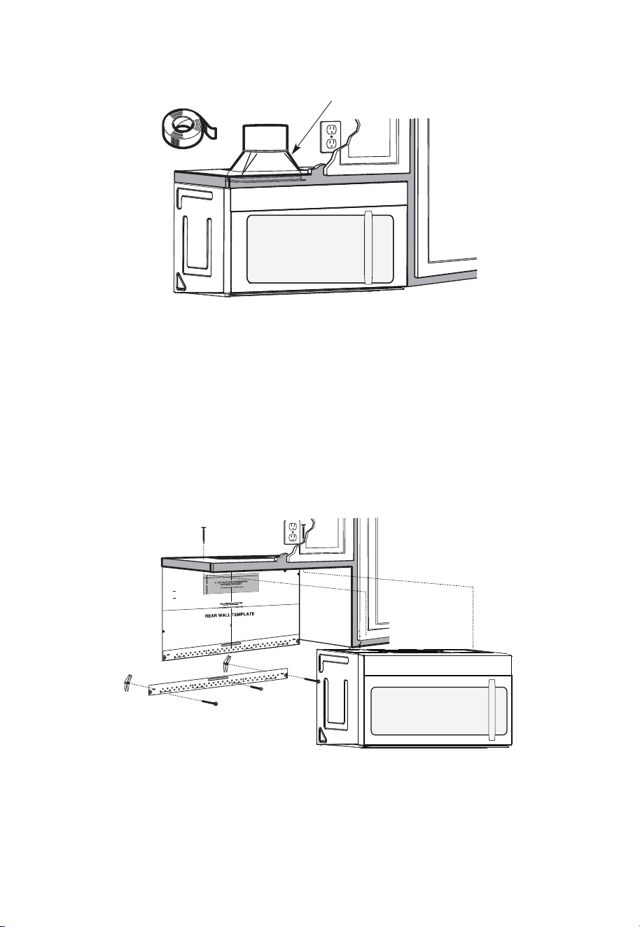
FR-33
A7. RACCORDEMENT DES GAINES
Conduit de la maison
1. Étendez le conduit de la maison vers le bas pour le connecter à l'adaptateur
d'échappement.
2. Scellez les joints du conduit d'échappement à l'aide de ruban adhésif de conduit de
four pour les applications à haute température
B. ÉCHAPPEMENT ARRIÈRE EXTÉRIEUR (conduit horizontal)
APERÇU DE L'INSTALLATION
B1. Préparez le mur arrière
B2. Retirer la plaque du souffleur
B3. Fixez la plaque de montage au mur
B4. Préparez l'armoire supérieure
B5. Réglez le souffleur
B6. Monter le four à micro-ondes
12"
4"
NOTE
:
REA
D AND FO
I
T
I
S
V
ERY
LLO
I
W
MPO
T
HE
R
D
TANT
T
O
IRECTIO
IN THE INSTALLAT
I
ON I
NSTRU
CTI
O
N
N
S
S
B
EF
O
RE PR
O
H
T
H T I
W
G N
I
D E
E
C IS
REAR WA
L
L TEM
PL
ATE
.
ll Te
mpl
a
te
serv
es
to p
1
ou
a
. Us
mou
tle
t.
ntin
e
a l
T
h
is
R
ea
g
p
rW
l
a
a
t
e
and
to
loca
te
th
e h
or
iz
o
s
o
n
itio
t
a
n
l e
t
h
xh
e b
au
o
st
t
t
o
m
ioned
to
chec
k tha
t
th
e
t
e
m
pl
at
e
is
p
osit
pl
ark
holes
to
ali
gn wi
th holes
i
n t
he
L
ocat
mounting
RTANT
e and m
:
ate
.
IMPO
E
AT LEA
THE CENT
HE LOCATIO
L
O
C
AT
ERL
INE
ST
.
ONE STUD
ON EI
F
O
ED I S R
E H
T
SP
AC
E
AREA.
MAR
KT
D T
OGGLE
BO
NF
LT
S
O
I
N
R 2 ADD
IT
THE MO
IO
UN
NA
T
ING
L, EV
EN
L
P
LATE
Y
Trim the
re
ar wal
l tem
plat
e along
the
dott
e
d l
ine.
k
h
ole
s to g
ila n w
ith holes
in t
he
moun
tin
g
Loca
te a
n
d
mar
O
RTAN
T
plate.
:IMP
AT LEA
THE CENT
HE
L
O
CATIO
SP
LOCA
T
E
ERLI
N
E.
I
E
N O
D
U
T S E
N O T
S
T
HE
R S
I
D
E
OF
ARE
A.
MA
RK
ACED
T
T
OGG
LE BO
N
F
O
LTS IN
R 2 ADD
ITION
T
H
E
M
OUN
A
TING
L,
EVENL
PLATE
Y
Trim the rear
w
al
l t
e
m
plat
e
a
longt
he dotted
li
ne.
3/8"
TOEDGE
2. L
o
c
c
c
u
a
te
r
a
e
a
t
e
ly
v
nd
el
.
m
a
r
k a
t leas
t
o
d
u
ts
e
n
o
n
th r
o t
f
e l
e
i
ght
si
de of th
e c
ent
e
r
en
il
.
r
It is importa
nt to
use at
l
eas t o
ne
wo
od
sc
rew
mo
ro
unte
d
wa
v
fi
e.
r
M
ml
y
ar
i
k
n
t
a
w
s
o
a
t
ud
d
diti
to sup
p
ona
l, ev
or
en
t the w
ly
s
e
pa
ight
ced
e mic
f
e
o
r
s
i
n
t
he
t
h
s
e
u
m
p
pl
ark
ied to
ed l
o
g
c
g
le bo
l
ati
on
t
s
s
.
.
Wher
e th
er
e is
lo
o
f
a
c
th
3. Dr
a
th
s
i
tio
at
ll
tu
n
h
d
s
ol
d
ri
l
l
a
3/1
6" hol
e fo
r w
ood sc
r
e
ws. F
o
r
h
ol
es
do
,
h t
i
w
p
u
e
a
st
u
d, dril
l
5/8" h
ol
es
fo
r
e bo
no
lts
t lin
.
NO
T
t
oggl
IN
STAL
L
T
H
E
MO
U
NTI
NG
PLATE
AT
4.
R
e
T
m
HI
S
T
D
O
th
IME.
e te
o
v
e
mpla
te fr
omthe rea
r
wall
.
5.R
e
v
ie
w
the In
s
ta
ll
a
t s n I n
o
i
t r
uc
t
ion bo
o
k for your
ins
ta
lla
t
io
n sit
ua
tio
n
.
Darle
vu
el
t
a
ala
ho
japa
raco
ns
ul
tar
la
v
e
rs
i
ón
en
Espa
ño
l.
REMARQUES IMPORTANTES :
1. Assurez-vous que les vis du moteur du souffleur et de la plaque du souffleur sont bien
serrées lors de leur réinstallation. Cela aidera à prévenir les vibrations excessives.
2. Assurez-vous que le câblage du moteur a été correctement acheminé et séché et que
les câbles ne sont pas pincés.
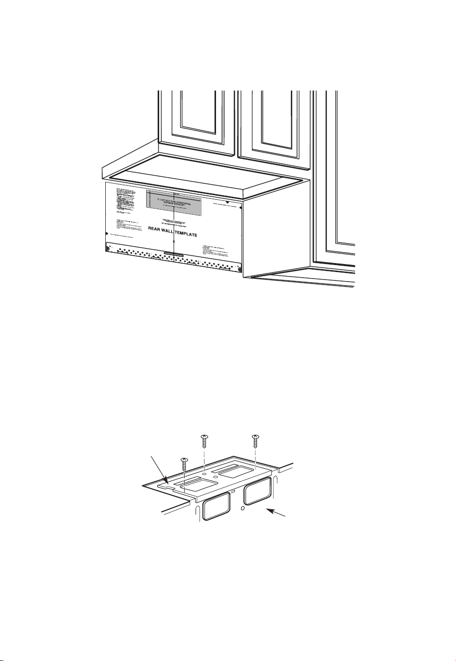
FR-34
B1. PRÉPARATION DE LA PAROI ARRIÈRE POUR L'ÉCHAPPEMENT ARRIÈRE
EXTÉRIEUR
Vous devez découper une ouverture dans la paroi arrière pour l'échappement extérieur.
1. Lisez les consignes relatives au MODÈLE DE MUR ARRIÈRE. Collez-le au mur arrière.
2. Découpez l'ouverture en suivant les consignes relatives au MODÈLE DE MUR ARRIÈRE.
B2. RETIRER LA PLAQUE DU SOUFFLEUR
Retirez et conservez la vis qui maintient la plaque du souffleur au micro-ondes. Soulevez
la plaque du souffleur.
Plaque de
soufflage
Arrière du
micro-ondes
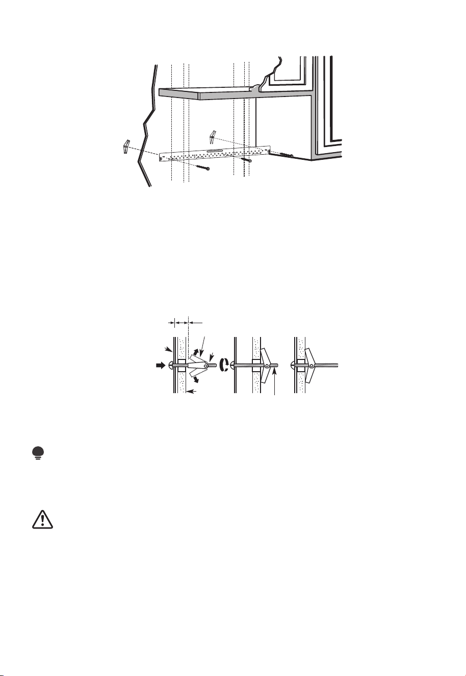
FR-35
B3. FIXEZ LA PLAQUE DE MONTAGE AU MUR
Fixez la plaque au mur à l'aide de boulons à genouillère. Au moins une vis à bois doit être
utilisée pour fixer la plaque à un poteau mural.
1. Retirez les ailettes à genouillère des boulons.
2. Insérez les boulons dans la plaque de montage à travers les trous destinés à pénétrer
dans la cloison sèche et fixez à nouveau les ailettes à genouillère à 3⁄4po (19 mm) sur
chaque boulon.
Pour utiliser les boulons à genouillère:
Espacement pour les
bascules de plus de
l'épaisseur du mur
Ailettes à genouillère
Boulon à
genouillère
Mur
Plaque de
montage
Extrémité du boulon
3. Placez la plaque de montage contre le mur et insérez les ailettes à genouillère dans les
trous du mur pour monter la plaque.
REMARQUE:
Avant de serrer les boulons à genouillère et la vis à bois, assurez-vous que le bas de la
plaque de montage touche le bas de l'armoire lorsqu'il est poussé contre le mur et que la
plaque est correctement centrée sous l'armoire.
MISE EN GARDE :
Veillez à éviter de pincer les doigts entre l'arrière de la plaque de montage et le mur.
4. Serrez tous les boulons. Retirez la plaque du mur pour aider à serrer les boulons.
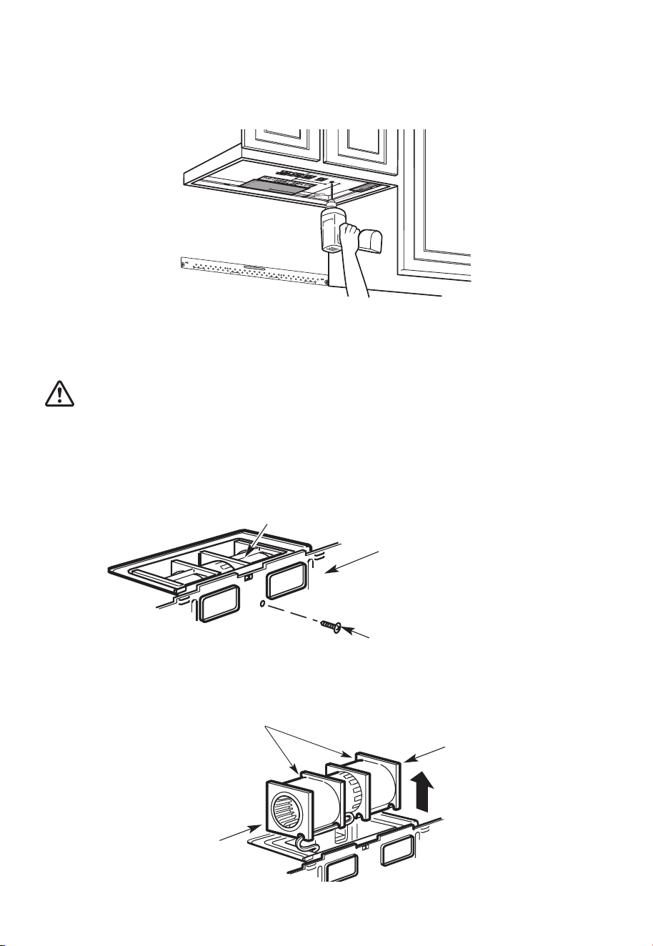
FR-36
B4. UTILISER LE MODÈLE D'ARMOIRE SUPÉRIEURE POUR LA PRÉPARATION
DE L'ARMOIRE SUPÉRIEURE
Vous devez percer des trous pour les vis du support supérieure et un trou suffisamment
grand pour que le cordon d'alimentation s'y insère.
1. Lisez les consignes relatives au MODÈLE D'ARMOIRE SUPÉRIEUR.
2. Collez-le sous l'armoire supérieure.
3. Percez les trous en suivant les consignes relatives au MODÈLE D'ARMOIRE SUPÉRIEUR.
MISE EN GARDE :
Portez des lunettes de sécurité lorsque vous percez des trous dans le fond de l'armoire.
B5. ADAPTATION DU SOUFFLEUR À MICRO-ONDES POUR L'ÉCHAPPEMENT
ARRIÈRE EXTÉRIEUR
1. Retirez et conservez la vis qui maintient le moteur du souffleur au micro-ondes.
Moteur du souffleur
Arrière du micro-ondes
Vis du moteur du souffleur
2. Retirez délicatement l'unité de soufflage. Les câbles s'étendront suffisamment loin
pour vous permettre de régler l'unité de soufflage.
Avant: Ouvertures des
pales de ventilateur
orientées vers l'avant
Extrémité B
Extrémité A

FR-37
3. Faites rouler l'unité de soufflage à 90°
Avant la rotation
Arrière du
micro-ondes
Arrière du
micro-ondes
Après la rotation
4. Tournez l'unité de soufflage dans le sens inverse des aiguilles d'une montre à 180°.
Avant la rotation
Après la rotation
Arrière du
micro-ondes
Arrière du
micro-ondes
5. Retirez délicatement les câbles des rainures. Réacheminez les câbles à travers les
rainures de l'autre côté de l'unité de soufflage.
Avant la rotation
Câbles acheminés
par le côté droit
Câbles acheminés
par le côté gauche
Après la rotation
6. Tournez l'unité de soufflage à 90° de sorte que les ouvertures des pales du ventilateur
soient orientées vers l'arrière du micro-ondes.
Avant le roulage
Après le roulage
Arrière du
micro-ondes
Arrière du
micro-ondes
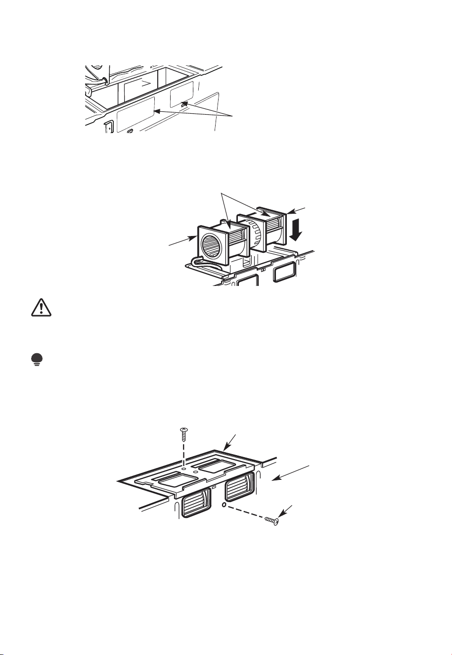
FR-38
7. Retirez les plaques défonçables à l'arrière de l'appareil à l'aide des pinces à découper.
(pour certains modèles)
Plaques de déblocage:
Coupez les 4 toiles sur chaque
panneau de déblocage et retirez
les déblocages métalliques
pour le flux d'air arrière. Veuillez
prendre soin d'enlever les bords
tranchants créés par le retrait
des plaques de déblocage.
Arrière du micro-ondes
8. Replacez l'unité de soufflage dans l'ouverture.
APRÈS : Ouvertures des pales de
ventilateur orientées vers l'arrière
Extrémité A
Extrémité B
MISE EN GARDE :
Ne tirez ni n'étirez le câblage de l'unité de soufflage. Assurez-vous que les câbles ne sont
pas pincés et qu'ils sont correctement fixés.
REMARQUE:
Les ouvertures d'échappement de l'unité de soufflage doivent correspondre aux
ouvertures d'échappement à l'arrière du four à micro-ondes.
9. Fixez l'unité de soufflage au micro-ondes avec la vis d'origine.
Plaque de soufflage
Arrière du
micro-ondes
Vis du moteur
du souffleur
10. Remettez la plaque du souffleur dans la même position qu'auparavant avec la vis.
Assurez-vous que la vis est bien serrée.
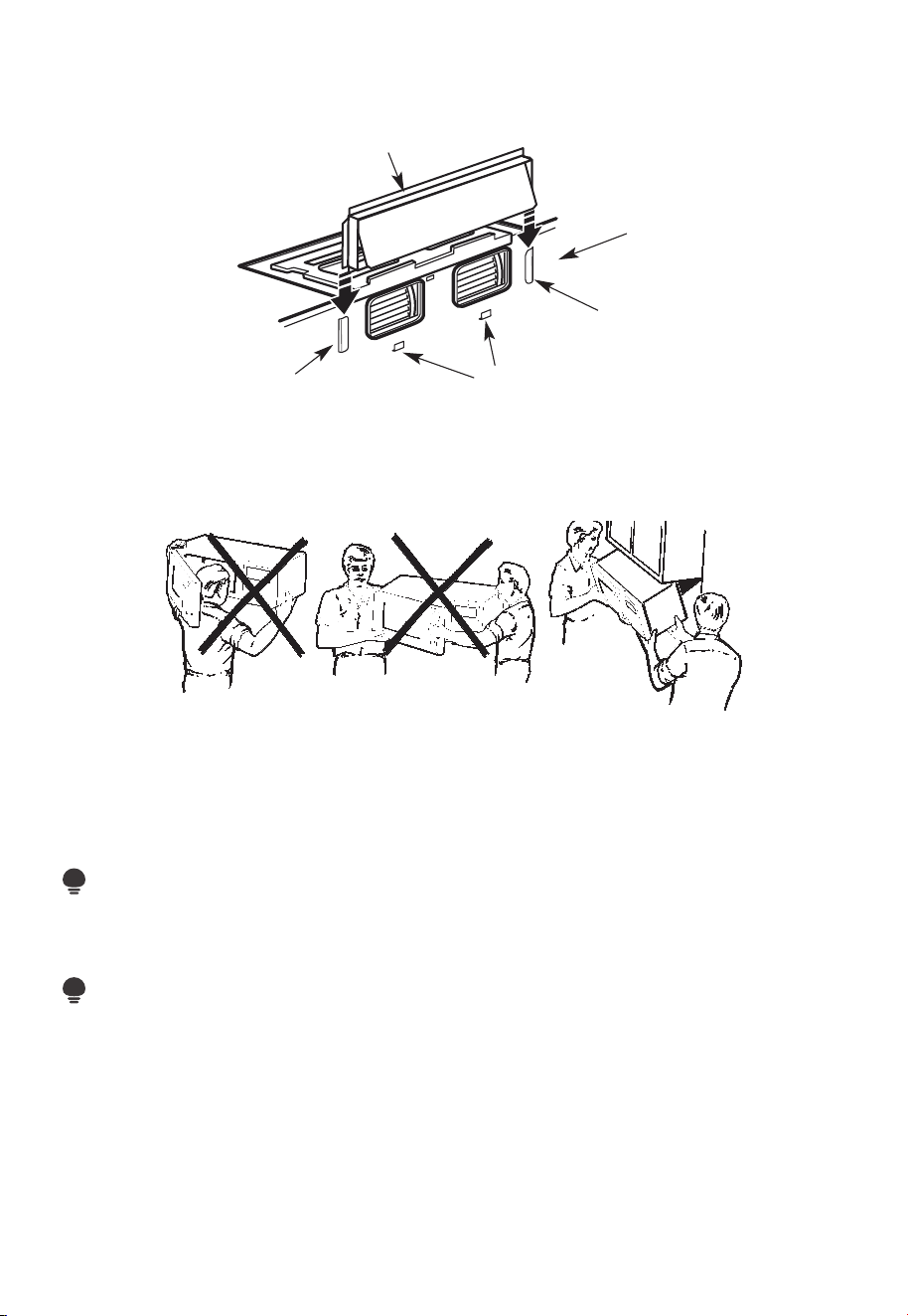
FR-39
11. Fixez l'adaptateur d'échappement à l'arrière du four en le glissant dans les guides
situés en haut au centre de l'arrière du four.
Adaptateur
Arrière du
micro-ondes
Guide
Onglets de verrouillage
Guide
Poussez fermement jusqu'à ce qu'il soit dans les languettes de verrouillage inférieures.
Veillez à ce que la charnière de l'amortisseur soit installée de manière à ce qu'elle soit en
haut et que l'amortisseur oscille librement.
B6. MONTER LE FOUR À MICRO-ONDES
POUR FACILITER L'INSTALLATION ET PROCURER LA SÉCURITÉ PERSONNELLE, NOUS
VOUS RECOMMANDONS QUE DEUX PERSONNES INSTALLENT CE FOUR À MICRO-
ONDES.
IMPORTANT: Ne saisissez pas et n'utilisez pas la poignée ou le bouclier thermique
pendant l'installation. Ne retirez pas les entretoises en carton entre le bouclier thermique
et la porte.
REMARQUE:
Si votre armoire est en métal, utilisez l'œillet en nylon autour du trou du cordon
d'alimentation pour éviter de couper celui-ci.
REMARQUE:
Nous vous recommandons d'utiliser des blocs de remplissage de la façade de l'armoire
suspendus sous l'étagère inférieure de celle-ci.
IMPORTANT: Si les blocs de remplissage ne sont pas utilisés, des vis de serrage
excessives peuvent endommager le boîtier.
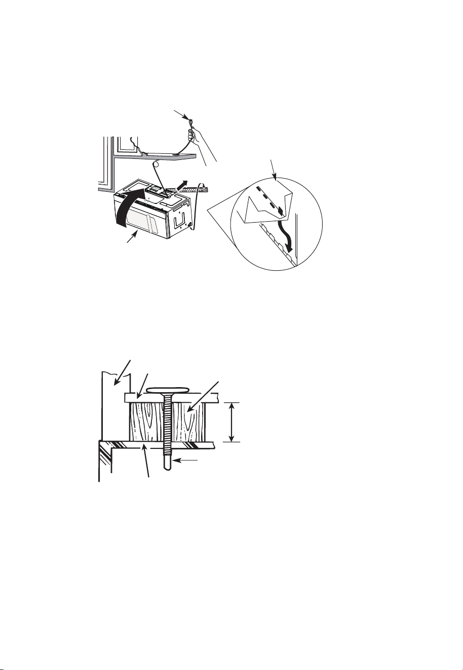
FR-40
REMARQUE: Lors du montage
du four à micro-ondes, enfilez le
cordon d'alimentation à travers
le trou situé au bas de l'armoire
supérieure. Gardez-le bien serré
tout au long des étapes 1 à 3.
Ne pincez pas le cordon ou ne
soulevez pas le four en tirant sur
le cordon.
1. Soulevez le micro-ondes,
inclinez-le vers l'avant et
accrochez les fentes du bord
inférieur arrière sur quatre
languettes inférieures de la
plaque de montage.
2. Tournez l'avant du four contre
le fond de l'armoire.
3. Insérez la vis à alignement automatique à travers le trou central supérieur de l'armoire.
Fixez temporairement le four en tournant la vis d'au moins deux tours complets après
l'engagement des fils (elle sera complètement serrée plus tard). Assurez-vous de
garder le cordon d'alimentation serré. Veillez à ne pas pincer le cordon, en particulier
lors du montage affleurant au bas de l'armoire.
Façade de l'armoire
Étagère inférieure de l'armoire
Bloc de remplissage
Équivalent à la profondeur de
l'encastrement de l'armoire
Vis à alignement
automatique
Dessus du four à micro-ondes
4. Fixez le four à micro-ondes à l'armoire supérieure.
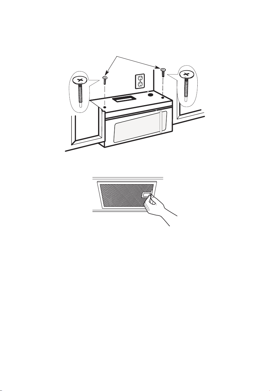
FR-41
5. Insérez 2 vis à alignement
automatique à travers
les trous extérieurs de
l'armoire supérieure.
Tournez deux tours
complets sur chaque vis.
6. Serrez les deux vis extérieures au sommet du four à micro-ondes. (Tout en serrant les
vis, maintenez le four à micro-ondes en place contre le mur et l'armoire supérieure.)
7. Installez des filtres à graisse. Consultez le Guide relatif à l'utilisation et l'entretien fourni
avec le micro-ondes pour plus d'informations.
C. RECIRCULATION (sans conduit de ventilation)
APERÇU DE L'INSTALLATION
C1. Fixez la plaque de montage au mur
C2. Préparez l'armoire supérieure
C3. Vérifiez la plaque du souffleur
C4. Monter le four à micro-ondes
C5. Installez ou changez le filtre à charbon

FR-42
12
"
4"
R
N
O
EA
T
D
E
:
A
IT
N
I
D F
S VE
O
L
R
L
Y
O
I
W
MP
T
O
H
E
R
T
D
A
I
R
N
E
T
C
T
T
I
O
O
IN
T
H
E
IN
ST
ALL
AT
I
O
N
I
N
ST
R
U
CTI
O
N
N
S
S
BEF
ORE
PR
O
C
EE
D
INGW
IT
H
T
HI
S
REAR W
ALL
TEM
P
L
AT
E
.
T
e
mp
l
ate
se
rv
e
s t
o
p
mo
t
U
u
le
s
n
t
e
.
ti
1
o
.
u
Th
i
s Re
n
a
g
r
pl
W
a
a
te
l
l
an
d
to
l
o
c
a
t
h
t
e
eh
o
r
i
z
o
o
sit
n
t
i
o
a
l
n
e
t
x
h
h
e
a
b
u
s
ot
t
t
o
m
et
oche
c
k
t
h
a
t
t
h
e
t
emp
l
a
t
e is
p
osition
d
L
oc
ou
n
t
i
n
AN
T:
I
m
MPO
R
T
E
AT
L
at
e
a
g
n
d
pl
a
m
te
a
.
r
k hol
es to
a
lig
n
w
i
t
h hol
e
s
in
t
h
e
LOC
AT
NT
ER
L
E
IN
AS
E
.
T
O
NESTUD
O
N
E
I
T
H
E
R
SID
E
OF
T
H
E
CE
HEL
O
CA
T
I
SP
ACE
AREA.
MARK
T
D
TO
G
GLE
B
O
OL
N F
TS
O
I
R
N
2
T
A
H
D
E
DI
M
T
O
IO
U
N
N
T
AL
I
N
,
E
G
V
P
E
L
N
AT
LY
E
o
unt
i
n
:
L
o
c
a
t
e
a
g
n
d
p
lat
ma
e
.
rk holes t
o
a
l
i
gn
w
i
t
h
h
ol
es
in
t
h
e
I
m
M
P
O
RT
E
A
N
A
T
T
L
LO
C
AT
NT
E
RL
E
I
A
NE
ST
.
O
N
ESTUD
O
N EI
TH
E
R S
IDE
O
F
THECE
H
E
LOCAT
I
SPA
C
A
RE
A
.
MARK
ED
T
T
O
GG
LE
BO
ON
F
L
T
S
OR
IN
2
T
A
H
D
E
DIT
M
O
IO
U
N
N
A
T
I
L
,
N
E
G
VE
P
L
A
NL
T
Y
E
T
r
im
t
h
e
rear
w
a
l
l te
m
p
lat
e
a
lon
g
t
he
d
o
t
ted
l
in
e.
3
/8
"
TO
EDG
E
Trim the re
ar
wall t
em
pla
t
e alongthe dotte
d l
in
e.
L
a
o
c
c
c
a
u
a
t
r
e
a
t
lev
a
el
n
y
e
d
.
l
2
.
m
a
r
k
at
l
ea
st o
nes
tud
on
t
he l
ef
t
o
r
rig
h
t
s
i
de
o
f
the
c
en
te
rl
i
ne
.
It
a
t
rop
mi
s
i
nt
t
o
u
s
e
a
t
l
e
asto
n
e w
o
od
n
t
w
e
a
v
d
f
e
i
.
rm
M
ly
a
r
i
k
n
t
a
w
s
o
t
u
a
d
d
d
t
i
o
t
i
o
s
n
u
a
p
l,
p
o
e
r
v
t
e
t
h
n
e
ly
w
s
p
ei
a
g
h
c
e
t
d
o
o
r
s
i
t
h
nt
e s
h
u
e
p
m
p
l
a
i
r
e
d
ke
t
d
o
l
g
o
g
c
l
a
e
t
b
io
o
l
n
t
s
s
.
.
W
here
th
e
r
e
i
s
l
s
3
o
f
o
.
c
r
c
t
t
t
a
D
a
e
h
h
o
t
r
i
e
s
w
g
a
i
l
o
t
t
l
g
u
n
m
l
m
d
ho
d
s
i
e
o
o
,
c
r
f
l
u
d
e
ril
l
a
3
/16"
h
o
le
fo
r
wood sc
re
w
s
.
F
orho
l
e
s
n ne u
p
with
a
s
tu
d
,
d
r
i
ll5
/8
"
h
o
l
e
sf
o
r
o
l
t
t
N
s.
l
i
OD
bo
TI
NSTALL
TH
E
M
OU
NTI
N
GPL
A
TE
AT
R
T
HI
m
S
v
e
TI
O
M
E.
4
.
e
o
t
h
e
te
m
p
lat
e
f
ro
m
t
h
e
rea
r
wa
ll.
5
.
Re
vie
wth
e
In
s
t
all
a
t
i
on
In
s
t
ruct
i
o
n
b
ook f
or
y
ou
r
in
s
t
a
l
lat
io
n
s
i
t
ua
t
i
o
n.
Darlev
ue
l
ta
a
l
a
ho
ja
pa
r
acons
u
ltar
la
v
e
r
s
ión
e
nEspañol.
REMARQUES IMPORTANTES :
1. Assurez-vous que les vis du moteur du souffleur et de la plaque du souffleur sont bien
serrées lors de leur réinstallation. Cela aidera à éviter les vibrations excessives.
2. Assurez-vous que le câblage du moteur a été correctement acheminé et sécurisé et
que les câbles ne sont pas pincés.
C1. FIXEZ LA PLAQUE DE MONTAGE AU MUR
Fixez la plaque au mur à l'aide de boulons à genouillère. Au moins une vis à bois doit être
utilisée pour fixer la plaque à un poteau mural.
Si la profondeur de l'armoire, y compris les portes de l'armoire, est supérieure à 13po,
l'unité doit être espacée du mur à l'aide de matériaux adéquats prenant en charge 150 lb
pour permettre un échappement/admission d'air par le haut appropriée.
Armoire Armoire
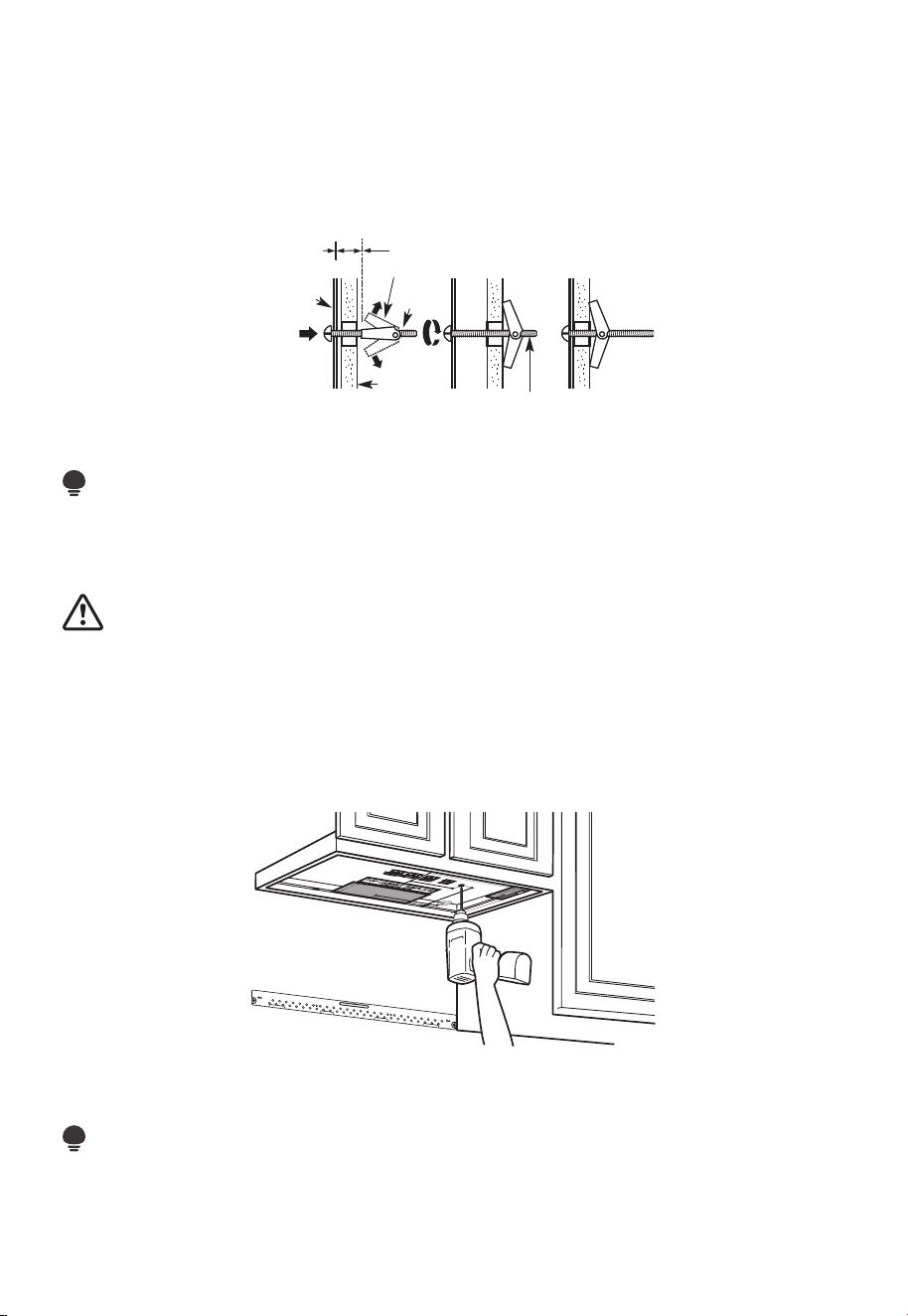
FR-43
1. Retirez les ailettes à genouillère des boulons.
2. Insérez les boulons dans la plaque de montage à travers les trous destinés à entrer
dans la cloison sèche et fixez à nouveau les ailettes à genouillère de 3/4po à (19 mm)
sur chaque boulon.
Pour utiliser les boulons à genouillère:
Espacement pour les
bascules de plus de
l'épaisseur du mur
Ailettes à genouillère
Boulon à
genouillère
Mur
Plaque de
montage
Extrémité du boulon
3. Placez la plaque de montage contre le mur et insérez les ailettes à genouillère dans les
trous du mur pour monter la plaque.
REMARQUE:
Avant de serrer les boulons à genouillère et la vis à bois, assurez-vous que le bas de la
plaque de montage touche le bas de l'armoire lorsqu'il est poussé contre le mur et que la
plaque est correctement centrée sous l'armoire.
MISE EN GARDE :
Veillez à éviter de pincer les doigts entre l'arrière de la plaque de montage et le mur.
4. Serrez tous les boulons. Retirez la plaque du mur pour aider à serrer les boulons.
C2. UTILISER LE MODÈLE D'ARMOIRE SUPÉRIEURE POUR LA PRÉPARATION
DE L'ARMOIRE SUPÉRIEURE
Vous devez percer des trous pour les vis de support supérieures et un trou suffisamment
grand pour que le cordon d'alimentation s'y insère.
1. Lisez les consignes relatives au MODÈLE D'ARMOIRE SUPÉRIEUR.
2. Collez-le sous l'armoire supérieure.
REMARQUE:
Réglez le modèle supérieur en conséquence si le micro-ondes est espacé du mur en
raison de la profondeur de l'armoire (y compris les portes d'armoire) de plus de 13po.
Percez les trous en suivant les consignes relatives au MODÈLE D'ARMOIRE SUPÉRIEUR.
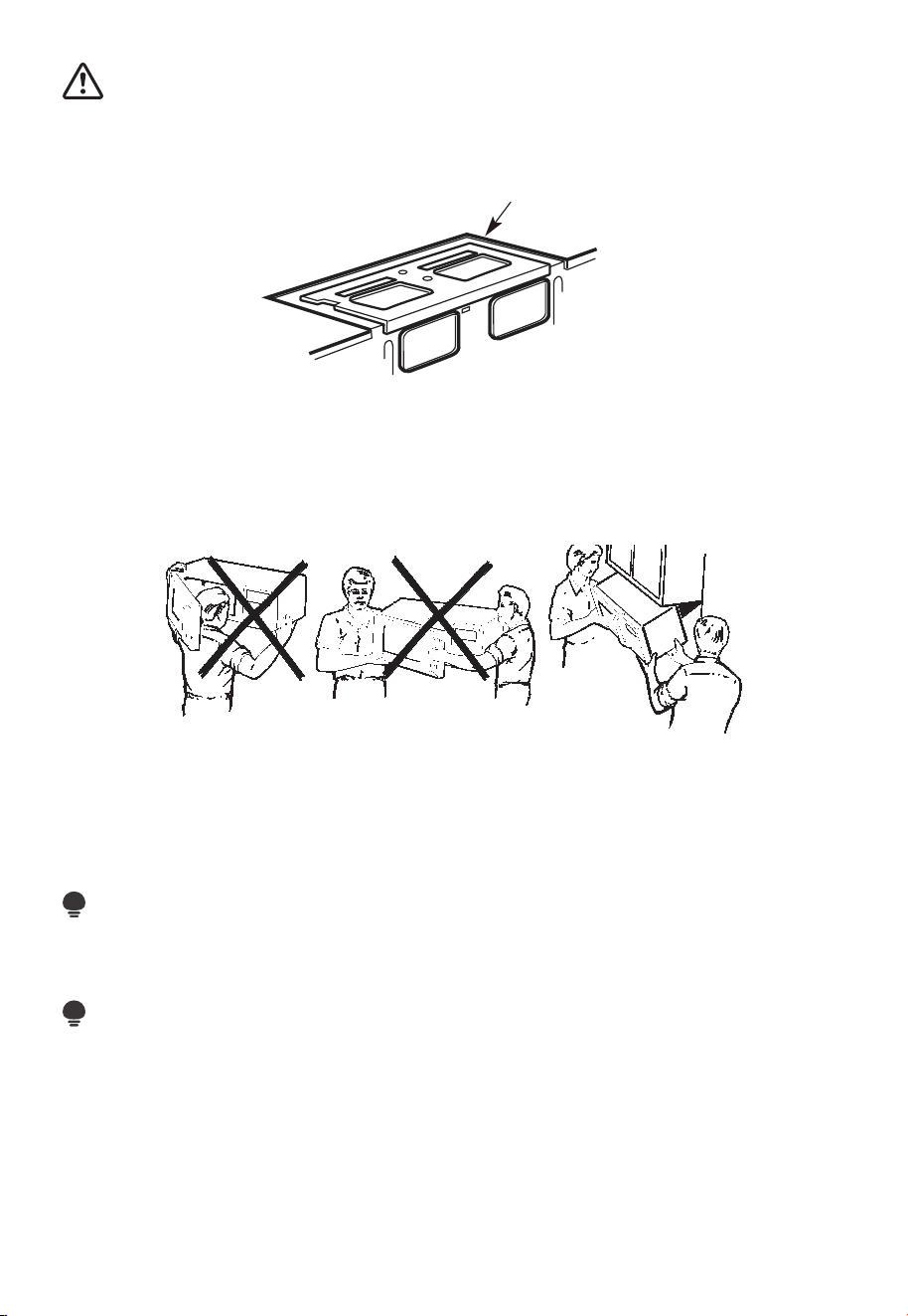
FR-44
MISE EN GARDE :
Portez des lunettes de sécurité lorsque vous percez des trous dans le fond de l'armoire.
C3. VÉRIFIEZ LA PLAQUE DU SOUFFLEUR
Plaque de soufflage
Placez le micro-ondes en position verticale, avec la partie supérieure de l'appareil
orientée vers le haut.
Vérifiez que la plaque du souffleur est correctement installée sur l'appareil.
C4. MONTER LE FOUR À MICRO-ONDES
POUR FACILITER L'INSTALLATION ET PROCURER LA SÉCURITÉ PERSONNELLE, NOUS
VOUS RECOMMANDONS QUE DEUX PERSONNES INSTALLENT CE FOUR À MICRO-
ONDES.
IMPORTANT: Ne saisissez pas et n'utilisez pas la poignée ou le bouclier thermique
pendant l'installation. Ne retirez pas les entretoises en carton entre le bouclier thermique
et la porte.
REMARQUE:
Si votre armoire est en métal, utilisez l'œillet en nylon autour du trou du cordon
d'alimentation pour éviter de couper celui-ci.
REMARQUE:
Nous vous recommandons d'utiliser des blocs de remplissage si la façade de l'armoire est
suspendue sous l'étagère inférieure de celle-ci.
IMPORTANT: Si les blocs de remplissage ne sont pas utilisés, un endommagement du
boîtier peut survenir à cause de vis de serrage excessives.
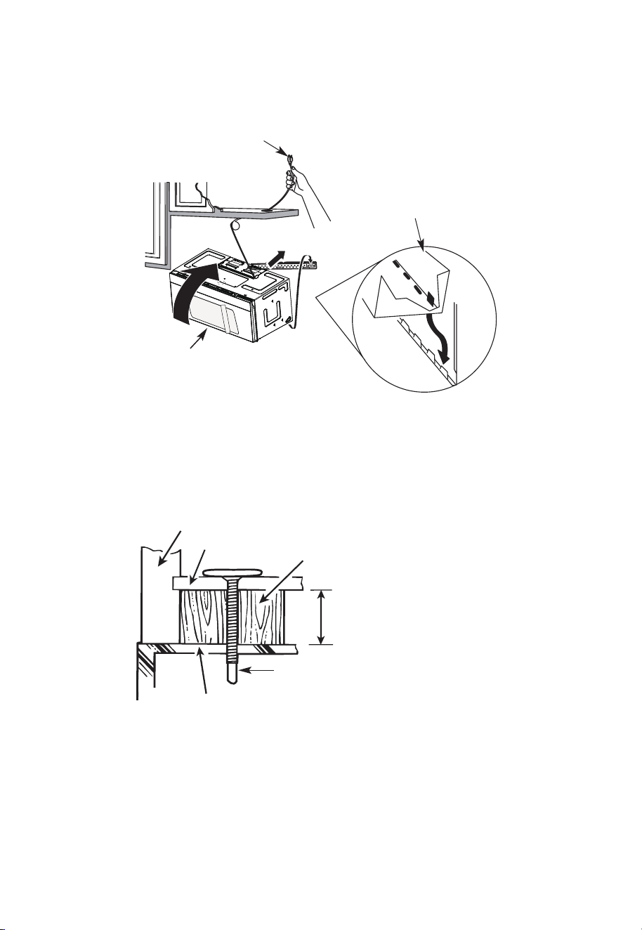
FR-45
REMARQUE: Lors du montage du
four à micro-ondes, enfilez le cordon
d'alimentation à travers le trou situé
au bas de l'armoire supérieure.
Gardez-le bien serré tout au long des
étapes 1 à 3. Ne pincez pas le cordon
ou ne soulevez pas le four en tirant
sur le cordon.
2. Tournez l'avant du four
contre le fond de l'armoire.
1. Soulevez le micro-
ondes, inclinez-le vers
l'avant et accrochez
les fentes du bord
inférieur arrière sur
quatre languettes
inférieures de la plaque
de montage.
3. Insérez une vis à alignement automatique dans le trou central supérieur de l'armoire.
Fixez temporairement le four en tournant la vis d'au moins deux tours complets après
l'engagement des fils (Il sera complètement serré plus tard.) Assurez-vous de garder
le cordon d'alimentation serré. Veillez à ne pas pincer le cordon, en particulier lors du
montage affleurant au bas de l'armoire.
Façade de l'armoire
Étagère inférieure de l'armoire
Bloc de remplissage
Équivalent à la profondeur de
l'encastrement de l'armoire
Vis à alignement automatique
Dessus du four à micro-ondes
4. Fixez le four à micro-ondes à l'armoire supérieure.
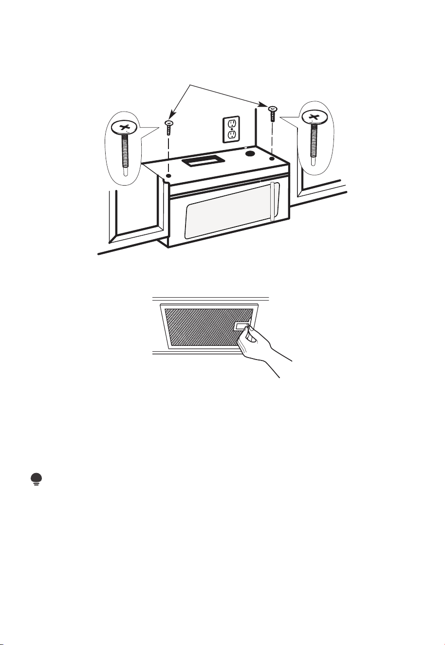
FR-46
5. Insérez 2 vis à alignement
automatique à travers les
trous extérieurs de l'armoire
supérieure. Tournez deux tours
complets sur chaque vis.
6. Serrez les deux vis extérieures au sommet du four à micro-ondes. (Tout en serrant les
vis, maintenez le four à micro-ondes en place contre le mur et l'armoire supérieure.)
7. Installez des filtres à graisse. Voir le guide relatif à l'utilisation et à l'entretien emballé
avec le micro-ondes.
C5. INSTALLATION OU CHANGEMENT DU FILTRE À CHARBON (certains
modèles)
REMARQUE:
Le filtre à charbon est installé en usine dans certains modèles. Reportez-vous au Guide
d'utilisation et d'entretien pour voir si le vôtre est installé en usine et pour obtenir des
informations sur le remplacement.
Pour les modèles sans porte d'accès au filtre de recirculation, suivez les étapes suivantes
pour remplacer ou installer un filtre à charbon :
1. Débranchez le four à micro-ondes ou débranchez l'alimentation.
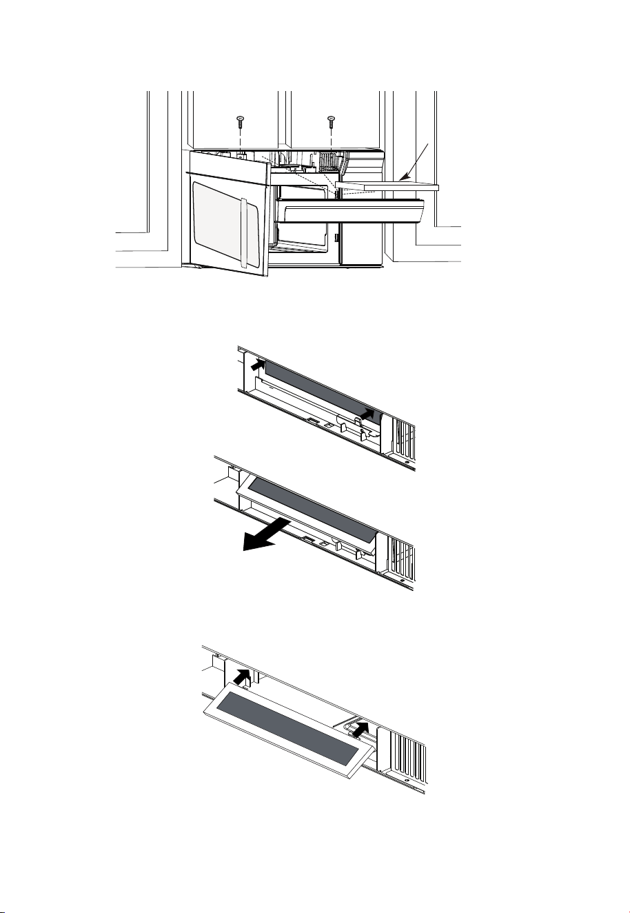
FR-47
2. Ouvrez la porte du four à micro-ondes et retirez les deux vis de fixation de l'évent
situées sur le dessus du four à micro-ondes à l'aide d'un tournevis Phillips n°1.
Filtre à
charbon
3. Retirez le filtre à charbon en poussant le haut du filtre vers l'intérieur,puis tirez-le vers
l'avant hors de l'appareil.
4. Faites glisser le haut du nouveau filtre à charbon dans le haut de la cavité du filtre.
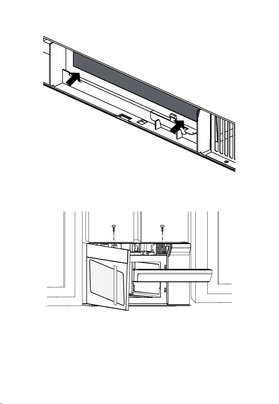
FR-48
5. Appuyez sur le bas du filtre à charbon pour le placer dans la bonne position.
6. Réinstallez l'évent en faisant glisser le fond de celui-ci en place. Poussez le haut de
l'évent en position et glissez-le en place. Remplacez les deux vis de fixation de l'évent
situées sur le dessus du micro-ondes à l'aide d'un tournevis Phillips n°1.
7. Fermez la porte du micro-ondes. Branchez le four à micro-ondes ou rebranchez
l'alimentation.
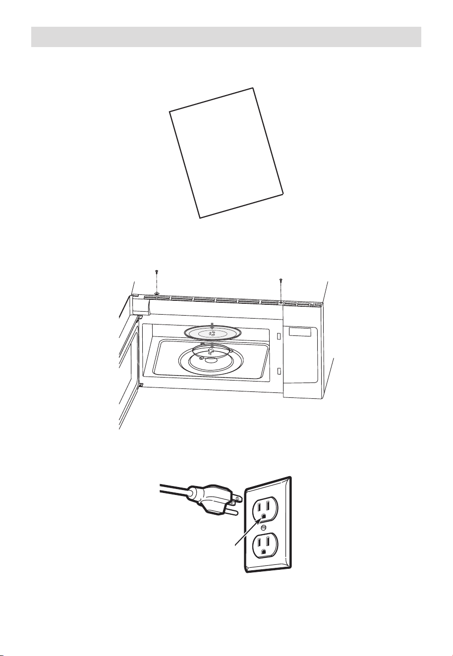
FR-49
Avant d'utiliser votre micro-ondes
1. Assurez-vous que le four à micro-ondes a été installé conformément aux consignes.
USER
MANUAL
MANUEL
D’UTILISATION
2. Retirez tout le matériel d'emballage du four à micro-ondes.
3. Installez l'écrou de la plaque tournante et du plateau en verre dans la cavité.
4. Branchez le cordon d'alimentation dans une prise électrique séparée et dédiée de 15 à
20 ampères.
Assurez-vous que
la mise à la terre
est correcte avant
l'utilisation

FR-50
5. Remplacez le fusible de la maison ou rallumez le disjoncteur.
6. Lisez le manuel d'utilisation.
USER
MANUAL
MANUEL
D’UTILISATION
7. CONSERVEZ LE MANUEL D'UTILISATION POUR L'UTILISATION DE L'INSPECTEUR
LOCAL.
USER
MANUAL
MANUEL
D’UTILISATION
Contrôle de fonctionnement
1. Assurez-vous que l'appareil a été installé conformément à ces consignes.
2. Retirez tous les matériaux d'emballage du four.
3. Remplacez le fusible de la maison ou rallumez le disjoncteur.
4. Branchez le cordon d’alimentation dans la prise de courant.
5. Lisez les consignes d'utilisation avant de tester le produit.
6. Allumez le ventilateur d'échappement à la vitesse Turbo et confirmez qu'il fonctionne
à l'aide d'un mouchoir (il adhérera au filtre).
7. Vérifiez que le clapet d'échappement extérieur s'est ouvert.
8. Réglez le four à micro-ondes pendant 1 minute et confirmez que le four fonctionne
normalement à l'aide d'une tasse d'eau.
9. Conservez ces consignes d'installation à l'intention de l'inspecteur local en électricité.
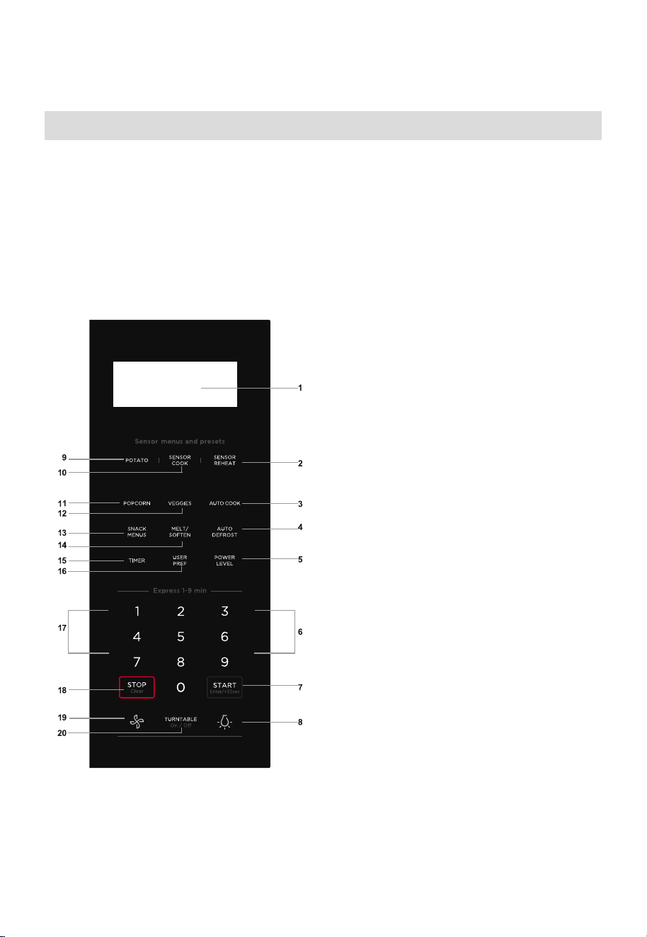
FR-51
CONSIGNES D’UTILISATION
Panneau de commande
(1) Écran :
L’affichage comprend une horloge et des indicateurs
qui indiquent l’heure, les réglages du temps de cuisson,
les puissances de cuisson, le capteur, les quantités, les
poids et les fonctions de cuisson sélectionnées.
(2) Sensor Reheat (5 differents réglages)
(3) Auto Cook
(4) Auto Defrost
(5) Power Level (11 niveaux de puissance
disponibles)
(6) Numeric pads (0 à 9)
(7) START +30 sec
(8) Surface Light (fort/faible/éteint)
~ Utilisez ces touches pour régler la luminosité
des éclairages de surface.
(9) Potato (1-4 pommes de terre)
(10) Sensor cook
(11) Popcorn
(12) Veggies
(13) Snacks
(14) Melt Soften
(15) Timer (allumé-éteint)
(16) User pref
(17) Quick Start ( 9 réglages de touche instantanés)
(18) Arrêt/Effacer
(19) Exhaust (High/Low/Off) ~ Permet d’arrêter le
ventilateur d’extraction ou de régler la vitesse
du ventilateur.
(20) Turntable (allumé-éteint)
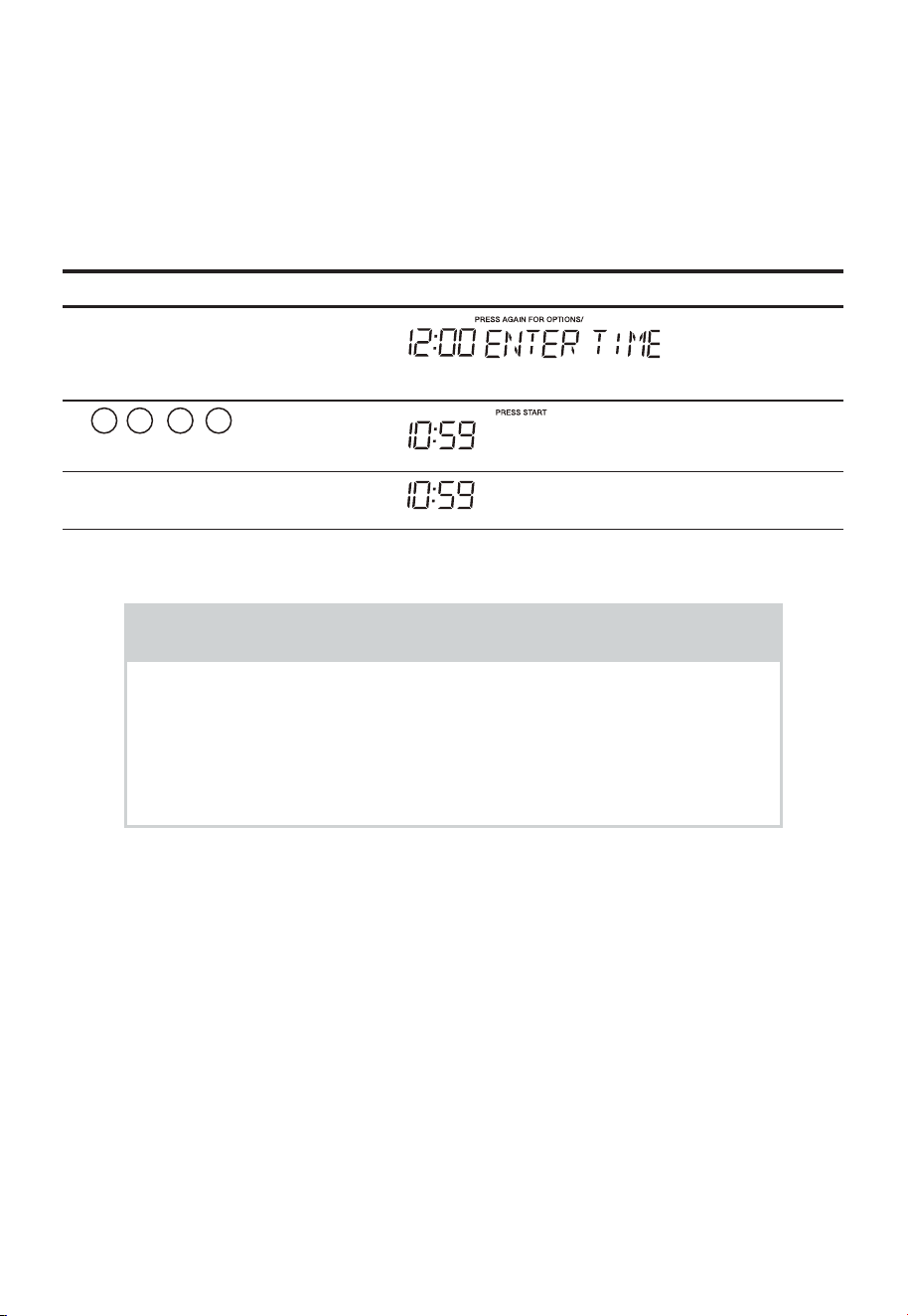
FR-52
•
• L’horloge peut être désactivée lorsque le four à micro-ondes est branché pour la
première fois et que le bouton Stop/Clear est sélectionné. Pour réactiver l’horloge,
suivez les instructions données par l’horloge.
Réglage de l’horloge
• Supposons que vous souhaitez saisir l’heure correcte de la journée
10:59
Touchez : L’écran affiche :
1. User pref
2.
1 0 5
9
3. «Start/Enter/+30 Sec»
REMARQUE
1. Vous ne pouvez pas entrer une heure incorrecte (ex. 2:89), le
8 est un chiffre non valide et ne peut pas être entré. Entez l’heure
correcte.
2. Si vous touchez à «Stop/Clear» pendant le réglage de l’heure,
l’écran affichera la dernière heure réglée du jour ou un affichage
vide si aucune heure n’a été réglée.
CUISSON MANUELLE
Cuisson chronométrée
Votre four à micro-ondes peut être programmé pour 99 minutes
99secondes (99:99). Entrez toujours les secondes après les minutes,
même si elles sont toutes les deux nulles.
• Supposons que vous souhaitez cuire pendant 5 minutes, 30 secondes
à 100% de puissance,
Avant d'utiliser votre nouveau four, assurez-vous de lire et de comprendre complètement
ce MANUEL D'UTILISATION.
Lorsque le four est branché sur une prise, veuillez sauter cette étape.( )
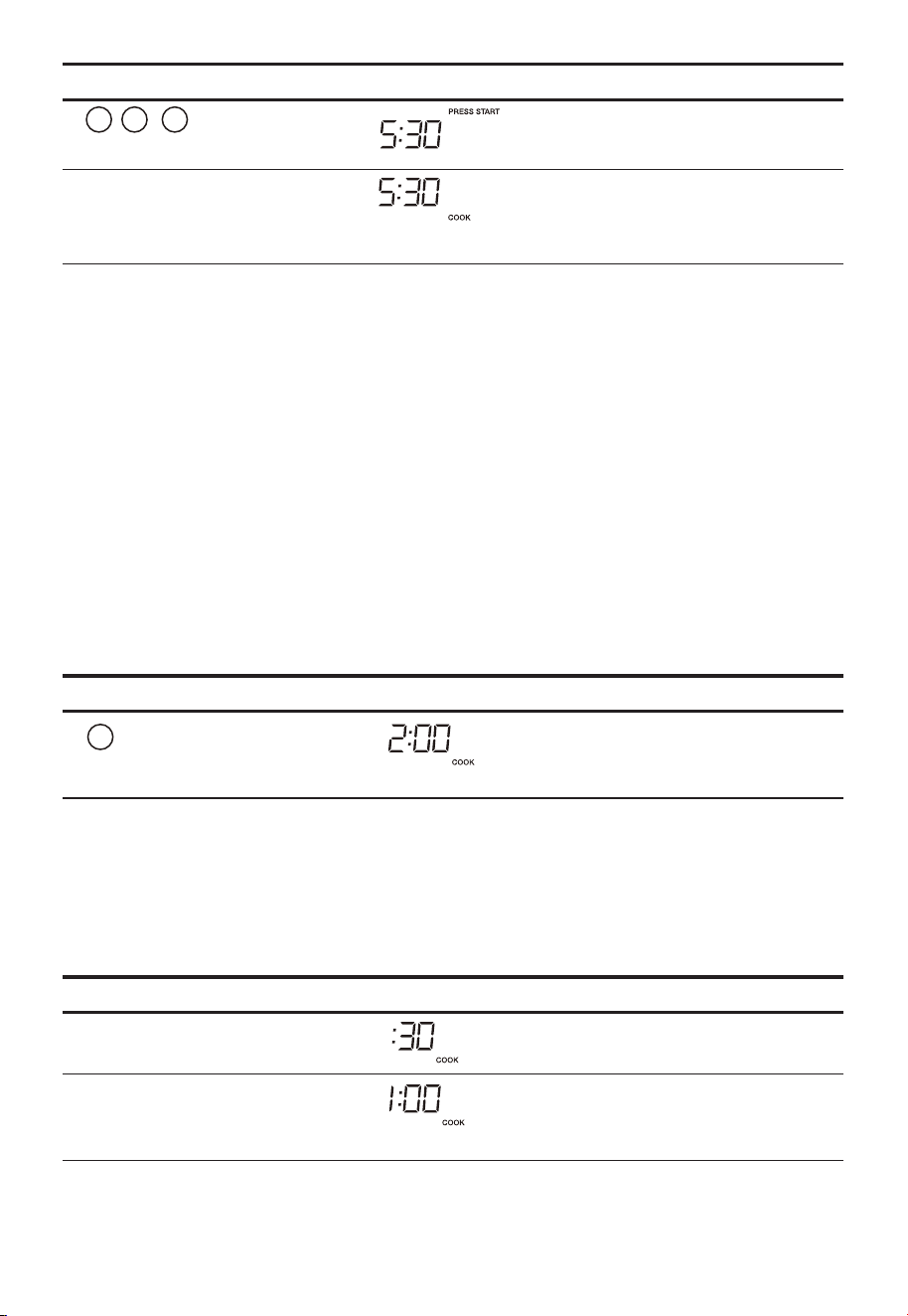
FR-53
Touchez : L’écran affiche :
1.
5 3 0
2.
«Start/Enter/+30 Sec»
Compte à rebours
Interrompre la cuisson
Vous pouvez arrêter le four pendant un cycle en ouvrant la porte. Le
four cesse de chauffer et le ventilateur s'éteint, mais le voyant reste
allumé.
Pour redémarrer la cuisson, fermez la porte et touchez à «Start/
Enter/ +30 Sec .
Si vous ne souhaitez pas poursuivre la cuisson, ouvrez la porte et
touchez «Stop Clear»
Utilisation de One Touch Start (démarrage instantané)
La touche numérique 1~9 peut être touchée pour une fonction de
démarrage automatique de la cuisson de 1~9 minutes.
Il s’agit d’une touche permettant de gagner du temps qui lance
automatiquement la cuisson 2 secondes après la sélection.
Touchez : L’écran affiche :
1.
2
Compte à rebours
Utilisation de Add 30 Sec.
C’est une touche qui permet de gagner du temps. Il s’agit d’une
fonction simplifiée vous permettant de régler et de démarrer
rapidement la cuisson au four à micro-ondes à 100% de puissance.
• Supposons que vous vouliez cuisiner pendant une minute.
Touchez : L’écran affiche :
1.
«Start/Enter/+30 Sec»
2.
«Start/Enter/+30 Sec»
Compte à rebours
»
/
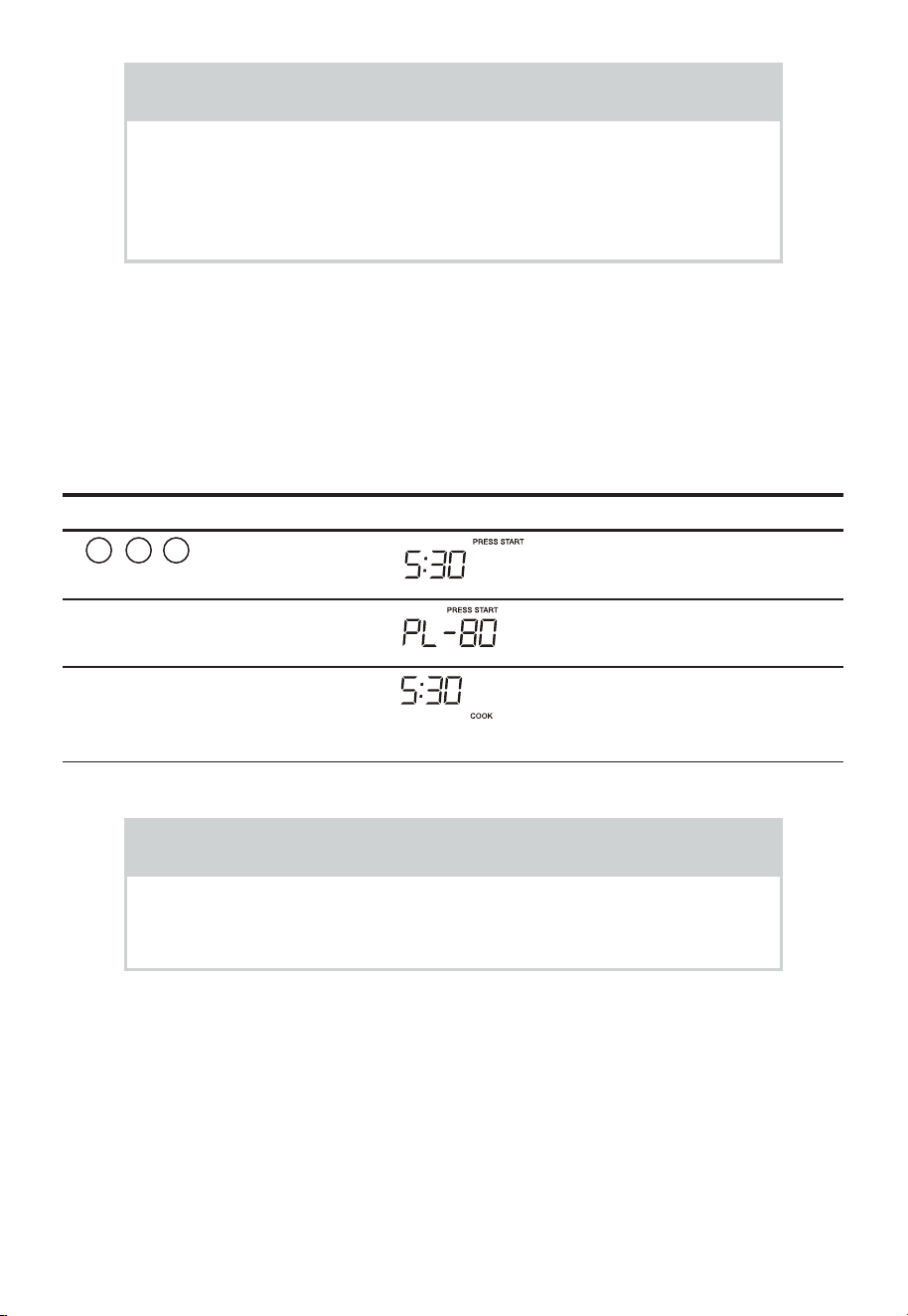
FR-54
REMARQUE
«Food» s’affiche si un cycle de cuisson à démarrage rapide
ou la touche +30 sec n’est pas sélectionnée dans les 5 minutes
suivant le l’introduction des aliments dans le four à micro-
ondes. Vous devez ouvrir puis refermer la porte pour effacer
«Food» de l’écran.
Réglage de la cuisson minutée avec un niveau de puissance
Cette fonction vous permet de programmer un temps et une puissance
de cuisson spécifiques. Pour obtenir les meilleurs résultats, il existe
10 réglages de niveau de puissance en plus de la puissance élevée
(100%).
• Supposons que vous souhaitez cuire pendant 5 minutes, 30 secondes
à 80% de puissance.
Touchez : L’écran affiche :
1.
5 3 0
2.
«Power Level» 3fois
3.
«Start/Enter/+30 Sec»
Compte à rebours
REMARQUE
Si vous ne sélectionnez pas de niveau de puissance, le four
effectue la cuisson automatiquement à une puissance HIGH
(élevée) (100%).
Cuisson à deux étapes
Pour de meilleurs résultats, certaines recettes nécessitent des niveaux
de puissance différents pendant un cycle de cuisson. Vous pouvez
programmer votre four pour deux niveaux de puissance pendant le
cycle de cuisson.
• Supposons que vous souhaitez régler un cycle de cuisson en 2 étapes.
La première étape est un temps de cuisson de 3 minutes à 80% de
puissance puis un temps de cuisson de 7 minutes à 50% de puissance.
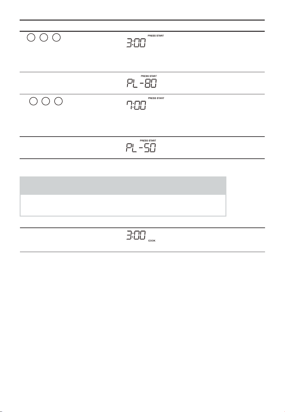
FR-55
Touchez : L’écran affiche :
1.
3 0 0
Pour régler un temps de
cuisson de 3 minutes pour
la première étape.
2.
«Power Level» 3fois
3.
7 0
0
Pour régler une puissance
de cuisson de 7 minutes
pour la deuxième étape.
4.
«Power Level» 6fois
REMARQUE
Vous pouvez programmer une deuxième étape de puissance
«0» pour le temps de repos à l’intérieur du four.
5.
«Start/Enter/+30 Sec»
Compte à rebours

FR-56
Pour régler le niveau de puissance
Il existe onze niveaux de puissance prédéfinis.
L’utilisation de niveaux de puissance plus faibles augmente le temps
de cuisson recommandé pour les aliments tels que fromage, lait et la
cuisson lente et longue des viandes. Consultez un livre de cuisine ou les
recettes pour des recommandations spécifiques.
APPUYER SUR LA TOUCHE
DE NIVEAU DE PUISSANCE
PLUSIEURS FOIS RÉGLER LA
PUISSANCE SOUHAITÉE
POURCENTAGE
APPROXIMATIF DE
PUISSANCE
MOTS COMMUNS POUR LES
NIVEAUX DE PUISSANCE
POWER LEVEL x 1 100% Haut
POWER LEVEL x 2 90%
POWER LEVEL x 3 80%
POWER LEVEL x 4 70% Moyen-élevé
POWER LEVEL x 5 60%
POWER LEVEL x 6 50% Moyen
POWER LEVEL x 7 40%
POWER LEVEL x 8 30% Moyen faible/Dégivrage
POWER LEVEL x 9 20%
POWER LEVEL x 10 10% Bas
POWER LEVEL x 11 0%
Utilisation la grille
La grille permet à plusieurs aliments d’être cuits ou réchauffés à la fois.
Cependant, pour une cuisson et un réchauffage optimaux, utilisez la fonction
Turntable ON et faites cuire avec SENSOR COOKING ou AUTO COOKING sans
la grille. Lorsque la grille est utilisée, réglez le temps et le niveau de puissance
manuellement. Laissez suffisamment d’espace autour et entre les plats.
Faites très attention à l’avancement de la cuisson et du réchauffage.
Repositionnez les aliments et inversez-les de la grille au plateau tournant
et/ou remuez-les au moins une fois pendant tout temps de cuisson ou
de réchauffage. Après la cuisson ou le réchauffage, remuez si possible.
L’utilisation d’un niveau de puissance inférieur contribue à une meilleure
uniformité de cuisson et de réchauffage.
Évitez :
• Rangement de la grille dans le four à micro-ondes lorsqu’elle n’est pas
utilisée.
• Faire éclater du popcorn avec la grille dans le four à micro-ondes.
• Utilisation de tout plat à brunissement sur la grille.
• Utilisation de SENSOR COOKING et AUTO COOKING avec la grille.
• Cuisson directement sur la grille—utilisez des plats allant au four à micro-ondes.

FR-57
REMARQUE
La fonction Démarrer/Arrêter du plateau tournant peut être
utilisée en fonctionnement manuel. Voir page 8 .
Décongélation manuelle
Si les aliments que Si les aliments que vous souhaitez décongeler ne
figurent pas dans le tableau de décongélation ou si leur quantité est
supérieure ou inférieure aux limites indiquées dans la colonne des
quantités du tableau de décongélation (voir pages 7 -7 ), vous devez
procéder à une décongélation manuelle.
Vous pouvez décongeler n'importe quel aliment congelé, qu'il soit cru
ou déjà cuit, en utilisant le niveau de puissance pour 30%.
Pour les aliments congelés crus ou déjà cuits, faites cuire environ
4minutes par livre. Par exemple, décongeler 4 minutes pour 1 livre de
sauce à spaghetti congelée.
Arrêtez toujours le four périodiquement pour retirer ou séparer les
portions décongelées. Si les aliments ne sont pas décongelés à la
fin de la durée de décongélation estimée, programmez le four par
incréments d’une minute au niveau de puissance 30% jusqu’à ce qu’il
soit totalement décongelé.
Lorsque vous utilisez les récipients en plastique du congélateur,
décongelez juste suffisamment pour les retirer du plastique et les
placer dans un plat allant au four à micro-ondes.
CUISSON PAR CAPTEUR
La cuisson par capteur est dotée d’un capteur à commande
électronique qui détecte la vapeur (gouttelettes d’eau et humidité)
émise par les aliments lorsqu’ils chauffent. Le capteur ajuste
automatiquement les temps de cuisson et le niveau de puissance pour
divers aliments et quantités.
Utilisation des paramètres du capteur :
1. Assurez-vous que l’extérieur du l’ustensile et l’intérieur du four sont
secs. Essuyez toute trace d’humidité avec un chiffon sec ou une
serviette en papier.
2. Le four fonctionne avec des aliments à une température de stockage
normale. Par exemple, le popcorn serait à température ambiante.
3. Plus ou moins d’aliments que la quantité indiquée dans le tableau
doit être cuit en suivant les directives de tout livre de cuisine de four
à micro-ondes.
2
2 3

FR-58
4. Pendant la première partie de SENSOR COOKING, le nom de l’aliment
apparaîtra à l’écran. N'ouvrez pas la porte du four et n'appuyez pas
sur le tampon STOP clear pendant cette partie du cycle. La mesure
de la vapeur sera interrompue.
Lorsque le capteur détecte la vapeur émise par les aliments, le reste
du temps de cuisson s’affiche. La porte peut être ouverte lorsque
le temps de cuisson restant apparaît à l’écran. À ce moment, vous
pouvez mélanger ou assaisonner les aliments, comme vous le
souhaitez.
5. Si le capteur ne détecte pas correctement la vapeur lors de la
préparation du popcorn, le four s’éteint et l’heure correcte de la
journée s’affiche. Si le capteur ne détecte pas correctement la vapeur
lors de la cuisson d’autres aliments, UN CODE D’ERREUR apparaît et
le four s’éteint.
6. Vérifiez la température des aliments après la cuisson. Si plus de
temps est nécessaire, continuez la cuisson manuellement.
Couvrir les aliments :
Vous pouvez utiliser ce qui suit pour récupérer vos aliments :
1. Couvercle de cocotte.
2. Enveloppe en plastique : Utilisez une pellicule de plastique
recommandée pour la cuisson au four à micro-ondes. Couvrir le plat
sans serrer ; laisser environ 1/2 pouce à découvert pour permettre
à la vapeur de s’échapper. Le film plastique ne doit pas toucher les
aliments.
3. Papier ciré : Couvrez complètement le plat ; pliez l’excédent
d’enveloppe sous le plat pour le fixer. Si le plat est plus large que le
papier, mettez deux morceaux d’au moins un pouce pour couvrir.
Soyez prudent lorsque vous retirez n'importe quel protection pour
permettre à la vapeur de s’échapper
loin de vous.
REMARQUES SUR LA CUISSON PAR CAPTEUR
1. Le résultat final de la cuisson variera en fonction de l’état des aliments
(par ex. température initiale, forme, qualité). Vérifiez la température des
aliments après la cuisson. Si plus de temps est nécessaire, continuez la
cuisson manuellement.
2. Restez à proximité du four à micro-ondes pendant son utilisation et
vérifiez fréquemment la progression de la cuisson pour éviter que les
aliments ne soient trop cuits.
3. Lorsque SENSOR COOKING est sélectionné, le plateau tournant est
automatiquement réglé pour une cuisson optimale.
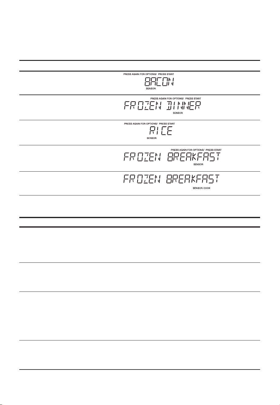
FR-59
Cuisson par Capteur
Vous pouvez cuire des aliments en appuyant plusieurs fois sur le
tampon sensor cook . Vous n’avez pas besoin de calculer le temps de
cuisson ou le niveau de puissance.
• Supposons que vous souhaitez préparer un petit-déjeuner congelé
Touchez : L’écran affiche :
1.
«Sensor Cook»
2.
«Sensor Cook»
3.
«Sensor Cook»
4.
«Sensor Cook»
5.
«Start/Enter/+30 Sec»
Tableau de cuisson par capteur
ALIMENT MONTANT PROCÉDURE
1.Bacon 1-3 tranches Placez les sangles de bacon sur une
grille à bacon micro-ondes pour de
meilleurs résultats. (Utilisez une assiette
avec essuie-tout si le la grille n’est pas
disponible).
2. Dîner surgelé 10 onces/20 onces Placez dans un récipient pour micro-
ondes de taille appropriée. Couvrez d’un
film en plastique. Après la cuisson, remuez
et laissez reposer 3 minutes.
3. Riz 1-2 tasses Placez le riz et le double de liquide
(eau, bouillon de poulet ou de légumes)
dans un plat à micro-ondes de 2 pintes.
Couvrez d’un film en plastique et
ventilé. Après la cuisson, laissez reposer
10minutes. Remuez pour obtenir un riz
plus tendre.
4. Petit-déjeuner
surgelé
8-12 onces. Placez dans un récipient pour micro-
ondes de taille appropriée. Couvrez d’un
film en plastique. Après la cuisson, remuez
et laissez reposer 3 minutes.
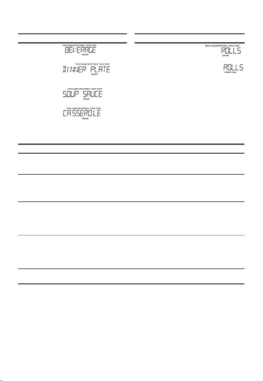
FR-60
Réchauffage par Capteur
• Supposons que vous souhaitiez réchauffer des rouleaux avec un réchauffage par capteur.
Touchez : L’écran affiche : Touchez : L’écran affiche :
1.
Sensor
Reheat
5.
2. 6.
3.
4.
Tableau de réchauffage du capteur
ALIMENT MONTANT PROCÉDURE
Boisson 1 - 3 tasses Pour réchauffer les boissons.
Remuez vivement le liquide avant et après
le chauffage pour éviter l'« éruption ».
Assiettes de diner 1-2 plats Placez dans une assiette peu profonde.
Couvrez d’un film en plastique ventilé.
Laissez reposer 3 minutes après la
cuisson.
Soupe/Sauce 1 tasse Placez dans une casserole peu profonde
allant au four à micro-ondes. Couvrez
d’un film en plastique ventilé. Après la
cuisson, remuez, laissez reposer pendant
3 minutes.
Casserole/Lasagne 10,5 onces Placez dans un bol ou une casserole
allant au four à micro-ondes. Couvrez
d’un film en plastique ventilé. Après la
cuisson, remuez, laissez reposer pendant
3 minutes.
Rouleau/Muffin 1-3 Pièces Placer sur une serviette en papier. Ne pas
couvrir.
«Start/Enter/+30 Sec»
«
»
Sensor
Reheat
«
»
Sensor
Reheat
«
»
Sensor
Reheat
«
»
Sensor
Reheat
«
»
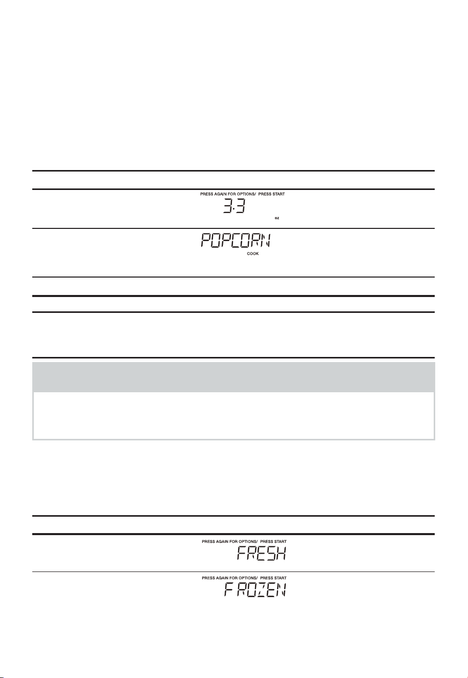
FR-61
CUISSON À UNE TOUCHE
Popcorn
La touche Popcorn du pavé tactile rapide vous permet de faire éclater
des sacs de 3,3, 3 et 1,75 once de popcorn pour micro-ondes emballé
dans le commerce. Faites éclater un seul paquet à la fois. Si vous
utilisez un popcorn popper pour micro-ondes, suivez les instructions du
fabricant.
• Supposons que vous vouliez faire éclater un sac de popcorn de
3,3onces.
Touchez : L’écran affiche :
1.
«Popcorn»
2.
«Start/Enter/+30 Sec»
Compte à rebours
MONTANT Appuyez sur la touche popcorn
3,3 onces. une fois
3,0 onces 2 fois
1,75 once. 3 fois
REMARQUES
1. Retirez la métallique du four à micro-ondes lors de la cuisson du popcorn.
N’utilisez pas de sacs en papier ordinaires. Ne relancez pas les noyaux
non éclatés. Ne faites pas éclater le popcorn dans un ustensile en verre.
Légumes
Il y a 2 options (Légumes surgelés, Légumes frais) sous la rubrique
Légumes.
• Supposons que vous souhaitez cuire deux tasses de légumes
congelés.
Touchez : L’écran affiche :
1.
«Veggies»
2.
«Veggies»
FR-62
3.
«Start/Enter/+30 Sec»
Compte à rebours
Tableau des légumes
ALIMENT
(Température initiale)
MONTANT PROCÉDURE
1. Légumes surgelés
(-18°C)
2 tasses Pas besoin d’ajouter de l’eau. Couvrez
le contenu avec un couvercle ou un film
plastique.
Appuyez deux fois sur la touche
vegetables (légumes) pour les légumes
congelés. Après la cuisson, remuez, laissez
reposer à couvert pendant 3 minutes.
2. Légumes frais
(5 °C)
Brocolis
Choux de Bruxelles
Chou
Chou-fleur (fleurettes)
Chou-fleur (entier)
Épinard
Courge zucchini
2 tasses Lavez et placez dans une casserole.
N’ajoutez pas d’eau si les légumes
viennent d’être lavés. Couvrez avec un
couvercle pour les légumes tendres.
Utilisez un film de plastique pour les
légumes tendres et croquants. Appuyez
une fois sur la touche vegetables
(légumes) pour les légumes frais. Après la
cuisson, remuez, laissez reposer à couvert
pendant 2 à 5 minutes.
Carottes, tranchées
Épis de maïs
Haricots verts
Courge d’hiver
- en dés
- en moitiés
Lavez et placez dans une casserole.
Ajoutez 1 à 4 cuillères à soupe d'eau.
Couvrez avec un couvercle pour les
légumes tendres. Utilisez un film de
plastique pour les légumes tendres et
croquants. Appuyez une fois sur la touche
vegetables (légumes) pour les légumes
frais. Après la cuisson, remuez, laissez
reposer à couvert pendant 2 à 5 minutes.
Menu collation
Le menu Snack sert à faire cuire/réchauffer des aliments qui prennent
peu de temps.
• Supposons que vous souhaitez réchauffer 3 hot-dogs.
Touchez : L’écran affiche :
1.
«Snack Menus»
2.
«Snack Menus»
3.
«Start/Enter/+30 Sec»
FR-63
Touchez : L’écran affiche :
4.
3
5.
«Start/Enter/+30 Sec»
Compte à rebours
Tableau du menu Collations
ALIMENT MONTANT PROCÉDURE
1. Pizza congelée* (6 - 8 onces) À utiliser pour la pizza au four à micro-
ondes congelée. Retirez de l’emballage
et déballez. Suivez les instructions de
l’emballage pour son utilisation et/ou du
plat argenté.
2. Hot-dogs 1 à 6 Pièces Placez le hot-dog dans le pain.
Enveloppez chacun avec une serviette en
papier ou une serviette de table.
3. Repas dans une tasse* 2,39 onces Ce réglage est idéal pour les portions
individuelles d’aliments en conserve
emballées dans un petit récipient pour
micro-ondes, généralement de 6 à 8 onces.
Après la cuisson, remuez les aliments et
laissez reposer 1 à 2 minutes.
4. Repas surgelés pour
enfants*
8,8 onces Utilisez ce tampon pour les aliments
surgelés et les plats préparés. Il ne
donnera pas de résultats satisfaisants
pour la plupart des marques. Vous pouvez
en essayer plusieurs et choisir votre
favori. Retirez l'emballage de l'emballage
extérieur et suivez les instructions
relatives à l'emballage pour le couvrir.
Après la cuisson, laissez reposer à couvert
pendant 1 à 3 minutes.
Pour les menus avec *, veuillez ignorer l'étape 3 et l'étape 4.
Potato
• Supposons que vous souhaitez cuire 1 à 4 pommes de terre au four.
Touchez : L’écran affiche :
1.
«Patato»
2.
«Start/Enter/+30 Sec»
FR-64
REMARQUES
1. Les temps de cuisson sont basés des pommes de terre de 8 onces en
moyenne.
Tableau de pommes de terre au four
ALIMENT MONTANT PROCÉDURE
Potato 1 à 4 portions Percez avec une fourchette à plusieurs
endroits. Placez sur une serviette en
papier sur le plateau tournant. Après la
cuisson, sortez du four et laissez reposer
pendant 5 minutes.
Réglage fonte/ramollissement
Le four utilise une faible puissance pour faire fondre et ramollir les articles. Consultez le
tableau suivant.
• Supposons que vous vouliez faire fondre 2 bâtonnets de beurre.
Touchez : L’écran affiche :
1.
«Melt/Soften»
2.
«Start/Enter/+30 Sec»
3.
2
4.
«Start/Enter/+30 Sec»
Compte à rebours
Table de fusion
CATÉGORIE MONTANT
TOUCHE
NUMÉRIQUE
DIRECTION
FAIRE FONDRE
DU BEURRE
1 ou 2
bâtonnets
1, 2
Déballez et placez dans un ustensile
allant au four à micro-ondes. Pas besoin
de couvrir le beurre. Remuez à la fin de
la cuisson pour terminer la fonte.
FONDRE
CHOCOLAT
2, 4 ou 8
onces.
2, 4, 8
Des pépites de chocolat ou des carrés
de chocolat à cuire peuvent être utilisés.
Déballez les carrés et placez dans un plat
allant au four à micro-ondes. Remuez à la
fin de la cuisson pour terminer la fonte.
FR-65
CATÉGORIE MONTANT
TOUCHE
NUMÉRIQUE
DIRECTION
CRÈME
GLACÉE
RAMOLLIE
Pinte,
1,5Quart.
1, 2
Placez le plat dans le four. La crème glacée
sera suffisamment douce pour faciliter pour
faciliter l’utilisation d’une cuillère à glace.
FROMAGE À
LA CRÈME
RAMOLLI
3 ou 8 onces.
3, 8
Déballez et placez dans un récipient
allant au four à micro-ondes. Le fromage
à la crème sera à température ambiante
et prêt à être utilisé dans la recette.
CUISINE AUTOMATIQUE
Cuisine Automatique
La cuisson automatique est divisée en deux parties : les repas rapides (œufs brouillés,
céréales chaudes, pizzas surgelées, brownies au caramel) et les recettes de dîner
(crevettes à l'ail, pommes de terre rouges à l'asiago, potée de légumes rôtis, risotto au
citron et aux crevettes, chili au poulet blanc).
Touche Aliment MONTANT
Auto Cook x1 Œufs brouillés 1 à 6 œufs
Auto Cook x2 Céréales chaudes 1 à 3 portions
Auto Cook x3 Pizza congelée 12 onces
Auto Cook x4 Brownies au fudge 18 à 19 onces
Auto Cook x5 Crevettes à l’ail Par recette
Auto Cook x6 Champignons farcis Par recette
Auto Cook x7 Pommes de terre rouges Asiago Par recette
Auto Cook x8 Mélange de légumes rôtis Par recette
Auto Cook x9 Risotto aux crevettes et au citron Par recette
Auto Cook x10 Poulet blanc au chili Par recette
Repas rapides
• Supposons que vous souhaitez cuire des céréales chaudes pour 3 portions
Touchez : L’écran affiche :
1.
«Auto Cook»
2.
«Auto Cook»
TABLE DE FUSION
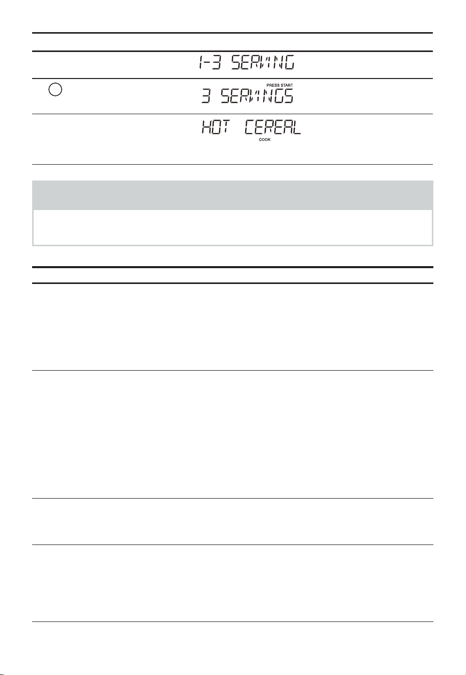
FR-66
Touchez : L’écran affiche :
3.
«Start/Enter/+30 Sec»
4.
3
5.
«Start/Enter/+30 Sec»
Compte à rebours
REMARQUES
Lorsque «AUTO COOKING» est sélectionné, le plateau tournant est
automatiquement réglé pour une cuisson optimale.
Tableau des repas rapides
ALIMENT MONTANT PROCÉDURE
1. Œufs brouillés 1 à 6 œufs Fouettez ensemble l'œuf et le lait (utilisez
1/2 cuillère à soupe de lait pour chaque
œuf) dans un bol allant au micro-ondes
qui a été recouvert d'un vaporisateur de
cuisson. Sélectionnez «Scrambled Eggs»
dans le menu Auto Cook et le nombre
d'œufs à cuire souhaité. Retournez les
aliments à la mi-cuisson.
2. Céréales chaudes 1 à 3 portions Utilisez des paquets individuels ou des
céréales en vrac dans votre variété
préférée: flocons d'avoine, son d'avoine,
crème de blé, farine ou blé. Suivez les
consignes relatives à l'emballage pour la
bonne quantité d'eau ou de lait. Pour éviter
les bouillonnements, il est très important
de choisir un grand récipient car la cuisson
des céréales au micro-ondes provoque une
ébullition élevée. Sélectionnez «Hot Cereal»
dans le menu Auto Cook et le nombre de
portions souhaité.
3. Pizza congelée* 12 onces À utiliser pour la pizza au four à micro-ondes
congelée. Retirez de l’emballage et déballez.
Suivez les instructions de l’emballage pour
son utilisation et/ou du plat argenté.
4. Fudge Brownies 18 à 19 onces Préparez le mélange de brownie selon
les instructions sur l’emballage. Déposez
la pâte à la cuillère dans un plat en verre
allant au four à micro-ondes de
8 x 8 pouces enduit d’un vaporisateur à
cuisson. Sélectionnez «Fudge Brownies»
dans le menu Auto Cook.
Pour les menus avec *, veuillez ignorer l'étape 3 et l'étape 4.
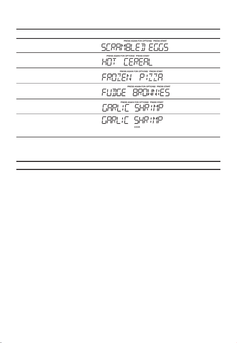
FR-67
Recettes de dîner
• Supposons que vous souhaitiez cuisiner des crevettes à l'ail.
Touchez : L’écran affiche :
1.
«Auto Cook»
2.
«Auto Cook»
3.
«Auto Cook»
4.
«Auto Cook»
5.
«Auto Cook»
6.
«Start/Enter/+30 Sec»
Compte à rebours
Recettes de dîner
Crevettes à l’ail
¼ tasse de beurre
6 gousses d’ail émincées
2 cuillères à soupe de ciboulette fraîche hachée
2 cuillères à soupe de jus de citron
1 cuillère à soupe de pâte de piment
Sel au goût
1 livre de grosses crevettes crus, pelés et déveinés
Mettez le beurre dans une casserole de 2 litres avec couvercle allant au four à micro-
ondes. Faites cuire au four à micro-ondes à puissance élevée pendant 1 minute ou
jusqu’à ce que le beurre fonde. Ajoutez l’ail et faites cuire au four à micro-ondes 1 minute
supplémentaire. Incorporez ciboulette, jus de citron, pâte de piment et sel. Ajoutez les
crevettes en remuant pour bien les enrober. Couvrez et faites cuire au four à micro-
ondes à puissance élevée pendant 5 minutes, ou jusqu’à ce que les crevettes soient
opaques, en remuant après 3 minutes. Servir éventuellement avec du riz cuit chaud.

FR-68
Champignons farcis
1 livre de champignons entiers
2 cuillères à soupe de beurre fondu
1 bouquet d’oignon vert, haché
¼ tasse de parmesan râpé
2 cuillères à soupe de chapelure
1 cuillère à café de jus de citron
¼ cuillère à café de poivre à l'ail
Poivron rouge broyé au goût
Retirez les tiges des champignons et le mettre de côté. Disposer les chapeaux de
champignons sur un plat allant au four à micro-ondes. Hachez finement les tiges de
champignons mis de côté. Mélangez beurre, tiges de champignons hachées et oignon
vert dans un plat allant au four à micro-ondes d’un litre à puissance élevée pendant
2minutes. Ajoutez le reste des ingrédients et bien mélangez. Déposez le rembourage
à la cuillère dans les chapeaux de champignons. Faites cuire au four à micro-ondes à
puissance élevée pendant 4 à 5 minutes ou jusqu’à ce que les champignons deviennent
tendres.
Pommes de terre rouges Asiago
1 ¼ livre de pommes de terre rouges, pelées et tranchées finement
2 cuillères à soupe de farine tout usage
½ cuillère à café de sel
1 ¼ tasse de lait
1 cuillère à soupe de beurre fondu
5 onces de fromage Asiago râpé
Mélangez pommes de terre, farine et sel dans un sac en plastique à fermeture éclair ;
scellez le sac et secouez pour enrober les pommes de terre. Transférez les pommes de
terre dans une casserole légèrement graissée de 2 pintes allant au four à micro-ondes.
Ajoutez le lait et le beurre en bien remuant. Couvrez et faites cuire au four à micro-ondes
à puissance 80% pendant 12 minutes ou jusqu’à ce que les pommes de terre soient
tendres ; saupoudrez de fromage et faites cuire au four à micro-ondes à puissance 80%
pendant une minute supplémentaire ou jusqu’à ce que le fromage fonde.
Mélange de légumes rôtis
1 tasse de mini-carottes
1 tasse de courge jaune tranchée
1 tasse de courgettes tranchées
½ tasse de poivron rouge tranché
½ tasse d’oignon émincé
1 cuillère à soupe de beurre
Ail et herbes pour assaisonnement au goût
Mélangez carottes, courge, courgettes, poivron et oignon dans un plat de 2 litres allant
au four à micro-ondes. Parsemez de beurre et saupoudrez d’assaisonnement. Couvrez
et faites cuire au four à micro-ondes à puissance élevée pendant 8 minutes ou jusqu’au
degré de cuisson souhaité.

FR-69
Risotto au citron et aux crevettes
2 cuillères à soupe de beurre
2 cuillères à soupe d'huile d'olive
2 cuillères à soupe d’échalote finement hachée
4 tasses de bouillon de poulet
¼ tasse de jus de citron fraîchement pressé
2 tasses de risotto
1 livre de crevettes moyennes, pelées et déveinées
1 tasse de petits pois congelés, décongelés
2 cuillères à café de zeste de citron râpé
¼ cuillère à café de poivre noir
¾ cuillère à café de sel
Mélangez beurre, huile d’olive et échalote dans un plat d'un litre, allant au four à micro-
ondes. Faites cuire au four à micro-ondes à puissance élevée pendant 1 minute ou
jusqu’à ce que l’échalote soit tendre. Servez.
Mélangez bouillon de poulet et jus de citron dans une tasse à mesurer ou une
casserole de 2 pintes allant au four à micro-ondes. Couvrez d’un couvercle ou d’une
pellicule plastique ventilée. Faites cuire au four à micro-ondes à puissance maximale
pendant 10minutes. Incorporez le mélange d’échalote et de risotto réservés. Couvrez
et continuez à cuire au four à micro-ondes à puissance 50% pendant 20 minutes.
Incorporez crevettes, pois, zeste de citron râpé, poivre et sel. Couvrez et faites cuire au
four à micro-ondes à puissance 50% pendant 5 minutes, ou jusqu’à ce que les crevettes
soient opaques.
Poulet blanc au chili
1 livre de poitrine de poulet désossée et sans peau, coupée en cubes
½ tasse d’oignon haché
3 gousses d’ail émincées
1 boîte (15 onces) de haricots blancs, égouttés
1 boîte (4 onces) de piment vert haché
1 tasse de bouillon de poulet
1 ½ cuillère à café de poudre de chili
¾ cuillère à café de cumin
½ cuillère à café de sel
½ cuillère à café de poivre noir
½ tasse de coriandre fraîche hachée
2 cuillères à soupe de jus de citron vert frais
Mélangez poulet, oignon et ail dans un plat de 2,5 litres, allant au four à micro-ondes.
Couvrez et faites cuire au four à micro-ondes à puissance élevée pendant 6 minutes, ou
jusqu’à ce que le poulet soit complètement cuit et l’oignon tendre, en remuant après
3minutes.
Ajoutez haricots blancs, piment, bouillon de poulet, poudre de chili, cumin, sel et poivre,
en bien remuant. Couvrez et faites cuire au four à micro-ondes à puissance élevée
pendant 10 minutes, en remuant après 5 minutes.
Incorporez coriandre et jus de lime avant de servir.
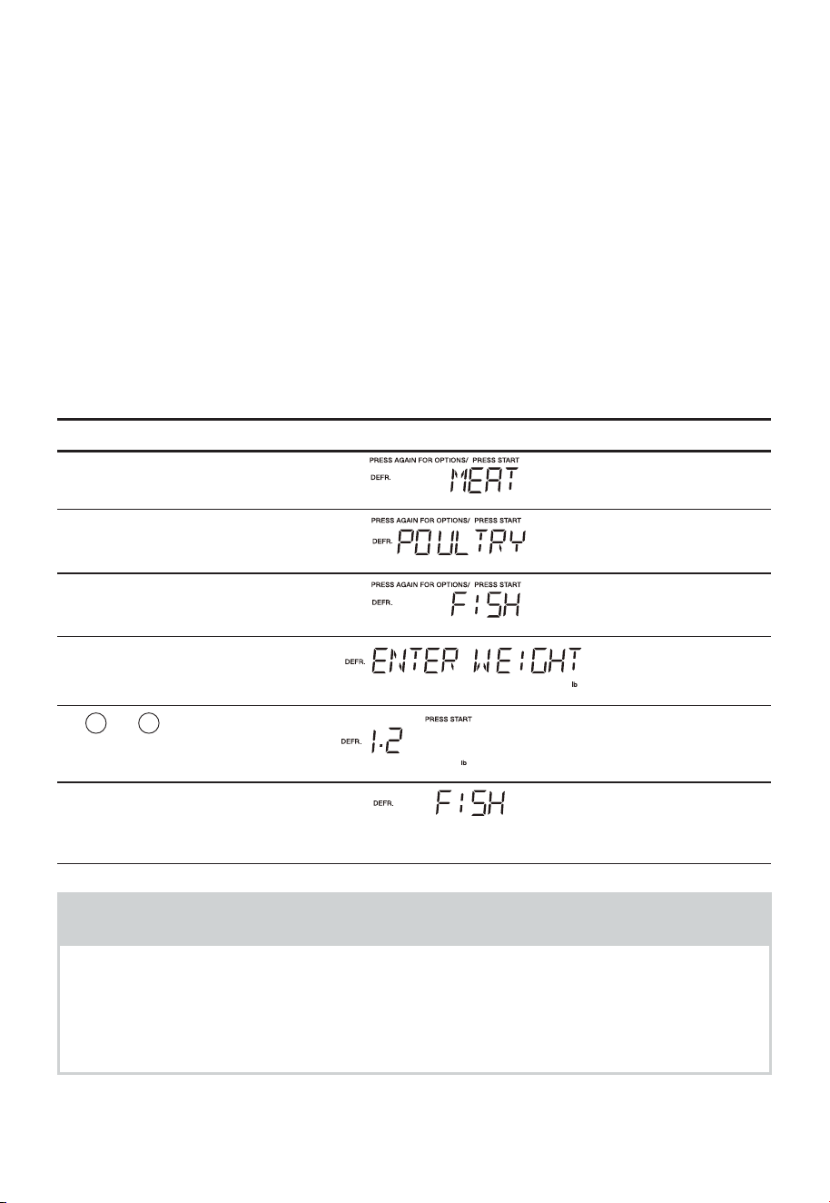
FR-70
DÉCONGÉLATION AUTOMATIQUE
Utilisation de la décongélation automatique
La fonction de décongélation automatique vous offre la meilleure méthode de
décongélation pour les aliments surgelés. Le guide de cuisson vous montre quelle
séquence de décongélation est recommandée pour les aliments que vous décongelez.
Pour plus de commodité, la décongélation automatique comprend un mécanisme de
bip intégré qui vous rappelle de vérifier, retourner, séparer ou réorganiser les aliments
afin d’obtenir les meilleurs résultats de décongélation. Trois niveaux de décongélation
différents sont fournis :
1. VIANDE
2. VOLAILLE
3. POISSON
Le poids disponible est de 0,1 à 6,0 lb
• Supposons que vous vouliez décongeler 1,2 lb de poisson.
Touchez : L’écran affiche :
1.
«Auto Defrost»
2.
«Auto Defrost»
3.
«Auto Defrost»
4.
«Start/Enter/+30 Sec»
5.
1
et
2
Pour entrer le poids
6.
«Start/Enter/+30 Sec»
COOK
Compte à rebours
REMARQUES
Le four émettra un bip pendant le cycle de «DEFROST». À ce stade,
ouvrez la porte et tournez, séparez ou réorganisez les aliments. Retirez
toutes les portions décongelées. Remettez les portions congelées dans
le four et appuyez sur «Start/Enter/+30 Sec» pour reprendre le cycle de
décongélation.
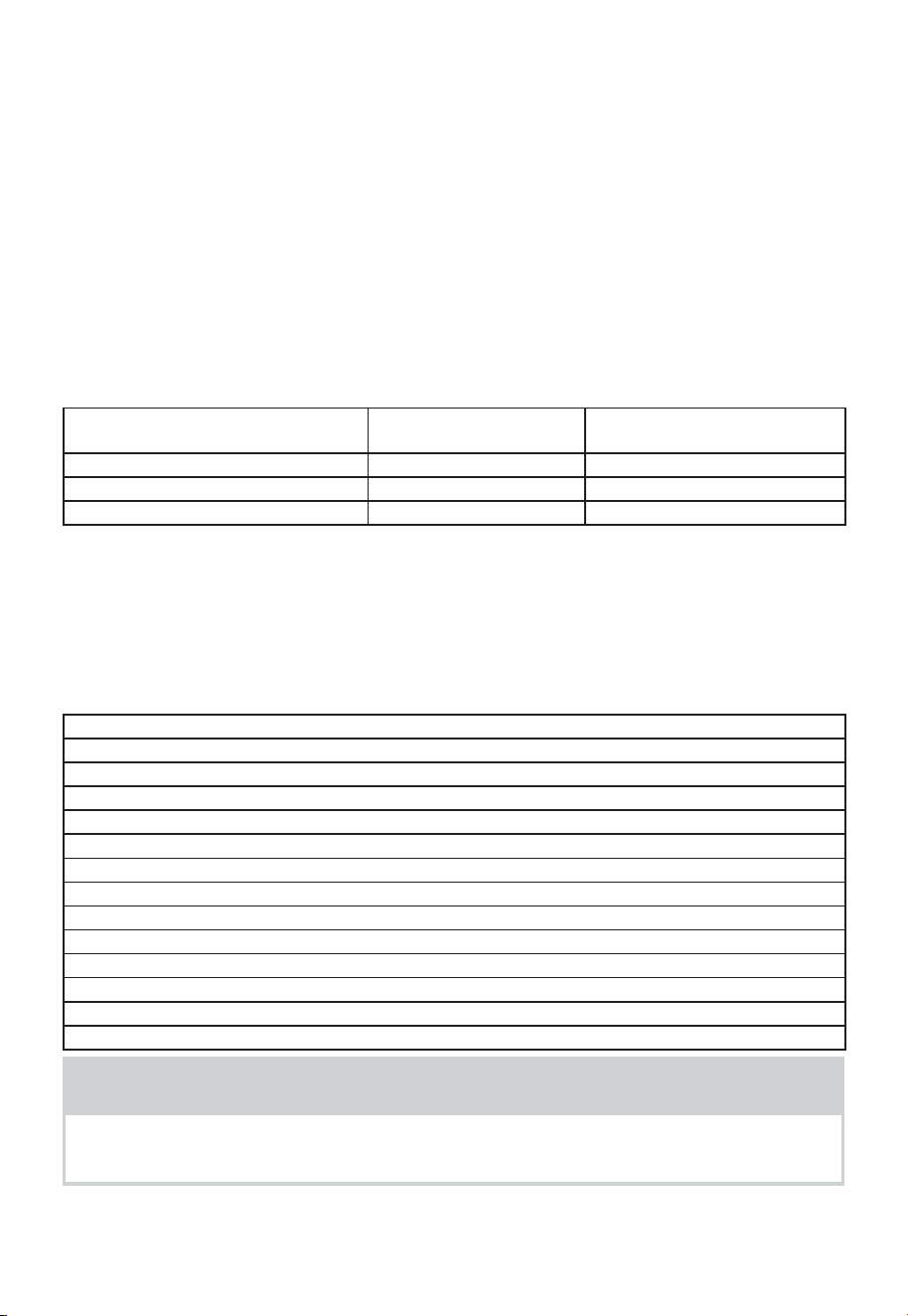
FR-71
Conseils d’utilisation
• Pour de meilleurs résultats, retirez le poisson, les crustacés, la viande et la volaille de son
enveloppe d’origine en papier ou en plastique fermé (enveloppe). Autrement, l’enveloppe
retient la vapeur et le jus près des aliments, provoquant la cuisson uniquement de la
surface extérieure des aliments.
• Pour de meilleurs résultats, roulez votre viande hachée en boule avant de la congeler.
Pendant le cycle DÉCONGÉLATION, le four à micro-ondes signale quand il est temps
de retourner la viande. Grattez tout excès de givre de la viande et poursuivez la
décongélation.
• Placez les aliments dans un récipient peu profond ou sur une grille à rôtir pour micro-
ondes pour récupérer les égouttements.
Ce tableau montre les sélections de types d’aliments et les poids que vous pouvez
définir pour chaque type. Pour de meilleurs résultats, desserrez ou retirez l’enveloppe
sur les aliments.
APPUYER SUR LA TOUCHE Catégorie POIDS QUE VOUS POUVEZ
FIXER (dixièmes de livre)
Auto Defrost x 1 Viande 0,1 à 6,0 livres
Auto Defrost x 2 Volaille 0,1 à 6,0 livres
Auto Defrost x 3 Poisson 0,1 à 6,0 livres
Tableau de conversion de poids
Vous êtes probablement habitué à mesurer les aliments en livres et en onces qui sont des
fractions du livre (par exemple, 4 onces équivalent à 1/4 de livre). Cependant, pour entrer
le poids des aliments dans la décongélation automatique, vous devez spécifier les livres
et les dixièmes de livre. Si le poids sur l’emballage alimentaire est en fractions de livre,
vous pouvez utiliser le tableau suivant pour convertir le poids en décimales.
Poids équivalent
ONCES POIDS DÉCIMAL
1,6 0,10
3,2 0,20
4,0 0,25 Un quart de livre
4,8 0,30
6,4 0,40
8,0 0,50 une demi-livre
9,6 0,60
11,2 0,70
12,0 0,75 trois quarts de livre
12,8 0,80
14,4 0,90
16,0 1,0 une livre
REMARQUES
Si le poids est compris entre deux décimales, arrondissez au poids inférieur
pour obtenir les meilleurs résultats de décongélation.
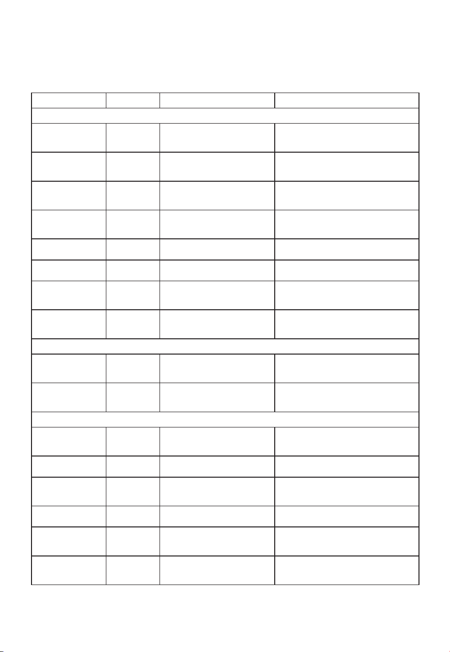
FR-72
Tableau de décongélation automatique
REMARQUE:
Les gros morceaux de viande gras ou de forme irrégulière doivent
avoir les zones étroites ou grasses protégées au début de la séquence de
décongélation.
Paramètres de viande
ALIMENT RÉGLAGE AU BIP INSTRUCTIONS PARTICULIÈRES
BŒUF
Bœuf haché, en vrac VIANDE Retirez les portions décongelées
à la fourchette. Retourner.
Remettez le reste au four.
Ne décongelez pas moins de 1/4 lb.
Congelez en forme de boule.
Bœuf haché, en
galettes
VIANDE Séparez et réorganisez. Ne décongelez pas moins de 2 onces de
galettes.
Appuyez au milieu lors de la congélation.
Steak rond VIANDE Retourner. Couvrez les zones
chaudes avec du papier
d’aluminium.
Placez dans un plat allant au four à micro-
ondes.
Steak de filet VIANDE Retourner. Couvrez les zones
chaudes avec du papier
d’aluminium.
Placez dans un plat allant au four à micro-
ondes.
Ragoût de bœuf VIANDE Retirez les portions décongelées
à la fourchette. Reste séparé.
Placez dans un plat allant au four à micro-
ondes.
Rôti en pot, rôti de
mandrin
VIANDE Remettez le reste au four. Placez dans un plat allant au four à micro-
ondes.
Rôti de côtes VIANDE Retourner. Couvrez les zones
chaudes avec du papier
d’aluminium.
Placez dans un plat allant au four à micro-
ondes.
Rôti de croupe roulé VIANDE Retourner. Couvrez les zones
chaudes avec du papier
d’aluminium.
Placez dans un plat allant au four à micro-
ondes.
AGNEAU
Cubes pour ragoût VIANDE Retourner. Couvrez les zones
chaudes avec du papier
d’aluminium.
Placez dans un plat allant au four à micro-
ondes.
Côtelettes
(1 pouce d’épaisseur)
VIANDE Retirez les portions décongelées
à la fourchette. Remettez le reste
au four.
Placez dans un plat allant au four à micro-
ondes.
PORC
Côtelettes
(1/2 pouce
d’épaisseur)
VIANDE Séparez et réorganisez. Placez dans un plat allant au four à micro-
ondes.
Hot-dogs VIANDE Séparez et réorganisez. Placez dans un plat allant au four à micro-
ondes.
Travers de porc à la
paysanne
VIANDE Retourner. Couvrez les zones
chaudes avec du papier
d’aluminium.
Placez dans un plat allant au four à micro-
ondes.
Saucisses, Liens VIANDE Séparez et réorganisez. Placez dans un plat allant au four à micro-
ondes.
Saucisse, en vrac VIANDE Retirez les portions décongelées
à la fourchette. Retourner.
Remettez le reste au four.
Placez dans un plat allant au four à micro-
ondes.
Rôti de longe,
désossé
VIANDE Retourner. Couvrez les zones
chaudes avec du papier
d’aluminium.
Placez dans un plat allant au four à micro-
ondes.
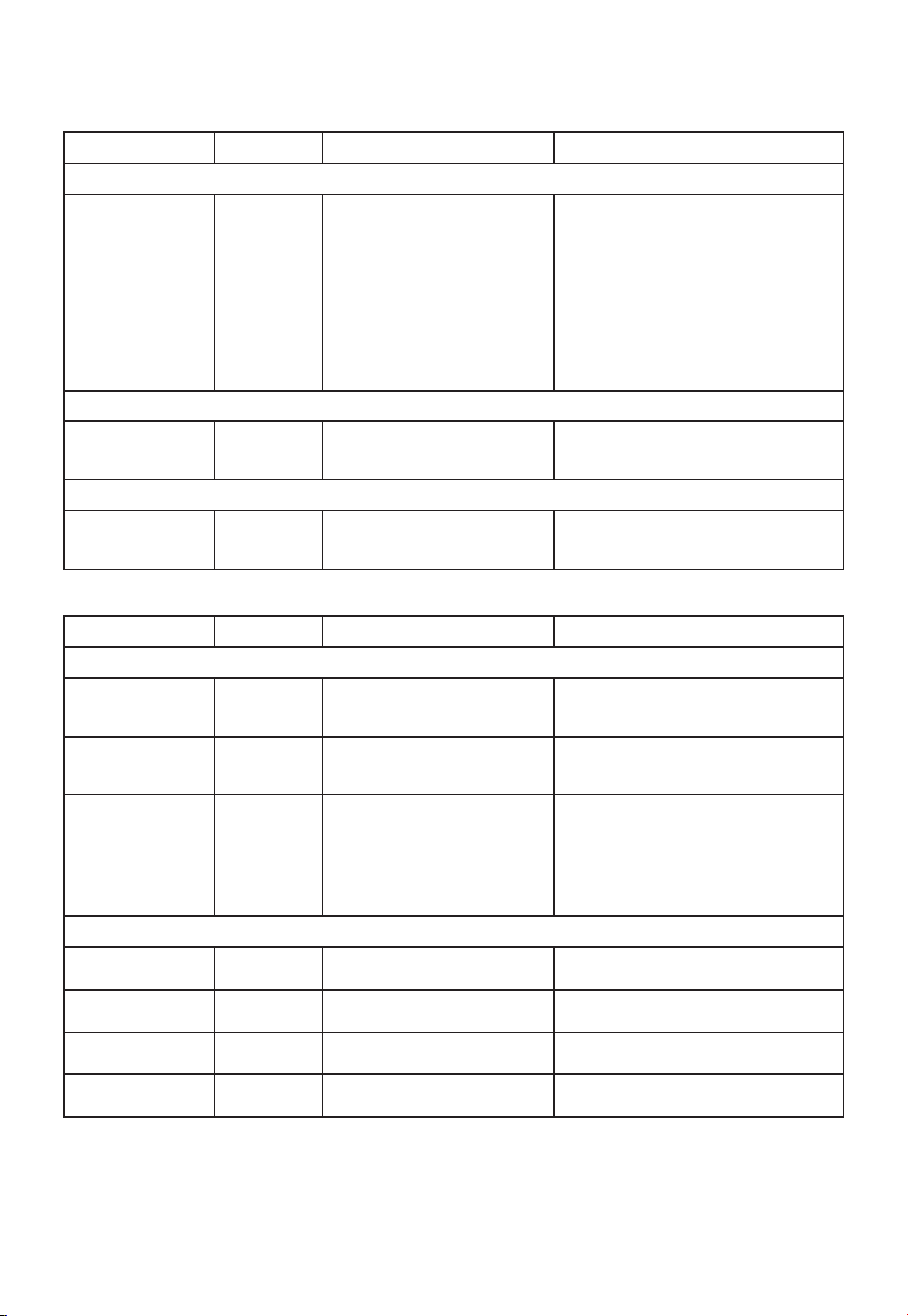
FR-73
Tableau de décongélation automatique (suite)
Paramètres de volaille
ALIMENT RÉGLAGE AU BIP INSTRUCTIONS PARTICULIÈRES
POULET
Entier
(Jusqu’à 6 livres)
VOLAILLE Retournez le côté poitrine vers le
bas.
Couvrez les zones chaudes avec
du papier d’aluminium.
Placez le poulet côté poitrine vers le haut
dans un plat allant au four à micro-ondes.
Terminez la décongélation en plongeant
dans l’eau froide. Retirez les abats lorsque
le poulet est partiellement décongelé.
Découpe Séparez les pièces et réorganisez.
Retourner. Couvrez les zones
chaudes avec du papier
d’aluminium.
Placez dans un plat allant au four à micro-
ondes.
Terminez la décongélation en plongeant
dans l’eau froide.
CORNOUAILLAIS
POULES
Entier
VOLAILLE Retourner. Couvrez les zones
chaudes avec du papier
d’aluminium.
Placez dans un plat allant au four à micro-
ondes. Terminez la décongélation en
plongeant dans l’eau froide.
DINDE
Poitrine
(Jusqu’à 6 livres)
VOLAILLE Retourner. Couvrez les zones
chaudes avec du papier
d’aluminium.
Placez dans un plat allant au four à micro-
ondes. Terminez la décongélation en
plongeant dans l’eau froide.
Paramètres de poisson
ALIMENT RÉGLAGE AU BIP INSTRUCTIONS PARTICULIÈRES
POISSON
Filets POISSON Retourner. Séparez les filets
lorsqu’ils sont partiellement
décongelés, si possible.
Placez dans un plat allant au four à micro-
ondes. Séparez soigneusement les filets
sous l’eau froide.
Steaks POISSON Séparez et réorganisez. Placez dans un plat allant au four à micro-
ondes. Faites couler de l’eau froide pour
terminer la décongélation.
Entier POISSON Retourner Placez dans un plat allant au four à
micro-ondes. Couvrez la tête et la queue
avec du papier d’aluminium ; ne laissez
pas le papier d’aluminium toucher les
parois du four à micro-ondes. Terminez
la décongélation en plongeant dans l’eau
froide.
FRUITS DE MER
Chair de crabe POISSON Briser. Retourner. Placez dans un plat allant au four à micro-
ondes.
Queues de homard POISSON Briser. Retourner. Placez dans un plat allant au four à micro-
ondes.
Crevettes POISSON Briser. Retourner. Placez dans un plat allant au four à micro-
ondes.
Escalopes POISSON Briser. Retourner. Placez dans un plat allant au four à micro-
ondes.

FR-74
Conseils de décongélation
• Lors de l’utilisation de Auto Defrost, le poids à saisir est le poids net en livres et en
dixièmes de livres (le poids de l’aliment moins celui du récipient).
• Avant de décongeler, retirez toutes les attaches métalliques qui viennent souvent avec
les sacs d’aliments congelés et remplacez-les par des ficelles ou des bandes élastiques.
• Ouvrez les récipients, comme les cartons, avant de les placer dans le four.
• Fendez ou percez toujours les sachets ou les emballages en plastique.
• Si les aliments sont emballés dans du papier d’aluminium, retirez-les du papier et
placez-les dans un récipient approprié.
• Coupez la peau des aliments non dépouillés, comme les saucisses.
• Pliez les sachets en plastique des aliments pour assurer une décongélation uniforme.
• Sous-estimez toujours le temps de décongélation. Si les aliments sont encore congelés
à l’intérieur, les remettre dans le four à micro-ondes pour plus de décongélation.
• La durée de décongélation varie en fonction de la solidité de congélation des aliments.
• La forme de l’emballage détermine la vitesse de décongélation des aliments. Les
emballages peu profonds décongèlent plus rapidement que ceux profonds.
• Lorsque les aliments commencent à décongeler, séparez les morceaux pour qu'ils se
transforment plus facilement et plus rapidement.
• • Utilisez de petits morceaux de papier d’aluminium pour protéger les parties des
aliments tels que ailes de poulet, bouts de cuisses, queues de poisson, ou zones qui
commencent à chauffer. Assurez-vous que le papier d’aluminium ne touche pas les
côtés, le haut ou le bas du four. Le papier d’aluminium peut endommager la doublure
du four.
• Pour de meilleurs résultats, laissez les aliments reposer après la décongélation.
• Retournez les aliments pendant la décongélation ou le temps de repos.
• Cassez et retirez les aliments si nécessaire.
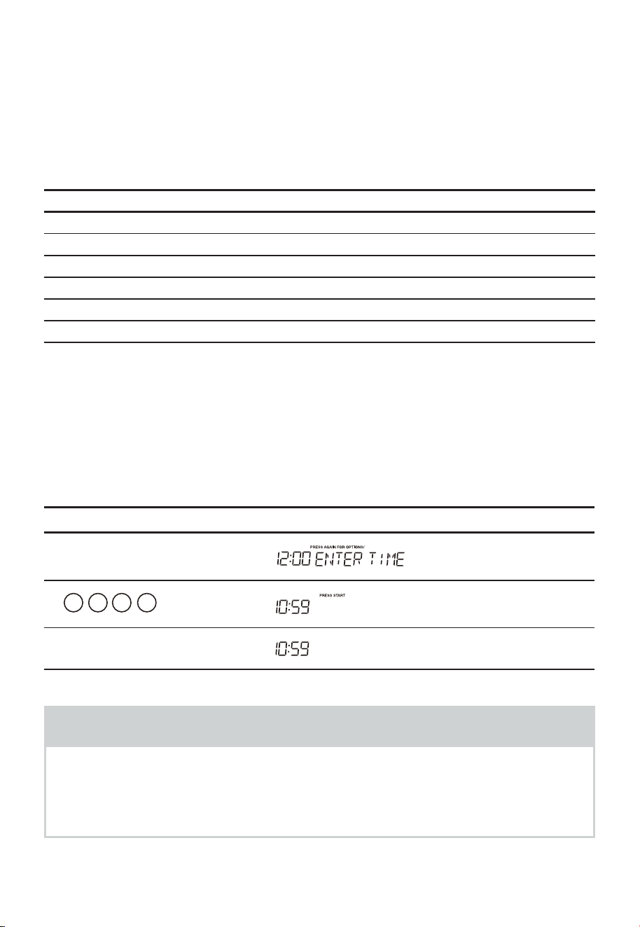
FR-75
FONCTIONS PRATIQUES
1. Préférences utilisateur
Le four à micro-ondes offre des réglages qui vous permettent de personnaliser le
fonctionnement à votre convenance. Vous trouverez ci-dessous un tableau indiquant
les différents réglages. Appuyez plusieurs fois sur la touche User pref (Préférences
utilisateur) pour aller jusqu’à la fonction de réglage souhaitée.
Appuyer sur la touche Option
User pref X 1 Horloge
User pref X 2 Verrouillage des commandes
User pref X 3 Volume (Désactivé/Faible/Moyen/Élevé)
User pref X 4 Poids (livre/kg)
User pref X 5 Écran de l’horloge
User pref X 6 Démo
(1). Réglage de l’heure
L’horloge peut être désactivée lorsque le four à micro-ondes est branché pour la
première fois et
la touche «Stop/Clear» est sélectionnée.
Pour réactiver l’horloge, suivez les instructions données par l’horloge.
• Supposons que vous souhaitez régler l’horloge sur 10:59.
Touchez : L’écran affiche :
1.
«User pref»
2.
1 0 5 9
3.
«Start/Enter/+30 Sec»
REMARQUES
1. Vous ne pouvez pas entrer une heure incorrecte (ex. 2:89), le 8 est un chiffre non
valide et ne peut pas être entré.
Entez l’heure correcte.
2. Si vous touchez «Stop/Clear» pendant le réglage de l’heure, l’écran affiche la
dernière heure du jour réglée ou un affichage vide si aucune heure n’a été réglée.
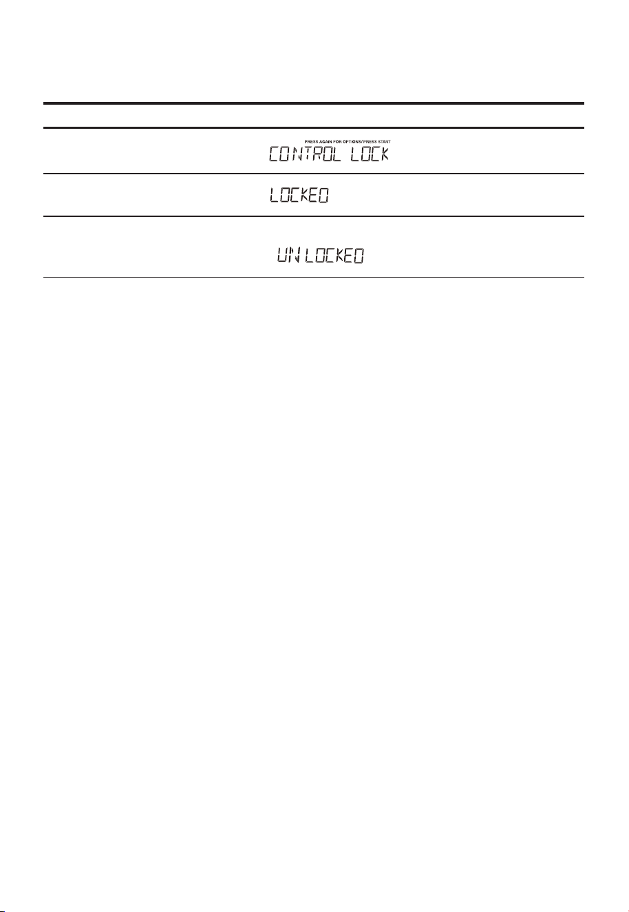
FR-76
(2). Activer/désactiver le verrouillage des commandes
Pour activer le verrouillage des commandes.
Touchez : L’écran affiche :
1.
«User Pref» X 2
2.
«Start/Enter/+30 Sec»
Pour mettre le verrouillage des commandes sur OFF, touchez User pref puis
touchez « Start/Enter/+30 Sec »
s'affichera.
,
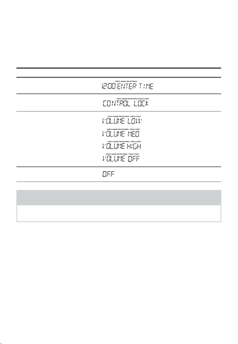
FR-77
(3). Réglage du son à un niveau Faible/Moyen/Élevé/Désactivé
Des signaux sonores sont disponibles pour vous guider lors du réglage et de l’utilisation
de votre four.
• Un son de programmation retentira chaque fois que vous appuierez sur un bouton.
• Trois sons signalent la fin d'un compte à rebours du Kitchen Timer.
• Trois sons signalent la fin d'un cycle de cuisson.
• Supposons que vous souhaitez désactiver le signal sonore.
Touchez : L’écran affiche :
1.
«User Pref»
2.
«User Pref»
3.
«User Pref»
4.
«Start/Enter/+30 Sec»
REMARQUES
Lorsque le cycle de cuisson est terminé, END apparaît et un signal sonore est émis si
le son est activé.
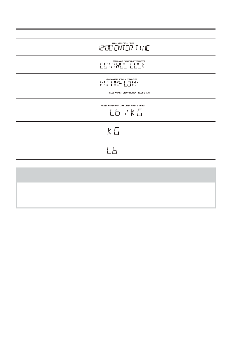
FR-78
(4). Réglage du poids Lb/KG
• Supposons que vous souhaitiez basculer le poids entre livre et kilogramme.
Touchez : L’écran affiche :
1.
«User Pref»
2.
«User Pref»
3.
«User Pref»
4.
«User Pref»
5
. «Start/Enter/+30 Sec»
kg
Ib
ou
REMARQUES
Si l’écran affiche kg, appuyez sur la touche «Start/Enter/+30 Sec» pour réinitialiser
les commandes du four à livres. Pour revenir à kg, il faut appuyer quatre fois sur
« User Pref » puis sur « Start/Enter/+30 Sec ».

FR-79
(5). Réglage de l’affichage de l’heure
• Supposons que vous souhaitez régler l'affichage de l'horloge.
Touchez : L’écran affiche :
1.
«User Pref»
2.
«User Pref»
3.
«User Pref»
4.
«User Pref»
5
. «User Pref»
ou
6.
«Start/Enter/+30 Sec»
ou
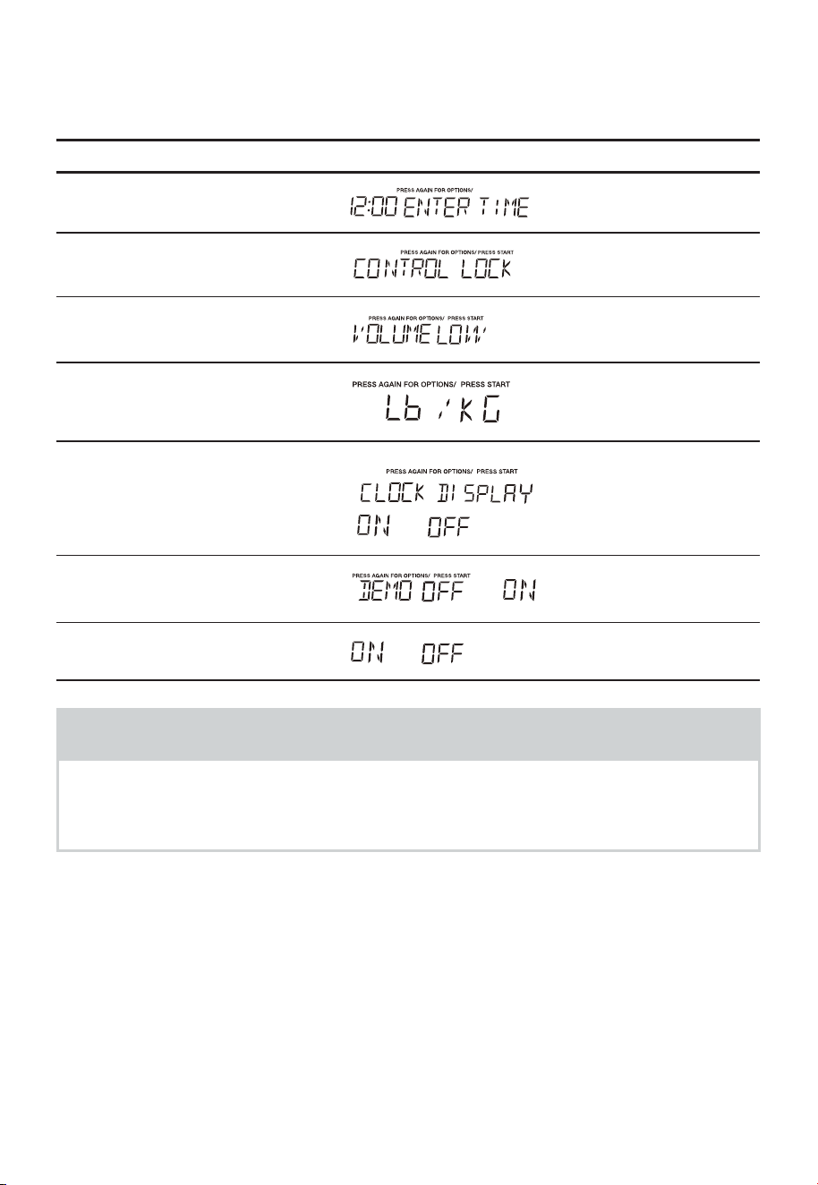
FR-80
(6). Activer/désactiver le mode démo
• Supposons que vous souhaitez accéder au mode Demo. Lorsque le mode Démo est
activé, les fonctions de programmation fonctionnent en mode compte à rebours rapide
sans puissance de cuisson.
Touchez : L’écran affiche :
1.
«User Pref»
2.
«User Pref»
3.
«User Pref»
4.
«User Pref»
5
. «User Pref»
6.
«User Pref»
ou
7.
«Start/Enter/+30 Sec»
ou
REMARQUES
Lorsque «Start/Enter/+30 Sec» est appuyé et que le réglage précédent était OFF, il
s’allume. Si vous souhaitez mettre sur OFF le mode demo, vous devez appuyer six fois
sur User pref, puis appuyer sur «Start/Enter/+30 Sec».
ou
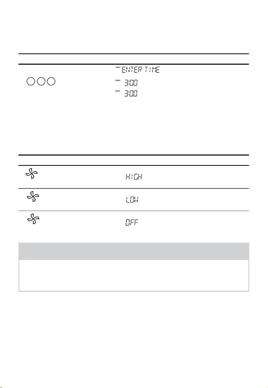
FR-81
2. Réglage du minuteur
Vous pouvez utiliser votre four à micro-ondes à l’aide d’un minuteur. Vous pouvez définir
jusqu’à 99 minutes, 99 secondes.
Le minuteur de cuisine peut être utilisé pendant que le four à micro-ondes est en marche.
• Pour régler Le minuteur sur trois minutes.
Touchez : L’écran affiche :
1.
«Timer»
2.
03 0
3.
«Timer»
Le minuteur commence le compte à rebours
3. Utilisation du ventilateur
La touche Vent contrôle le ventilateur, qui offre 2 vitesses. Si le ventilateur est off, la
première pression sur le bouton règle le ventilateur sur High, la deuxième pression sur
LOW et la troisième sur OFF.
Touchez : L’écran affiche :
1.
2.
3.
REMARQUES
Si la température du four ou du plateau tournant devient trop élevée, le ventilateur se
met automatiquement en marche pour les protéger.
Il peut rester en marche jusqu’à une heure pour refroidir le four.
Lorsque cela se produit, la touche Vent n’éteint pas le ventilateur.
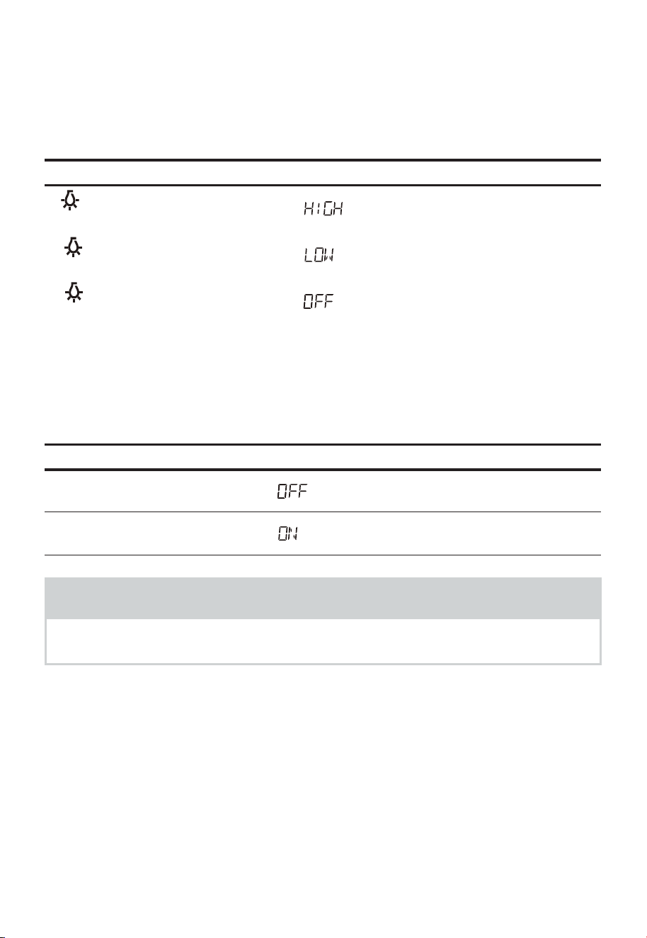
FR-82
4. Utilisation de la lumière de cuisson
La touche d’icône de lumière contrôle la lumière de cuisson. Si la lumière est OFF,
la première pression sur le bouton de la lumière mettra la lumière sur ON (high), la
deuxième pression réduira la puissance de la lumière à Low et la troisième pression la
mettra sur OFF.
Touchez : L’écran affiche :
1.
2.
3.
5. Démarrage/Arrêt du plateau tournant
Appuyez sur Turntable On-Off pour Démarrer/Arrêter du plateau tournant.
Pour de meilleurs résultats de cuisson, laissez le plateau tournant en marche. Il peut être
arrêté pour les grands plats.
Touchez : L’écran affiche :
1. «Turntable On-Off»
2.
«Turntable On-Off»
REMARQUES
Parfois, le plateau tournant peut devenir chaud au toucher pendant et après la
cuisson. N’utilisez pas le four à vide.

FR-83
DÉPANNAGE
Recherchez votre problème dans le tableau ci-dessous et essayez les solutions proposées
pour le résoudre. Si le four à micro-ondes ne fonctionne toujours pas correctement,
contactez le centre de service agréé le plus proche.
PROBLÈME CAUSES POSSIBLES SOLUTIONS POSSIBLES
Le four ne démarre pas
• Le cordon électrique du four
n'est pas branché.
• La porte est ouverte.
• Mauvaise opération choisie.
• Branchez l'appareil à une
prise électrique.
• Fermez la porte et réessayez.
• Consultez le guide
d'utilisation.
Arc ou étincelle
• Vous avez introduit des
matériaux qu'il faut éviter
d'utiliser dans un four à micro-
ondes.
• Le four est utilisé à vide.
• La cavité contient de la
nourriture renversée.
• Utilisez uniquement des plats
allant au four à micro-ondes.
• N'utilisez pas le four à vide.
• Nettoyez la cavité avec une
serviette humide.
Aliments mal cuits
• Vous avez introduit des
matériaux qu'il faut éviter
d'utiliser dans un four à micro-
ondes.
• Les aliments ne sont pas
entièrement décongelés.
• Temps de cuisson ou niveau
de puissance inapproprié.
• Les aliments ne sont ni
retournés ni remués.
• Utilisez uniquement des plats
allant au four à micro-ondes.
• Décongelez entièrement les
aliments.
• Utilisez un temps de cuisson
ou un niveau de puissance
approprié.
• Retournez ou remuez les
aliments.
Aliments trop cuits
• Temps de cuisson ou niveau
de puissance inapproprié.
• Utilisez un temps de cuisson
ou un niveau de puissance
approprié.
Aliments insuffisamment
cuits
• Vous avez introduit des
matériaux qu'il faut éviter
d'utiliser dans un four à micro-
ondes.
• Les aliments ne sont pas
entièrement décongelés.
• Les orifices de ventilation du
four sont obstrués.
• Temps de cuisson ou niveau
de puissance inapproprié.
• Utilisez uniquement des plats
allant au four à micro-ondes.
• Décongelez entièrement les
aliments.
• Vérifiez que les orifices de
ventilation du four ne sont
pas obstrués.
• Utilisez un temps de cuisson
ou un niveau de puissance
approprié.
Décongélation
incorrecte
• Vous avez introduit des
matériaux qu'il faut éviter
d'utiliser dans un four à micro-
ondes.
• Temps de cuisson ou niveau
de puissance inapproprié.
• Les aliments ne sont ni
retournés ni remués.
• Utilisez uniquement des plats
allant au four à micro-ondes.
• Utilisez un temps de cuisson
ou un niveau de puissance
approprié.
• Retournez ou remuez les
aliments.

FR-84
MARQUES COMMERCIALES,
DROITS D'AUTEUR ET MENTIONS
LÉGALES
Le logo, les marques verbales, le nom commercial, l'habillage commercial et
toutes les versions de ces éléments sont des propriétés précieuses de Midea Group ou
de ses sociétés affiliées (« Midea »), auxquelles sont rattachés des marques, des droits
d'auteur et d'autres droits de propriété intellectuelle, ainsi que toute bonne volonté
résultant de l'utilisation d'une partie quelconque de la marque Midea. L'utilisation de la
marque Midea à des fins commerciales sans le consentement écrit préalable de Midea
peut constituer une violation de la marque ou une concurrence déloyale en violation des
lois pertinentes.
Ce manuel est créé par Midea et l'entreprise se réserve tous les droits d'auteur. Aucune
entité ou personne ne peut utiliser, dupliquer, modifier, distribuer en totalité ou en partie
ce manuel, ni le regrouper ou le vendre avec d'autres produits sans le consentement écrit
préalable de Midea.
Toutes les fonctions et instructions décrites étaient à jour au moment de l'impression de
ce manuel. Toutefois, le produit réel peut varier en raison des fonctions et de conceptions
améliorées.

FR-85
AVIS SUR LA PROTECTION DES
DONNÉES
Pour la fourniture des services convenus avec le client,
Nous nous engageons à respecter sans restriction toutes les dispositions de la loi
applicable en matière de protection des données, conformément aux pays dans desquels
les services au client seront fournis.
De manière générale, nous traitons les données dans le but de remplir notre obligation
contractuelle avec vous et pour des raisons de sécurité des produits, pour sauvegarder
vos droits en rapport avec les questions de garantie et d'enregistrement des produits.
Dans certains cas, mais uniquement si une protection appropriée des données est
assurée, les données personnelles peuvent être transférées à des destinataires situés en
dehors de l'Espace économique européen.
De plus amples informations sont fournies sur demande. Vous pouvez contacter notre
délégué à la protection des données à l’adresse suivante [email protected]om. Pour
exercer vos droits, notamment celui de vous opposer à ce que vos données personnelles
soient traitées à des fins de marketing direct, veuillez nous contacter via
[email protected]om. Pour plus d'informations, il faut suivre le QR Code.


www.midea.com
©Midea 2022. Tous droits réservés.
