MICROWAVE OVEN
USER MANUAL
Warning notices: Before using this product, please read this manual carefully and keep it for future reference.
The design and specifications are subject to change without prior notice for product improvement. Consult
with your dealer or manufacturer for details.
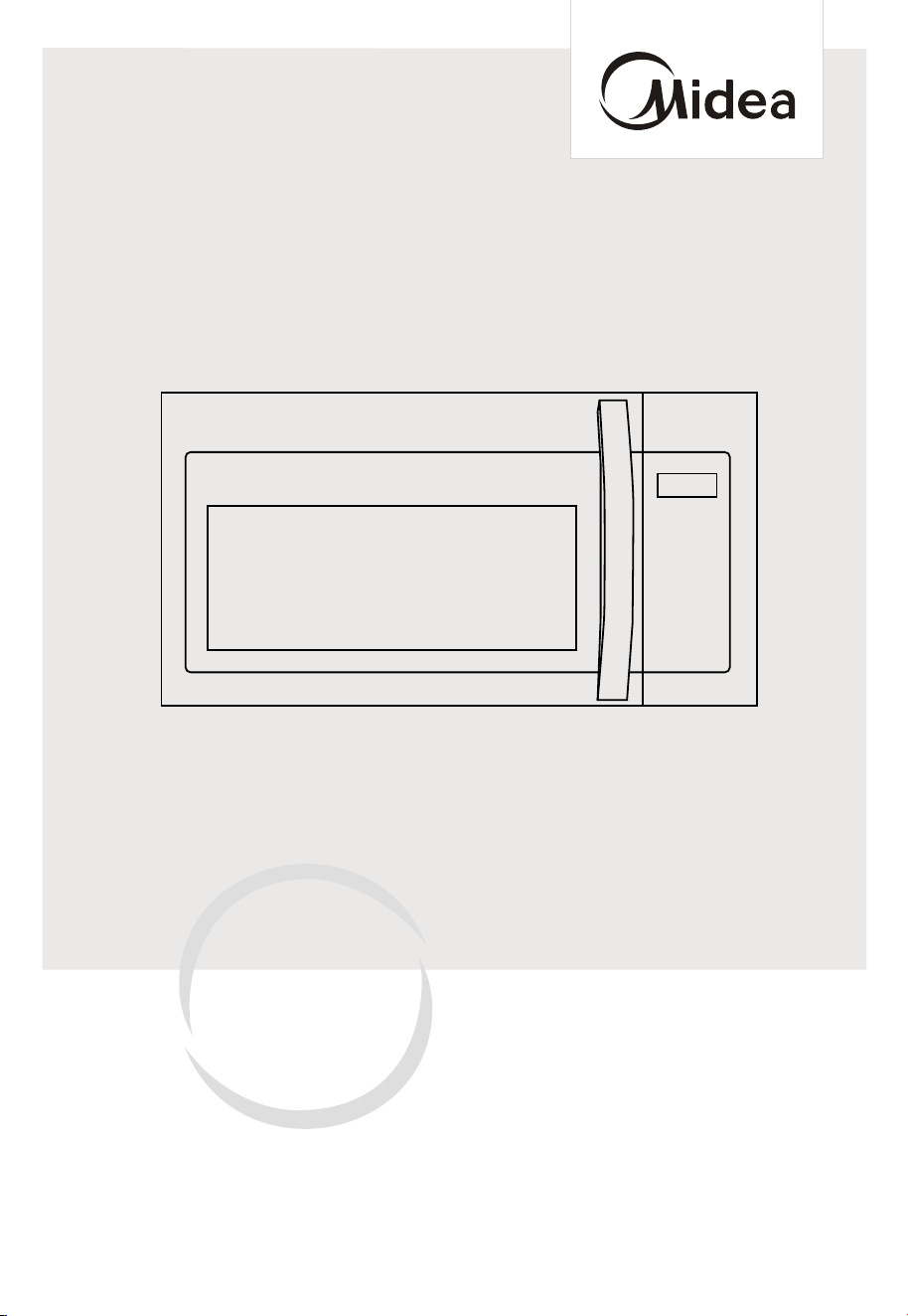
The diagram above is just for reference. Please take the appearance of the actual product as the standard.
MMO17S12ASTC
Fre
e 3 months
extension of the
original limited warranty
period!* Simply text a
picture of your proof of
purchase to:
1-844-224-1614
*The warranty extension is for the three months
immediately following
the completion of the product’s original warranty
period. Individuals do not need to register the
product in order to get all the rights and remedies
of registered owners under the original limited
warranty.

THANK YOU LETTER
Thank you for choosing Midea! Before using your new Midea product, please read
this manual thoroughly to ensure that you know how to operate the features and
CONTENTS
functions that your new appliance offers in a safe way.
THANK YOU LETTER
THANK YOU LETTER
--------------------------------------------------
SAFETY INSTRUCTIONS
----------------------------------------------
SPECIFICATION
---------------------------------------------------------
PRODUCT OVERVIEW
-------------------------------------------------
PRODUCT INSTALLATION
-------------------------------------------
OPERATION INSTRUCTIONS
----------------------------------------
TROUBLESHOOTING
--------------------------------------------------
TRADEMARKS, COPYRIGHTS AND LEGAL STATEMENT
---
DATA PROTECTION NOTICE
-------------------------------------- --
EN-01
EN-01
EN-02
EN-11
EN-12
EN-
EN-51
EN-61
EN-62
EN-63
13
EN-64
YEAR LIMITED WARRANTY
--
---------------------------------
1
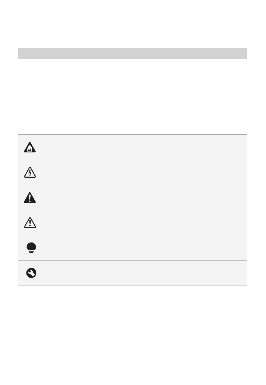
Danger
This symbol indicates that there are dangers to the life and health of
persons due to extremely flammable gas.
Warning of electrical voltage
This symbol indicates that there is a danger to life and health of
persons due to voltage.
Warning
The signal word indicates a hazard with a medium level of risk which, if
not avoided, may result in death or serious injury.
Caution
The signal word indicates a hazard with a low degree of risk which, if
not avoided, may result in minor or moderate injury.
Attention
The signal word indicates important information (e.g. damage to
property), but not danger.
Observe instructions
This symbol indicates that a service technician should only operate and
maintain this appliance in accordance with the operating instructions.
Intended Use
SAFETY INSTRUCTIONS
Read these operating instructions carefully and attentively before using/commissioning the
unit and keep them in the immediate vicinity of the installation site or unit for later use!
The following safety guidelines are intended to prevent unforeseen risks or damage from
unsafe or incorrect operation of the appliance. Please check the packaging and appliance
on arrival to make sure everything is intact to ensure safe operation. If you find any
damage, please contact the retailer or dealer. Please note modifications or alterations to
the appliance are not allowed for your safety concern. Unintended use may cause
hazards and loss of warranty claims.
Explanation of Symbols
SAFETY INSTRUCTIONS
EN-02

PRECAUTIONS TO AVOID
POSSIBLE EXPOSURE TO
EXCESSIVE MICROWAVE
ENERGY
a. Do not attempt to operate this oven with the
door open since open door operation can result in
harmful exposure to microwave energy.
It is important not to defeat or tamper with the
safety interlocks.
b. Do not place any object between the oven front
face and the door or allows soil or cleaner residue
to accumulate on sealing surfaces.
c. Do not operate the oven if it is damaged. It is
particularly important that
the oven door close properly and that there is no
damage to the:
- DOOR (bent)
- HINGES AND LATCHES (broken or loosened)
- DOOR SEALS AND SEALING SURFACES
d. The oven should not be adjusted or repaired by
anyone except properly qualified service personnel.
EN-03

IMPORTANT SAFETY
INSTRUCTIONS
When using electrical appliances basic safety
precautions should be followed, including the
following:
WARNING
To reduce the risk of burns, electric shock, fire, injury
to persons or exposure to excessive microwave energy:
• Read all instructions before using the appliance.
• Read and follow the specific: " PRECAUTIONS
TO AVOID POSSIBLE EXPOSURE TO EXCESSIVE
MICROWAVE ENERGY " found on page 3.
• This appliance must be grounded. Connect only to
properly grounded outlet. See
" GROUNDING INSTRUCTIONS " found on page 7.
• Install or locate this appliance only in accordance
with the provided installation instructions.
• Some products such as whole eggs and sealed
containers - for example, closed glass jars - are able
to explode and should not be heated in this oven.
• Use this appliance only for its intended use as
described in the manual. Do not use corrosive
chemicals or vapors in this appliance. This type of
oven is specifically designed to heat, cook or dry
food. It is not designed for industrial or laboratory
use.
•
• Do not operate this appliance if it has a damaged
cord or plug, if it is not working properly, or if it has
been damaged or dropped.
EN-04
HOT CONTENTS CAN CAUSE SEVERE BURNS.
DO NOT ALLOW CHILDREN TO USE THE
MICROWAVE. Use caution when removing hot items.

• This appliance should be serviced only by qualified
service personnel. Contact nearest authorized service
facility for examination, repair, or adjustment.
• Do not cover or block any openings on the appliance.
• Do not store this appliance outdoors. Do not use this
product near water - for example, near a kitchen sink,
in a wet basement, near a swimming pool, or similar
location.
• Do not immerse cord or plug in water.
• Keep cord away from heated surface.
• Do not let cord hang over edge of table or counter.
• When cleaning surfaces of door and oven that
comes together on closing the door, use only mild,
nonabrasive soaps, or detergent applied with a
sponge or soft cloth.
• To reduce the risk of fire in the oven cavity:
- Do not overcook food. Carefully attend appliance
when paper, plastic, or other combustible materials
are placed inside the oven to facilitate cooking.
- Remove wire twist-ties from paper or plastic bag
before placing bag in oven.
- If material inside of the oven ignite, keep oven
breaker panel.
- Do not use the cavity for storage purposes. Do not
leave paper products, cooking utensils, or food in
the cavity when not in use.
• Liquids, such as water, coffee, or tea are able to
be overheated beyond the boiling point without
appearing to be boiling. Visible bubbling or boiling
when the container is removed fr
om the microwave
oven is not always present.
door closed, turn oven off, and disconnect the
power cord, or shut off power at the fuse or circuit
EN-05

THIS COULD RESULT IN VERY HOT LIQUID
SUDDENLY BOILING OVER WHEN THE CONTAINER
IS DISTURBED OR A UTENSIL IS INSERTED INTO
THE LIQUID. To reduce the risk of injury to persons:
- Do not overheat the liquid.
- Stir the liquid both before and halfway through
heating it.
- Do not use straight-sided containers with narrow
necks.
- After heating, allow the container to stand in the
microwave oven for a short time before removing
the container.
- Use extreme care when inserting a spoon or other
utensil into the container.
• Oversized food or oversized metal utensils should
not be inserted in a microwave/toaster ov
en as they
may create a fire or risk of electric shock.
• Do not clean with metal scouring pads. Pieces can
burn off the pad and touch electrical parts involving
a risk of electric shock.
• Do not use paper products when appliance is
operated in the toaster mode.
• Do not store any materials, other than manufacturer's
recommended accessories, in this oven when not in
use.
• Do not cover racks or any other part of the oven with
metal foil. This will cause overheating of the oven.
• Clean Ventilation Hoods Frequently - Grease should
not be allowed to accumulate on hood or filter.
• When flaming foods under the hood, turn the fan on.
• Use care when cleaning the vent-hood filter.
Corrosive cleaning agents, such as lyebased oven
cleaners, may damage the filter.
EN-06

• Suitable for use above both gas and electric cooking
equipment.
SAVE THESE INSTRUCTIONS
GROUNDING INSTRUCTIONS
This appliance must be grounded. In the event of an
electrical short circuit, grounding reduces the risk of
electric shock by providing an escape wire for the
electric current. This appliance is equipped with a cord
having a grounding wire with a grounding plug. The
plug must be plugged into an outlet that is properly
installed and grounded.
WARNING
Improper use of the grounding can result in a risk
of electric shock. Consult a qualified electrician or
serviceman if the grounding instructions are not
completely understood, or if doubt exists as to
whether the appliance is properly grounded. If it is
necessary to use an extension cord, use only a 3-wire
extension cord that has a 3-blade grounded plug,
and 3-slot receptacle that will accept the plug on the
appliance. The marked rating of the extension cord
shall be equal to or greater than the electrical rating of
the appliance.
DANGER
Electric Shock Hazard
Touching some of the internal components can cause
serious personal injury or death. Do not disassemble
this appliance.
EN-07

WARNING
Electric Shock Hazard
Improper use of the grounding can result in electric
shock. Do not plug into an outlet until appliance is
properly installed and grounded.
• A short power-supply cord is provided to reduce
the risks resulting from becoming entangled in or
tripping over a longer cord.
• Longer cord sets or extension cords are available and
may be used if care is exercised in their use.
• If a long cord or extension cord is used:
- The marked electrical rating of the cord set or
extension cord should be at least as great as the
electrical rating of the appliance.
- The extension cord must be a grounding-type
3-wire cord.
- The longer cord should be arranged so that it will
not drape over the counter top or tabletop where
it can be pulled on by children or tripped over
unintentionally.
RADIO INTERFERENCE
• Operation of the microwave oven may cause
interference to your radio, TV or similar equipment.
• When there is interference, it may be reduced or
eliminated by taking the following measures:
- Clean door and sealing surface of the oven
- Reorient the receiving antenna of radio or
television.
- Relocate the microwave oven with respect to the
receiver.
- Move the microwave oven away from the receiver.
EN-08
- Plug the microwave oven into a different outlet so
that microwave oven and receiver are on different
branch circuits.
THIS DEVICE COMPLIES WITH
PART 18 OF THE FCC RULES.
UTENSILS
CAUTION
Personal Injury Hazard
Tightly-closed utensils could explode. Closed
containers should be opened and plastic pouches
should be pierced before cooking.
See the instructions on "Materials you can use in
microwave oven or to be avoided in microwave oven."
There may be certain non-metallic utensils that are not
safe to use for microwaving. If in doubt, you can test
the utensil in question following the procedure below.
Utensil Test:
• Fill a microwave-safe container with 1 cup of cold
water (250ml) along with the utensil in question.
• Cook on maximum power for 1 minute.
• Carefully feel the utensil. If the empty utensil is warm,
do not use it for microwave cooking.
• Do not exceed 1 minute cooking time.
EN-09

Materials you can use in microwave oven
Utensils Remarks
Browning dish
Follow manufacturer’s instructions. The bottom of browning
dish must be at least 3/16 inch (5mm) above the turntable.
Incorrect usage may cause the turntable to break.
Dinnerware
Microwave-safe only. Follow manufacturer's instructions. Do
not use cracked or chipped dishes.
Glass jars
Always remove lid. Use only to heat food until just warm.
Most glass jars are not heat resistant and may break.
Glassware
Heat-resistant oven glassware only. Make sure there is no
metallic trim. Do not use cracked or chipped dishes.
Oven cooking bags
Follow manufacturer’s instructions. Do not close with metal
tie. Make slits to allow steam to escape.
Paper plates and cups
Use for short–term cooking/warming only. Do not leave
oven unattended while cooking.
Paper towels
Use to cover food for reheating and absorbing fat. Use with
supervision for a short-term cooking only.
Parchment paper
Use as a cover to prevent splattering or a wrap for
steaming.
Plastic
Microwave-safe only. Follow the manufacturer’s instructions.
Should be labeled "Microwave Safe". Some plastic
containers soften, as the food inside gets hot. "Boiling
bags" and tightly closed plastic bags should be slit, pierced
or vented as directed by package.
Plastic wrap
Microwave-safe only. Use to cover food during cooking
to
retain moisture. Do not allow plastic wrap to touch food.
Thermometers Microwave-safe only (meat and candy thermometers).
Wax paper Use as a cover to prevent splattering and retain moisture.
Materials to be avoided in microwave oven
Utensils Remarks
Aluminum tray May cause arcing. Transfer food into microwave-safe dish.
Food carton with metal
handle
May cause arcing. Transfer food into microwave-safe dish.
Metal or metal-trimmed
utensils
Metal shields the food from microwave energy. Metal trim
may cause arcing.
Metal twist ties May cause arcing and could cause a fire in the oven.
Paper bags May cause a fire in the oven.
Plastic foam
Plastic foam may melt or contaminate the liquid inside
when exposed to high temperature.
Wood
Wood will dry out when used in the microwave oven and
may split or crack.
EN-10

EN-11
SPECIFICATION
MODEL
MMO17S12ASTC
120VAC 60Hz
1500 W
1000 W
Rated Input(Microwave)
Rated Output(Microwave)
Rated Voltage/Frequency
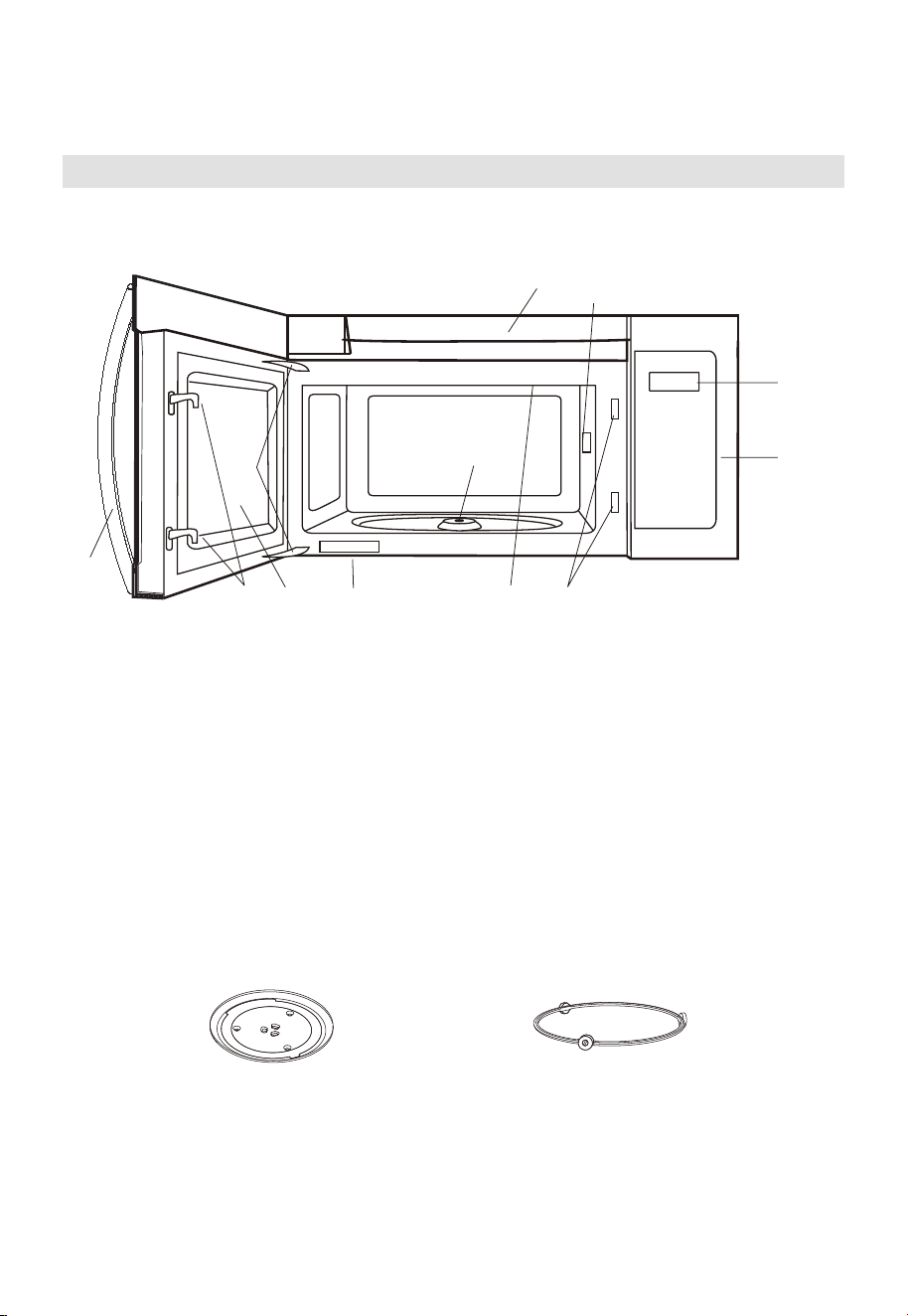
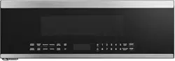
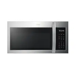
PRODUCT OVERVIEW
Setting Up Your Oven
PART NAMES
9
8
10
3
65
4
11
16
2
7
1. Microwave oven door with see-through window
2. Door hinges
3. Waveguide cover: DO NOT REMOVE.
4. Turntable motor shaft
5. Microwave oven light
It will light when microwave oven is operating or door is open.
6. Safety door latches
The microwave oven will not operate unless the door is securely closed.
7. Handle
8. Control panel
9.
10. Ventilation openings
11. Rating label
Glass turntable Turntable Ring Assembly
Display
EN-12
PRODUCT INSTALLATION
Important Safety Instructions
This product requires a three-prong grounded outlet. The installer must perform a
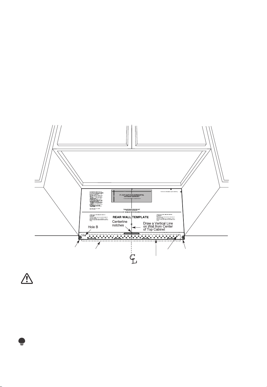
ground continuity check on the power outlet box before beginning the installation to
ensure that the outlet box is properly grounded. If not properly grounded, or if the outlet
box does not meet electrical requirements noted (under ELECTRICAL REQUIREMENTS),
a qualified electrician should be employed to correct any deficiencies.
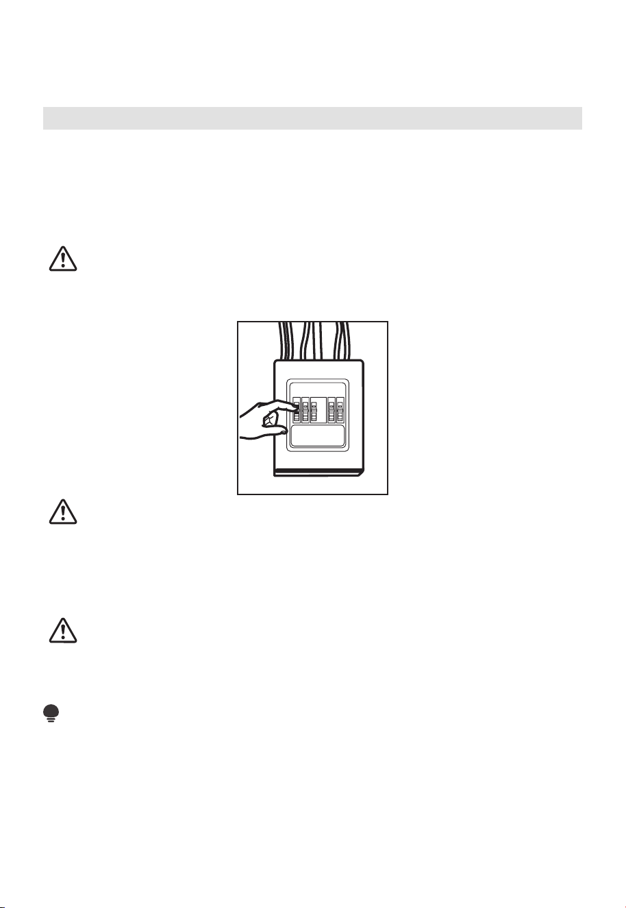
CAUTION:
For personal safety, remove house fuse or open circuit breaker before beginning
installation to avoid severe or fatal shock injury.
CAUTION:
For personal safety, the mounting surface must be capable of supporting the cabinet
load, in addition to the added weight of this 63–85 pound (28.5–38.5 kg) product, plus
additional oven loads of up to 50 pounds (22.7 kg) or a total weight of 113–135 pounds
(51.3–61.2 kg).
CAUTION:
For personal safety, this product cannot be installed in cabinet arrangements such as an
island or a peninsula. It must be mounted to BOTH a top cabinet AND a wall.
NOTE:
For easier installation and personal safety, it is recommended that two people install this
product.
IMPORTANT – PLEASE READ CAREFULLY. FOR PERSONAL SAFETY, THIS APPLIANCE
MUST BE PROPERLY GROUNDED TO AVOID SEVERE OR FATAL SHOCK.
EN-13
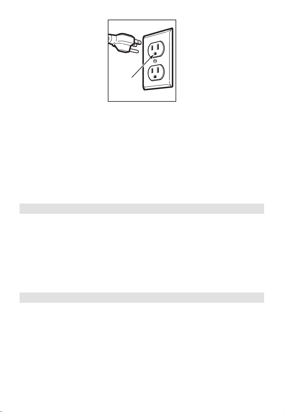
Ensure proper
ground exists
before use
The power cord of this appliance is equipped with a three-prong (grounding) plug
which mates with a standard three-prong (grounding) wall receptacle to minimize the
possibility of electric shock hazard from this appliance.
You should have the wall receptacle and circuit checked by a qualified electrician to
make sure the receptacle is properly grounded.
Where a standard two-prong wall receptacle is encountered, it is very important to have
it replaced with a properly grounded three-prong wall receptacle, installed by a qualified
electrician.
DO NOT, UNDER ANY CIRCUMSTANCES, CUT, DEFORM OR REMOVE ANY OF THE
PRONGS FROM THE POWER CORD. DO NOT USE WITH AN EXTENSION CORD.
Electrical Requirements
Product rating is 120 volts AC, 60 Hertz, 15 amps and 1.55 kilowatts. This product must
be connected to a seperate and dedicated supply circuit of the proper voltage and
frequency. Wire size must conform to the requirements of the National Electrical Code or
the prevailing local code for this kilowatt rating. The power supply cord and plug should
be brought to a seperate and dedicated 20 ampere branch circuit single grounded outlet.
The outlet box should be located in the cabinet above the microwave oven. The outler
box and supply circuit should be installed by a qualifed electrician and conform to the
National Electrical Code or the prevailing local code.
Damage—Shipment/Installation
1. If the unit is damaged in shipment, return the unit to the store in which it was bought
for repair or replacement.
2. If the unit is damaged by the customer, repair or replacement is the responsibility of
the custome
r.
3. If the unit is damaged by the installer (if other than the customer), repair or
replacement must be made by arrangement between customer and installer.
EN-14
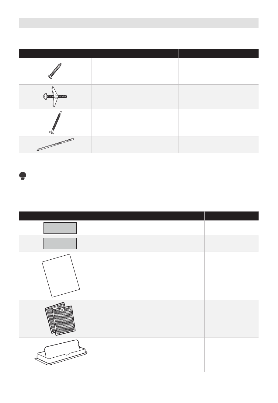
Parts Included
HARDWARE PACKET
PART QUANTITY
Wood Screws (
1
⁄
4
" x 2") 2
Toggle Bolts (and wing nuts)
(
3
⁄
16
" x 3")
2
Self-Aligning Machine Screws
(
1
⁄
4
"-28 x 3
1
⁄
4
")
3
Nylon Grommet
(for metal cabinets)
1
You will find the installation hardware contained in a packet with the unit. Check to make
sure you have all these parts.
NOTE:
Some extra parts are included.
ADDITIONAL PARTS
PART QUANTITY
Top Cabinet Template 1
Rear Wall Template 1
Separately Packed Grease Filters 2
Exhaust adaptor 1
USER
MANUAL
1
User Manual
EN-15
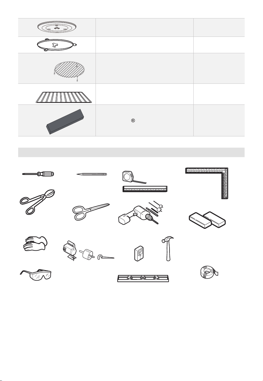
Glass Tray 1
Turntable Ring 1
For some models
Convection wire rack 1
For some models
Shelf 1
For some models
PureAir Microwave Filter 1
Tools You Will Need
# 1 Phillips screwdriver
Pencil
Ruler or tape measure
and straight edge
Carpenter square
(optional)
Tin snips (for cutting
damper, if required)
Hammer (optional)
Stud finder or
Gloves
Level
Saw (saber, hole or keyhole)
Filler blocks or scrap
wood pieces, if needed
for top cabinet spacing
(used on recessed bottom
cabinet installations only)
Duct and masking tape
Electric drill with
3
⁄16“,
1
⁄
2
“ and
5
⁄
8
“
drill bits
Scissors
(to cut template,
if necessary)
Safety goggles
EN-16
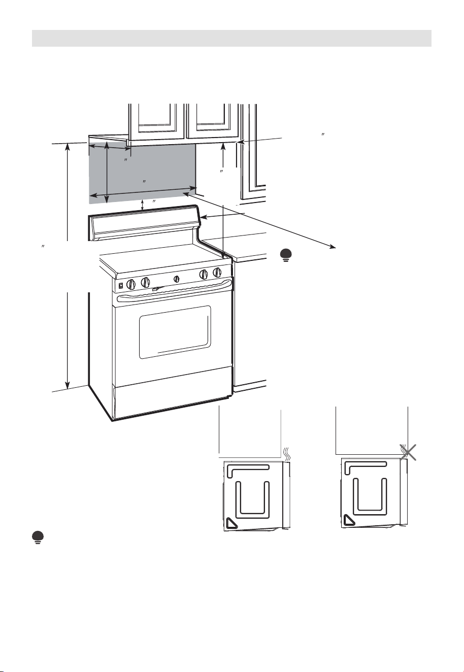
Mounting Space
MOUNTING SPACE
Bottom
Edge of
Cabinet
Needs
to
be 3 0 (76.2 cm)
or More from the
Cooking Surface
Backsplash
66 (167.6 cm)
or More from
the Floor to the
Top of the
Microwave
30 (76.2 cm)
2
(5.1cm)
30
min.
(76.2 cm)
16
1
⁄2
(41.9 cm)
13 Maximum (33 cm)
NOTE:
• The space between the cabinets must be 30" (76.2 cm)wide and free of obstructions.
• If you are going to vent your microwave oven to the outside, see Hood Exhaust
Section for exhaust duct preparation.
• When installing the microwave oven beneath smooth, flat cabinets, be careful to
follow the instructions on the top cabinet template for power cord clearance.
• As a guide to installation, see page 25 for Mounting Template Information.
• If the cabinet depth including
the cabinet doors is more than
13" then the unit must be
spaced out from wall using
adequate materials supporting
150 Ibs to allow proper top
vent air exhaust/intake.
“
NOTE:
EN-17
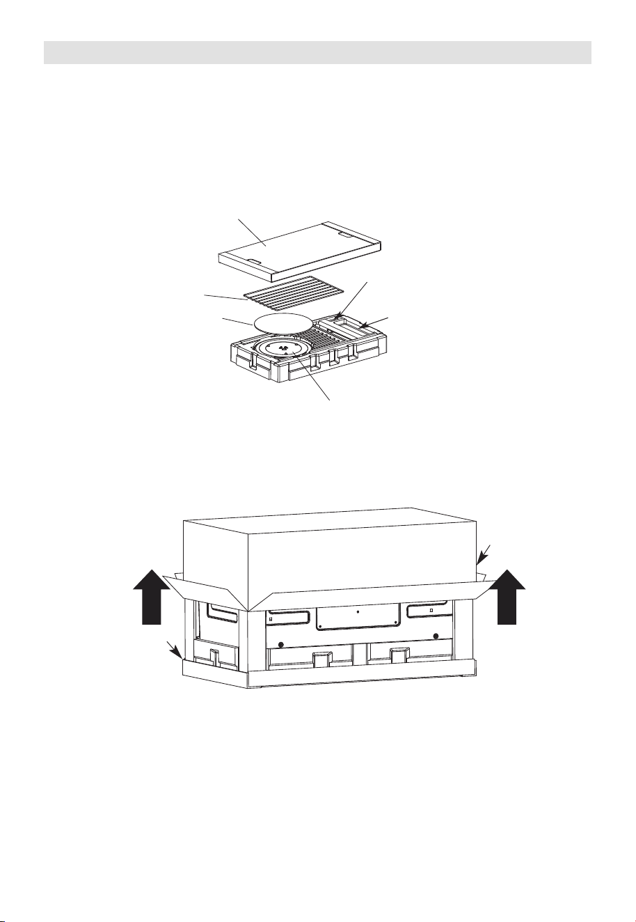
1. Placement Of The Mounting Plate
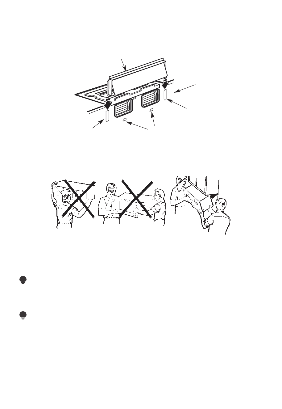
A. REMOVING THE MICROWAVE OVEN FROM THE CARTON/REMOVING THE
MOUNTING PLATE
1. Remove the top cover board, installation instructions, use and care, exhaust adapter,
turntable ring, shelf, filters, glass tray and the small hardwarebag. Do not remove the
Styrofoam protecting the front of the oven.
Filters and Turntable Ring below glass tray
Exhaust Adapter
Small Hardware Bag
Shelf (For
some models)
Top Cover Board
EPE Pad
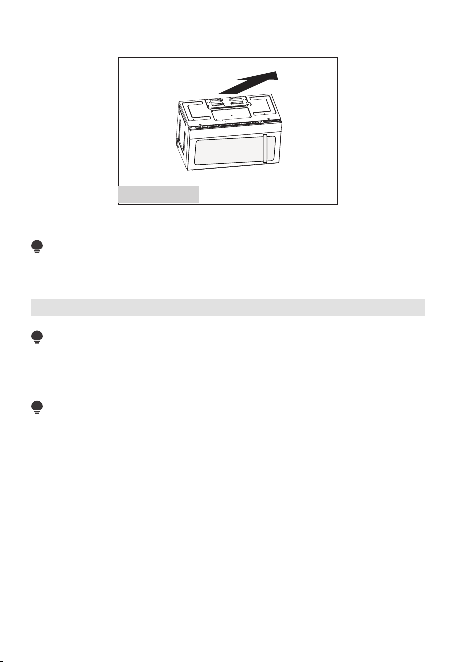
2. Fold back all 4 carton flaps fully against carton sides. Then carefully roll the oven and
carton over onto the top side. The oven should be resting in the Styrofoam.
Carton
Styrofoam
3.
Pull the carton up and off the oven.
EN-18
Screws
Screws
Mounting Plate
5. Remove the screws from each end of the mounting plate. This plate will be used as
the rear wall template and for mounting. Reinstall the screws into the holes where
they were removed.
B. FINDING THE WALL STUDS
Wall
Studs
Center
1. Find the studs, using one of the following methods:
- Stud finder – a magnetic device which locates nails.
- Use a hammer to tap lightly across the mounting surface to find a solid sound. This
will indicate a stud location.
2. After locating the stud(s), find the center by
probing the wall with a small nail to find the edges of the stud. Then place a mark
halfway between the edges. The center of any adjacent studs should be 16" (40.6 cm)
or 24" (61 cm) from this mark.
3. Draw a line down the center of the studs.
THE MICROWAVE MUST BE CONNECTED TO AT LEAST ONE WALL STUD.
4. Cut the middle of the outer protective plastic bag to remove the mounting plate
EN-19
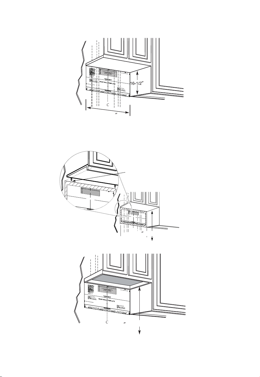
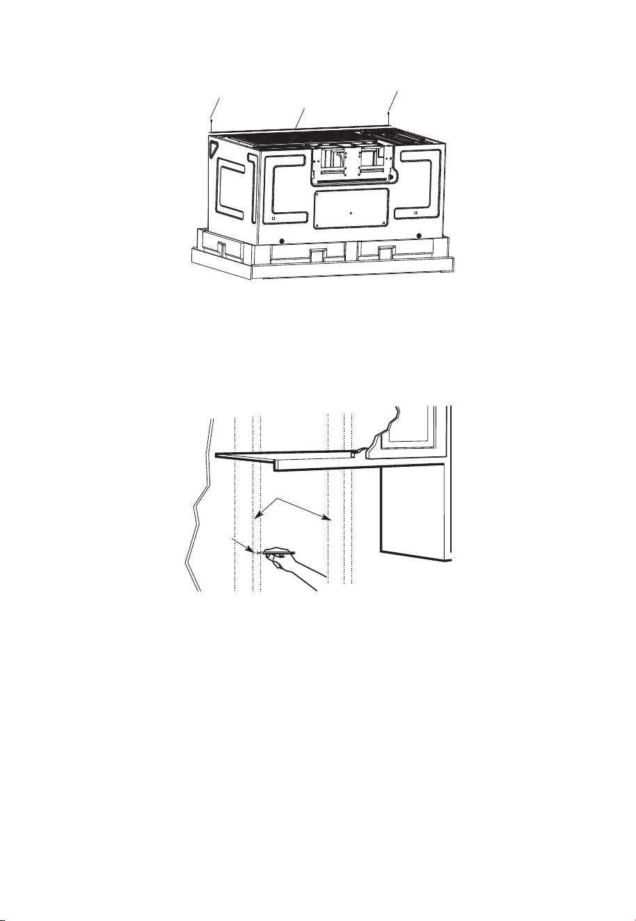
C. DETERMINING WALL PLATE LOCATION UNDER YOUR CABINET
Plate position-beneath flat bottom cabinet
At least 30
Draw a vertical line on the wall at the center of the 30" wide space.
Tape the Rear Wall Template onto the wall matching the centerline and touching the
bottom of the cabinet.
Plate position-beneath recessed bottom cabinet with front overhang
Draw a line on the
back wall equal to
the depth of the front
overhang.
Plate position-beneath framed recessed cabinet bottom
to Cooktop
30
Draw a vertical line on the wall at the center of the 30" space.
Tape the Rear Wall Template onto the wall matching the centerline and touching the
bottom cabinet frame.
C
3/
8"
TO
E
DGE
N
OT
E:
IT
I
S
VERY
IMP
O
R
T
A
NT
T
O
R
E
AD
A
ND
FO
LL
O
W
T
H
E
D
IR
E
C
T
I
ON
S
IN
T
H
E
IN
S
T
A
L
L
AT
I
ON
I
N
ST
R
UC
T
IO
N
S
B
E
F
OR
E P
R
O
CEE
DIN
G
WIT
H
T
HIS
RE
A
R
W
A
LL
T
E
MP
L
A
T
E.
Th
is
Re
a
r W
a
ll
Te
mpl
a
t
e
s
er
v
e
s
t
o p
o
s
it
io
n
t
h
e
bo
t
t
o
m
m
o
u
n
t
i
n
g
p
la
t
e
a
n
d
t
o
l
o
ca
t
e
t
h
e
h
o
ri
z
o
nt
a
l
e
x
h
au
st
o
u
t
le
t
.
1.
Us
e
a
le
v
e
l
t
o
c
h
ec
k
t
h
a
t
t
h
e
t
e
m
p
la
t
e
is
p
o
s
it
io
n
e
d
a
c
c
u
ra
t
e
ly
.
2
.
Lo
c
a
t
e
an
d
m
ar
k
at
le
a
s
t
o
n
e s
t
ud
o
n t
h
e
le
f
t
o
r
ri
ght
s
i
de
o
f
t
h
e
c
e
n
t
e
r
lin
e
.
I
t
is
im
po
rt
a
n
t
t
o
use at
l
e
a
st
o
ne
w
o
o
d
s
c
re
w
mo
u
n
te
d
f
ir
m
ly
in
a
s
t
u
d
to
s
u
p
p
o
r
t
the
w
e
ig
ht
o
f
t
h
e
m
ic
r
owa
v
e.
M
a
rk
t
w
o ad
d
it
i
o
na
l,
e
v
e
n
ly
s
pa
c
e
d
lo
c
at
io
n
s
for
th
e
s
u
pp
lie
d
t
o
gg
le
bo
lt
s
.
3
.
D
ril
l
h
o
le
s
in
t
he
m
a
rk
e
d
lo
c
a
t
io
n
s
.
Whe
re
th
e
re
is
a
s
t
ud,
d
r
ill
a
3
/
1
6
"
h
o
le
f
o
r
w
oo
d
s
c
re
w
s
.
F
or
h
o
le
s
th
at
d
o
n
ot
li
n
e
u
p
w
it
h
a
s
t
ud
,
d
rill
5
/
8
"
ho
le
s
fo
r
t
o
g
g
le
bo
lt
s.
D
O
N
O
T
I
NS
TALL
T
H
E
MO
U
N
T
I
N
G
P
L
A
T
E
AT
TH
IS
T
I
M
E
.
4
.
R
e
m
o
v
e
t
h
e
te
m
p
la
te
f
ro
m
t
h
e
r
e
ar
w
a
l
l.
5
.
R
e
v
i
e
w
t
h
e
I
n
s
t
a
lla
t
io
n
I
n
s
t
r
u
ct
ion
b
o
o
k
f
o
r
y
ou
r
i
n
sta
lla
t
io
n
s
i
t
u
at
io
n
.
L
o
c
a
te an
d
ma
rk
h
o
l
es
to
a
li
g
n w
it
h
h
o
l
e
s
i
n
the
mo
u
n
t
in
g
p
l
a
te.
I
MP
O
R
T
ANT
:
LO
C
AT
E
A
T
LEAS
T
ONE
S
T
U
D ON E
I
T
H
ER
S
I
DE
O
F
T
HE CE
NTE
R
LIN
E.
MA
RK
T
H
E
LOCAT
I
ON
FO
R
2
A
D
D
ITIO
NA
L, E
V
E
N
LY
S
P
AC
E
D TO
GG
LE B
OL
T
S IN
THE M
O
U
N
T
IN
G
P
L
AT
E
A
RE
A
.
Lo
ca
te a
n
d
ma
r
k ho
l
e
s to
a
lign with
h
oles in
t
h
e
mo
unt
i
ng p
l
a
t
e.
I
MP
O
RT
A
N
T:
LOCA
TE
AT
L
E
AST
ON
E
S
T
U
D
ON
EI
TH
E
R SID
E
O
F
T
H
E
C
ENT
E
RL
IN
E
.
MA
RK
TH
E LOC
A
TI
ON
F
OR
2 AD
D
I
T
I
ON
AL
,
E
V
E
N
L
Y
S
PAC
E
D
T
O
GG
L
E B
OL
T
S IN
T
H
E MO
U
N
T
IN
G
P
LAT
E
AR
E
A.
T
r
im
th
e
rea
r
w
a
l
l
te
m
p
l
ate
alo
ng t
h
e do
tte
d
lin
e
.
Trim
th
e r
ear
wa
l
l
te
m
p
l
a
te
a
lo
n
g
t
h
e
d
o
tte
d
line
.
1
2"
4
"
D
a
r
le
vu
e
lt
a
a
la
h
o
ja
p
a
ra
c
on
s
u
l
t
a
r
la
v
e
r
si
ó
n
e
n
E
sp
a
ño
l.
3/8
"
TO EDGE
N
O
TE
:
I
T
IS
VER
Y
IMPOR
T
AN
T T
O
R
EAD
AN
D
FO
L
LO
W
TH
E D
IR
EC
TI
O
N
S
I
N
T
H
E
I
N
ST
ALL
AT
IO
N
IN
ST
R
U
C
TI
O
N
S
B
EFO
R
E
PR
O
C
EED
IN
G
W
ITH
T
H
I
S
R
EAR
W
AL
L
T
EMPL
AT
E.
Th
is
R
e
a
r
W
a
ll
Te
mp
la
t
e s
er
v
e
s
to
p
o
s
it
i
o
n
th
e
b
o
t
to
m
mo
u
ntin
g
p
la
t
e
a
n
d
t
o l
o
c
at
e
th
e h
o
r
iz
on
ta
l e
x
h
a
us
t
ou
tle
t.
1
.
U
s
e
a
l
ev
e
l to
c
he
c
k
th
a
t
th
e
te
mp
la
t
e is
p
o
sitio
n
e
d
a
c
c
u
r
a
t
e
ly
.
2
.
L
o
c
a
te
a
n
d
ma
r
k
a
t le
a
s
t
o
n
e
s
t
u
d
o
n
t
he
le
ft
o
r
r
ig
ht
s
id
e
o
f
th
e c
e
n
te
r
l
in
e.
It
is
i
mp
o
r
ta
n
t t
o
u
s
e a
t le
a
s
t
o
n
e
w
o
o
d
s
c
r
e
w
mo
u
n
t
ed
f
ir
mly
in
a
s
tu
d
to
s
u
pp
o
r
t t
h
e
w
e
ig
h
t
o
f
th
e
mic
r
o
w
a
v
e
.
Ma
r
k
t
w
o
a
d
d
itio
na
l,
e
v
e
nl
y
s
p
a
ce
d
lo
c
a
tio
n
s
f
o
r
th
e
s
upp
li
e
d t
og
g
le
b
o
lts
.
3.
D
r
il
l h
ole
s
in
t
h
e
ma
r
k
e
d
lo
c
a
tio
n
s
.
W
h
e
r
e th
e
r
e
is
a
s
tu
d
, d
r
i
ll
a
3
/1
6"
h
o
le
fo
r
w
o
od
s
c
r
e
w
s
.
Fo
r
h
o
le
s
th
a
t d
o n
o
t lin
e
u
p
w
ith
a s
t
u
d
,
d
r
ill 5
/
8
" h
o
le
s fo
r
to
g
g
le
b
o
lts
.
D
O
N
O
T
IN
STA
L
L
TH
E
MO
U
N
TIN
G
P
L
ATE
AT TH
IS TIME
.
4
.
R
e
m
o
v
e
th
e
te
mp
la
te
fr
om
t
h
e
r
e
a
r
w
a
ll.
5
.
R
e
v
ie
w
t
he
In
s
ta
ll
atio
n
In
s
tru
c
t
io
n
bo
o
k fo
r
y
ou
r
in
sta
lla
tio
n
s
itu
a
tio
n.
Lo
cate an
d
ma
rk
h
ol
es t
o al
i
g
n w
it
h
h
ol
e
s
i
n t
h
e
mo
unti
n
g
pl
a
t
e
.
I
M
PO
R
T
AN
T
:
LOC
A
TE AT
LEAST
ONE ST
U
D
ON
EI
TH
ER
SI
D
E
OF
TH
E C
EN
TER
LIN
E.
MAR
K
T
H
E
LOC
ATIO
N
FO
R
2
AD
D
I
T
I
ON
AL
,
EVEN
L
Y
SPAC
ED
T
OG
GLE
BO
L
T
S
I
N
TH
E
MOUN
T
I
N
G
PLATE
AR
EA
.
Lo
cate
an
d
ma
rk
h
ol
es t
o al
i
g
n w
i
t
h
h
ol
e
s
in t
h
e
mo
un
tin
g pl
a
t
e
.
IMPO
R
T
AN
T:
LOC
AT
E AT
LEAS
T
ON
E ST
U
D
ON
EI
T
H
ER
SID
E
O
F
TH
E
C
EN
TE
R
LIN
E
.
MAR
K
T
H
E
LO
C
ATIO
N
F
O
R
2
AD
D
I
TI
ON
AL
, EVEN
L
Y
SPA
C
E
D
T
O
G
GLE
BO
L
T
S
I
N
TH
E
MO
U
N
TI
N
G
P
LAT
AR
EA.
Trim
th
e
r
e
ar
wall
t
em
p
lat
e
a
l
ong
th
e
d
otted
l
i
ne.
Trim
th
e
r
ear
wal
l
tem
pl
ate
a
l
ong
th
e
dotted
li
ne.
12
"
4"
D
arle
v
u
el
t
a
a
la
h
o
ja
p
a
r
a
c
o
n
s
u
lt
a
r
la
v
e
r
si
ó
n
e
n
E
s
p
añ
o
l.
to Cooktop
30
EN-20
Your cabinets may have decorative trim that interferes with the microwave installation.
Remove the decorative trim to install the microwave properly and to make it level.
THE MICROWAVE MUST BE LEVEL.
Use a level to make sure the cabinet bottom is level.
If the cabinets have a front overhang only, with no back or side frame, install the
mounting plate down the same distance as the front overhang depth. This will keep the
microwave level.
1. Measure the inside depth of the front overhang.
2. Draw a horizontal line on the back wall an equal distance below the cabinet bottom as
the inside depth of the front overhang.
3. For this type of installation with front overhang only, align the mounting tabs with this
horizontal line, not touching the cabinet bottom as described in Step D.
D. ALIGNING THE WALL PLATE
Area E
Hole A
Horizontal Line
Draw a horizontal line on wall at the
bottom of “Rear Wall Template”.
Horizontal Line
3/8" TO EDGE
CAUTION:
Wear gloves to avoid cutting fingers on sharp edges.
1. Draw a vertical line on the wall at the center of the 30" wide space.
2. Draw a horizontal line on the wall at the bottom of "Rear Wall Template".
3. Find a wall stud in area "E" of mounting plate Refer to section 1B. Finding the wall
studs.
4. For attaching the mounting plate into stud drill a 3/16" hole into wood stud. Drill a
5/8" hole for toggle bolt in 1 other location (Hole A or Hole B)
NOTE:
DO NOT MOUNT THE PLATE AT THIS TIME.
EN-21
NOTE:
Holes A and B are inside area E. If neither of Holes A and B are not in a stud, find a stud
somewhere in area E and draw a circle to line up with the stud. It is important to have at
least one wood screw mounted firmly in a stud to support the weight of the microwave.
Set the mounting plate aside.
2. Installation Types (Choose A, B or C)
This microwave oven is designed for adaptation to the following three types of
ventilation:
A. Outside Top Exhaust (Vertical Duct)
B. Outside Back Exhaust (Horizontal Duct)
C. Recirculating (Non-Vented Ductless)
NOTE:
This microwave is shipped assembled for Recirculating. Select the type of ventilation
required for your installation and proceed to that section.
A. OUTSIDE TOP EXHAUST (VERTICAL DUCT)
Adaptor in Place for
Outside Top Exhaust
See page 26
B. OUTSIDE BACK EXHAUST (HORIZONTAL DUCT)
See page 33
Adaptor Must Be
Moved to the Back for
Outside Back Exhaust
EN-22
C. RECIRCULATING (NON-VENTED DUCTLESS)
See page 41
Models are shipped for recirculating exhaust. Some models have a disposable charcoal
filter installed to help remove smoke and odors.
NOTE:
Read the next two pages only if you plan to vent your exhaust to the outside. If you plan
to recirculate the air back into the room, proceed to page 23-26.
Installation Instructions For External Exhaust Ducting
NOTE:
If you need to install ducts, note that the total duct length of 3
1
⁄
4
" x 10" (8.2 x 25.4 cm)
rectangular or 5" (12.7 cm)diameter/ 6" ” (15.2 cm) diameter round duct should not
exceed 120 equivalent feet (36.5 m).
Outside ventilation requires an EXTERNAL EXHAUST DUCT.Read the following carefully.
NOTE:
It is important that venting be installed using the most direct route and with as few
elbows as possible. This ensures clear venting of exhaust and helps prevent blockages.
Also, make sure dampers swing freely and nothing is blocking the ducts.
Exhaust connection:
The exhaust adaptor has been designed to mate with a standard 3
1
⁄
4
" x 10” (8.2 x 25.4
cm) rectangular duct.
If a round duct is required, a rectangular-to-round transition adaptor must be used.
A5 " (12.7cm)/ 6" (15.2cm) diameter duct is acceptable to use.
Maximum duct length:
For satisfactory air movement, the total duct length of 3
1
⁄
4
" x 10" (8.2 x 25.4 cm)
rectangular or 5" (12.7 cm) diameter/ 6 "(15.2 cm) diameter round duct should not
exceed 120 equivalent feet (36.5 m).
Elbows, transitions, wall and roof caps, etc., present additional resistance to airflow and
are equivalent to a section of straight duct which is longer than their actual physical size.
When calculating the total duct length, add the equivalent lengths of all transitions and
adaptors plus the length of all straight duct sections. The chart below shows you how
EN-23
to calculate total equivalent ductwork length using the approximate feet of equivalent
length of some typical ducts.
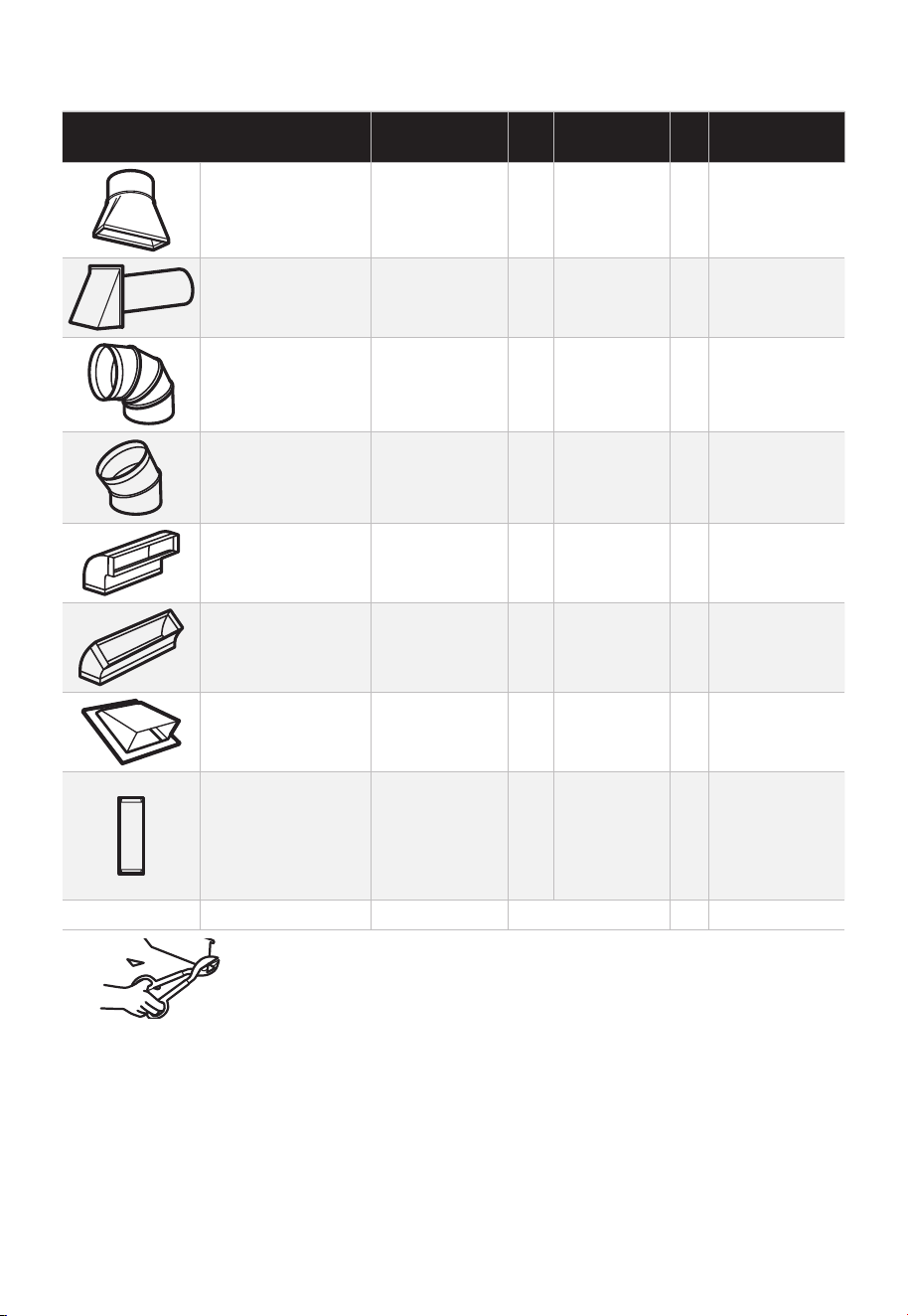
DUCT PIECES
EQUIVALENT
LENGTH
x
NUMBER
USED
=
EQUIVALENT
LENGTH
Rectangular-to-
Round Transition
Adaptor*
5 Ft. (1.5 m) x ( ) = Ft. or m
Wall Cap 40 Ft. (12.2 m) x ( ) = Ft. or m
90° Elbow 10 Ft. (3 m) x ( ) = Ft. or m
45° Elbow 5 Ft. (1.5 m) x ( ) = Ft. or m
90° Elbow 25 Ft. (7.6 m) x ( ) = Ft. or m
45° Elbow 5 Ft. (1.5 m) x ( ) = Ft. or m
Roof Cap 24 Ft. (7.3 m) x ( ) = Ft. or m
Straight Duct 6"
(15.2 cm) Round or
3
1
⁄
4
" x 10"
(8.2 x 25.4 cm
Rectangular)
1 Ft. (0.3 m) x ( ) = Ft. or m
Total Ductwork = Ft. or m
* IMPORTANT: If a rectangular-to-round transition adaptor is used,
the bottom corners of the damper will have to be cut to fit, using
the tin snips, in order to allow free movement of the damper.
Equivalent lengths of duct pieces are based on actual tests and reflect requirements for
good venting performance with any vent hood.
EN-24
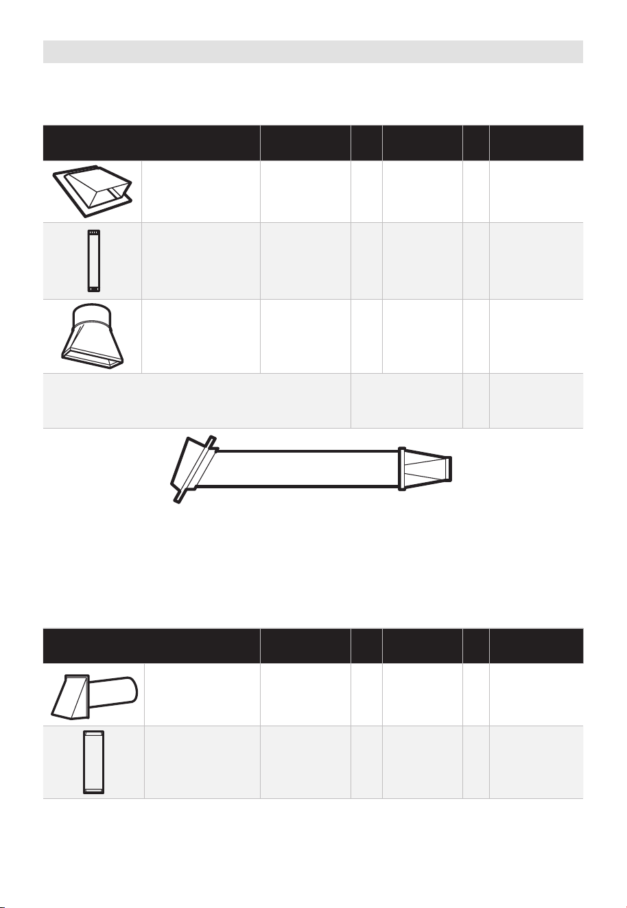
External Exhaust Ducting
OUTSIDE TOP EXHAUST (EXAMPLE ONLY)
The following chart describes an example of one possible ductwork installation.
DUCT PIECES
EQUIVALENT
LENGTH
x
NUMBER
USED
=
EQUIVALENT
LENGTH
Roof Cap 24 Ft. (7.3 m) x (1) = 24 Ft. (7.3 m)
12 Ft. (3.6 m)
Straight Duct
(6"/15.2 cm Round)
12 Ft. (3.6 m) x (1) = 12 Ft. (3.6 m)
Rectangular-to-
Round Transition
Adaptor*
5 Ft. (1.5 m) x (1) = 5 Ft. (1.5 m)
Equivalent lengths of duct pieces are based on
actual tests and reflect requirements for good
venting performance with any vent hood.
Total Length = 41 Ft. (12.5 m)
* IMPORTANT: If a rectangular-to-round transition adaptor is used, the bottom corners of
the damper will have to be cut to fit, using the tin snips, in order to allow free movement
of the damper.
OUTSIDE BACK EXHAUST (EXAMPLE ONLY)
The following chart describes an example of one possible ductwork installation.
DUCT PIECES
EQUIVALENT
LENGTH
x
NUMBER
USED
=
EQUIVALENT
LENGTH
Wall Cap 40 Ft. (12.2 m) x (1) = 40 Ft. (12.2 m)
3 Ft. Straight Duct
(3
1
⁄
4
"x 10"/8.2
x 25.4 cm
Rectangular)
3 Ft. (0.9 m) x (1) = 3 Ft. (0.9 m)
EN-25
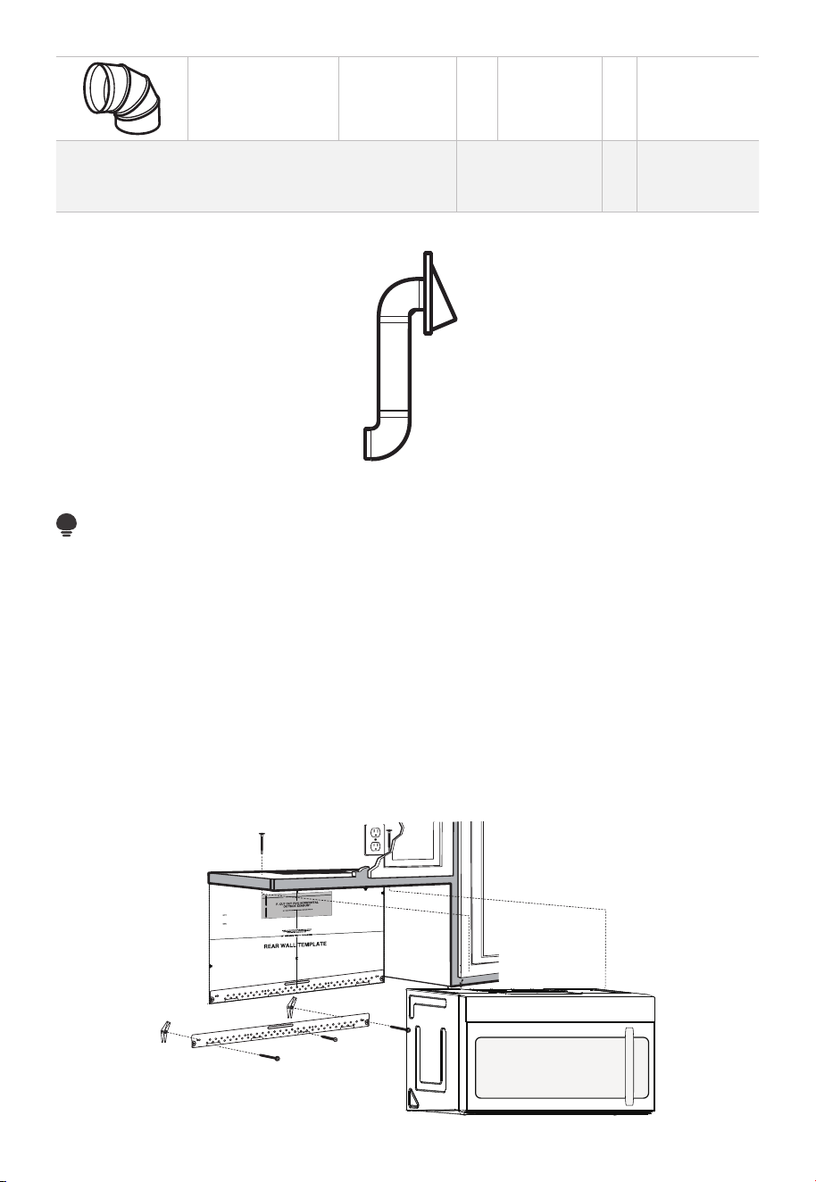
90° Elbow 10 Ft. (3 m) x (2) = 20 Ft. (3 m)
Equivalent lengths of duct pieces are based on
actual tests and reflect requirements for good
venting performance with any vent hood.
Total Length = 63 Ft. (19.2 m)
NOTE:
For back exhaust, care should be taken to align exhaust with space between studs, or
wall should be prepared at the time it is constructed by leaving enough space between
the wall studs to accommodate exhaust.
A. OUTSIDE TOP EXHAUST (Vertical Duct)
INSTALLATION OVERVIEW
A1. Attach Mounting Plate to wall
A2. Prepare Top Cabinet
A3. Configure Microwave Blower for Outside / Top Exhaust
A4. Check Damper Operation
A5. Mount Microwave Oven
A6. Adjust Exhaust Adapter
A7. Connect Duct-work
12"
4"
NO
TE:
READ AND F
O
I
T
I
S
V
ER
Y
LLO
I
W
MPO
T
HE
R
D
TA
NT
T
O
IRECTIO
IN THE INSTALLAT
I
O
N
I
NSTRU
CTIO
N
N
S
S
BE
F
O
RE
PRO
H
T
H
T
IWGNIDEE
C
IS
REAR
W
ALL
TEM
PL
A
TE
.
ll Te
mpl
a
te
s
er
v
es
t
o
p
1
ou
a
. Us
mo
u
tl
e
t.
nti
n
e
a l
T
hi
s
R
ea
g
p
rW
l
a
a
t
e
a
nd
to
lo
ca
te
th
e
h
ori
z
o
s
o
n
itio
t
a
n
l e
t
h
xh
e b
au
o
st
t
t
o
m
ioned
to
chec
k
tha
t
th
e
t
e
mplate
is pos
it
pl
a
r
k hol
es
to a
l
i
gn
wi
th hol
es
i
n t
he
L
oca
t
mounting
RTANT
e and m
:
ate
.
IMPO
E
AT LEA
THE CENT
HE LO
CATIO
L
OC
AT
E
RL
INE
ST
.
O
NE STUD ON EI
FO
EDIS
R
EH
T
SP
AC
E
AREA.
MAR
K
T
D T
O
GGLE
BO
NF
LT
S
O
IN
R 2 ADD
IT
THE MO
IO
UN
NA
TING
L, EV
EN
L
PLA
TE
Y
Trim the r
e
ar wa
l
l tem
plat
e a
long
the
dot
t
ed
l
ine.
k h
ole
s
to
a
l
ig
n w
ith h
ole
s
in t
he
m
ounting
L
oca
t
e a
n
d
mar
O
RT
AN
T
plate.
:
IMP
AT LEA
THE
CENT
HE
L
OCATIO
SP
LOCATE
ER
L
I
N
E.
IE N
O
D
UT
SE
NO
T
S
TH
ER
SI
D
E OF
AR
E
A.
MARK
ACED
T
T
OG
G
LE B
O
N
FO
LTS IN
R 2
AD
DITI
ON
THE
MO
UN
A
T
ING
L,
EV
ENL
PLATE
Y
Trim the rear
w
a
l
l te
m
pl
at
e a
long
t
h
e
do
tt
ed
li
n
e.
3/8"
TO
EDGE
2. L
o
c
c
cu
a
te
r
a
e
a
te
ly
v
nd
el
.
m
a
r
k a
t leas
t
o
d
u
t
s
e
n
o
n
th r
o
t
f
e
l
e
igh
t
si
d
e of
t
h
e c
ent
e
rl
ine
.
r
It is im
p
o
rta
nt
to
u
s
e
at
l
e
ast
o
n
e
woo
d
sc
rew
mo
ro
unte
d
wa
v
fi
e.
r
M
ml
y
ar
i
k
n
t
a
w
s
o
a
t
ud
d
di
t
i
to
s
up
p
ona
l,
ev
or
en
t
the
w
ly
s
e
pa
ight
ced
e mic
f
e
o
r
s
i
n
t
he
t
h
s
e
u
m
ppl
ar
k
ied to
ed
l
o
g
c
g
le bo
l
ati
on
t
s
s
.
.
Wh
er
e t
her
e is
lo
o
f
a
c
th
3. Dr
a
th
s
i
tio
at
ll
tu
n
h
d
s
ol
d
ri
l
l
a
3/1
6"
h
ol
e fo
r
w
oo
d
sc
r
e
w
s
.
F
o
r
h
o
l
es
do
,
hti
w
p
u
e
a
stud,
d
ri
l
l
5
/8
" h
ol
es
fo
r
e b
o
n
o
lts
t
li
n
.
NO
T
t
oggl
IN
STAL
L
T
HE
MO
U
N
TI
NG
P
L
ATE
AT
4.
R
e
T
m
HI
S
T
D
O
th
IME.
e te
o
v
e
mp
l
a
te fr
omth
e r
ea
r
wall
.
5.Re
v
ie
w
the I
n
s
ta
ll
a
tsnIn
oi
t r
uc
t
i
on b
o
o
k
for y
ou
r
inst
al
l
a
t
io
n s
it
ua
tio
n
.
Dar
le
vu
el
t
a
ala
ho
japa
raco
ns
ul
t
ar
la
v
e
r
si
ón
en
Espa
ño
l.
EN-26
IMPORTANT NOTES:
1. Make sure the screws for the Blower Motor and Blower Plate are securely tight-ened
when they are installed. This will help to prevent excessive vibration.
2. Make sure the Motor wiring has been properly routed and secured, and that the wires
are not pinched.
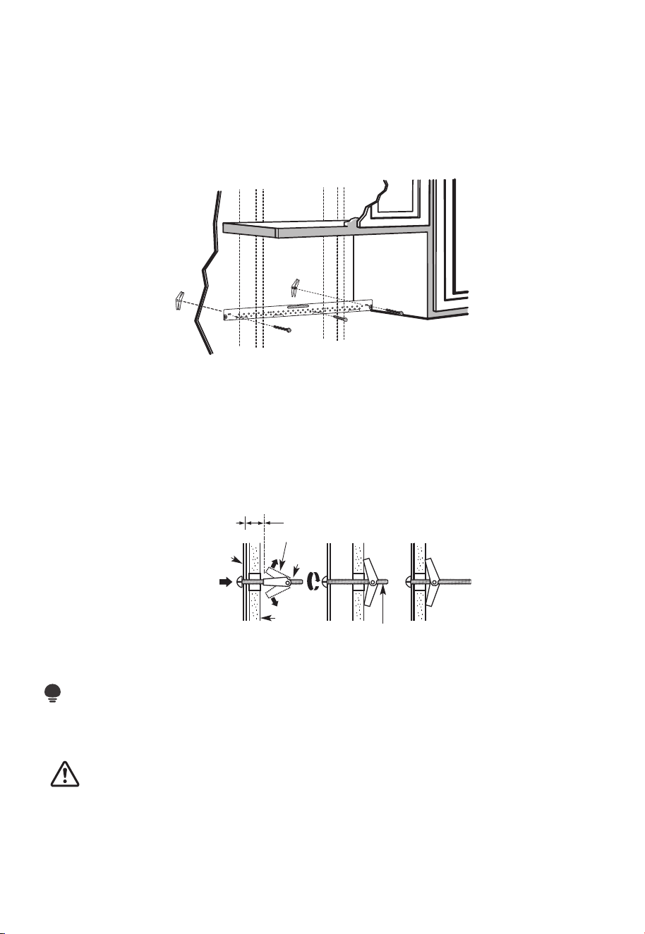
A1. ATTACH THE MOUNTING PLATE TO THE WALL
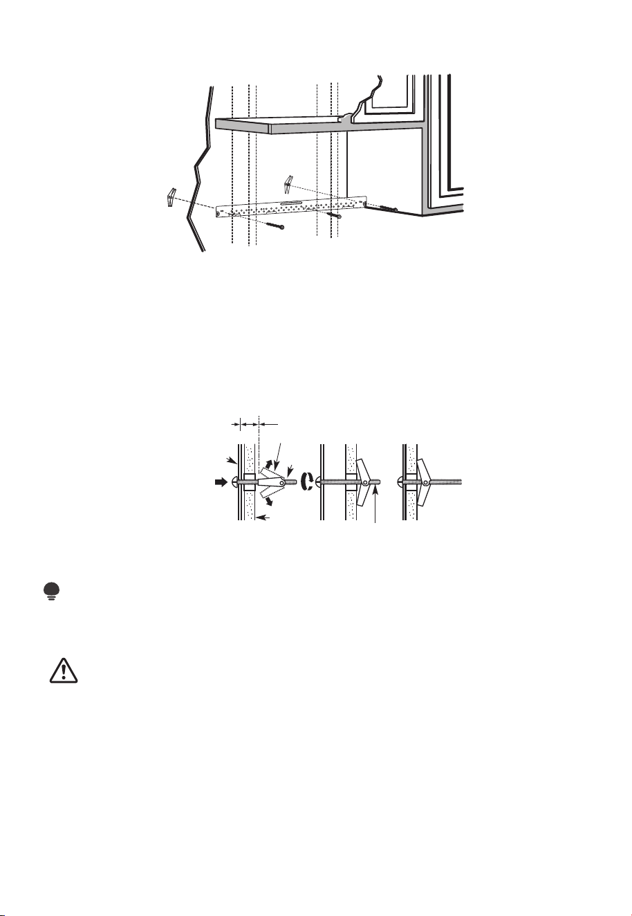
• Attach the plate to the wall using toggle bolts.
• At least one wood screw must be used to attach the plate to a wall stud.
1. Remove the toggle wings from the bolts
2. Insert the bolts into the mounting plate through the holes designated to go into
drywall and reattach the toggle wings to 3/4" (19mm) onto each bolt.
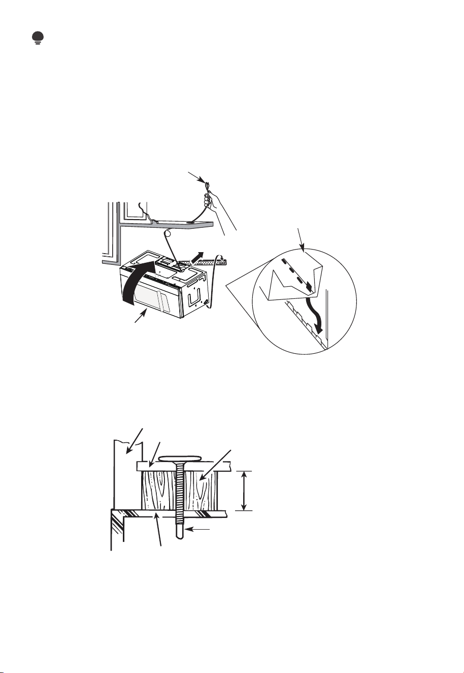
To use toggle bolts:
Wall
Mounting
Plate
Bolt End
Spacing for Toggles
More Than Wall
Thickness
Toggle
Bolt
Toggle Wings
3. Place the mounting plate against the wall and insert the toggle wings into the holes in
the wall to mount the plate.
NOTE:
Before tightening toggle bolts and wood screw, make sure the bottom of the mounting
plate touches the bottom of the cabinet when pushed flush against the wall and the plate
is properly centered under the cabinet.
CAUTION:
Be careful and avoid pinching fingers between the back of the mounting plate and the
wall.
4. Tighten all bolts. Pull the plate away from the wall to help tighten the bolts.
EN-27
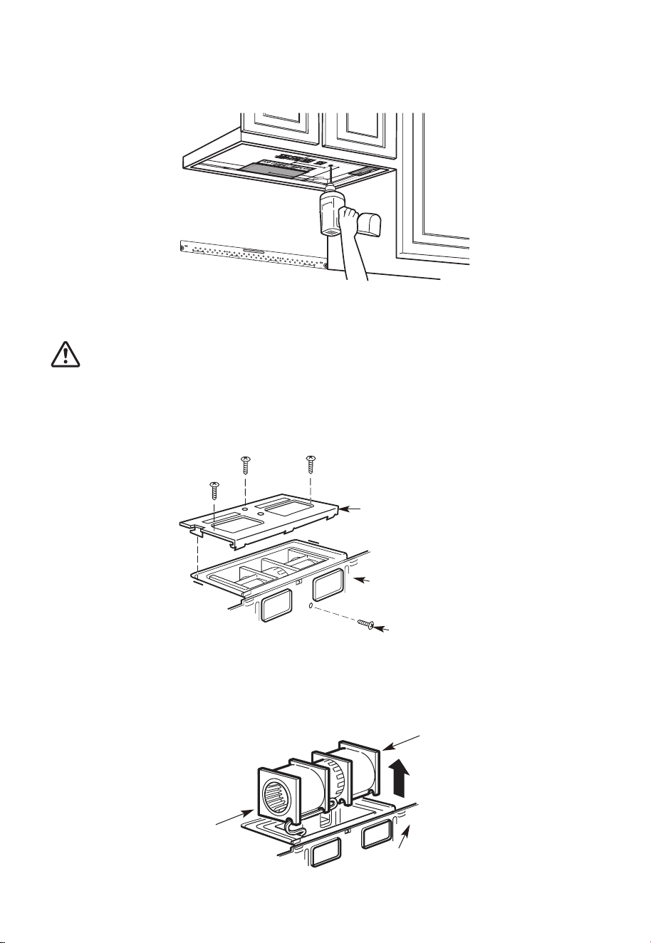
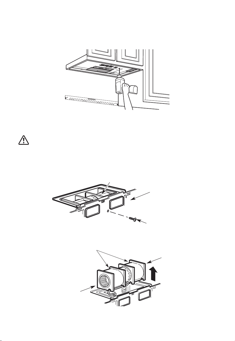
A2. USE TOP CABINET TEMPLATE FOR PREPARATION OF TOP CABINET
You need to drill holes for the top support screws, a hole large enough for the power
cord to fit through, and a cutout large enough for the exhaust adaptor.
1. Read the instructions on the TOP CABINET TEMPLATE.
2. Tape it underneath the top cabinet.
3. Drill the holes, following the instructions on the TOP CABINET TEMPLATE.
CAUTION:
Wear safety goggles when drilling holes in the cabinet bottom.
A3. ADAPTING MICROWA VE BLOWER FOR OUTSIDE TOP EXHAUST
1. Place the microwave in its upright position, with the top of the unit facing up.
Blower Plate
Blower Motor
Screw
Back of
Microwave
Remove the screw that holds the blower plate to the microwave. Remove and save the
screw holding the blower motor to the microwave.
2. Carefully pull out the blower unit. The wires will extend far enough to allow you to
adjust the blower unit.
Back of
Microwave
End B
End A
EN-28
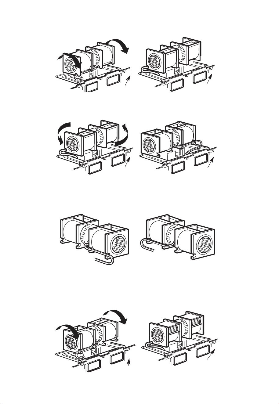
3. Roll the blower unit 90° so that fan blade openings are facing out the top of the
microwave.
Back of
Microwave
Back of
Microwave
Before Rotation After Rotation
4. Place the blower unit back into the opening.
Back of
Microwave
AFTER: Fan Blade
Openings Facing Top
CAUTION:
Do not pull or stretch the blower unit wiring. Make sure the wires are not pinched, and
that they are properly secured.
5. Secure blower unit to microwave with the screw removed in Step 1. Make sure the
screw is tight.
6. Replace blower plate with the screw removed in Step 1. Make sure the screw is tight.
Back of
Microwave
EN-29
7. Attach the exhaust adaptor to the top of the blower plate by sliding it into the guides
of the blower plate.
Back of
Microwave
Guide
Adaptor
Locking Tab
Push in securely until it is in the locking tabs. Take care to assure that the damper hinge
is installed so that the damper swings freely.
A4. CHECK FOR PROPER DAMPER OPERATION
Back of
Microwave
Exhaust Adaptor
Blower Plate
Damper
• Make sure tape securing damper is removed and damper pivots easily before
mounting microwave.
• You will need to make adjustments to assure proper alignment with your house
exhaust duct after the microwave is installed.
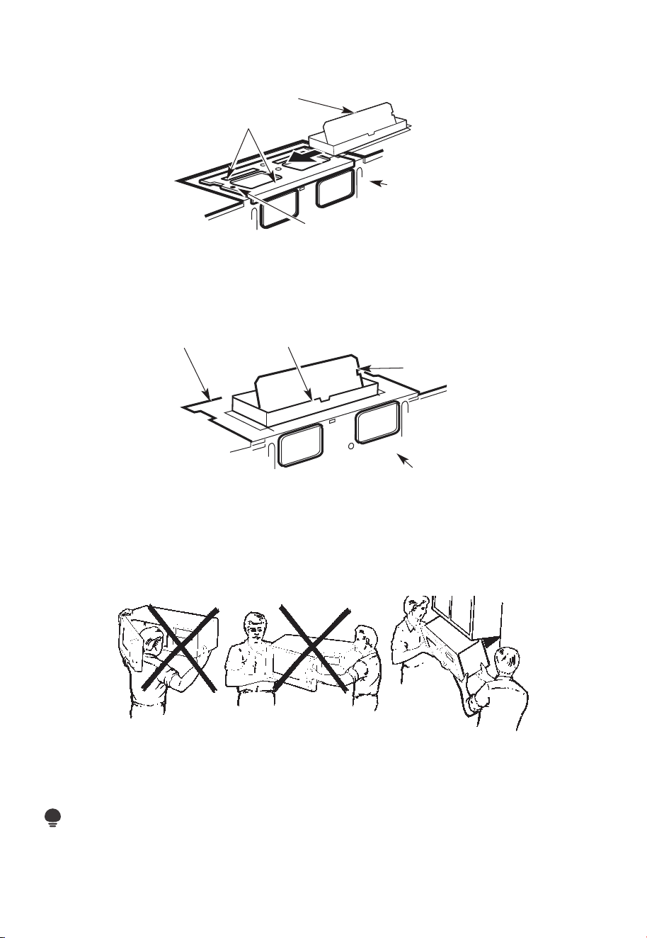
A5. MOUNT THE MICROWAVE OVEN
FOR EASIER INSTALLATION AND PERSONAL SAFETY, WE RECOMMEND THAT TWO
PEOPLE INSTALL THIS MICROWAVE OVEN.
IMPORTANT: Do not grip or use the handle or heat shield during installation. Do not
remove the cardboard spacers between the heat shield and door.
NOTE:
If your cabinet is metal, use the nylon grommet around the power cord hole to prevent
cutting of the cord.
EN-30
NOTE:
We recommend using filler blocks if the cabinet front hangs below the cabinet bottom
shelf.
IMPORTANT: If filler blocks are not used, case damage may occur from overtightening
screws.
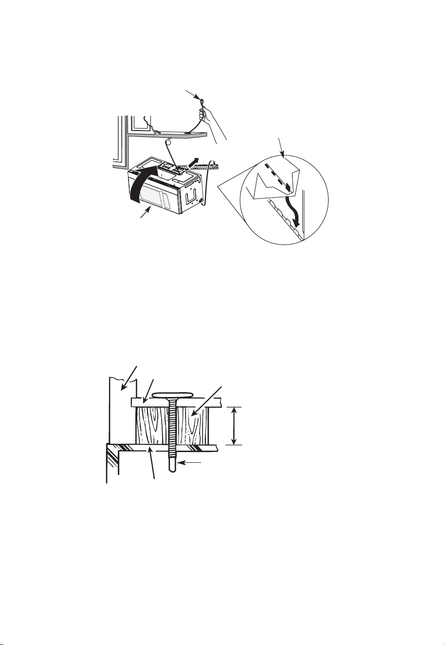
NOTE: When mounting the
microwave oven, thread power
cord through hole in bottom of
top cabinet. Keep it tight
throughout steps 1-3. Do not
pinch cord or lift oven by
pulling cord.
1. Lift microwave, tilt it
forward, and hook slots
at back bottom edge
onto four lower tabs of
mounting plate.
2 Rotate front of oven up
against cabinet bottom.
3. Insert a self-aligning screw through top center cabinet hole. Temporarily secure the
oven by turning the screw at least two full turns after the threads have engaged. (It
will be completely tightened later.) Be sure to keep power cord tight. Be careful not to
pinch the cord, especially when mounting flush to bottom of cabinet.
Microwave Oven Top
Cabinet Front
Cabinet Bottom Shelf
Filler Block
Equivalent to Depth
of Cabinet Recess
Self-Aligning Screw
4. Attach the microwave oven to the top cabinet.
EN-31
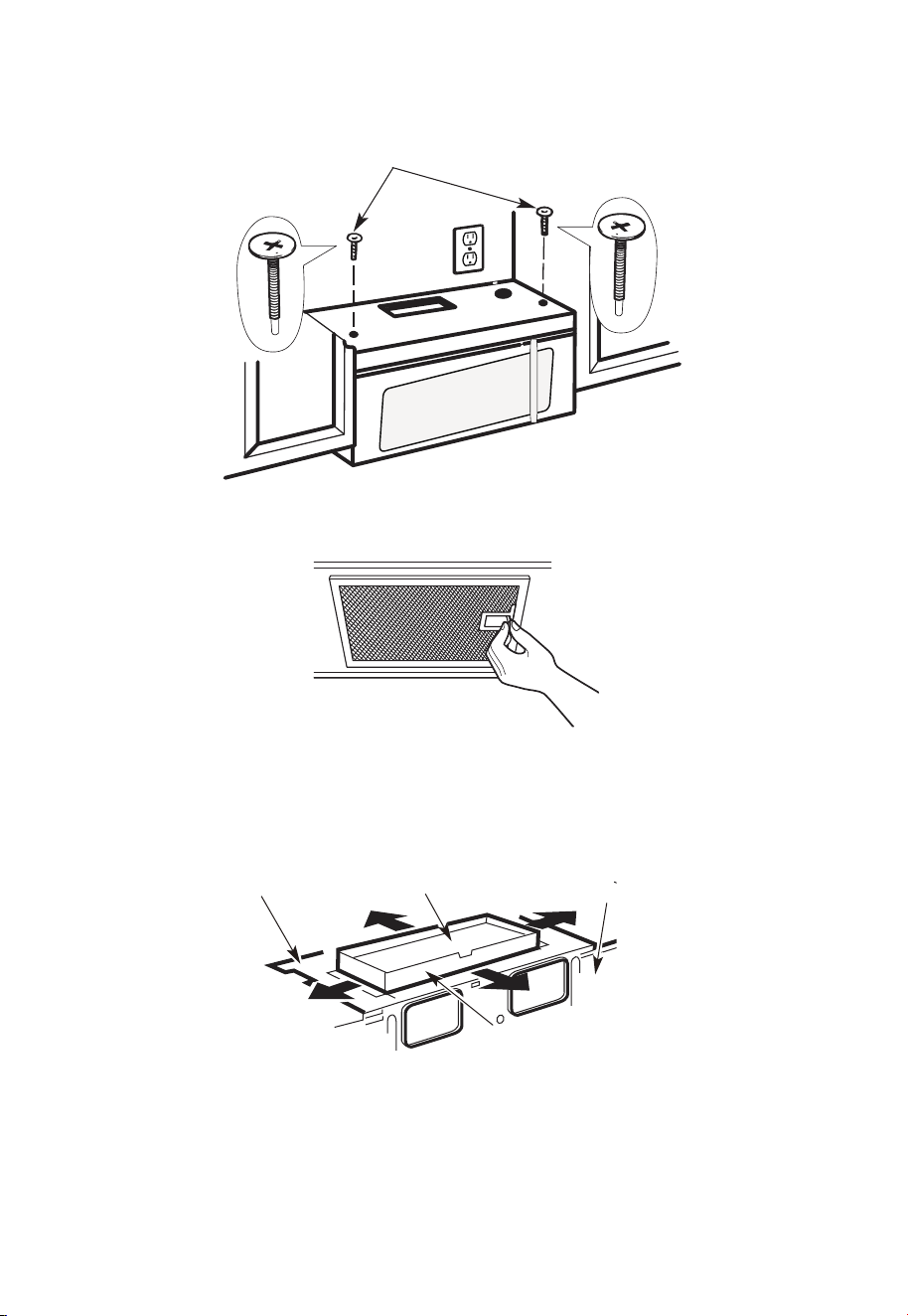
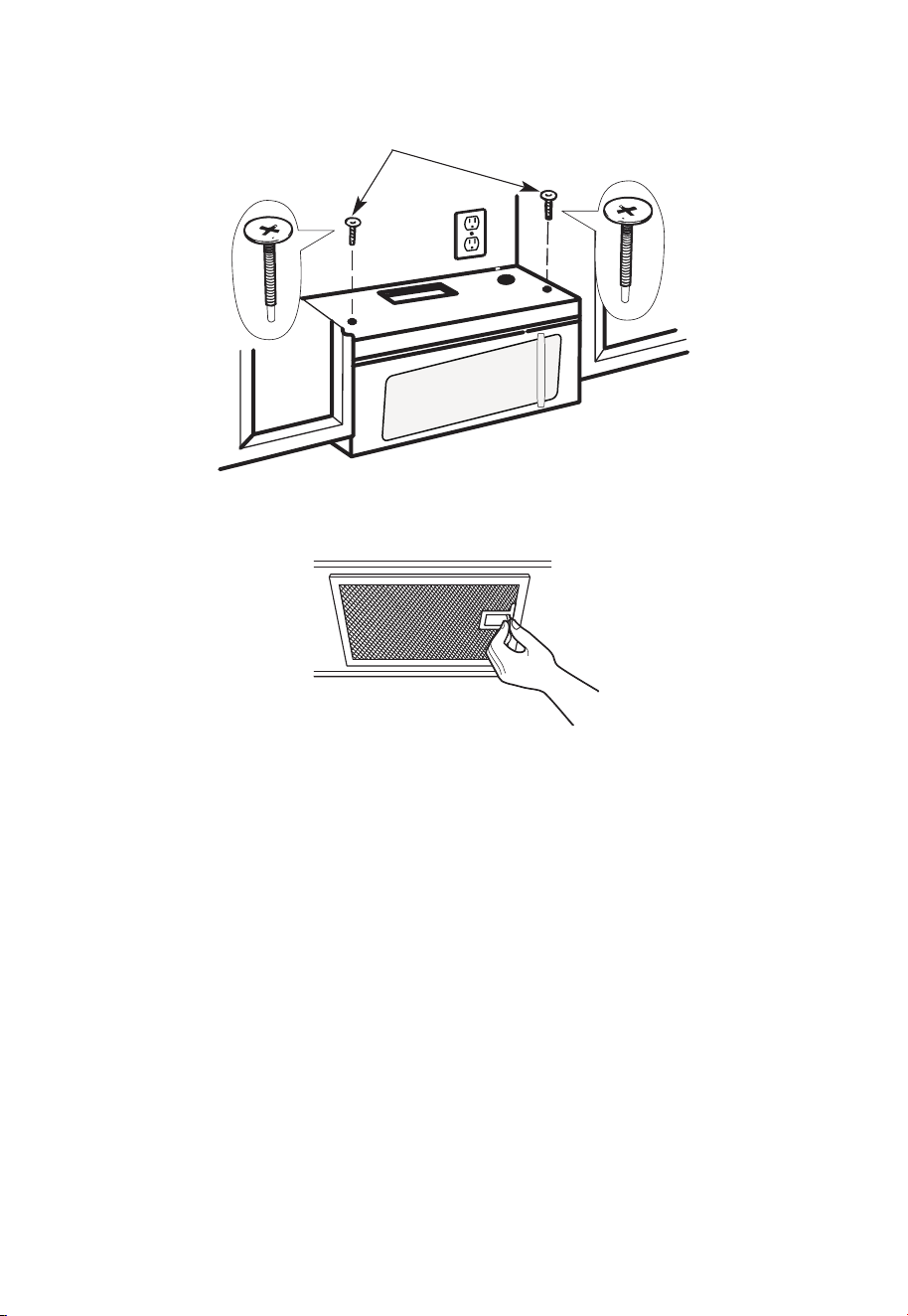
5.
Insert 2 self-aligning screws
through outer top cabinet
holes. Turn two full turns on
each screw.
6. Tighten the outer two screws to the top of the microwave oven. (While tightening
screws, hold the microwave oven in place against the wall and the top cabinet.)
7. Install grease filters. See the Use & Care Guide packed with the microwave.
A6. ADJUST THE EXHAUST ADAPTOR
Open the top cabinet and adjust the exhaust adapter to connect to the house duct.
For Front-to-Back or Side-
to-Side Adjustment, Slide
the Exhaust Adapter as
Needed
Back of
Blower Plate
Damper
Microwave
EN-32
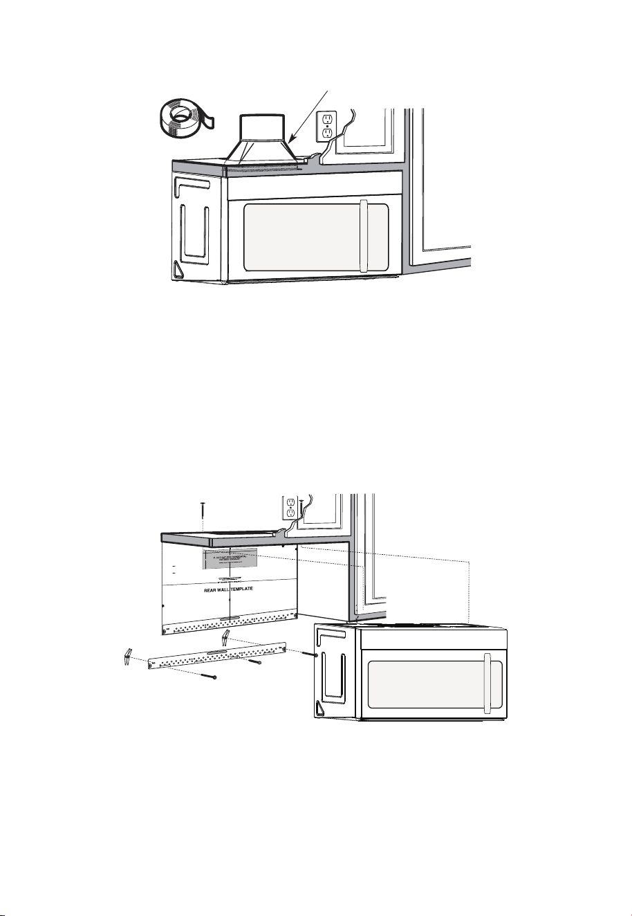
A7. CONNECTING DUCTWORK
House Duct
1. Extend the house duct down to connect to the exhaust adapter.
2. Seal exhaust duct joints using furnace duct tape for high temperature applications
B. OUTSIDE BACK EXHAUST (Horizontal Duct)
INSTALLATION OVERVIEW
B1. Prepare Rear Wall
B2. Remove Blower Plate
B3. Attach Mounting Plate to Wall B4. Prepare Top Cabinet
B5. Adjust Blower
B6. Mount the Microwave Oven
12"
4"
NO
TE
:
REA
D AND F
O
I
T
I
S
V
ER
Y
LLO
I
W
MPO
T
HE
R
D
TA
NT
T
O
IRECTIO
IN THE INSTALLAT
I
O
N
I
NSTRU
CTI
O
N
N
S
S
B
EF
O
RE PR
O
H
T
HTI
W
GN
I
DE
E
C
IS
REAR WA
L
L TEM
PL
A
TE
.
ll Te
mpl
a
te
s
er
v
es
t
o
p
1
ou
a
. Us
mo
u
tle
t.
nti
n
e
a l
T
h
is
R
ea
g
p
r
W
l
a
a
t
e
a
nd
to
lo
ca
te
th
e h
or
iz
o
s
o
n
itio
t
a
n
l e
t
h
xh
e b
au
o
st
t
t
o
m
ioned
to
chec
k tha
t
th
e
t
e
m
pl
at
e
is
p
osit
pl
ark
hol
es
to
ali
gn
wi
th holes
i
n t
he
L
ocat
mounting
RTANT
e and m
:
ate
.
IMP
O
E
AT LEA
THE
CENT
HE LO
CATIO
L
O
C
AT
ERL
INE
ST
.
O
NE STUD
ON EI
F
O
E
DISR
EH
T
SP
AC
E
AREA.
MAR
KT
D TOGGLE
BO
NF
LT
S
O
I
N
R 2 ADD
I
T
THE MO
IO
UN
NA
T
ING
L, EV
EN
L
P
LATE
Y
Trim the
r
e
ar wa
l
l tem
plat
e a
long
the
dott
e
d l
in
e.
k
h
ole
s
to
alig
n w
ith hole
s
in t
he
moun
ti
n
g
Loca
t
e a
n
d
mar
O
RTAN
T
plate.
:
IMP
AT LEA
T
HE CENT
HE
L
O
CATIO
SP
LOCA
T
E
ERLI
N
E
.
I
E
NO
D
U
TSE
NO T
S
T
H
E
R S
ID
E OF
AR
E
A.
MA
RK
ACED
T
T
OG
G
LE B
O
N
F
O
LTS IN
R 2 ADD
I
TION
T
H
E
M
O
UN
A
TING
L,
EV
ENL
P
LATE
Y
Trim the rear
w
al
l t
e
m
pl
a
t
e
a
long
t
he dotted
li
n
e.
3/8"
TO
EDGE
2. L
o
c
c
c
u
a
te
r
a
e
a
t
e
ly
v
nd
el
.
m
a
r
k a
t leas
t
o
d
u
t
s
e
n
o
n
th
r
o t
f
el
e
i
ght
si
d
e of
th
e c
ent
e
r
line
.
r
It is im
port
a
nt
to
us
e
at
l
ea
st
o
n
e
wo
od
sc
rew
mo
ro
unte
d
wa
v
fi
e.
r
M
ml
y
ar
i
k
n
t
a
w
s
o
a
t
ud
d
diti
to
s
up
p
ona
l,
ev
or
en
t
the
w
ly
s
e
pa
ight
ced
e mic
f
e
o
r
s
i
n
t
he
t
h
s
e
u
m
p
pl
ar
k
ied to
ed
l
o
g
c
g
le bo
l
ati
on
t
s
s
.
.
Wh
er
e t
her
e is
lo
o
f
a
c
th
3. Dr
a
th
s
i
tio
at
ll
tu
n
h
d
s
ol
d
ri
l
l
a
3/1
6"
h
ol
e fo
r
w
oo
d
sc
r
e
ws.
F
o
r
h
ol
es
do
,
ht
i
w
p
u
e
a
st
u
d,
d
ril
l
5
/8
" h
ol
es
fo
r
e b
o
n
o
lts
t
li
n
.
NO
T
t
oggl
IN
STAL
L
T
H
E
MO
U
N
TI
NG
PL
ATE
AT
4.
R
e
T
m
HI
S
T
D
O
th
IME.
e te
o
v
e
mpla
te fr
omth
e r
ea
r
wall
.
5.R
e
v
ie
w
the In
s
ta
ll
a
tsnIn
o
i
t r
uc
t
i
on b
o
o
k
for y
o
ur
ins
ta
lla
t
io
n s
it
ua
tio
n
.
Dar
le
vu
el
t
a
ala
ho
japa
raco
ns
ul
tar
la
v
e
rs
i
ón
en
Espa
ño
l.
IMPORTANT NOTES:
1. Make sure the screws for the blower motor and blower plate are securely tightened
when they are reinstalled. This will help pre-vent excessive vibration.
2. Make sure the motor wiring has been properly routed and se-cured and that the wires
are not pinched.
EN-33
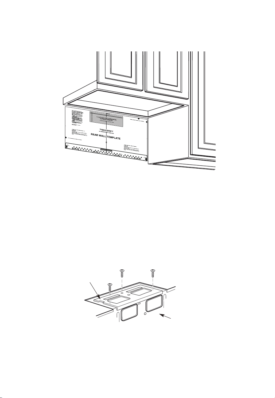
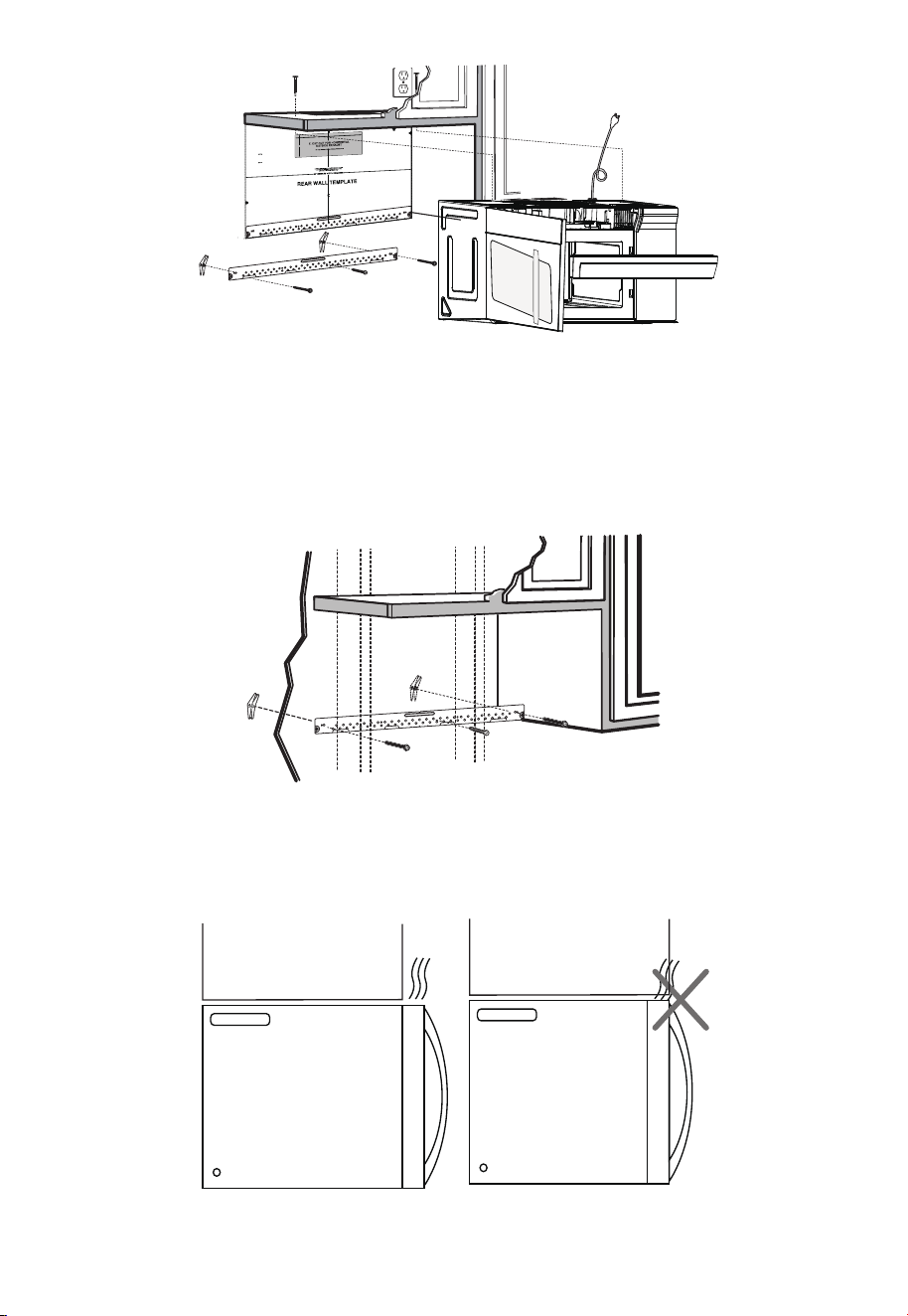
B1. PREPARING THE REAR WALL FOR OUTSIDE BACK EXHAUST
You need to cut an opening in the rear wall for outside exhaust.
1. Read the instructions on the REAR WALL TEMPLATE. Tape it to the rear wall.
2. Cut the opening, following the instructions of the
3. REAR WALL TEMPLATE.
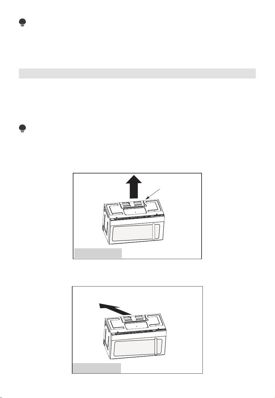
B2. REMOVE BLOWER PLATE
Remove and save the screw that holds the blower plate to the microwave. Lift off the
blower plate.
Microwave
Back of
Blower Plate
EN-34
B3. ATTACH THE MOUNTING PLATE TO THE WALL
Attach the plate to the wall using toggle bolts. At least one wood screw must be used to
attach the plate to a wall stud.
1. Remove the toggle wings from the bolts.
2. Insert the bolts into the mounting plate through the holes designated to go into
drywall and reattach the toggle wings to 3⁄4" (19 mm) onto each bolt.
To use toggle bolts:
Wall
Mounting
Plate
Bolt End
Spacing for Toggles
More Than Wall
Thickness
Toggle
Bolt
Toggle Wings
3. Place the mounting plate against the wall and insert the toggle wings into the holes in
the wall to mount the plate.
NOTE:
Before tightening toggle bolts and wood screw, make sure the bottom of the mounting
plate touch the bottom of the cabinet when pushed flush against the wall and that the
plate is properly centered under the cabinet.
CAUTION:
Be careful to avoid pinching fingers between the back of the mounting plate and the
wall.
4. Tighten all bolts. Pull the plate away from the wall to help tighten the bolts.
EN-35
1. Read the instructions on the TOP CABINET TEMPLATE.
2. Tape it underneath the top cabinet.
3. Drill the holes, following the instructions on the TOP CABINET TEMPLATE.
CAUTION:
Wear safety goggles when drilling holes in the cabinet bottom.
B5. ADAPTING MICROWAVE BLOWER FOR OUTSIDE BACK EXHAUST
1. Remove and save screw that holds blower motor to microwave.
Back of
Microwave
Blower Motor
Screw
Blower Motor
2. Carefully pull out the blower unit. The wires will extend far enough to allow you to
adjust the blower unit.
End B
End A
Before: Fan Blade
Openings Facing
Forward
B4. USE TOP CABINET TEMPLATE FOR PREPARATION OF TOP CABINET
You need to drill holes for the top sup-port screws and a hole large enough for the power
cord to fit through.
EN-36
Back of
Microwave
Back of
Microwave
Before Rotation After Rotation
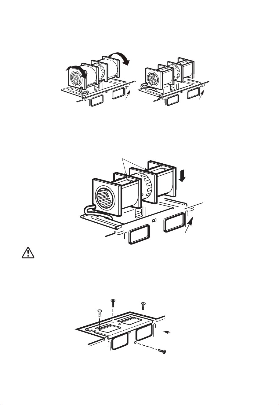
4. Rotate blower unit counterclockwise 180°.
Before Rotation After Rotation
Back of
Microwave
Back of
Microwave
5. Gently remove the wires from the grooves. Reroute the wires through grooves on
other side of the blower unit.
Before Rerouting After Rerouting
Wires Routed
Through Right Side
Wires Routed
Through Left Side
6. Rotate the blower unit 90° so that fan blade openings are facing out the back of the
mi-crowave.
Before Rolling After Rolling
Back of
Microwave
Back of
Microwave
3. Roll the blower unit 90°
EN-37
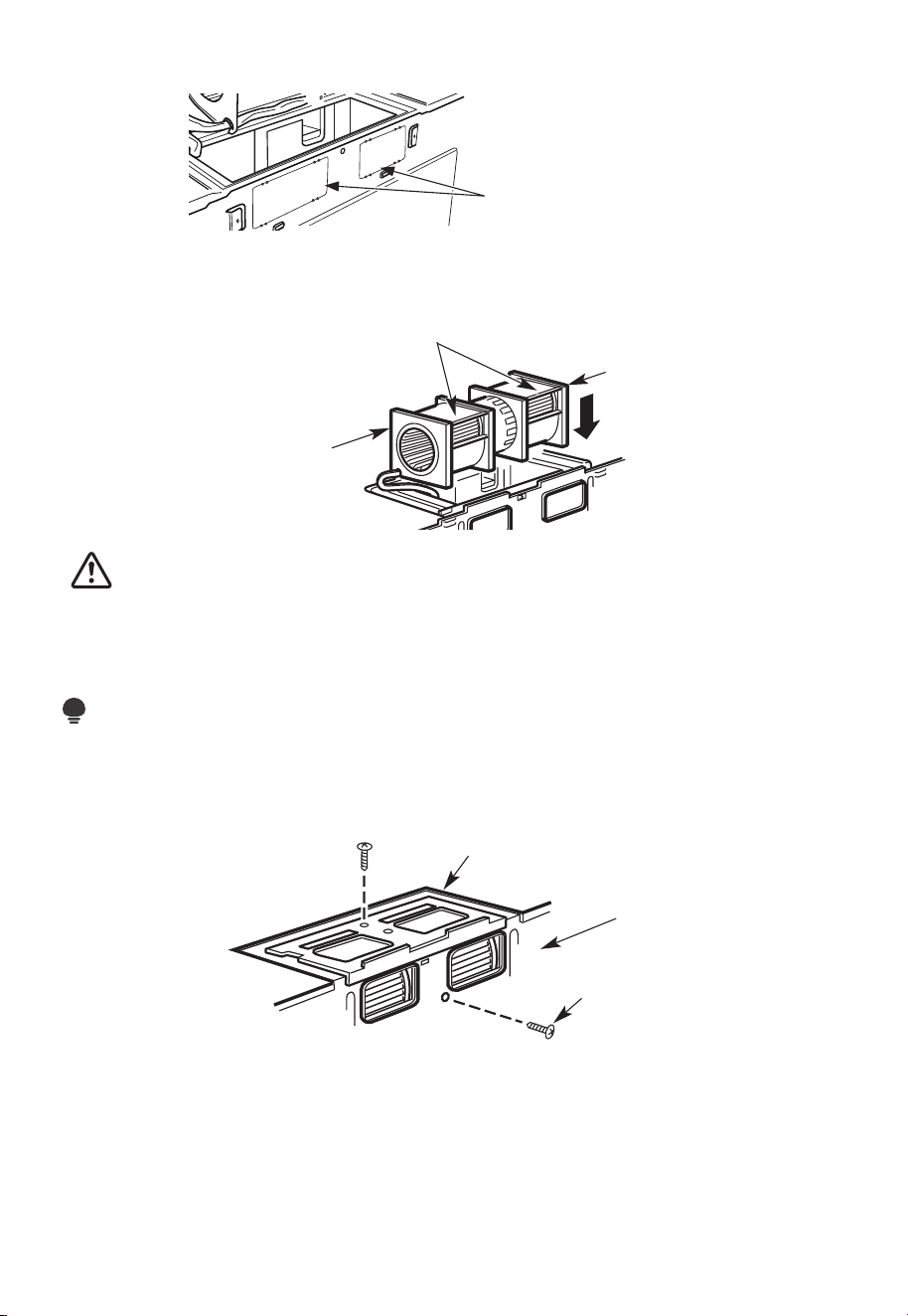
7. Remove the knockout plates in the back of the unit with snips. (for some models)
Knockout Plates:
Snip all 4 webs on
each knockout panel
and remove the metal
knockouts for rear airflow.
Please take care to
remove any sharp edges
created from removing
the knockout plates.
Back of Microwave
8. Place the blower unit back into the opening.
AFTER: Fan Blade
Openings Facing Back
End A
End B
CAUTION:
Do not pull or stretch the blower unit wiring. Make sure the wires are not pinched, and
that they are properly secured.
NOTE:
The blower unit exhaust openings should match exhaust openings on rear of microwave
oven.
9. Secure the blower unit to the microwave with the original screw.
Blower Plate
Blower Motor
Screw
Back of
Microwave
10. Replace the blower plate in the same position as before with the screw. Make sure the
screw is tight.
EN-38
Guide
Guide
Adaptor
Locking Tabs
Back of
Microwave
Push in securely until it is in the lower locking tabs. Take care to assure that the damper
hinge is installed so that it is at the top and that the damper swings freely.
B6. MOUNT THE MICROWAVE OVEN
FOR EASIER INSTALLATION AND PERSONAL SAFETY, WE RECOMMEND THAT TWO
PEOPLE INSTALL THIS MICROWAVE OVEN.
IMPORTANT: Do not grip or use the handle or heat shield during in-stallation. Do not
remove the cardboard spacers between the heat shield and door.
NOTE:
If your cabinet is metal, use the nylon grommet around the power cord hole to prevent
cutting of the cord.
NOTE:
We recommend using filler blocks of the cabinet front hangs below the cabinet bottom
shelf.
IMPORTANT: If filler blocks are not used, case damage may occur from over tightening
screws.
11. Attach the exhaust adaptor to the rear of the oven by sliding it into the guides at the
top center of the back of the oven.
EN-39
NOTE: When mounting the
microwave oven, thread power
cord through hole in bottom of
top cabinet. Keep it tight
throughout steps 1-3. Do not
pinch cord or lift oven by
pulling cord.
1. Lift microwave, tilt it
forward, and hook slots
at back bottom edge
onto four lower tabs of
mounting plate.
2. Rotate front of oven up
against cabinet bottom.
3. Insert self-aligning screw through top center cabi-net hole. Temporarily secure the
oven by turning the screw at least two full turns after the threads have engaged (it will
be completely tightened later). Be sure to keep the power cord tight. Be careful not to
pinch the cord, especially when mounting flush to bottom of cabinet.
Microwave Oven Top
Cabinet Front
Cabinet Bottom Shelf
Filler Block
Equivalent to Depth
of Cabinet Recess
Self-Aligning Screw
4. Attach the microwave oven to the top cabinet.
EN-40
5.
Insert 2 self-aligning screws
through outer top cabinet
holes. Turn two full turns on
each screw.
6. Tighten the outer two screws to the top of the microwave oven. (While tightening
screws, hold the microwave oven in place against the wall and the top cabinet.)
7. Install grease filters. See the Use & Care Guide that came with the microwave for more
information.
C. RECIRCULATING (non vented ductless)
INSTALLATION OVERVIEW
C1. Attach Mounting Plate to Wall
C2. Prepare Top Cabinet
C3. Check Blower Plate
C4. Mount the Microwave Oven
C5. Install or change Charcoal Filter
EN-41
12
"
4"
R
N
O
E
A
T
D
E
:
A
IT
N
I
D F
S
V
E
O
L
R
L
Y
O
I
W
M
P
T
O
H
E
R
T
D
A
I
R
N
E
T
C
T
T
I
O
O
I
N
T
H
E
IN
S
T
A
L
L
AT
I
O
N
I
N
ST
R
U
CT
I
O
N
N
S
S
BE
F
O
RE
P
R
O
C
E
E
D
I
N
G
W
I
T
H
T
H
I
S
R
E
A
R
W
A
LL
T
E
M
P
L
A
T
E
.
T
e
mp
l
a
t
e
s
e
rv
e
s
t
o
p
m
o
t
U
u
l
e
s
n
t
e
.
t
i
1
o
.
u
Th
i
s
R
e
n
a
g
r
p
l
W
a
a
t
e
l
l
a
n
d
t
o
l
o
c
a
t
h
t
e
e
h
o
r
i
z
o
o
s
i
t
n
t
i
o
a
l
n
e
t
x
h
h
e
a
b
u
s
o
t
t
t
o
m
e
t
o
c
h
e
c
k
t
h
a
t
t
h
e
t
e
m
p
l
a
t
e
i
s
p
o
s
i
t
i
o
n
d
L
oc
o
u
n
t
i
n
A
N
T
:
I
m
M
P
O
R
T
E
A
T
L
a
t
e
a
g
n
d
pl
a
m
te
a
.
r
k
h
o
l
es
to
a
li
g
n
w
i
t
h
h
ol
e
s
i
n
t
h
e
LOC
A
T
N
T
E
R
L
E
I
N
A
S
E
.
T
O
NES
T
U
D
O
N
E
I
T
H
E
R
S
ID
E
OF
T
H
E
C
E
H
E
L
O
CA
T
I
SP
AC
E
A
R
EA
.
MAR
K
T
D
TO
G
GLE
B
O
O
L
N
F
T
S
O
I
R
N
2
T
A
H
D
E
DI
M
T
O
IO
U
N
N
T
A
L
I
N
,
E
G
V
P
E
L
N
AT
L
Y
E
o
u
n
t
i
n
:
L
o
c
a
t
e
a
g
n
d
p
lat
m
a
e
.
rk
ho
le
s
t
o
a
l
i
gn
w
i
t
h
h
o
l
e
s
i
n
t
h
e
I
m
M
P
O
R
T
E
A
N
A
T
T
L
LO
C
A
T
NT
E
RL
E
I
A
N
E
ST
.
O
N
E
ST
UD
O
N
E
I
TH
E
R S
IDE
O
F
T
H
E
C
E
H
E
LO
CA
T
I
SP
A
C
A
RE
A
.
M
AR
K
E
D
T
T
O
G
G
LE
B
O
ON
F
L
T
S
O
R
IN
2
T
A
H
D
E
DIT
M
O
I
O
U
N
N
A
T
I
L
,
N
E
G
VE
P
L
A
NL
T
Y
E
T
r
im
t
h
e
re
ar
w
a
l
l
t
e
m
p
lat
e
a
l
on
g
t
h
e
d
o
t
t
ed
l
i
n
e.
3
/
8
"
T
O
EDG
E
Tri
m t
he
re
ar
wa
l
l
t
e
m
pla
t
e along
t
h
e d
ot
t
e
d
l
in
e.
L
a
o
c
c
c
a
u
a
t
r
e
a
t
l
e
v
a
el
n
y
e
d
.
l
2
.
m
a
r
k
a
t
l
e
a
s
t
o
n
e
s
t
u
d
o
n
t
h
e
l
e
f
t
o
r
r
i
g
h
t
s
i
d
e
o
f
t
h
e
c
e
n
t
e
rl
i
n
e
.
I
t
a
t
r
o
p
m
i
s
i
n
t
t
o
u
s
e
a
t
l
e
a
s
t
o
n
e
w
o
o
d
n
t
w
e
a
v
d
f
e
i
.
rm
M
ly
a
r
i
k
n
t
a
w
s
o
t
u
a
d
d
d
t
i
o
t
i
o
s
n
u
a
p
l
,
p
o
e
r
v
t
e
t
h
n
e
l
y
w
s
p
e
i
a
g
h
c
e
t
d
o
o
r
s
i
t
h
n
t
e s
h
u
e
p
m
p
l
a
i
r
e
d
k
e
t
d
o
l
g
o
g
c
l
a
e
t
b
io
o
l
n
t
s
s
.
.
W
h
e
re
t
h
e
r
e
i
s
l
s
3
o
f
o
.
c
r
c
t
t
t
a
D
a
e
h
h
o
t
r
i
e
s
w
g
a
i
l
o
t
t
l
g
u
n
m
l
m
d
h
o
d
s
i
e
o
o
,
c
r
f
l
u
d
e
r
i
l
l
a
3
/
16
"
h
o
l
e
f
o
r
w
o
o
d
s
c
r
e
w
s
.
F
o
r
h
o
l
e
s
n
n
e
u
p
w
it
h
a
s
t
u
d
,
d
r
i
ll
5
/
8
"
h
o
l
e
s
f
o
r
o
l
t
t
N
s
.
l
i
O
D
b
o
T
I
N
S
T
A
L
L
T
H
E
M
OU
N
T
I
N
G
P
L
A
TE
A
T
R
T
H
I
m
S
v
e
T
I
O
M
E
.
4
.
e
o
t
h
e
t
e
m
p
la
t
e
f
r
o
m
t
h
e
r
e
a
r
w
a
l
l
.
5
.
R
e
v
i
e
w
t
h
e
I
n
s
t
a
ll
a
t
i
o
n
In
s
t
ru
c
t
i
o
n
b
o
o
k
f
o
r
y
o
u
r
i
n
s
t
a
l
l
a
t
io
n
s
i
t
u
a
t
i
o
n
.
D
a
r
l
e
v
ue
l
t
a
a
la
ho
j
a
pa
r
a
c
o
n
s
u
l
t
a
r
l
a
v
e
r
s
i
ó
n
e
n
Es
p
a
ñ
o
l
.
IMPORTANT NOTES:
1. Make sure the screws for the blower motor and blower plate are securely tightened
when they are reinstalled. This will help prevent excessive vibration.
2. Make sure the motor wiring has been properly routed and secured and that the wires
are not pinched.
C1. ATTACH THE MOUNTING PLATE TO THE WALL
Attach the plate to the wall using toggle bolts. At least one wood screw must be used to
attach the plate to a wall stud.
If the cabinet depth including the cabinet doors is more than 13", then the unit must be
spaced out from wall using adequate materials supporting 150 Ibs to allow proper top
vent air exhaust/intake.
Cabinet Cabinet
EN-42
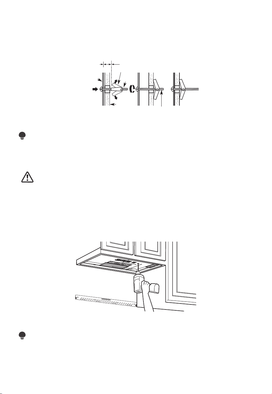
1. Remove the toggle wings from the bolts.
2. Insert the bolts into the mounting plate through the holes designated to go into
drywall and reattach the toggle wings 3/4" to (19mm) onto each bolt.
To use toggle bolts:
Wall
Mounting
Plate
Bolt End
Spacing for Toggles
More Than Wall
Thickness
Toggle
Bolt
Toggle Wings
3. Place the mounting plate against the wall and insert the toggle wings into the holes in
the wall to mount the plate.
NOTE:
Before tightening toggle bolts and wood
screw, make sure the bottom of the mounting plate touch the bottom of the cabinet
when pushed flush against the wall and that the plate is properly
centered under the cabinet.
CAUTION:
Be careful to avoid pinching fingers between the back of the mounting plate and the
wall.
4. Tighten all bolts. Pull the plate away from the wall to help tighten the bolts.
C2. USE TOP CABINET TEMPLATE FOR PREPARATION OF TOP CABINET
You need to drill holes for the top support screws and a hole large enough for the power
cord to fit through.
1. Read the instructions on the TOP CABINET TEMPLATE.
2. Tape it underneath the top cabinet.
NOTE:
Adjust top template accordingly if the microwave is being spaced out from the wall due
to cabinet depth (including cabinet doors) of more than 13".
Drill the holes following instructions on the TOP CABINET TEMPLATE.
EN-43
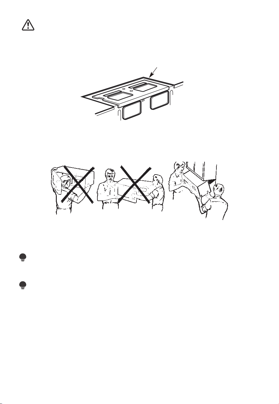
CAUTION:
Wear safety goggles when drilling holes in the cabinet bottom.
C3. CHECK BLOWER PLATE
Blower Plate
Place the microwave in its upright position, with the top of the unit facing up.
Check to see that the blower plate is cor-rectly installed on the unit.
C4. MOUNT THE MICROWAVE OVEN
FOR EASIER INSTALLATION AND PERSONAL SAFETY, WE RECOMMEND THAT TWO
PEOPLE INSTALL THIS MICROWAVE OVEN.
IMPORTANT: Do not grip or use the handle or heat shield during installation. Do not
remove the cardboard spacers between the heat shield and door.
NOTE:
If your cabinet is metal, use the nylon grommet around the power cord hole to prevent
cutting of the cord.
NOTE:
We recommend using filler blocks if the cabi-net front hangs below the cabinet bottom
shelf.
IMPORTANT: If filler blocks are not used, case dam-age may occur from over tightening
screws.
EN-44
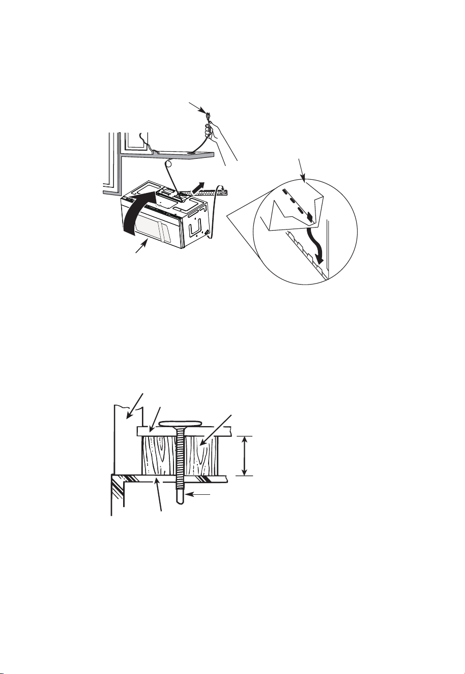
NOTE: When mounting the
microwave oven, thread power
cord through hole in bottom of
top cabinet. Keep it tight
throughout steps 1-3. Do not
pinch cord or lift oven by
pulling cord.
1. Lift microwave, tilt it
forward, and hook slots
at back bottom edge
onto four lower tabs of
mounting plate.
2. Rotate front of oven up
against cabinet bottom.
3. Insert a self-aligning screw through top center cabinet hole. Temporarily secure the
oven by turning the screw at least two full turns after the threads have engaged (It
will be completely tightened later.) Be sure to keep power cord tight. Be careful not to
pinch the cord, especially when mounting flush to bottom of cabinet.
Microwave Oven Top
Cabinet Front
Cabinet Bottom Shelf
Filler Block
Equivalent to Depth
of Cabinet Recess
Self-Aligning Screw
4. Attach the microwave oven to the top cabinet.
EN-45
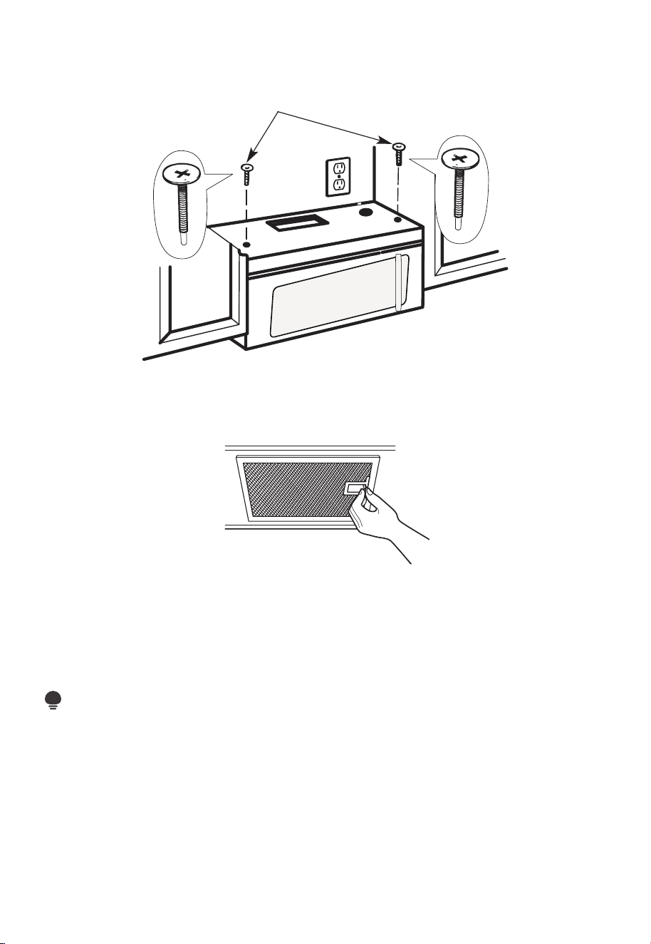
Insert 2 self-aligning screws
through
outer top cabinet holes. Turn two full
turns on each screw.
5
.
6. Tighten the outer two screws to the top of the microwave oven. (While tightening
screws, hold the microwave oven in place against the wall and the top cabinet.)
7. Install grease filters. See the Use & Care Guide packed with the microwave.
C5. INSTALLING OR CHANGING THE CHARCOAL FILTER (Some Models)
NOTE:
The charcoal filter is factory installed in some models. Refer to the Use & Care Guide to
see if yours is factory installed and for replacement information.
For models without the recirculation filter access door, follow these steps to replace or
install a charcoal filter:
1. Unplug microwave oven or disconnect power.
EN-46
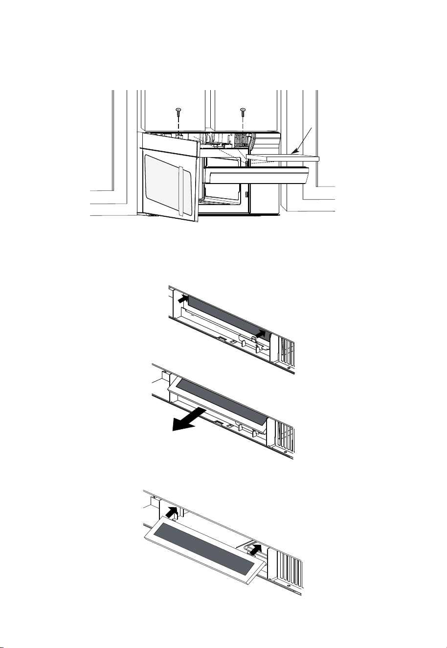
Charcoal
Filter
3. Remove the charcoal filter by pushing the top of the filter inwards,then pull it forward
out from the unit.
4. Slide the top of the new charcoal filter into the top of the filter cavity.
2. Open the microwave door and remove the two vent mounting screws located on top
of the microwave using a #1 Phillips screwdriver.
EN-47
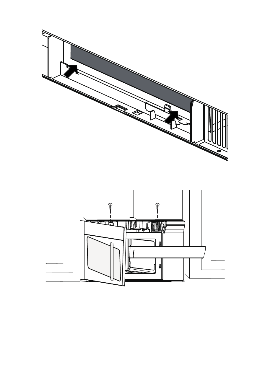
5. Press the bottom of charcoal filter to place it into the correct position.
6. Reinstall the vent by sliding the bottom of the vent into place. Push the vent top into
position and slide right into place. Replace the two vent mounting screws located on
top of the microwave using a #1 Phillips screwdriver.
7. Close the microwave door. Plug in microwave oven or reconnect power.
EN-48
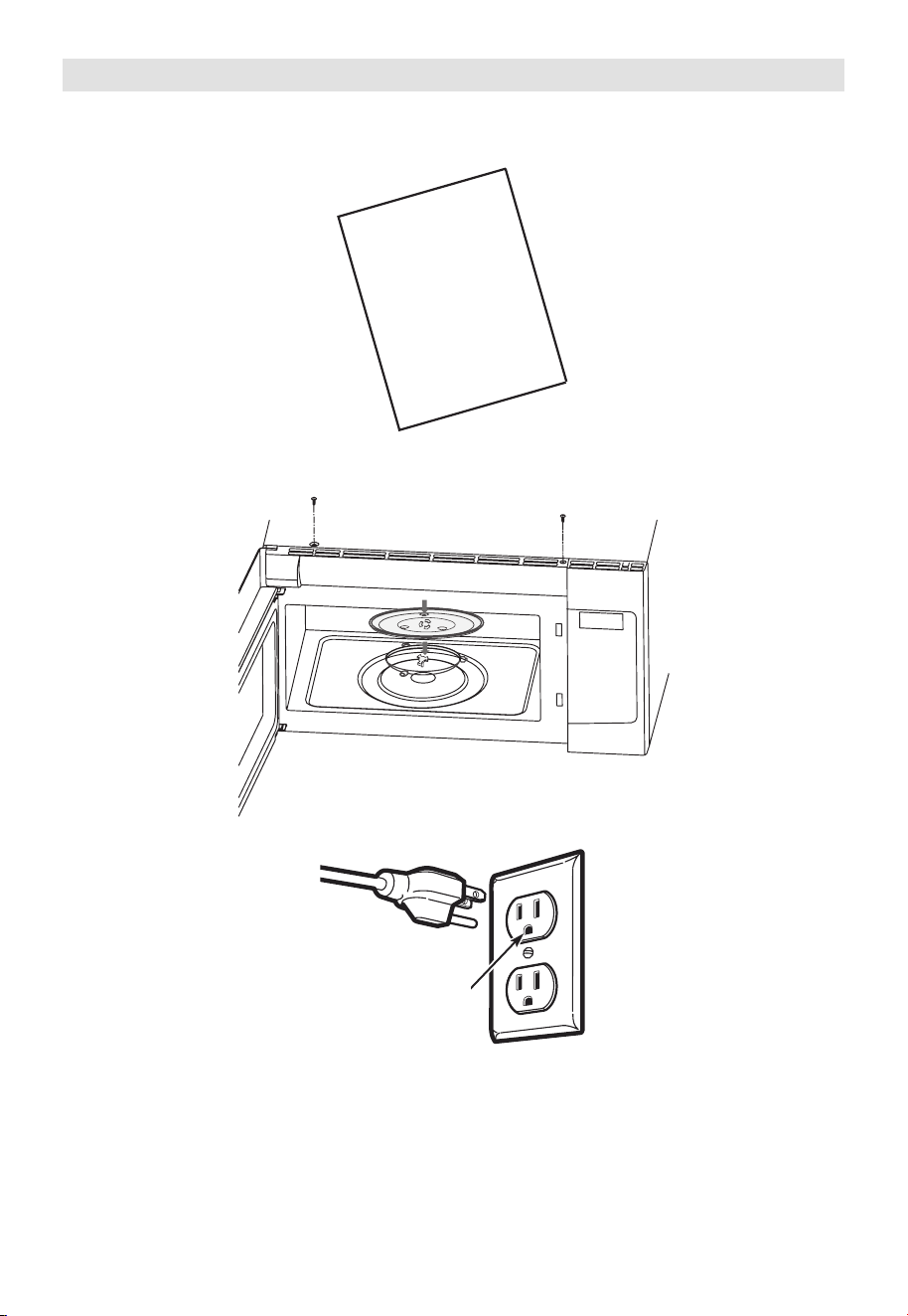
Before You Use Your Microwave
1. Make sure the microwave oven has been installed according to instructions.
2. Remove all packing material from the microwave oven.
3. Install turntable ring and glas stray in cavity.
4. Plug power cord into a seperate and dedicated 15- to 20-amp electrical outlet.
Ensure proper
ground exists
before use
USER
MANUAL
EN-49
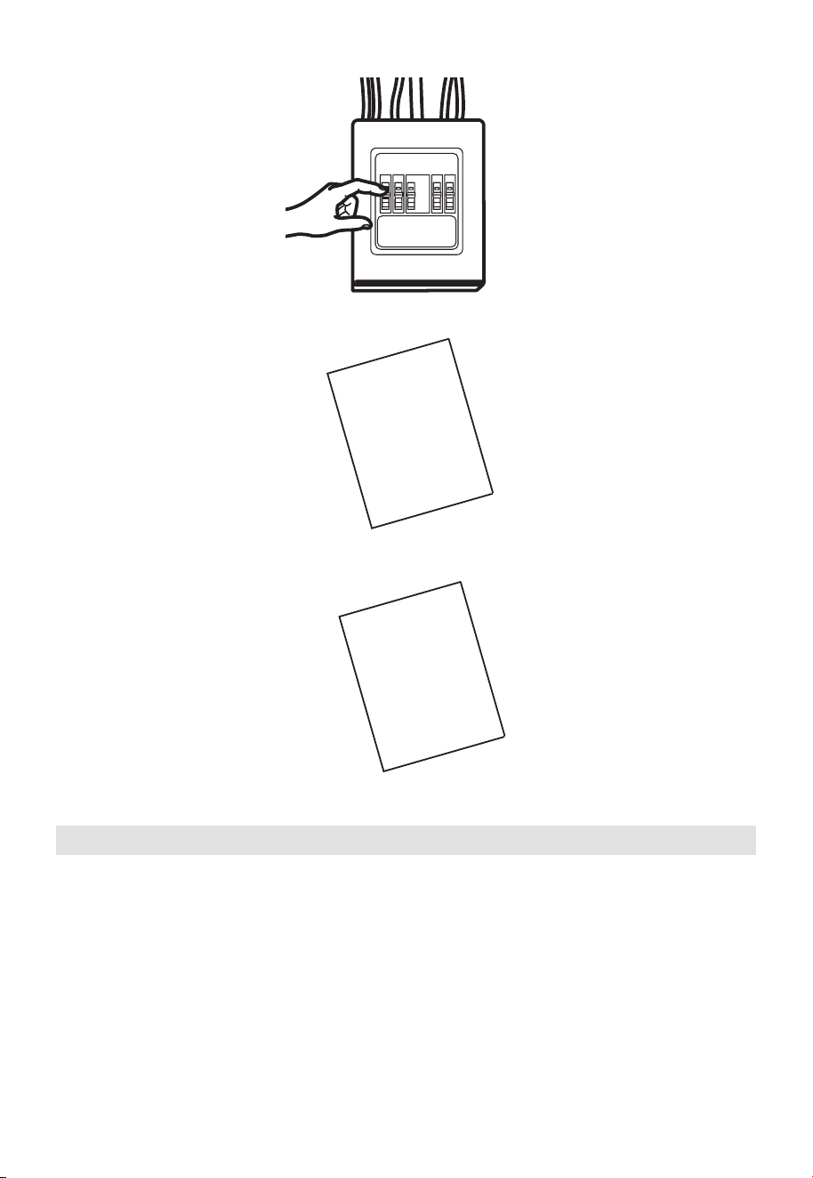
5. Replace house fuse or turn breaker back on.
6. Read the User Manual.
7. KEEP USER MANUAL FOR THE LOCAL INSPECTOR’S USE.
USER
MANUAL
USER
MANUAL
Operational Check
1. Make sure the unit has been installed according to these instructions.
2. Remove all packing materials from the oven.
3. Replace house fuse or turn circuit breaker back on.
4. Plug power cord into receptacle .
5. Read operating instructions before testing the product.
6. Turn on the exhaust fan at Turbo speed and confirm it is operating by using a tissue (it
will stick to the filter).
7. Confirm the outdoor ex-haust flapper has opened.
8. Set the microwave oven for 1 minute and confirm the oven is operat-ing normally using
a cup of water.
9. Keep these installation instruction for the local electrical inspector’s use.
EN-50
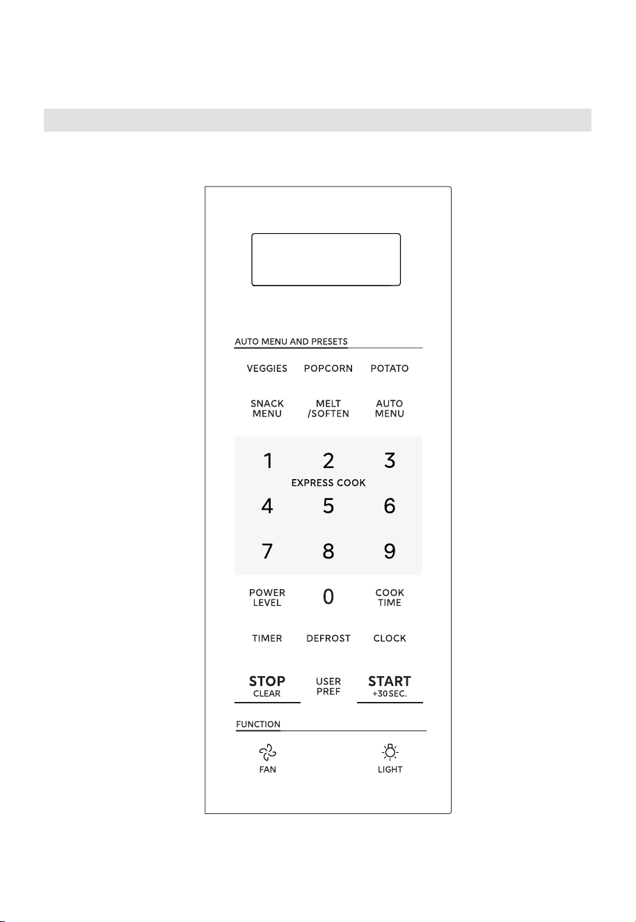
OPERATION INSTRUCTIONS
Control Panel
EN-51
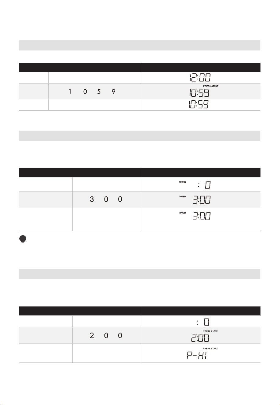
Setting The Clock
• Suppose you want to enter the correct time of day 10:59.
TOUCH DISPLAY SHOWS
:
1. CLOCK
2.
3.
CLOCK or START +30SEC.
Setting The Timer
Your microwave oven can be used as a kitchen timer. You can set up to 99 minutes , 99
seconds. The kitchen timer can be used while the microwave oven is running.
• Suppose you want to set for three minutes.
TOUCH DISPLAY SHOWS
:
1. TIMER
2.
3. TIMER
Time counting down
NOTE:
There are not any other programs during the kitchen timer.
Microwave
Your Over the Range Microwave Oven can be programmed for 99 minutes 99 seconds
(99 :99). Always enter the seconds after the minutes, even if they are both zeros.
• Suppose you want to cook for 2 minutes at 90% power
TOUCH DISPLAY SHOWS
:
1. COOK TIME
2.
3.
POWER LEVEL X1
EN-52
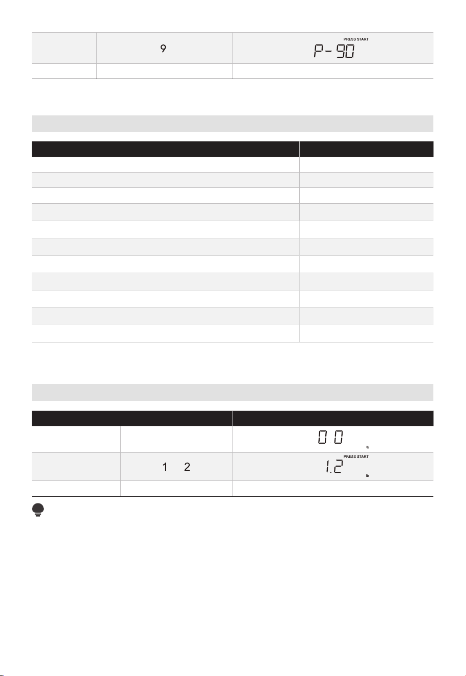
4.
5. Time counting down
Power Chart
POWER LEVEL DISPLAY
100% P-HI
90% P-90
80% P-80
70% P-70
60% P-60
50% P-50
40% P-40
30% P-30
20% P-20
10% P-10
0% P-0
Weight Defrost
TOUCH DISPLAY SHOWS
:
1.
2.
3. Time counting down
NOTE:
The weight amount must be a valid entry for this feature to start. A valid weight entry is 0.1
to 6.0 Ibs.
DEFROST X1
EN-53
START +30SEC.
START +30SEC.
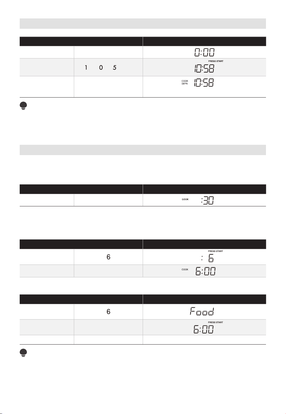
Time Defrost
TOUCH DISPLAY SHOWS
:
1.
2.
8
3.
Time counting down
NOTE:
The buzzer will sound to remind you of turning over the food when half of the time has
passed on.
Speed Cooking
This is a time-saving pad. It is a simplified feature that lets you quickly set and start
microwave cooking at 100% power.
TOUCH DISPLAY SHOWS
:
1.
Press number pads "1-6" to start cooking with corresponding time for 100% power level
directly. For example, cooking with 6 minutes for 100% power level.
TOUCH DISPLAY SHOWS
:
1.
2. After 2 seconds
The oven door should be open d and closed in 5 minutes before the speedy cooking,
operating as below.
TOUCH DISPLAY SHOWS
:
1.
2. open the door
3. Time counting down (Close the door)
NOTE:
"Food" will be displayed if the number keys 1 to 6 or " " key is not
selected within 5 minutes of placing food in the oven. You must open then close the
door again to clear "Food" from the display. And then press ?? " " to
y
e
DEFROST X2
.
1. Using add 30 seconds:
2. Using number pads for "1-6":
EN-54
otherwise,
START +30SEC.
START +30SEC.
START +30SEC.
START +30SEC.
strart cooking.
START +30SEC.
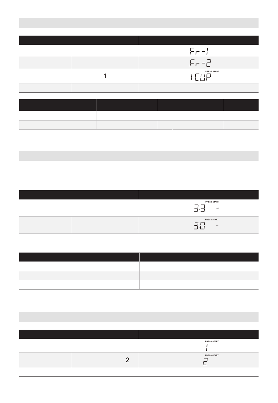
Veggies
TOUCH DISPLAY SHOWS
:
1. VEGGIES X1
Time counting down
PRESS VEGGIES PAD
FOOD AMOUNT
X1
Fresh Vegetable 1 - 4 cups
X2
Frozen Vegetable 1 - 4 cups
Popcorn
Press “POPCORN” key and LED displays 3.3 oz. Press “POPCORN” repeatedly to choose
• Suppose you want to cook 3.0 oz. popcorn.
TOUCH DISPLAY SHOWS
:
1.
2. POPCORN X1
3. Time counting down
PRESS POPCORN PAD
AMOUNT
X1 3.3 oz
X2 3.0 oz
X3 1.75 oz
Potato
TOUCH DISPLAY SHOWS
:
1. POTATO X1
2. POTATO X1 or
3. Time counting down
3.
4.
the desired weight.
VEGGIES X1
2.
POPCORN X1
EN-55
START +30SEC.
START +30SEC.
START +30SEC.
OR NUMDER KEYS
NUMDER KEYS
1, 2, 3, 4
1, 2, 3, 4
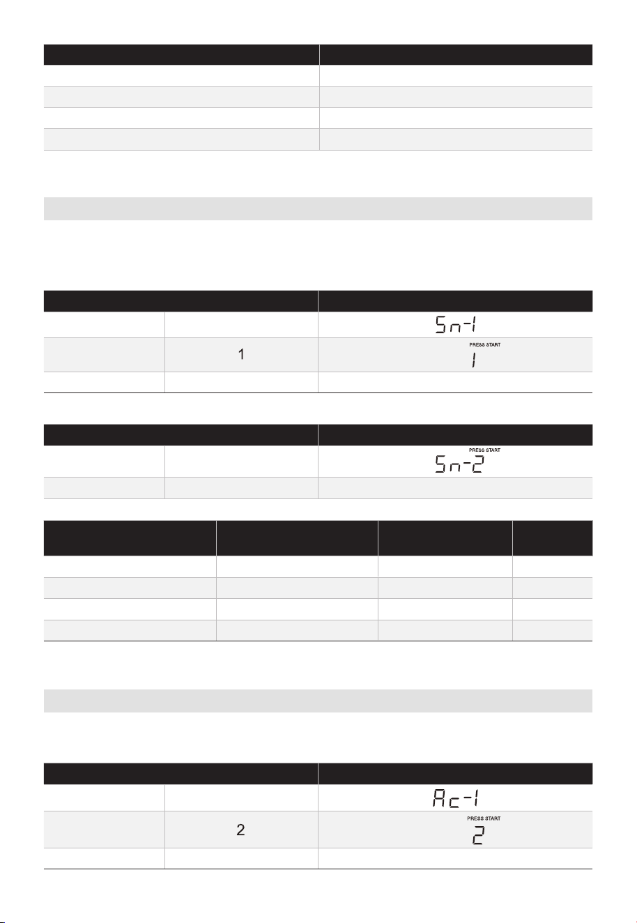
PRESS POTATO PAD OR NUMDER KEYS AMOUNT
X1 1
X2 2
X3 3
X4 4
Snack Menus
There are 4 options (Hot dogs,?? Frozen Kids Meal, Meal In A Cup, Soup) under the snack
menu.
1. Hot dogs or Soup
TOUCH DISPLAY SHOWS
:
1. SNACK MENUS X1
2.
3. Time counting down
2. Frozen Kids Meal
TOUCH DISPLAY SHOWS
:
1.
2. Time counting down
PRESS SNACK MENUS
PAD
FOOD AMOUNT
X1 Hot Dogs 1 - 6 pieces
X2 Frozen Kids Meal 8.8 oz
X3 Meal in a cup 2.39 oz
X4 Soup 1 - 2 cups
Auto Menu
There are 5 options (Bacon, Dinner Plate, Rice, Frozen breakfast, Frozen Pizza) under the
auto cook.
TOUCH DISPLAY SHOWS
:
1. AUTO MENU X1
2.
3. Time counting down
SNACK MENUS X2
EN-56
START +30SEC.
START +30SEC.
START +30SEC.
NUMDER KEYS
1, 2, 3, 4??,5,6
1, 2,
-
-
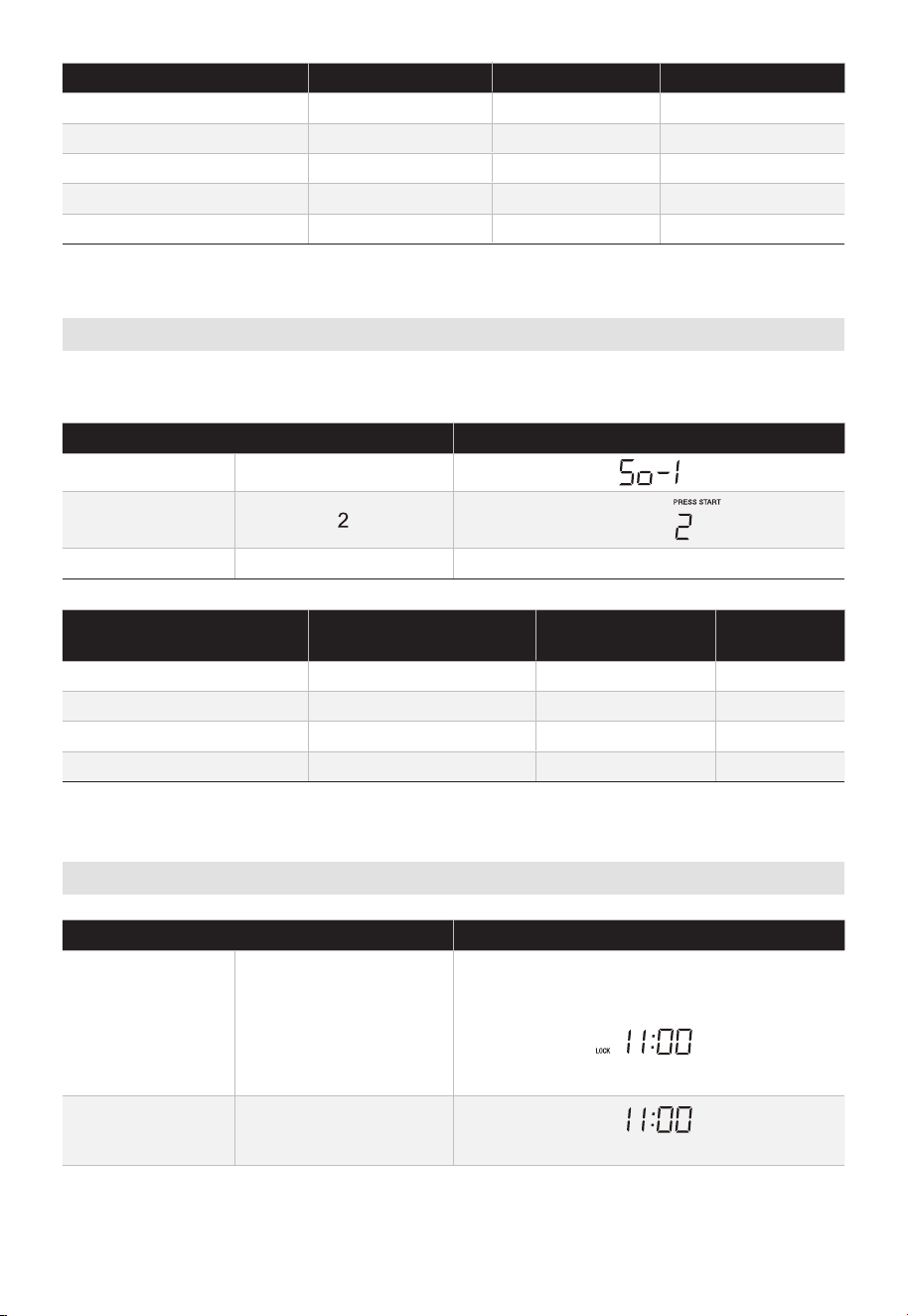
PRESS AUTO MENU FOOD AMOUNT
X1 Bacon 1-3 Slices
X2 Dinner Plate 1-2 Plates
X3 Rice 1-2 Cups
X4 Frozen breakfast 8/12 oz
X5 Frozen Pizza 6/8/12 oz
Melt/Soften
The oven uses low power to melt and soften items. See the following table.
• Suppose you want to melt 2 sticks of Butter.
TOUCH DISPLAY SHOWS
:
1. MELT/SOFTEN X 1
2.
3. Time counting down
PRESS MELT/SOFTEN
PAD
FOOD AMOUNT
X1 Melt Butter 1/2 stick
X2 Melt Chocolate 2/4/8 oz
X3 Soften Ice Cream Pint/1.5Quart
X4 Soften Cream Cheese 3/8 oz
Child Lock
TOUCH DISPLAY SHOWS
:
1.
STOP/
CLEAR
(for 3 seconds)
(if clock is set)
2.
STOP/
CLEAR
(for 3 seconds)
OR
(if clock is set)
LOCK
EN-57
NUMDER KEYS
1, 2, 3,
1, 2,
1, 2,
1, 2,
1, 2, 3,
START +30SEC.
1, 2, 3,
1, 2,
1, 2,
1, 2,
NUMDER KEYS
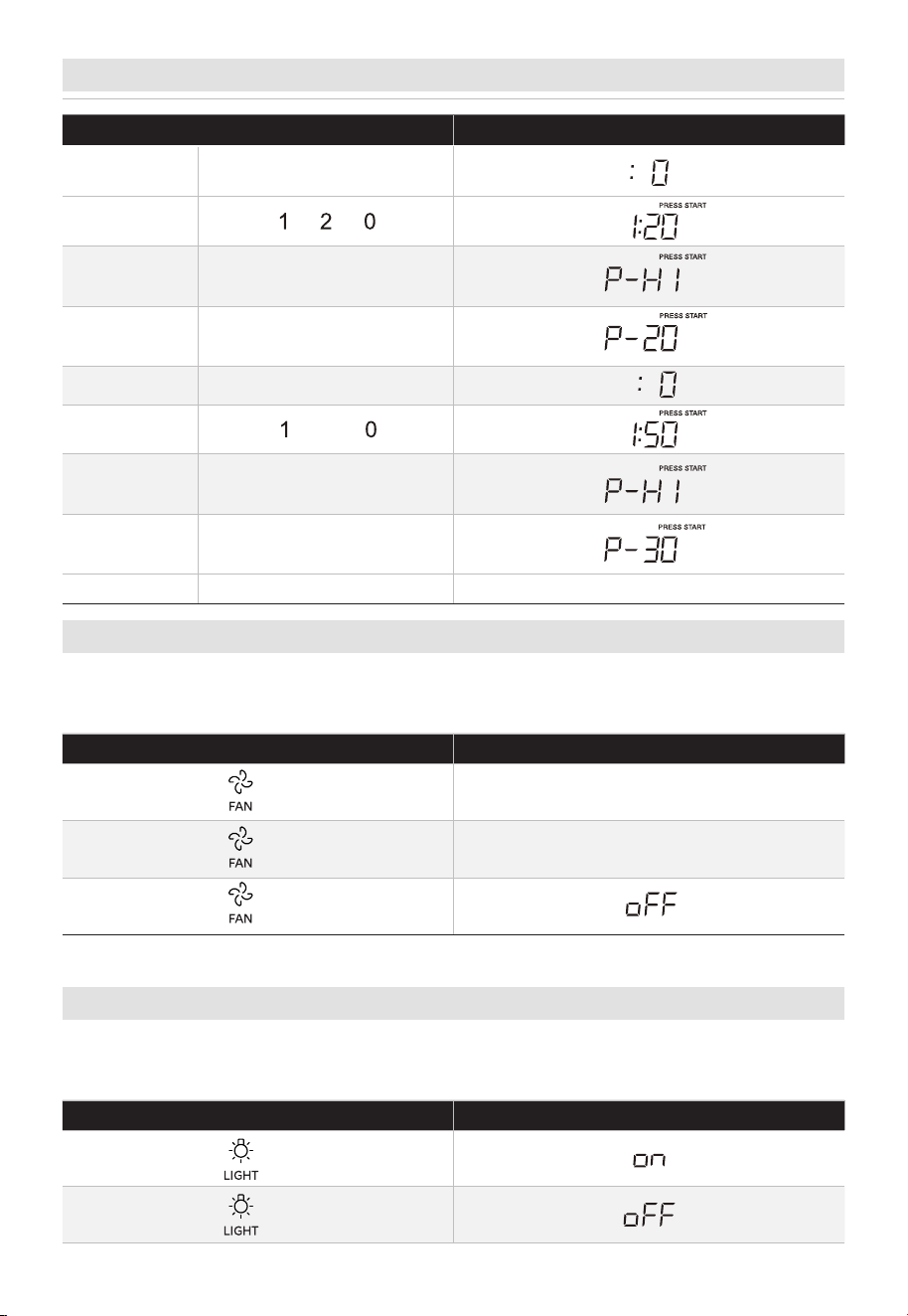
Stage Cook
TOUCH DISPLAY SHOWS
:
1.
2.
3.
4.
5.
5
6.
7.
3
Time counting down
Vent Fan
The pad controls the 2-speed vent fan. If the vent fan is OFF, the first touch of the FAN pad
TOUCH DISPLAY SHOWS
:
X1 HI
X2 Lo
X3\
Light
The pad controls the 2-states light. If the light is OFF, the first touch of the light pad will
turn the light on, second touch OFF.
TOUCH DISPLAY SHOWS
:
X1
X2
8.
\CO\OK TIME
will turn the fan on HIGH, second touch LOW and third touch OFF.
POWER LEVEL X8 or
POWER LEVEL X1
POWER LEVEL X1
POWER LEVEL X7 or
EN-58
\CO\OK TIME
9.
START +30SEC.
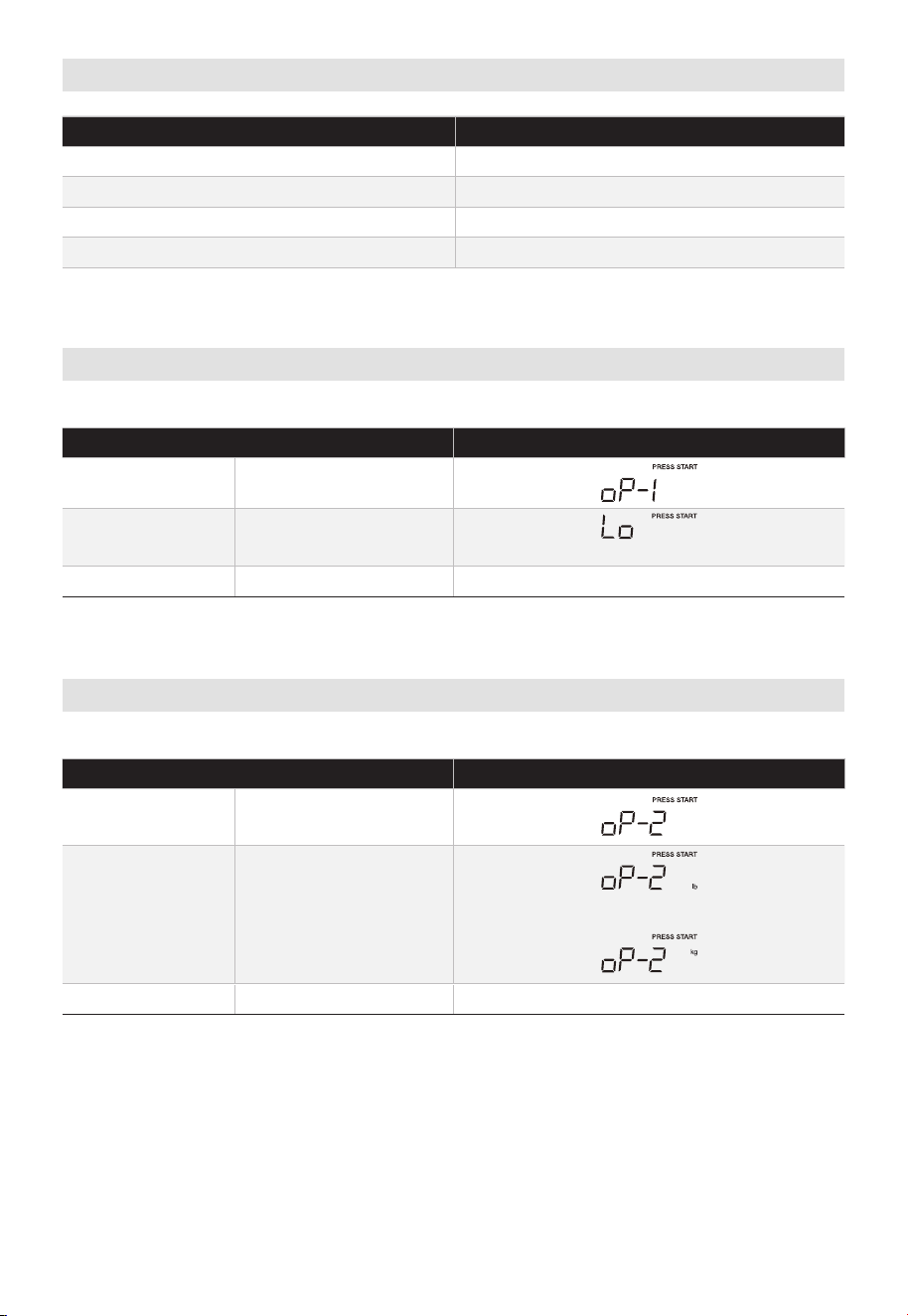
User Pref
KEY SETTING
USER PREF X1 Volume / / /Off
USER PREF X2 Weight lb/kg
USER PREF X3 Clock Display On/Off
USER PREF X4 Demo Mode
Volume
In standby mode:
TOUCH DISPLAY SHOWS
:
1.
USER PREF X1
2.
(Lo, nor, HI, oFF will display in order)
3.
Weight (lb/kg)
In standby mode:
TOUCH DISPLAY SHOWS
:
1. USER PREF X2
2.
or
3.
Lo Nor Hi
EN-59
START +30SEC.
START +30SEC.
START +30SEC.
START +30SEC.
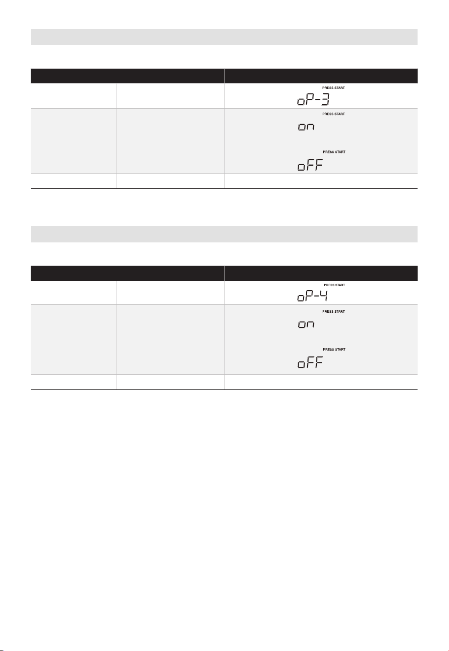
Clock Display O/On
In standby mode:
TOUCH DISPLAY SHOWS
:
1. USER PREF X3
2.
3.
Demo Mode
In standby mode:
TOUCH DISPLAY SHOWS
:
1. USER PREF X4
2.
3.
or
or
EN-60
START +30SEC.
START +30SEC.
START +30SEC.
START +30SEC.

TROUBLESHOOTING
Check your problem by using the chart below and try the solutions for each problem. If
the microwave oven still does not work properly, contact the nearest authorized service
center.
TROUBLE POSSIBLE CAUSE POSSIBLE REMEDY
Oven will not start
• Electrical cord for oven is
not plugged in.
• Door is open.
• Wrong operation is set.
• Plug into the outlet.
• Close the door and try
again.
• Check instructions.
Arcing or sparking
• Materials to be avoided
in microwave oven were
used.
• The oven is operated
when empty.
• Spilled food remains in
the cavity.
• Use microwave-safe
cookware only.
• Do not operate with oven
empty.
• Clean cavity with wet
towel.
Unevenly cooked foods
• Materials to be avoided
in microwave oven were
used.
• Food is not defrosted
completely.
• Cooking time, power
level is not suitable.
• Food is not turned or
stirred.
• Use microwave-safe
cookware only.
• Completely defrost food.
• Use correct cooking time,
power level.
• Turn or stir food.
Overcooked foods
• Cooking time, power
level is not suitable.
• Use correct cooking time,
power level.
Undercooked foods
• Materials to be avoided
in microwave oven were
used.
• Food is not defrosted
completely.
• Oven
ventilation ports
are restricted.
• Cooking time, power
level is not suitable.
• Use microwave-safe
cookware only.
• Completely defrost food.
• Check to see that oven
venti- lation ports are
not restricted.
• Use correct cooking time,
power level.
Improper defrosting
• Materials to be avoided
in microwave oven were
used.
• Cooking time, power
level is not suitable.
• Food is not turned or
stirred.
• Use microwave-safe
cookware only.
• Use correct cooking time,
power level.
• Turn or stir food.
EN-61

logo, word marks, trade name, trade dress and all versions thereof are
trademarks, copyrights and other intellectual property rights, and all goodwill derived
from using any part of an Midea trademark. Use of Midea trademark for commercial
purposes without the prior written consent of Midea may constitute trademark
infringement or unfair competition in violation of relevant laws.
This manual is created by Midea and Midea reserves all copyrights thereof. No entity or
individual may use, duplicate, modify, distribute in whole or in part this manual, or
bundle or sell with other products without the prior written consent of Midea.
All the described functions and instructions were up to date at the time of printing this
manual. However, the actual product may vary due to improved functions and designs.
TRADEMARKS, COPYRIGHTS
AND LEGAL STATEMENT
TRADEMARKS, COPYRIGHTS AND LEGAL STATEMENT
valuable assets of Midea Group and/or its affiliates ("Midea"). to which Midea owns
EN-62

DATA PROTECTION NOTICE
For the provision of the services agreed with the customer,
we agree to comply without restriction with all stipulations of applicable data protection
law, in line with agreed countries within which services to the customer will be delivered.
Generally, our data processing is to fulfil our obligation under contract with you and for
product safety reasons, to safeguard your rights in connection with warranty and
product registration questions. In some cases, but only if appropriate data protection is
ensured, personal data might be transferred to recipients located outside of the
European Economic Area.
Further information are provided on request. You can contact our Data Protection
Officer via [email protected]. To exercise your rights such as right to object your
personal date being processed for direct marketing purposes, please contact us via
[email protected]. To find further information, please follow the QR Code.
DATA PROTECTION NOTICE
EN-63

This warranty is provided to the delivery at retail (the “Purchaser” or “you”)
by Midea America Corp. (“Midea” or “we”), which warrants all parts of this Product, as
described below. Midea warrants this Product to the Purchaser for personal, family or
household use. This warranty covers performance and quality issues in materials and
workmanship that appear under normal use and maintenance appearing within one year
from the date of purchase. This warranty gives you specific rights, and you may also
have other rights that vary from state to state. The date of delivery establishes the
warranty period, should service be required.
WARRANTY LIMITATIONS
This warranty is given only to the delivery at retail in either the United States
or Canada and may not be transferred to any subsequent buyer. This warranty does
not apply to purchasers of our products for use or resale in a business; a separate
commercial warranty may protect those purchasers.
This warranty does not cover any Product failure caused by:
a. Abuse, damage or use of the Product in violation of the Product instructions.
b. Modification to any Product or part.
c. Failure to maintain the Product or part as described in accordance with the Product
instructions.
d. Faulty installation or application.
e. Use of parts or accessories not compatible with this Product.
f. Floods, fires, winds, lightning, accidents, corrosive atmosphere
, or other conditions
beyond Midea’s control.
g. Interruption in electrical service or inadequate electrical service.
h. Replacement of fuses and replacement or resetting of circuit breakers.
i. Frozen or broken water pipes, water damage, moisture intrusion, mold or other
biological growth.
j. The use, combination or linking of the Product to other products, processes or
materials not provided by Midea.
WARRANTY REMEDY
If any quality or performance issue covered by this warranty is discovered during the
warranty period, we will, at our option, repair or replace any such Product. This warranty
is limited to Product repair or replacement by an authorized Midea servicer or dealer
and does not cover any shipping cost, labor cost, customs duties, inland logistics cost, or
cost of service, including any diagnostics, removal, transportation, or reinstallation costs.
If we ask, you must return the Product to us.
WARRANTY DISCLAIMER; EXCLUSION OF DAMAGES
This is the only express warranty to consumers that we oer on our Products. ANY
IMPLIED WARRANTIES BY MIDEA, INCLUDING BUT NOT LIMITED TO WARRANTIES OF
MERCHANTABILITY AND FITNESS FOR PARTICULAR PURPOSE, ARE LIMITED TO THE
DURATION OF THIS EXPRESS WARRANTY. Some states and provinces do not allow the
exclusion of express warranties and/or limitations on how long an implied warranty lasts,
so the above exclusion and/or limitation may not apply to you.
THE REMEDY DESCRIBED ABOVE IS THE ONLY ONE THAT WE WILL PROVIDE, EITHER
UNDER THIS WARRANTY OR UNDER ANY WARRANTY ARISING BY OPERATION OF
LAW. WE WILL NOT BE RESPONSIBLE FOR ANY CONSEQUENTIAL OR INCIDENTAL
DAMAGES ARISING FROM THE BREACH OF THIS WARRANTY OR ANY OTHER
WARRANTY, WHETHER EXPRESS OR IMPLIED, NEGLIGENCE OR OTHER TORT, OR ON
EN-64
1 YEAR LIMITED WARRANTY

ANY STRICT LIABILITY THEORY, INCLUDING BUT NOT LIMITED TO LOST PROFITS.
Some states do not allow the exclusion or limitation of incidental or consequential
damages, so the above exclusion may not apply to you.
WARRANTY CLAIMS PROCESS
For more information or to make a warranty claim, please visit:
https://www.midea.com/Canada/support
Or contact us at:
Telephone: 1-888-365-2230
Email: CanadaSupport@midea.com
You must have Your bill of sale, delivery slip, or appropriate proof of purchase to submit
a warranty claim. The date of purchase establishes the warranty period, should service
be required.
DISPUTE RESOLUTION
ARBITRATION CLAUSE. IMPORTANT. PLEASE REVIEW THIS ARBITRATION CLAUSE. IT
AFFECTS YOUR LEGAL RIGHTS.
a. Parties: This arbitration clause (this “Arbitration Clause”) affects your rights against
Midea and any of its affiliates or employees or agents, successors, or assigns, all of
whom together are referred to below as “we” or “us” for ease of reference.
b. ARBITRATION REQUIREMENT: EXCEPT AS STATED BELOW, ANY DISPUTE
BETWEEN YOU AND ANY OF US SHALL BE DECIDED BY NEUTRAL, BINDING
ARBITRATION RATHER THAN IN COURT OR BY JURY TRIAL. “Dispute” will be given
the broadest possible meaning allowable by law. It includes any dispute, claim, or
controversy arising from or relating to your purchase of this Product, any warranty
upon the Product, or the Product’s condition. It also includes determination of the
scope or applicability of this Arbitration Clause. The arbitration requirement applies
to claims in contract and tort, pursuant to statute, or otherwise.
c. CLASS-ARBITRATION WAIVER: ARBITRATION IS HANDLED ON AN INDIVIDUAL
BASIS. IF A DISPUTE IS ARBITRATED, YOU AND WE EXPRESSLY WAIVE ANY
RIGHT TO PARTICIPATE AS A CLASS REPRESENTATIVE OR CLASS MEMBER ON
ANY CLASS CLAIM YOU MAY HAVE AGAINST US OR WE AGAINST YOU, OR AS A
PRIVATE ATTORNEY GENERAL OR IN ANY OTHER REPRESENTATIVE CAPACITY,
TO THE MAXIMUM EXTENT PERMITTED BY LAW. YOU AND WE ALSO WAIVE
ANY RIGHT TO CLASS ARBITRATION OR ANY CONSOLIDATION OF INDIVIDUAL
ARBITRATIONS.
d. Discovery and Other Rights: Discovery and rights to appeal in arbitration are
generally more limited than in a lawsuit. This applies to both you and us. Other rights
that you or we would have in court may not be available in arbitration. Please read
this Arbitration Clause and consult the rules of the arbitration organizations listed
below for more information.
e. SMALL CLAIMS COURT OPTION: YOU MAY CHOOSE TO LITIGATE ANY DISPUTE
BETWEEN YOU AND ANY OF US IN SMALL CLAIMS COURT, RATHER THAN IN
ARBITRATION, IF THE DISPUTE MEETS ALL REQUIREMENTS TO BE HEARD IN
SMALL CLAIMS COURT.
f. Governing Law: For residents of the United States, the procedures and effect
of the arbitration will be governed by the Federal Arbitration Act (9 U.S.C. § 1 et
seq.) rather than by state law concerning arbitration. For residents of Canada,
the procedures and effect of the arbitration will be governed by the applicable
arbitration law of the province in which you purchased your Product. The law
governing your substantive warranty rights and other claims will be the law of the
state or province in which you purchased your Product. Any court having jurisdiction
may enter judgment on the arbitration award.
g. Rules of the Arbitration: If the amount in controversy is less than $250,000, the
EN-65

arbitration will be decided by a single arbitrator. If the amount in controversy is
greater than or equal to $250,000, the arbitration will be decided by a panel of three
arbitrators. The arbitrator(s) will be chosen pursuant to the rules of the administering
arbitration organization. United States residents may choose JAMS (1920 Main
Street, Ste. 300, Irvine, CA 92614, www.jamsadr.com), or, subject to our approval,
any other arbitration organization. In addition, Canadian residents may choose the
ADR Institute of Canada (234 Eglinton Ave. East, Suite 405, Toronto, Ontario, M4P
1K5, www.amic.org). These organizations’ rules can be obtained by contacting the
organization or visiting its website. If the chosen arbitration organization’s rules
conflict with this Arbitration Clause, the provisions of this Arbitration Clause control.
The award of the arbitrator(s) shall be final and binding on all parties.
h. Location of the Arbitration Hearing: Unless applicable law provides otherwise, the
arbitration hearing for United States residents will be conducted in the federal
judicial district in which you reside (in your hometown area) or, for Canadian
residents, in the province in which you reside, and, if you choose, will be in-person.
i. Costs of the Arbitration: Each party is responsible for its own attorney, expert, and
other costs and fees unless applicable law requires otherwise. Notwithstanding
the preceding sentence, and unless applicable law requires otherwise, if you are
a consumer under the JAMS rules or the rules of another agreed upon arbitration
administrator, Midea will pay or reimburse you for all reasonable fees or costs
to the extent required by law or the applicable arbitration administrator’s rules.
Whether or not required by law or such rules, if you prevail at arbitration on any
claim against Midea, Midea will reimburse you for any reasonable fees paid to the
arbitration administrator in connection with the arbitration proceedings. Under
no circumstances will Midea seek from you payment or reimbursement of any
reasonable fees that Midea incurs in connection with the arbitration. If you are
required to advance any fees or costs to JAMS or other agreed upon arbitration
administrator, but you ask Midea to do so in your stead, Midea will consider and
respond to your request.
j. Survival and Enforceability of this Arbitration Clause: This Arbitration Clause shall
survive the expiration or termination, or any transfer, of the warranty on your
Product. If any part of this Arbitration Clause, except waivers of class-action rights,
is found to be unenforceable for any reason, the remainder of this clause and the
warranty shall remain enforceable. If, in a case in which class-action allegations
have been made, the waiver of class-action rights under this warranty is found to
be unenforceable with respect to any part of the dispute, the parts of the dispute
as to which the waiver of class-action rights have been found unenforceable will be
severed and will proceed in court without reference or application of this Arbitration
Clause. Any remaining parts will proceed in arbitration.
QUEBEC RESIDENTS
The arbitration provisions of this warranty shall not apply to residents of Quebec.
EN-66


MANUEL
D'UTILISATION
MMO17S12ASTC
Avertissements : Avant d'utiliser ce produit, veuillez lire attentivement ce manuel et le conserver pour
référence ultérieure. La conception et les spécifications sont sujettes à changement sans préavis pour
l'amélioration du produit. Consultez votre revendeur ou votre fabricant pour plus de détails.
Le schéma ci-dessus est juste à titre de référence. Veuillez prendre l'apparence du produit réel comme
standard.
Prolongation gratuite de
3 mois de la période de
garantie limitée d'origine !*
Envoyez simplement une
photo de votre preuve
d'achat à :
1-844-224-1614
*L'extension de garantie est pour les trois
mois suivant immédiatement la fin de la
période de garantie initiale du produit. Les
particuliers n’ont pas besoin d’enregistrer le
produit pour bénéficier de tous les droits et
recours des propriétaires enregistrés dans le
cadre de la garantie limitée d’origine.
FOUR À MICRO-ONDES DOMESTIQUE

FR-01
LETTRE DE REMERCIEMENT -----------------------------------FR-01
CONSIGNES DE SÉCURITÉ --------------------------------------FR-02
CARACTÉRISTIQUES --------------------------------------------FR-12
APERÇU DU PRODUIT -------------------------------------------FR-13
INSTALLATION DU PRODUIT ----------------------------------FR-14
CONSIGNES D'UTILISATION ------------------------------------FR-53
DÉPANNAGE ------------------------------------------------------FR-64
MARQUES, DROITS D'AUTEUR ET DÉCLARATION
LÉGALE ------------------------------------------------------------FR-65
AVIS DE PROTECTION DES DONNÉES -----------------------FR-66
GARANTIE LIMITÉE D'UN AN ----------------------------------FR-67
SOMMAIRE
LETTRE DE REMERCIEMENT
Merci d'avoir choisi Midea ! Avant d'utiliser votre nouveau produit Midea, veuillez
lire attentivement ce manuel pour vous assurer que vous savez comment utiliser les
fonctionnalités et les fonctions offertes par votre nouvel appareil de manière sûre.
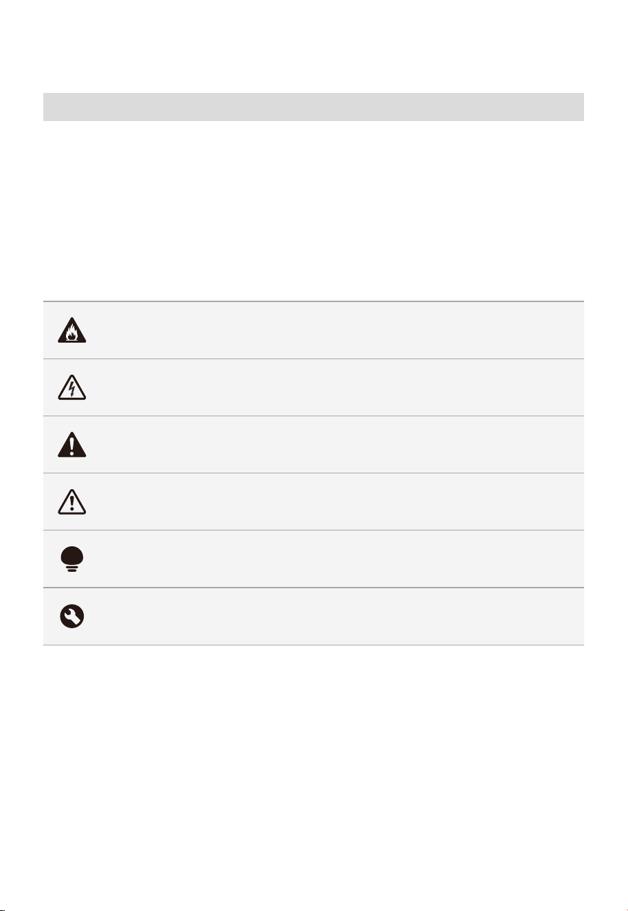
FR-02
CONSIGNES DE SÉCURITÉ
Utilisation prévue
Les consignes de sécurité suivantes visent à prévenir les risques imprévus ou les
dommages causés par un fonctionnement dangereux ou incorrect de l'appareil. Veuillez
vérifier l'emballage et l'appareil à l'arrivée pour vous assurer que tout est intact et
assurer un fonctionnement en toute sécurité. Si vous constatez des dommages, veuillez
contacter le détaillant ou le revendeur. Veuillez noter que les modifications ou altérations
de l'appareil ne sont pas autorisées pour des raisons de sécurité. Une utilisation
involontaire peut entraîner des dangers et l'annulation des demandes de garantie.
Explication des symboles
Danger
Ce symbole indique qu'il existe des dangers pour la vie et la santé des personnes
en raison des gaz extrêmement inflammables.
Avertissement relatif à la tension électrique
Ce symbole indique qu'il existe un danger pour la vie et la santé des personnes en
raison de la tension.
Avertissement
Le mot de signalisation indique un danger avec un niveau de risque moyen qui, s'il
n'est pas évité, peut entraîner la mort ou des blessures graves.
Mise en garde
Le mot de signalisation indique un danger avec un faible degré de risque qui, s'il
n'est pas évité, peut entraîner des blessures mineures ou modérées.
Attention
Ce symbole indique une information importante (par exemple, un dommage
matériel), mais pas un danger.
Respectez les instructions
Ce symbole indique qu'un technicien d'entretien ne doit utiliser et entretenir cet
appareil que conformément au consignes d'utilisation.
Lisez attentivement ces consignes d'utilisation avant d'utiliser/de mettre en service
l'unité et conservez-les à proximité immédiate du site d'installation ou de l'unité pour une
utilisation ultérieure !

FR-03
PRÉCAUTIONS POUR ÉVITER
L’EXPOSITION POSSIBLE À
UNE ÉNERGIE MICRO-ONDES
EXCESSIVE
a. N'essayez pas de faire fonctionner ce four avec
la porte ouverte, car cela peut entraîner une
exposition nocive à l'énergie des microondes.
Il est important de ne pas annuler ou altérer les
verrouillages de sécurité.
b. Ne pas placer un objet entre la face avant et la
porte, ou laisser de la saleté ou des résidus de
nettoyage s’accumuler sur les surfaces du joint.
c. N’utilisez pas le four s’il est endommagé. Il est
particulièrement important que la porte du four se
ferme correctement et qu’il n’y ait aucun dommage
au :
-
PORTE (courbée)
-
CHARNIÈRES ET LOQUETS (cassés ou desserrés)
-
JOINTS DE PORTE ET SURFACE D'ÉTANCHÉITÉ
d. Le four ne doit pas être réglé ou réparé par qui que
ce soit à l’exception d’un personnel de dépannage
qualifié.

FR-04
CONSIGNES DE SÉCURITÉ
IMPORTANTES
Lorsque vous utilisez des appareils électriques, vous
devez respecter des précautions de base en matière de
sécurité, y compris (mais sans s’y limiter) les suivantes :
AVERTISSEMENT
Pour réduire les risques de brûlures, d’électrocution,
d’incendie, de blessures ou d’exposition à une énergie
micro-ondes excessive :
• Lisez toutes les consignes avant d'utiliser l'appareil.
• Lisez et suivez les consignes spécifiques :
«PRÉCAUTIONS À PRENDRE POUR ÉVITER UNE
EXPOSITION POSSIBLE À UNE ÉNERGIE EXCESSIVE
DES MICRO-ONDES» se trouve à la page 03.
• Ce four doit être mis à la terre. Branchez uniquement
à une prise correctement mise à la terre. Voir
«CONSIGNES DE MISE À LA TERRE» à la page 07.
• Installez ou placez ce four uniquement
conformément aux instructions d’installation
fournies.
• Certains produits tels que les œufs entiers et les
récipients scellés - par exemple, les bocaux en verre
fermés - peuvent exploser et ne doivent pas être
chauffés dans le four.
• Utilisez cet appareil uniquement pour l’usage
auquel il est destiné, tel que décrit dans ce manuel.
N’utilisez pas de produits chimiques ou de vapeurs
corrosifs dans cet appareil. Ce four est spécialement
conçu pour chauffer, cuire ou sécher des aliments.
Cet appareil n’est pas conçu pour une utilisation
industrielle ou en laboratoire.

FR-05
• LES CONTENUS CHAUDS PEUVENT CAUSER DE
GRAVES BRÛLURES. NE PERMETTEZ PAS AUX
ENFANTS D'UTILISER LE MICRO-ONDES. Soyez
prudent lorsque vous retirez des articles chauds.
• N'utilisez pas ce four si le cordon ou la fiche est
endommagée, s'il ne fonctionne pas correctement, s'il
est endommagé ou s'il est tombé.
• Cet appareil ne doit être entretenu que par un
personnel de service qualifié. Contactez le centre de
service agréé le plus proche pour examen, réparation
ou réglage.
• Ne couvrez ni bloquez les ouvertures de l’appareil.
• Il ne faut pas mettre cet appareil à l'extérieur.
N’utilisez pas ce four près de l’eau, par exemple près
d’un évier de cuisine, dans un sous-sol humide, près
d’une piscine ou dans des endroits similaires.
• N’immergez pas le cordon ou la fiche dans l’eau.
• Éloigner le cordon de toute surface chauffée.
• Ne laissez pas le cordon pendre par le bord de la
table ou du comptoir.
• Lors du nettoyage des surfaces de la porte et du
four qui se rejoignent lors de la fermeture, utilisez
uniquement des savons ou détergents doux non
abrasifs appliqués avec une éponge d’un chiffon
doux.
• Pour réduire le risque d’incendie dans la cavité du
four :
-
Ne faites pas trop cuire les aliments. Surveillez
attentivement l'appareil si vous avez placé un
objet en papier, plastique ou autre matériau
combustible dans la cavité pour faciliter la cuisson.
-
Retirez les attaches métalliques des sacs en papier
ou en plastique avant de les placer dans le four.

FR-06
-
Si le matériau à l'intérieur du four s'enflamme,
gardez la porte du four fermée, éteignez le four et
débranchez le cordon d'alimentation, ou coupez
l'alimentation au niveau du fusible ou du panneau
du disjoncteur.
-
N’utilisez pas la cavité à des fins de stockage. Ne
laissez pas de produits en papier, d’ustensiles de
cuisine ou de nourriture dans la cavité lorsqu’ils ne
sont pas utilisés.
• Les liquides, tels que l’eau, le café ou le thé, peuvent
surchauffer au-delà du point d’ébullition sans avoir
l’air de bouillir. Un bouillonnement ou une ébullition
visible lorsque le récipient est retiré du four à micro-
ondes n’est pas toujours présent.
CELA POURRAIT ENTRAÎNER SOUDAINEMENT UN
LIQUIDE TRÈS CHAUD BOUILLANT LORSQUE LE
RÉCIPIENT EST DÉRANGÉ OU QU'UN USTENSILE EST
INSÉRÉ DANS LE LIQUIDE. Pour réduire le risque de
blessures aux personnes :
-
Ne surchauffez pas le liquide.
-
Remuez le liquide avant et à mi-cuisson.
-
N’utilisez pas de récipients à parois droites à col
étroit.
-
Après chauffage, laissez le récipient reposer dans
le four à micro-ondes pendant un court instant
avant de retirer le récipient.
-
Soyez extrêmement prudent lorsque vous insérez
une cuillère ou un autre ustensile dans le récipient.
• Les aliments et les ustensiles métalliques trop grands
ne doivent pas être introduits dans un four à micro-
ondes/grille-pain, car ils peuvent entraîner un risque
d'incendie ou d'électrocution.
• Ne nettoyez pas avec des tampons à récurer en
métal. Des pièces peuvent brûler les tampons et

FR-07
toucher les pièces électriques, entraînant un risque
de choc électrique.
• N'utilisez pas de produits en papier lorsque l'appareil
fonctionne en mode grille-pain.
• Ne rangez pas des objets autres que les accessoires
recommandés par le fabricant dans ce four lorsqu'il
n'est pas utilisé.
• Ne couvrez pas les grilles et toute autre partie du four
avec du papier d'aluminium. Le four peut surchauffer.
• Nettoyez fréquemment la hotte de ventilation - Ne
laissez pas la graisse s’accumuler sur la hotte ou le
filtre.
• Lorsque des aliments s’enflamment sous la hotte,
allumez le ventilateur.
• Faites attention lors du nettoyage du filtre de la
hotte. Les agents de nettoyage corrosifs, tels que la
soude, peuvent endommager le filtre.
• Il peut être utilisé avec des ustensiles de cuisson au
gaz et électriques.
CONSERVEZ CES CONSIGNES
INSTRUCTIONS DE MISE À LA
TERRE
Ce four doit être mis à la terre. En cas de court-circuit
électrique, la mise à la terre réduit le risque de décharge
électrique en fournissant un fil d'échappement pour le
courant électrique. Cet appareil est équipé d'un cordon
ayant un fil de mise à la terre avec une fiche de mise
à la terre. La fiche doit être branchée dans une prise
correctement installée et mise à la terre.

FR-08
AVERTISSEMENT
Une mauvaise utilisation de la mise à la terre peut
entraîner un risque d'électrocution. Consultez un
électricien ou un réparateur qualifié si les instructions
de mise à la terre ne sont pas complètement
comprises ou en cas de doute quant à la mise à la
terre de l’appareil. S’il est nécessaire d’utiliser une
rallonge, utilisez uniquement une rallonge à 3 fils
dotée d’une fiche de mise à la terre à 3 broches et des
prises à 3 positions qui acceptent la fiche de l’appareil.
La puissance nominale de la rallonge doit être égale
ou supérieure à la puissance électrique de l’appareil.
DANGER
Risque de décharge électrique
Toucher certains des composants internes peut causer
des blessures graves ou la mort. Ne démontez pas cet
appareil.
AVERTISSEMENT
Risque de décharge électrique
Une mauvaise utilisation de la mise à la terre peut
entraîner une décharge électrique. Ne branchez pas
une prise de courant tant que l'appareil n'est pas
correctement installé et mis à la terre.
• Un cordon d'alimentation court est fourni pour
réduire les risques de s'emmêler ou de trébucher sur
un cordon plus long.
• Des jeux de cordons plus longs ou des rallonges
sont disponibles et peuvent être utilisés si un soin
particulier est apporté à leur utilisation.

FR-09
• Si un long cordon ou une rallonge est utilisée :
-
La valeur nominale électrique marquée du cordon
ou de la rallonge doit être au moins aussi élevée
que la valeur nominale électrique de l'appareil.
-
La rallonge doit être un cordon à 3 fils de type
mise à la terre.
-
Le cordon le plus long doit être disposé de
sorte qu'il ne s'étende pas sur le comptoir ou le
dessus de table de façon à ce qu'il ne peut pas
être tiré par les enfants ou les faire trébucher
involontairement.
INTERFÉRENCE RADIO
• Le fonctionnement du four à micro-ondes peut
provoquer des interférences avec votre radio,
télévision ou équipement similaire.
• Lorsqu’il y a des interférences, elles peuvent être
réduites ou éliminées en prenant les mesures
suivantes :
-
Nettoyez la porte et les surfaces d'étanchéité du
four.
-
Réorientez l’antenne de réception de la radio ou
du téléviseur.
-
Déplacez le four à micro-ondes par rapport au
récepteur.
-
Éloignez le four à micro-ondes du récepteur.
-
Branchez le four à micro-ondes dans une prise
différente afin que le four à micro-ondes et le
récepteur soient sur des circuits de dérivation
différents.

FR-10
CET APPAREIL EST CONFORME
À LA PARTIE 18 DES RÈGLES DE
LA FCC.
USTENSILES
MISE EN GARDE
Risque de blessures
Des ustensiles bien fermés pourraient exploser. Les
récipients fermés doivent être ouverts et les sachets
en plastique doivent être percés avant la cuisson.
Voir les instructions sur « Matières que vous pouvez
utiliser dans un four à micro-ondes ou devez éviter de
mettre dans un four à micro-ondes. »
Il peut y avoir certains ustensiles non métalliques qui
ne sont pas sûrs à utiliser dans un four micro-ondes.
En cas de doute, vous pouvez tester l'appareil en
question en suivant la procédure ci-dessous.
Test d'ustensile:
• Remplissez un récipient adapté aux micro-ondes
avec 1 tasse d'eau froide (250 ml) avec l'ustensile en
question.
• Cuire à puissance maximale pendant 1 minute.
• Sentez attentivement l'ustensile. Si l'ustensile vide
est chaud, ne l'utilisez pas pour la cuisson au micro-
ondes.
• Ne dépassez 1 minute de cuisson.

FR-11
Matériaux que vous pouvez utiliser dans un four à micro-ondes
Ustensiles Remarques
Plat à brunir
Suivez les instructions du fabricant. Le fond du plat
brunisseur doit être au moins 3/16 pouces (5 mm)
au-dessus du plateau tournant. Une utilisation incorrecte
peut provoquer la rupture du plateau tournant.
Vaisselle
Allant au four à micro-ondes uniquement. Suivez les
instructions du fabricant. N'utilisez pas de vaisselle fêlée ou
ébréchée.
Bocaux en verre
Retirez toujours le couvercle. Utilisez uniquement pour
chauffer les aliments jusqu’à ce qu’ils soient juste chauds. La
plupart des bocaux en verre ne résistent pas à la chaleur et
peuvent se briser.
Verrerie
Verre de four résistant à la chaleur uniquement. Assurez-vous
qu'il n'y a pas de garniture métallique. N'utilisez pas de vaisselle
fêlée ou ébréchée.
Sacs de cuisson au four
Suivez les instructions du fabricant. Ne fermez pas avec une
attache métallique. Faites des fentes pour permettre à la
vapeur de s'échapper.
Assiettes et gobelets en
papier
À utiliser uniquement pour la cuisson/le chauffage à court
terme. Ne laissez pas le four sans surveillance pendant la
cuisson.
Serviettes en papier
Utilisez pour couvrir les aliments pour réchauffer et absorber
les graisses. Utilisez avec supervision pour une cuisson de
courte durée uniquement.
Papier-parchemin
Utilisez-le comme couverture pour éviter les éclaboussures
ou comme enveloppe pour la cuisson à la vapeur.
Plastique
Allant au four à micro-ondes uniquement. Suivez les
instructions du fabricant. Doit être étiqueté «Sûr micro-onde».
Certains récipients en plastique se ramollissent, car les aliments
à l’intérieur deviennent chauds. Les «sacs bouillants» et les
sacs en plastique hermétiquement fermés doivent être fendus,
percés ou ventilés comme indiqué sur l’emballage.
Enveloppe plastique
Allant au four à micro-ondes uniquement. À utiliser pour
couvrir les aliments pendant la cuisson afin de retenir
l'humidité. Ne laissez pas la l'emballage plastique toucher les
aliments.
Thermomètres
Convient uniquement aux micro-ondes (thermomètres à
viande et à bonbons).
Papier ciré
Utilisez comme couverture pour éviter les éclaboussures et
retenir l'humidité.

FR-12
Matériaux à éviter dans le four à micro-ondes
Ustensiles Remarques
Plateau en aluminium
Peut provoquer un arc électrique. Transférer les aliments
dans un plat allant au four à micro-ondes.
Carton alimentaire avec
poignée en métal
Peut provoquer un arc électrique. Transférer les aliments
dans un plat allant au four à micro-ondes.
Ustensiles en métal ou
garnis de métal
Le métal protège les aliments de l'énergie des micro-ondes.
Les garnitures métalliques provoquent les arcs.
Métal à liens torsadés
Peut provoquer des arcs électriques et provoquer un
incendie dans le four.
Sacs en papier Peut provoquer un incendie dans le four.
Mousse plastique
La mousse plastique peut fondre ou contaminer le liquide
à l’intérieur lorsqu’elle est exposée à des températures
élevées.
Bois
Le bois se dessèche lorsqu’il est utilisé dans le four à
micro-ondes et peut se fendre ou se fissurer.
CARACTÉRISTIQUES
MODÈLE MMO17S12ASTC
Tension/Fréquence nominale
120VAC 60Hz
1500 W
1000 W
Puissance nominale d'entrée (Microondes)
Puissance nominale de sortie (Microondes)
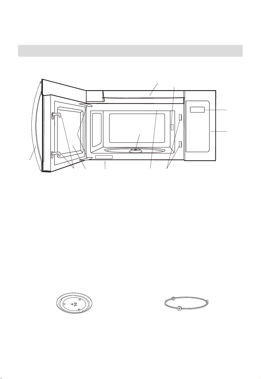
FR-13
APERÇU DU PRODUIT
Installation de votre four
NOMS DES PIÈCES
9
8
10
3
6 5
4
11
1
2
7
6
1. Porte du four à micro-ondes avec fenêtre transparente
2. Charnières de porte
3. Couvercle du guide d’ondes : NE PAS ENLEVER.
4. Arbre moteur du plateau tournant
5. Lumière du four à micro-ondes
Il s’allume lorsque le four à micro-ondes fonctionne ou que la porte est ouverte.
6. Verrous de sécurité de porte
Le four à micro-ondes ne fonctionne que si la porte est bien fermée.
7. Poignée
8. Panneau de commande
9. Affichage
10. Ouvertures de ventilation
11. Étiquette de notation
Plateau tournant en verre
Assemblage de la bague du plateau
tournant
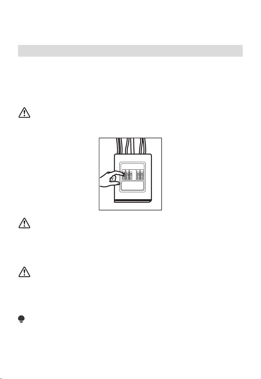
FR-14
INSTALLATION DU PRODUIT
Consignes de sécurité importantes
Ce produit nécessite une prise de courant à trois broches avec mise à la terre.
L'installateur doit vérifier la continuité de la mise à la terre du boîtier de prise de courant
avant de commencer l'installation afin de s'assurer que celui-ci est correctement mis
à la terre. Si la mise à la terre n'est pas correcte ou si la boîte de sortie ne répond pas
aux exigences électriques mentionnées (sous la rubrique EXIGENCES ÉLECTRIQUES), il
convient de faire appel à un électricien qualifié pour remédier à ces défauts.
MISE EN GARDE:
Pour votre sécurité personnelle, retirez le fusible de la maison ou désactivez le disjoncteur
avant de commencer l'installation pour éviter des blessures graves ou mortelles.
MISE EN GARDE:
Pour la sécurité personnelle, la surface de montage doit être capable de supporter la
charge de l'armoire, en plus du poids supplémentaire de ce produit de 63 à 85 livres (28,5
à 38,5 kg) , plus des charges de four supplémentaires allant jusqu'à 50 livres (22,7 kg) ou
un poids total de 113 à 135 livres (51,3 à 61,2 kg) .
MISE EN GARDE:
Pour des raisons de sécurité personnelle, ce produit ne peut pas être installé dans des
armoires telles qu'une île ou une péninsule. Il doit être monté à la FOIS sur une armoire
supérieure ET sur un mur.
REMARQUE :
Pour faciliter l'installation et procurer la sécurité personnelle, il est recommandé que
deux personnes installent ce produit.
IMPORTANT – VEUILLEZ LIRE ATTENTIVEMENT. POUR VOTRE SÉCURITÉ
PERSONNELLE, CET APPAREIL DOIT ÊTRE CORRECTEMENT MIS À LA TERRE POUR
ÉVITER UN CHOC GRAVE OU MORTEL.
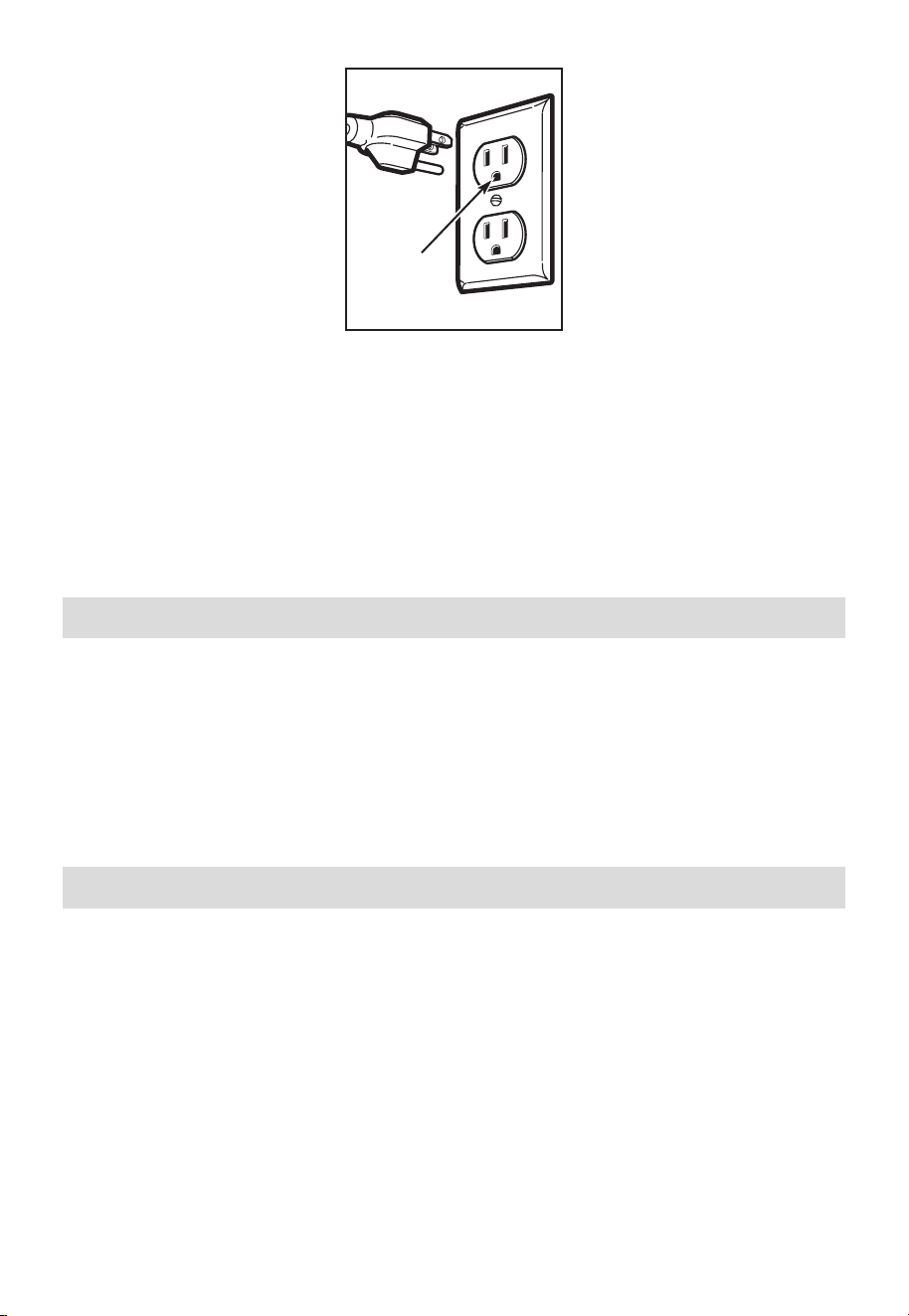
FR-15
Assurez-vous que
la mise à la terre
est correcte avant
l'utilisation
Le cordon d’alimentation de cet appareil est équipé d’une fiche à trois broches (mise à la
terre) qui s’adapte à une prise murale standard à trois broches également mise à la terre
afin de minimiser les risques de décharge électrique liés à cet appareil.
Vous devez faire vérifier la prise murale et le circuit par un électricien qualifié pour vous
assurer que la prise est correctement mise à la terre.
Lorsqu'une prise murale standard à deux fiches est présente, il est très important de la
faire remplacer par une prise murale à trois fiches correctement mise à la terre, installée
par un électricien qualifié.
NE JAMAIS, SOUS AUCUN PRÉTEXTE, COUPER, DÉFORMER OU RETIRER L'UNE DES
BROCHES DU CORDON D'ALIMENTATION. NE L’UTILISEZ PAS AVEC UNE RALLONGE.
Exigences électriques
La puissance nominale du produit est de 120 volts CA, 60 Hertz, 15 ampères et 1,55
kilowatts. Ce produit doit être connecté à un circuit d'alimentation séparé et dédié,
de tension et de fréquence appropriées. La taille des câbles doit être conforme aux
exigences du Code national de l'électricité ou du code local en vigueur pour cette
puissance en kilowatts. Le cordon d'alimentation et la fiche doivent être branchés sur
une prise de courant séparée et dédiée de 20 ampères avec mise à la terre. La boîte de
sortie doit être située dans l'armoire au-dessus du four à micro-ondes. La boîte sortie et
le circuit d’alimentation doivent être installés par un technicien qualifié et conformément
au Code national de l’électricité ou le code local en vigueur.
Dommages—Expédition/Installation
1. Si l'appareil est endommagé lors de l'expédition, renvoyez-le au magasin dans lequel
il a été acheté pour réparation ou remplacement.
2. Si l'appareil est endommagé par le client, la réparation ou le remplacement est à la
charge du client.
3. Si l'appareil est endommagé par l'installateur (s'il est autre que le client), la réparation
ou le remplacement doit être effectué par arrangement entre le client et l'installateur.
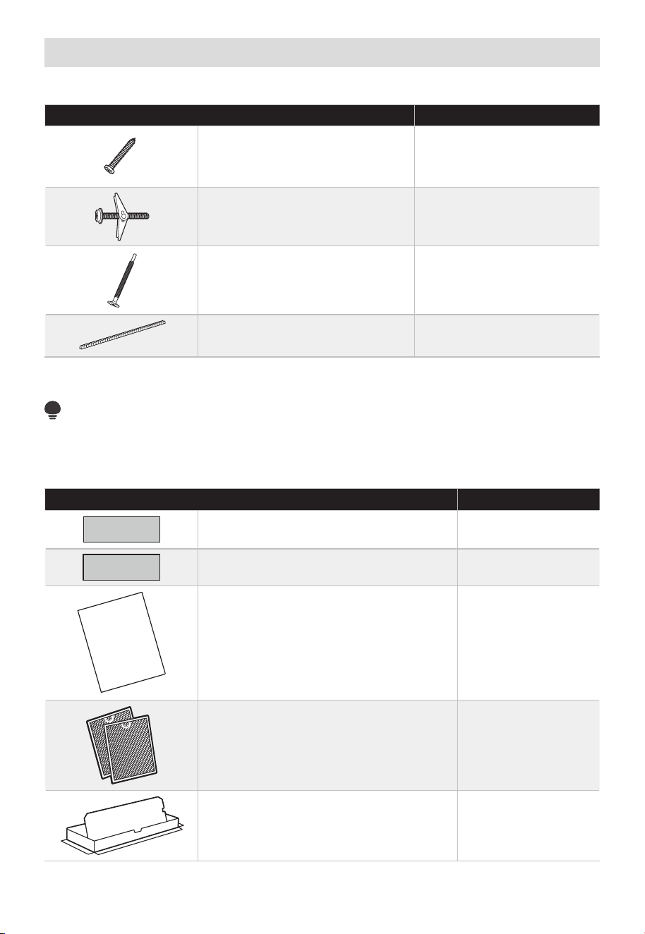
FR-16
Pièces incluses
PAQUET DE MATÉRIEL
PIÈCE QUANTITÉ
Vis à bois (
1
/
4
po x 2po) 2
Boulons à genouillère
(et écrous à oreilles)
(
3
/
16
po x 3po)
2
Vis de machine à
auto-alignement
(
1
/
4
po-28 x 3
1
/
4
po)
3
Oeillet en nylon (pour armoires
métalliques)
1
Vous trouverez le matériel d'installation contenu dans un paquet avec l'appareil. Vérifiez
que vous avez toutes ces pièces.
REMARQUE :
Certaines pièces supplémentaires sont incluses.
PIÈCES SUPPLÉMENTAIRES
PIÈCE QUANTITÉ
Modèle d'armoire supérieure 1
Modèle de mur arrière 1
USER
MANUAL
Manuel d'utilisation 1
Filtres à graisse emballés séparément 2
Adaptateur d'échappement 1
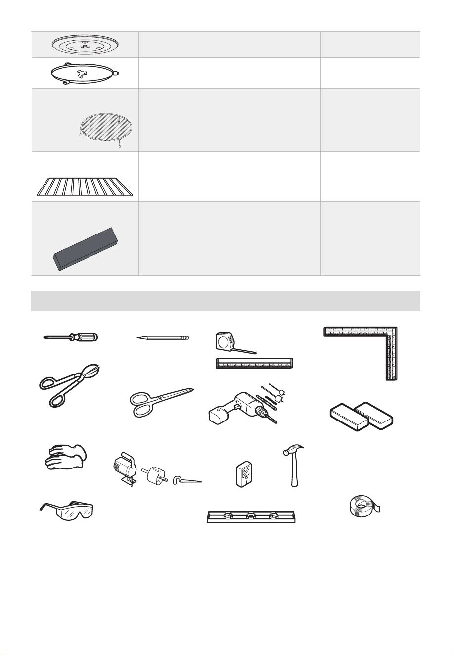
FR-17
Plateau en verre 1
Écrou de plaque tournante 1
(pour certains
modèles)
Grille métallique à convection 1
(pour certains
modèles)
Étagère 1
(pour certains
modèles)
Filtre à micro-ondes PureAir
®
1
Outils dont vous aurez besoin
# 1 Tournevis Phillips
Cisailles à toile (pour
amortisseur de coupe, si
nécessaire)
Ciseaux (pour couper
l'échantillon, si
nécessaire)
Perceuse électrique avec
forets
3
⁄
16
po,
1
⁄
2
po et
5
⁄
8
po
Blocs de remplissage ou
morceaux de bois de rebut, si
nécessaire pour l'espacement
de l'armoire supérieure
(utilisés uniquement sur
les installations d'armoires
inférieures encastrées)
Conduit et ruban de
masquage
Crayon
Gants
Lunettes de sécurité
Scie (sabre, trou ou trou
de serrure)
Localisateur de goujons ou
marteau (en option)
Niveau
Règle ou ruban à
mesurer et bord droit
Équerre de
menuisier (en
option)
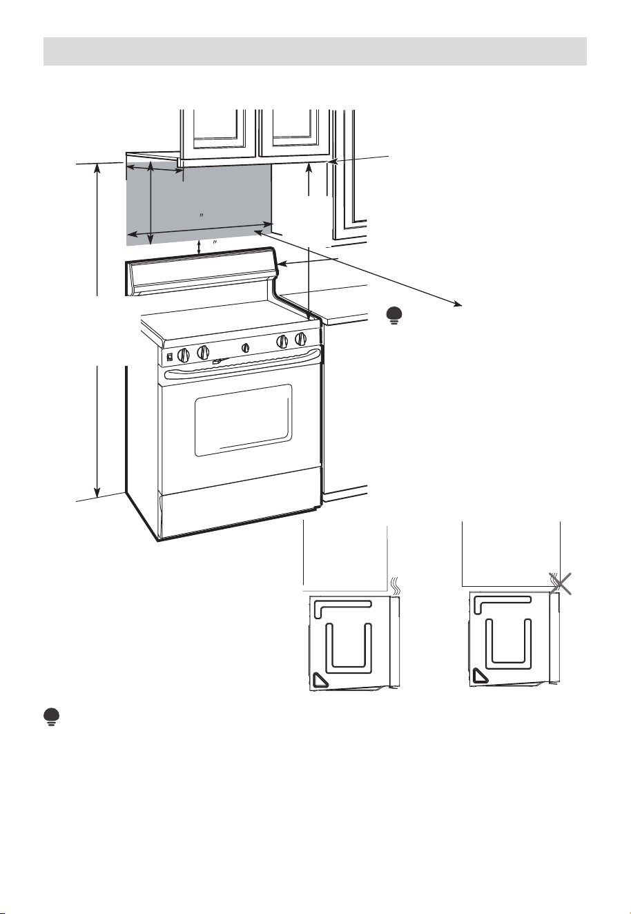
FR-18
Espace de montage
ESPACE DE MONTAGE
30 (76.2 cm)
2
(5.1cm)
16
1
⁄
2
(41.9 cm)
”
13po maximum (33 cm)
30po
(76,2 cm)
min.
Le bord inférieur de
l'armoire doit être à
30po (76,2 cm) ou
plus de la surface de
cuisson
Dosseret
66po (167,6
cm) ou plus du
sol au sommet
du micro-ondes
REMARQUE :
• Si la profondeur de l'armoire, y
compris les portes de l'armoire,
est supérieure à 13po, l'unité
doit être espacée du mur
en utilisant des matériaux
adéquats prenant en charge
150 lb pour permettre un
échappement/admission
appropriée de l'air par le haut.
REMARQUE :
• L'espace entre les armoires doit être de 30po (76,2 cm) de large et exempt d'obstructions.
• Si le four à micro-ondes doit être ventilé à l'extérieur, voir la section relative à
l'échappement de la hotte pour la préparation du conduit d'échappement.
• Lors de l'installation du four à micro-ondes sous des armoires lisses et plates, veillez à
suivre les consignes sur le modèle d'armoire supérieur pour le dégagement du cordon
d'alimentation.
• Pour diriger l'installation, consultez la page 25 pour obtenir des informations sur le
modèle de montage.
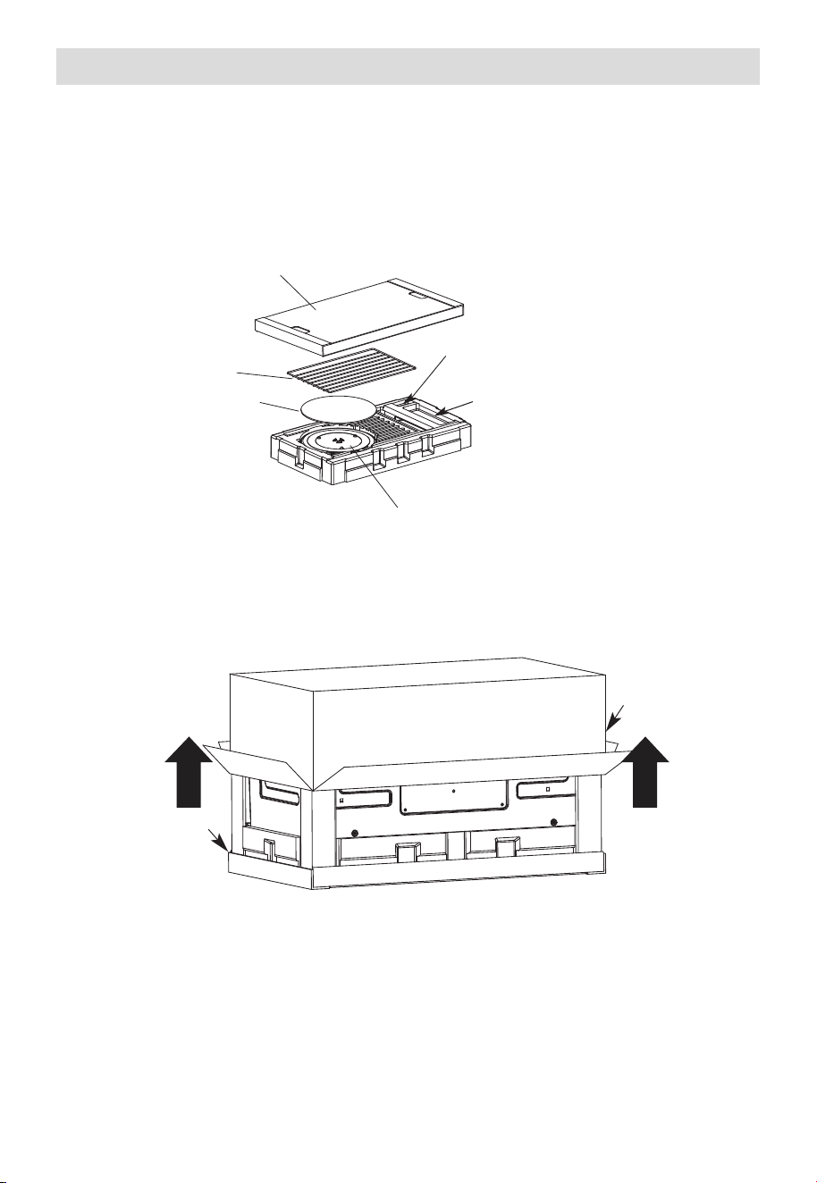
FR-19
1. Installation de la plaque de montage
A. RETRAIT DU FOUR À MICRO-ONDES DU CARTON/RETRAIT DE LA
PLAQUE DE MONTAGE
1. Retirez le panneau de couverture supérieur, les consignes d'installation, l'utilisation
et l'entretien, l'adaptateur d'échappement, l'écrou du plateau tournant, l'étagère, les
filtres, le plateau en verre et le petit sac de matériel. Ne retirez pas le polystyrène qui
protège l'avant du four.
Panneau de couverture supérieur
Petit sac de matériel
Adaptateur d'échappement
Étagère
(pour certains
modèles)
Tampon EPE
Filtres et anneau de plaque tournante sous le plateau en verre
2. Repliez complètement les 4 rabats du carton contre les côtés du carton. Ensuite,
roulez soigneusement le four et le carton sur la face supérieure. Le four doit reposer
dans le polystyrène.
Polystyrène
Carton
3. Tirez le carton vers le haut et éteignez le four.
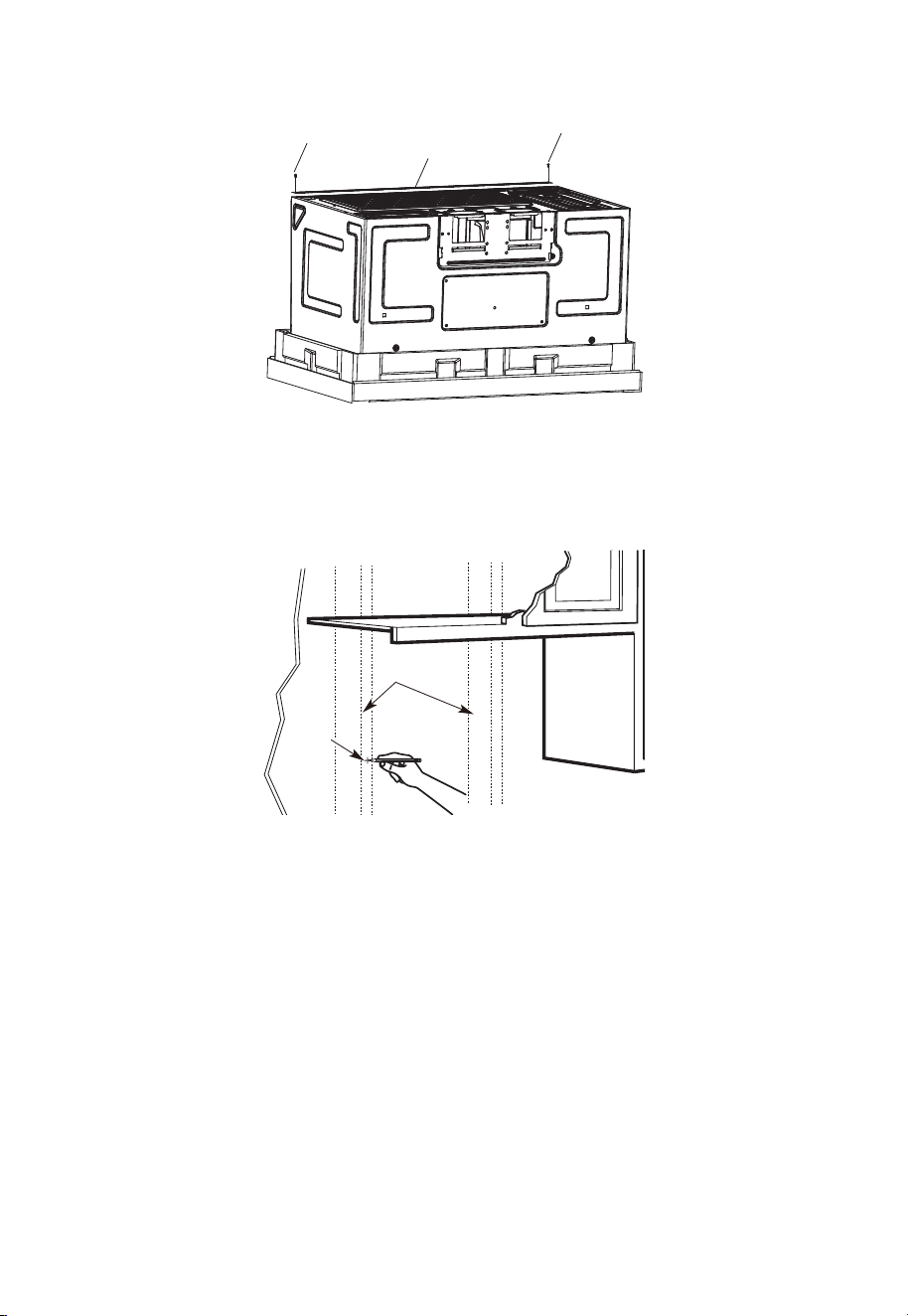
FR-20
4. Coupez le milieu du sac en plastique de protection externe pour retirer la plaque de
montage
Vis
Plaque de montage
Vis
5. Retirez les vis de chaque extrémité de la plaque de montage. Cette plaque sera
utilisée comme modèle de paroi arrière et pour le montage. Réinstallez les vis dans les
trous où elles ont été retirées.
B. REPÉRAGE LES POTEAUX MURAUX
Centre
Poteaux
muraux
1. Répérez les poteaux muraux en utilisant l’une des méthodes suivantes :
-
Répéreur de poteaux muraux – un matériel magnétique qui localise les clous.
-
Utilisez un marteau pour taper légèrement sur la surface de montage pour trouver
un son solide. Cela indiquera un emplacement de poteau.
2. Après avoir localisé le (s) poteau(s), trouvez le centre en sondant le mur avec un petit
clou pour trouver les bords du poteau. Placez ensuite une marque à mi-chemin entre
les bords. Le centre de tous les poteaux adjacents doit être à 16po (40,6 cm) ou 24po
(61 cm) de cette marque.
3. Tracez une ligne au centre des poteau.
LE MICRO-ONDES DOIT ÊTRE CONNECTÉ À AU MOINS UN POTEAU MURAL.
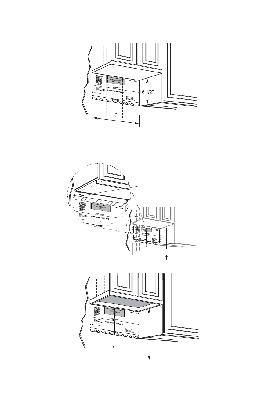
FR-21
C. DÉTERMINATION DE L'EMPLACEMENT DE LA PLAQUE MURALE SOUS
VOTRE ARMOIRE
Position de la plaque - sous l'armoire à fond plat
Au moins 30po
Tracez une ligne verticale sur le mur au centre de l'espace de 30po de large.
Collez le modèle de mur arrière sur le mur correspondant à la ligne centrale et en
touchant le bas de l'armoire.
Position de la plaque - sous l'armoire inférieure encastrée avec un débordement à l'avant
Tracez une ligne sur
le mur arrière égale
à la profondeur du
débordement avant.
30po vers la plaque de cuisson
Position de la plaque - sous le fond de l'armoire encastrée et encadrée
30po vers la plaque de cuisson
Tracez une ligne verticale sur le mur au centre de l'espace de 30po.
Collez le modèle de mur arrière sur le mur correspondant à la ligne centrale et en
touchant le cadre inférieur de l'armoire.
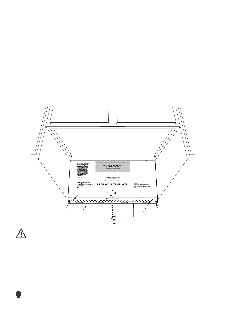
FR-22
Vos armoires peuvent avoir des garnitures décoratives qui interfèrent avec l'installation
du micro-ondes. Retirez la garniture décorative pour installer correctement le micro-
ondes et le mettre à niveau.
LE MICRO-ONDES DOIT ÊTRE DE NIVEAU.
Utilisez un niveau d'eau pour vous assurer que le fond de l'armoire est de niveau.
Si les armoires ont un débordement avant uniquement, sans cadre arrière ou latéral,
installez la plaque de montage à la même distance que la profondeur du débordement
avant. Cela maintiendra le niveau du micro-ondes.
1. Mesurez la profondeur intérieure du débordement avant.
2. Tracez une ligne horizontale sur le mur arrière à une distance égale sous le fond de
l'armoire que la profondeur intérieure du débordement avant.
3. Pour ce type d'installation avec débordement avant uniquement, alignez les pattes de
montage sur cette ligne horizontale, sans toucher le fond de l'armoire comme décrit à
l'étape D.
D. ALIGNEMENT DE LA PLAQUE MURALE
3/8" TO EDGE
Ligne
horizontale
Zone E
Tracez une ligne horizontale sur le mur
au bas du « modèle de mur arrière ».
Trou A
Ligne horizontale
Trou B
Encoches de
l'axe central
Dessinez une ligne verticale
sur le mur à partir du centre
de l'armoire supérieure
MISE EN GARDE:
Portez des gants pour éviter de couper les doigts sur les bords tranchants.
1. Tracez une ligne verticale sur le mur au centre de l'espace de 30po de large.
2. Tracez une ligne horizontale sur le mur au bas du «modèle de mur arrière ».
3. Trouvez un goujon mural dans la zone « E » de la plaque de montage. Reportez-vous
à la section 1B. Repérage des poteaux muraux.
4. Pour fixer la plaque de montage dans le poteau, percez un trou de 3/16po dans le
poteau en bois. Percez un trou de 5/8po pour le boulon à genouillère à un autre
endroit (trou A ou trou B)
REMARQUE :
NE MONTEZ PAS LA PLAQUE POUR LE MOMENT.
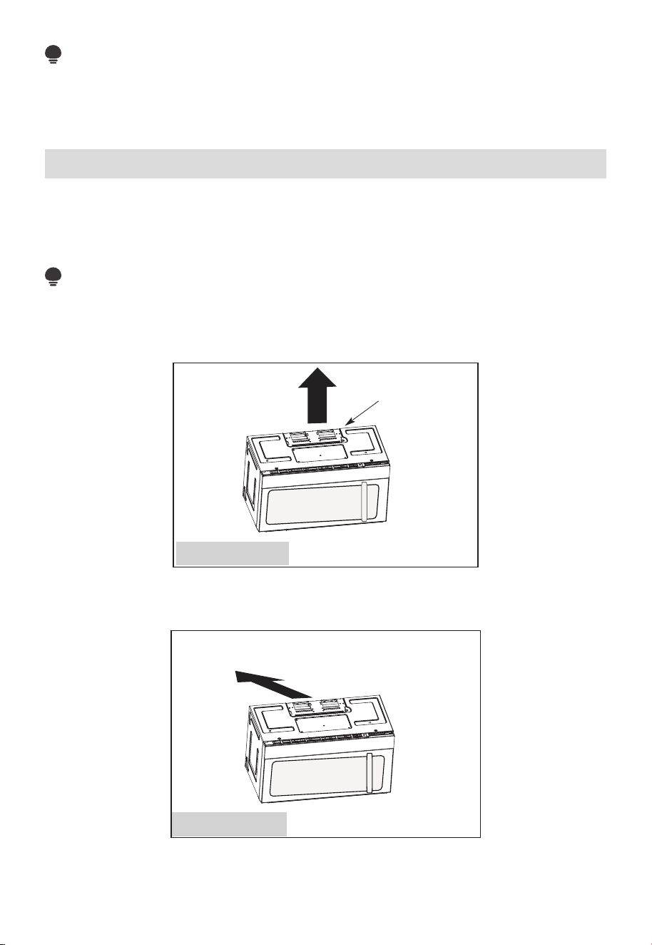
FR-23
REMARQUE :
Les trous A et B sont à l'intérieur de la zone E. Si aucun des trous A et B n'est dans un
poteau, trouvez un autre quelque part dans la zone E et tracez un cercle pour l'aligner avec
le poteau. Il est important d'avoir au moins une vis à bois montée fermement dans un poteau
pour supporter le poids du micro-ondes. Mettez la plaque de montage de côté.
2. Types d'installation (choisissez A, B ou C)
Ce four à micro-ondes est conçu pour s'adapter aux trois types de ventilation suivants :
A. Échappement supérieur extérieur (conduit vertical)
B. Échappement arrière extérieur (conduit horizontal)
C. Recirculation (sans conduit de ventilation)
REMARQUE :
Ce micro-ondes est expédié assemblé pour la recirculation. Sélectionnez le type de
ventilation requis pour votre installation et passez à cette section.
A. ÉCHAPPEMENT SUPÉRIEUR EXTÉRIEUR (CONDUIT VERTICAL)
Adaptateur en place
pour l'échappement
supérieur extérieur
Voir page 26
B. ÉCHAPPEMENT ARRIÈRE EXTÉRIEUR (CONDUIT HORIZONTAL)
L'adaptateur doit être
déplacé vers l'arrière
pour l'échappement
arrière extérieur
Voir page 33
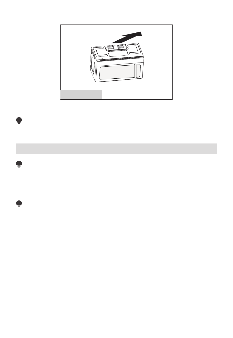
FR-24
C. RECIRCULATION (SANS CONDUIT DE VENTILATION)
Voir page 41
Les modèles sont expédiés avec un système de ventilation à recirculation. Certains modèles
disposent d'un filtre à charbon jetable installé pour aider à éliminer la fumée et les odeurs.
REMARQUE :
Lisez les deux pages suivantes uniquement si vous prévoyez d'évacuer vos gaz d'échappement
vers l'extérieur. Si vous prévoyez de faire recirculer l'air dans la pièce, allez à la page 23-26.
Consignes d'installation pour les conduits d'échappement externes
REMARQUE :
Si vous devez installer des conduits, notez que la longueur totale du conduit de 3
1
/
4
po
x 10po (8,2 x 25,4 cm) rectangulaire ou 5po (12,7 cm) de diamètre/ 6po (15,2 cm) de
diamètre de conduit rond ne doit pas dépasser 120 pieds équivalents (36,5 m).
La ventilation extérieure nécessite un CONDUIT D'ÉCHAPPEMENT EXTERNE .Lisez
attentivement ce qui suit.
REMARQUE :
Il est important que la ventilation soit installée en utilisant la voie la plus directe et avec
le moins de coudes possible. Cela garantit une ventilation claire des gaz d'échappement
et aide à prévenir les blocages. Assurez-vous également que les amortisseurs oscillent
librement et que rien ne bloque les conduits.
Raccord d'échappement:
L'adaptateur d'échappement a été conçu pour s'accoupler avec un conduit rectangulaire
standard de 3
1
/
4
po x 10po (8,2 x 25,4 cm).
Si un conduit rond est nécessaire, un adaptateur de transition rectangulaire à rond doit être
utilisé. Un conduit de diamètre A5 po (12,7 cm)/ 6po (15,2 cm) est acceptable à utiliser.
Longueur maximale du conduit:
Pour un mouvement d'air satisfaisant, la longueur totale du conduit de 3
1
/
4
po x 10po
(8,2 x 25,4 cm) rectangulaire ou 5po (12,7 cm) de diamètre/ 6 po(15,2 cm) de diamètre
de conduit rond ne doit pas dépasser 120 pieds équivalents (36,5 m).
Les coudes, les transitions, les capuchons de mur et de toit, etc., présentent une
résistance supplémentaire au flux d'air et sont équivalents à une section de conduit droit
qui est plus longue que leur taille physique réelle. Lors du calcul de la longueur totale du
conduit, ajoutez les longueurs équivalentes de toutes les transitions et adaptateurs plus
la longueur de toutes les sections droites du conduit. Le tableau ci-dessous vous montre
comment calculer la longueur équivalente totale des conduits en utilisant les pieds
approximatifs de longueur équivalente de certains conduits typiques.
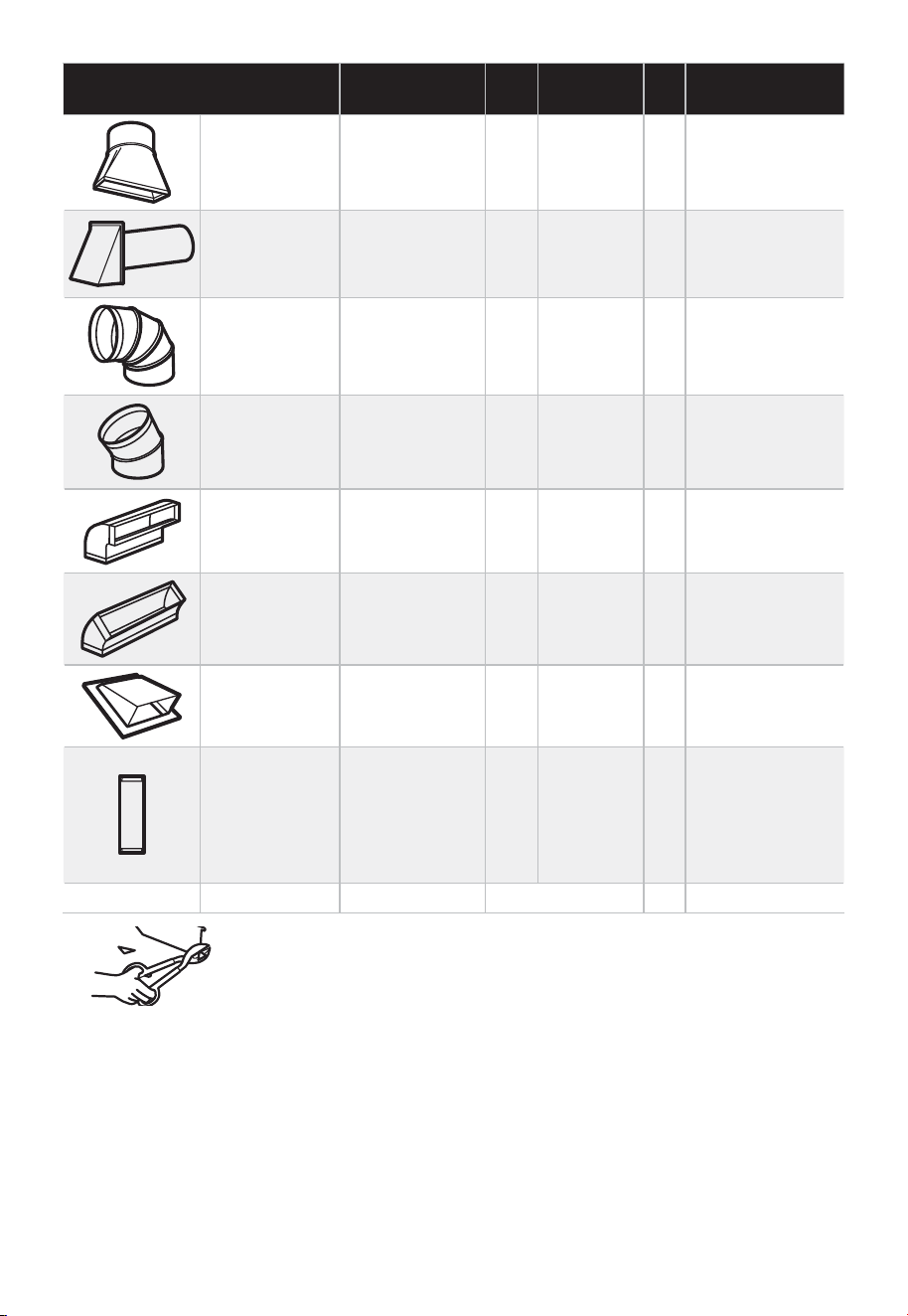
FR-25
PIÈCES DE CONDUIT
LONGUEUR
ÉQUIVALENTE
x
NOMBRE
UTILISÉ
=
LONGUEUR
ÉQUIVALENTE
Adaptateur
de transition
rectangulaire
à rond*
5 pi. (1,5 m) x ( ) = Pieds. ou m
Capuchon
mural
40 pi. (12,2 m) x ( ) = Pieds. ou m
Coude à 90° 10 pi. (3 m) x ( ) = Pieds. ou m
Coude à 45° 5 pi. (1,5 m) x ( ) = Pieds. ou m
Coude à 90° 25 pi. (7,6 m) x ( ) = Pieds. ou m
Coude à 45° 5 pi. (1,5 m) x ( ) = Pieds. ou m
Capuchon de
toit
24 pi. (7,3 m) x ( ) = Pieds. ou m
Conduit droit
6po (15,2
cm) rond ou
3
1
/
4
po x 10po
(8,2 x 25,4 cm
rectangulaire)
1 pi. (0,3 m) x ( ) = Pieds. ou m
Total des gaines = Pieds. ou m
* IMPORTANT : Si un adaptateur de transition rectangulaire
à rond est utilisé, les coins inférieurs de l'amortisseur devront
être coupés pour s'adapter, à l'aide des cisailles à toile, afin de
permettre le libre mouvement de l'amortisseur.
Les longueurs équivalentes des pièces de conduit sont basées sur des tests réels et
reflètent les exigences de bonnes performances de ventilation avec n'importe quelle
hotte de ventilation.
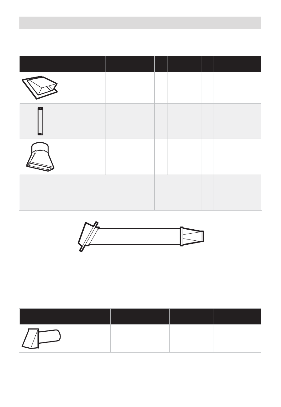
FR-26
Conduites d'échappement externes
ÉCHAPPEMENT SUPÉRIEUR EXTÉRIEUR (EXEMPLE UNIQUEMENT)
Le tableau suivant décrit un exemple d'installation de gaines possible.
PIÈCES DE CONDUIT
LONGUEUR
ÉQUIVALENTE
x
NOMBRE
UTILISÉ
=
LONGUEUR
ÉQUIVALENTE
Capuchon de
toit
24 pi. (7,3 m) x (1) = 24 pi. (7,3 m)
12 pi.
(3,6 m)
Conduit
droit (rond
6po/15,2 cm)
12 pi. (3,6 m) x (1) = 12 pi. (3,6 m)
Adaptateur
de transition
rectangulaire
à rond *
5 pi. (1,5 m) x (1) = 5 pi. (1,5 m)
Les longueurs équivalentes des pièces de
conduit sont basées sur des tests réels et
reflètent les exigences de bonnes performances
de ventilation avec n'importe quelle hotte de
ventilation.
Longueur
totale
= 41 pi. (12,5 m)
* IMPORTANT : Si un adaptateur de transition rectangulaire à rond est utilisé, les coins
inférieurs de l'amortisseur devront être coupés pour s'adapter, à l'aide des cisailles à
toile, afin de permettre le libre mouvement de l'amortisseur.
ÉCHAPPEMENT ARRIÈRE EXTÉRIEUR (EXEMPLE UNIQUEMENT)
Le tableau suivant décrit un exemple d'installation de gaines possible.
PIÈCES DE CONDUIT
LONGUEUR
ÉQUIVALENTE
x
NOMBRE
UTILISÉ
=
LONGUEUR
ÉQUIVALENTE
Capuchon
mural
40 pi. (12,2 m) x (1) = 40 pi. (12,2 m)
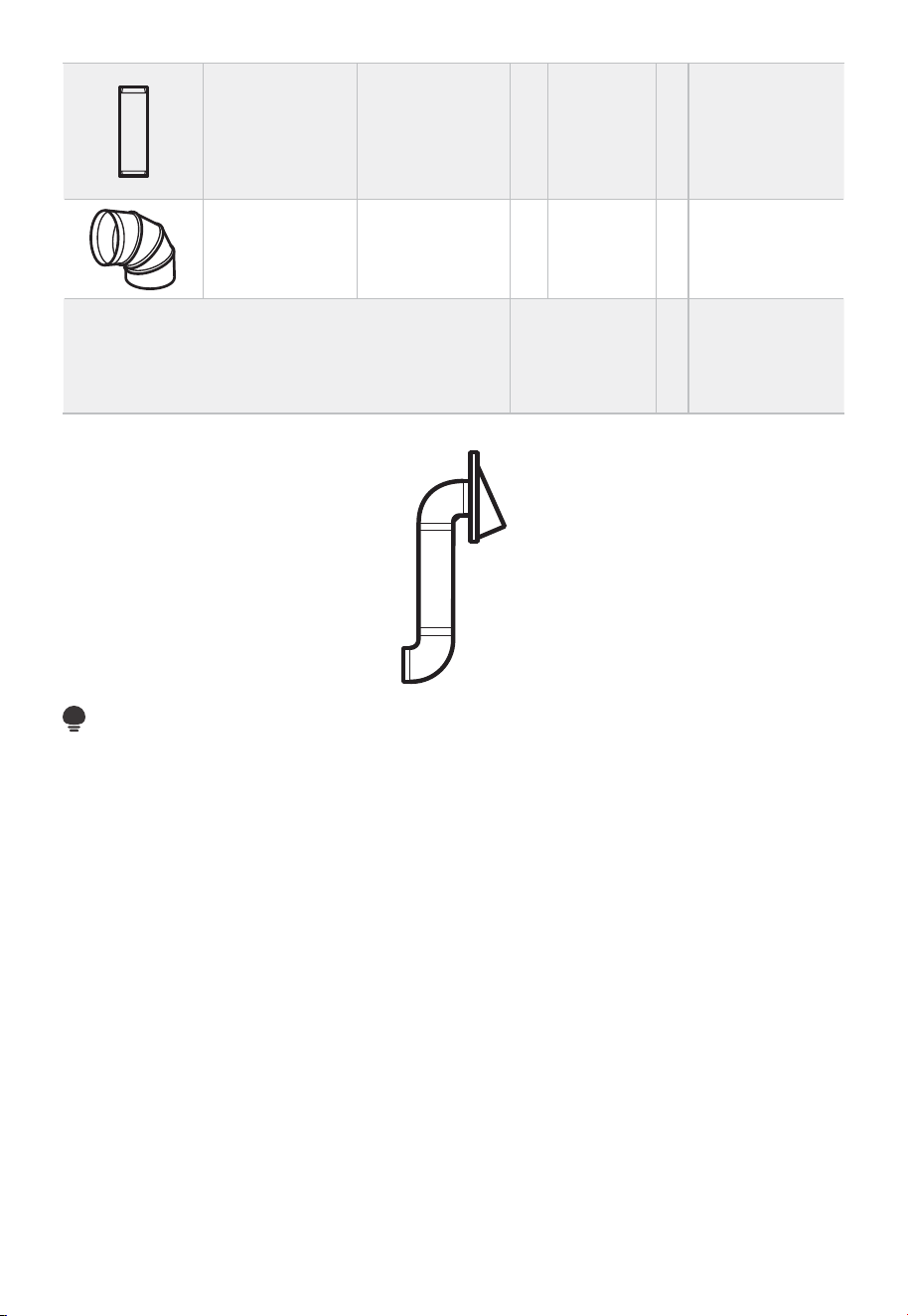
FR-27
3 pi. Conduit
droit
(rectangulaire
de 3
1
/
4
po x
10po/8,2 x
25,4 cm)
3 pi. (0,9 m) x (1) = 3 pi. (0,9 m)
Coude à 90° 10 pi. (3 m) x (2) = 20 pi. (3 m)
Les longueurs équivalentes des pièces de
conduit sont basées sur des tests réels et
reflètent les exigences de bonnes performances
de ventilation avec n'importe quelle hotte de
ventilation.
Longueur
totale
= 63 pi. (19,2 m)
REMARQUE :
Pour l'échappement arrière, il faut prendre soin d'aligner l'échappement avec l'espace
entre les poteaux, ou le mur doit être préparé au moment de sa construction en laissant
suffisamment d'espace entre ceux-ci pour accueillir l'échappement.
A. ÉCHAPPEMENT SUPÉRIEUR EXTÉRIEUR (conduit vertical)
APERÇU DE L'INSTALLATION
A1. Fixez la plaque de montage au mur
A2. Préparez l'armoire supérieure
A3. Configurez le souffleur à micro-ondes pour l'échappement extérieur / supérieur
A4. Vérifiez le fonctionnement de l'amortisseur
A5. Montez le four à micro-ondes
A6. Régler l'adaptateur d'échappement
A7. Connectez les gaines
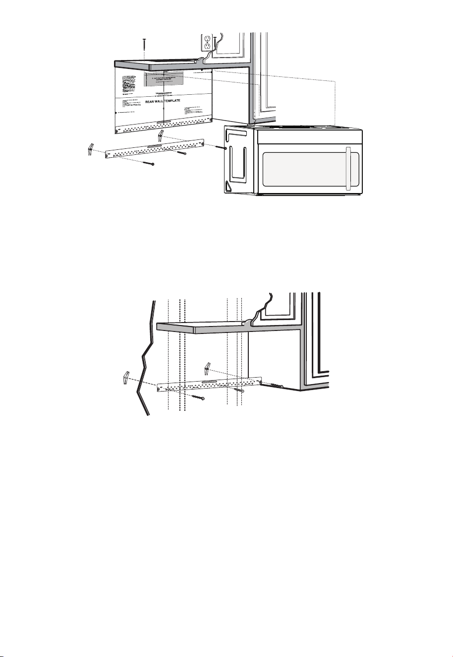
FR-28
REMARQUES IMPORTANTES :
1. Assurez-vous que les vis du moteur du souffleur et de la plaque du souffleur sont bien
serrées lors de leur installation. Cela aidera à éviter les vibrations excessives.
2. Assurez-vous que le câblage du moteur a été correctement acheminé et sécurisé, et
que les câbles ne sont pas pincés.
A1. FIXEZ LA PLAQUE DE MONTAGE AU MUR
• Fixez la plaque au mur à l'aide de boulons à genouillère.
• Au moins une vis à bois doit être utilisée pour fixer la plaque à un poteau mural.
1. Retirez les ailettes à genouillère des boulons
2. Insérez les boulons dans la plaque de montage à travers les trous destinés à entrer
dans la cloison sèche et fixez à nouveau les ailettes à genouillère à 3/4po (19 mm) sur
chaque boulon.
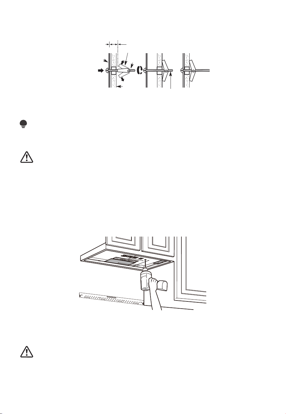
FR-29
Pour utiliser les boulons à genouillère:
Plaque de
montage
Espacement pour les
bascules de plus de
l'épaisseur du mur
Ailettes à genouillère
Boulon à
genouillère
Extrémité du boulon
Mur
3. Placez la plaque de montage contre le mur et insérez les ailettes à genouillère dans
les trous du mur pour monter la plaque.
REMARQUE :
Avant de serrer les boulons à genouillère et la vis à bois, assurez-vous que le bas de la
plaque de montage touche le bas de l'armoire lorsqu'il est poussé contre le mur et que la
plaque est correctement centrée sous l'armoire.
MISE EN GARDE:
Soyez prudent et évitez de pincer les doigts entre l'arrière de la plaque de montage et le
mur.
4. Serrez tous les boulons. Retirez la plaque du mur pour aider à serrer les boulons.
A2. UTILISER LE MODÈLE D'ARMOIRE SUPÉRIEURE POUR LA PRÉPARATION
DE L'ARMOIRE SUPÉRIEURE
Vous devez percer des trous pour les vis de support supérieures, un trou suffisamment
grand pour le cordon d'alimentation et une découpe suffisamment grande pour
l'adaptateur d'échappement.
1. Lisez les consignes relatives au MODÈLE D'ARMOIRE SUPÉRIEUR.
2. Collez-le sous l'armoire supérieure.
3. Percez les trous en suivant les consignes relatives au MODÈLE D'ARMOIRE
SUPÉRIEUR.
MISE EN GARDE:
Portez des lunettes de sécurité lorsque vous percez des trous dans le fond de l'armoire.
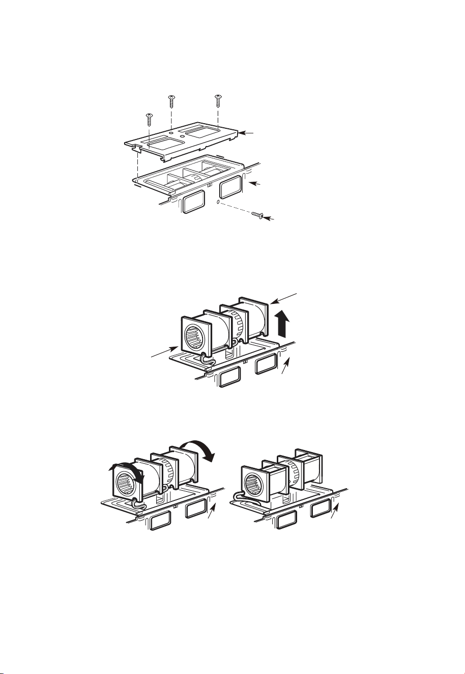
FR-30
A3. ADAPTATION DU SOUFFLEUR DU MICRO-ONDES POUR L'ÉCHAPPEMENT
SUPÉRIEUR EXTÉRIEUR
1. Placez le micro-ondes en position verticale, avec la partie supérieure de l'appareil
orientée vers le haut.
Plaque de
soufflage
Arrière du
micro-ondes
Vis du moteur
du souffleur
Retirez la vis qui maintient la plaque du souffleur au micro-ondes. Retirez et conservez la
vis, en maintenant le moteur du souffleur au micro-ondes.
2. Retirez délicatement l'unité de soufflage. Les câbles s'étendront suffisamment loin
pour vous permettre de régler l'unité de soufflage.
Extrémité B
Extrémité A
Arrière du
micro-ondes
3. Faites rouler l'unité de soufflage à 90° de sorte que les ouvertures des pales du
ventilateur soient tournées vers le haut du micro-ondes.
Avant la rotation
Après la rotation
Arrière du
micro-ondes
Arrière du
micro-ondes
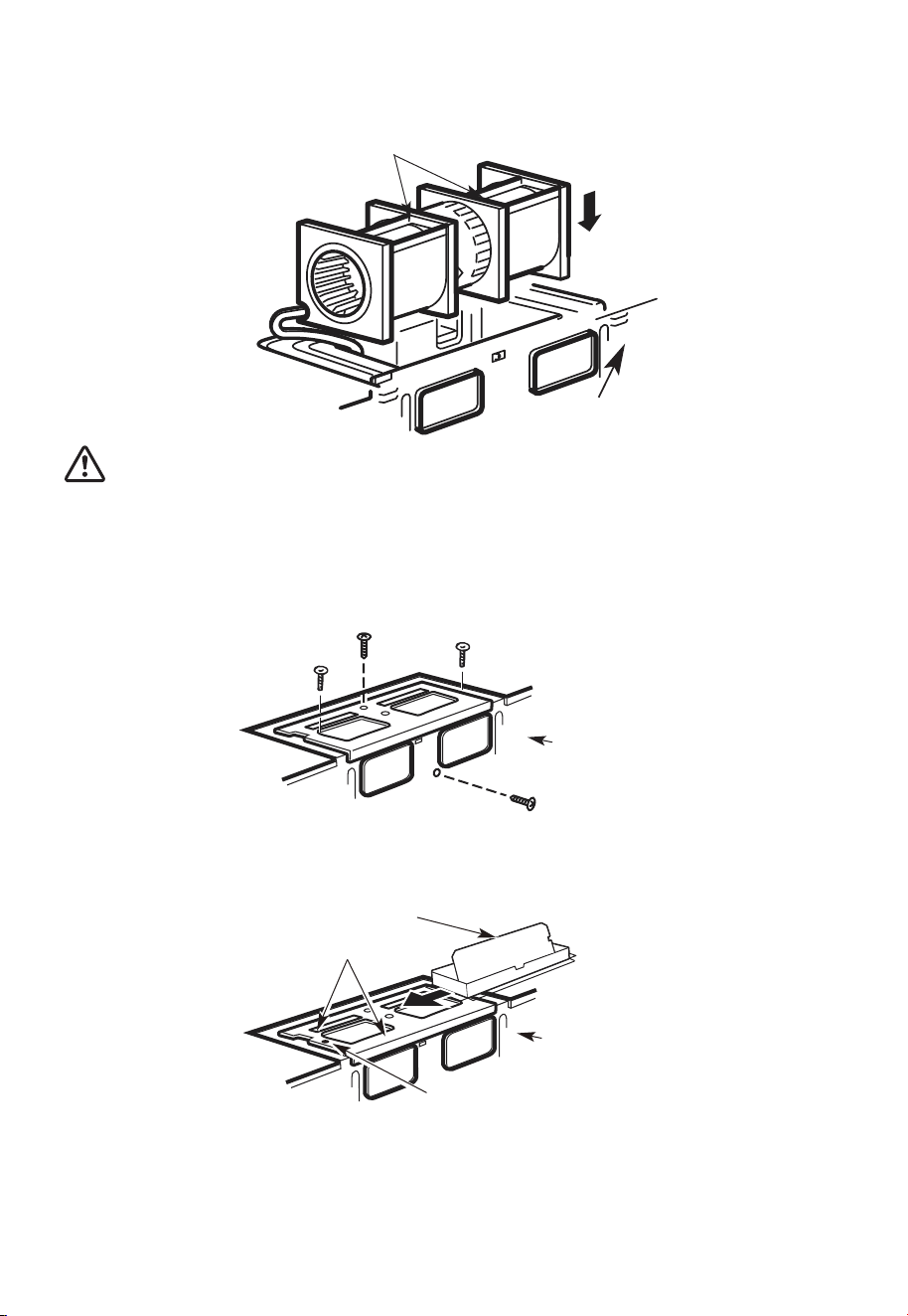
FR-31
4. Replacez l'unité de soufflage dans l'ouverture.
APRÈS : Ouvertures des pales de
ventilateur orientées vers le haut
Arrière du
micro-ondes
MISE EN GARDE:
Ne tirez ni n'étirez le câblage de l'unité de soufflage. Assurez-vous que les câbles ne sont
pas pincés et qu'ils sont correctement fixés.
5. Fixez l'unité de soufflage au micro-ondes avec la vis retirée à l'étape 1. Assurez-vous
que la vis est bien serrée.
6. Remplacez la plaque du souffleur avec la vis retirée à l'étape 1. Assurez-vous que la vis
est bien serrée.
Arrière du
micro-ondes
7. Fixez l'adaptateur d'échappement au sommet de la plaque du souffleur en le faisant
glisser dans les guides de la plaque du souffleur.
Adaptateur
Guide
Onglet de verrouillage
Arrière du
micro-ondes
Poussez fermement jusqu'à ce qu'il soit dans les languettes de verrouillage. Veillez à ce
que la charnière de l'amortisseur soit installée de manière à ce que l'amortisseur oscille
librement.
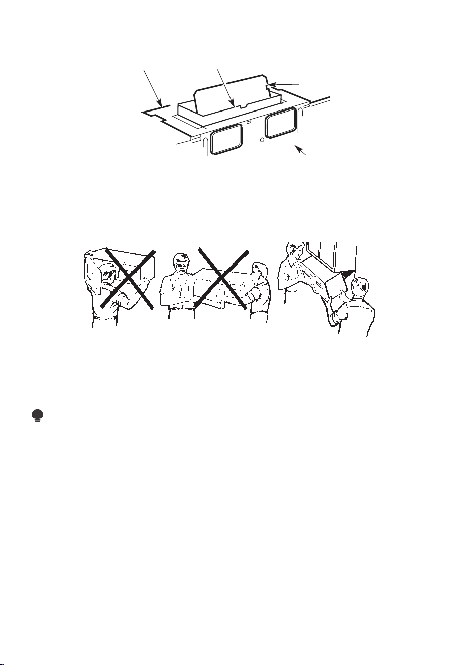
FR-32
A4. VÉRIFIEZ LE BON FONCTIONNEMENT DE L'AMORTISSEUR
Arrière du
micro-ondes
Amortisseur
Adaptateur d'échappementPlaque de soufflage
• Assurez-vous que le ruban adhésif fixant l'amortisseur est retiré et que le celui-ci
pivote facilement avant de monter le micro-ondes.
• Vous devrez effectuer des ajustements pour vous assurer d'un alignement correct
avec le conduit d'échappement de votre maison après l'installation du micro-ondes.
A5. MONTER LE FOUR À MICRO-ONDES
POUR FACILITER L'INSTALLATION ET PROCURER LA SÉCURITÉ PERSONNELLE,
NOUS VOUS RECOMMANDONS QUE DEUX PERSONNES INSTALLENT CE FOUR À
MICRO-ONDES.
IMPORTANT : Ne saisissez pas et n'utilisez pas la poignée ou le bouclier thermique
pendant l'installation. Ne retirez pas les entretoises en carton entre le bouclier thermique
et la porte.
REMARQUE :
Si votre armoire est en métal, utilisez l'œillet en nylon autour du trou du cordon
d'alimentation pour éviter de couper celui-ci.
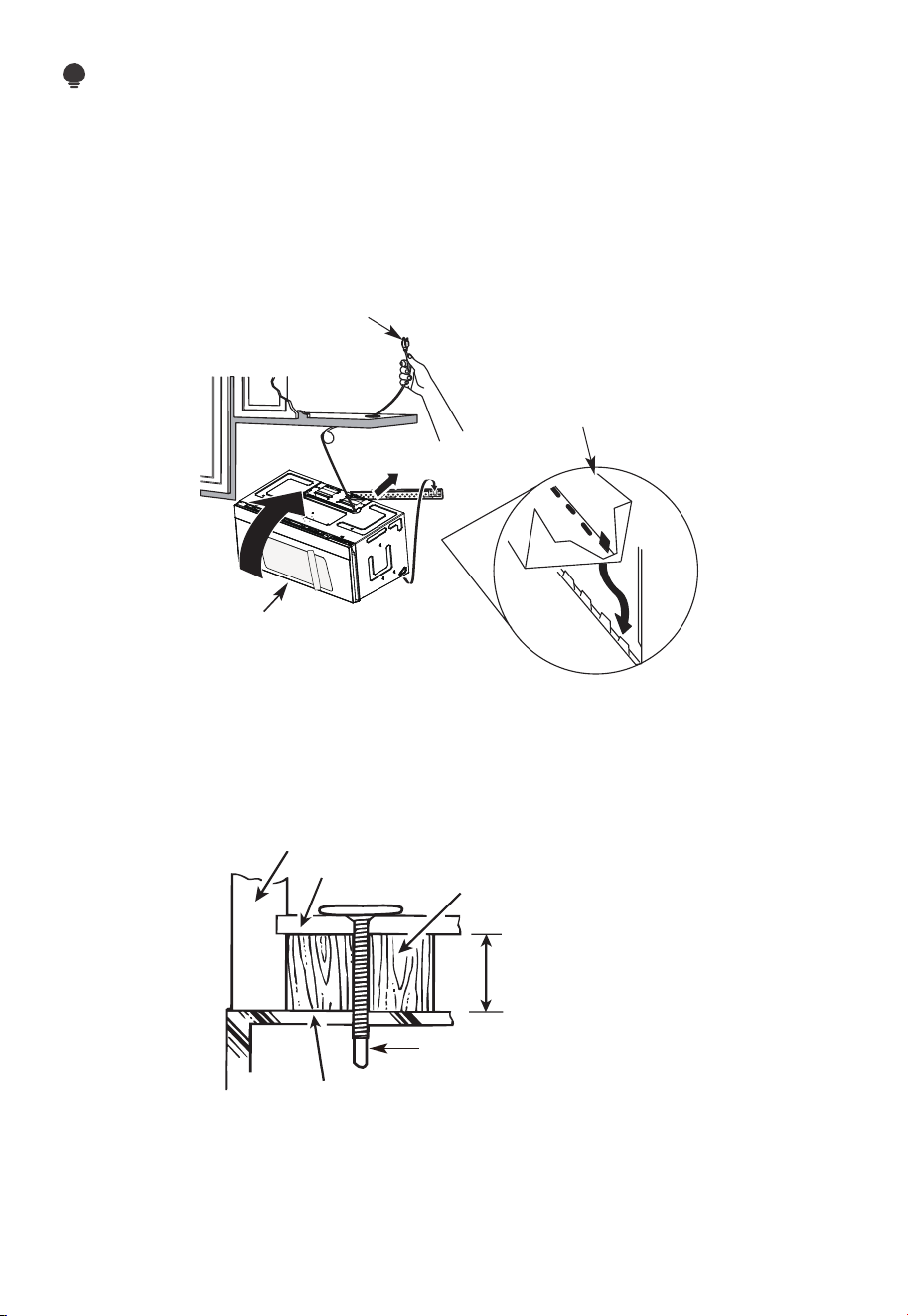
FR-33
REMARQUE :
Nous vous recommandons d'utiliser des blocs de remplissage si l'avant de l'armoire est
suspendu sous de l'étagère inférieure de celle-ci.
IMPORTANT : Si les blocs de remplissage ne sont pas utilisés, le serrage excessif des vis
peut endommager le boîtier.
REMARQUE : Lors du montage du four à
micro-ondes, enfilez le cordon d'alimentation
à travers le trou situé au bas de l'armoire
supérieure. Gardez-la bien serrée tout au long
des étapes 1 à 3. Ne pincez pas le cordon ou ne
soulevez pas le four en tirant sur le cordon.
1. Soulevez le micro-ondes,
inclinez-le vers l'avant et
accrochez les fentes du bord
inférieur arrière sur quatre
languettes inférieures de la
plaque de montage.
2. Tournez l'avant du
four contre le fond de
l'armoire.
3. Insérez une vis à alignement automatique dans le trou central supérieur de l'armoire.
Fixez temporairement le four en tournant la vis d'au moins deux tours complets après
l'engagement des fils. (Il sera complètement serré plus tard.) Assurez-vous de garder
le cordon d'alimentation serré. Veillez à ne pas pincer le cordon, en particulier lors du
montage affleurant au bas de l'armoire.
Façade de l'armoire
Étagère inférieure de l'armoire
Bloc de
remplissage
Équivalent à la profondeur
de l'encastrement de
l'armoire
Vis à alignement
automatique
Dessus du four à micro-ondes
4. Fixez le four à micro-ondes à l'armoire supérieure.
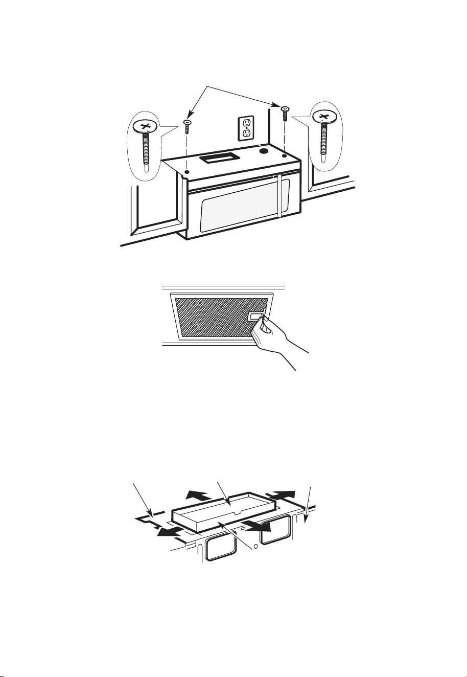
FR-34
5. Insérez 2 vis à alignement automatique
à travers les trous extérieurs de
l'armoire supérieure. Tournez deux
tours complets sur chaque vis.
6. Serrez les deux vis extérieures au sommet du four à micro-ondes. (Tout en serrant les
vis, maintenez le four à micro-ondes en place contre le mur et l'armoire supérieure.)
7. Installez des filtres à graisse. Voir le guide relatif à l'utilisation et à l'entretien emballé
avec le micro-ondes.
A6. RÉGLER L'ADAPTATEUR D'ÉCHAPPEMENT
Ouvrez l'armoire supérieure et réglez l'adaptateur d'échappement pour le connecter au
conduit de la maison.
Plaque de
soufflage
Amortisseur
Arrière du
micro-ondes
Pour le réglage d'avant en
arrière ou d'un côté à l'autre,
faites glisser l'adaptateur
d'échappement au besoin
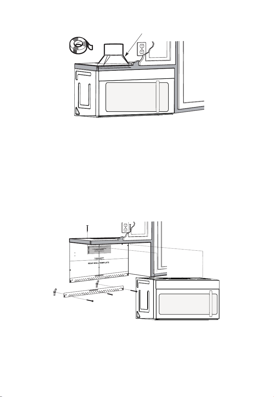
FR-35
A7. RACCORDEMENT DES GAINES
Conduit de la maison
1. Étendez le conduit de la maison vers le bas pour le connecter à l'adaptateur
d'échappement.
2. Scellez les joints du conduit d'échappement à l'aide de ruban adhésif de conduit de
four pour les applications à haute température
B. ÉCHAPPEMENT ARRIÈRE EXTÉRIEUR (conduit horizontal)
APERÇU DE L'INSTALLATION
B1. Préparez le mur arrière
B2. Retirer la plaque du souffleur
B3. Fixez la plaque de montage au mur
B4. Préparez l'armoire supérieure
B5. Réglez le souffleur
B6. Monter le four à micro-ondes
12"
4"
NO
TE
:
REA
D AND F
O
I
T
I
S
V
ER
Y
LLO
I
W
MPO
T
HE
R
D
TA
NT T
O
IRECTIO
IN THE INSTALLAT
I
O
N INSTRU
CTI
O
N
N
S
S
B
EF
O
RE PRO
H
T
H T I
W
G NI
D E
E
C IS
REAR WA
L
L TEM
PL
ATE.
ll Templ
a
te s
erv
es t
o p
1
ou
a
. Us
mo
u
tle
t.
ntin
e
a l
T
h
is
R
ea
g
p
r
W
l
a
a
t
e
a
nd
to
lo
ca
te
th
e h
or
iz
o
s
o
n
itio
t
a
n
l e
t
h
xh
e b
au
o
st
t
t
o
m
ioned
to
c
hec
k tha
t
th
e
t
e
m
pl
ate is
p
osit
pl
ark
holes
to ali
gn
wi
th holes
i
n theL
ocat
mounting
RTANT
e and m
:
ate.
IMP
O
E AT LEA
THE
CENT
HE LO
CATIO
L
O
C
AT
ERLINE
ST
.
O
NE STUD
ON EI
F
O
E
D I S R
E H
T
SP
AC
E
AREA.
MAR
KT
D TOGGLE BO
NF
LTS
O
I
N
R 2 ADDI
T
THE MO
IO
UN
NA
T
ING
L, EVENL
P
LATE
Y
Trim the
r
e
ar wall template a
longthe
dott
e
d l
in
e.
k
h
ole
s
to gila
n w
ith hole
s
in the
moun
ti
n
g
Loca
t
e an
d
mar
ORTAN
T
plate.
:IMP
AT LEA
T
HE CENT
HE
LO
CATIO
SP
LOCA
T
E
ERLINE
.
I
E
N O
D
U
T S E
N O T
S
THE
R S
ID
E OF
AR
E
A.
MA
RK
ACED
T
TOG
GLE B
O
NF
O
LTS IN
R 2 ADD
I
TION
T
H
E
M
O
UN
A
TING
L,
EVENL
PLATE
Y
Trim the rear
wal
l t
e
mpl
a
t
e
a
longt
he dotted
li
ne.
3/8"
TOEDGE
2. L
o
c
c
c
u
ate
r
a
e
a
t
ely
v
nd
el
.
m
a
r
k a
t leas
t o d
u
t
s
e
n
on
th r
o t
fe l
e
i
ght
si
de of th
e c
ent
e
r
e
nil
.
r
It is im
porta
nt
to
us
e
at
l
ea
s t
o
ne
wo
od
screw mo
ro
unted
wa
v
fi
e.
r
M
ml
y
ar
i
k
n
t
a
w
s
o
a
tud
d
diti
to supp
ona
l,
ev
or
en
t the w
ly
s
e
pa
ight
ced
e mic
f
e
o
r
s in
t
he
th
s
e
u
m
p
pl
ar
k
ied to
ed
l
o
g
c
g
le bo
l
ation
t
s
s
.
.
Wh
ere ther
e is
lo
o
f
a
c
th
3. Dr
a
th
s
i
tio
at
ll
tu
n
h
d
s
ol
d
ri
l
l
a 3/1
6" h
ol
e fo
r
w
oo
d sc
r
e
ws. F
o
r
hol
es
do
,
h t
i
w
p
u
e
a
st
u
d,
d
ril
l 5
/8" h
ol
es
for
e bo
no
lts
t
li
n
.
NO
T
t
oggl
IN
STAL
L
T
H
E
MO
U
N
TI
NG
PL
ATE
AT
4.
R
e
T
m
HI
S
T
D
O
th
IME.
e te
o
v
e
mplate fromth
e r
ea
r
wall
.
5.R
e
v
ie
w
the In
sta
lla
t s n I n
o
i
t ruc
t
i
on bo
o
k for yo
ur
ins
ta
lla
tio
n s
it
ua
tio
n
.
Dar
le
vu
el
t
a
ala hojapa
racons
ul
tar
la
v
e
rsi
ón
en
Espa
ño
l.
REMARQUES IMPORTANTES :
1. Assurez-vous que les vis du moteur du souffleur et de la plaque du souffleur sont bien
serrées lors de leur réinstallation. Cela aidera à éviter les vibrations excessives.
2. Assurez-vous que le câblage du moteur a été correctement acheminé et sécurisé et
que les câbles ne sont pas pincés.
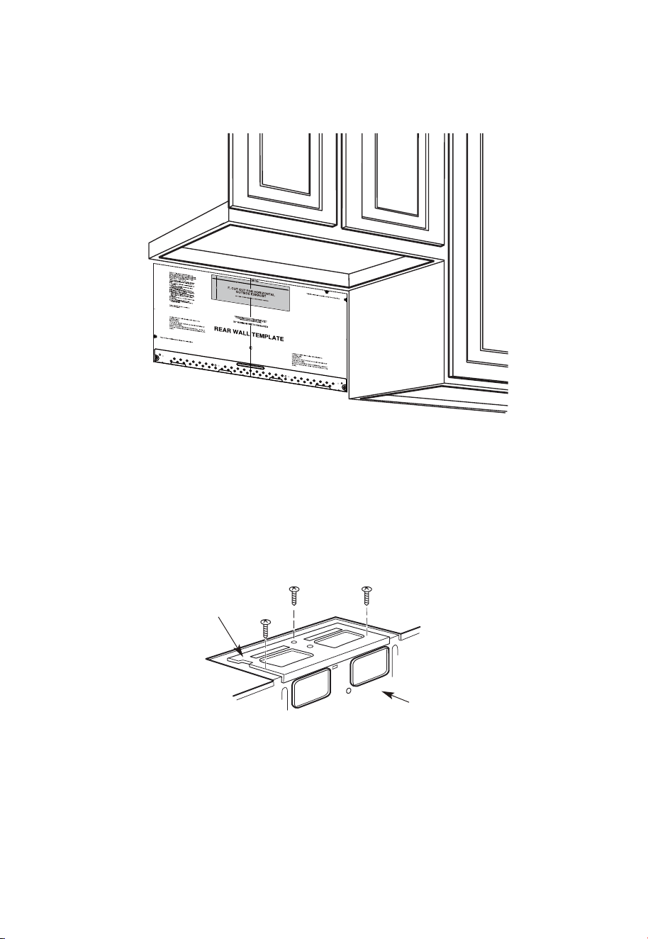
FR-36
B1. PRÉPARATION DE LA PAROI ARRIÈRE POUR L'ÉCHAPPEMENT ARRIÈRE
EXTÉRIEUR
Vous devez découper une ouverture dans la paroi arrière pour l'échappement extérieur.
1. Lisez les consignes relatives au MODÈLE DE MUR ARRIÈRE. Collez-le au mur arrière.
2. Découpez l'ouverture en suivant les consignes relatives au MODÈLE DE MUR
ARRIÈRE.
B2. RETIRER LA PLAQUE DU SOUFFLEUR
Retirez et conservez la vis qui maintient la plaque du souffleur au micro-ondes. Soulevez
la plaque du souffleur.
Plaque de soufflage
Arrière du
micro-ondes
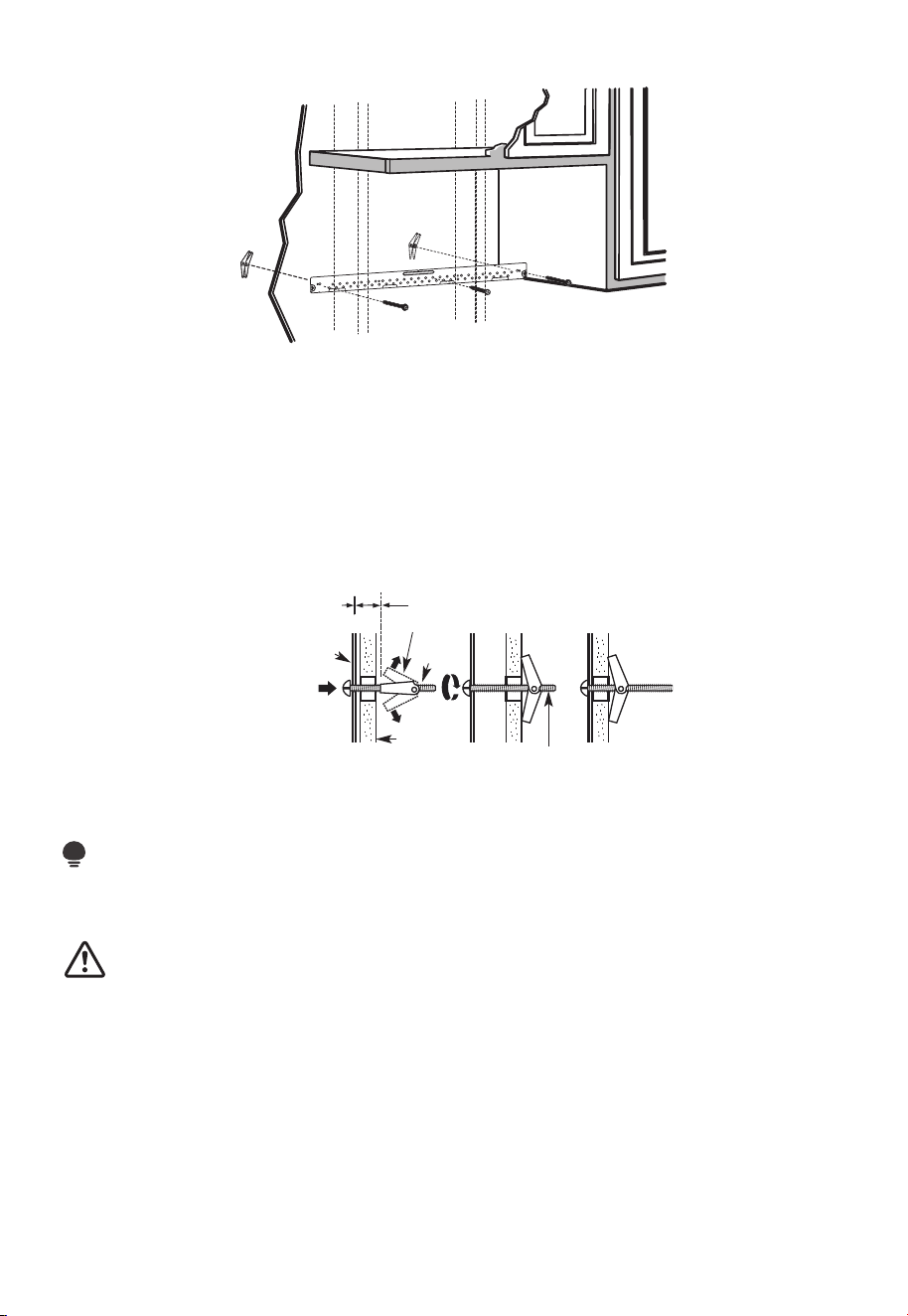
FR-37
B3. FIXEZ LA PLAQUE DE MONTAGE AU MUR
Fixez la plaque au mur à l'aide de boulons à genouillère. Au moins une vis à bois doit être
utilisée pour fixer la plaque à un poteau mural.
1. Retirez les ailettes à genouillère des boulons.
2. Insérez les boulons dans la plaque de montage à travers les trous destinés à pénétrer
dans la cloison sèche et fixez à nouveau les ailettes à genouillère à 3⁄4po (19 mm) sur
chaque boulon.
Pour utiliser les boulons à genouillère :
Plaque de
montage
Espacement pour les
bascules de plus de
l'épaisseur du mur
Ailettes à genouillère
Boulon à
genouillère
Mur
Extrémité du boulon
3. Placez la plaque de montage contre le mur et insérez les ailettes à genouillère dans
les trous du mur pour monter la plaque.
REMARQUE :
Avant de serrer les boulons à genouillère et la vis à bois, assurez-vous que le bas de la
plaque de montage touche le bas de l'armoire lorsqu'il est poussé contre le mur et que la
plaque est correctement centrée sous l'armoire.
MISE EN GARDE:
Veillez à éviter de pincer les doigts entre l'arrière de la plaque de montage et le mur.
4. Serrez tous les boulons. Retirez la plaque du mur pour aider à serrer les boulons.
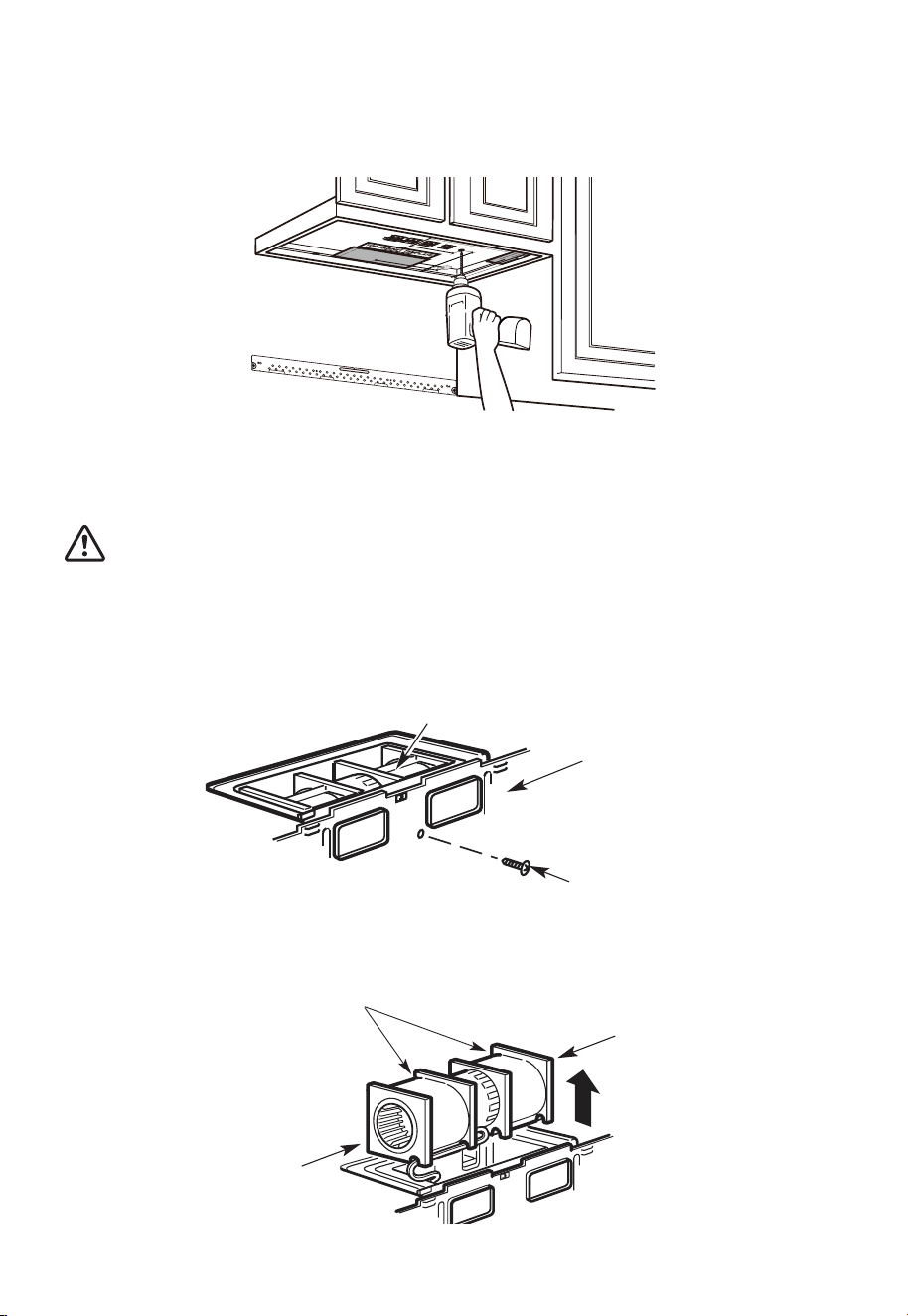
FR-38
B4. UTILISER LE MODÈLE D'ARMOIRE SUPÉRIEURE POUR LA PRÉPARATION
DE L'ARMOIRE SUPÉRIEURE
Vous devez percer des trous pour les vis du support supérieure et un trou suffisamment
grand pour que le cordon d'alimentation s'y insère.
1. Lisez les consignes relatives au MODÈLE D'ARMOIRE SUPÉRIEUR.
2. Collez-le sous l'armoire supérieure.
3. Percez les trous en suivant les consignes relatives au MODÈLE D'ARMOIRE SUPÉRIEUR.
MISE EN GARDE:
Portez des lunettes de sécurité lorsque vous percez des trous dans le fond de l'armoire.
B5. ADAPTATION DU SOUFFLEUR À MICRO-ONDES POUR L'ÉCHAPPEMENT
ARRIÈRE EXTÉRIEUR
1. Retirez et conservez la vis qui maintient le moteur du souffleur au micro-ondes.
Moteur du souffleur
Arrière du
micro-ondes
Vis du moteur
du souffleur
2. Retirez délicatement l'unité de soufflage. Les câbles s'étendront suffisamment loin
pour vous permettre de régler l'unité de soufflage.
Avant : Ouvertures des
pales de ventilateur
orientées vers l'avant
Extrémité B
Extrémité A
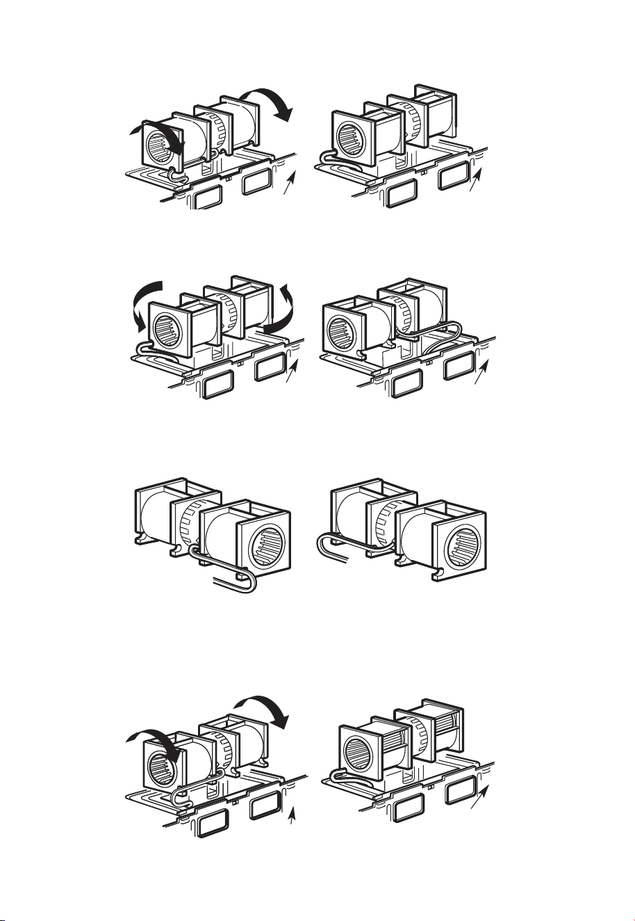
FR-39
3. Faites rouler l'unité de soufflage à 90°
Avant la rotation Après la rotation
Arrière du
micro-ondes
Arrière du
micro-ondes
4. Tournez l'unité de soufflage dans le sens inverse des aiguilles d'une montre à 180°.
Avant la rotation Après la rotation
Arrière du
micro-ondes
Arrière du
micro-ondes
5. Retirez délicatement les câbles des rainures. Réacheminez les câbles à travers les
rainures de l'autre côté de l'unité de soufflage.
Avant le réacheminement
Après le réacheminement
Câbles acheminés
par le côté droit
Câbles acheminés
par le côté gauche
6. Tournez l'unité de soufflage de 90° de sorte que les ouvertures des pales du
ventilateur soient tournées vers l'arrière du micro-ondes.
Avant le roulage Après le roulage
Arrière du
micro-ondes
Arrière du
micro-ondes
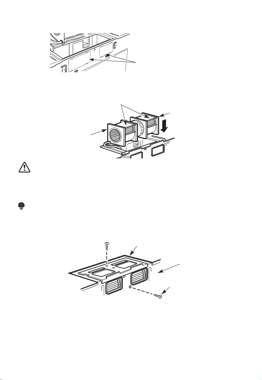
FR-40
7. Retirez les plaques défonçables à l'arrière de l'appareil à l'aide des pinces à découper.
(pour certains modèles)
Plaques de déblocage :
Coupez les 4 toiles sur chaque
panneau de déblocage et retirez
les déblocages métalliques pour le
flux d'air arrière. Veuillez prendre
soin d'enlever les bords tranchants
créés par le retrait des plaques de
déblocage.
Arrière du micro-ondes
8. Replacez l'unité de soufflage dans l'ouverture.
APRÈS : Ouvertures
des pales de ventilateur
orientées vers l'arrière
Extrémité B
Extrémité A
MISE EN GARDE:
Ne tirez ni n'étirez le câblage de l'unité de soufflage. Assurez-vous que les câbles ne sont
pas pincés et qu'ils sont correctement fixés.
REMARQUE :
Les ouvertures d'échappement de l'unité de soufflage doivent correspondre aux
ouvertures d'échappement à l'arrière du four à micro-ondes.
9. Fixez l'unité de soufflage au micro-ondes avec la vis d'origine.
Plaque de soufflage
Arrière du
micro-ondes
Vis du moteur
du souffleur
10. Remettez la plaque du souffleur dans la même position qu'auparavant avec la vis.
Assurez-vous que la vis est bien serrée.
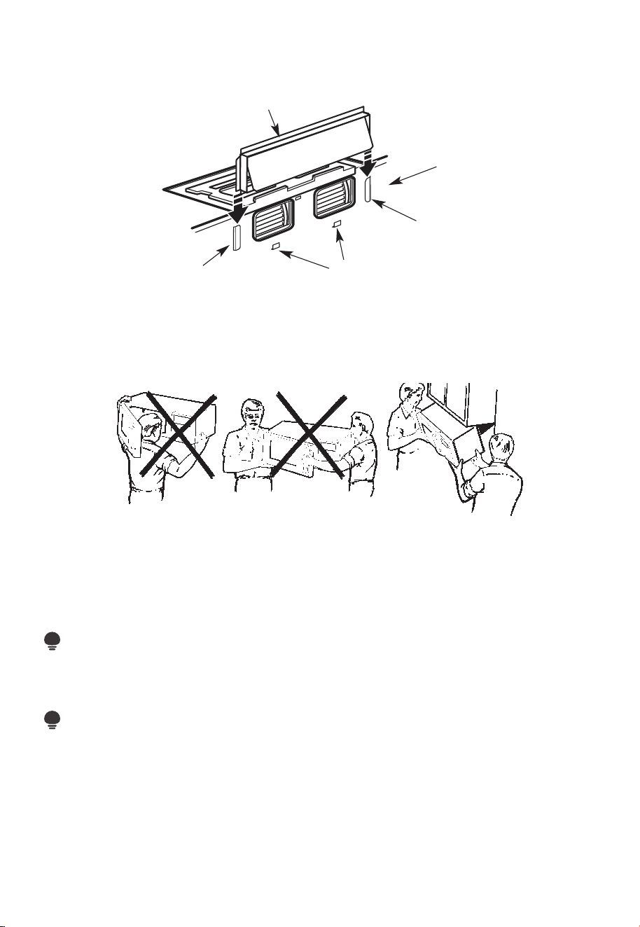
FR-41
11. Fixez l'adaptateur d'échappement à l'arrière du four en le glissant dans les guides
situés en haut au centre de l'arrière du four.
Adaptateur
Arrière du
micro-ondes
Guide
Onglets de verrouillage
Guide
Poussez fermement jusqu'à ce qu'il soit dans les languettes de verrouillage inférieures.
Veillez à ce que la charnière de l'amortisseur soit installée de manière à ce qu'elle soit en
haut et que l'amortisseur oscille librement.
B6. MONTER LE FOUR À MICRO-ONDES
POUR FACILITER L'INSTALLATION ET PROCURER LA SÉCURITÉ PERSONNELLE,
NOUS VOUS RECOMMANDONS QUE DEUX PERSONNES INSTALLENT CE FOUR À
MICRO-ONDES.
IMPORTANT : Ne saisissez pas et n'utilisez pas la poignée ou le bouclier thermique
pendant l'installation. Ne retirez pas les entretoises en carton entre le bouclier thermique
et la porte.
REMARQUE :
Si votre armoire est en métal, utilisez l'œillet en nylon autour du trou du cordon
d'alimentation pour éviter de couper celui-ci.
REMARQUE :
Nous vous recommandons d'utiliser des blocs de remplissage de la façade de l'armoire
suspendus sous l'étagère inférieure de celle-ci.
IMPORTANT : Si les blocs de remplissage ne sont pas utilisés, des vis de serrage
excessives peuvent endommager le boîtier.
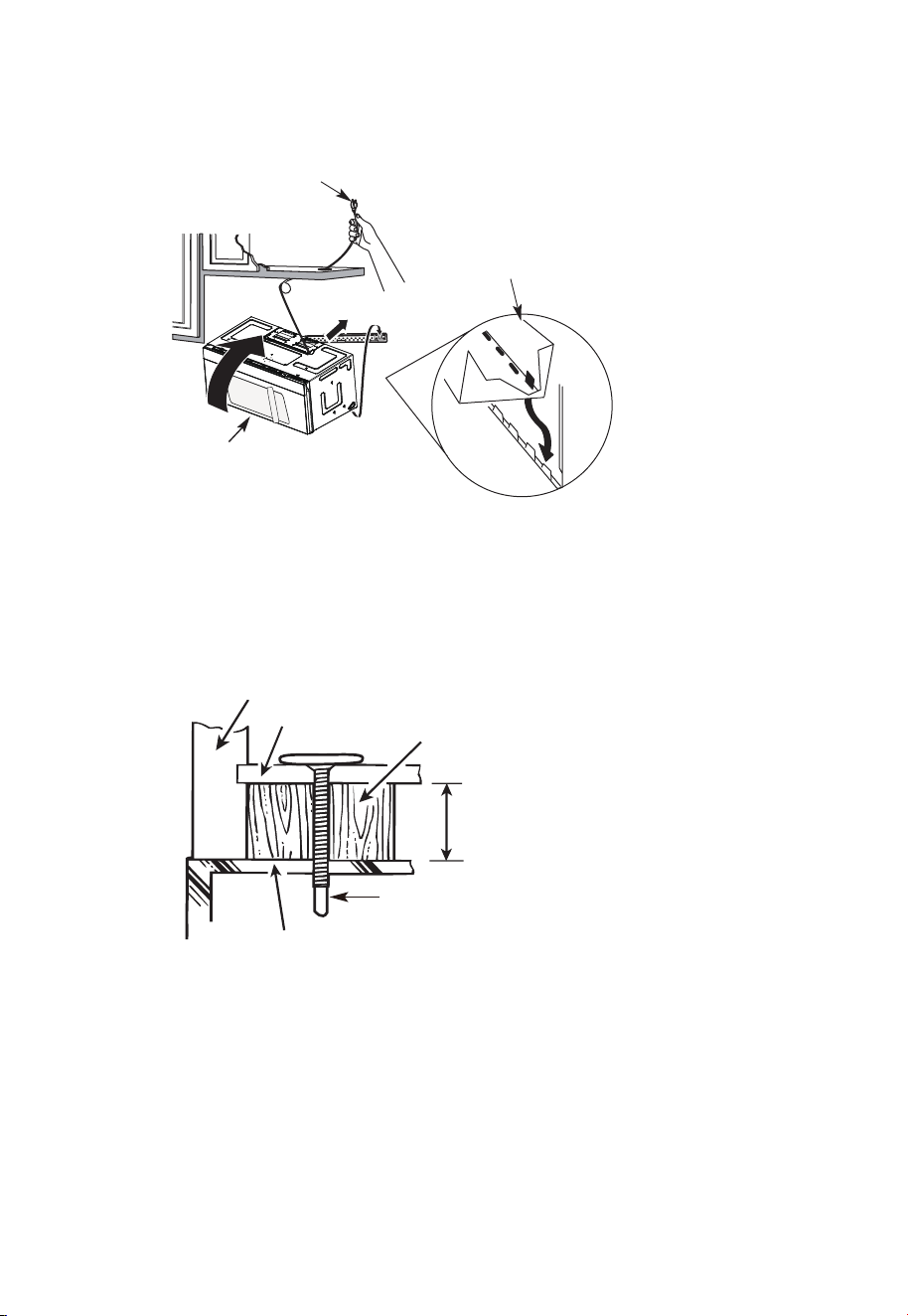
FR-42
REMARQUE : Lors du montage du four à
micro-ondes, enfilez le cordon d'alimentation
à travers le trou situé au bas de l'armoire
supérieure. Gardez-la bien serrée tout au
long des étapes 1 à 3. Ne pincez pas le
cordon ou ne soulevez pas le four en tirant
sur le cordon.
1. Soulevez le micro-ondes, inclinez-le
vers l'avant et accrochez les fentes
du bord inférieur arrière sur quatre
languettes inférieures de la plaque
de montage.
2. Tournez l'avant du
four contre le fond de
l'armoire.
3. Insérez la vis à alignement automatique à travers le trou central supérieur de l'armoire.
Fixez temporairement le four en tournant la vis d'au moins deux tours complets après
l'engagement des fils (elle sera complètement serrée plus tard). Assurez-vous de
garder le cordon d'alimentation serré. Veillez à ne pas pincer le cordon, en particulier
lors du montage affleurant au bas de l'armoire.
Façade de l'armoire
Étagère inférieure de l'armoire
Bloc de
remplissage
Équivalent à la profondeur de
l'encastrement de l'armoire
Vis à alignement automatique
Dessus du four à micro-ondes
4. Fixez le four à micro-ondes à l'armoire supérieure.

FR-43
5. Insérez 2 vis à alignement automatique
à travers les trous extérieurs de
l'armoire supérieure. Tournez deux
tours complets sur chaque vis.
6. Serrez les deux vis extérieures au sommet du four à micro-ondes. (Tout en serrant les
vis, maintenez le four à micro-ondes en place contre le mur et l'armoire supérieure.)
7. Installez des filtres à graisse. Consultez le Guide relatif à l'utilisation et l'entretien
fourni avec le micro-ondes pour plus d'informations.
C. RECIRCULATION (sans conduit de ventilation)
APERÇU DE L'INSTALLATION
C1. Fixez la plaque de montage au mur
C2. Préparez l'armoire supérieure
C3. Vérifiez la plaque du souffleur
C4. Monter le four à micro-ondes
C5. Installez ou changez le filtre à charbon
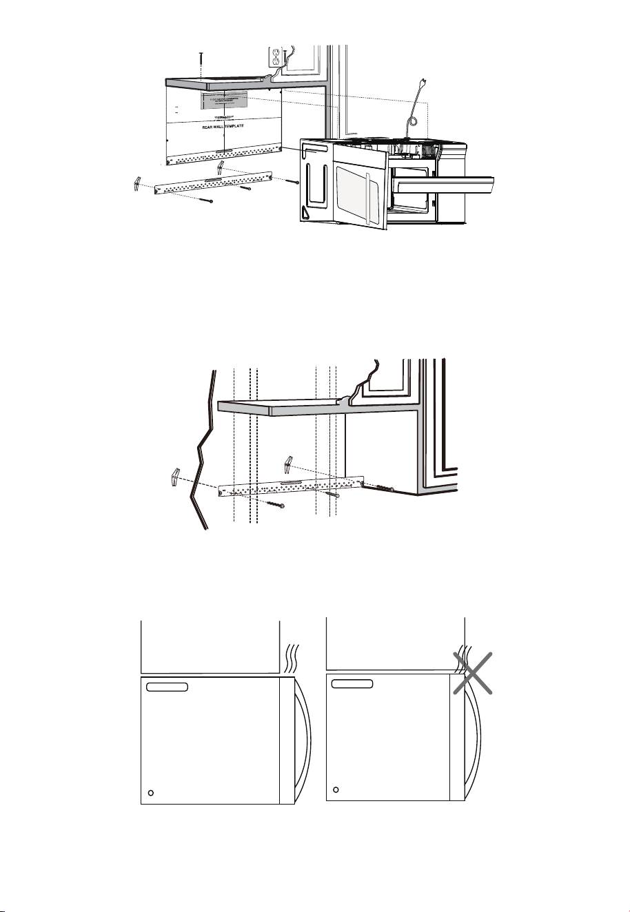
FR-44
12
"
4"
R
NO
E
A
T
D
E
:
A
IT
N
I
D F
S
VE
O
L
R
L
Y
O
I
W
MP
T
O
HE
R
T
D
A
I
R
N
E
T
C
T
TI
O
O
I
N T
H
E
IN
ST
AL
LAT
I
O
N I
NSTR
U
CTI
O
N
N
S
S
BEF
O
RE
PR
O
C
EE
D
I
NGW
I
T
H
T
H
IS
R
E
AR W
ALL
TE
M
PL
A
T
E
.
T
e
mp
l
a
te
serve
s
t
o
p
mo
t
U
u
le
s
n
t
e
.
t
i
1
o
.
u
Th
is
Re
n
a
g
r
p
l
W
a
a
te
ll
an
d to
l
o
ca
t
h
t
e e h
o
r
iz
o
o
sit
n
t
i
o
a
l
n
e
t
x
h
h
e
a
b
us
ot
t
t
o
m
e
to
c
h
e
c
k
th
a
t
t
h
e
t
e
mp
lat
e
i
s
p
o
sit
ion
d
L
oc
o
u
nt
i
n
ANT:
I
m
M
P
O
R
T
E
AT
L
at
ea
g
n
d
pla
m
te
a
.
rk
ho
les to
a
li
g
n
w
it
h
h
ol
e
s
i
n
t
h
e
LOCA
T
N
TERL
E
I
N
AS
E.
T
O
NE
S
TU
D
O
N
EI
TH
E
R
SID
E
OF
T
H
E
C
E
HEL
O
CA
TI
SP
ACE
AR
EA.
MARK
T
D TO
GGLE
B
O
O
L
N F
TS
O
I
R
N
2
T
A
H
D
E
DI
M
T
O
IO
U
N
N
T
AL
I
N
,
E
G
V
P
E
L
N
AT
L
Y
E
oun
t
i
n
:
L
o
ca
t
e
a
g
nd
p
lat
ma
e
.
rk
ho
les
t
o
a
l
i
gn
w
i
t
h
h
o
l
e
s
i
n
t
h
e
I
m
MPO
RT
E
A
N
A
T
T
L
LO
C
AT
NT
E
RL
E
I
A
NE
ST
.
O
NE
STUD
O
N
EI
TH
ER SIDE
O
F
THECE
H
E
LOCA
T
I
SP
AC
AREA.
MAR
K
E
D
T
T
OG
G
LE
B
O
ON
F
L
TS
O
R
IN
2
T
A
H
D
E
DIT
MO
I
O
U
N
N
A
TI
L
,
N
E
G
VE
P
LA
NL
T
Y
E
T
r
im
the
rear
w
a
ll te
mp
lat
e
a
l
on
g
the
d
o
tted
l
i
n
e.
3
/8"
T
OEDG
E
Trim t
he rear wa
l
l t
e
m
pla
t
e along
t
h
e d
ot
t
e
d l
in
e.
L
a
o
c
c
c
a
u
a
t
r
e
a
t
l
e
v
a
el
n
y
e
d
.
l
2.
ma
r
k a
t
le
a
s
t o
n
e
stud
onthe
l
e
f
t
o
r
ri
g
h
t
s
i
de
o
f
th
e
ce
n
terl
i
ne
.
I
t a
t
rop
mi
s
i
n
t
to
u
s
e
a
t
l
eas
t
on
e wo
o
d
nt
w
e
a
v
d
f
e
i
.
rm
M
ly
a
r
i
k
n
t
a
w
s
o
t
u
a
d
dd
t
i
o
t
i
o
s
n
u
a
p
l
,
p
o
e
r
v
t
e
t
h
n
e
ly
w
s
p
ei
a
gh
ce
t
d
o
o
r
s
i
th
nt
e s
h
u
e
p
m
p
l
a
i
r
ed
ke
t
d
o
l
g
o
g
c
l
a
e
t
b
io
o
l
n
t
s
s
.
.
W
h
ere
t
he
r
ei
s
l
s
3
o
f
o
.
c
r
c
t
t
t
a
D
a
e
h
h
o
t
r
i
e
s
w
g
a
i
l
o
t
t
l
g
u
n
m
l
m
d
ho
d
s
i
e
o
o
,
c
r
f
l
u
d
e
rilla
3/16"
h
ol
e
f
or
w
o
o
d
s
c
r
ew
s
.
F
orho
l
es
n ne u
p
w
it
h
a
s
t
ud
,
d
rill5
/8
"h
ol
esf
o
ro
l
t
t
N
s.
l
i
OD
b
o
T
I
NSTAL
L
T
H
E
MOU
N
T
I
N
GPL
A
TE
AT
R
T
HI
m
S
v
e
T
I
O
M
E
.
4
.
e
o
t
h
e
te
mp
la
t
e
f
r
o
m
th
e re
a
r
w
a
l
l.
5
.
R
e
vie
wt
h
e
Inst
all
a
t
i
o
n
In
s
t
ruct
i
o
n
b
ook
f
or
y
o
u
r
i
n
sta
ll
a
t
ion
s
i
tu
a
ti
o
n.
Da
r
le
v
uel
ta
al
a
ho
ja
par
aco
n
sult
a
r
l
a
v
e
r
s
ió
n
e
nEs
p
a
ñ
o
l
.
REMARQUES IMPORTANTES :
1. Assurez-vous que les vis du moteur du souffleur et de la plaque du souffleur sont bien
serrées lors de leur réinstallation. Cela aidera à éviter les vibrations excessives.
2. Assurez-vous que le câblage du moteur a été correctement acheminé et sécurisé et
que les câbles ne sont pas pincés.
C1. FIXEZ LA PLAQUE DE MONTAGE AU MUR
Fixez la plaque au mur à l'aide de boulons à genouillère. Au moins une vis à bois doit être
utilisée pour fixer la plaque à un poteau mural.
Si la profondeur de l'armoire, y compris les portes de l'armoire, est supérieure à 13po,
l'unité doit être espacée du mur à l'aide de matériaux adéquats prenant en charge 150 lb
pour permettre un échappement/admission d'air par le haut appropriée.
Armoire
Armoire
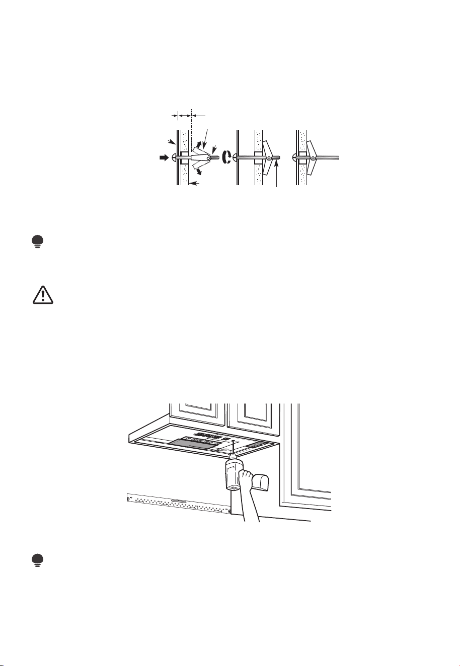
FR-45
1. Retirez les ailettes à genouillère des boulons.
2. Insérez les boulons dans la plaque de montage à travers les trous destinés à entrer
dans la cloison sèche et fixez à nouveau les ailettes à genouillère de 3/4po à (19 mm)
sur chaque boulon.
Pour utiliser les boulons à genouillère:
Plaque de
montage
Espacement pour les
bascules de plus de
l'épaisseur du mur
Ailettes à genouillère
Boulon à
genouillère
Mur
Extrémité du boulon
3. Placez la plaque de montage contre le mur et insérez les ailettes à genouillère dans
les trous du mur pour monter la plaque.
REMARQUE :
Avant de serrer les boulons à genouillère et la vis à bois, assurez-vous que le bas de la
plaque de montage touche le bas de l'armoire lorsqu'il est poussé contre le mur et que la
plaque est correctement centrée sous l'armoire.
MISE EN GARDE:
Veillez à éviter de pincer les doigts entre l'arrière de la plaque de montage et le mur.
4. Serrez tous les boulons. Retirez la plaque du mur pour aider à serrer les boulons.
C2. UTILISER LE MODÈLE D'ARMOIRE SUPÉRIEURE POUR LA PRÉPARATION
DE L'ARMOIRE SUPÉRIEURE
Vous devez percer des trous pour les vis de support supérieures et un trou suffisamment
grand pour que le cordon d'alimentation s'y insère.
1. Lisez les consignes relatives au MODÈLE D'ARMOIRE SUPÉRIEUR.
2. Collez-le sous l'armoire supérieure.
REMARQUE :
Réglez le modèle supérieur en conséquence si le micro-ondes est espacé du mur en
raison de la profondeur de l'armoire (y compris les portes d'armoire) de plus de 13po.
Percez les trous en suivant les consignes relatives au MODÈLE D'ARMOIRE SUPÉRIEUR.
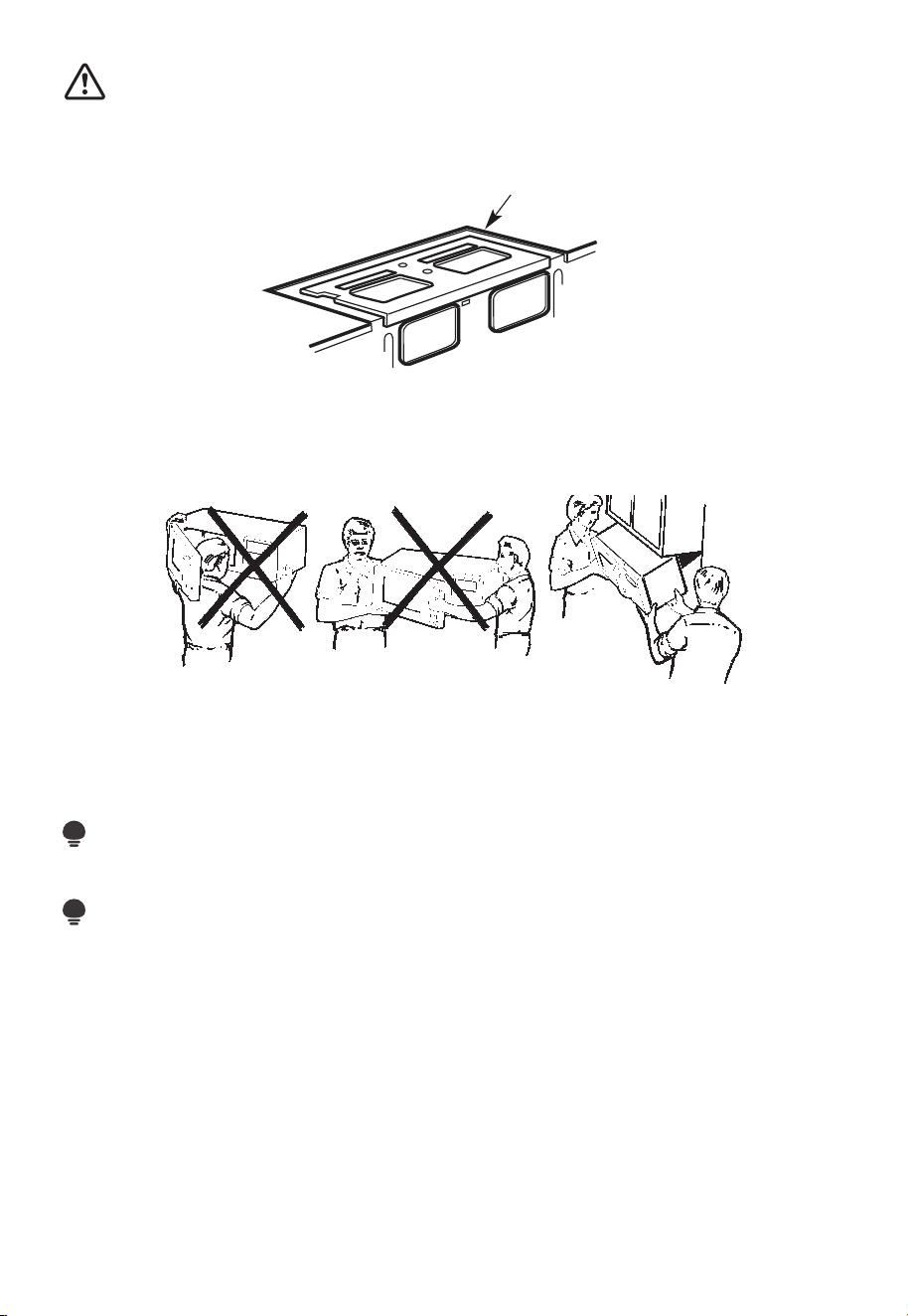
FR-46
MISE EN GARDE:
Portez des lunettes de sécurité lorsque vous percez des trous dans le fond de l'armoire.
C3. VÉRIFIEZ LA PLAQUE DU SOUFFLEUR
Plaque de soufflage
Placez le micro-ondes en position verticale, avec la partie supérieure de l'appareil
orientée vers le haut. Vérifiez que la plaque du souffleur est correctement installée sur
l'appareil.
C4. MONTER LE FOUR À MICRO-ONDES
POUR FACILITER L'INSTALLATION ET PROCURER LA SÉCURITÉ PERSONNELLE, NOUS
VOUS RECOMMANDONS QUE DEUX PERSONNES INSTALLENT CE FOUR À MICRO-
ONDES.
IMPORTANT : Ne saisissez pas et n'utilisez pas la poignée ou le bouclier thermique
pendant l'installation. Ne retirez pas les entretoises en carton entre le bouclier thermique
et la porte.
REMARQUE :
Si votre armoire est en métal, utilisez l'œillet en nylon autour du trou du cordon
d'alimentation pour éviter de couper celui-ci.
REMARQUE :
Nous vous recommandons d'utiliser des blocs de remplissage si la façade de l'armoire
est suspendue sous l'étagère inférieure de celle-ci.
IMPORTANT : Si les blocs de remplissage ne sont pas utilisés, un endommagement du
boîtier peut survenir à cause de vis de serrage excessives.
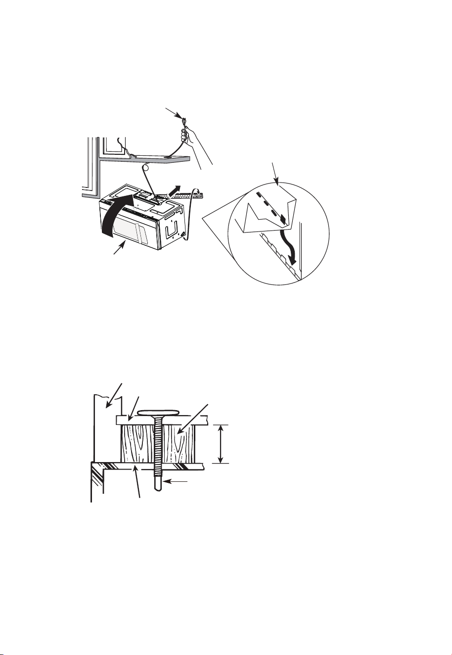
FR-47
REMARQUE : Lors du montage du
four à micro-ondes, enfilez le cordon
d'alimentation à travers le trou situé au
bas de l'armoire supérieure. Gardez-la bien
serrée tout au long des étapes 1 à 3. Ne
pincez pas le cordon ou ne soulevez pas le
four en tirant sur le cordon.
1. Soulevez le micro-ondes,
inclinez-le vers l'avant et
accrochez les fentes du bord
inférieur arrière sur quatre
languettes inférieures de la
plaque de montage.
2. Tournez l'avant du four
contre le fond de l'armoire.
3. Insérez une vis à alignement automatique dans le trou central supérieur de l'armoire.
Fixez temporairement le four en tournant la vis d'au moins deux tours complets après
l'engagement des fils (Il sera complètement serré plus tard.) Assurez-vous de garder
le cordon d'alimentation serré. Veillez à ne pas pincer le cordon, en particulier lors du
montage affleurant au bas de l'armoire.
Façade de l'armoire
Étagère inférieure de l'armoire
Bloc de remplissage
Équivalent à la profondeur de
l'encastrement de l'armoire
Vis à alignement automatique
Dessus du four à micro-ondes
4. Fixez le four à micro-ondes à l'armoire supérieure.
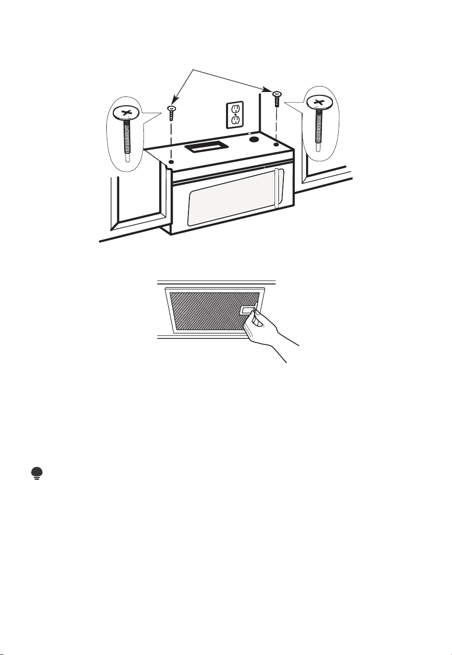
FR-48
5. Insérez 2 vis à alignement automatique à
travers les trous extérieurs de l'armoire
supérieure. Tournez deux tours complets
sur chaque vis.
6. Serrez les deux vis extérieures au sommet du four à micro-ondes. (Tout en serrant les
vis, maintenez le four à micro-ondes en place contre le mur et l'armoire supérieure.)
7. Installez des filtres à graisse. Voir le guide relatif à l'utilisation et à l'entretien emballé
avec le micro-ondes.
C5. INSTALLATION OU CHANGEMENT DU FILTRE À CHARBON (certains
modèles)
REMARQUE :
Le filtre à charbon est installé en usine dans certains modèles. Reportez-vous au Guide
d'utilisation et d'entretien pour voir si le vôtre est installé en usine et pour obtenir des
informations sur le remplacement.
Pour les modèles sans porte d'accès au filtre de recirculation, suivez les étapes suivantes
pour remplacer ou installer un filtre à charbon :
1. Débranchez le four à micro-ondes ou débranchez l'alimentation.
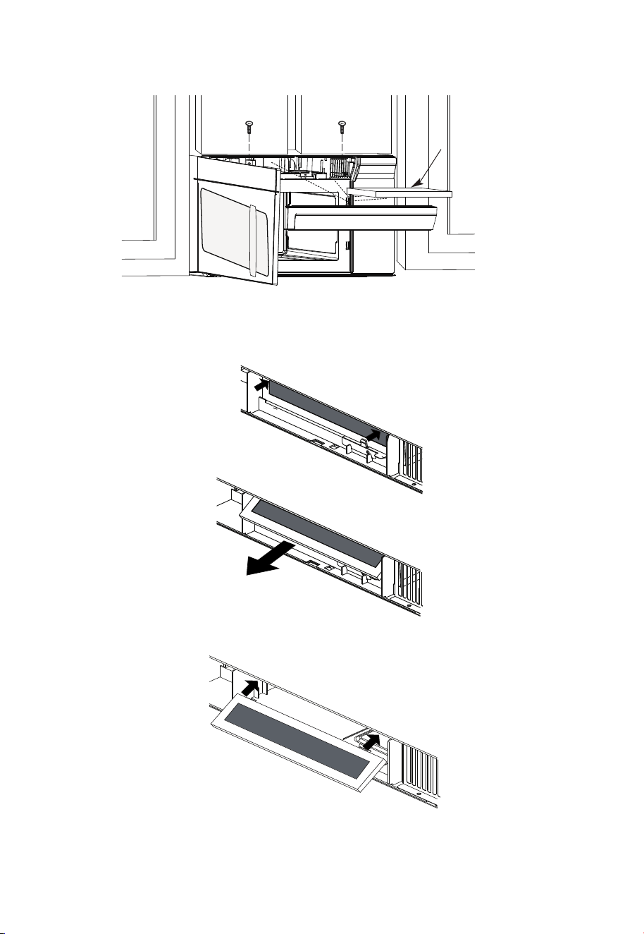
FR-49
2. Ouvrez la porte du four à micro-ondes et retirez les deux vis de fixation de l'évent
situées sur le dessus du four à micro-ondes à l'aide d'un tournevis Phillips n°1.
Filtre à
charbon
3. Retirez le filtre à charbon en poussant le haut de celui-ci vers l'intérieur, puis tirez-le
vers l'avant hors de l'appareil.
4. Faites glisser le haut du nouveau filtre à charbon dans le haut de la cavité du filtre.
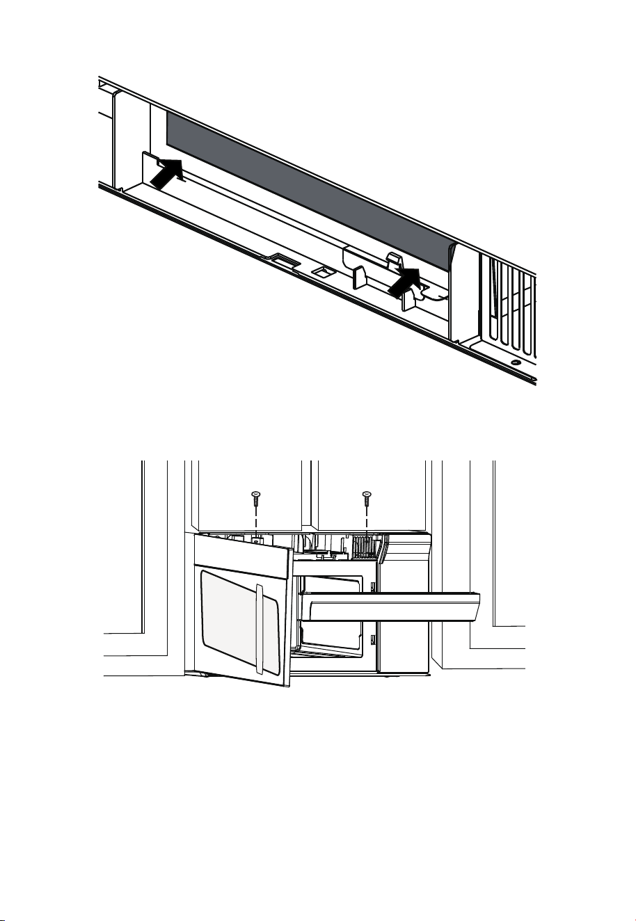
FR-50
5. Appuyez sur le bas du filtre à charbon pour le placer dans la bonne position.
6. Réinstallez l'évent en faisant glisser le fond de celui-ci en place. Poussez le haut de
l'évent en position et glissez-le en place. Remplacez les deux vis de fixation de l'évent
situées sur le dessus du micro-ondes à l'aide d'un tournevis Phillips n°1.
7. Fermez la porte du micro-ondes. Branchez le four à micro-ondes ou rebranchez
l'alimentation.
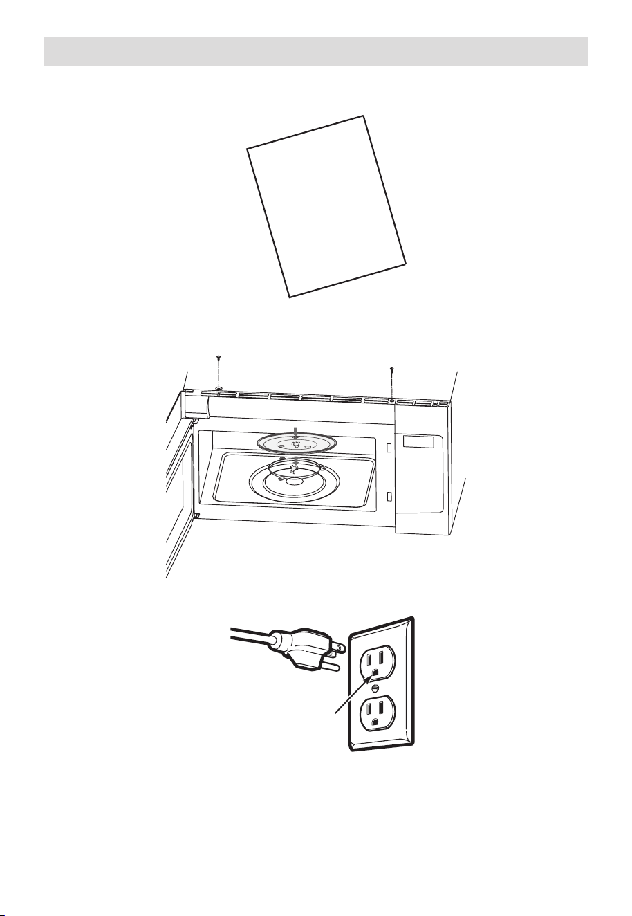
FR-51
Avant d'utiliser votre micro-ondes
1. Assurez-vous que le four à micro-ondes a été installé conformément aux consignes.
USER
MANUAL
2. Retirez tout le matériel d'emballage du four à micro-ondes.
3. Installez l'écrou de la plaque tournante et du plateau en verre dans la cavité.
4. Branchez le cordon d'alimentation dans une prise électrique séparée et dédiée de 15 à
20 ampères.
Assurez-vous que
la mise à la terre
est correcte avant
l'utilisation
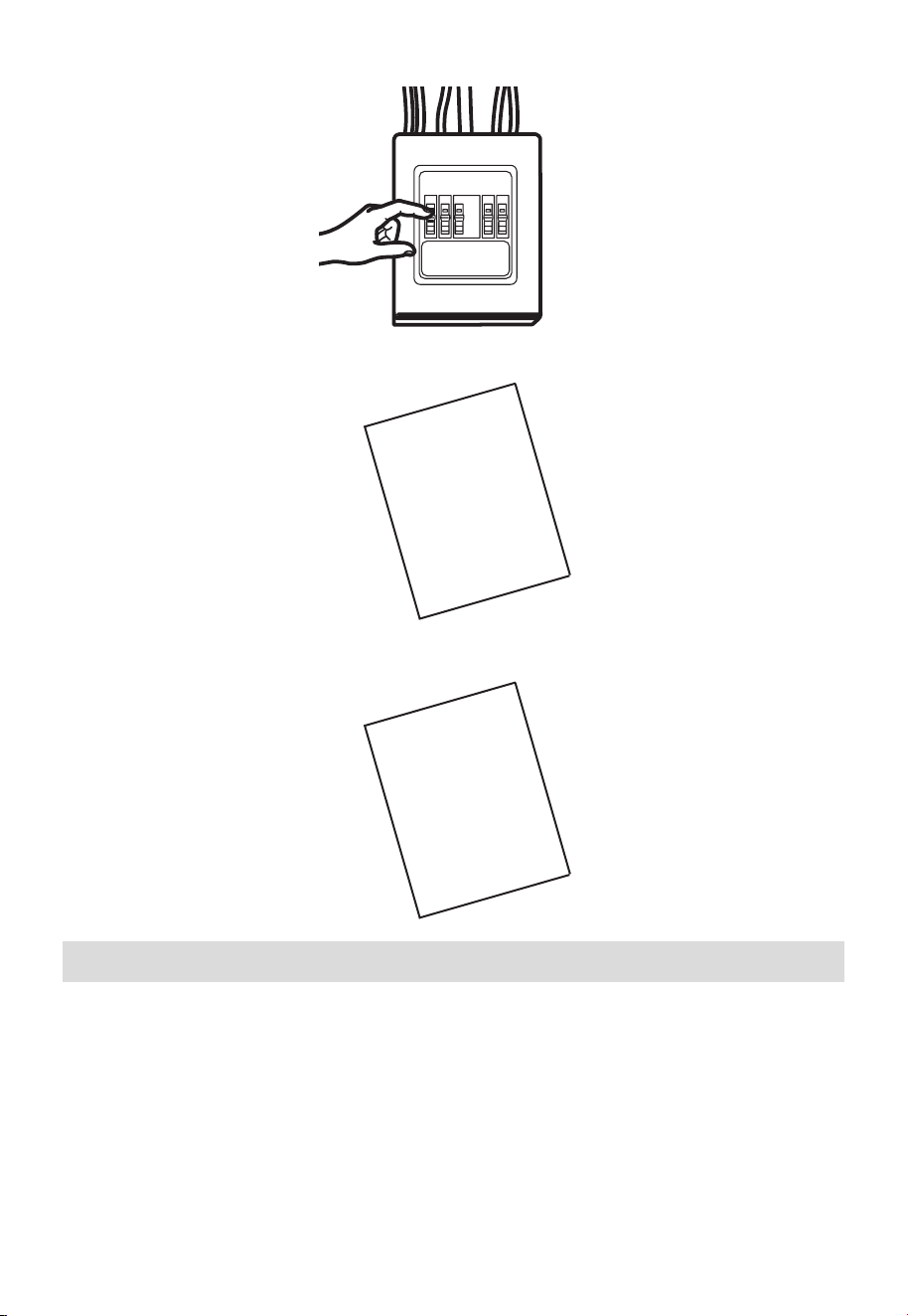
FR-52
5. Remplacez le fusible de la maison ou rallumez le disjoncteur.
6. Lisez le manuel d'utilisation.
USER
MANUAL
7. CONSERVEZ LE MANUEL D'UTILISATION POUR L'UTILISATION DE L'INSPECTEUR LOCAL.
USER
MANUAL
Contrôle de fonctionnement
1. Assurez-vous que l'appareil a été installé conformément à ces consignes.
2. Retirez tous les matériaux d'emballage du four.
3. Remplacez le fusible de la maison ou rallumez le disjoncteur.
4. Branchez le cordon d’alimentation dans la prise de courant.
5. Lisez les consignes d'utilisation avant de tester le produit.
6. Allumez le ventilateur d'échappement à la vitesse Turbo et confirmez qu'il fonctionne
à l'aide d'un mouchoir (il adhérera au filtre).
7. Vérifiez que le clapet d'échappement extérieur s'est ouvert.
8. Réglez le four à micro-ondes pendant 1 minute et confirmez que le four fonctionne
normalement à l'aide d'une tasse d'eau.
9. Conservez ces consignes d'installation à l'intention de l'inspecteur local en électricité.
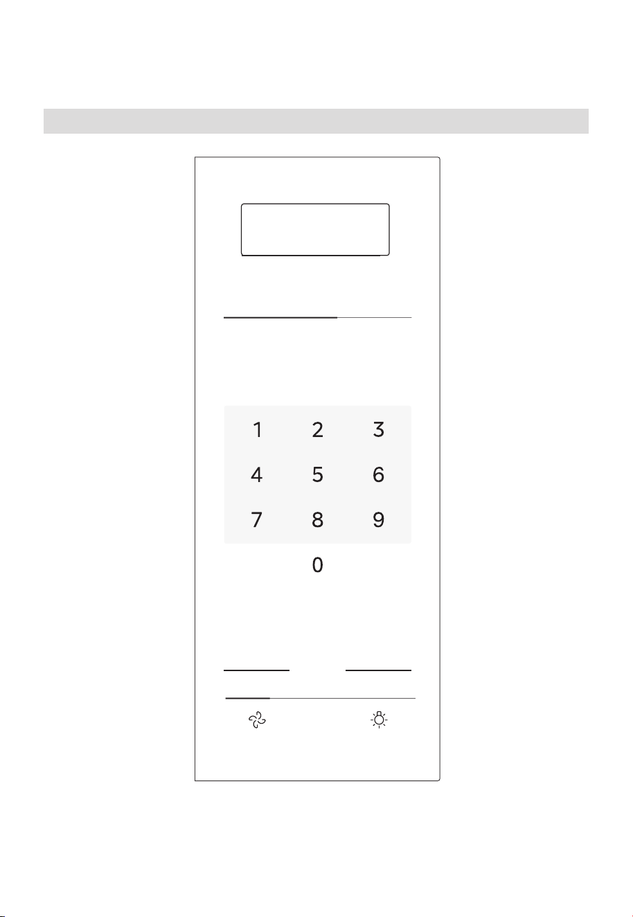
FR-53
CONSIGNES D'UTILISATION
Panneau de commande
CONSIGNES D'UTILISATION
Panneau de commande
FR-51
MENU AUTOMATIQUE ET PRÉRÉGLAGES
LÉGUMES POPCORN
POMME DE
TERRE
MENU DES
COLLATIONS
NIVEAU DE
PUISSANCE
ARRÊTER
EFFACER
DÉMARRER
+30 SEC.
MINUTERIE DÉCONGÉLATION
FONCTION
VENTILATEUR LAMPE
TEMPS DE
CUISSON
PRÉF.
UTILISATEUR
HORLOGE
FONDRE/
ADOUCIR
CUISSON RAPIDE
MENU
AUTOMATIQUE
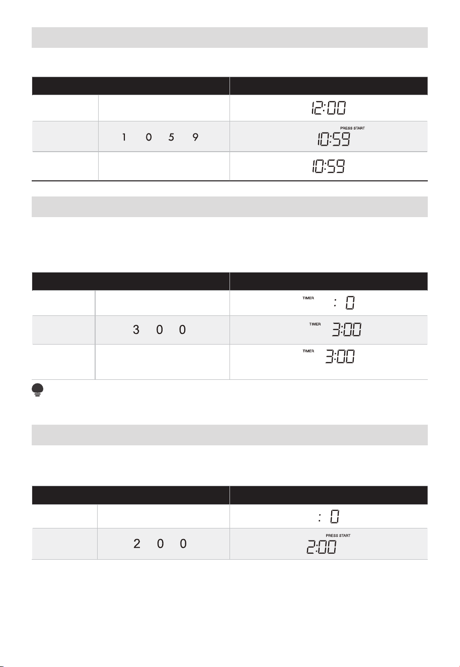
FR-54
Réglage de l’horloge
• Supposons que vous souhaitiez saisir l'heure correcte du jour 10:59.
TOUCHEZ L'ÉCRAN MONTRE :
1. HORLOGE
2.
3.
HORLOGE ou DÉMARRAGE
+ 30 SEC.
Réglage de la minuterie
Vous pouvez utiliser votre four à micro-ondes à l’aide d’un minuteur. Vous pouvez
configurer jusqu'à 99 minutes, 99 secondes. Le minuteur de cuisine peut être utilisé
pendant que le four à micro-ondes est en marche.
• Supposons que vous souhaitiez régler trois minutes.
TOUCHEZ L'ÉCRAN MONTRE :
1.
2.
3.
Compte à rebours
REMARQUE
Il n'y a pas d'autres programmes pendant la minuterie de la cuisine.
Micro-ondes
Votre four à micro-ondes peut être programmé pour 99 minutes 99 secondes (99:99).
Entrez toujours les secondes après les minutes, même si elles sont toutes les deux nulles.
• Supposons que vous souhaitiez cuire pendant 2 minutes à 90% de puissance
TOUCHEZ L'ÉCRAN MONTRE :
1. TEMPS DE CUISSON
2.
MINUTERIE
MINUTERIE
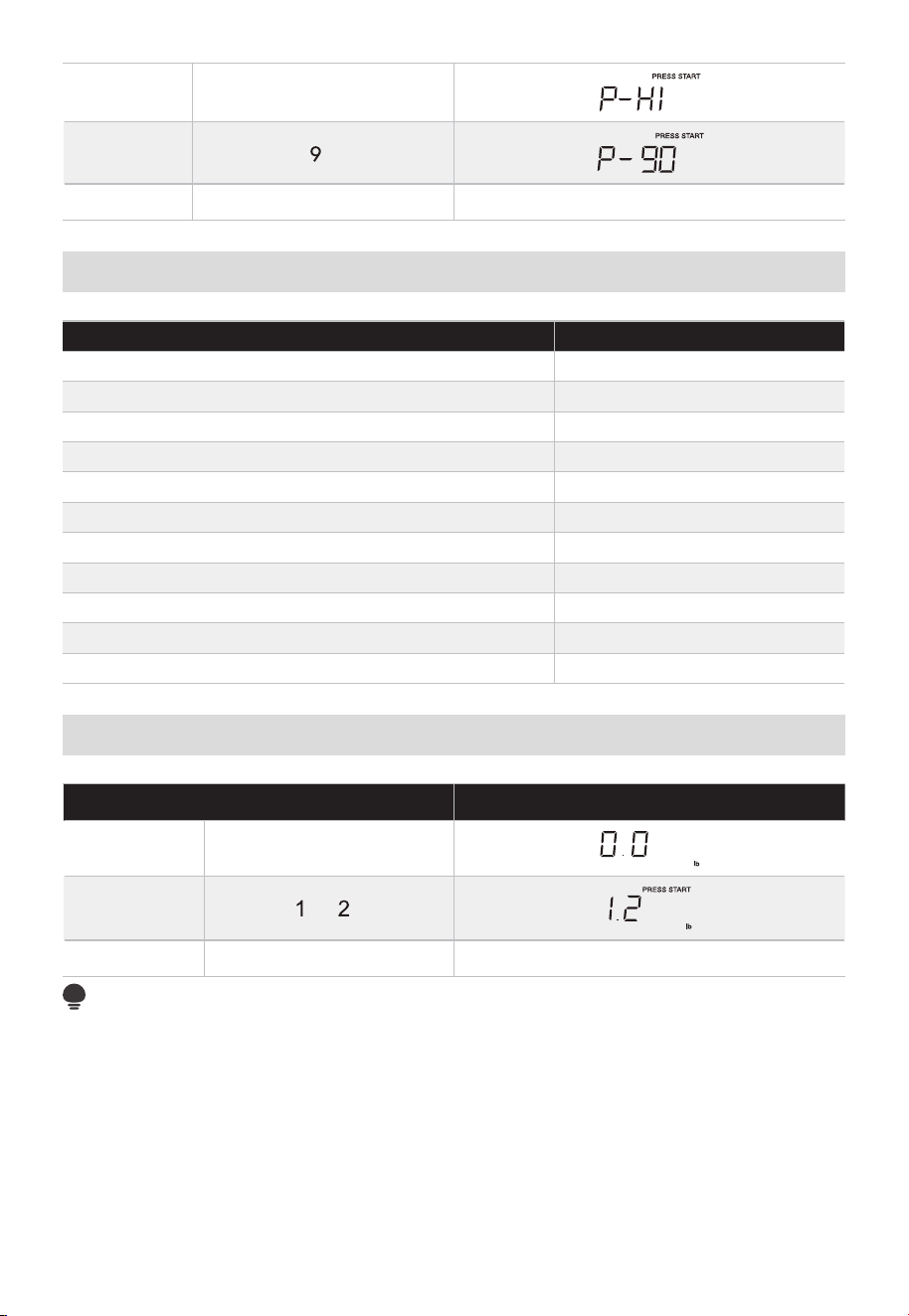
FR-55
3. NIVEAU DE PUISSANCE X 1
4.
5. DÉMARRER + 30 SEC. Compte à rebours
TABLEAU DES PUISSANCES
NIVEAU DE PUISSANCE Affichage
100% P-HI
90% P-90
80% P-80
70% P-70
60% P-60
50% P-50
40% P-40
30% P-30
20% P-20
10% P-10
0% P-0
Décongélation en fonction du poids
TOUCHEZ L'ÉCRAN MONTRE :
1. DÉCONGÉLATION x1
2.
3. DÉMARRER + 30 SEC. Compte à rebours
REMARQUE :
Le poids doit être une entrée valide pour que cette fonctionnalité puisse commencer.
Une saisie de poids valide est de 0,1 à 6,0 lbs.
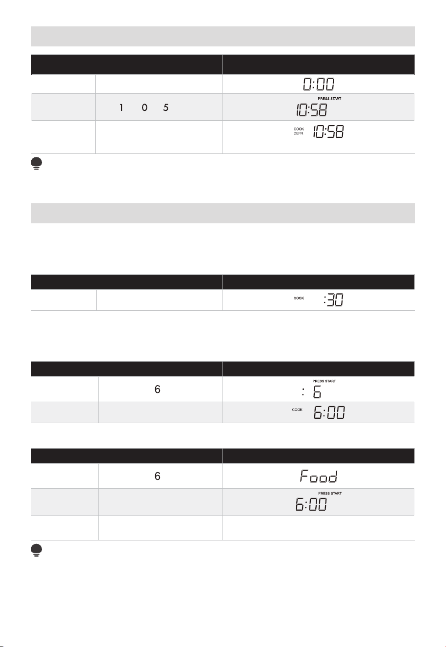
FR-56
Décongélation minutée
TOUCHEZ L'ÉCRAN MONTRE :
1. DÉCONGÉLATION x2
2.
8
3. DÉMARRER + 30 SEC.
Compte à rebours
REMARQUE :
L'avertisseur sonore retentira pour vous rappeler de retourner les aliments lorsque la
moitié du temps sera écoulé.
Cuisson rapide
1. Utilisation de l'option ajouter 30 secondes:
C’est une touche qui permet de gagner du temps. Il s’agit d’une fonction simplifiée vous
permettant de régler et de démarrer rapidement la cuisson au four à micro-ondes à 100%
de puissance.
TOUCHEZ L'ÉCRAN MONTRE :
1. DÉMARRER + 30 SEC.
2. Utilisation des pavés numériques pour «1-6»:
Appuyez sur les pavés numériques «1-6» pour commencer la cuisson avec le temps
correspondant pour un niveau de puissance de 100% directement. Par exemple, cuire
pendant 6 minutes pour un niveau de puissance de 100%.
TOUCHEZ L'ÉCRAN MONTRE :
1.
2. Après 2 secondes
La porte du four doit être ouverte et fermée 5 minutes avant la cuisson rapide, sinon, en
utiliser comme décrit ci-dessous.
TOUCHEZ L'ÉCRAN MONTRE :
1.
2. ouvrir la porte
3. DÉMARRER + 30 SEC.
Compte à rebours du temps (Fermez la
porte)
REMARQUE :
« Aliments » s'affiche si les touches numériques 1 à 6 ou « DÉMARRAGE + 30 SEC » ne
sont pas sélectionnées dans les 5 minutes suivant le placement de la nourriture dans
le four. Vous devez ouvrir puis refermer la porte pour effacer « Food » de l’écran. Puis
appuyez sur «DÉMARRAGE +30 SEC.» pour démarrer la cuisson.
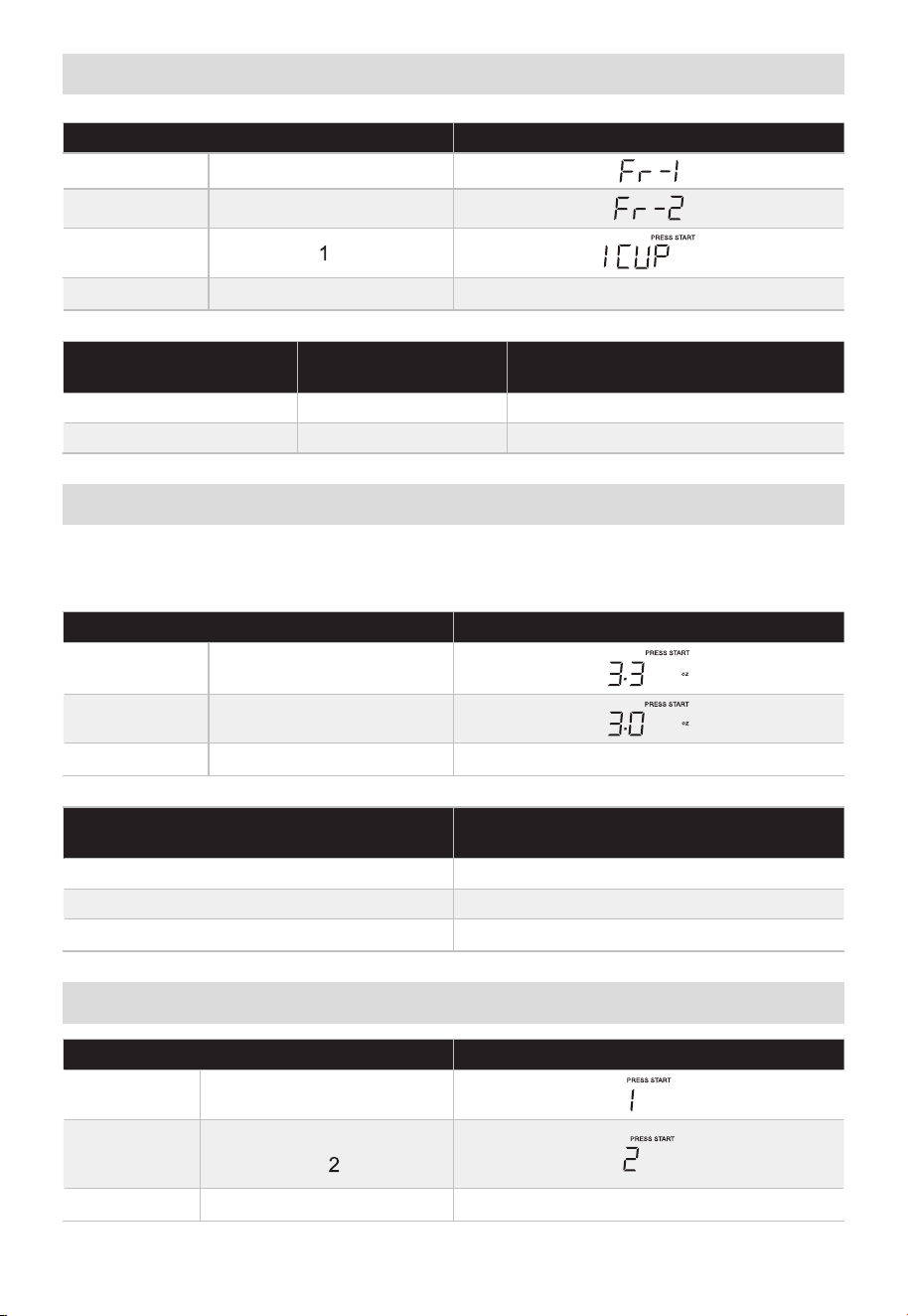
FR-57
Légumes
TOUCHEZ L'ÉCRAN MONTRE :
1. LÉGUMES X 1
2. LÉGUMES X 1
3.
4. DÉMARRER + 30 SEC.
Compte à rebours
APPUYEZ SUR LE
PAVÉ DE LÉGUMES
ALIMENT
TOUCHES
NUMÉRIQUE
MONTANT
x 1 Légumes frais 1, 2, 3, 4 1 - 4 tasses
x 2 Légumes surgelés 1, 2, 3, 4 1 - 4 tasses
Pop-corn
Appuyez sur la touche « POPCORN » et la LED affiche 3,3 onces. Appuyez sur
« POPCORN » à plusieurs reprises pour choisir le poids souhaité.
• Supposons que vous souhaitiez préparer 3,0 onces de popcorn.
TOUCHEZ L'ÉCRAN MONTRE :
1. POPCORN X 1
2. POPCORN X 1
3. DÉMARRER + 30 SEC.
Compte à rebours
APPUYEZ SUR LE PAVÉ POPCORN OU
SUR LES TOUCHES NUMÉRIQUES
MONTANT
x 1
x 2
x 3
Pomme de terre
TOUCHEZ L'ÉCRAN MONTRE :
1. POMME DE TERRE X 1
2.
POMME DE TERRE X 1
ou
3. DÉMARRER + 30 SEC.
Compte à rebours
3.3 oz
3.0 oz
1.75 oz
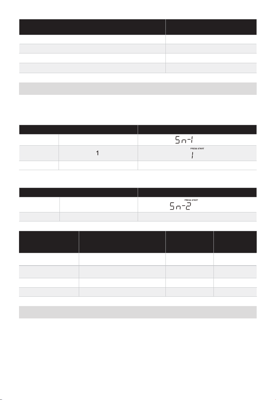
FR-58
APPUYEZ SUR LE PAVÉ DE POMMES DE TERRE OU
SUR LES TOUCHES NUMÉRIQUES
MONTANT
x 1 1
x 2 2
x 3
3
x 4
4
Menus collation
Il existent 4 options (hot-dogs, repas surgeé pour enfants, repas dans une tasse, soupe)
sous le menu des collations.
1. Hot-dogs ou soupe
TOUCHEZ L'ÉCRAN MONTRE :
1.
MENU DES COLLATIONS X 1
2.
3. DÉMARRER + 30 SEC. Compte à rebours
2. Repas surgelé pour enfants
TOUCHEZ L'ÉCRAN MONTRE :
1. MENU DES COLLATIONS X 2
2. DÉMARRER + 30 SEC. Compte à rebours
APPUYEZ SUR LE
PAVÉ DE MENU
DES COLLATIONS
ALIMENT
TOUCHES
NUMÉRIQUE
MONTANT
x 1 Hot-dogs 1, 2, 3, 4, 5, 6 1 - 6 pièces
x 2 Repas surgelé pour enfants - 8,8 onces
x 3 Repas dans une tasse - 2,39 onces
x 4 Soupe 1, 2, 1 - 2 tasses
Cuisine Automatique
Il existent 5 options (bacon, assiette de dîner, riz, petit-déjeuner surgelé, pizza surgelée)
sous le menu cuisinière automatique.
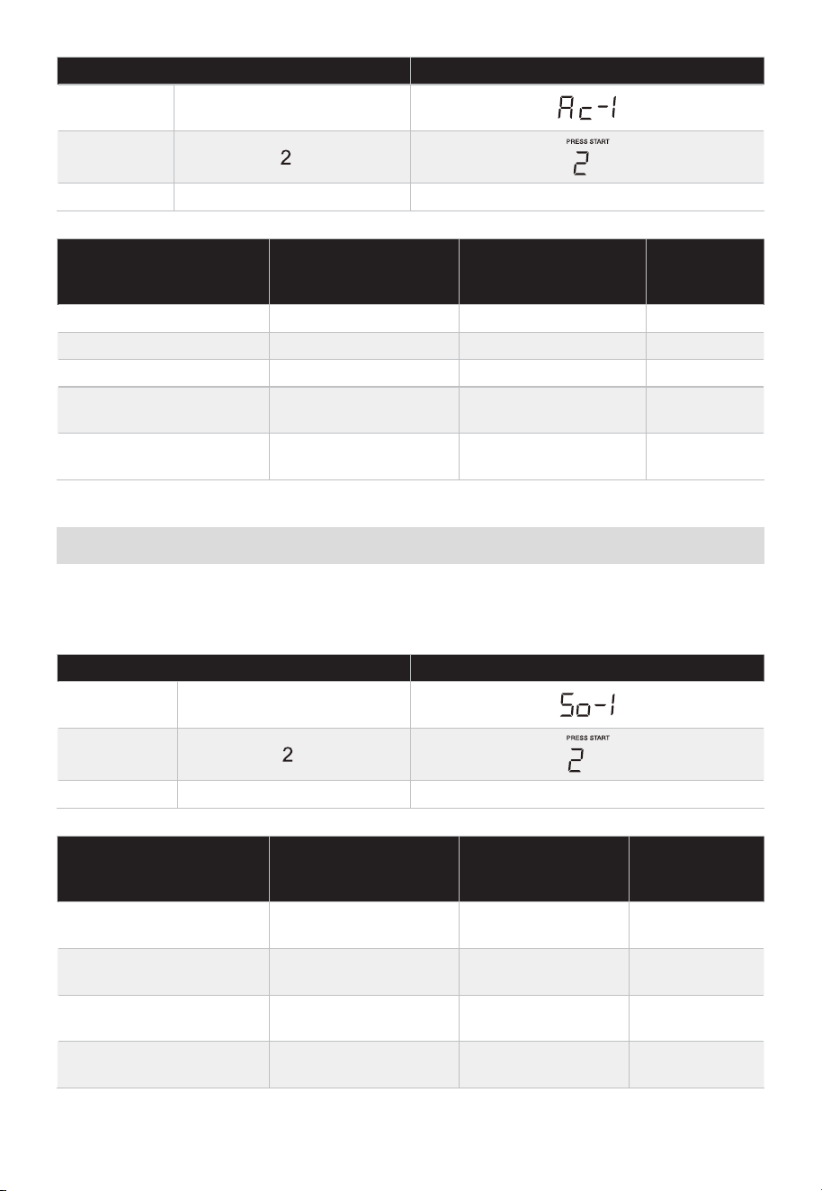
FR-59
TOUCHEZ L'ÉCRAN MONTRE :
1.
2.
3. DÉMARRER + 30 SEC. Compte à rebours
APPUYEZ
SUR MENU
AUTOMATIQUE
ALIMENT
TOUCHES
NUMÉRIQUE
MONTANT
x 1 Bacon 1, 2, 3, 1-3 tranches
x 2 Assiette pour diner 1, 2, 1-2 assiettes
x 3 Riz 1, 2, 1-2 tasses
x 4
Petit-déjeuner
surgelé
1, 2, 8/12 oz
x 5 Pizza congelée 1, 2, 3,
6/8/12
onces
Faire fondre/Ramollir
Le four utilise une faible puissance pour faire fondre et ramollir les articles. Consultez le
tableau suivant.
• Supposons que vous vouliez faire fondre 2 bâtonnets de beurre.
TOUCHEZ L'ÉCRAN MONTRE :
1.
FONDRE/ADOUCIR
X 1
2.
3. DÉMARRER + 30 SEC. Compte à rebours
APPUYEZ SUR LE
PAVÉ FONDRE/
RAMOLLIR
ALIMENT
TOUCHES
NUMÉRIQUE
MONTANT
x 1
Faire fondre du
beurre
1, 2, 1/2 bâton
x 2
Faire fondre le
chocolat
1, 2, 3,
x 3
Ramollir la crème
glacée
1, 2,
Pinte/1,5
Quart
x 4
Ramollir du fromage
à la crème
1, 2, 3/8 oz
MENU AUTOMATIQUE X1
2/4/8 oz
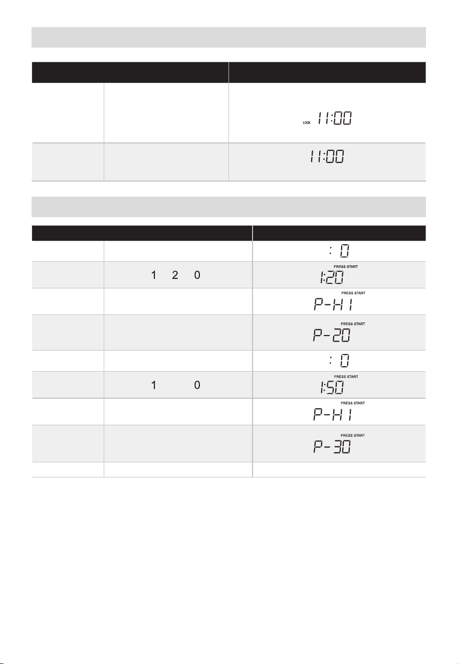
FR-60
Verrouillage enfant
TOUCHEZ L'ÉCRAN MONTRE :
1.
ARRÊTER/EFFACER
(pendant 3 secondes)
VERROUILLAGE
OU
(si l'horloge est réglée)
2.
ARRÊTER/EFFACER
(pendant 3 secondes)
(si l'horloge est réglée)
Cuisson par étape
TOUCHEZ L'ÉCRAN MONTRE :
1. TEMPS DE CUISSON
2.
3. NIVEAU DE PUISSANCE X 1
4.
NIVEAU DE PUISSANCE X 8
5. TEMPS DE CUISSON
6.
5
7. NIVEAU DE PUISSANCE X 1
8.
NIVEAU DE PUISSANCE X 7 ou
3
9. DÉMARRER + 30 SEC. Compte à rebours
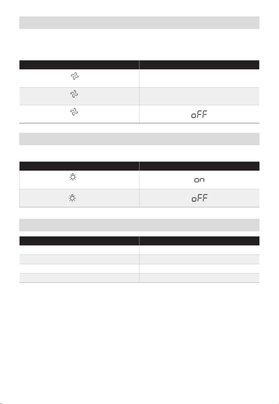
FR-61
Ventilateur
La commande de ventilation contrôle le ventilateur à 2 vitesses. Si le ventilateur de
l'évent est ÉTEINT, la première touche sur le pavé du ventilateur mettra le VENTILATEUR
en position ÉLEVÉE, la deuxième touche en position BASSE et la troisième touche en
position ÉTEINTE.
TOUCHEZ L'ÉCRAN MONTRE :
X 1 HI
X 2 Lo
X 3
Le pavé contrôle la lumière à 2 états. Si la lumière est ÉTEINTE, la première touche du
pavé lumineux allumera la lumière, la deuxième touche S'ÉTEINDRA.
TOUCHEZ L'ÉCRAN MONTRE :
X 1
X 2
Préférences Utilisateur
BOUTON REGLAGE
PRÉF.?? ??UTILISATEUR X 1 Volume Bas/Nor/Éle/Éteint
PRÉF??. UTILISATEUR X 2 Poids (livre/kg)
PRÉF??. UTILISATEUR X 3 Affichage de l'horloge Allumer/Éteindre
PRÉF. UTILISATEUR X 4 Mode Démo
Lampe
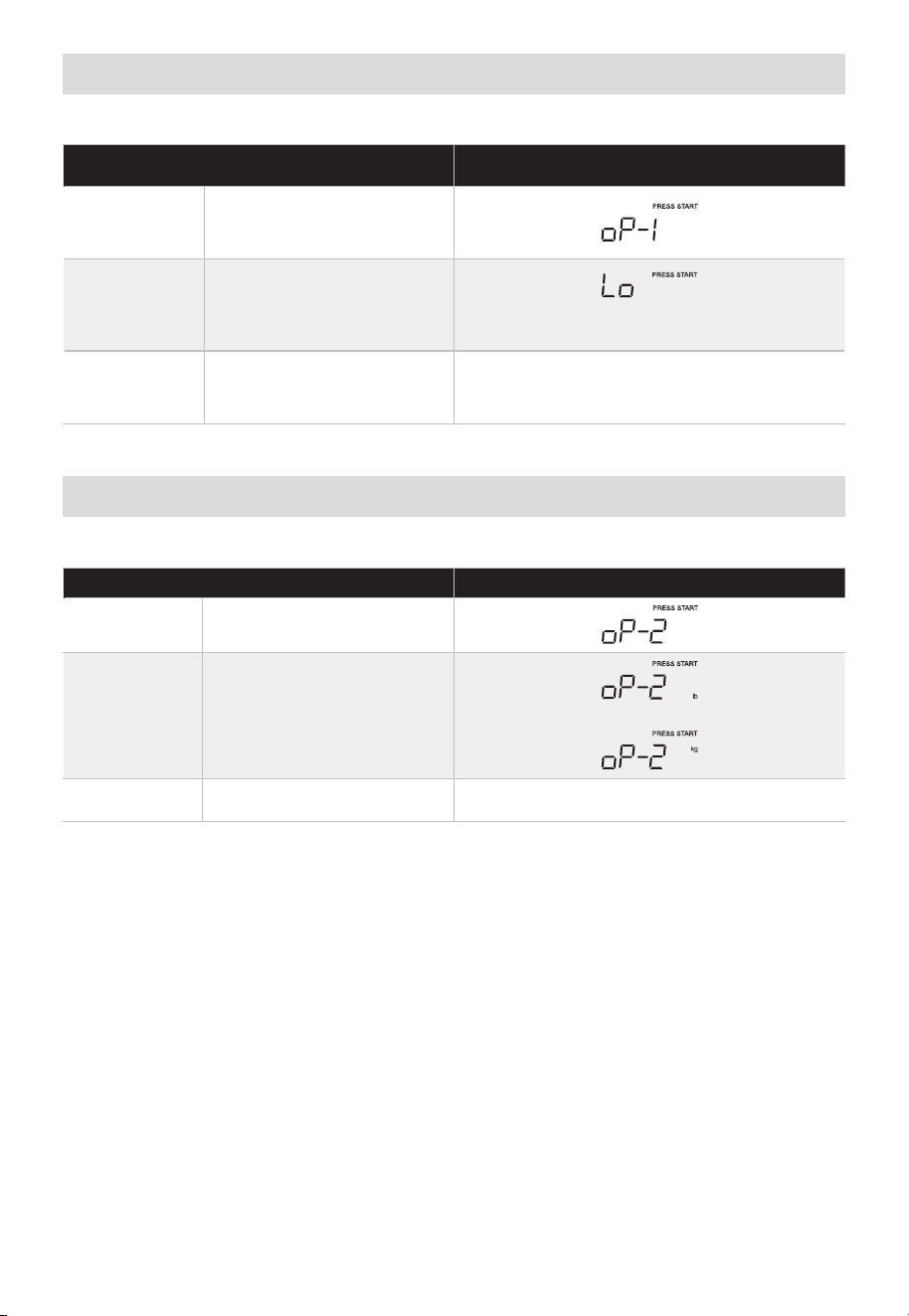
FR-62
Volume
En mode veille :
TOUCHEZ L'ÉCRAN MONTRE :
1.
PRÉF??.
UTILISATEUR X 1
2. DÉMARRER + 30 SEC.
(Bas, NOR, ÉLEV, Éteint s'affichera dans
l'ordre)
3. DÉMARRER + 30 SEC.
Poids (livre/kg)
En mode veille :
TOUCHEZ L'ÉCRAN MONTRE :
1.
PRÉF??.
UTILISATEUR X 2
2. DÉMARRER + 30 SEC.
ou
3. DÉMARRER + 30 SEC.
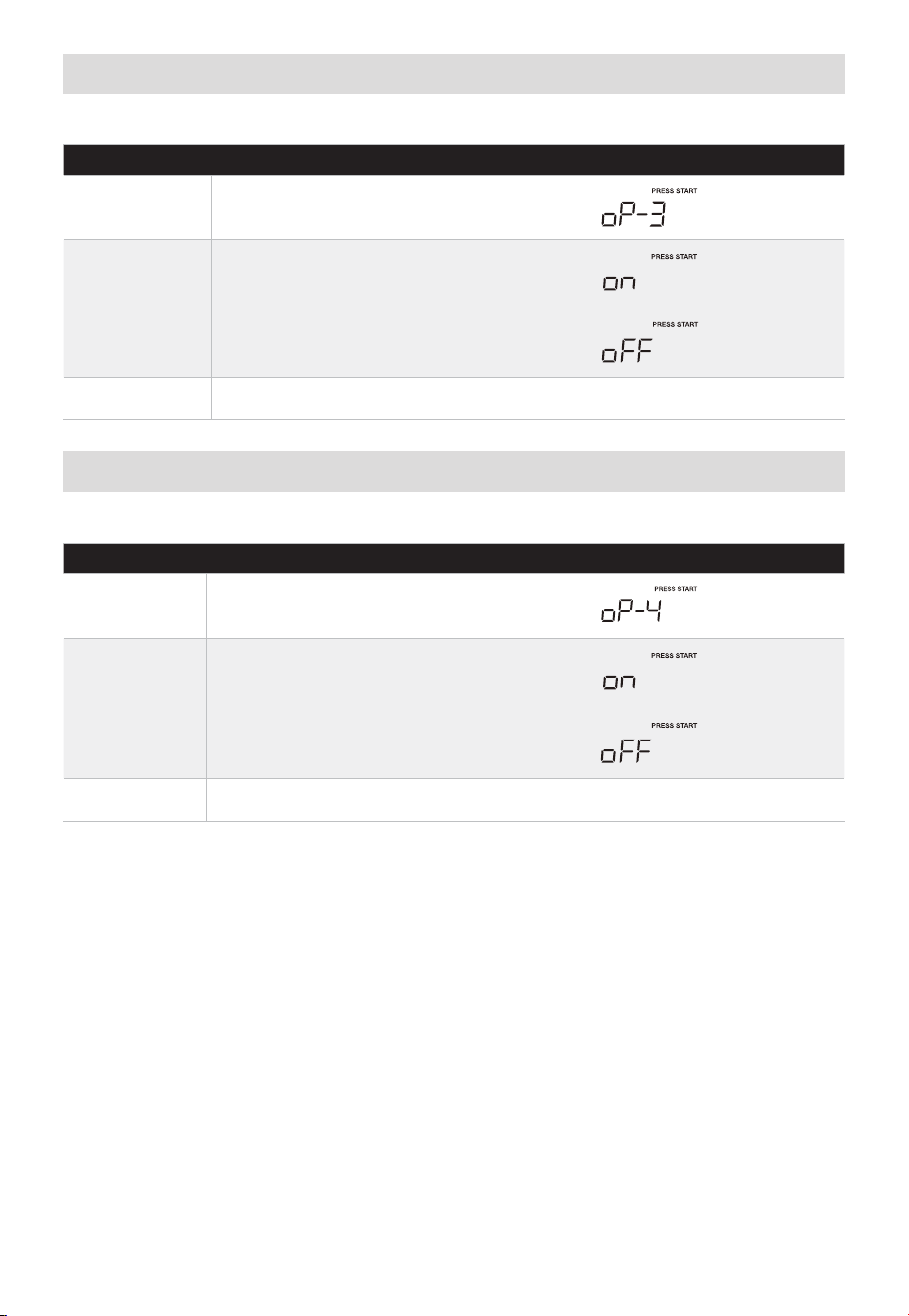
FR-63
Affichage de l'horloge Désactivé/Activé
En mode veille :
TOUCHEZ L'ÉCRAN MONTRE :
1.
PRÉF??.
UTILISATEUR X 3
2. DÉMARRER + 30 SEC.
ou
3. DÉMARRER + 30 SEC.
Mode Démo
En mode veille :
TOUCHEZ L'ÉCRAN MONTRE :
1.
PRÉF??.
UTILISATEUR X 4
2. DÉMARRER + 30 SEC.
ou
3. DÉMARRER + 30 SEC.

FR-64
DÉPANNAGE
Vérifiez votre problème en utilisant le tableau ci-dessous et essayez les solutions pour
chaque problème. Si le four micro-ondes ne fonctionne toujours pas correctement,
contactez le centre de service agréé le plus proche.
PROBLÈME CAUSE POSSIBLE SOLUTIONS POSSIBLES
Le four ne
démarre pas
• Le cordon électrique du four n’est
pas branché.
• La porte est ouverte.
• Une mauvaise opération est
définie.
• Branchez dans la prise.
• Fermez la porte et réessayez.
• Vérifiez les instructions.
Arc ou étincelles
• Les matériels déconseillés dans le
four à micro-ondes ont été utilisés.
• Le four est utilisé lorsqu’il est vide.
• De la nourriture renversée reste
dans le four.
• Utilisez uniquement des ustensiles
de cuisine pour micro-ondes.
• N’utilisez pas le four lorsque celui-
ci est vide.
• Nettoyez l’intérieur avec une
serviette humide.
Aliments cuits de
manière inégale
• Les matériels déconseillés dans le
four à micro-ondes ont été utilisés.
• Les aliments ne sont pas
complètement dégelés.
• La durée de cuisson ou le niveau
de puissance ne convient pas.
• Les aliments ne sont pas tournés
ou mélangés.
• Utilisez uniquement des ustensiles
de cuisine pour micro-ondes.
• Dégelez complètement les
aliments.
• Utilisez une durée de cuisson
et un niveau de puissance
appropriés.
• Tournez ou remuez les aliments.
Aliments trop
cuits
• La durée de cuisson ou le niveau
de puissance ne convient pas.
• Utilisez une durée de cuisson
et un niveau de puissance
appropriés.
Aliments
insuffisamment
cuits
• Les matériels déconseillés dans le
four à micro-ondes ont été utilisés.
• Les aliments ne sont pas
complètement dégelés.
• Les orifices de ventilation du four
sont bloqués.
• La durée de cuisson ou le niveau
de puissance ne convient pas.
• Utilisez uniquement des ustensiles
de cuisine pour micro-ondes.
• Dégelez complètement les
aliments.
• Vérifiez que les orifices de
ventilation du four ne sont pas
obstrués.
• Utilisez une durée de cuisson
et un niveau de puissance
appropriés.
Décongélation
incorrecte
• Les matériels déconseillés dans le
four à micro-ondes ont été utilisés.
• La durée de cuisson ou le niveau
de puissance ne convient pas.
• Les aliments ne sont pas tournés
ou mélangés.
• Utilisez uniquement des ustensiles
de cuisine pour micro-ondes.
• Utilisez une durée de cuisson
et un niveau de puissance
appropriés.
• Tournez ou remuez les aliments.

FR-65
MARQUES, DROITS D'AUTEUR ET
DÉCLARATION LÉGALE
le logo, les marques verbales, le nom commercial, l'habillage commercial et
toutes les versions de ceux-ci sont des actifs précieux du Groupe Midea et/ou de ses
sociétés affiliées («Midea»), auxquels Midea possède des marques, des droits d'auteur
et d'autres droits de propriété intellectuelle, et toute la bonne volonté dérivée de
l'utilisation d'une partie d'une marque Midea. L'utilisation de la marque Midea à des
fins commerciales sans le consentement écrit préalable de Midea peut constituer une
contrefaçon de marque ou une concurrence déloyale en violation des lois pertinentes.
Ce manuel est créé par Midea et Midea se réserve tous les droits d'auteur de celui-ci.
Aucune entité ou individu ne peut utiliser, dupliquer, modifier, distribuer en tout ou en
partie ce manuel, ou regrouper ou vendre avec d'autres produits sans le consentement
écrit préalable de Midea.
Toutes les fonctions et consignes décrites étaient à jour au moment de l'impression de ce
manuel. Cependant, le produit réel peut varier en raison de l'amélioration des fonctions
et des conceptions.

FR-66
AVIS DE PROTECTION DES
DONNÉES
Pour la fourniture des services convenus avec le client,
Nous nous engageons à respecter sans restriction toutes les dispositions de la loi
applicable en matière de protection des données, conformément aux pays dans desquels
les services au client seront fournis.
En règle générale, notre traitement des données vise à remplir notre obligation
contractuelle avec vous et, pour des raisons de sécurité des produits, à protéger vos
droits en ce qui concerne les questions de garantie et d'enregistrement des produits.
Dans certains cas, mais uniquement si une protection appropriée des données est
assurée, les données personnelles peuvent être transférées à des destinataires situés en
dehors de l'Espace économique européen.
De plus amples informations sont fournies sur demande. Vous pouvez contacter
notre responsable de la protection des données par l'adresse électronique
[email protected]. Pour exercer vos droits tels que le droit de vous opposer
au traitement de votre date personnelle à des fins de marketing direct, veuillez nous
contacter par l'adresse électronique [email protected]. Pour plus d'informations,
veuillez scanner le code QR.

FR-67
GARANTIE LIMITÉE D'UN AN
Cette garantie est fournie à la livraison au détail (l '« Acheteur » ou « vous »)
par Midea America Corp. (« Midea » ou « nous »), qui garantit toutes les parties de ce
produit, comme décrit ci-dessous. Midea garantit ce Produit à l'acheteur pour un usage
personnel, familial ou domestique. Cette garantie couvre les problèmes de rendement, de
qualité des matériaux et de la qualité d'exécution qui apparaissent dans le cadre de l'utilisation
normale et d'entretien dans un délai d'un an à compter de la date d'achat. Cette garantie
vous confère des droits spécifiques, et vous permet d’avoir d’autres droits qui varient d’un
État à l’autre. La date de livraison établit la période de garantie, si un entretien est nécessaire.
LIMITATIONS DE GARANTIE
Cette garantie est donnée uniquement à la livraison au détail aux États-Unis ou au
Canada et ne peut être transférée à un acheteur ultérieur. Cette garantie ne s'applique
pas aux acheteurs de nos produits destinés à être utilisés ou revendus dans une
entreprise ; une garantie commerciale distincte peut protéger ces acheteurs.
Cette garantie ne couvre pas les défaillances du produit causées par :
a. Abus, dommage ou utilisation du Produit en violation des consignes du Produit.
b. Modification de tout Produit ou pièce.
c. Défaut d'entretien du produit ou de la pièce tel que décrit conformément aux
instructions du produit.
d. Installation ou application défectueuse.
e. Utilisation de pièces ou d'accessoires non compatibles avec ce produit.
f. Inondations, incendies, vents, foudre, accidents, atmosphère corrosive ou autres
conditions indépendantes de la volonté de Midea.
g. Interruption du service électrique ou service électrique inadéquat.
h. Remplacement des fusibles et remplacement ou réarmement des disjoncteurs.
i. Tuyaux d'eau gelés ou cassés, dégâts d'eau, intrusion d'humidité, moisissure ou autre
croissance biologique.
j. L'utilisation, la combinaison ou la liaison du Produit à d'autres produits, processus ou
matériaux non fournis par Midea.
RECOURS SOUS GARANTIE
Si un problème de qualité ou de performance couvert par cette garantie est découvert
pendant la période de garantie, nous réparerons ou remplacerons, à notre choix, un tel
produit. Cette garantie est limitée à la réparation ou au remplacement du produit par un
réparateur ou un concessionnaire Midea agréé et ne couvre pas les frais d'expédition, les
coûts de main-d'œuvre, les droits de douane, les coûts de logistique interne ou les coûts
de service, y compris les coûts de diagnostic, de retrait, de transport ou de réinstallation.
Si nous vous le demandons, vous devez nous retourner le produit.
CLAUSE DE NON-RESPONSABILITÉ DE GARANTIE ; EXCLUSION DE DOMMAGES
Il s'agit de la seule garantie expresse que nous offrons aux consommateurs sur nos
produits. TOUTE GARANTIE IMPLICITE DE MIDEA, Y COMPRIS, MAIS SANS S'Y
LIMITER, LES GARANTIES DE QUALITÉ MARCHANDE ET D'ADÉQUATION À UN
USAGE PARTICULIER, EST LIMITÉE À LA DURÉE DE CETTE GARANTIE EXPRESSE.
Certains États et provinces n'autorisent pas l'exclusion des garanties expresses et/ou
des limitations sur la durée d'une garantie implicite, de sorte que l'exclusion et/ou la
limitation ci-dessus peuvent ne pas s'appliquer à vous.
LE RECOURS DÉCRIT CI-DESSUS EST LE SEUL QUE NOUS FOURNIRONS, SOIT EN
VERTU DE CETTE GARANTIE, SOIT EN VERTU DE TOUTE GARANTIE DÉCOULANT DE
L'EXPLOITATION DE LA LOI. NOUS NE SERONS PAS RESPONSABLES DES DOMMAGES

FR-68
CONSÉCUTIFS OU ACCESSOIRES DÉCOULANT DE LA VIOLATION DE CETTE GARANTIE
OU DE TOUTE AUTRE GARANTIE, EXPRESSE OU IMPLICITE, DE LA NÉGLIGENCE OU DE
TOUT AUTRE DÉLIT, OU DE TOUTE THÉORIE DE RESPONSABILITÉ STRICTE, Y COMPRIS,
MAIS SANS S'Y LIMITER, LA PERTE DE PROFITS.
Certains États et provinces n’autorisent pas l’exclusion ou la limitation des dommages directs
ou indirects, de sorte que ces limitations et exclusions peuvent ne pas s’appliquer à vous.
PROCESSUS DE RÉCLAMATION DE GARANTIE
Pour plus d'informations ou pour faire une demande de garantie, veuillez visiter :
https://www.midea.com/Canada/support
Ou contactez-nous au :
Téléphone : 1-888-365-2230
E-mail : [email protected]
Vous devez avoir votre facture de vente, votre bon de livraison ou une preuve d'achat
appropriée pour soumettre une réclamation au titre de la garantie. La date d’achat
établit la période de garantie, si un service venait à s'avérer nécessaire.
RÉSOLUTION DES LITIGES
CLAUSE D'ARBITRAGE. IMPORTANT. VEUILLEZ PRENDRE CONNAISSANCE CETTE
CLAUSE COMPROMISSOIRE. ELLE AFFECTE VOS DROITS LÉGAUX.
a. Parties : Cette clause d'arbitrage (« Clause d'arbitrage ») affecte vos droits à
l’encontre de Midea et toutes ses sociétés affiliées, ses employés ou agents,
successeurs ou ayants droit, qui sont tous ci-après désignés par « nous » ou « notre »
pour des raisons de commodité.
b. EXIGENCE D'ARBITRAGE : À L'EXCEPTION DE CE QUI EST INDIQUÉ CI-DESSOUS,
TOUT LITIGE ENTRE VOUS ET L'UN DE NOUS SERA TRANCHÉ PAR ARBITRAGE
NEUTRE ET CONTRAIGNANT PLUTÔT QUE PAR UN TRIBUNAL OU PAR UN
PROCÈS DEVANT JURY. Le terme « Litige » prend son sens le plus large possible
autorisé par la loi. Cela inclut tout litige, réclamation ou controverse découlant de
ou lié à votre achat de ce produit, toute garantie sur le produit ou l'état du produit.
Il comprend également la détermination de la portée ou de l'applicabilité de la
présente clause compromissoire. L'exigence d'arbitrage s'applique aux réclamations
contractuelles et délictuelles, en vertu de la loi ou autrement.
c. RENONCIATION À L'ARBITRATION DE CLASSE : L'ARBITRAGE EST TRAITÉ
SUR UNE BASE INDIVIDUELLE. SI UN LITIGE EST ARBITRÉ, VOUS ET NOUS
RENONÇONS EXPRESSÉMENT À TOUT DROIT DE PARTICIPER EN TANT QUE
REPRÉSENTANT DU GROUPE OU MEMBRE DU GROUPE À TOUTE RÉCLAMATION
DU GROUPE QUE VOUS POURRIEZ AVOIR CONTRE NOUS OU NOUS CONTRE
VOUS, OU EN TANT QUE PROCUREUR GÉNÉRAL PRIVÉ OU EN TOUTE AUTRE
QUALITÉ REPRÉSENTATIVE, DANS TOUTE LA MESURE PERMISE PAR LA LOI.
VOUS ET NOUS RENONÇONS ÉGALEMENT À TOUT DROIT À L'ARBITRAGE DE
CLASSE OU À TOUTE CONSOLIDATION D'ARBITRAGES INDIVIDUELS.
d. Découverte et autres droits : La découverte et les droits d'appel en arbitrage sont
généralement plus limités que dans un procès. Cela s'applique à vous et à nous. Les autres
droits que vous ou nous aurions devant un tribunal peuvent ne pas être disponibles dans
le cadre d'un arbitrage. Veuillez lire cette clause d'arbitrage et consulter le règlement des
organisations d'arbitrage énumérées ci-dessous pour plus d'informations.
e. OPTION DE TRIBUNAL DES PETITES CRÉANCES : VOUS POUVEZ CHOISIR DE
PLAIDER TOUT LITIGE ENTRE VOUS ET L'UN DE NOUS DEVANT LA COUR DES
PETITES CRÉANCES, PLUTÔT QU'EN ARBITRAGE, SI LE LITIGE RÉPOND À TOUTES
LES EXIGENCES POUR ÊTRE ENTENDU DEVANT LA COUR DES PETITES CRÉANCES.
f. Loi applicable : Pour les résidents des États-Unis, les procédures et les effets de
l'arbitrage seront régis par la loi fédérale sur l'arbitrage (9 U.S.C. § 1 et suivants)
plutôt que par la loi de l'État concernant l'arbitrage. Pour les résidents du Canada, les

FR-69
procédures et les effets de l'arbitrage seront régis par la loi d'arbitrage applicable de
la province dans laquelle vous avez acheté votre Produit. La loi régissant vos droits
de garantie substantiels et autres réclamations sera la loi de l'État ou de la province
dans lequel vous avez acheté votre Produit. Tout tribunal compétent peut rendre un
jugement sur la sentence arbitrale.
g. Règlement de l'arbitrage : Si le montant en litige est inférieur à 250 000 $ , l'arbitrage
sera décidé par un seul arbitre. Si le montant en litige est supérieur ou égal à 250
000 $ , l'arbitrage sera décidé par un panel de trois arbitres. Le ou les arbitre(s)
seront choisis conformément aux règles de l'organisation d'arbitrage administrante.
Les résidents des États-Unis peuvent choisir JAMS (1920 Main Street, Ste. 300,
Irvine, CA 92614, www.jamsadr.com), ou, sous réserve de notre approbation, toute
autre organisation d'arbitrage. De plus, les résidents canadiens peuvent choisir
l'Institut ADR du Canada (234 Eglinton Ave. East, Suite 405, Toronto, Ontario, M4P
1K5, www.amic.org). Les règles de ces organisations peuvent être obtenues en
contactant l'organisation ou en visitant son site Web. Si les règles de l'organisation
d'arbitrage choisie sont en conflit avec la présente clause d'arbitrage, les dispositions
de la présente clause d'arbitrage prévalent. La sentence du ou des arbitre(s) sera
définitive et contraignante pour toutes les parties.
h. Lieu de l'audience d'arbitrage : À moins que la loi applicable n'en dispose autrement,
l'audience d'arbitrage pour les résidents des États-Unis se déroulera dans le district
judiciaire fédéral dans lequel vous résidez (dans votre région natale) ou, pour
les résidents canadiens, dans la province dans laquelle vous résidez et, si vous le
souhaitez, en personne.
i. Frais de l'arbitrage : Chaque partie est responsable de ses propres frais d'avocat,
d'expert et autres, à moins que la loi applicable n'exige le contraire. Nonobstant la
phrase précédente, et sauf disposition contraire de la loi applicable, si vous êtes un
consommateur en vertu des règles JAMS ou des règles d'un autre administrateur
d'arbitrage convenu, Midea vous paiera ou vous remboursera tous les frais ou coûts
raisonnables dans la mesure requise par la loi ou les règles de l'administrateur
d'arbitrage applicable. Que la loi ou de telles règles l'exigent ou non, si vous
l'emportez à l'arbitrage sur toute réclamation contre Midea, Midea vous remboursera
tous les frais raisonnables payés à l'administrateur d'arbitrage dans le cadre de la
procédure d'arbitrage. En aucun cas, Midea ne vous demandera le paiement ou le
remboursement des frais raisonnables que Midea encourt dans le cadre de l'arbitrage.
Si vous devez avancer des frais ou des coûts à JAMS ou à un autre administrateur
d'arbitrage convenu, mais que vous demandez à Midea de le faire à votre place,
Midea examinera et répondra à votre demande.
j. Survie et force exécutoire de la présente clause compromissoire : La présente clause
d'arbitrage survivra à l'expiration ou à la résiliation, ou à tout transfert, de la garantie
sur votre produit. Si une partie de la présente clause d'arbitrage, à l'exception des
renonciations aux droits d'action collective, est jugée inapplicable pour quelque
raison que ce soit, le reste de la présente clause et la garantie resteront exécutoires.
Si, dans un cas où des allégations de recours collectif ont été faites, la renonciation
aux droits de recours collectif en vertu de la présente garantie est jugée inapplicable
à l'égard d'une partie du litige, les parties du litige à l'égard desquelles la
renonciation aux droits de recours collectif a été jugée inapplicable seront coupées
et procéderont devant un tribunal sans référence ou application de la présente
clause d'arbitrage. Toutes les parties restantes feront l'objet d'un arbitrage.
RÉSIDENTS QUÉBÉCOIS
Les dispositions d'arbitrage de cette garantie ne s'appliquent pas aux résidents du Québec.


www.midea.com
© Midea 2024 tous droits réservés