ICC-ES Evaluation Reports are not to be construed as representing aesthetics or any other attributes not specifically addressed, nor are they to be construed
as an endorsement of the subject of the report or a recommendation for its use. There is no warranty by ICC Evaluation Service, LLC, express or implied, as
to any finding or other matter in this report, or as to any product covered by the report.
Cop
yright © 2022 ICC Evaluation Service, LLC. All rights reserved. Page 1 of 10
www.icc-es.org | (800) 423-6587 | (562) 699-0543 A Subsidiary of the International Code Council
®
ICC-ES Evaluation Report Issued March 2022
ESR-4
893
This report is subject to renewal March 2023.
DIVISION: 03 00 00—CONCRETE
Section: 03 15 00—Concrete Accessories
Section: 03 16 00—Concrete Anchors
DIVISION: 04 00 00—MASONRY
Section: 04 05 19.16—Masonry Anchors
DIVISION: 05 00 00—METALS
Section: 05 05 23—Metal Fastenings
DIVISION: 09 00 00—FINISHES
Section: 09 22 16.23—Fasteners
REPORT HOLDER:
ROBERT BOSCH TOOL CORPORATION
EVALUATION SUBJECT:
BOSCH FASTENERS
1.0 EVALUATION SCOPE
Compliance with the following codes:
2021, 2018, 2015 and 2012 International Building Code
®
(IBC)
2021, 2018, 2015 and 2012 International Residential
Code
®
(IRC)
For evaluation for compliance with codes adopted by the
Los Angeles Department of Building and Safety (LADBS),
see ESR-4893 LABC and LARC Supplement.
Property evaluated:
Structural
2.0 USES
Bosch fasteners are used to attach miscellaneous building
components to base materials of normalweight concrete,
steel deck panels with sand-lightweight concrete fill,
concrete masonry or structural steel. The fasteners are
alternatives to the cast-in-place anchors described in IBC
Section 1901.3 (2012 IBC Section 1908) for placement in
concrete; the embedded anchors described in Section 8.1.3
of TMS 402, referenced in Section 2107 of the IBC (Section
2.1.4 of TMS 402-11, referenced in Section 2107 of the
2012 IBC) for placement in masonry; and the welds and
bolts used to attach materials to steel, described in IBC
Sections 2204.1 and 2204.2, respectively. For structures
regulated under the IRC, the fasteners may be used where
an engineered design is submitted in accordance with IRC
Section R301.1.3.
3.0 DESCRIPTION
3.1 Fasteners:
Bosch fasteners are power-actuated fasteners (PAFs)
manufactured from carbon steel which is hardened in
accordance with the manufacturer’s quality documentation.
The minimum specified core hardness for the fastener is
53 HRC. The fasteners have zinc plating. See Table 1 for
shank type and fastener dimensions. Maximum point length
is the maximum specified length from the tip of the fastener
to the location where the diameter of the shank becomes
constant. Minimum effective shank length is the minimum
specified length from the underside of the fastener head to
the tip of the fastener.
3.2 Substrate Materials:
3.2.1 Concrete: Uncracked normalweight and sand-
lightweight concrete must comply with IBC Chapter 19 or
IRC Section R402.2, as applicable. The minimum concrete
compressive strength at the time of fastener installation
must be as noted in the applicable allowable load table.
3.2.2 Concrete Masonry: Concrete masonry units
(CMUs) must be uncracked lightweight units complying with
ASTM C90, having a face shell thickness of 1.25 inches
(32 mm).
3.2.3 Steel: Structural steel supports must comply with the
minimum requirements of ASTM A36 or ASTM A572 Grade
50, as applicable, and must have minimum thickness as
noted in Tables 2A and 2B, as applicable.
3.2.4 Steel Deck Panels: Steel deck panel properties and
configurations must be as described in footnote 4 of Tables
4A and 4B and Figures 5 and 6.
4.0 DESIGN AND INSTALLATION
4.1 Design:
4.1.1 General: Selection of fasteners must take into
consideration the applicable base material and the length of
the fastener. The minimum fastener length must be
determined as follows:

ESR-4893
|
Most Widely Accepted and Trusted Page 2 of 10
• For installation into concrete, concrete-filled steel deck
panels, concrete masonry and steel base materials,
the minimum effective shank length shown in Table 1
must equal or exceed the sum of the thickness of the
attached material and the minimum embedment depth
(penetration) shown in the applicable tables in this
report.
• For installation through steel base materials, the
minimum effective shank length shown in Table 1 must
equal or exceed the sum of the following: the thickness
of the attached material, the thickness of the base
material and the required point penetration beyond the
base material as shown in the applicable tables in this
report.
4.1.2 Allowable Loads: The applicable allowable load
tables for Bosch power-actuated fasteners driven into
different base materials are shown in Table 1.
The most critical applied loads, excluding seismic load
effects, resulting from the load combinations in Section 2.4
of ASCE 7-16/S1 (referenced in 2021 IBC Section 1605.1)
or 2021 IBC Section 1605.2 (Section 1605.3.1 or 1605.3.2
of the 2018, 2015 and 2012 IBC) must not exceed the
allowable loads in Tables 2 through 5 of this report. For
fasteners which are subjected to seismic loads, see Section
4.1.5 for additional information. The stress increases and
load reductions described in 2021 IBC Section 1605.2
(2018, 2015 and 2012 IBC Section 1605.3) are not allowed.
Allowable shear loads and tension loads in this report
apply to the connection of the fastener to the base material
only. Other limit states applicable to the design of a
connection, such as fastener pull-through (pull-over) and
lateral bearing on the attached material, which are governed
by the properties of attached materials, are outside the
scope of this report. Design of the connection to the
attached material must comply with the applicable
requirements of the IBC.
4.1.3 Combined Loading: For fasteners subjected to both
tension and shear loads, compliance with the following
interaction equation must be verified:
(p/P
a
) + (v/V
a
) ≤ 1
where:
p = Actual applied tension load on fastener, lbf (N).
P
a
= Allowable tension load on fastener, lbf (N).
v = Actual applied shear load on fastener, lbf (N).
V
a
= Allowable shear load on fastener, lbf (N).
4.1.4 Steel-to-steel Connections: When the Bosch
fasteners listed in Tables 2A and 2B are used in connections
of two steel elements in direct contact with one another and
in accordance with Section J5 of AISI S100 (Section E5 of
AISI S100-12 for the 2015 and 2012 IBC), connection
capacity must be determined in accordance with Sections
4.1.4.1 and 4.1.4.2, as applicable.
4.1.4.1 Connection Strength—Tension: To determine
tensile connection strength in accordance with Section J5.2
of AISI S100 (Section E5.2 of AISI S100-12), fastener
tension strength, the pull-out strength and the pull-over
strength must be known. These characteristics must be
determined as follows:
• Pull-out Strength: See Table 2A or 2B for available
pull-out strength, as applicable.
• Pull-over Strength: The available pull-over strengths
must be calculated in accordance with Section J5.2.3
of AISI S100 (Section E5.2.3 of AISI S100-12).
• PAF Tensile Strength: The allowable fastener tension
strengths must be determined in accordance with
Section J5.2.1 of AISI S100 (Section E5.2.1 of AISI
S100-12).
4.1.4.2 Connection Strength—Shear: To determine
shear connection strength in accordance with Section J5.3
of AISI S100 (Section E5.3 of AISI S100-12), the fastener
shear strength, bearing and tilting strength, pull-out strength
in shear, net section rupture strength and shear strength
limited by edge distance must be known. These
characteristics must be determined as follows:
• Bearing and Tilting Strength: The available bearing
and tilting strengths must be calculated in accordance
with Section J5.3.2 of AISI S100 (Section E5.3.2 of
AISI S100-12).
• Pull-out Strength in Shear: The available pull-out
strength in shear must be the applicable allowable
shear strength from Table 2A or 2B or must be
calculated in accordance with Section J5.3.3 of AISI
S100 (Section E5.3.3 of AISI S100-12).
• Net Section Rupture Strength and Shear Strength
Limited by Edge Distance: The net section rupture
strength must be determined in accordance with
Section J5.3.4 of AISI S100 (Section E5.3.4 of AISI
S100-12) and the shear strength limited by edge
distance must be determined in accordance with
Section J5.3.5 of AISI S100 (Section E5.3.5 of AISI
S100-12).
• PAF Shear Strength: The allowable fastener shear
strengths must be determined in accordance with
Section J5.3.1 of AISI S100 (Section E5.3.1 of AISI
S100-12).
4.1.5 Seismic Considerations: When subjected to
seismic loads, the Bosch fasteners may be used as follows:
1. The Bosch fasteners may be used for attachment of
nonstructural components listed in Section 13.1.4 of
ASCE/SEI 7, which are exempt from the requirements
of ASCE/SEI 7.
2. Concrete base materials: The Bosch fasteners
installed in concrete may be used to support distributed
systems and distribution systems where the service
load on any individual fastener does not exceed the
lesser of 90 lbf (400 N) or the allowable load shown in
Tables 3, 4A and 4B, as applicable.
3. Steel base materials: The Bosch fasteners may be
used for attaching nonstructural components where
the service load on any individual fastener does not
exceed the lesser of 250 lbf (1112 N) or the published
allowable load shown in Table 2A or 2B, as applicable.
4. For interior, nonstructural walls that are not subject to
sustained tension loads and are not a bracing
application, the power-actuated fasteners may be used
to attach steel track to concrete or steel in all Seismic
Design Categories. In Seismic Design Categories D, E
and F, the allowable shear load due to transverse
pressure must be no more than the allowable load
described in Item 2 when attaching to concrete; or the
allowable load described in Item 3, above, when
attaching to steel. Substantiating calculations must be
submitted addressing the fastener-to-base-material
capacity and the fastener-to-attached-material
capacity. Interior nonstructural walls are limited to
locations where bearing walls, shear walls or braced
walls are not required by the approved plans. The
design load on the fastener must not exceed the
allowable load established in this report for the
concrete or steel base material.
ESR-4893
|
Most Widely Accepted and Trusted Page 3 of 10
4.2 Installation:
The fasteners must be installed in accordance with this
report and the Bosch published installation instructions. A
copy of these instructions must be available on the jobsite
at all times during fastener installation. In the event of
conflict between this report and the Bosch published
instructions, the more restrictive requirements govern.
Fastener installation requires the use of a gas-actuated
tool in accordance with Bosch recommendations.
The fastener size, minimum embedment depth or
penetration, minimum spacing, and edge distances must
comply with Tables 2 through 5, as applicable. For fasteners
installed into concrete, the fasteners must not be driven until
the concrete has reached the designated compressive
strength.
5.0 CONDITIONS OF USE
The Bosch fasteners described in this report comply with, or
are suitable alternatives to what is specified in, those codes
listed in Section 1.0 of this report, subject to the following
conditions:
5.1 Fasteners must be manufactured and identified in
accordance with this report.
5.2 Calculations demonstrating that the applied loads are
less than the allowable loads described in this report
must be submitted to the code official for approval. The
calculations must be prepared by a registered design
professional where required by the statutes of the
jurisdiction in which the project is constructed.
5.3 For steel-to-steel connections that meet the
applicability requirements of Section J5 of AISI S100-
16 (Section E5 of AISI S100-12 for the 2015 and 2012
IBC), calculations demonstrating that the available
connection strength has been determined in
accordance with Section J5 of AISI S100-16 (Section
E5 of AISI S100-12) and Section 4.1.4 of this report,
and equals or exceeds the applied load, must be
submitted to the code official. The calculations must be
prepared by a registered design professional where
required by the statutes of the jurisdiction in which the
project is to be constructed.
5.4 Refer to Section 4.1.5 for seismic considerations.
5.5 The fasteners must be limited to dry, interior locations,
which include exterior walls which are protected by an
exterior wall envelope.
5.6 The use of fasteners in concrete or masonry is limited
to installation in uncracked concrete or masonry.
Cracking occurs when f
t
> f
r
due to service loads or
deformations.
5.7 The Bosch products addressed in this report are
manufactured under a quality-control program with
inspections by ICC-ES.
6.0 EVIDENCE SUBMITTED
Data in accordance with the ICC-ES Acceptance Criteria for
Power-actuated Fasteners Driven into Concrete, Steel, and
Masonry Elements (AC70), dated December 2019
(editorially revised January 2021).
7.0 IDENTIFICATION
7.1 The heads of the Bosch fasteners are marked as
shown in Figure 4. Packages of fasteners are identified
with the report holder name (Bosch), the fastener type
and size and the evaluation report number (ICC-ES
ESR-4893).
7.2 The report holder’s contact information is the following:
ROBERT BOSCH TOOL CORPORATION
1800 W. CENTRAL ROAD
MOUNT PROSPECT, ILLINOIS 60056
(224) 232-2000
www.boschtools.com
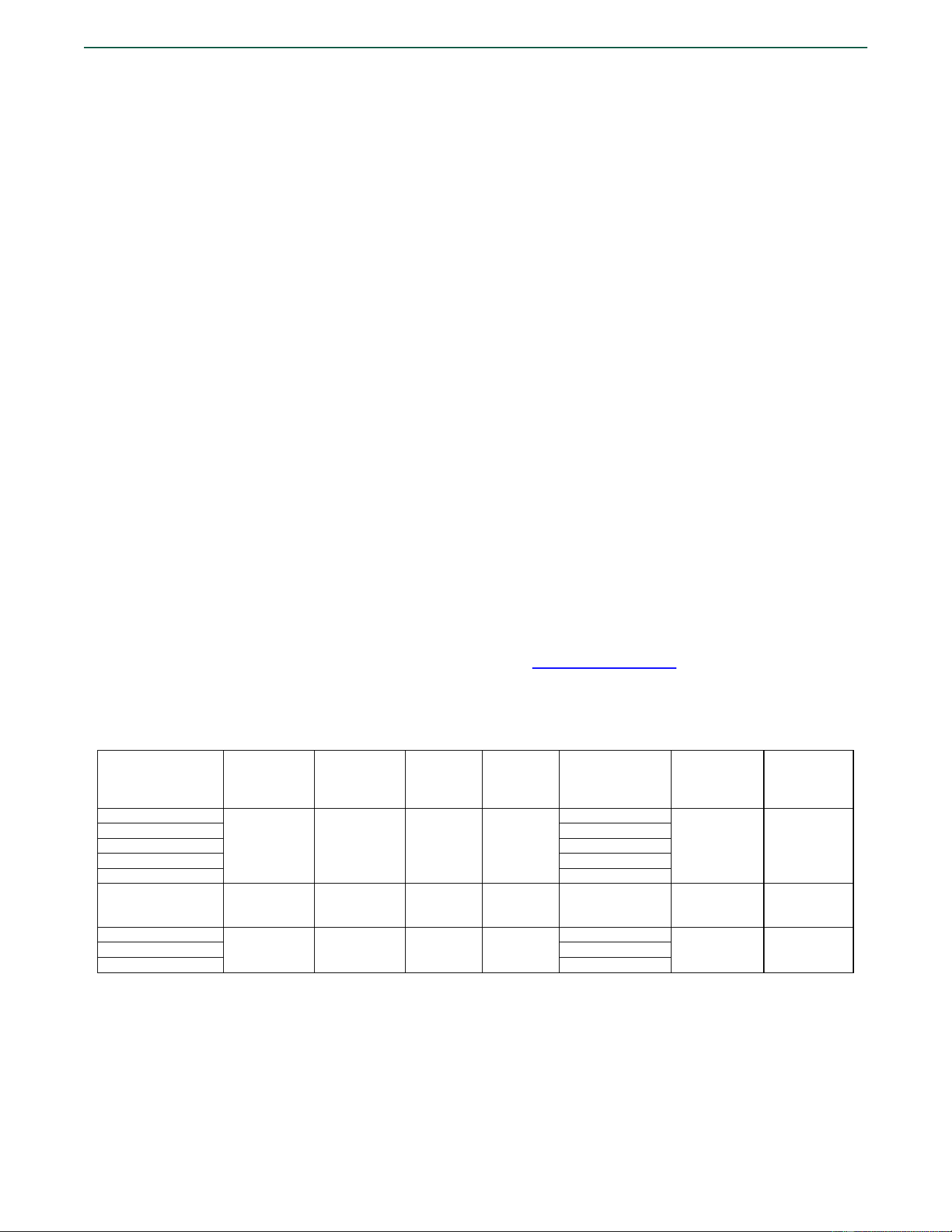
TABLE 1—FASTENER DESCRIPTION AND APPLICATIONS
FASTENER
DESIGNATIONS
1
SHANK TYPE
SHANK
DIAMETER
[inch (mm)]
HEAD
DIAMETER
,
[inch (mm)]
MAXIMUM
POINT
LENGTH
[inch (mm)]
MINIMUM
EFFECTIVE
SHANK LENGTH
[inches (mm)]
APPLICABLE
BASE
MATERIAL
APPLICABLE
LOAD
TABLES
NB-063, NB-16
Straight,
smooth
0.106 (2.7)
0.246 (6.25)
0.217 (5.5)
0.543 (13.8)
Steel, concrete,
concrete-filled
deck, CMU
2A, 2B, 3, 4A,
4B, 5
NB-075, NB-19
0.661 (16.8)
NB-100, NB-25
0.898 (22.8)
NB-125, NB-32
1.17 (29.8)
NB-150, NB-38
1.41 (35.8)
NK-138, NK-35
Straight,
knurled
0.106 (2.7) 0.246 (6.25)
0.217 (5.5) 1.29 (32.8)
Steel, concrete,
concrete-filled
deck, CMU
2A, 2B, 3, 4A,
4B, 5
NM-050, NM-13
Stepped,
smooth
0.117/0.102
(3.00/2.60)
0.246 (6.25)
0.217 (5.5)
0.421 (10.7)
Steel, concrete,
CMU
2A, 2B, 3, 5
NM-063, NM-16
0.539 (13.7)
NM-075, NM-19
0.657 (16.7)
For SI: 1 inch = 25.4 mm.
1
Numerical digits represent the overall length of the fastener in inches (designations with three numerical digits) or in mm (designations with two
numerical digits).
ESR-4893
|
Most Widely Accepted and Trusted Page 4 of 10
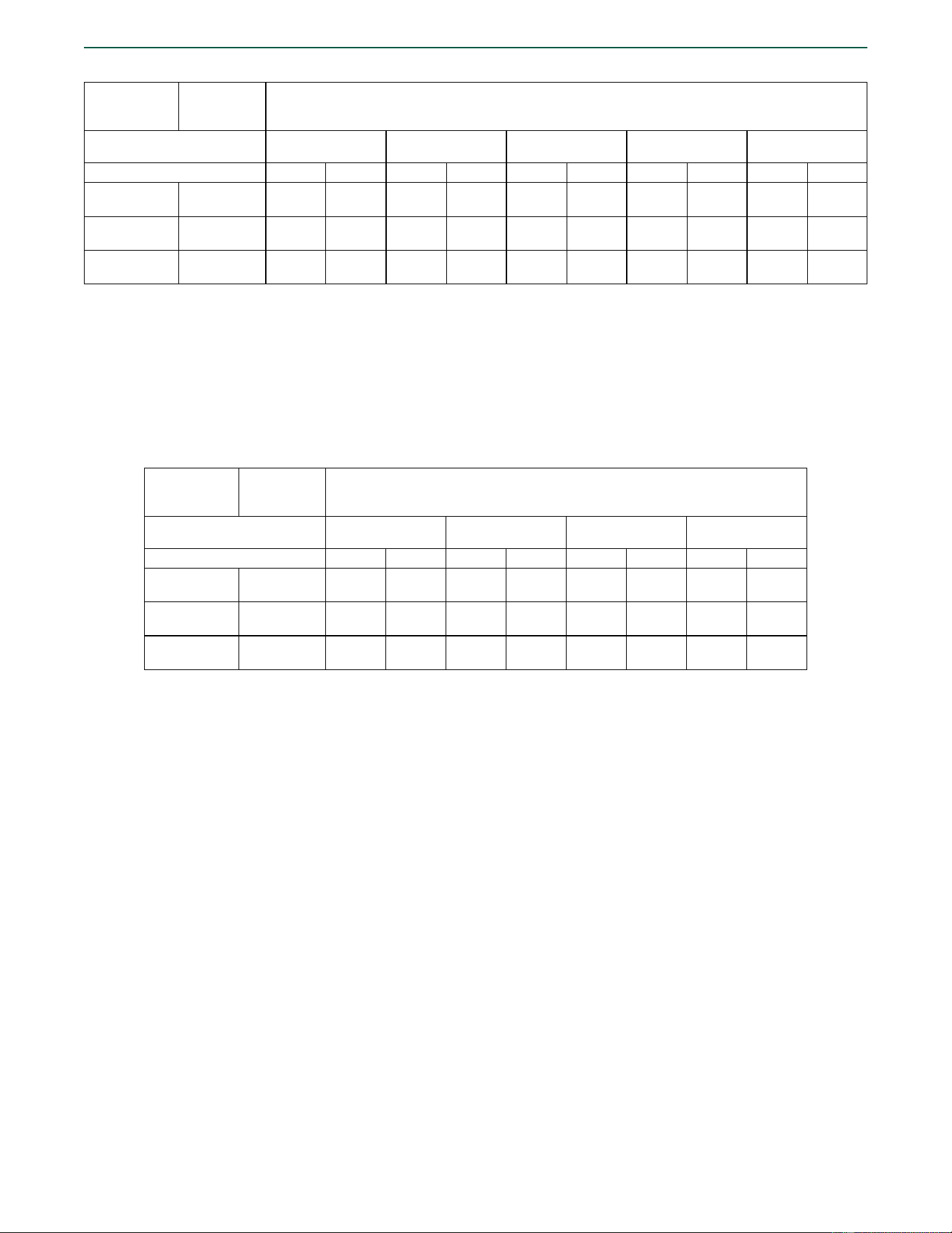
TABLE 2A—ALLOWABLE LOADS FOR FASTENERS DRIVEN INTO ASTM A36 STEEL
1,2,3,4,5,6
FASTENER
DESIGNATION
SHANK
DIAMETER
[inch (mm)]
ALLOWABLE LOADS
[lbf (N)]
Steel Thickness [inch (mm)]:
1
/
8
(3.2)
3
/
16
(4.8)
1
/
4
(6.4)
3
/
8
(9.5)
1
/
2
(12.7)
Load Direction:
Tension
Shear
Tension
Shear
Tension
Shear
Tension
Shear
Tension
Shear
NB 0.106 (2.7)
120
(534)
210
(934)
205
(912)
230
(1,023)
215
(956)
250
(1,112)
260
(1,157)
250
(1,112)
– –
NK 0.106 (2.7)
135
(601)
190
(845)
180
(801)
275
(1,223)
220
(979)
300
(1,335)
230
(1,023)
350
(1,557)
250
(1,112)
–
NM
0.117/0.102
(3.00/2.60)
170
(756)
155
(689)
210
(934)
235
(1,045)
250
(1,112)
285
(1,268)
290
(1,290)
345
(1,535)
– –
For SI: 1 inch = 25.4 mm, 1 ksi = 6.89 MPa, 1 lbf = 4.45 N.
1
Fasteners must be driven to where the full length of the point of the fastener penetrates through the steel base material.
2
The tabulated design values apply only to the fastener in the steel base material. Design of the connection to the attached material is outside the scope of this
report and must comply with the applicable requirements of the IBC.
3
Tabulated loads apply to static load conditions only. For seismic loading, allowable loads must be limited in accordance with Section 4.1.5, Item 3.
4
Steel base material must have minimum yield and tensile strengths (F
y
and F
u
) equal to 36 ksi and 58 ksi, respectively.
5
Fastener spacing must be a minimum of 1.0 inch and edge distance must be a minimum of 0.50 inch.
6
For steel-to-steel connections designed in accordance with Section 4.1.4, the tabulated allowable tension loads may be increased by a factor of 1.25, and the
design strength may be taken as the tabulated allowable load multiplied by a factor of 2.0.
T
ABLE 2B—ALLOWABLE LOADS FOR FASTENERS DRIVEN INTO ASTM A572 GRADE 50 STEEL
1,2,3,4,5,6
FASTENER
DESIGNATION
SHANK
DIAMETER
[inch (mm)]
ALLOWABLE LOADS
[lbf (N)]
Steel Thickness [inch (mm)]:
1
/
8
(3.2)
3
/
16
(4.8)
1
/
4
(6.4)
3
/
8
(9.5)
Load Direction:
Tension
Shear
Tension
Shear
Tension
Shear
Tension
Shear
NB 0.106 (2.7)
140
(623)
225
(1,001)
225
(1,001)
245
(1,090)
260
(1,157)
365
(1,623)
300
(1,334)
390
(1,735)
NK 0.106 (2.7)
160
(712)
240
(1,068)
200
(890)
260
(1,157)
225
(1,001)
310
(1,379)
– –
NM
0.117/0.102
(3.00/2.60)
110
(489)
170
(756)
225
(1,001)
245
(1,090)
285
(1,268)
340
(1,512)
– –
For SI: 1 inch = 25.4 mm, 1 ksi = 6.89 MPa, 1 lbf = 4.45 N.
1
Unless otherwise noted, fasteners must be driven to where the full length of the point of the fastener penetrates through the steel base
material.
2
The tabulated design values apply only to the fastener in the steel base material. Design of the connection to the attached material is
outside the scope of this report and must comply with the applicable requirements of the IBC.
3
Tabulated loads apply to static load conditions only. For seismic loading, allowable loads must be limited in accordance with Section
4.1.5, Item 3.
4
Steel base material must have minimum yield and tensile strengths (F
y
and F
u
) equal to 50 ksi and 65 ksi, respectively.
5
Fastener spacing must be a minimum of 1.0 inch and edge distance must be a minimum of 0.50 inch.
6
For steel-to-steel connections designed in accordance with Section 4.1.4, the tabulated allowable tension loads may be increased by a
factor of 1.25, and the design strength may be taken as the tabulated allowable load multiplied by a factor of 2.0.
ESR-4893
|
Most Widely Accepted and Trusted Page 5 of 10
TABLE 3—ALLOWABLE LOADS FOR FASTENERS DRIVEN INTO NORMALWEIGHT CONCRETE
1,2,3,4
FASTENER
DESIGNATION
SHANK
DIAMETER
[inch
(mm)]
MINIMUM
EMBEDMENT
DEPTH
(inches)
ALLOWABLE LOADS
[lbf (N)]
Concrete Compressive Strength:
2,500 psi
(17.2 MPa)
3,000 psi
(20.7 MPa)
4,000 psi
(27.6 MPa)
5,000 psi
(34.5 MPa)
6,000 psi
(41.4 MPa)
Load Direction:
Tension
Shear
Tension
Shear
Tension
Shear
Tension
Shear
Tension
Shear
NB 0.106 (2.7)
5
/
8
30
(133)
35
(156)
30
(133)
35
(156)
35
(156)
45
(200)
40
(178)
45
(200)
45
(200)
50
(222)
3
/
4
40
(178)
50
(222)
45
(200)
55
(245)
50
(222)
60
(267)
60
(267)
65
(289)
65
(289)
70
(311)
NK 0.106 (2.7)
5
/
8
55
(245)
60
(267)
55
(245)
60
(267)
70
(311)
85
(378)
70
(311)
90
(400)
70
(311)
110
(489)
3
/
4
40
(178)
55
(245)
70
(311)
80
(356)
75
(334)
100
(445)
75
(334)
100
(445)
100
(445)
110
(489)
NM
0.117/0.102
(3.00/2.60)
1
/
4
35
(156)
40
(178)
55
(245)
65
(289)
50
(222)
65
(289)
60
(267)
80
(356)
– –
3
/
8
40
(178)
50
(222)
55
(245)
50
(222)
55
(245)
70
(311)
– – – –
For SI: 1 inch = 25.4 mm, 1 psi = 6.89 kPa, 1 lbf = 4.45 N.
1
Fasteners must not be driven until the concrete has reached the designated minimum compressive strength.
2
Concrete thickness must be a minimum of 3 times the embedment depth of the fastener. Fastener spacing must be a minimum of 4 inches and edge distance
must be a minimum of 3.2 inches.
3
The tabulated design values apply only to the fastener in the concrete. Design of the connection to the attached material is outside the scope of this report and
must comply with the applicable requirements of the IBC.
4
The tabulated allowable loads apply to static load conditions only. For seismic load conditions, the allowable loads must be limited in accordance with Section
4.1.5, Item 2.
T
ABLE 4A—ALLOWABLE LOADS FOR FASTENERS DRIVEN INTO MINIMUM 3,000 psi LIGHTWEIGHT CONCRETE OVER
3-INCH-DEEP, COMPOSITE STEEL DECK PANELS
1,2,3,4,5
FASTENER
DESIGNATION
SHANK
DIAMETER
[inch (mm)]
MINIMUM
EMBEDMENT
DEPTH (inches)
ALLOWABLE LOADS [lbf (N)]
MINIMUM
REQUIRED
CONCRETE
THICKNESS
ABOVE DECK
PANEL
(inches)
Load Direction:
Tension
Shear
Fastener Location: Upper Flute Lower Flute Upper Flute Lower Flute
NB 0.106 (2.7)
5
/
8
55
(245)
65
(289)
150
(667)
165
(734)
3
1
/
4
3
/
4
115
(512)
100
(445)
170
(756)
190
(845)
NK 0.106 (2.7)
5
/
8
105
(467)
70
(311)
125
(556)
135
(601)
3
/
4
95
(423)
95
(423)
160
(712)
130
(578)
For SI: 1 inch = 25.4 mm, 1 psi = 6.89 kPa, 1 lbf = 4.45 N.
1
Fasteners must not be driven until the concrete has reached a minimum compressive strength of 3,000 psi.
2
Fastener spacing must be a minimum of 4 inches and concrete edge distance at the end of the deck panel must be a minimum of 3.2 inches. See Figure 5 for
additional placement details and direction of loading.
3
Steel deck panel must be 3-inch-deep composite floor deck panel having a minimum base steel thickness of 0.047 inch-thick, complying with ASTM A653 SS
minimum Grade 33, with a minimum yield strength of 40 ksi and a minimum tensile strength of 55 ksi. The thickness of sand-lightweight concrete fill above top
of metal deck panel profiles must be as shown in the table. See Figure 5 for nominal flute dimensions.
4
The tabulated design values apply only to the fastener in the concrete-filled steel deck. Design of the connection to the attached material is outside the scope
of this report and must comply with the applicable requirements of the IBC.
5
The tabulated allowable loads apply to static load conditions only. For seismic load conditions, the allowable loads must be limited in accordance with Section
4.1.5, Item 2.
ESR-4893
|
Most Widely Accepted and Trusted Page 6 of 10
TABLE 4B—ALLOWABLE LOADS FOR FASTENERS DRIVEN INTO MINIMUM 3,000 psi LIGHTWEIGHT CONCRETE OVER
1
1
/
2
-INCH-DEEP, “B” DECK PANELS
1,2,3,4,5
FASTENER
DESIGNATION
SHANK
DIAMETER
[inch (mm)]
MINIMUM
EMBEDMENT
DEPTH (inches)
ALLOWABLE LOADS [lbf (N)]
MINIMUM
REQUIRED
CONCRETE
THICKNESS
ABOVE DECK
PANEL
(inches)
Load Direction: Tension Shear
Fastener Location: Upper Flute Lower Flute Upper Flute Lower Flute
NB 0.106 (2.7)
5
/
8
60
(267)
50
(222)
130
(578)
150
(667)
2
1
/
4
3
/
4
70
(311)
70
(311)
130
(578)
165
(734)
NK 0.106 (2.7)
5
/
8
80
(356)
70
(311)
135
(601)
130
(578)
3
/
4
90
(400)
90
(400)
125
(556)
155
(690)
For SI: 1 inch = 25.4 mm, 1 psi = 6.89 kPa, 1 lbf = 4.45 N.
1
Fasteners must not be driven until the concrete has reached a minimum compressive strength of 3,000 psi.
2
Fastener spacing must be a minimum of 4 inches and concrete edge distance at the end of the deck panel must be a minimum of 3.2 inches. See Figure 6 for
additional placement details and direction of loading.
3
Steel deck panel must be 1
1
/
2
-inch-deep B-deck, having a minimum base steel thickness of 0.047 inch-thick, complying with ASTM A653 SS minimum Grade
33, with a minimum yield strength of 40 ksi and a minimum tensile strength of 55 ksi. The thickness of sand-lightweight concrete fill above top of metal deck
panel profiles must be as shown in the table. See Figure 6 for nominal flute dimensions.
4
The tabulated design values apply only to the fastener in the concrete-filled steel deck. Design of the connection to the attached material is outside the scope
of this report and must comply with the applicable requirements of the IBC.
5
The tabulated allowable loads apply to static load conditions only. For seismic load conditions, the allowable loads must be limited in accordance with Section
4.1.5, Item 2.
TABLE 5—ALLOWABLE LOADS FOR FASTENERS DRIVEN INTO CONCRETE MASONRY UNIT FACE SHELL
1,2,3,4
FASTENER DESIGNATION
SHANK DIAMETER
[inch (mm)]
MINIMUM EMBEDMENT
DEPTH (inch)
CMU TYPE
ALLOWABLE LOADS (lbf)
Tension
Shear
NB 0.106 (2.7)
5
/
8
Lightweight
40
(178)
75
(334)
NK 0.106 (2.7)
5
/
8
45
(200)
90
(400)
NM
0.117/0.102
(3.00/2.60)
1
/
4
35
(156)
35
(156)
For SI: 1 lbf = 4.45 N, 1 inch = 25.4 mm.
1
No more than one fastener may be installed in an individual masonry unit cell.
2
Fasteners must be installed a minimum of 3 inches from the edge of the concrete masonry unit. See Figure 7 for the applicable placement zone.
3
The tabulated design values apply only to the fastener in the CMU. Design of the connection to the attached material is outside the scope of this report and must
comply with the applicable requirements of the IBC.
4
The fasteners listed in the table above may be used for static load conditions and for the seismic load conditions described in Item 1 of Section 4.1.5.
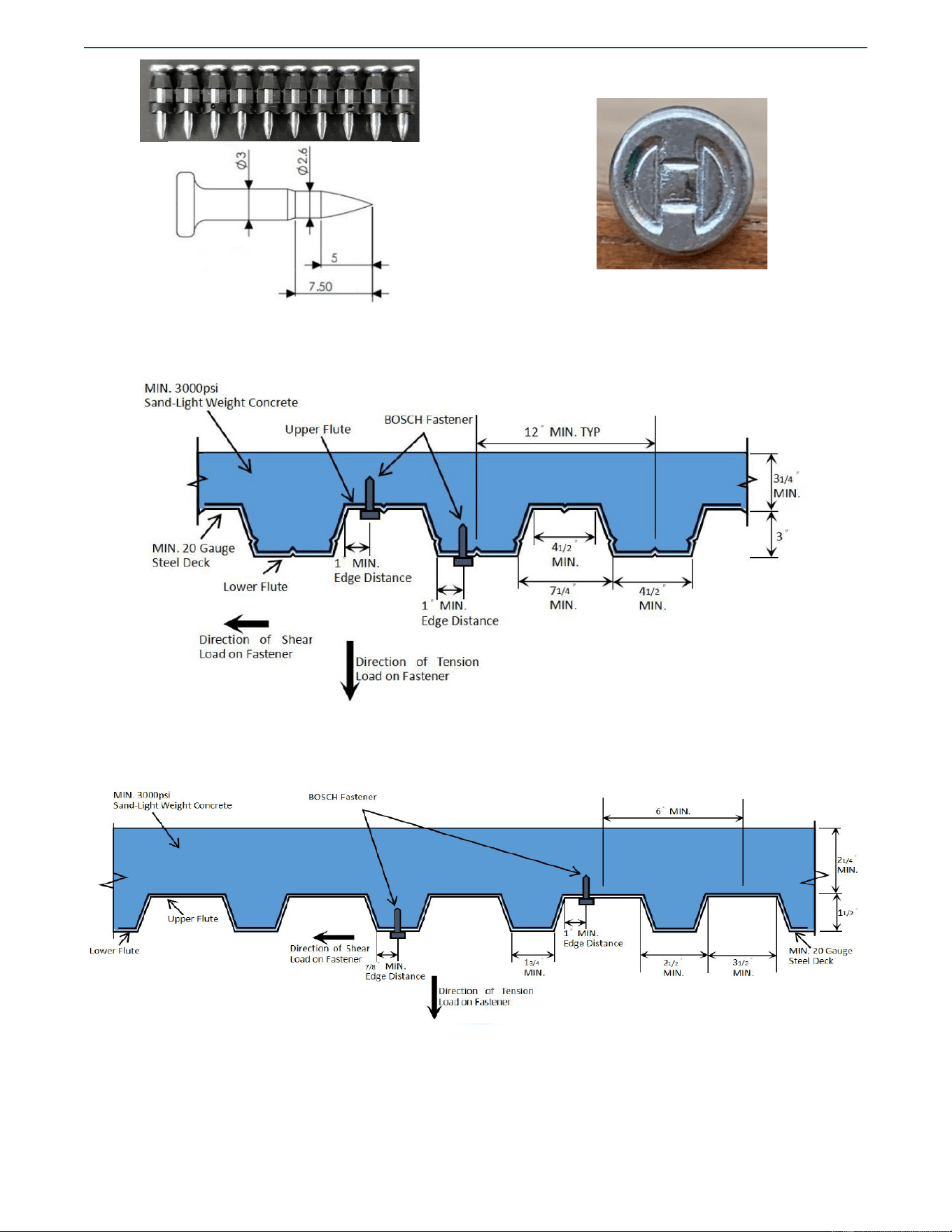
FIGURE 1—BOSCH NB FASTENER
FIGURE 2—BOSCH NK FASTENER
ESR-4893
|
Most Widely Accepted and Trusted Page 7 of 10
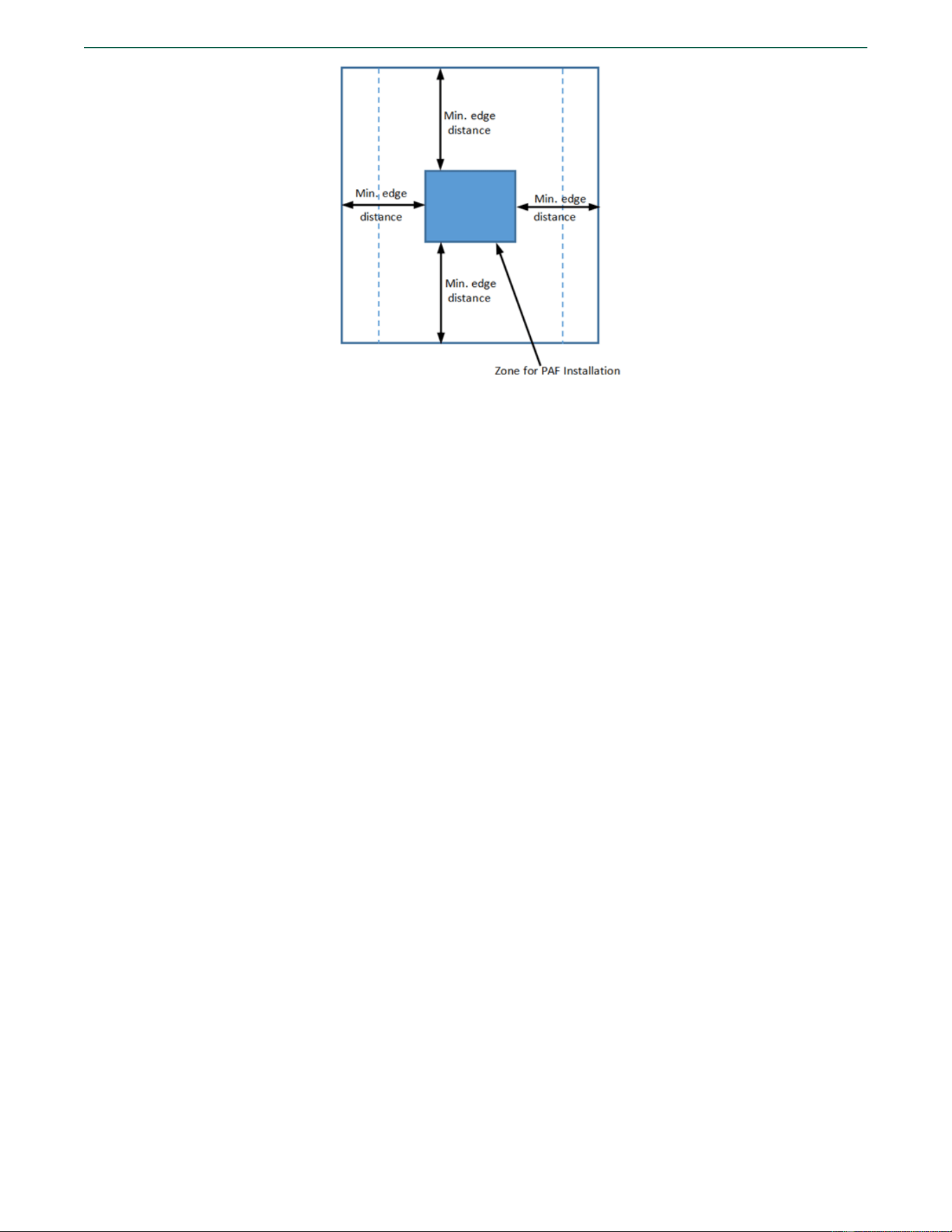
FIGURE 3—BOSCH NM FASTENER
FIGURE 4—BOSCH FASTENER HEAD MARKING
F
IGURE 5—BOSCH FASTENER LOCATIONS IN 3-INCH-DEEP COMPOSITE FLOOR DECK PANEL
F
IGURE 6—BOSCH FASTENER LOCATIONS IN 1
1
/
2
-INCH-DEEP B-DECK PANEL
ESR-4893
|
Most Widely Accepted and Trusted Page 8 of 10
FIGURE 7—ZONE FOR FASTENER INSTALLATION IN FACE SHELL OF CMU
ICC-ES Evaluation Reports are not to be construed as representing aesthetics or any other attributes not specifically addressed, nor are they to be construed
as an endorsement of the subject of the report or a recommendation for its use. There is no warranty by ICC Evaluation Service, LLC, express or implied, as
to any finding or other matter in this report, or as to any product covered by the report.
C
opyright © 2022 ICC Evaluation Service, LLC. All rights reserved. Page 9 of 10
I
CC-ES Evaluation Report
ESR-4893 LABC and LARC Supplement
Issued March 2022
This report is subject to renewal March 2023.
www.icc-es.org | (800) 423-6587 | (562) 699-0543 A Subsidiary of the International Code Council
®
DIVISION: 03 00 00—CONCRETE
Section: 03 15 00—Concrete Accessories
Section: 03 16 00—Concrete Anchors
DIVISION: 04 00 00—MASONRY
Section: 04 05 19.16—Masonry Anchors
DIVISION: 05 00 00—METALS
Section: 05 05 23—Metal Fastenings
DIVISION: 09 00 00—FINISHES
Section: 09 22 16.23—Fasteners
REPORT HOLDER:
ROBERT BOSCH TOOL CORPORATION
EVALUATION SUBJECT:
BOSCH FASTENERS
1.0 REPORT PURPOSE AND SCOPE
Purpose:
The purpose of this evaluation report supplement is to indicate that Bosch fasteners, described in ICC-ES evaluation report
ESR-4893, have also been evaluated for compliance with the codes noted below as adopted by the Los Angeles Department
of Building and Safety (LADBS).
Applicable code editions:
20
20 City of Los Angeles Building Code (LABC)
2020 City of Los Angeles Residential Code (LARC)
2.0 CONCLUSIONS
The Bosch fasteners, described in Sections 2.0 through 7.0 of the evaluation report ESR-4893, comply with the LABC Chapters
19, 21, 22, 23 and the LARC, and are subject to the conditions of use described in this supplement.
3.0 CONDITIONS OF USE
The B
osch fasteners described in this evaluation report supplement must comply with all of the following conditions:
• All applicable sections in the evaluation report ESR-4893.
• The design, installation, conditions of use and identification of theBosch fasteners are in accordance with the 2018
International Building Code
®
(IBC) provisions noted in the evaluation report ESR-4893.
• The design, installation and inspection are in accordance with additional requirements of LABC Chapters 16 and 17, as
applicable.
• Under the LARC, an engineered design in accordance with LARC Section R301.1.3 must be submitted.
• The allowable values listed in the attached report and tables are for the fasteners only. Connected members shall be
checked for their capacity (which may govern).
This supplement expires concurrently with the evaluation report issued March 2022.
ICC-ES Evaluation Reports are not to be construed as representing aesthetics or any other attributes not specifically addressed, nor are they to be construed
as an endorsement of the subject of the report or a recommendation for its use. There is no warranty by ICC Evaluation Service, LLC, express or implied, as
to any finding or other matter in this report, or as to any product covered by the report.
C
opyright © 2022 ICC Evaluation Service, LLC. All rights reserved. Page 10 of 10
ICC-ES Evaluation Report ESR-4893 FBC Supplement
Issued March 2022
This report is subject to renewal March 2023.
www.icc-es.org | (800) 423-6587 | (562) 699-0543 A Subsidiary of the International Code Council
®
DIVISION: 03 00 00—CONCRETE
Section: 03 15 00—Concrete Accessories
Section: 03 16 00—Concrete Anchors
DIVISION: 04 00 00—MASONRY
Section: 04 05 19.16—Masonry Anchors
DIVISION: 05 00 00—METALS
Section: 05 05 23—Metal Fastenings
DIVISION: 09 00 00—FINISHES
Section: 09 22 16.23—Fasteners
REPORT HOLDER:
ROBERT BOSCH TOOL CORPORATION
EVALUATION SUBJECT:
BOSCH FASTENERS
1.0 REPORT PURPOSE AND SCOPE
Purpose:
The purpose of this evaluation report supplement is to indicate that the Bosch fasteners addressed in ICC-ES evaluation report
ESR-4893, have also been evaluated for compliance with the codes noted below.
Applicable code editions:
2020 Florida Building Code—Building
2020 Florida Building Code—Residential
2.0 CONCLUSIONS
The Bosch fasteners, described in Sections 2.0 through 7.0 of ICC-ES evaluation report ESR-4893, comply with the Florida
Building Code—Building and the Florida Building Code—Residential. The design requirements must be determined in
accordance with the Florida Building Code—Building or the Florida Building Code—Residential, as applicable. The installation
requirements noted in ICC-ES evaluation report ESR-4893 for the 2018 International Building Code
®
meet the requirements
of the Florida Building Code—Building and the Florida Building Code—Residential.
Use of the Bosch fasteners for compliance with the High-Velocity Hurricane Zone provisions of the Florida Building Code—
Building or the Florida Building Code—Residential has not been evaluated, and is outside the scope of this supplemental
report.
For products falling under Florida Rule 61G20-3, verification that the report holder’s quality assurance program is audited by
a quality assurance entity approved by the Florida Building Commission for the type of inspections being conducted is the
responsibility of an approved validation entity (or the code official when the report holder does not possess an approval by the
Commission).
This supplement expires concurrently with the evaluation report issued March 2022.