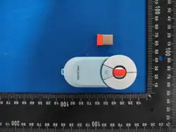
Product Description:
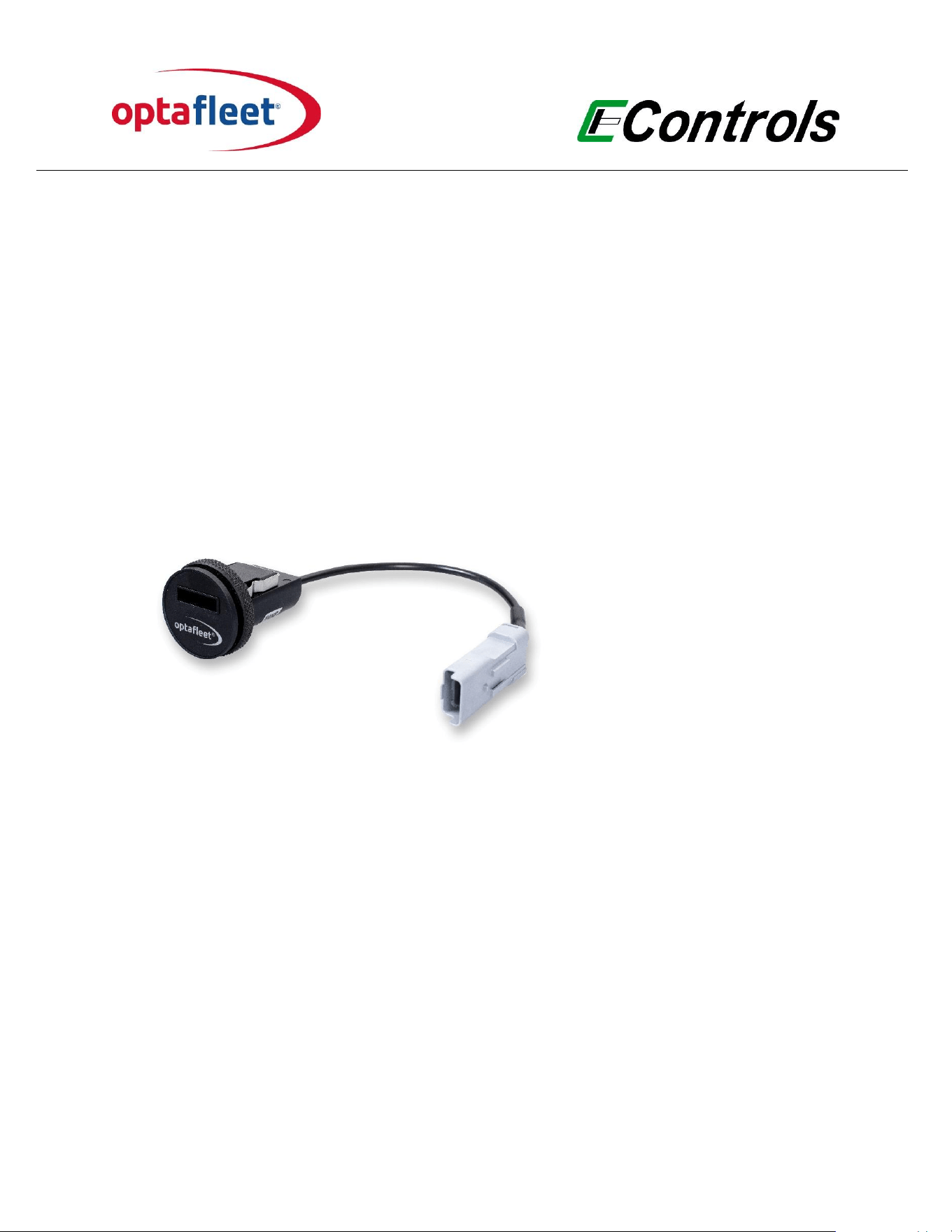
OptaFleet Key Reader
Model Number (HVIN):
FM 3010 2000
Model Name (PMN):
FM RFID key reader CAN Optaeet
FCC ID:
2BMQG-FM30102000
Manufacturer:
Econtrols Europe bv
Date of Issue:
April 20, 2026
Document number:
UIFM 3010 2000
Version document:
0.1
USER MANUAL
Key Reader

User Manual Key Reader
document
Version
Date
page
UIFM 3010 2000
0.1_draft
20-4-2026
1 of 5
1. Product Overview
The OptaFleet Key Reader is a RFID key reader that operates on radio frequency to provide
access control to the vehicle. Each driver will be provided with an electronic key. This key
contains a chip (Tag) with a unique code for each driver which can be read contactless.
The reader on the vehicle reads the code from the key and transmits this code to the ECU.
The vehicle ECU judges if the driver with this specic driver code can operate with the
vehicle.
The reader is equipped with LED and Buzzer to inform the driver about the status of the
access request. The Key Reader is also equipped with a magnet that the RFID Key Reader
can read with a hall sensor to identify the present of the key (useful as redundancy and in
the Optaeet low power strategy when it is possible to switch o the RFID antenna to
reduce the power consumption).
The antennas are integrated on the readers.
It contains:
• Internal transmitter for wireless communication
Technical Specications:
• Read frequency: 13.56MHz
• Temperature range : -40°C to +85°C
• Voltage : 5 V (from ECU)
• Max current.: 25 mA
• Protection class: IP67
• Communication: Proprietary CAN
• 2 RGB LEDs + Buzzer
• Robust & industrial design

User Manual Key Reader
document
Version
Date
page
UIFM 3010 2000
0.1_draft
20-4-2026
2 of 5
2. Package Contents
• 1 × Key Reader FM 3010 2000
• 1 × User Manual (this document)
3. Installation & Setup
Note: The installation has to be performed according to the information in this document by
trained and competent technicians.
Mounting of the Key Reader:
a. Mount the Key Reader in an accessible position on the dashboard. Ensure that the
reader is protected from the elements.
b. Drill diameter: 35 mm
c. Depth of Key Reader: 70 mm
d. Connect the gray 4-pin connector to the OptaFleet wiring loom.
Note: Electrical connections, wires, and looms must be correctly attached and protected
to prevent any form of friction with moving parts and contact with heat sources. Make use
of protective aids, such as heat shrink tubes, corrugated conduits, and waterproof
connectors.
Attention: Only power up the ECU after connecting the Key Reader to the wiring loom!
3.1 Powering the Device
The Key Reader is powered directly by the ECU. Power supply is 5 V.
Attention: Only power up the ECU after connecting the Key Reader to the wiring loom!

User Manual Key Reader
document
Version
Date
page
UIFM 3010 2000
0.1_draft
20-4-2026
3 of 5
3.2 Basic Operation
The Key Reader is equipped with a buzzer and red and green LEDs.
Turn on the ignition and insert the key into the reader.
If the key is recognized, the system is unlocked for further use and the green LED lights up.
If the key is not recognized, a beep sounds and the red LED lights up. The system remains
locked.
4. Wireless Operation
This product operates using 13.56MHz radio communication. Radio operation is automatic
and managed by the internal rmware. Users cannot modify transmission parameters such
as power level, frequency, or modulation.
5. Regulatory Notices
5.1 FCC Compliance Statement
This equipment has been tested and found to comply with the limits for a Class B digital
device, pursuant to part 15 of the FCC Rules. These limits are designed to provide
reasonable protection against harmful interference in a residential installation. This
equipment generates, uses and can radiate radio frequency energy and, if not installed and
used in accordance with the instructions, may cause harmful interference to radio
communications. However, there is no guarantee that interference will not occur in a
particular installation. If this equipment does cause harmful interference to radio or
television reception, which can be determined by turning the equipment o and on, the
user is encouraged to try to correct the interference by one or more of the following
measures:
• Reorient or relocate the receiving antenna.
• Increase the separation between the equipment and receiver.
• Connect the equipment into an outlet on a circuit dierent from that to which the
receiver is connected.
• Consult the dealer or an experienced radio/TV technician for help.
This device complies with Part 15 of the FCC Rules. Operation is subject to the following
two conditions: (1) this device may not cause harmful interference, and (2) this device must
accept any interference received, including interference that may cause undesired
operation. Please note that changes or modications not expressly approved by the party
responsible for compliance could void the user’s authority to operate the equipment.

User Manual Key Reader
document
Version
Date
page
UIFM 3010 2000
0.1_draft
20-4-2026
4 of 5
Note: Any changes or modications not expressly approved by the party responsible for
compliance could void the user's authority to operate this equipment.
5.2 FCC RF Exposure Statement
This equipment complies with FCC radiation exposure limits set forth for an uncontrolled
environment. This transmitter must not be co-located or operating in conjunction with any
other antenna or transmitter. In order to avoid the possibility of exceeding the FCC radio
frequency exposure limits, this equipment should be installed and operated with minimum
distance 20 cm (7.9 inches) between the antenna and your body during normal operation.
Users must follow the specic operating instructions for satisfying RF exposure
compliance.
6. Certications and Approvals
• FCC ID: 2BMQG-FM30102000
• Complies with applicable FCC Part 15.
7. Safety and Maintenance
• Do not disassemble or modify the product.
• Do not expose the device to water, re, or excessive heat.
• Only use supplied or certied accessories.
• Clean with a soft dry cloth only.

User Manual Key Reader
8. Support & Contact Information
For product support, warranty information, or replacement parts, please contact:
Econtrols Europe bv
Distributieweg 9
2645 EG Delfgauw
Phone: +31 (0) 15 274 25 50
Email: info@econtrols-europe.com
Website: www.optaeet.com
document
Version
Date
page
UIFM 3010 2000
0.1_draft
20-4-2026
5 of 5