
ŔŔŕĮŔŕĶıŇĮijĴı
STRIDER SERIES
Elevated performance, at ease
Dual +12V rails with 32A maximum output
Maximum efficiency up to 80%
Support dual PCI-E 6pin connectors
Silent running 120mm Fan with 20dBA
Modular cable design
500W continuous power output (230Vac input only)
Active PFC
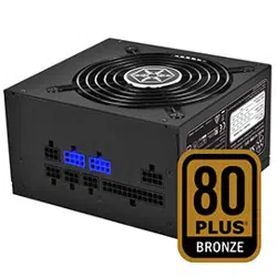
SilverStone Strider ST50F-230
ATX12V Switching Power Supply
With Active PFC
PS/2 500W
230Vac only
1. Input Requirements
1.1 Input Voltage
The power supply shall be operated at universal input voltage defined in the following table.
1.2 Frequency
The input frequency range is from 50Hz to 60Hz.
1.3 Inrush Current
The max inrush current is 8A for 230VAC
lnput Voltage Nom.Min. Max.
264Voltage 180 200-240
01
1.3.1 Cold Start
1.3.2 Warm Start
1.4 AC Input Current
1.5 Efficiency
The maximum efficiency >80% in the typical load and 230 Vac input voltage conditions.
2. Output Requirements
2.1 Output Regulations
Note:
(1) The above voltage range should also include ripple and noise.
(2) The output voltage should be measured at the terminals of output connector
.
LimitsConditions
No component over stress or damage should
occur to the power supply.
Input fuse shall not blow up .
No component over stress or damage should
occur to the power supply.
Input fuse shall not blow up .
230VAC, full load.
25
C ambient.
UnitsMAXAC Input
8230V
AMPS
MIN
+5.00
+12.00
+12.00
-12.00
+4.75
+11.40
+11.40
-10.80
Range Normal MAX Units
Volts
Volts
Volts
Volts
Output Voltage
5%
+12.60
+5.25
+12.60
-13.20
+5V
+12V1
+12V2
-12V
LimitsConditions
Turn off at 264VAC full load for 1 sec then
turn on at the peak of the input voltage cycle
at 25 C ambient.
5%
5%
10%
5%
5%
Volts
Volts+3.30
+5.00
+3.14
+4.75
+3.46
+5.25
+3.3V
+5Vsb
ᑻ
ᑻ
±
±
±
±
±
±
STRIDER SST-ST50F-230
02
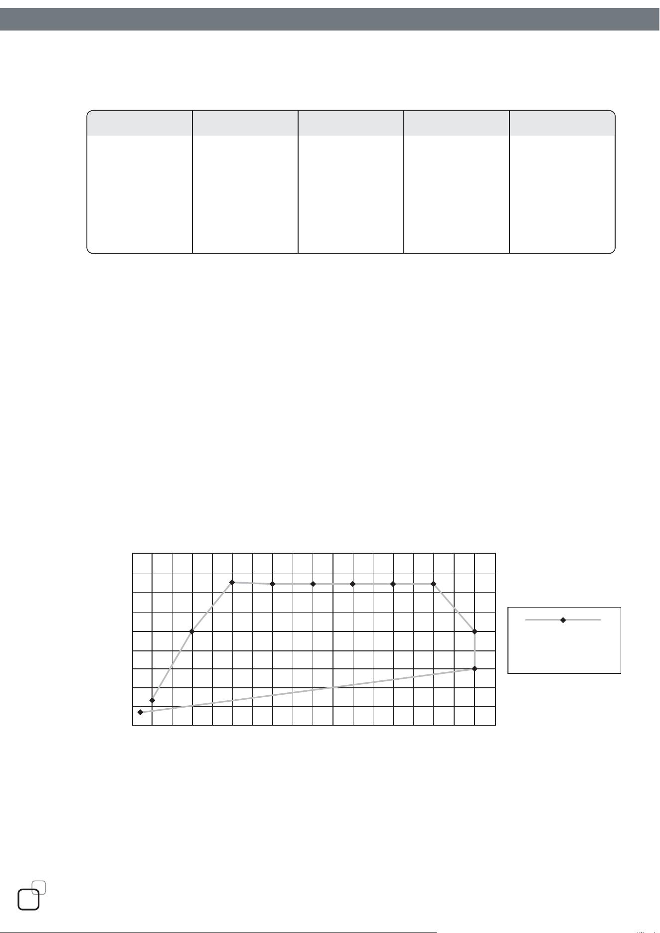
2.2 DC Load Requirements
Notes:
(1) The maximum continuous total DC output power shall not exceed 500 Watts.
(2) The maximum continuous combined load on +5V and +3.3V outputs shall not exceed 150 Watts.
combined load on +12V1 and +12V2 outputs shall not exceed 384 Watts.
The maximum continuous combined load on +5V, +3.3V and +12V1,+12V2 outputs shall not
exceed 488 Watts.
(3)
2.3 Cross Regulation
The DC loads shall remain within the ranges specified in 2-2 DC Load Requirements and
the DC output voltages also shall remain within the regulation ranges specified in 2-1
Output Regulation when measured at the load end of the output connectors.
2.4 +5V standby voltage
The +5Vsb is on whenever the AC power is present.
1.0
1.0
1.0
0.0
1.0
0.1
Min
30
18
18
0.8
25
2.5
MaxOutput Voltage
+5V
+12V1
+12V2
-12V
+3.3V
+5Vsb
Units
Amps
Amps
Amps
Amps
Amps
Amps
Nom
15
8
8
0.4
12.5
1
0
20
40
60
80
100
120
140
160
180
25 50 100 150 200 250 300
500W
Cross Regulation
(+5V rail +3.3V vs. 12V)
12V power (watts)
5V +3.3V power (watts)
Combined Power
350 385
(5V rail + 3.3V rail)
03
2.5 DC Output Voltage Ripple and Noise
Note :
(1) The measurements should be made by crossing a 10uF/ electrolytic and a 0.1uF
ceramic disk capacitors at each output with measuring bandwidth from DC to 20 MHz. If
ambient temperature is under 20 C or over 30 C, the
AC input should be normal input.
2.6 Total Output Power
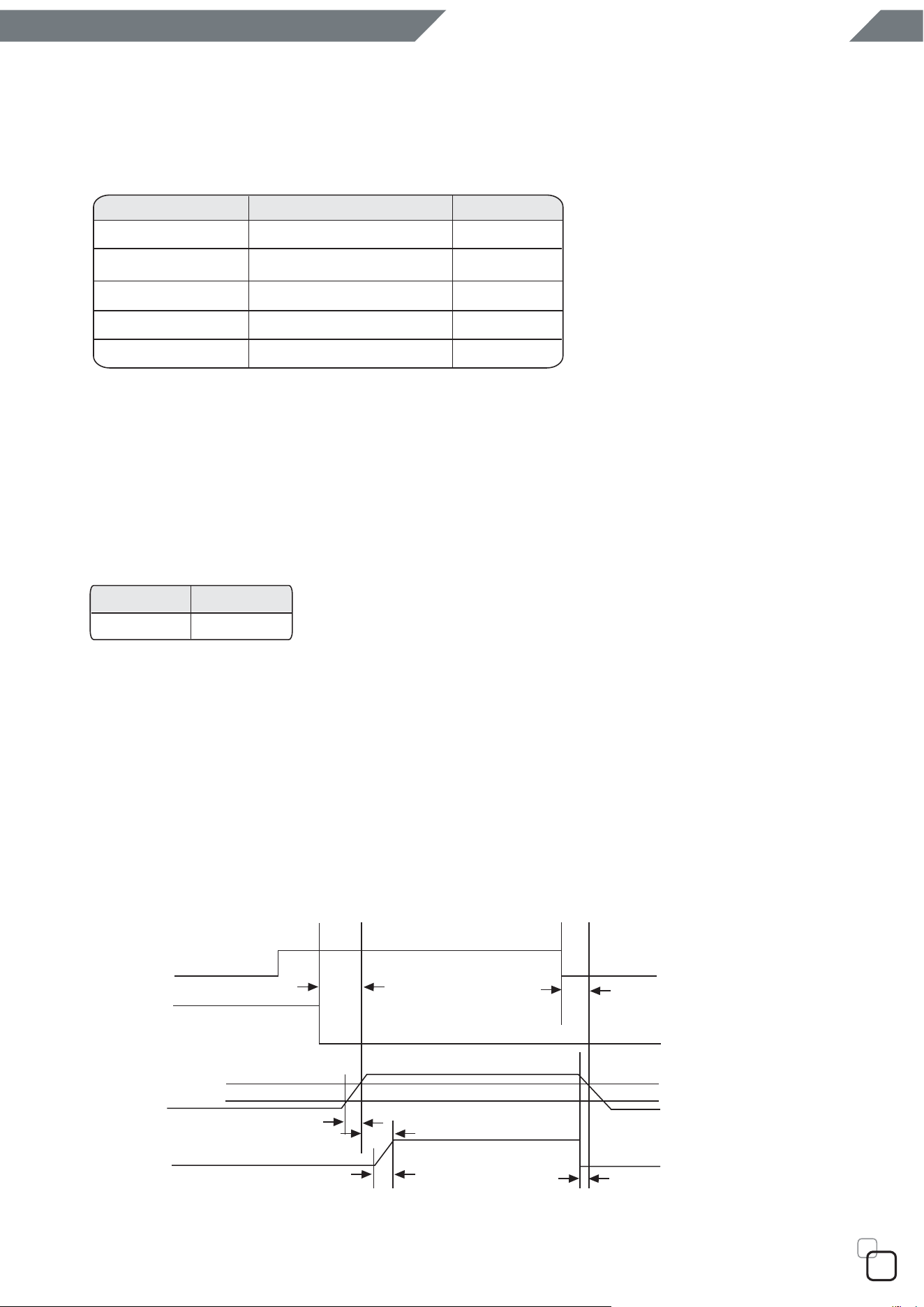
2.7 Remote ON/OFF control
The power supply outputs shall be enabled with an active-low TTL signal.
When TTL signal is low , the DC outputs are to be enabled.
When TTL signal is high or open circuited, the DC outputs are to be disabled.
Electronic means or a mechanical switch may activate the TTL signal.
After the TTL signal is active high, must wait for 3 seconds before active low again.
2.8 Power Sequence
UnitsRipple & Noise MaxOutput Voltage
50
+5V
mV
+12V1~2
-12V
+3.3V
+5Vsb
120
120
50
50
mV
mV
mV
mV
UnitsMAX
500
Watts
T1
T2
T5
On
Off
T3
T4
T6
AC IN
PS-ON
95%
10%
+12V
+5V
+3.3V
O/P’s
PG#
ᑻ
ᑻ
STRIDER SST-ST50F-230
04
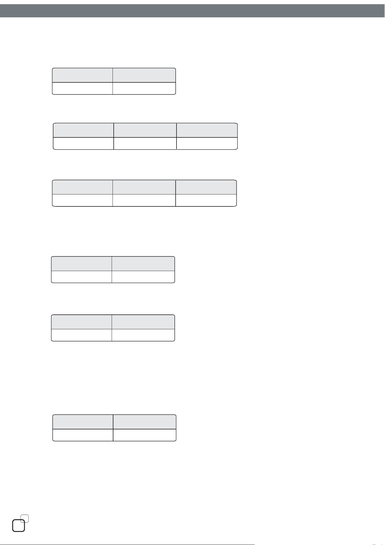
2.9 Power On Time (T1)
2.10 Rise Time (T2)
2.11 Power Good Delay Time (T3)
The test environment is 25 C condition @ normal input.
2.12 Power Good Rise Time (T4)
2.13 Hold Up Time (T5)
The test environment is 25
C & full load condition @ nominal input.
2.14 Power Fail Signal (T6)
Power good signal shall go to a down level 1ms before +5V output voltage falls below the
regulation limits during PS-ON signal pull high.
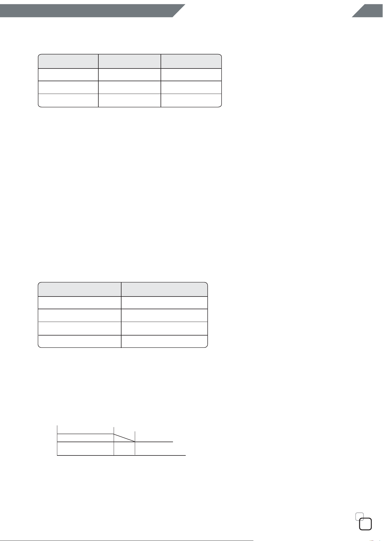
3. Protections
3.1 Over Voltage Protection
When the DC outputs (+5V, +12V, +3.3V) have over voltage condition, the power supply
shall provide latch mode over voltage protection.
MAX Units
500 ms
MIN MAX
120
Units
ms
MIN MAX
100 500
Units
ms
MAX Units
10 ms
MIN Units
15 ms
MIN Units
1.0
ms
05
3.2 Short Circuit Protection
A short circuit placed to ground shall cause no damage or power supply shall be shutdown.
(The contact resistance is 0.05 ohm when the outputs short circuit.)
3.3 Protection Reset
When the power supply latches into shutdown condition due to a fault on an+5V,+3.3V,+12V1,+12V2
output( OVP, UVP,OCP ), the protection shall reset after the fault has been removed, use remote
on/off control or recycle the AC power again for a typical of 5 seconds.
3.4 Over
3.6 Over Current Power
shoot Protection
Any output overshoot at turn on shall be less than 15% of the normal output value
(with resistive load) as described in sec. 2.1.
At 230Vac input the power supply will shut down all DC output within 110% to 150% of full load.
3.5 Over
power Protection
4. ENVIRONMENT
4.1 Operation/Storage Temperature Range
Operation : 5 Cto 50
C (normal input)
Storage : -40 C to 70
C
4.2 Humidity (none condensing)
Operation : 20% to 85% RH (normal input)
Storage : 10% to 95% RH
DC output MAX
+12V1~2
15.5
Units
V
+5V
+3.3V 4.6
V
6.5
V
OUTPUT VOLTAGE
+5 V 45 A
Max over current limit
+12 V1
+12 V2
+3.3 V
27 A
37.5 A
27 A
Load
100%
80%
50
C
25
C
STRIDER SST-ST50F-230
06

6. EMI Requirements
7. Dielectric Voltage Withstand (HI-POT)
The power supply shall withstand for 3 seconds without breakdown the application of an
1800Vac-supply voltage applied between both input line and chassis (15mA AC Cutoff current).
Isolating transformers shall similarly withstand 4242Vdc applied between both primary and
secondary windings for a minimum of one minute.
8. PFC
Active Power Factor Correction, complies with EN 61000-3-2: 2000, Class D.
9. Electrostatic Discharge (ESD)
Comply with IEC 61000-4-2.
10. EFT/ Burst
Comply with IEC 61000-4-4
Comply with IEC 61000-4-5.
The power supply shall have a minimum mean time between failure greater than 100,000 hours at
continuous operation of 100% load and an ambient temperature of 25 C
1
11. Surge
Applying 230 Vac + 10% input voltage and maximum load (80%) for this product in 45 + 5 C chamber.
12. Burn-In
13. M.T.B.F.
A6-1.CE
5. Safety
5-1. TUV EN 60950-1
5-2. CB
07
O
O
14.1 Physical Dimension
150 mm (W) × 86 mm (H) × 160 mm (D)
14.2 Connectors Define
14. MECHANICAL REQUIREMENTS
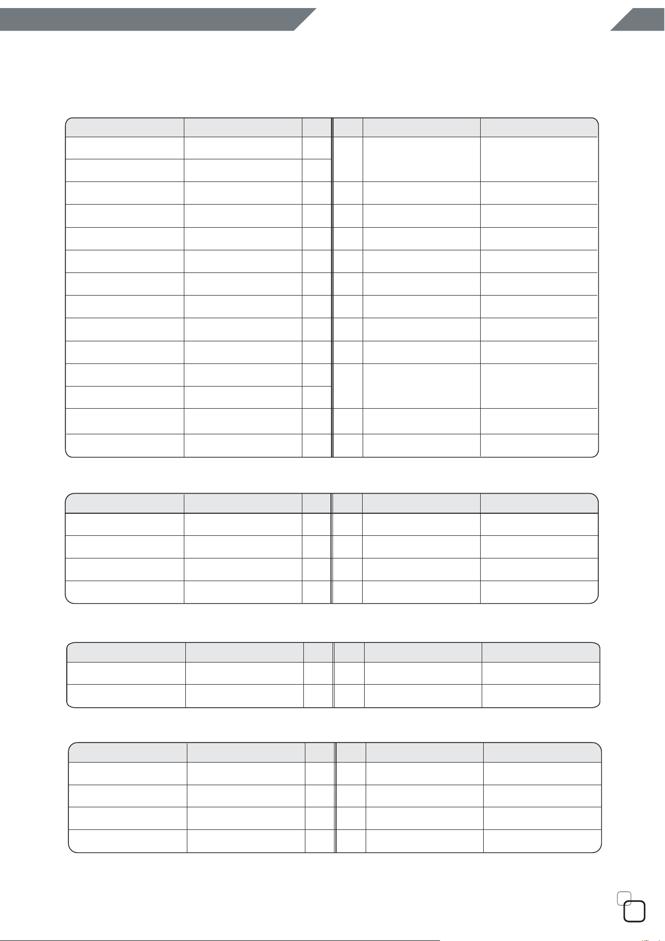
EPS 12V 8PIN connector
Pin
1
2
3
4
5
6
7
8
9
10
11
12
13
13
14
15
16
17
18
19
20
21
22
23
24
Signal Pin Signal 18AWG wire
Orange
Orange
Orange
Green
Blue
Black
Black
Black
Black
Black
+3.3V
+3.3V
+3.3Vsense
-12VDC +3.3V
+3.3V
Orange
Orange
Black
Red
Black
Black
Grey
Purple
Yellow
Yellow
Red
Red
Red
Red
COMCOM
COM
COM
COM
COM
N/CWhite
+5VDC
+5VDC
+5VDC
PS-ON +5VDC
+5VDC
COM
COM
PWRGOOD
+5Vsb
+12V1
+12V1
Yellow
M/B 24PIN connector
Red
+5Vsense
22
Yellow
Yellow
Yellow
Yellow
Yellow
ATX 12V 4PIN(4+4PIN EPS 12V in split mode)
GND
GND
Yellow
Red
+5VDC
+5VDC
Yellow
Red
4PIN peripheral connector (HDD)
4PIN floppy connector (FDD)
PinSignal Pin Signal
+12V1
+12V1
+12V2
+12V2
1
2
3
4
5
6
7
8
COM
Black
COM
Black
COM
Black
COM
Black
PinSignal Pin Signal
Black
Black
1
2
3
4
+12V1
+12V1
Pin
Signal Pin Signal
Black
Black
+12V1
+12V1
COM
COM
COM
COM
Black
Black
1
2
3
4
1
2
3
4
STRIDER SST-ST50F-230
08
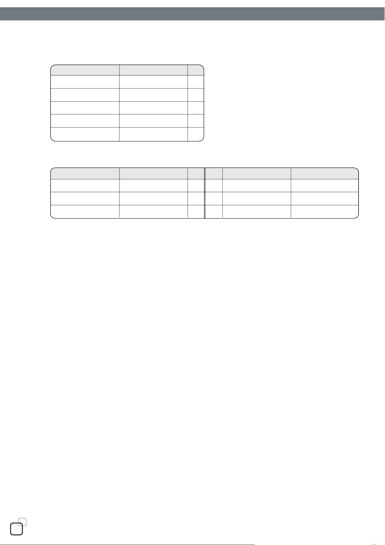
Pin
1
2
3
Signal Pin Signal
Black
Black
Black
+12V2
+12V2
+12V2
COM
COM
COMYellow
Pin
5
4
3
2
1
Signal
Black
Yellow
Black
Red
COM
+12V1
+5V
COM
+3.3V
Orange
Yellow
Yellow
4
5
6
SATA connector
6PIN PCI Express Connector
09

10
STRIDER SST-ST50F-230
November, 2008
NO.G11209100