SERIENNUMMER VOM KARTON AUFBRINGEN
Seriennr.
MODELL-NR.
BRENG HET SERIENUMMER VAN DE DOOS AAN
Serienr.
MODELNR.
NANESTE SÉRIOVÉ ČÍSLO Z KARTONU
Sériové číslo:
ČÍSLO MODELU:
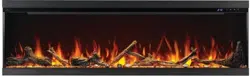
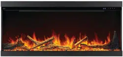
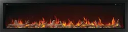
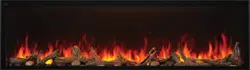
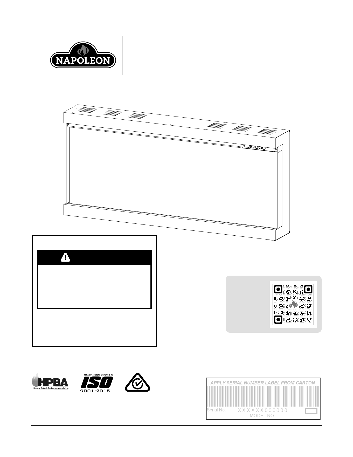
Astound FlexMount Series
(NEFL50AB-AU Illustrated)
NEFL50AB-AU / NEFL62AB-AU / NEFL74AB-AU
CERTIFIED TO
AS/NZS 60335.2.30:2023;
AS/NZS 60335.1:2020+ A1:2021
FOR INDOOR USE ONLY
Wolf Steel Ltd., 24 Napoleon Rd., Barrie, ON, L4M 0G8 Canada
103 Miller Drive, Crittenden, Kentucky, 41030 USA
www.napoleon.com · [email protected]
W415-10008161 | A-0
INSTALLER: Leave this manual with the appliance.
CONSUMER: Keep this manual for future reference.
FIRE OR EXPLOSION HAZARD
If the information in these instructions
are not followed exactly, a fire or
explosion may result causing property
damage, personal injury, or loss of life.
* Do not store or use gasoline
or other flammable vapors and liquids in
the vicinity of this or
any other appliance.
SAFETY INFORMATION
WARNING
INSTALLATION AND
OPERATION MANUAL
To register
your
appliance,
scan here.
EN
safety information
2 | W415-10008161 | A-0
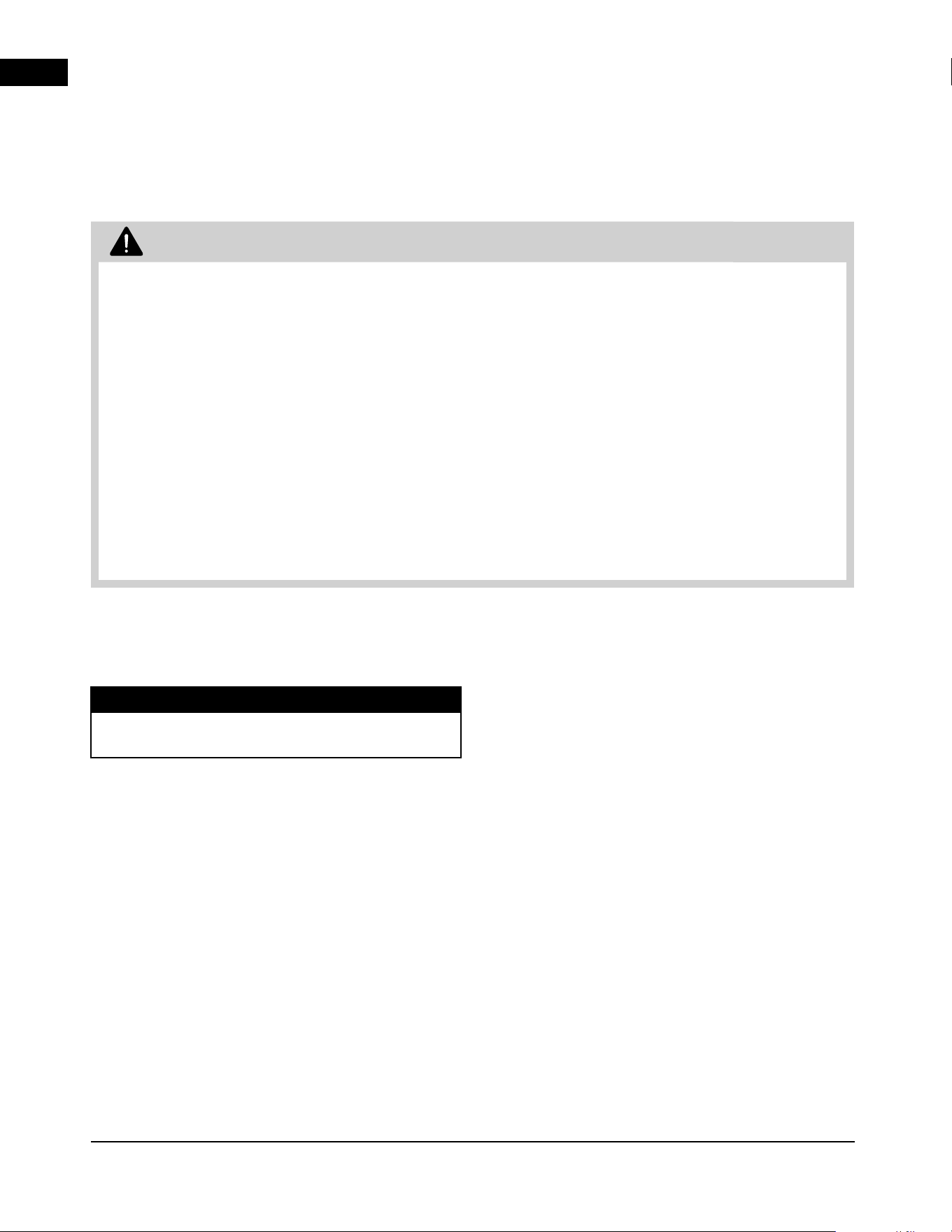
WARNING
• If equipped with a heater, this appliance can
be hot when operated and can cause severe
burns if contacted.
• Do not operate appliance before reading and
understanding operating instructions. Failure
to operate appliance according to operating
instructions could cause fire or injury.
• Do not install damaged, incomplete or
substitute components.
• Do not burn wood or other materials in
this appliance.
• All electric appliances have hot and arcing or
sparking parts inside. Do not use it in areas
where a gas line, paint or flammable liquids
are present.
• Any safety screen or guard removed for
servicing must be replaced prior to operating
the appliance.
• It is imperative that the control compartments,
circulating blower and its passageway in the
appliance are kept clean. The appliance should
be inspected before use and at least annually
by a qualified service person. More frequent
cleaning may be required due to excessive
lint from carpeting, bedding material, etc. The
appliance area must be kept clear and free
from combustible materials, gasoline and other
flammable vapors and liquids.
• Under no circumstances should this
appliance be modified.
• Do not use this appliance if any part has been
under water. Immediately call a qualified
service technician to inspect the appliance
and to replace any part of the control system
which has been under water.
• If equipped with a glass door, do not operate
the appliance with the glass door removed,
cracked or broken. Replacement of the glass
should be done by a licensed or qualified
service person. Do not strike or slam shut the
appliance glass door.
• Keep the packaging material out of reach
of children and dispose of the material in a
safe manner. As with all plastic bags, these
are not toys and should be kept away from
children and infants.
• Servicing should be done only while the
appliance is disconnected from the power
supply circuit.
• Always unplug appliance when not in use.
• Do not operate this appliance with a
damaged cord or plug after the appliance
malfunctions, has been dropped
or damaged in any manner. Return
appliance to authorized service facility
for examination, electrical or mechanical
adjustment, or repair.
• Do not use outdoors.
• When installing this appliance in a room
where water is present, the installation must
comply with codes recognizing the increased
hazard of electrical shock and electrocution.
• Do not run cord under carpeting. Do not
cover cord with throw rugs, runners, or the
like. Arrange cord away from traffic area and
where it will not be tripped over.
• Connect to properly grounded outlets only.
• Do not insert or allow foreign objects to
enter any ventilation or exhaust opening as
this may cause an electric shock or fire, or
damage the appliance.
• It is normal for your electric appliance to
produce noise, especially when installed
in a quiet space such as a bedroom.
Note:
This appliance in NOT suitable for installation in a
bathroom.
EN
safety information
A-0 | W415-10008161 | 3
WARNING
• To prevent a possible fire, do not block air
intakes or exhaust in any manner. Do not
use on soft surfaces, like a carpet, where
openings may become blocked.
• Always plug appliances directly into a wall
outlet/receptacle. Never use an extension
cord or relocate cable power tap (outlet/
power strip).
• These appliances are tested and listed
for use only with the optional accessories
listed in these instructions. Use of optional
accessories not specifically tested for this
appliance could void the warranty and/or
result in a safety hazard.
For appliances equipped with a heater:
• Risk of burns. Power to the appliance should
be turned off and the appliance allowed to
cool before servicing. To disconnect power to
the appliance, turn controls to off, then remove
plug from outlet.
• Young children should be carefully
supervised when they are in the same
room as the appliance. Toddlers, young
children and others may be susceptible
to accidental contact burns. A physical
barrier is recommended if there are at risk
individuals in the house. To restrict access to
an appliance or stove, install an adjustable
safety gate to keep toddlers, young children
and other at risk individuals out of the room
and away from hot surfaces.
• Clothing or other flammable material should
not be placed on or near the appliance.
• Due to high temperatures, the appliance
should be located out of traffic and away from
furniture and draperies.
• Ensure you have incorporated adequate
safety measures to protect infants/toddlers
from touching hot surfaces.
• Even after the appliance is off, the glass and/
or screen will remain hot for an extended
period of time.
• Check with your local hearth specialty dealer
for safety screens and hearth guards to protect
children from hot surfaces. These screens and
guards must be fastened to the floor.
• Ensure clearances to combustibles are
maintained when building a mantel or shelves
above the appliance. Elevated temperatures
on the wall or in the air above the appliance
can cause melting, discolouration or damage
to decorations, a TV or other electronic
components.
• The appliance is not to be used by persons
(including children) with reduced physical,
sensory or mental capabilities, or lack of
experience and knowledge, unless they have
been given supervision or instruction.
• Children must be supervised not to play with
the appliance.
• Heater must not be located immediately
below a socket-outlet.
• If the supply cord is damaged, it must be
replaced by the manufacturer, its service
agent or similarly qualified persons in order to
avoid a hazard.
CAUTION
In order to avoid
overheating, do not cover the heater.
CAUTION
In order to avoid a hazard
due to inadvertent resetting of the thermal
cut-out, this appliance must not be supplied
through an external switching device, such
as a timer, or connected to a circuit that is
regularly switched on and off by the utility.
EN
table of contents
4 | W415-10008161 | A-0
1.0 general information 6
1.1 dimensions 6
1.2 listing approvals 7
1.3 general instructions 7
1.4 unpacking and testing the appliance 8
1.5 hardware list 9
1.6 rating plate information 9
2.0 installation 10
2.1 overview 10
2.2 minimum mantel clearances 13
2.3 wall mount installation 14
2.4 partial recessed installation 17
2.4.1 rough framing 17
2.4.2 unit preparation 18
2.5 built in application 19
2.5.1 trim / panel installation 19
2.5.2 rough framing 21
2.5.3 recessed installation 22
3.0 electrical information 23
3.1 240 V hard-wiring 24
3.2 optional wall-mount controller installation 24
4.0 finishing 25
4.1 finishing materials 25
4.2 media installation 26
4.2.1 beach fire logs and woodland media kit 26
4.3 front glass installation and removal 27
5.0 wiring diagram 28
5.1 NEFL50AB-AU wiring diagram 28
5.2 NEFL62AB-AU wiring diagram 29
5.3 NEFL74AB-AU wiring diagram 30
6.0 operation 31
6.1 operating control panel 31
6.2 operating remote control 32
6.3 operating optional wall mount controller 35
The information throughout this manual is believed to be correct at the time of printing. Wolf Steel Ltd.
reserves the right to change or modify any information within this manual at any time without notice.
Changes, other than editorial, are denoted by a vertical line in the margin.
note:

EN
table of contents
A-0 | W415-10008161 | 5
7.0 napoleon connectivity 36
7.1 adding device 37
7.2 using the app 39
7.2.1 power setting 39
7.2.2 heat setting 39
7.2.3 ember bed setting 40
7.2.4 flame setting 40
7.2.5 accessory lights settings 41
7.2.6 timer settings 41
8.0 maintenance 42
8.1 cleaning 42
8.2 heater lockout switch 42
9.0 replacement parts 43
9.1 NEFL50/62/74AB-AU 44
10.0 troubleshooting 46
11.0 warranty 48
EN
general information
6 | W415-10008161 | A-0
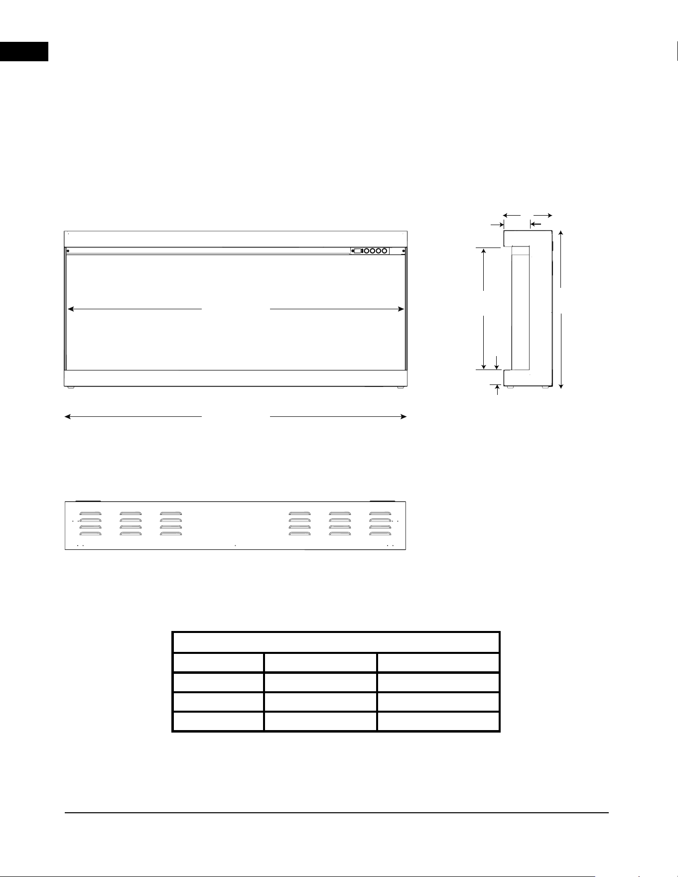
Dimensions
Model No. A (inside width) B (outside width)
NEFL50AB-AU
1262 mm 1270 mm
NEFL62AB-AU
1567 mm 1575 mm
NEFL74AB-AU
1872 mm 1880 mm
front view side view
top view
1.0 general information
1.1 dimensions
23”
(585 mm)
18”
(457mm)
7 1/8”
(181 mm)
2 3/8”
(60 mm)
3 3/4”
(95 mm)
A
B
EN
general information
A-0 | W415-10008161 | 7
1.2 listing approvals
This appliance has been tested in accordance with the
SAA Standards for fixed and location-dedicated electric
room appliances in Australia and New Zealand.
If you need assistance during installation, please
contact your local dealer.
1.3 general instructions
• Prior to plugging your appliance into an electrical
outlet, verify that the house circuit breakers for
the outlet are on.
• The appliance may emit a slight, harmless odour
when first used. This odour is normal and it is
caused by the initial heating of internal appliance
elements and will not occur again.
• If your appliance does not emit heat when called for,
consult the “operation” section of this manual for
further information.
This electric appliance meets the construction
and safety standards of H.U.D. for application in
manufactured homes when installed according to
these instructions.
As with most electronic devices, your new electric
appliance has been designed to operate at
temperatures between 5°C and 35°C. During the
colder winter months, allow the appliance
to reach room temperature before turning it on.
Description
Electric Appliance
Type
Wall mounted Electric fireplace
Voltage
240V AC
Watts
MAX 1900W
Amps
Dedicated 10 AMP Grounded Circuit
note:
This appliance must be electrically wired and grounded in accordance with local codes.
EN
general information
8 | W415-10008161 | A-0
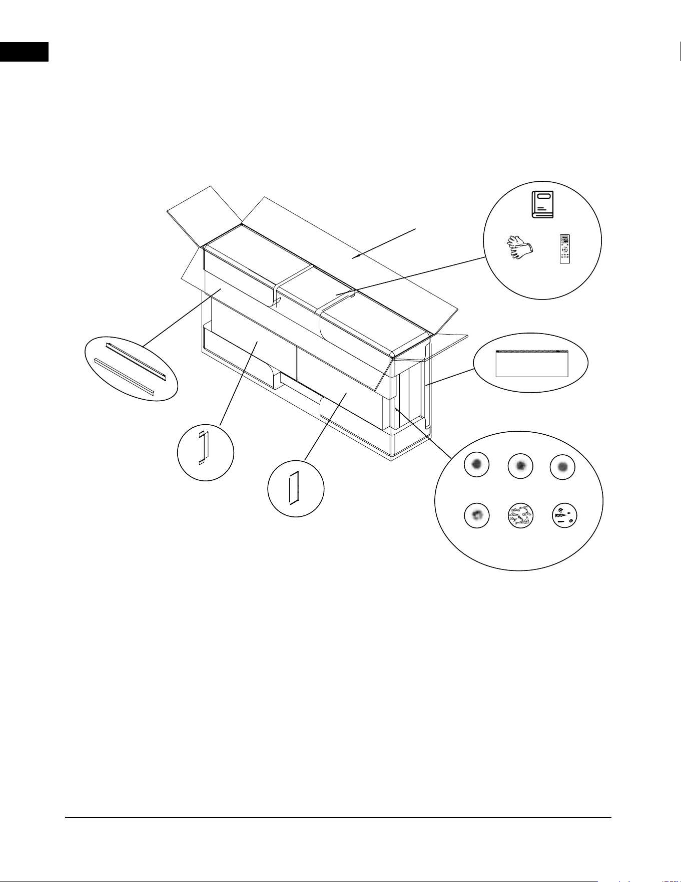
Outer Box
Front Glass
SIDE FINISH
PANEL
SIDE FINISH
TRIM
TOP BOTTOM
FINISH TRIM
Smokey
gem glass
Rusty iron
glass
Logs
(Quantities
vary by
appliance size)
Charcoal
ACCESSORY
Box
ACCESSORY Box
Rocks
Hardware
Kit
Manual
Pair of
Gloves
Remote
1.4 unpacking and testing the appliance
Ensure to unpack this appliance with 2 people. Reference the hardware list (see “hardware list” section)
to prepare for installation.
EN
general information
A-0 | W415-10008161 | 9
The rating plate must remain
with the appliance at all times.
It must not be removed.
WOLF STEEL LTD.
SPECIFICATIONS: BLACK LETTERING ON SILVER BACK-
GROUND. MINIMUM FONT SIZE TO BE MINIMUM OF 8.5 PT
(3.2mm)
SERIAL NUMBERS TO BE ASCENDING FROM NEFLXX-
AB-AU 000000 (INSERT APPLIANCE SIZE FOR "XX")
TITLE: RATING PLATE, NEFL50-62-74AB-AU
MATERIAL: CLASS IIIA-2 PERMANENT LEXAN ADHESIVE LABEL,
MINIMUM THICKNESS 0.1MM, NON WATER SOLUBLE ADHESIVE CAPA-
BLE OF WITHSTANDING A MAXIMUM TEMPERATURE OF 175°F (79°C).
REVISION NOTES: --0 07.25.2025 Initial. - JS
LABEL SIZE: 6”w x 2.75”h
DRAWING: W385-10008177
MODEL(S): NEFL50-62-74AB-AU
CREATION DATE: 07.25.2025
APPROVED BY: J. WHITEHEAD
CERTIFIED UNDER AUSTRALIAN AND NEW ZEALAND STANDARD:
AS/NZS 60335.2.30:2023; AS/NZS 60335.1:2020+ A1:2021
ELECTRIC FIREPLACE. SUITABLE FOR BEDROOM AND BED-SITTING ROOM
INSTALLATION. SUITABLE FOR MOBILE HOME INSTALLATION.
VOLTAGE: 220-240VAC
FREQUENCY: 50Hz
POWER: 1750-1950W
DATE CODE:
DESIGNED IN NORTH AMERICA BY WOLF STEEL LTD.
MADE IN CHINA
WOLF STEEL LTD.
24 NAPOLEON ROAD,
BARRIE, ON, L4M 0G8 CANADA
SERIAL NUMBER
NEFLXXAB-AU
MODEL
NEFL50AB-AU NEFL62AB-AU NEFL74AB-AU
W385-10008177
CERTIFICATE NO.:
SAA-251251-EA
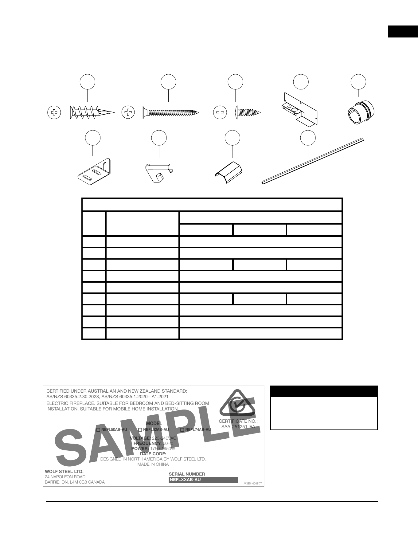
Hardware List
Item Description
Quantity
NEFL50AB-AU NEFL62AB-AU NEFL74AB-AU
A
45 mm Drywall anchors 7
B
#6 35 mm Wood Screws 7
C
ST4-12 Metal screws 18 18 24
D
Junction box cover plate 1
E
Strain relief 1
F
Bracket 5 5 7
G
Cord Corner 2
H
Cord Cover Connector 2
I
Cord Cover 2
1.5 hardware list
1.6 rating plate information
The below illustration is for reference only. Refer to the appliance rating plate for accurate information.
note:
A B C D E
I
F
G H
SAMPLE
EN
installation
10 | W415-10008161 | A-0
This appliance is designed as a Wall Mounted appliance
that can also be recessed into an enclosure. Select a
suitable location that is not susceptible to moisture and
is away from drapes, furniture and high traffic areas.
Due to the many different materials used on different
walls, it is highly recommended that you consult your
local builder before you install this appliance.
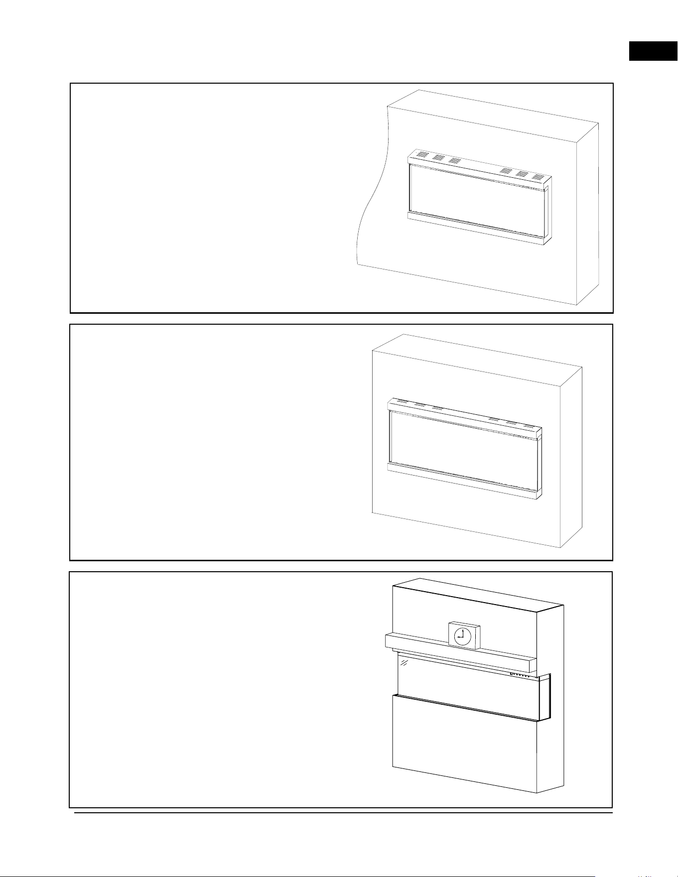
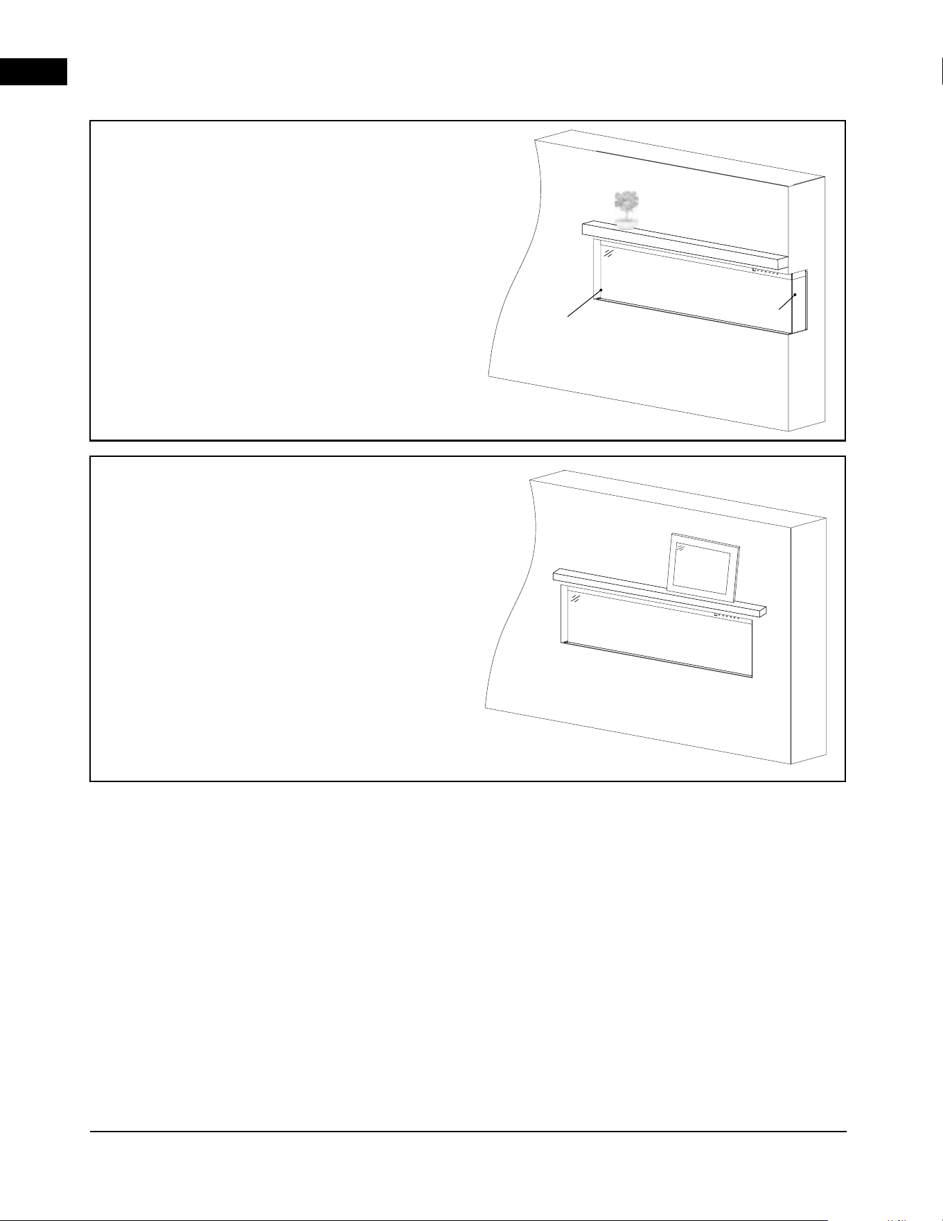
This appliance can be installed in multiple applications.
This appliance can be hung on the wall, partially in the
wall, fully in the wall (single sided) at the end of a wall
(2 Sided) or in a bay “bump out” enclosure (3 Sided).
1. Select a location that is not prone to moisture
and is located at least 36” (91.4 cm) away from
combustible materials such as curtain drapes,
furniture, bedding, paper, etc.
2. The installation consists of 6 major steps, rough
framing, unit installation, hard-wiring, finishing
material, fireplace log media, then glass and trim
installation. Each step must be completed before
advancing to the next stage to achieve a seamless
installation and to avoid damaging the product
or enclosure.
2.0 installation
2.1 overview
• Risk of fire! The power cord must not be
pinched against a sharp edge. Secure cord to
avoid tripping or snagging to reduce the risk
of fire, electric shock, or personal injury. Do
not run cord under carpeting. Do not cover
cord with throw rugs, runners, or similar items.
Arrange the cord away from traffic areas to
prevent tripping.
• Risk of fire! To prevent a possible fire, do not
block air intake or exhaust in any manner. Do
not use on soft surfaces where openings may
become blocked.
• Risk of fire! Do not blow or place insulation
against the appliance.
• This electric appliance is tested and listed
for use only with the approved optional
accessories. Use of optional accessories not
specifically tested for this electric appliance
could void the warranty and/or result in a
safety hazard.
• Failure to follow these instructions exactly may
result in a fire or explosion, causing property
damage, personal injury, or death. Do not store
or use gasoline or other flammable vapors near
this or any other appliance.
• This appliance is heavy. It is highly recommended
that two people install it for safety.
• If your appliance is equipped with a heater,
ensure that the heater vents cannot be covered
in any way, as this may create a fire hazard.
Follow all national and local electrical codes.
note:
WARNING
EN
installation
A-0 | W415-10008161 | 11
Partial Recess
Installation
• Appliance is mounted into a narrow
depth wall.
• Appliance will protrude outward.
• Can be hard-wired to 240 V.
• Front, left, and right side views.
For illustrative purposes only.
Wall Mounted
Installation
• Appliance is mounted on the wall with
a bracket.
• Front, left, and right sides views.
• Plugged into a 240V electrical source.
For illustrative purposes only.
Three-Sided Viewing
Installation
• Appliance is fully recessed into the wall
with both sides open.
• Front, left, and right side views.
For illustrative purposes only.
EN
installation
12 | W415-10008161 | A-0
Two-Sided Viewing
Installation
• Appliance is fully recessed into the wall with
one side open.
• Front view and left/right side view, depending
on desired open/closed sides.
For illustrative purposes only.
Closed Side
Open Side
Single-Sided Viewing
Installation
• Appliance is fully recessed into the wall.
• Front view only.
• Left and right side views are covered.
For illustrative purposes only.
EN
installation
A-0 | W415-10008161 | 13
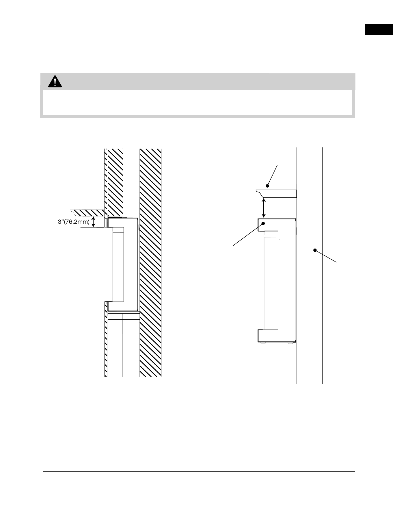
• When using paint or lacquer to finish the mantel, the paint or lacquer must be heat resistant to
prevent discolouration.
2.2 minimum mantel clearances
TOP OF
APPLIANCE
WALL
A
PPLIANCE
4”(100mm)
WARNING
3”(76.2mm)
EN
installation
14 | W415-10008161 | A-0
Wall
Wall
Wall
x6
2.3 wall mount installation
Due to the many different materials used on different
walls, it is highly recommended that you consult your
local builder before installing this appliance on the wall.
1. Select a location that is not prone to moisture and
is located at least 91.4 cm away from combustible
materials, such as curtains, drapes, furniture,
bedding, paper, etc.
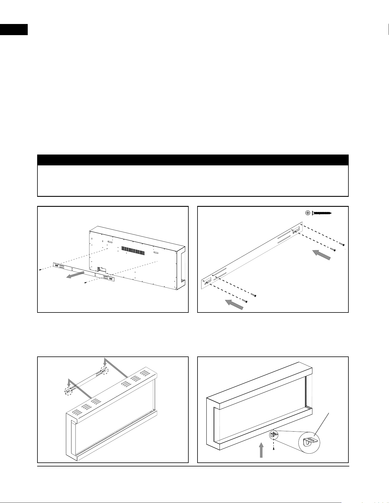
2. Have two people hold the appliance against the
wall to determine its final location.
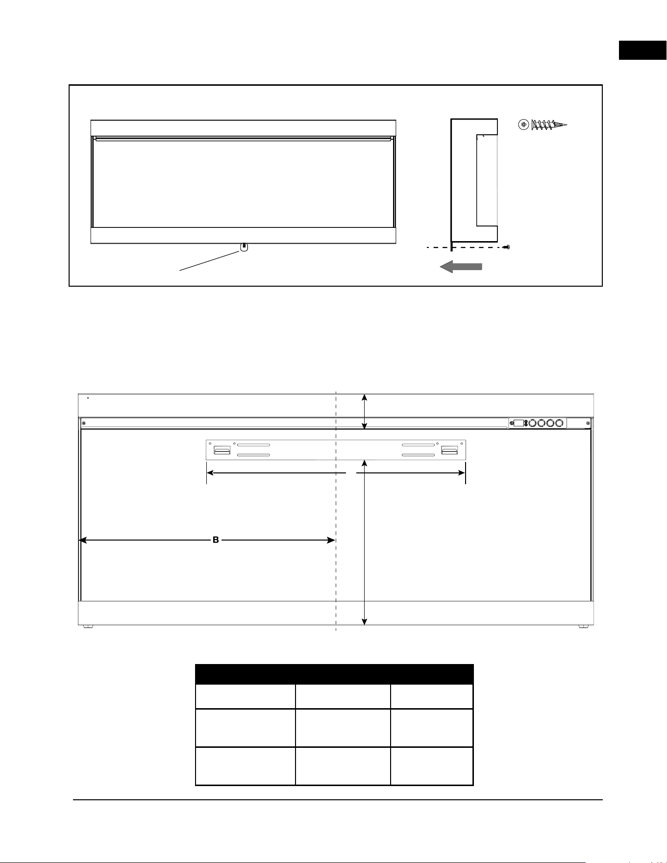
3. Place the appliance face down on a soft, non-
abrasive surface. Remove the bracket from the
back of the appliance by removing the screws
(Fig. 1). Set the bracket aside and discard
the screws
4. Mark out the location, then mount the bracket
onto the wall using screws (supplied). This bracket
MUST have the hooks facing upward and it MUST
be level (Fig. 2).
Fig. 1
Fig. 3
Fig. 2
Fig. 4
MDF
Bracket
It is strongly recommended that the mounting bracket be screwed into the wall studs where possible. If the
wall studs cannot be used, ensure that the supplied plastic anchors are used to affix the bracket to the wall
and that the bracket is adequately secured.
note:
5. With the wall-mounting bracket installed, have two
people lift the appliance up and insert the hooks
on the bracket into the slots on the back of the
appliance (Fig. 3).
6. Install the MDF bracket (supplied) to the bottom of
the appliance by removing the unpainted existing
screw in the centre of the appliance and then
reinstalling it with the MDF bracket (Fig. 4).
EN
installation
A-0 | W415-10008161 | 15
x1
FRONT VIEW SIDE VIEW
MDF Bracket
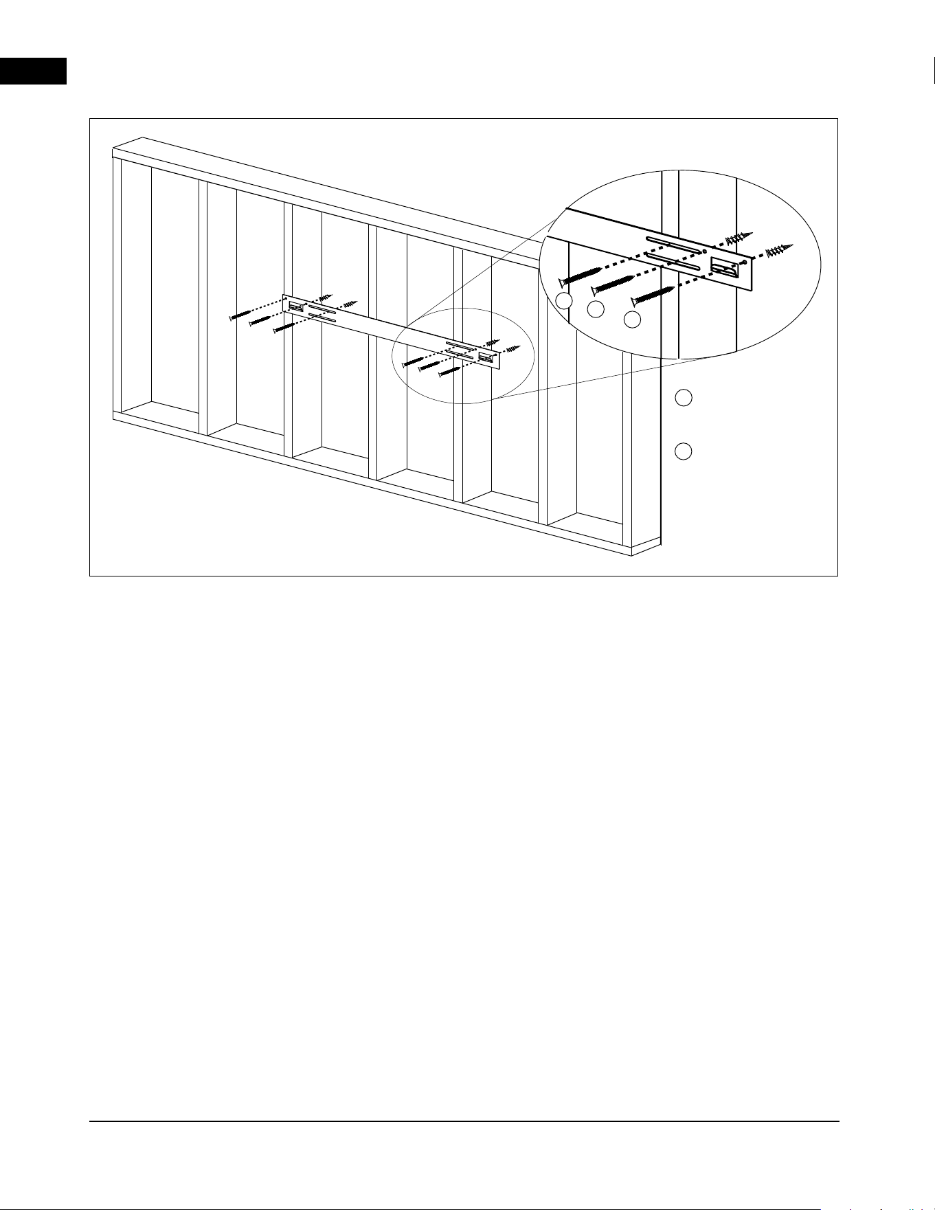
7. With the MDF bracket secured to the appliance,
secure the MDF bracket to the wall using one
screw (Fig. 5).
8. Check the appliance for stability, ensuring that the
bracket will not pull free from the wall (Fig. 6).
9. Install media (see “media installation” section).
You must complete this step before moving
onto the next step.
10. Install the front glass (see “front glass installation/
removal” section).
Model A B
NEFL50AB-AU
640 mm 635 mm
NEFL62AB-AU
640 mm 788 mm
NEFL74AB-AU
1071 mm 940 mm
A
Centre
16 1/8”
(410mm)
4 9/16” (116mm)
Fig. 5
EN
installation
16 | W415-10008161 | A-0
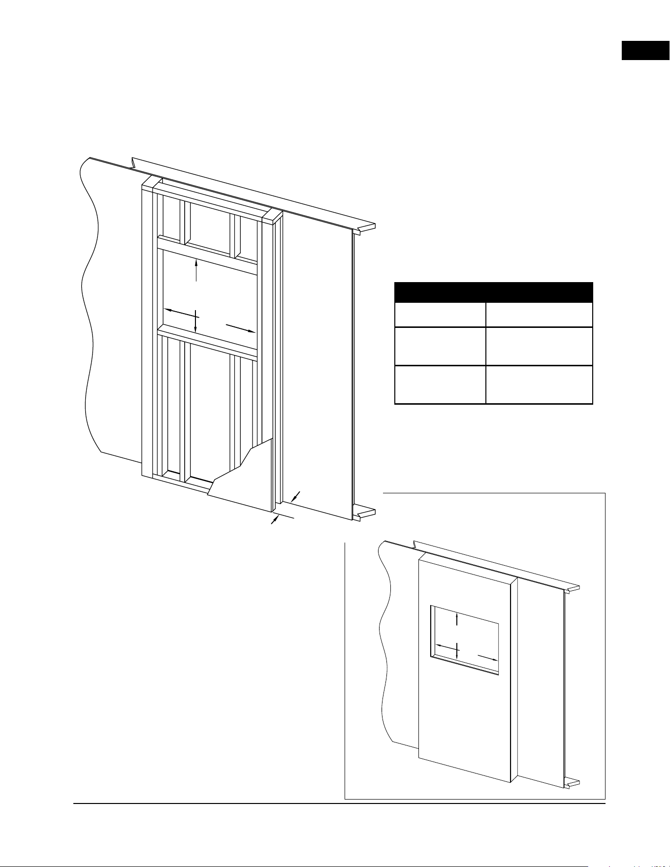
For illustrative purposes only.
Exact stud location may vary based on installation location.
Where studs are
present, use screws.
Where studs are
NOT present, use
drywall anchors
and screws.
B
A
A
B
B
Fig. 6
EN
installation
A-0 | W415-10008161 | 17
A
A
23 7/16"
(595 mm)
3.5"
(88.9 mm)
23 7/16"
(595 mm)
Finishing
Material
Finishing Material
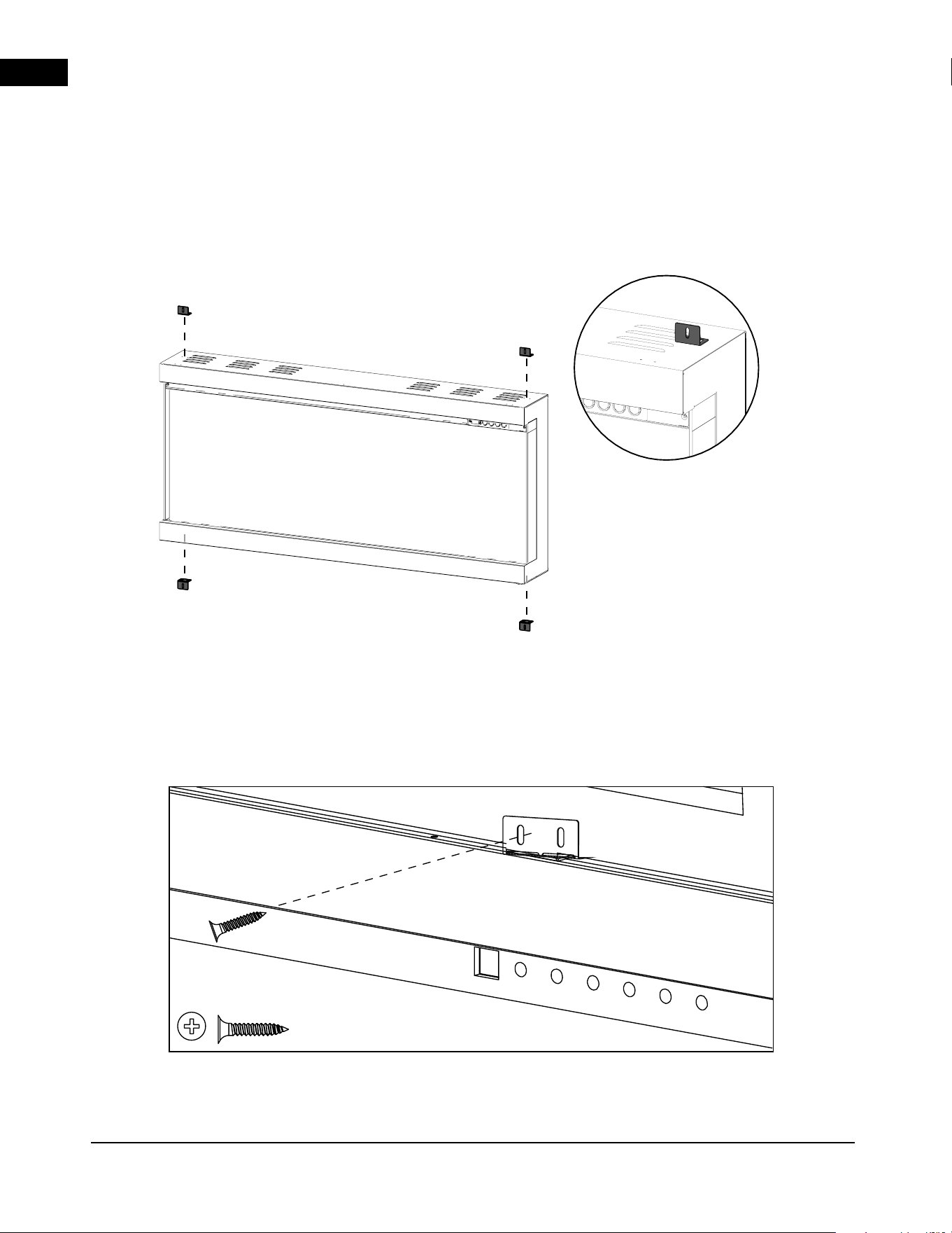
2.4 partial recessed installation
2.4.1 rough framing
A
A
23 7/16"
(595 mm)
3.5"
(88.9 mm)
23 7/16"
(595 mm)
Finishing
Material
(Non-Load Bearing)
(partially recessed)
Model A
NEFL50AB-AU
1283 mm
NEFL62AB-AU
1588 mm
NEFL74AB-AU
1892 mm
EN
installation
18 | W415-10008161 | A-0
2.4.2 unit preparation
1. Ensure front glass is removed from appliance
before installation prep (see front glass removal).
2. Place the appliance face UP on a soft,
non-abrasive surface.
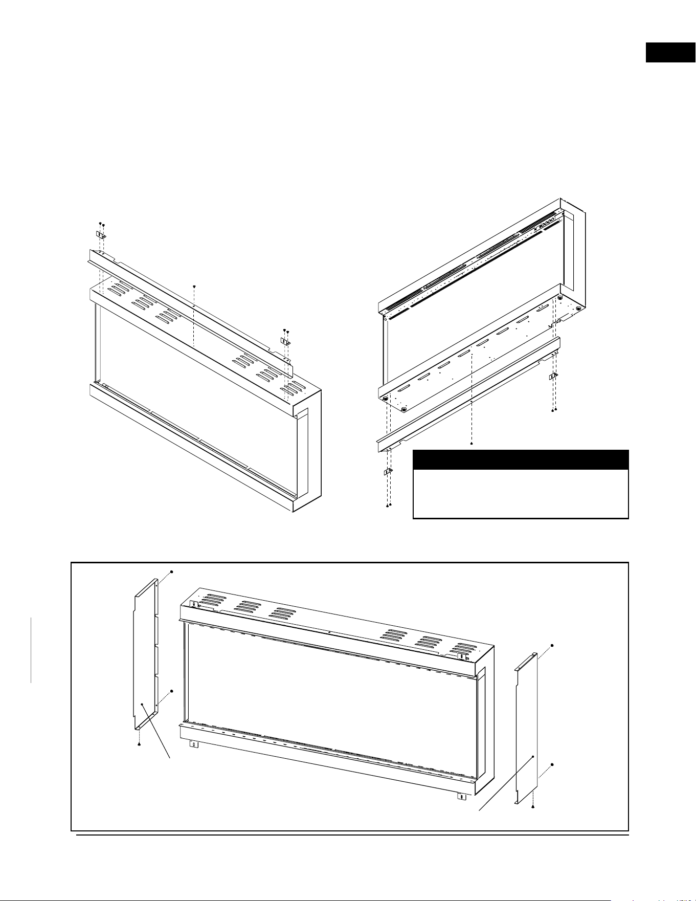
3. Install the metal brackets to the rearmost set of
holes on the top of the fireplace using the screws
and washers (supplied).
4. Remove the power cord and complete hard-wiring
(see “hard-wiring installation” section).
5. Insert the appliance into the rough framing by
securing the screws (supplied) through the slotted
holes on each securing bracket of the appliance
into the rough framing. (Fig. 7).
6. Proceed to Finishing
Fig. 7
EN
installation
A-0 | W415-10008161 | 19
Side Panel
Side Panel
2.5 built in application
2.5.1 trim / panel installation
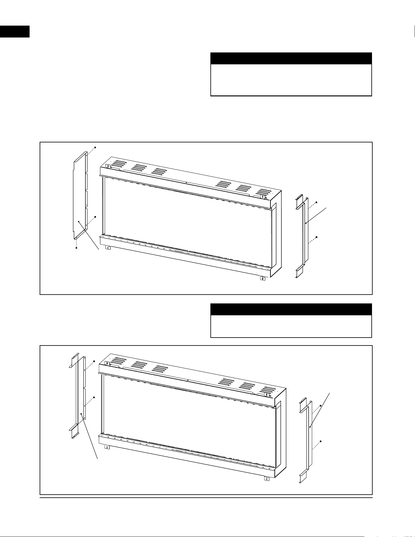
The Fireplace requires the use of additional trim and panels in order to be recessed fully into the wall to allow
a protective surface and butting edge for finishing material. Install the top and bottom trims with the mounting
brackets using the screws provided as shown. Review the installation options for single, 2 sided and 3 sided
applications and proceed with next steps for side trim and/or panel installation.
1. Remove the screws from the back and bottom of the fireplace which align with the panel then secure the
panels using the metal screws provided (Fig. 8).
When installed fully recessed into the wall
with both left and right sides covered, the
appliance will have a front view only.
note:
Fig. 8
EN
installation
20 | W415-10008161 | A-0
note:
note:
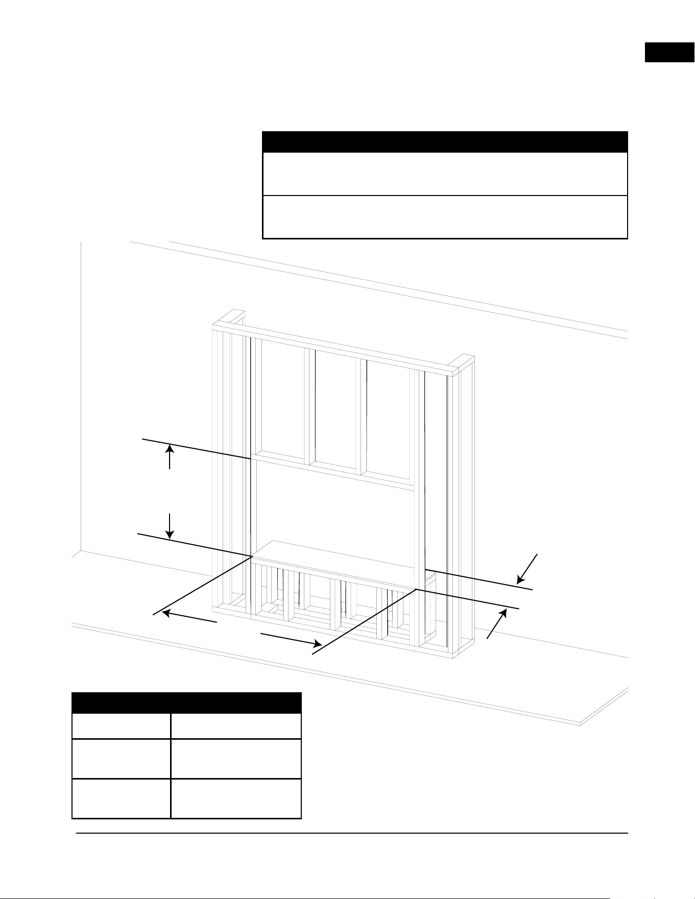
For an end wall enclosure with 2 sides (front and 1 side)
install the top and bottom trims along with 1 C shaped
panel and 1 flat panel to the respected side which are
required to be open and closed.
When installed fully recessed into the wall with one
side open, the appliance will have a front view and left-
or right-sided view depending on desired open side.
When installed with both sides open, the appliance will
have a front view, as well as left- and right-sided views.
2. For desired open side, remove the screws from the back of the fireplace which align with the trim then secure
the trim using the metal screws provided (Fig. 9).
3. For desired closed side, remove the screws from the back and bottom of the fireplace which align with the
panel then secure the panels using the metal screws provided (Fig. 10).
4. Secure both side trims by removing the screws
from the back of the fireplace which align with
the trim then secure the trim using the metal
screws provided. (Fig. 10).
Side Panel
Side Trim
Side Trim
Side Trim
Fig. 9
Fig. 10
EN
installation
A-0 | W415-10008161 | 21
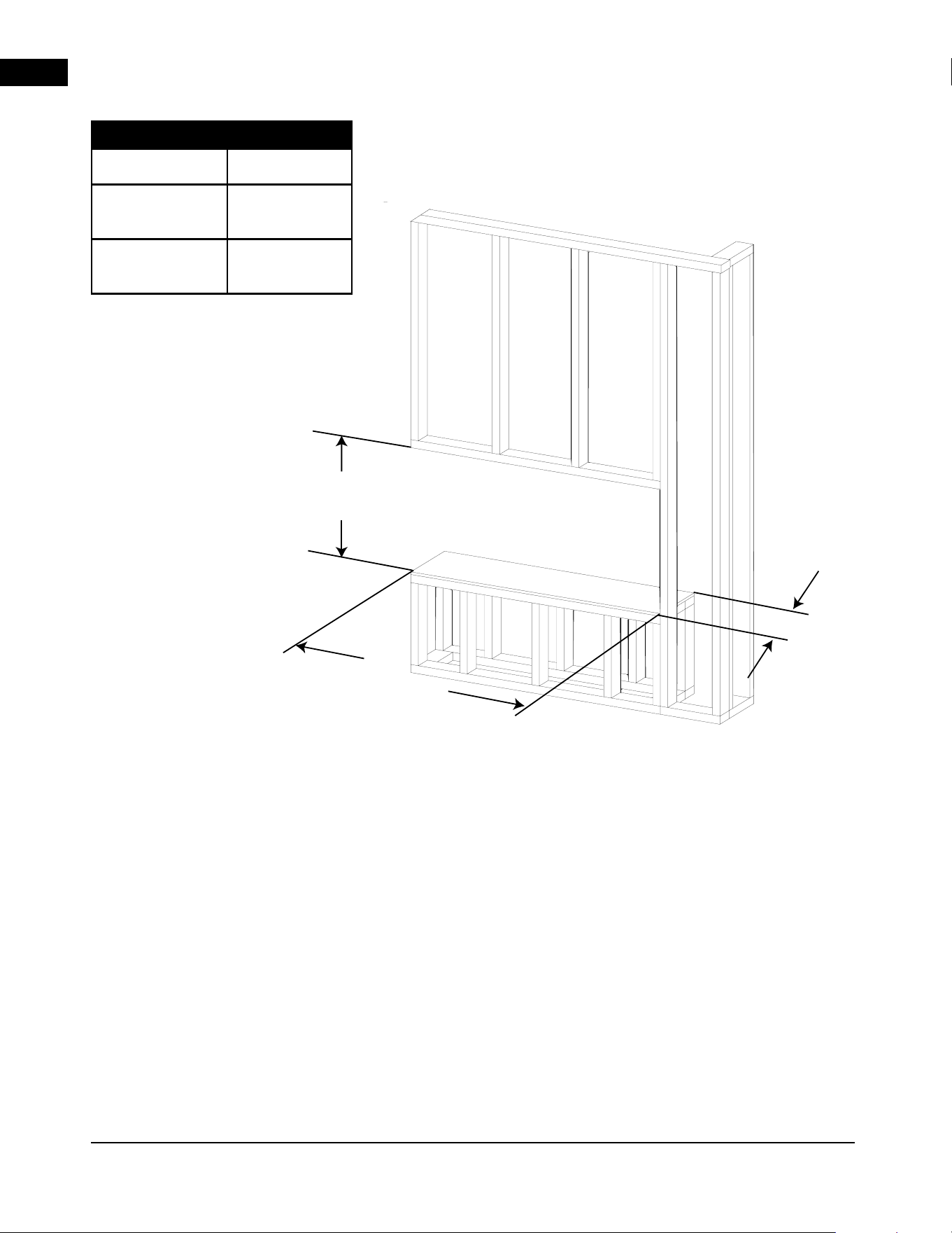
2.5.2 rough framing
Non-Load Bearing Wall Framing
Hard wire location
Appliance is NOT load-bearing. Carefully consider weight of finishing
materials when constructing rough framing.
Ensure installation complies with all local building codes and
requirements.
note:
23 7/16"
(595mm)
7-1/2”
A
Model A
NEFL50AB-AU
1283 mm
NEFL62AB-AU
1588 mm
NEFL74AB-AU
1892 mm
EN
installation
22 | W415-10008161 | A-0
2.5.3 recessed installation
1. With the brackets and trim installed, have 2 people
lift the appliance up and insert the appliance into
the rough in framing.
2. Check the appliance for stability and then secure
it into the rough framing by fastening the supplied
wood screws through the slotted holes on each
securing bracket.
23 7/16"
(595mm)
7-1/2”
A
Model A
NEFL50AB-AU
1283 mm
NEFL62AB-AU
1588 mm
NEFL74AB-AU
1892 mm
EN
electrical information
A-0 | W415-10008161 | 23
3.0 electrical information
It is necessary to hard-wire this appliance when
recessed into the wall. A qualified electrician must wire
the appliance directly to the household wiring.
This appliance must be electrically wired and grounded
in accordance with local codes.
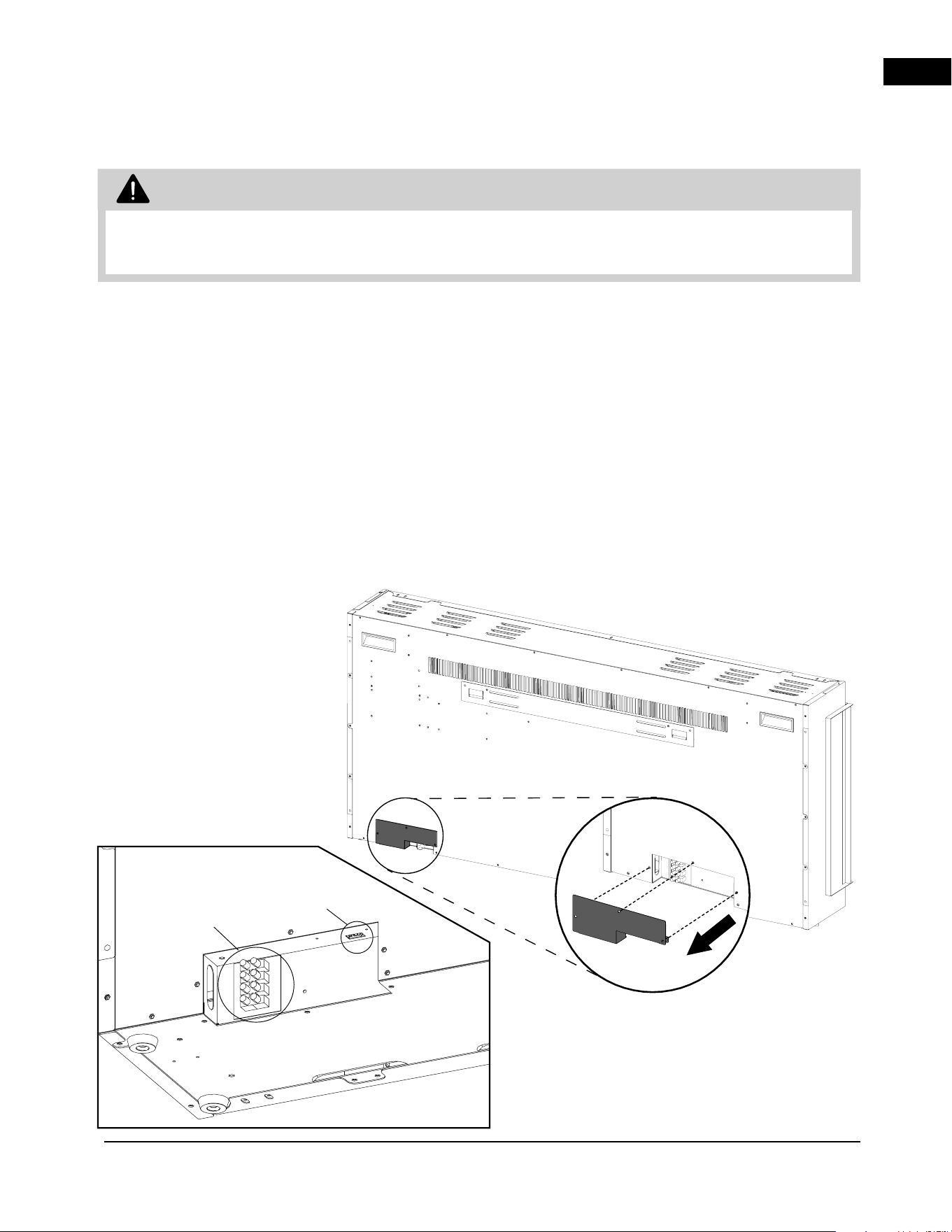
Before hard-wiring the appliance, remove the junction
box control cover by removing the fasteners as shown.
1. Remove the power cord by ensuring the appliance
is unplugged then locate and remove the screws
connecting the cover plate to the fireplace. Once
removed, Loosen the terminal screws too pull the
wires out of the terminal block.
2. Locate the desired 2 conductor or 3 conductor
wire cable to the bottom right side of the
enclosure for the hard-wiring installation based on
the desired 240V AC 50 Hz heat output capability.
3. With the appliance in the rough-in framing, insert
far enough into the enclosure to locate the supply
wires to the terminal block.
4. Insert the wires from your home through the junction
box cover plate with the strain relief (supplied) and
locate the wires to the specified terminal block
location based on desired voltage selection.
Optional
Wall mount
Controller
Hardwire
Connection
• Turn off the appliance completely and let cool before servicing. Only a qualified service person should
service and repair this electric appliance.
WARNING
EN
electrical information
24 | W415-10008161 | A-0
3.2 optional wall-mount controller installation
The wall-mount controller is designed with a recessed
securing bracket to allow it to secure directly to the
finishing material and does not require to be fixed to
a stud. Route the wire harness for the wall-mount
controller from the fireplace junction box to the desired
location for the wall-mount controller. Some finishing
material may need to be fixed to the enclosure to
allow the wall-mount controller to be secured. See
finishing material installation.
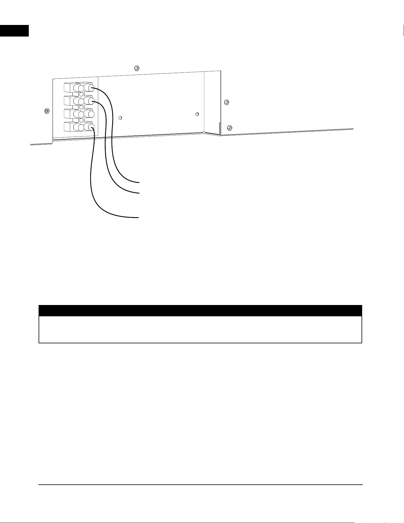
3.1 240 V hard-wiring
1. Insert Green or bare copper wire to the designated G Terminal. Tighten the screw.
2. Insert Neutral wire to the designated N Terminal. Tighten the screw.
3. Insert L1 wire to the designated L1 Terminal. Tighten the screw.
4. Make sure all connections are tightened properly.
5. Reinstall the junction box cover plate.
If installing with Optional Wall mount Controller installation. Plug in the wire harness connection to the
4 pin connector located above the hard wire terminal block.
note:
240 V
G
N
L1
G
N
L
EN
electrical information
A-0 | W415-10008161 | 25
4.0 finishing
4.1 finishing materials
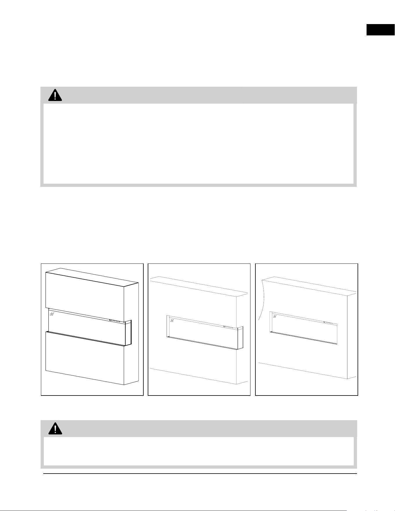
1. Both Combustible and non-combustible finishing
materials can be used for this product installation.
2. Finishing material will be covering the front of the
unit and will butt against the finishing material edge
flange (Fig 11).
• Risk of fire!
• Never obstruct the front opening of the
appliance.
• Do not strike, slam, or scratch. Do not operate
appliance with glass removed or cracked.
• Facing and/or finishing material must never
overhang into the appliance opening.
• Do not finish past the finishing edge trim.
Installing finishing materials past the finishing
edge trim will result in not being able to install
and/or open and close the front glass panel.
• Drywall dust may penetrate into the blower
bearings, causing irreparable damage. Care
must be taken to prevent drywall dust from
coming into contact with the blower or its
compartment. Any damage resulting from this
condition is not covered by the warranty policy.
WARNING
For illustrative purposes only
For illustrative purposes only
• Power supply service must be completed prior
to finishing to avoid reconstruction.
• Heat vents and air openings cannot be covered
in any circumstances.
WARNING
Two-Sided Viewing
Installation
For illustrative purposes only
Fig. 11
Three-Sided Viewing
Installation
Single-Sided Viewing
Installation
EN
finishing
26 | W415-10008161 | A-0
4.2 media installation
The front glass must be removed and the appliance
must be secured in its final location before the crystal
embers are installed (see “front glass installation and
removal” section).
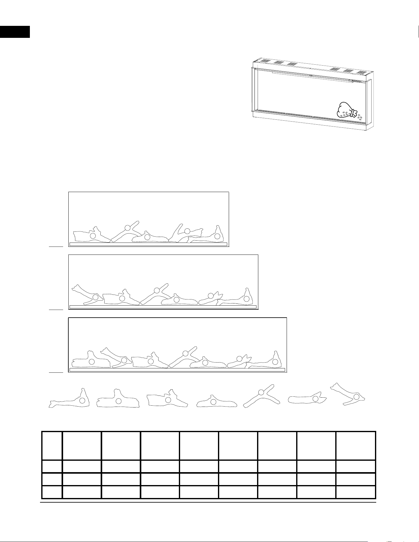
4.2.1 beach fire logs and woodland media kit
1. Start by laying out the 2 types of glass along the
media bed. Mix the 2 colors together to create
a realistic burning appearance once fireplace is
turned on.
2. Place the logs into desired position, reference
pictures are shown in figure 7 as recommended
location however can be changed based on
desired layout.
3. Place the mineral rocks and charcoal pieces
around the logs according to your desired
preference.
Fig. 12
1
3
5
2
6
4
7
1
3
5
6
4
7
1
3
5
7
4
1
3
5
2
6
4
7
50”
62”
74”
W135-10000191 W135-10000196 W135-10000197 W135-10000198W135-10000192 W135-10000193 W135-10000194
Size
W135-
10000191
#1
W135-
10000192
#2
W135-
10000193
#3
W135-
10000194
#4
W135-
10000196
#5
W135-
10000197
#6
W135-
10000198
#7
Total Qty.
50”
1 0 1 1 1 0 1 5
62”
1 0 1 1 1 1 1 6
74”
1 1 1 1 1 1 1 7
EN
finishing
A-0 | W415-10008161 | 27
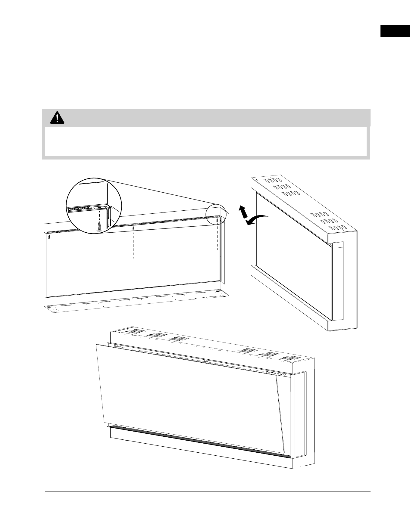
4.3 front glass installation and removal
Remove the screws holding the securing brackets at
the top of the glass. Pull the glass away from the unit
then lift up and out. Once removed, the glass should
be placed on a soft non-abrasive surface.
• Before the front glass is installed or removed, unplug the appliance and wait until appliance is cool to
the touch. Glass can be heavy and fragile, so handle with care.
WARNING
EN
finishing
28 | W415-10008161 | A-0
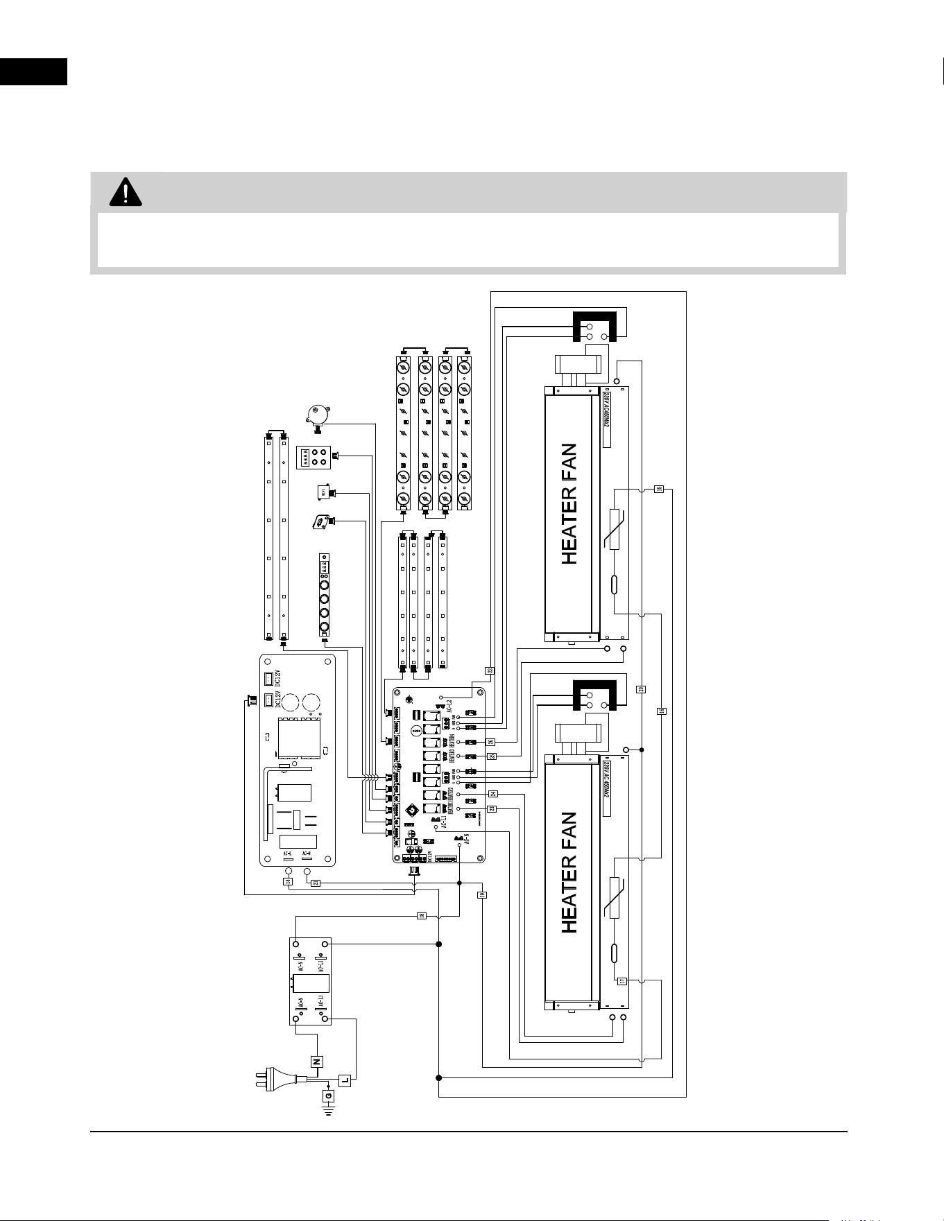
5.0 wiring diagram
5.1 NEFL50AB-AU wiring diagram
• Turn off the appliance completely and let cool before servicing. Only a qualified service person should
service and repair this electric appliance.
WARNING
NEFL50AB-AU
EN
wiring diagram
A-0 | W415-10008161 | 29
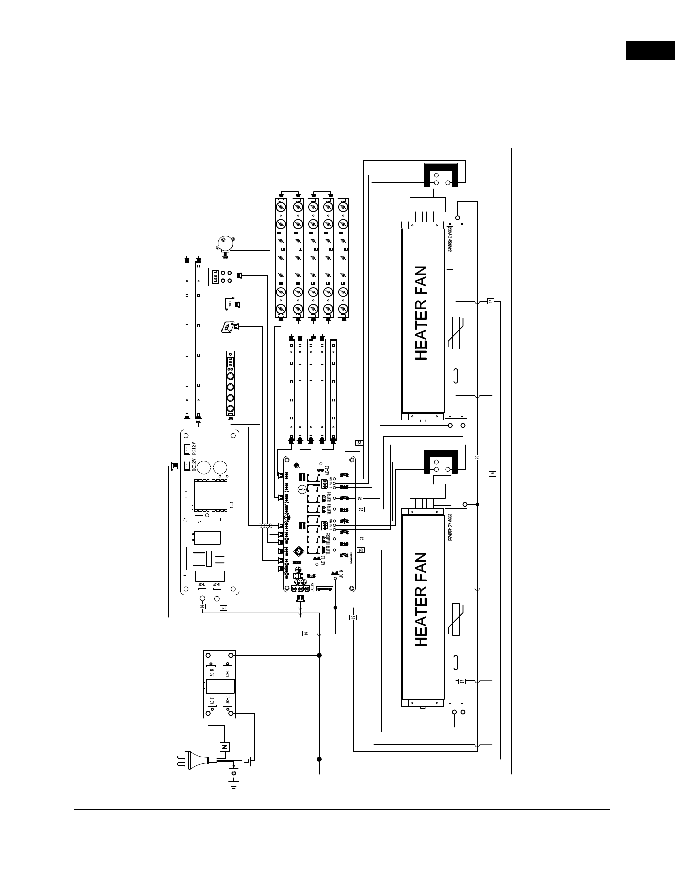
5.2 NEFL62AB-AU wiring diagram
NEFL62AB-AU
EN
wiring diagram
30 | W415-10008161 | A-0
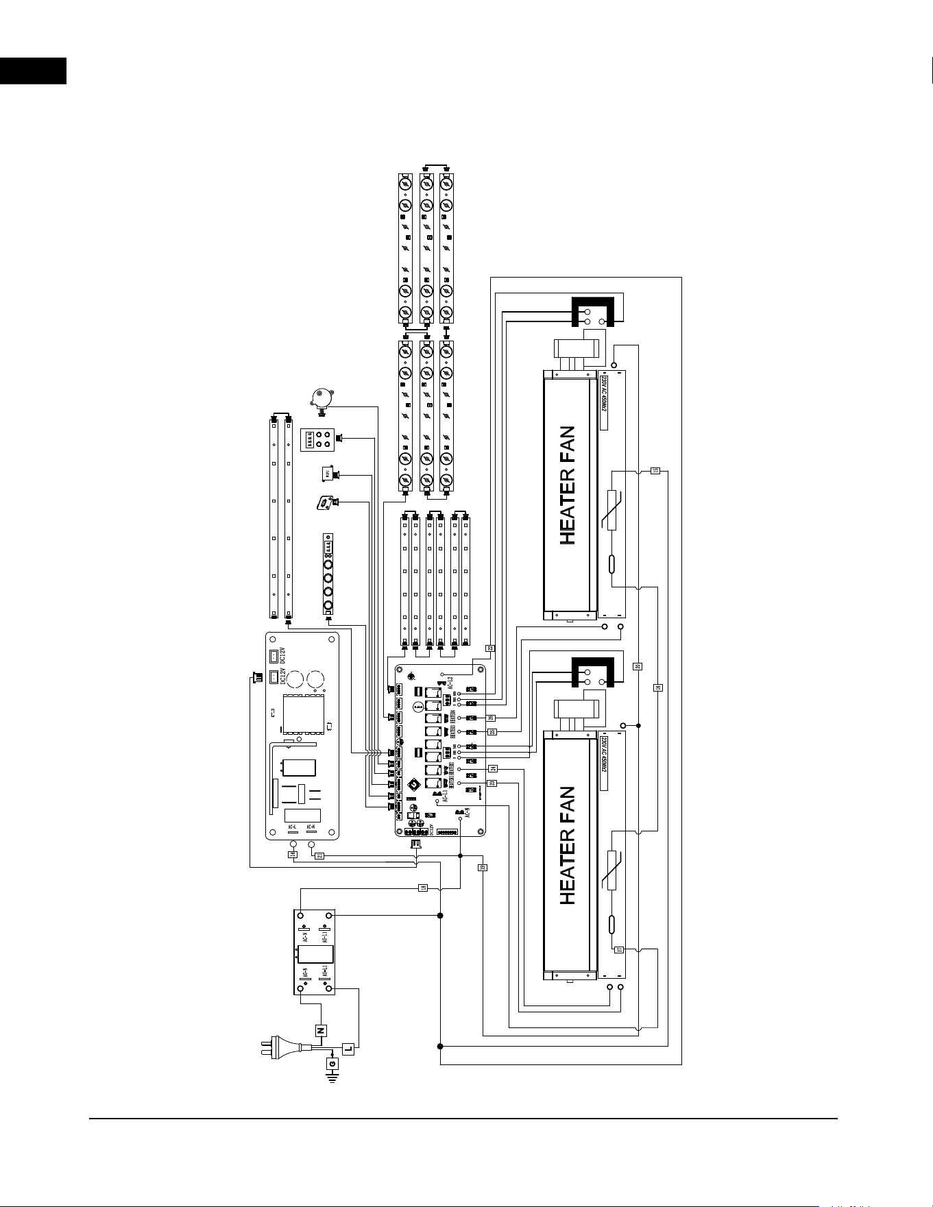
5.3 NEFL74AB-AU wiring diagram
NEFL74AB-AU
EN
operation
A-0 | W415-10008161 | 31
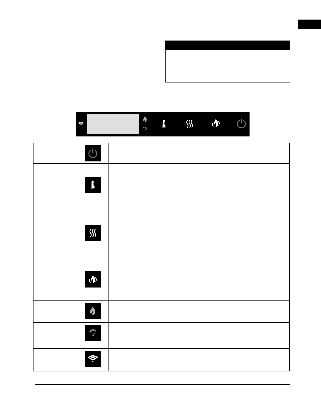
Power
Turn the appliance on/off.
Temperature
Control the temperature of the appliance with 11 settings.
Settings:
18 ºC, 19 ºC, 20 °C, 21 ºC, 22 ºC, 23 ºC, 24 ºC, 25 ºC, 26 ºC, 27 ºC and OFF.
Note: Press and hold the button for 3s to switch between °C and °F
Heater
Turns the heater and blower on/off.
Settings:
H-0: Heater and blower off
FAN: Heater is off and blower is on
H-1: Heater and blower on
Note:
Heater control function can be enabled/disabled by holding the button for 3s. When
the heater function is disabled, “LOC” will be displayed.
Flame
Turn the flame effect on/off.
Settings:
F-1: Both orange and yellow flame on, 100% brightness
F-0: Both orange and yellow flame off
Note:
Press and hold the button 8s for Wi-Fi setup.
ECO Mode
Indicator
Indicates the appliance is working under ECO mode.
Boost Mode
Indicator
Indicate the appliance is working under Boost mode.
Wi-Fi
Indicator
Indicates the appliance is connected to the wireless network.
Once the appliance has been electrically connected
to a grounded circuit and the breaker is on, it is
ready to operate.
6.1 operating control panel
The control panel is located on the top right-hand corner
of the appliance.
note:
Ensure the house circuit breakers for the power
supply are turned on. In the event of a power failure,
the appliance will lose its memory function and will
reset to factory mode when the power returns.
6.0 operation
EN
operation
32 | W415-10008161 | A-0
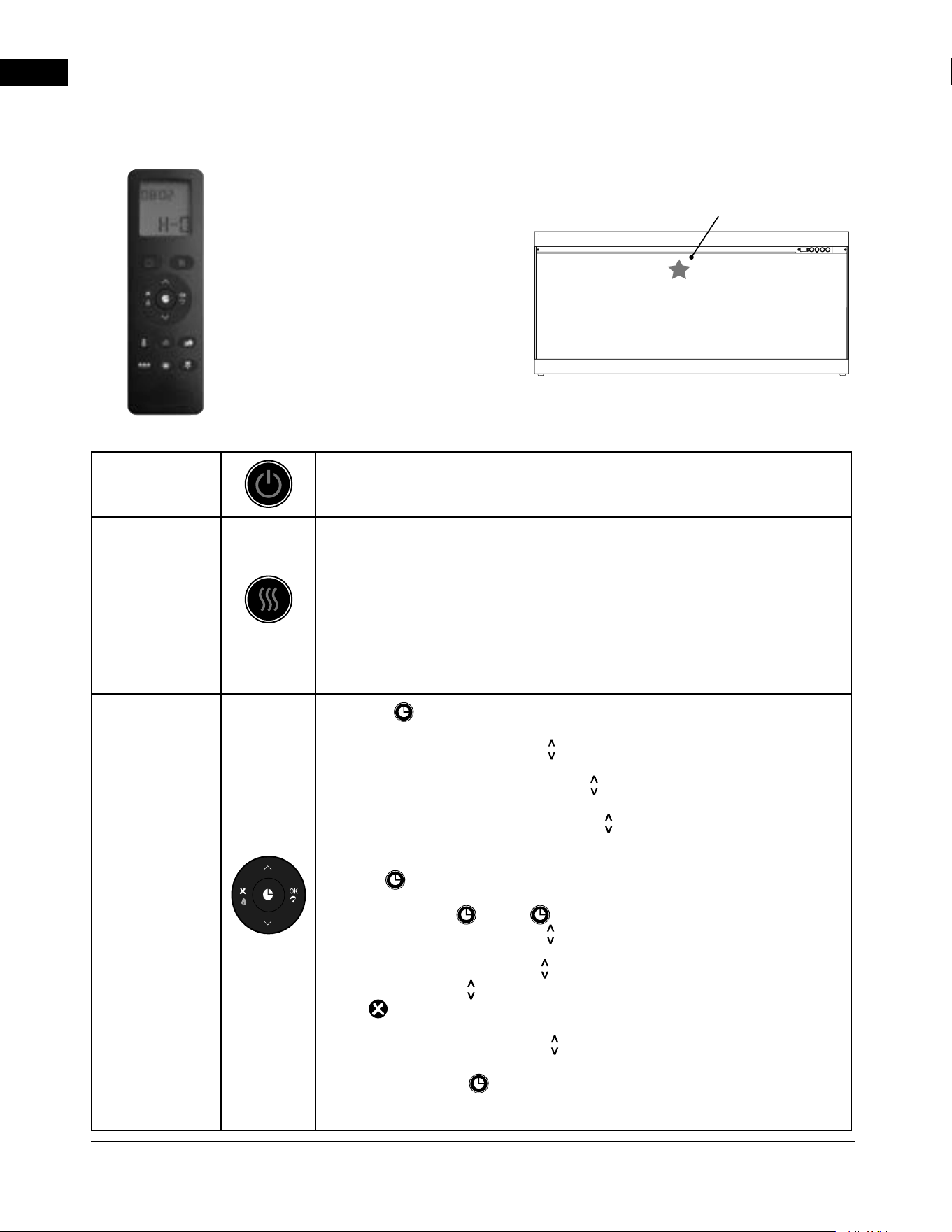
Features:
Power / standby
Heater setting: H-0, FAN, H-1
ECO mode
Boost mode
Temperature setting
Flame color setting: orange/yellow
Flame speed setting
Ember bed color setting
Ember bed brightness setting
Top light setting
Special features:
7/24 timer programming
open window alert
Power/
Standby
Turn the appliance on/off.
Heater
Turns the heater and blower on/off.
Settings:
H-0: Heater and blower off
FAN: Heater is off and blower is on
H-1: Heater and blower on
Note:
Heater control function can be enabled/disabled by holding the button for 3s. When
the heater function is disabled, “LOC” will be displayed.
7/24 Timer
Press the button to set the current day and time.
When “MON” starts flashing, use to select current day.
Press OK to complete setting.
When the hour digits start flashing, use to select the current hour.
Press OK to complete the setting.
When the minute digits start flashing, use to select the current minute.
Press OK to complete the setting.
Hold the button to set the weekly schedule.
Press and hold the for 3s. ON logo will appear on screen.
When “MON” starts to flash, use to select the desired day.
Press OK to complete setting.
When “--:--” starts flashing, use to select the time. Press OK to confirm.
Every time when the is pressed, 30 minutes will be added or reduced.
Press any time to clear digits. Leave hour and minute in “--:--” to not
set up the schedule.
When “18 ºC” starts flashing, use to select desired temperature to on
heater (thermostat function on). Press OK to complete the setting.
After finishing step 4, OFF logo will appear on screen. Repeat steps 2 and
3 to set the day and time for off schedule.
Repeat steps 1 to 5 to set the time ON/OFF schedule every day.
6.2 operating remote control
Infrared Remote
Point Remote Here
EN
operation
A-0 | W415-10008161 | 33
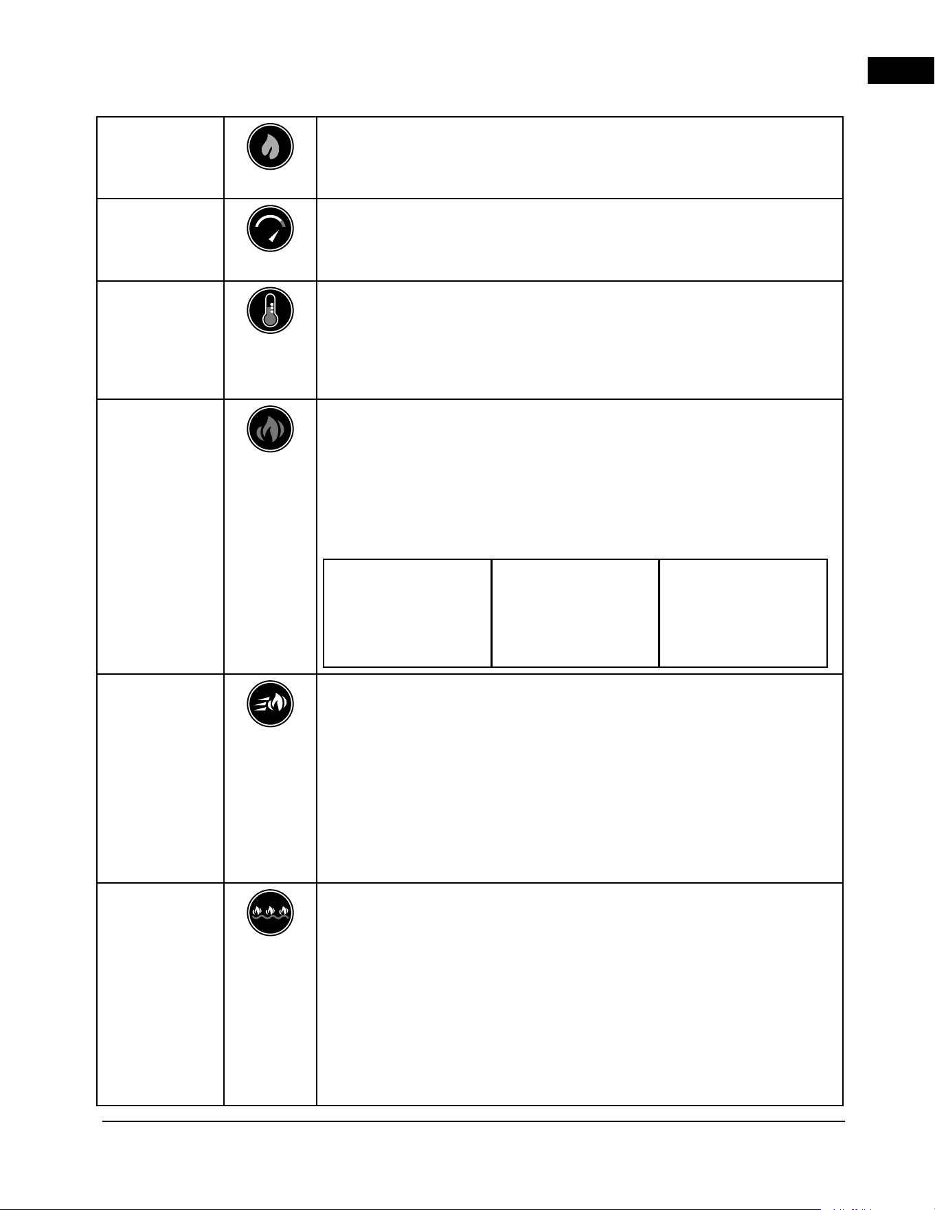
ECO
Hold the button for 3s to turn on/off heater with half heat output (ECO mode).
Note:
When running in ECO mode, ECO indicator will light up on the control panel.
Boost
Hold the button for 3s to turn on/off Boost mode for 30 mins.
Note: When running in Boost mode, BST indicator will light up
on the control panel.
Thermostat
Control
Control the temperature of the appliance. Use to change settings.
Settings:
18 ºC, 19 ºC, 20 °C, 21 ºC, 22 ºC, 23 ºC, 24 ºC, 25 ºC 26 ºC, 27 ºC and OFF.
Note: Press and hold the button for 3s to switch between °C and °F.
Flame
Turn the flame effect on/off.
Press the button, flame 1 icon on the LCD display will start to flash.
Use the
< >
to change brightness.
Press the button again, flame 2 icon on the LCD display will start to flash.
Use the
< >
to change brightness.
Press the button for a third time, both flame 1 and flame 2 icons on the LCD
display will start to flash.
Icon 1: Orange flame.
OF4 (100%)
OF3 (75%)
OF2 (50%)
OF1 (25%)
OF0 (0%)
Icon 2: Yellow flame.
YF4 (100%)
YF3 (75%)
YF2 (50%)
YF1 (25%)
YF0 (0%)
Icon 1 + 2: Both flames.
F-1 Both flame on (100%)
F-0 Both flame off. (0%)
Flame Speed
Control the flame speed.
Press the button, flame speed icon will start to flash on LCD display.
Use
< >
to change settings.
Settings:
S-3 (12 RPM)
S-2 (10.5 RPM)
S-1 (9 RPM)
S-5 (15 RPM)
S-4 (13.5 RPM)
S-3 (12 RPM)
Ember Bed
Color
Control the ember bed color.
Press the button, ember bed color icon will start to flash on the LCD display.
Use
< >
to change settings.
Settings:
L01
L02
…
L13
L-C (Cycle)
L01
< >
EN
operation
34 | W415-10008161 | A-0
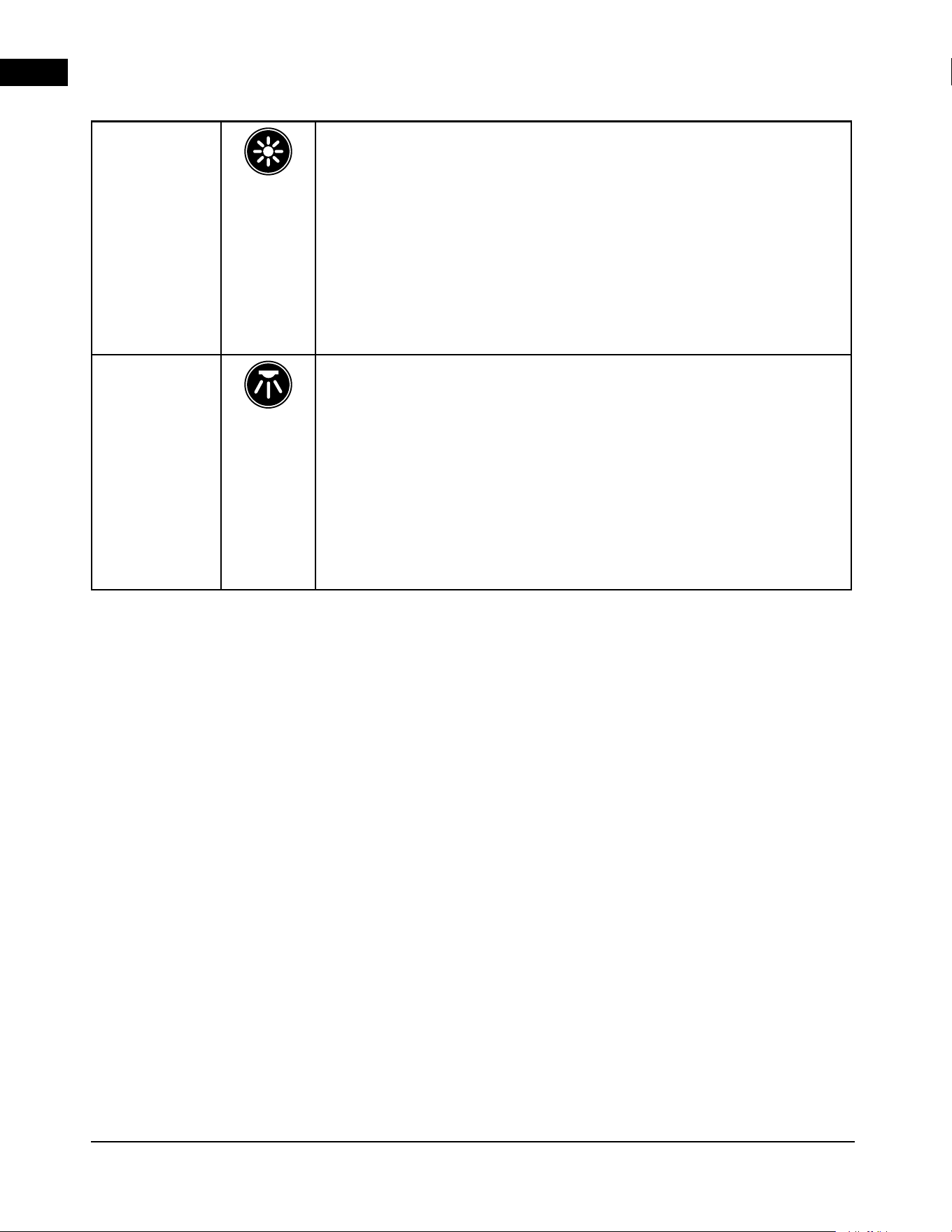
Ember Bed
Brightness
Control ember bed brightness.
Press the button, ember bed bright ness icon will start to flash on the LCD
display. Use
< >
to change settings.
Settings:
B-4 (100%)
B-3 (60%)
B-2 (40%)
B-1 (10%)
B-0
B-F (Fade in and fade out)
B-4
Top Light
Control the top light.
Press the button, top LED icon will start to flash on the LCD display.
Use
< >
to change settings.
Settings:
D01
D02
…
D13
D-C (Cycle)
D00
D01
EN
operation
A-0 | W415-10008161 | 35
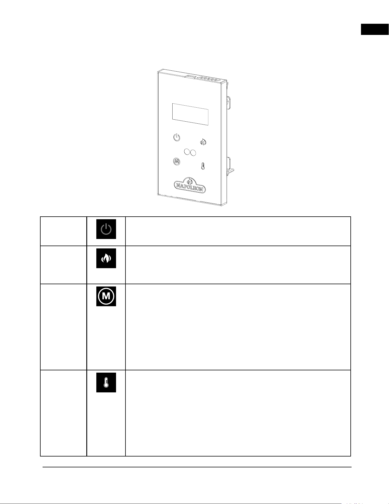
Power
Turn the appliance on/off.
Flame On/
Off
Turns the flame on/off.
Settings:
F-1: Flame on at 100% brightness for both orange and yellow flame (default setting)
F-0: Flame off
Mode
Selection
Switches between running modes.
Defualt setting: H-0
Settings:
H-0: Heater and blower off
FAN: Heater is off and blower is on
H-1: Heater and blower on
ECO: Heater running in economic mode
BST: Heater in enhance mode, blower running at high speed
Note: Heater control function can be enabled/disabled by holding the button for 3s. When
the heater function is disabled, “LOC” will be displayed.
Thermostat
Control
Press this button to activate the thermostat. Continue pressing the same button to
increase the temperature setting. Each press will increment the temperature
by 1 °C, starting from the default setting of 18 °C.
To turn off temperature mode:
Repeatedly press the button until no temperature value is displayed, indicating “OFF.”
The temperature setting will reset to the default value of 18 °C.
Settings:
18 ºC, 19 ºC, 20 °C, 21 ºC, 22 ºC, 23 ºC, 24 ºC, 25 ºC, 26 ºC, 27 ºC and OFF.
Note: Press and hold the button for 5s to switch between ºC and ºF.
6.3 operating optional wall mount controller
EN
napoleon connectivity
36 | W415-10008161 | A-0
7.0 napoleon connectivity
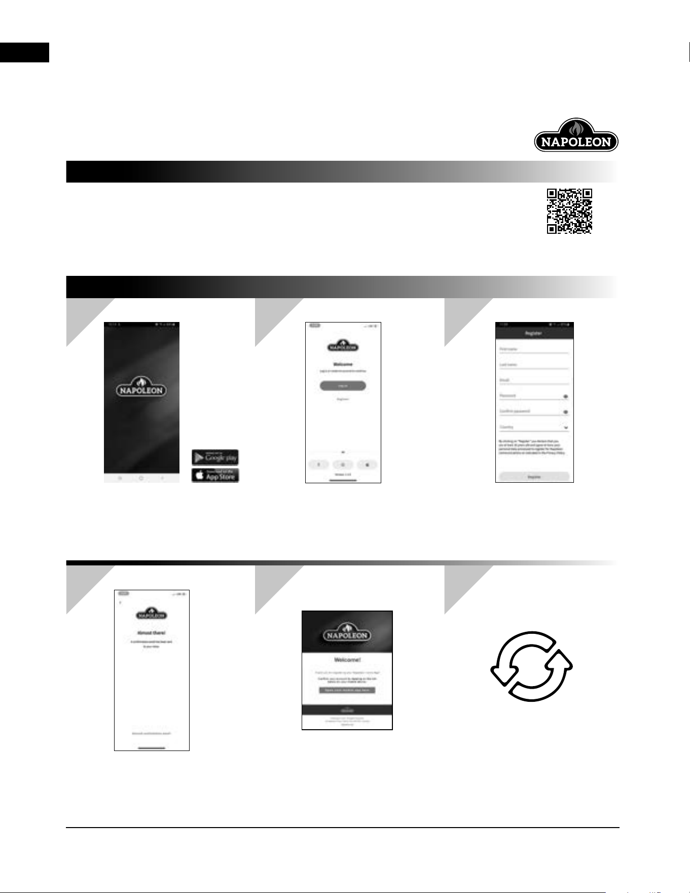
Access your appliance remotely by downloading
the Napoleon Home App from your app store.
In order to access the app, you will be required
to create an account by following the instructions
listed within the app (see below for details).
By pairing your appliance to the Napoleon
Home App via WiFi, you gain control to all
modes and functions of the appliance.
All notifications and alarms are sent through the
app to keep you connected with ease.
Download the Napoleon Home App
from your app store (Google Play or
Apple App Store).
Note: This requires Android 7.0
or iOS 13.0.
Register an account with the
Napoleon Home App OR sign-in
using your Facebook, Google, or
Apple account information.
Enter user information and create
a password for the account.
Select the country in which the
appliance is located.
The information entered in Step 3 will
be registered to the Napoleon Home
App and a confirmation will be sent to
the email provided.
Open email inbox and select the
confirmation link.
Note: The confirmation link must be
opened on the device that the
Napoleon Home App is installed on.
If no email is found, click “Re-Send
Confirmation Link” and check junk
folder.
NAPOLEON HOME APP
HOW DOES IT WORK?
Scan this QR code for
direct access to the
Napoleon Home App
website.
1
4
2
5
3
6
DOWNLOAD
ALMOST THERE
REGISTER
CONFIRM
CREATE
RE-CONFIRM
let’s get started
EN
napoleon connectivity
A-0 | W415-10008161 | 37
7.1 adding device
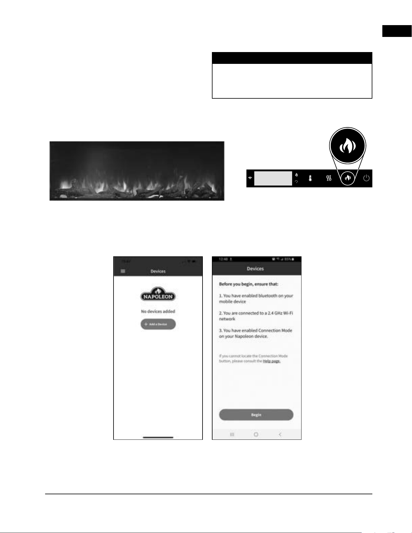
1. Ensure the appliance is plugged in and turned
on (Fig. 1).
2. Press and hold the FLAME Light Control button on
the appliance control panel for 10 seconds (Fig. 2).
3. The Fireplace will display P0 on the Display which will
indicate the fireplace is searching for a wifi connection.
Once connected the display will display P4 and the wifi
icon to the left of the display will be illuminated.
Fig. 1
Fig. 3 Fig. 4
Fig. 2
Depending on the manufacturing date of the product
the fireplace May also display a Blue light as a
secondary indication to the display showing P0.
note:
4. Select “Add Device” and accept permissions (Fig. 3 & 4).
EN
napoleon connectivity
38 | W415-10008161 | A-0
Fig. 5 Fig. 6
Fig. 7 Fig. 8 Fig. 9
Astound-40fa
Napoleon Guest
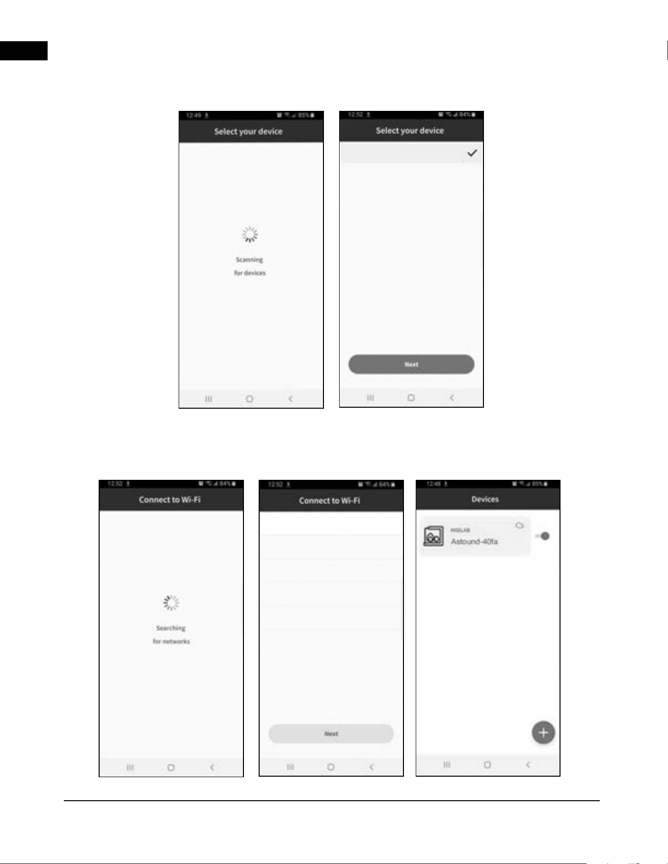
5. Search for devices and select the device from the list (Fig. 5 & 6).
6. Select desired Wi-Fi and connect by entering the
Wi-F password of your home (Fig. 7 & 8).
7. Once the appliance has been connected to the
access point, it can be given a nickname in order
to be more recognizable (Fig. 9).
EN
napoleon connectivity
A-0 | W415-10008161 | 39
7.2 using the app
7.2.1 power setting
7.2.2 heat setting
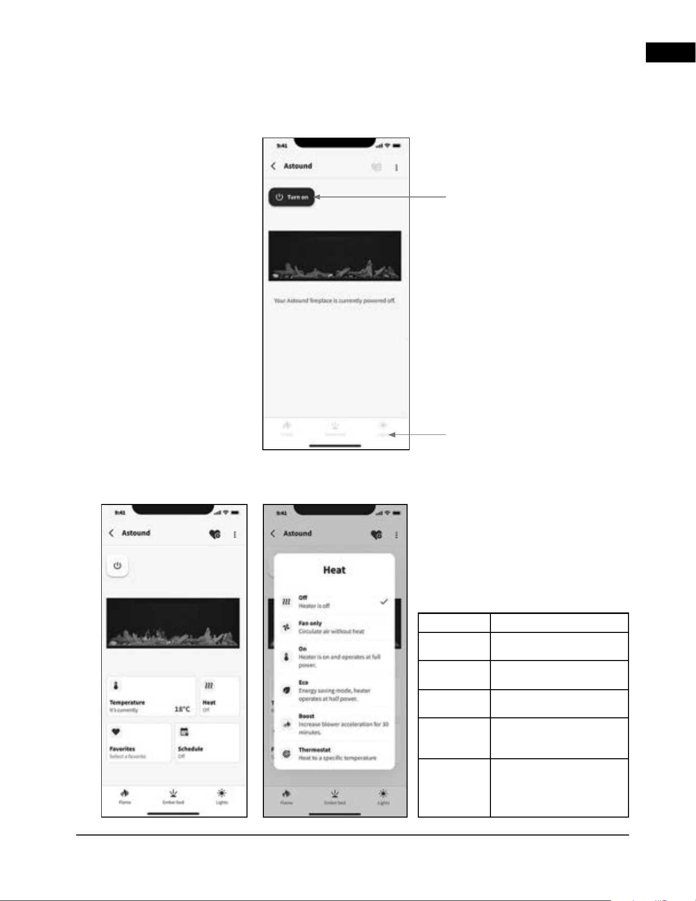
Power Setting:
Press to turn the
appliance On and Off.
Off
No heat.
Fan Only
Turns on only the fan to circulate
air without heat.
On
Heater is on and operates at full
power.
ECO
Energy saving mode, heater
operates at half power.
Boost
Increase blower acceleration for
30 minutes with Heater operates
at full power.
Thermostat
Automatically turns the heater
ON and OFF to regulate the
room temperature to the desired
set temperature.
The brightness settings are not
accessible on this home page when
the appliance is turned off. When
the appliance is turned on, navigate
to the bottom tabs to change
fireplace display settings.
Heat Setting:
The heat setting can be selected through
the heat tab on the appliance home
page. The current ambient temperature
is displayed on the temperature tab and
updated to reflect the target temperature
when thermostat mode is selected.
EN
napoleon connectivity
40 | W415-10008161 | A-0
7.2.3 ember bed setting
7.2.4 flame setting
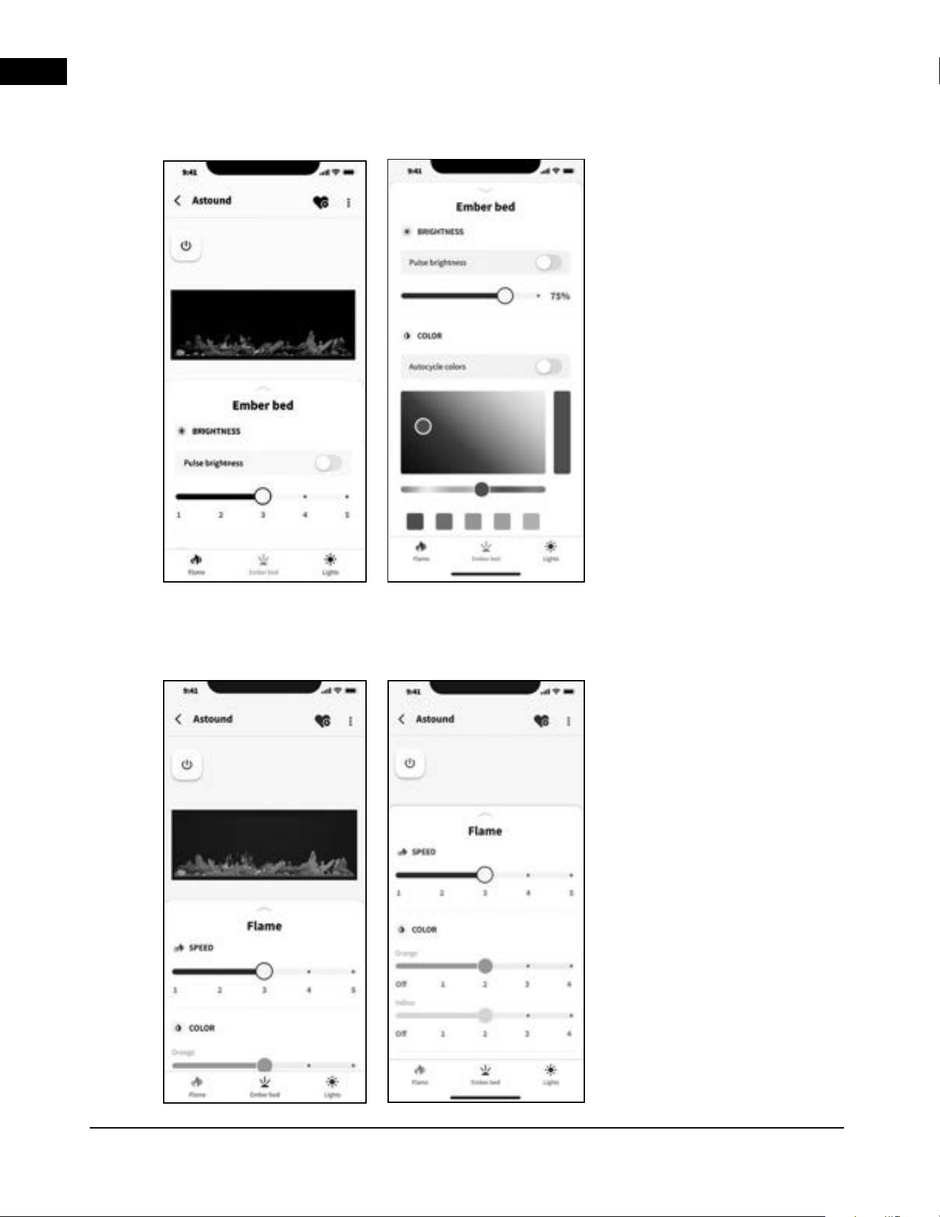
Ember Bed Setting:
Select the preferred ember bed
colours and brightness settings
from the list in the ember bed tab
or toggle the auto cycle or pulse
brightness function on to cycle
through all available colours.
Flame Setting:
Control the display of the different
flame colours by adjusting the
slider for each flame colour. The
flame speed can also be adjusted
on this page.
EN
napoleon connectivity
A-0 | W415-10008161 | 41
7.2.5 accessory lights settings
7.2.6 timer settings
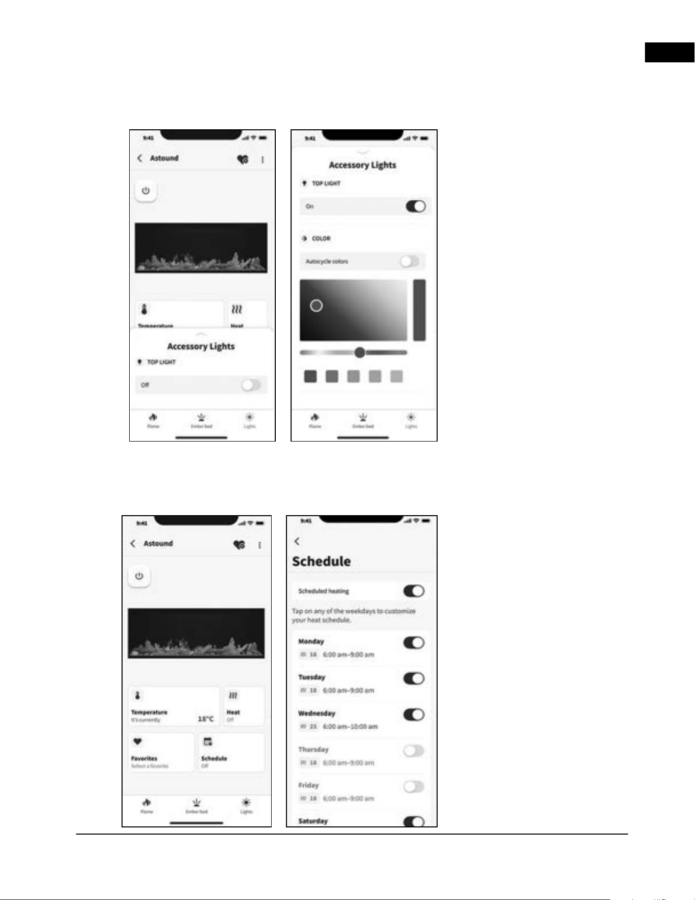
Accessory Lights Setting:
The weather display brightness can
be controlled in the app either on
the home page when the appliance
is turned off or the lights bottom
tab. The side light is also controlled
from the lights tab. Bulb warmth
selection and brightness can be
modified in this section.
Timer Settings:
The timer feature can be accessed
on the main page. Select from the
list of preset times to set a timer
that will power off the appliance
once the countdown is complete.
EN
maintenance
42 | W415-10008161 | A-0
8.0 maintenance
8.1 cleaning
Metal:
• Buff using a soft cloth, slightly dampened with a
citrus oil-based product.
• Do not use brass polish or household cleaners as
these products will damage the metal trim.
Glass:
• Use a good quality cleaner sprayed onto the cloth or towel.
Dry thoroughly with a paper towel or lint-free cloth.
• Never use abrasive cleaners, liquid sprays, or any
cleaner that could scratch the surface.
Vents:
• Use a vacuum or duster to remove dust and dirt
from the heater and vent areas.
Plastic:
• Wipe gently with a slightly damp cloth and a mild
solution of dish soap and warm water.
• Never use abrasive cleaners, liquid sprays, or any
cleaner that could scratch the surface.
Batteries must be disposed of according to the local laws and regulations. Some batteries may
be recycled, and may be accepted for disposal at your local recycling center. Check with your
municipality for recycling instructions.
• Always turn the heater off and unplug the power cord from the outlet before cleaning, performing
maintenance, or moving this appliance. Failure to do so could result in electric chock, fire, or personal injury.
• Never immerse in water or spray with water. Doing so could result in electric shock, fire, or personal injury.
WARNING
8.2 heater lockout switch
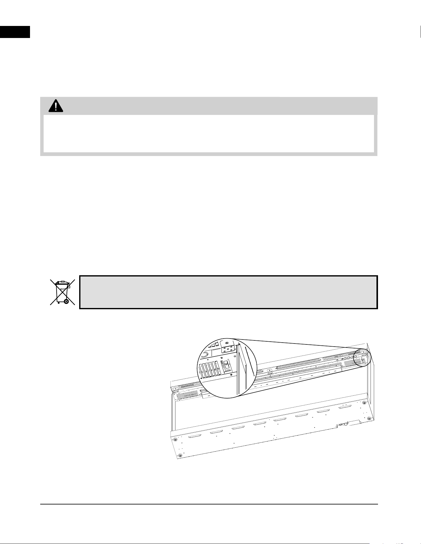
This fireplace features a switch positioned
behind the front glass, underneath the
touch panel, serving as an additional
mechanism to physically lock out the
heater’s operation. When activated the
display will flash LOC any time the heater
function is pressed and not allow the
heater to turn on.
EN
replacements
A-0 | W415-10008161 | 43
9.0 replacement parts
• Failure to position the parts in accordance with this manual or failure to use only parts specifically
approved with this appliance may result in property damage or personal injury.
Contact your dealer for questions concerning prices
and policies on replacement parts. Normally, all
parts can be ordered through your Authorized
dealer / distributor.
For warranty replacement parts, a photocopy
of the original invoice will be required to
honour the claim.
When ordering replacement parts always give the
following information:
• Model & Serial Number of appliance
• Installation date of appliance
• Part number
• Description of part
• Finish
Parts, part numbers, and availability are subject
to change without notice.
Parts identified as stocked will be delivered
within 2 to 5 business days for most delivery
destinations.
Parts not identified as stocked will be delivered
within a 2 to 4 week period, for most cases.
Parts identified as ‘SO’ are special order and can
take up to 90 days for delivery.
WARNING
EN
replacement parts
44 | W415-10008161 | A-0
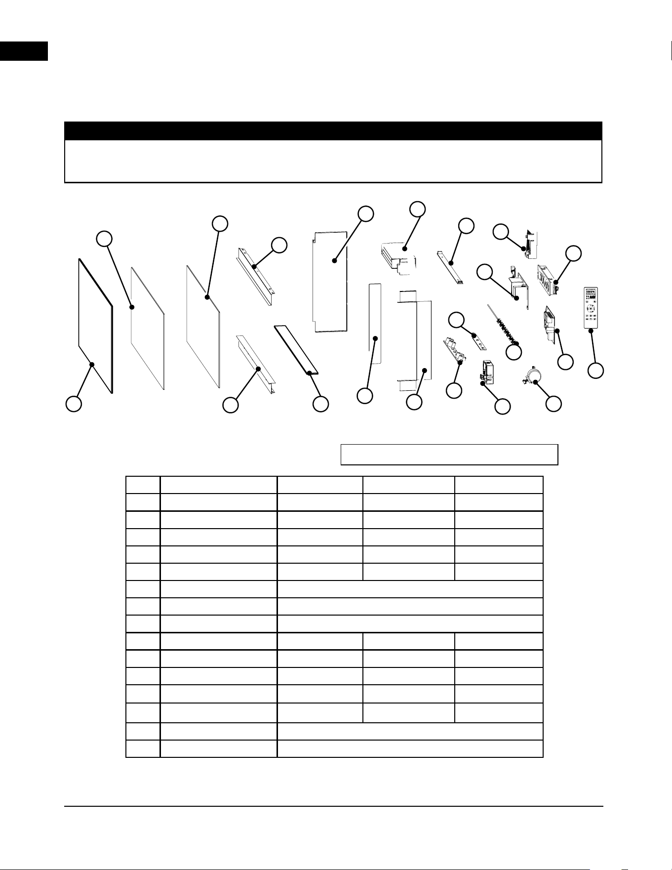
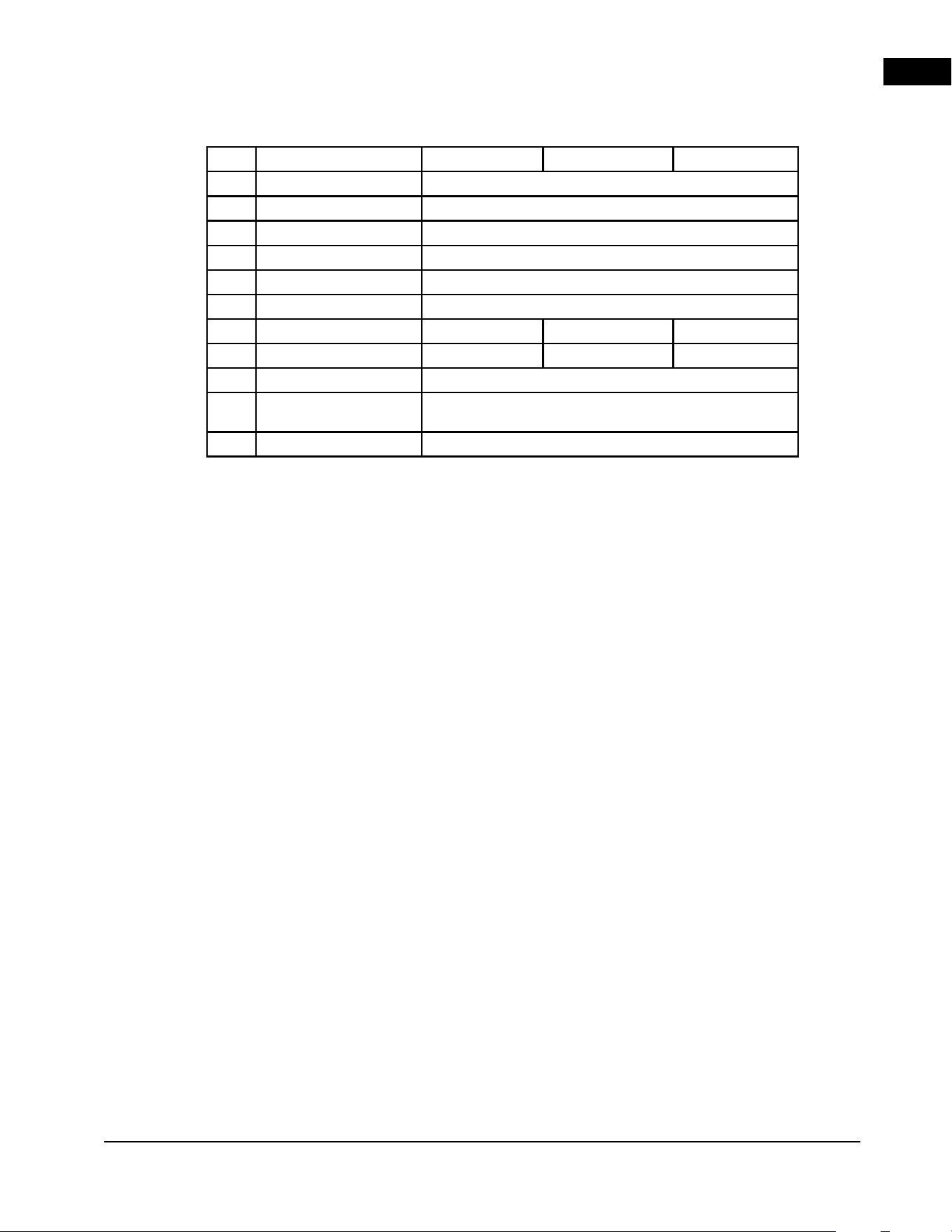
No. Description NEFL50AB-AU NEFL62AB-AU NEFL74AB-AU
1
Front Glass W300-0441 W300-0442 W300-0443
2
Plastic Flame Panel W565-0542 W565-0543 W565-0544
3
Glass Flame Panel W300-0446 W300-0447 W300-0448
4
Top recess Trim W715-1320 W715-1321 W715-1322
5
Bottom Recess trim W715-10000207 W715-10000210 W715-10000209
6
Recess Side Panel (closed) W715-1324 (2)
7
Recess Side trim (open) W715-1325 (2)
8
Side glass Panel W300-0450 (2)
9
Reflector W010-6266 W010-6267 W010-6268
10
Plastic Ember bed W497-1655 W497-1656 W497-1657
11
Flame LED strip W405-10000212 (4) W405-10000212 (5) W405-10000212 (6)
12
Top LED strip W405-10000213 (2) W405-10000213 (2) W405-10000213 (3)
13
Ember LED strip W405-10000214 (4) W405-10000214 (5) W405-10000214 (6)
14
Heater & Blower assembly W010-10007922
15
Main PCB Board W190-0259
9
5
13
6
2
14
21
11
4
19
1
20
12
15
3
8
16
18
7
10
17
9.1 NEFL50/62/74AB-AU
Care must be taken when removing and disposing of any broken glass or damaged components. Be sure to
vacuum away any broken glass from inside the appliance before operation.
note:
Items may not appear exactly as illustrated.
Table continued >
EN
replacement parts
A-0 | W415-10008161 | 45
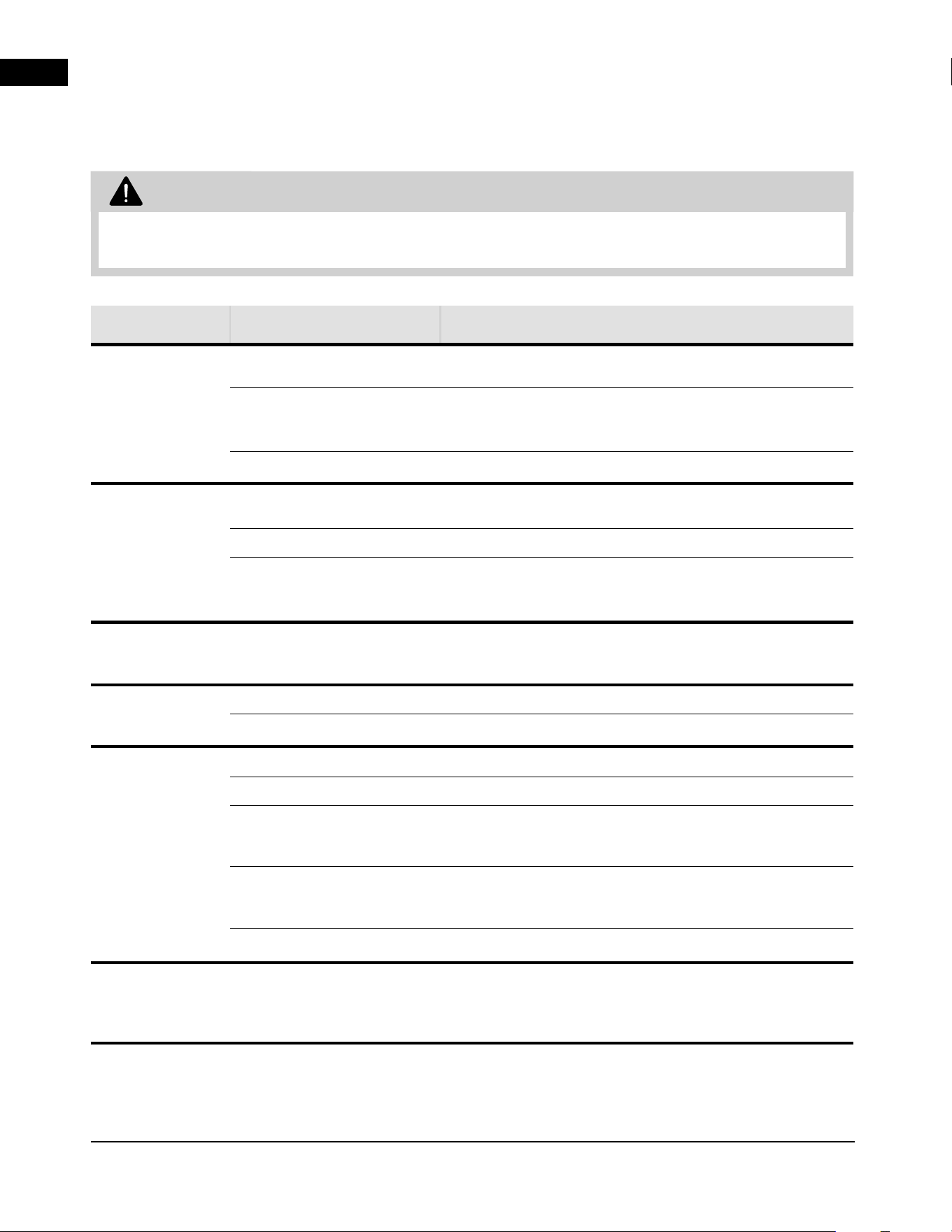
* Part not illustrated.
(#) Number in brackets indicates total number of parts in the fireplace. Order quantity is based on
actual Service requirements.
No. Description NEFL50AB-AU NEFL62AB-AU NEFL74AB-AU
16
Power Supply PCB W190-0260
17
Reflector motor W435-0090-SER
18
Touch Control Panel W190-0261
19
Remote Receiver W190-10000217
20
Temperature Sensor W190-10000219
21
Remote Control W190-0252
22*
Hardware Kit W370-0324 W370-0325 W370-0326
23*
Wire Harness W750-0541 W750-0542 W750-0543
24*
Wifi module PCB W010-6212
25*
120V/240V
Protection PCB
W190-10000220
26*
PCB Filter W190-10000221
EN
troubleshooting
46 | W415-10008161 | A-0
• Turn off the appliance completely and let cool before servicing. Only a qualified service person should
service and repair this electric appliance.
symptom problem solution
Appliance will not
come on when
power button/
switch is put into
the “on” position.
Appliance is not plugged into
an electrical outlet.
Check plug, and plug in the appliance if necessary.
Appliance has overheated
and safety thermal switch
has tripped.
Unplug power or turn off the circuit breaker, allow appliance
to cool for 15 minutes, then plug in the appliance or turn the
breaker on.
Main PCB board issue. Inspect the circuit board and replace, if necessary.
Appliance turns
off and will not
turn on.
House circuit breaker has
tripped.
Reset house circuit breaker.
Appliance’s fuse has blown. Replace the fuse.
Appliance has overheated
and safety thermal switch
has tripped.
Unplug power or turn off the circuit breaker, allow appliance to
cool for 15 minutes to reset the thermal switch, then plug in the
appliance or turn the breaker on.
Appliance has
returned to default
settings.
Power failure. Re-program appliance to original settings (not applicable with all
appliances).
Remote control
does not work.
Low/dead batteries. Replace batteries in remote control.
Remote receiver malfunction. Ensure remote receiver is not blocked. Replace control panel.
No warm air
coming out of the
appliance.
Heater setting not selected. See “operation” section.
Heater has been locked out. See “operation” section.
Room temperature is higher than
appliance setting (if set to room
temperature).
Reset temperature setting.
Appliance has overheated
and safety thermal switch
has tripped.
Unplug power or turn off the circuit breaker. Allow for appliance
to cool for 15 minutes.
Heater issue. Inspect the blower and heater and replace, if necessary.
Heater shuts off
automatically.
Room is too warm. The heater has a built-in thermostat so it will shut off
automatically once the pre-set temperature is reached. It will also
turn on automatically if the room temperature drops below the
pre-set temperature.
10.0 troubleshooting
WARNING
EN
troubleshooting
A-0 | W415-10008161 | 47
symptom problem solution
Dim or no flame Flame brightness not selected. See “operation” section.
Flame LEDs issue. Inspect the LED and replace, if necessary.
Main PCB board issue. Inspect the main PCB board and replace, if necessary.
Flame does
not move.
Motor is stalled/malfunctioning. Cycle on/off. If problem persists, consult dealer.
Ember bed is
not glowing or
dimming.
Brightness not selected. See “operation” section.
Ember LED issue. Inspect the ember bed LEDs and replace, if necessary.
Main PCB board issue. Inspect the main PCB board and replace, if necessary.
LED flashing
“OH”.
Appliance has overheated
and safety thermal switch
has tripped.
Unplug power or turn off the circuit breaker. Allow appliance to
cool for 15 minutes, then plug in the appliance or turn the breaker
on. If problem persists, consults your dealer.
LED flashing
“E-1”.
Error code for temperature
sensor.
Consult local service dealer.
Inspect / replace temperature sensor.
LED flashing
“E-2”.
Error code for blower.
Consult local service dealer.
Inspect wire harness / replace blower and heater assembly.
LED flashing
“E-3”.
Error code for heater Consult local service dealer.
Inspect wire harness / replace blower and heater assembly.
LED Flashing
“WIN”
Open Window Notification The fireplace has detected that the room temperature has
dropped significantly while the heater is on, indicating that a door
or window in the room is open and the fireplace is no longer
heating effectively and has turned off the heater to conserve
electricity.
Press and hold “X” and “OK” on remote while pointing at the
fireplace, or use the Napoleon Home App to reset the alert
notification. If the problem persists, consult your dealer.
Appliance will not
turn ON and Long
Continuous BEEP
when Power On /
Plugged in.
120/240V Protection PCB
has detected a fault in supply
connection. Consult local Service Dealer.
EN
warranty
48 | W415-10008161 | A-0
11.0 warranty
WARRANTY CONDITIONS AND LIMITATIONS
NAPOLEON ELECTRIC APPLIANCE
3 YEAR LIMITED WARRANTY
Napoleon electric appliances are
manufactured under the strict Standard of
the world recognized ISO 9001: 2015 Quality
Management System.
Napoleon products are designed with
superior components and materials and
assembled by trained craftsmen who take
great pride in their work. Once assembled,
the complete appliance is thoroughly
inspected by a qualifi ed and authorized
installer, service agency, or supplier before
packing to ensure that you, the customer,
receive the quality product that you expect
from Napoleon.
Electrical components and wearable parts
are covered, and Napoleon will provide
replacement parts free of charge during the
fi rst 3 years, beginning on the date of original
installation. This covers: fan/heaters, motors,
switches, nylon bearing components, remote
controls, and LED lights. * Light bulbs and
fuses are NOT covered by the warranty.
In the fi rst year only, any labour related to
warranty repair is covered.
* Construction of models vary. The warranty
applies only to components included with your
specifi c appliance.
Napoleon warrants its products against
manufacturing defects to the original
purchaser only.
Provided that the purchase was made
through an authorized Napoleon dealer, your
appliance is subject to the following conditions
and limitations:
Warranty coverage begins on the date of
original installation.
This factory warranty is non-transferable and
may not be extended whatsoever by any of our
representatives.
Installation must be done in accordance with the
installation instructions included with the product
and all local and national building and fi re codes.
This 3 year Limited Warranty does not
cover damage caused by misuse, lack of
maintenance, accident, alterations, abuse,
or neglect and parts installed from other
manufacturers will nullify this warranty.
This 3 year Limited Warranty further does
not cover any scratches, dents, corrosion,
or discolouring caused by excessive heat,
abrasive and chemical cleaners, nor chipping
on porcelain enamel parts, mechanical
breakage of PHAZER™ logs.
In the fi rst 3 years only, this warranty extends
to the repair or replacement of warranted parts
which are defective in material or workmanship,
provided that the product has been operated in
accordance with the operation instructions and
under normal conditions.
After the fi rst year, Napoleon will not be
responsible for installation, labour, or any
other expenses related to the reinstallation
of a warranted part, and such expenses are
not covered by this warranty. Notwithstanding
any provisions contained in the 3 year Limited
Warranty, Napoleon responsibility under this
warranty is defi ned as above, and it shall
not in any event extend to any incidental,
consequential, or indirect damages.
EN
warranty
A-0 | W415-10008161 | 49
All specifi cations and designs are subject to change without prior notice due to on-going product improvements.
Napoleon is a registered trademark of Wolf Steel Ltd.
This warranty defi nes the obligations and liability
of Napoleon with respect to the Napoleon
electric appliance and any other warranties
expressed or implied with respect to this product;
its components or accessories are excluded.
Napoleon neither assumes, nor authorizes any
third party to assume, on its behalf, any other
liabilities with respect to the sale of this product.
Any damage to appliance, brass trim or other
components due to water, weather damage,
long periods of dampness, condensation,
damaging chemicals, or cleaners will not be the
responsibility of Napoleon.
Napoleon reserves the right to have its
representative inspect any product or part
thereof prior to honouring any warranty claim.
All parts replaced under the 3 year Limited
Warranty Policy are subject to a single claim.
All parts replaced under the warranty will be
covered for a period of 90 days from the date of
their installation.
The manufacturer may require that defective
parts or products be returned or that digital
pictures be provided to support the claim.
Returned products are to be shipped prepaid to
the manufacturer for investigation. If a product
is found to be defective, the manufacturer will
repair or replace such defects.
Before shipping your appliance or defective
components, your dealer must obtain an
authorization number. Any merchandise shipped
without authorization will be refused and
returned to the sender.
Shipping costs are not covered under this
warranty.
Additional service fees may apply if you are
seeking a warranty service from a dealer.
EN
50 | W415-10008161 | A-0
EN
A-0 | W415-10008161 | 51
NAPOLEON
®
CELEBRATING OVER 40 YEARS
OF HOME COMFORT PRODUCTS
Address
Wolf Steel Ltd.
24 Napoleon Road, Barrie, Ontario, L4M 0G8, Canada
214 Bayview Drive, Barrie, Ontario, L4N 4Y8, Canada
103 Miller Drive, Crittenden, Kentucky, 41030, USA
7200 Trans Canada Highway,
Montreal, Quebec H4T 1A3, Canada
De Riemsdijk 22, 4004 LC Tiel, The Netherlands
Phone
Online
Canada
1-866-820-8686
www.napoleon.com