LAN
Video/User Guide/Support
NVR Security System
Quick Start Guide
Model: T8N00, T8E00, T8P00, T8P10
51005005531_V5
Anker Innovations Limited. All rights reserved, registered in the United States and
other countries.
The type and number of cameras vary by bundle package.
LAN
01
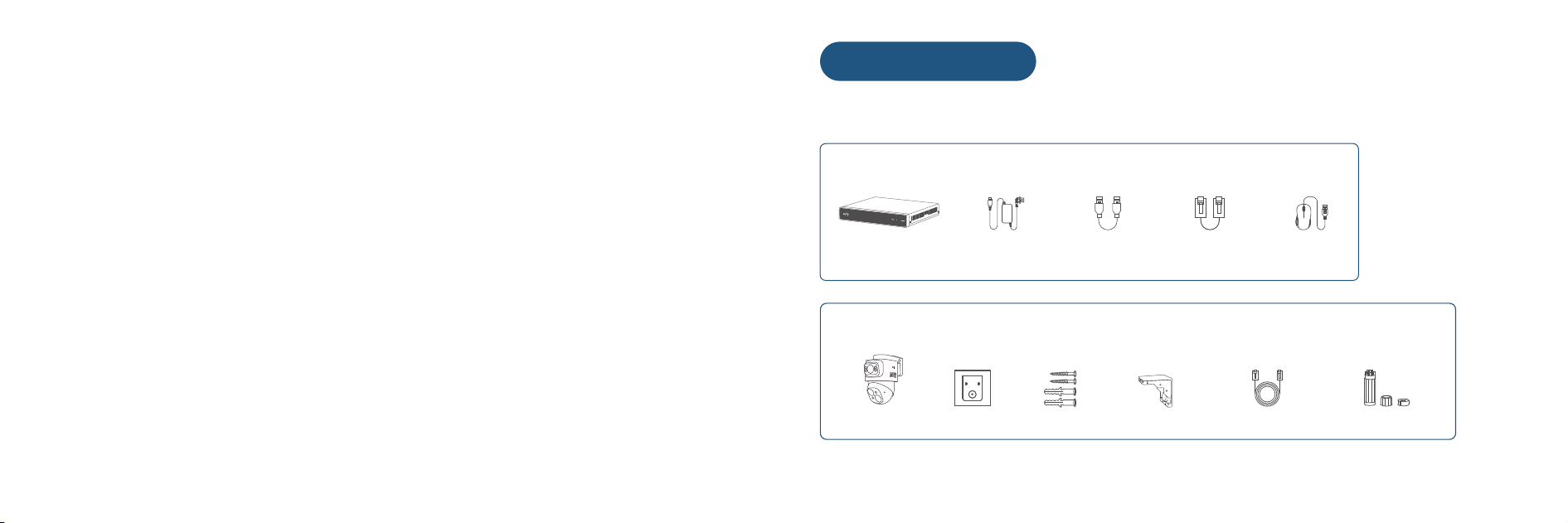
What's in the Box
Make sure everything is included. Anything missing? Please contact support@eufy.com.
For NVR Installation
For PoE Cam S4 Installation
Network Video Recorder S4
(with pre-installed 2TB hard
drive)
PoE Cam S4
Power Adapter
Positioning Sticker Screw Pack Mounting Bracket 18m Ethernet Cable Waterproof Cover Pack
HDMI Cable 1m Ethernet Cable USB Mouse
SYNC
DCIN AUDIO OUT USB HDMI LAN PoE1 PoE2 PoE3 PoE4 PoE5 PoE6 PoE7 PoE8TYPE-C
HDD LAN POWER
①
②
③
④ ⑤ ⑥ ⑦ ⑧ ⑨
⑩
① ② ③
④
0302
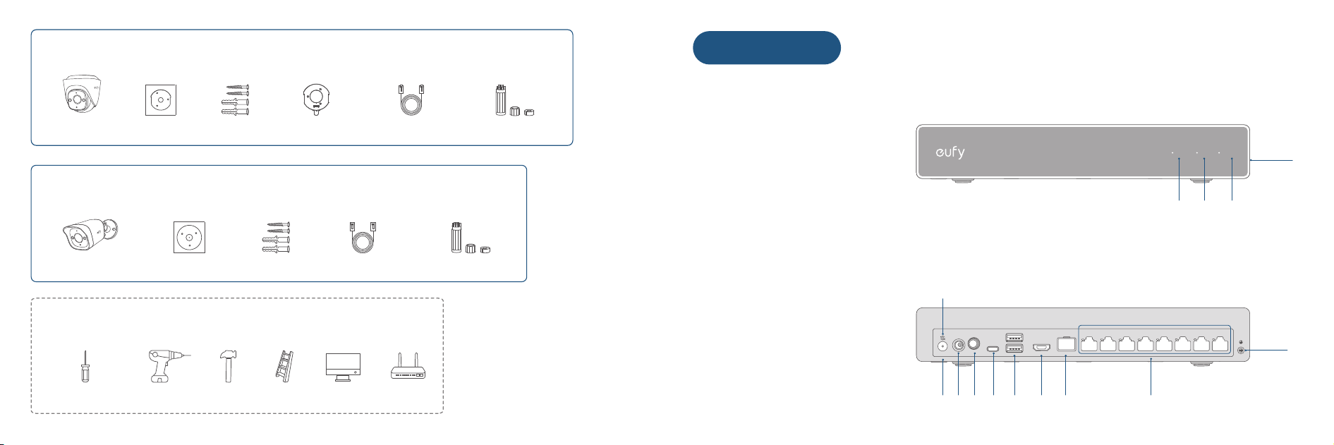
NVR
Front
① Hard Drive LED
② Network LED
③ Power LED
④ QR Code
Back
① SYNC Button
② Reset Hole
③ Power Port
④ Audio Output Port
⑤ USB-C Port
⑥ USB-A Port
⑦ HDMI Port
⑧ LAN Port
⑨ PoE Ports
⑩ Grounding Screw
For PoE Cam E41 Installation
For PoE Cam E40 Installation
Tools/Devices You will Need
PoE Cam E41
PoE Cam E40
Positioning Sticker
Positioning Sticker
Phillips Screwdriver Power Drill
13/16" (20.6 mm) & 1/4" (6.3 mm)
Screw Pack
Screw Pack
Hammer Ladder Monitor/TV Router
Mounting Bracket 18m Ethernet Cable
18m Ethernet Cable
Waterproof Cover Pack
Waterproof Cover Pack
At a Glance

SYNC
①
③
④
⑤
⑥
⑦
⑧
⑨
②
⑩
⑪
⑫
⑬
⑭
⑯
⑮
⑰
⑱
⑲
SYNC
①
③
④
⑤
⑥
⑦
⑧
⑨
②
⑩
⑪
⑫
⑬
0504
PoE Cam S4
PoE Cam E41
① Mounting Base
② Microphone
③ Camera Lens
④ Spotlight
⑤ LED Indicator
⑥ Speaker
⑦ Warning Light
⑧ Cable Notch
⑨ SYNC/Reset Button
⑩ SD Card Slot
⑪ Fusion Link Port
⑫ PoE Connector
⑬ DC Connector
① Mounting Base
②/⑩/⑫ Spotlight
③/④/⑧ Camera Lens
⑤ LED Indicator
⑥/⑨ Microphone
⑦ Warning Light
⑪ Speaker
⑬/⑭ Spring Screw
⑮ SD Card Slot
⑯ SYNC/Reset Button
⑰ Fusion Link Port
⑱ DC Connector
⑲ PoE Connector
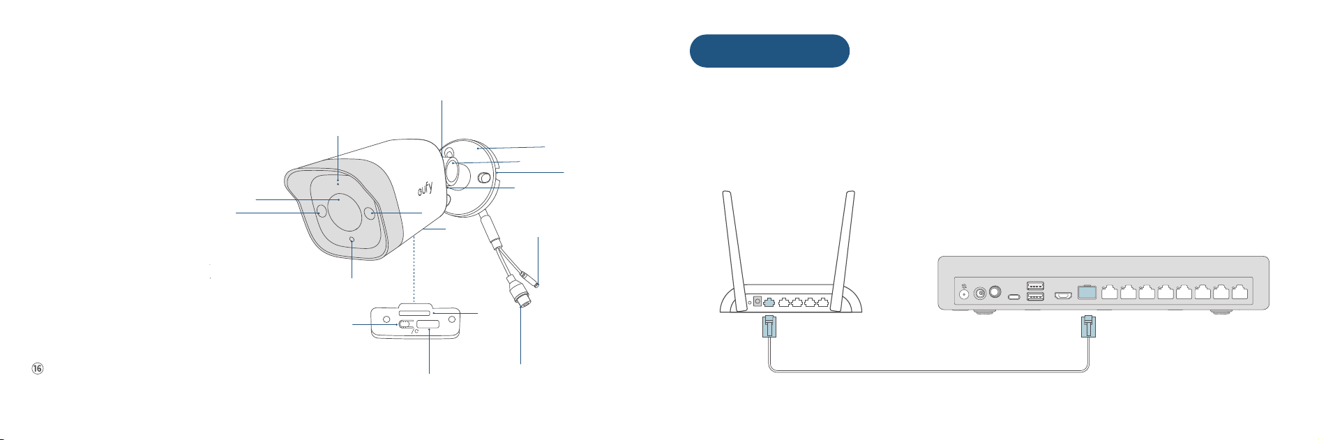
SYNC
①
③
④
⑤
⑥
⑦
⑧
⑨
②
⑩
⑪
⑫
⑬
⑭
⑮
⑯
0706
SYNC
DCIN AUDIO OUT USB HDMI LAN PoE1 PoE2 PoE3 PoE 4 PoE5 PoE 6 PoE7 PoE8TYPE-C
Getting Started
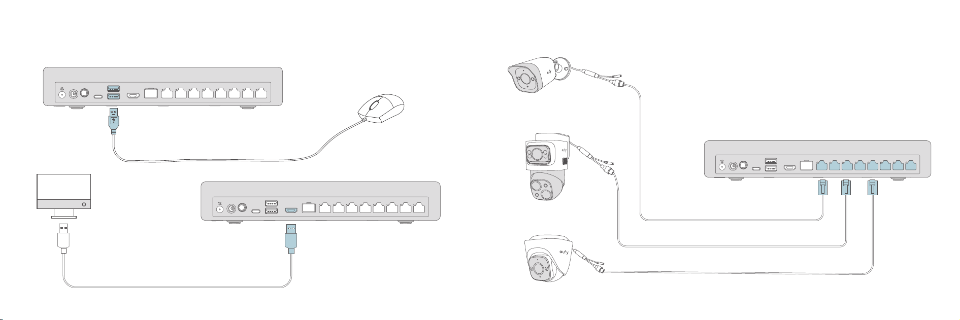
1 Connect the NVR Security System
❶ Connect NVR to Your Router
PoE Cam E40
① Microphone
② Camera Lens
③ Spotlight
④ LED Indicator
⑤ Warning Light
⑥ SYNC/Reset Button
⑦ SD Card Slot
⑧ Fusion Link Port
⑨ Camera Bottom Screw
⑩ Angle Adjustment Knob
⑪ Bracket Bottom Screw
⑫ Cable Notch
⑬ Mounting Bracket
⑭ PoE Connector
⑮ DC Connector
Speaker
0908
SYNC
DCIN AUDIO OUT USB HDMI LAN PoE1 PoE2 PoE3 PoE 4 PoE5 PoE6 P oE7 PoE8TYPE-C
SYNC
DCIN AUDIO OUT USB HDMI LAN PoE1 PoE2 PoE3 PoE 4 PoE5 PoE6 P oE7 PoE8TYPE-C
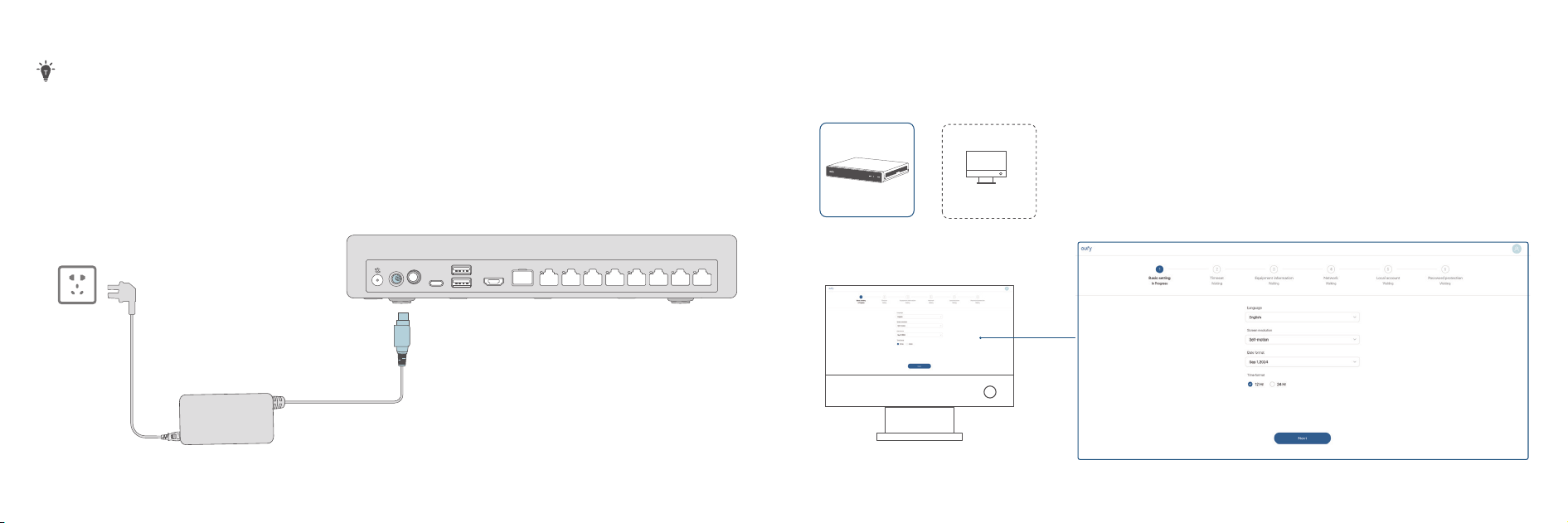
❷ Connect Mouse and Monitor to NVR ❸ Connect Cameras to NVR
SYNC
DCIN AUDIO OUT USB HDMI LAN PoE1 PoE2 PoE3 PoE4 PoE 5 PoE6 PoE7 PoE8TYPE-C
LAN
SYNC
DCIN AUDIO OUT USB HDMI LAN PoE1 PoE2 PoE3 PoE4 PoE5 PoE6 PoE7 PoE8TYPE-C
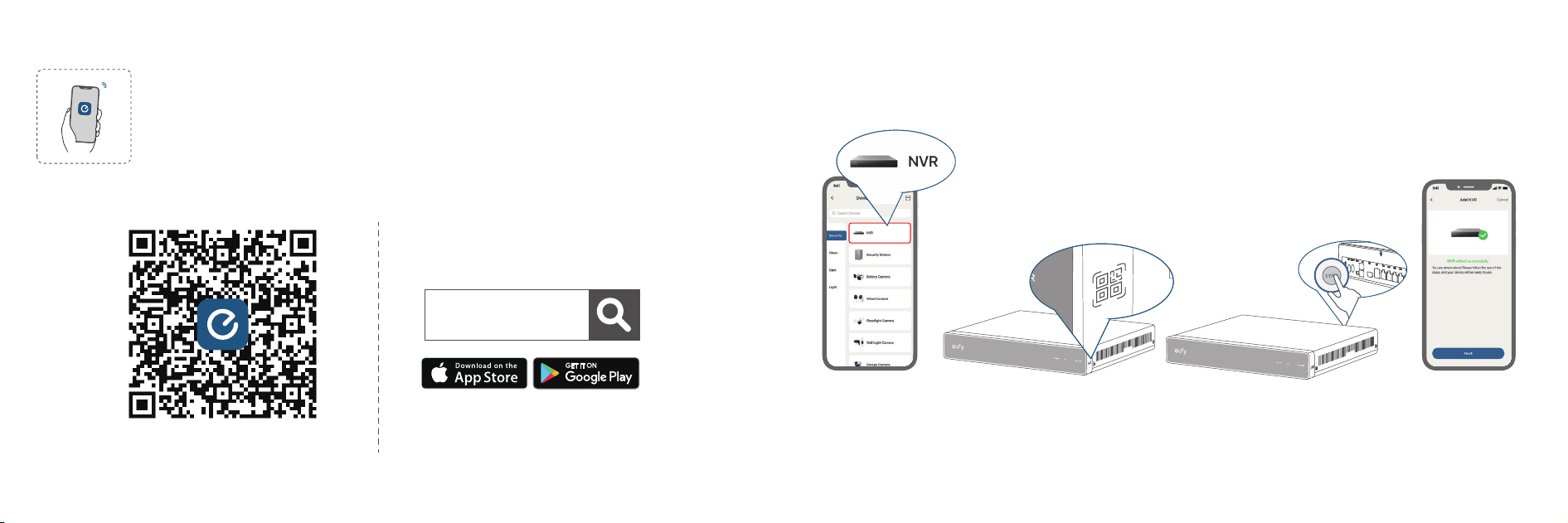
2 Set Up NVR Access
Option A - Set Up with Your Monitor/TV
1110
❹ Connect to Power Supply
Please leave a minimum clearance of 20 mm (0.78") on the le and right sides of the NVR for proper
ventilation.
LAN
LAN
eufy
① Download the eufy App
② Add NVR ④ Sync NVR③ Scan QR Code ⑤ Pair
1312
Option B - Connect NVR to the eufy App Follow in-app instructions to complete setup.
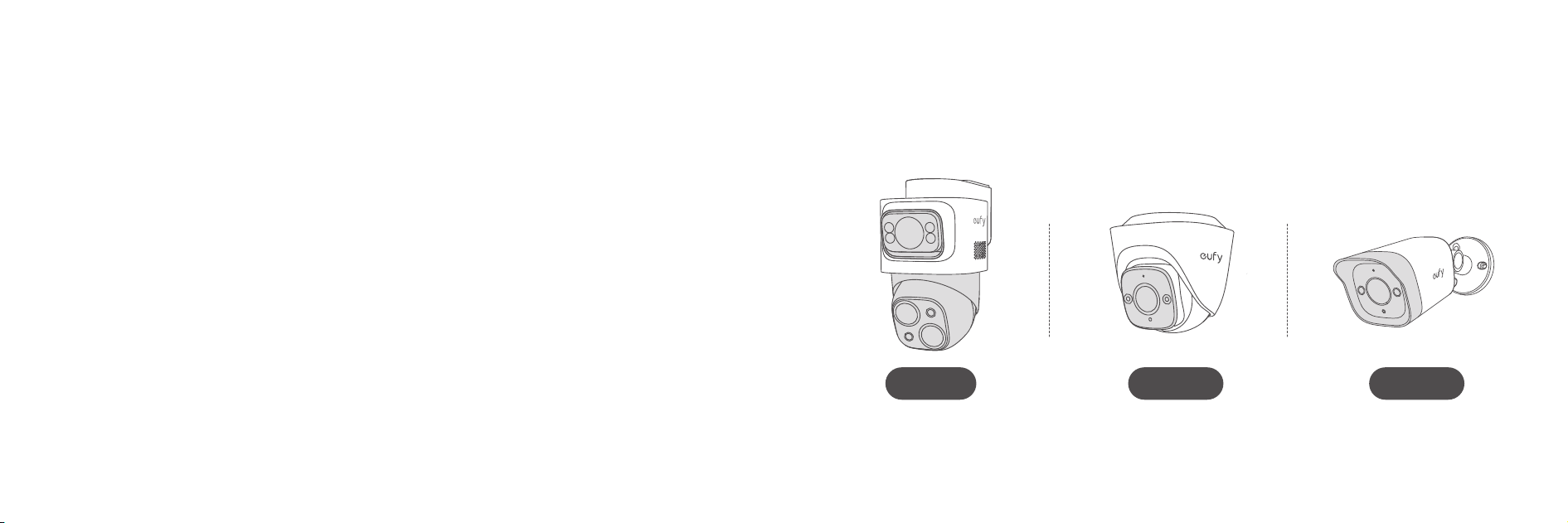
PoE Cam E40
PoE Cam E41
PoE Cam S4
3 Mount the Cameras
Page 16 Page 28 Page 41
1514
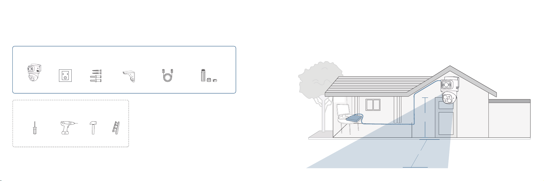
2-3 M
(7 to 10 )
20 M
(65 )
1716
Mounting PoE Cam S4
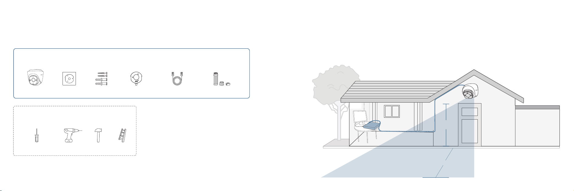
Step 1. Get Items Ready
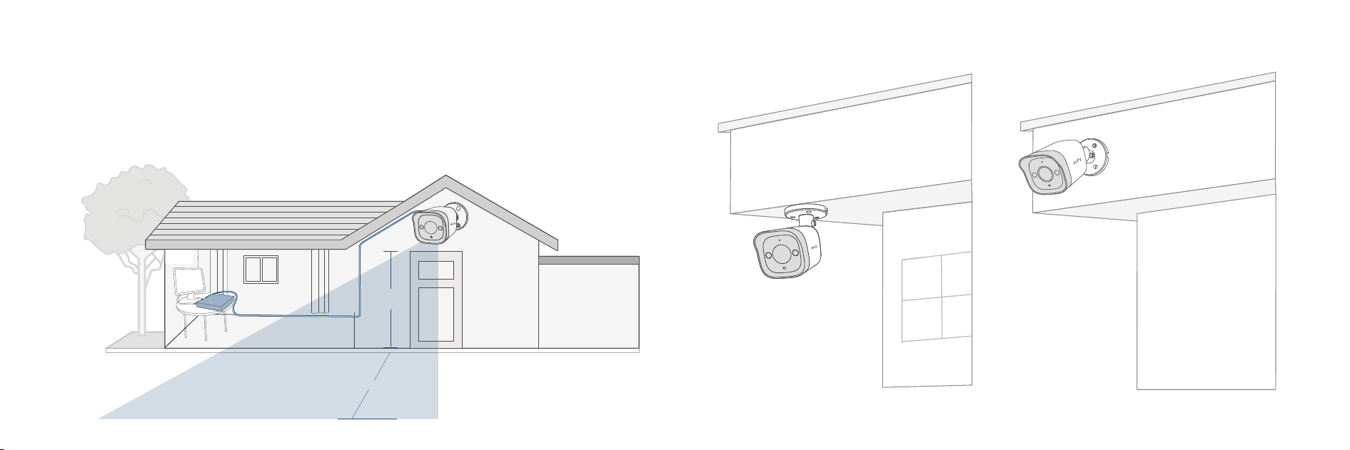
Step 2. Choose a Location
Recommended Location:
• Height of 2 m to 3 m (7 to 10 )
• 20 m (65) Field of View (for Telephoto Lens)
• On the Ceiling or on a Wall
For PoE Cam S4 Installation
PoE Cam S4
Positioning Sticker Screw Pack Mounting Bracket 18m Ethernet Cable
Waterproof Cover Pack
Tools/Devices You will Need
Phillips Screwdriver Power Drill
13/16" (20.6 mm) & 1/4" (6.3 mm)
Hammer Ladder
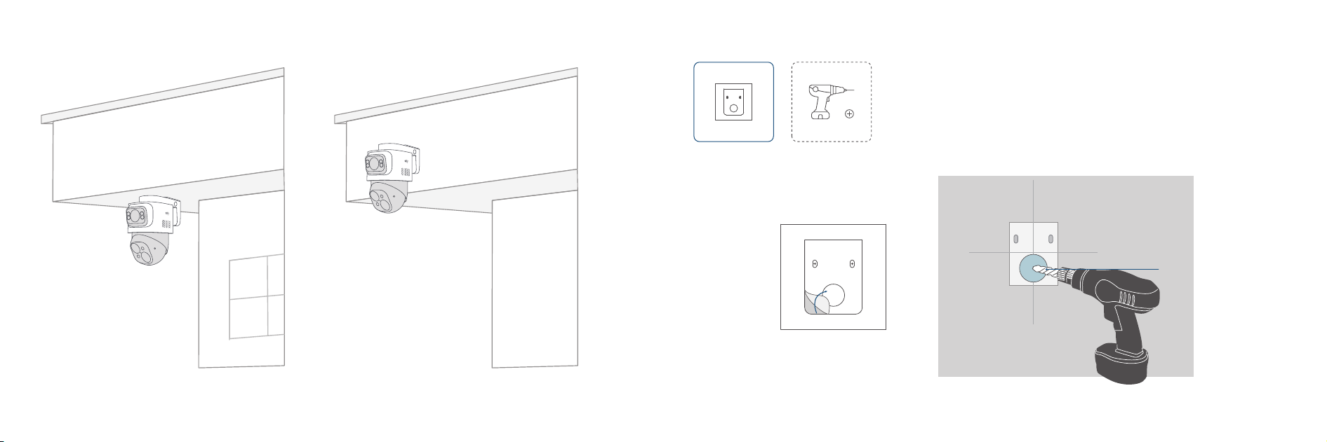
13/16" (20.6 mm)
13/16" (20.6 mm)
1918
On the Ceiling On the Wall
Step 3. Drill Cable Hole
①
Position
②
Drill Holes
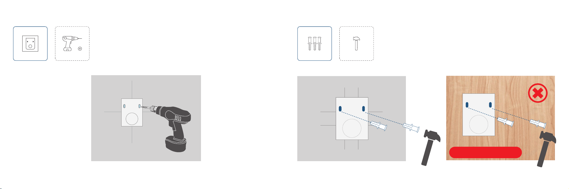
1/4" (6.3 mm)
2120
Step 4. Drill Screw Holes
Step 5. Insert Anchors
Skip for Wooden Walls
2322
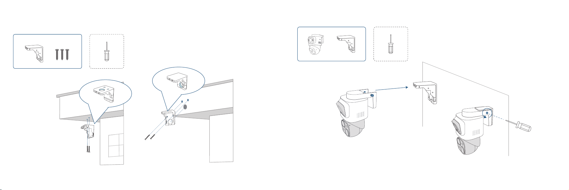
Step 6. Install the Mounting Bracket
This bracket can be installed either way —just attach the side with 3 holes to the wall/ceiling.
Ceiling Mounting Wall Mounting
Step 7. Mount the Camera
① Insert the Camera ② Lock the Spring Screws
❶
❷
❸
❹
Click
❶
❷
LAN
2524
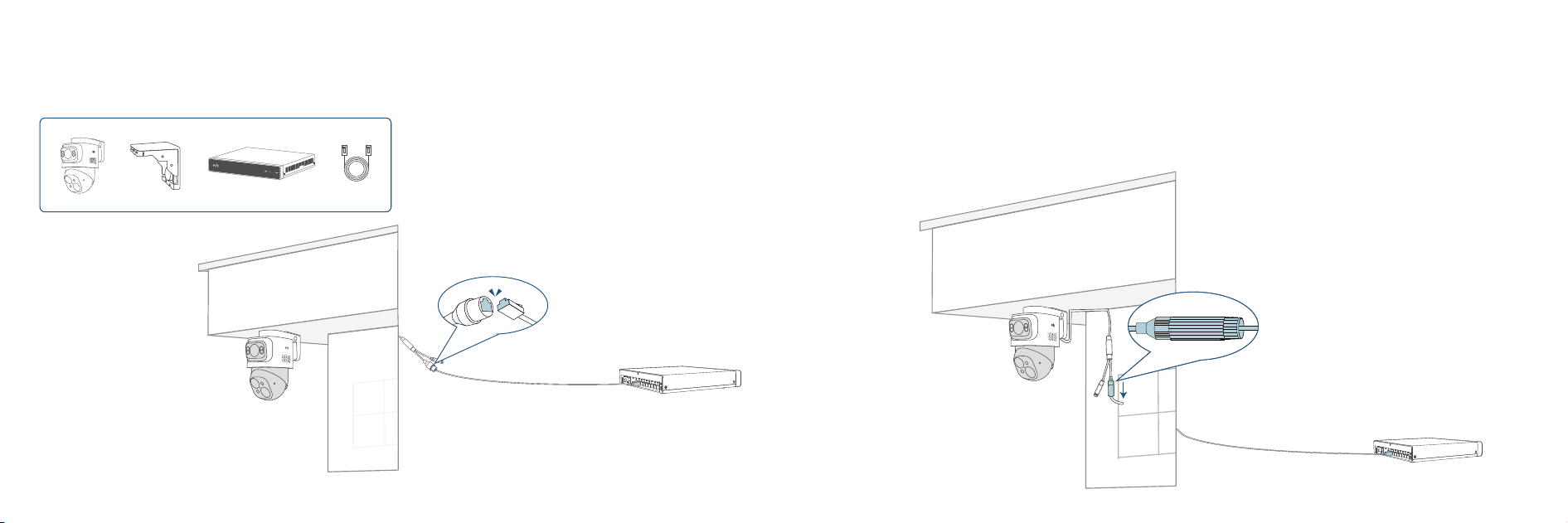
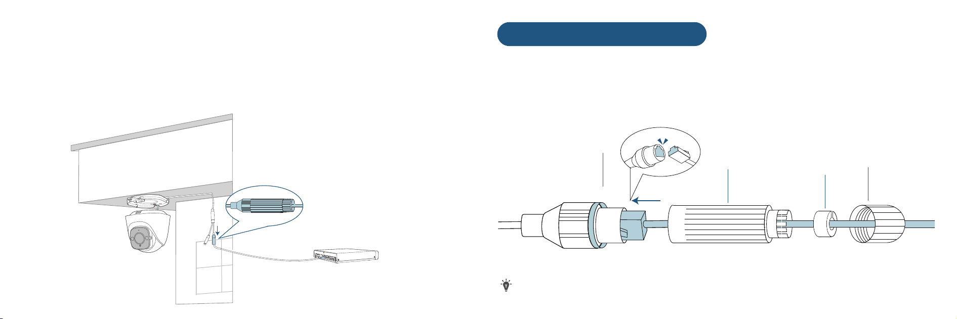
If the cable connector is exposed outside...
❶ Route the cable through the cable notch.
❷ Ensure the connector is positioned downward to prevent water intrusion.
❸ Install the waterproof cover and connect the camera with the Ethernet cable (next page).
❹ Ensure the Ethernet cable is connected to the NVR.
Step 8. Connect Camera to the NVR
❶ Connect the camera with the Ethernet cable.
❷ Ensure the Ethernet cable is connected to the NVR.
30°
180°
20°-90°
a
b
c d
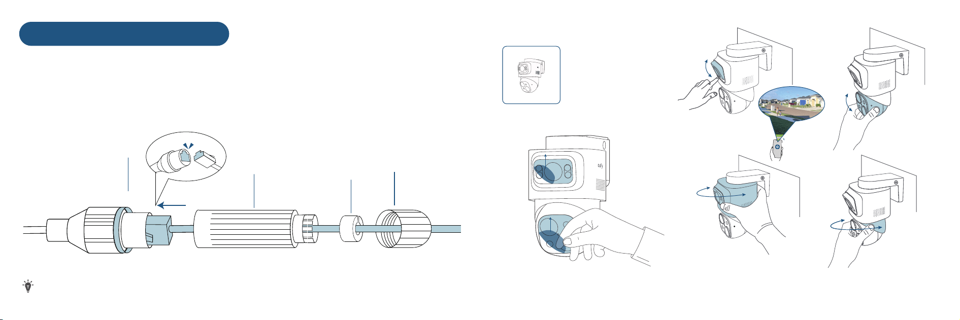
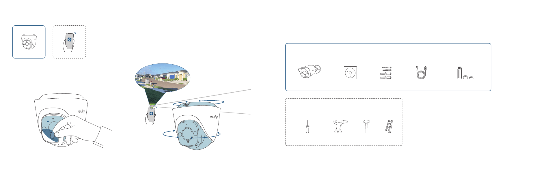
❶ Remove the Protective Film
• Rotate the Camera to the Optimal Angle
• Check the Live Stream in the App
❷
B
C
D
A
Click
Waterproofing Cable Connectors
❶ Ensure A is pre-installed on the PoE connector of the camera.
❷ Route the Ethernet cable through these components in order: B, C, and D.
❸ Plug the Ethernet cable into the camera PoE connector.
❹ Attach D with the camera PoE connector, and twist to lock.
❺ Insert C into D, and rotate B to secure it to D.
The shape of the waterproof cover and the connector may vary slightly.
2726
Step 9. Adjust the Camera Field of View
Tools/Devices You will Need
Phillips Screwdriver Power Drill
13/16" (20.6 mm) & 1/4" (6.3 mm)
Hammer Ladder
(7 to 10 )
12 m (39 )
2-3 M
2928
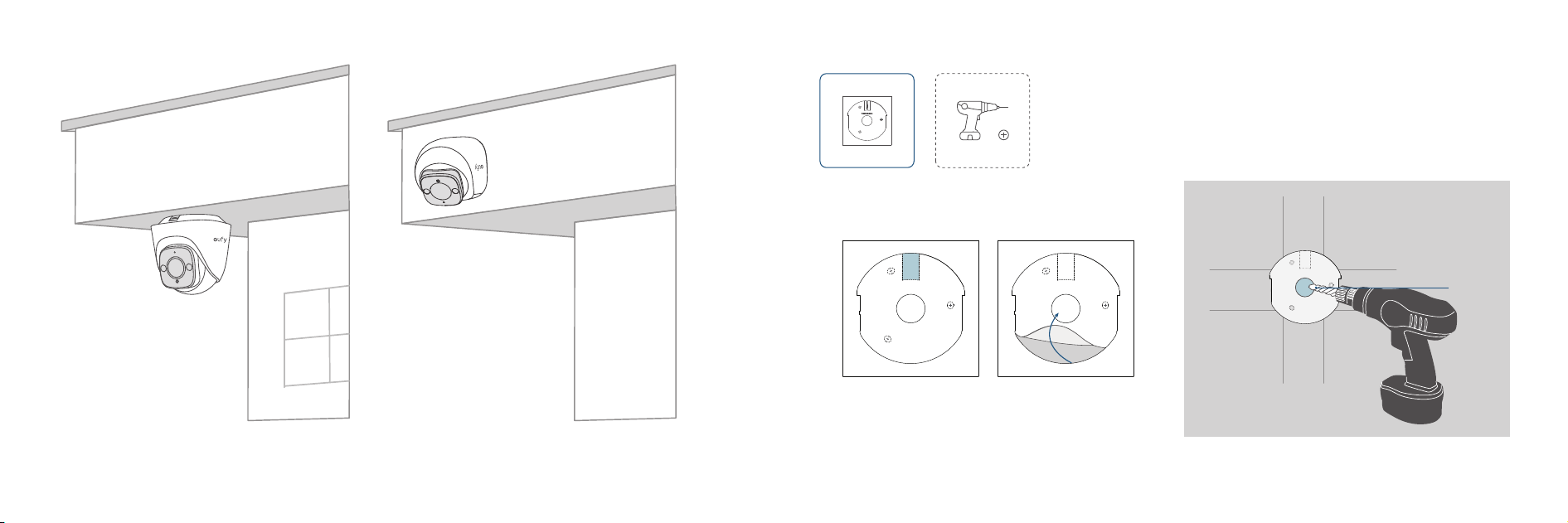
Mounting PoE Cam E41
Step 1. Get Items Ready
For PoE Cam E41 Installation
PoE Cam E41
Positioning Sticker Screw Pack Mounting Bracket 18m Ethernet Cable
Waterproof Cover Pack
Step 2. Choose a Location
Recommended Location:
• Height of 2 m to 3 m (7 to 10 )
• 12 m (39 ) Field of View
• On the Ceiling or on a Wall
PoE Cable Hole
CABLE TRAY
PoE Cable Hole
CABLE TRAY
PoE Cable Hole
CABLE TRAY
a b
13/16" (20.6 mm)
13/16" (20.6 mm)
3130
On the Ceiling On the Wall
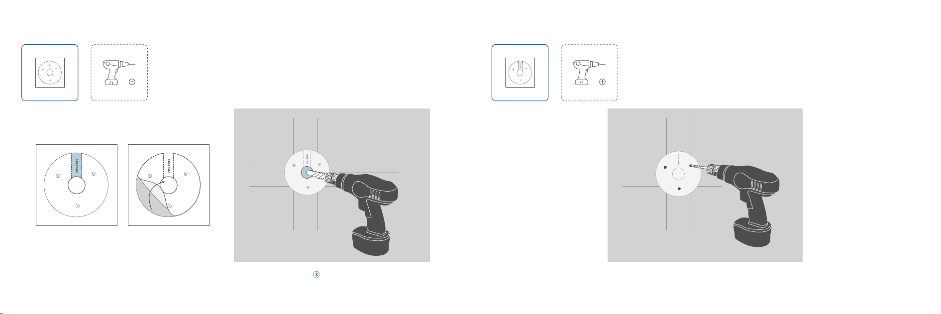
Step 3. Drill Cable Hole
① Determine
Cable Direction
③ Drill Holes
② Position
PoE Cable Hole
CABLE TRAY
PoE Cable Hole
CABLE TRAY
1/4" (6.3 mm)
3332
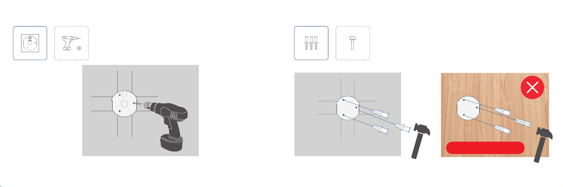
Step 4. Drill Screw Holes
Step 5. Insert Anchors
Skip for Wooden Walls
①
② ③
3534
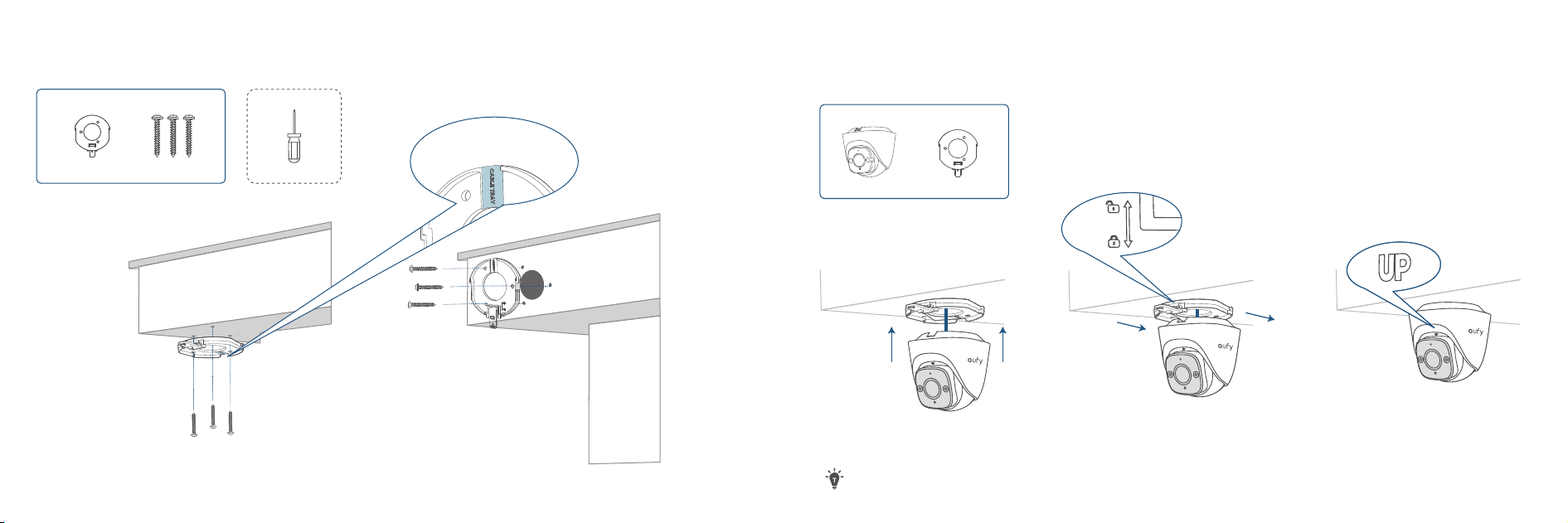
Step 6. Install the Mounting Bracket
On the Ceiling On the Wall
Route cable through
this notch.
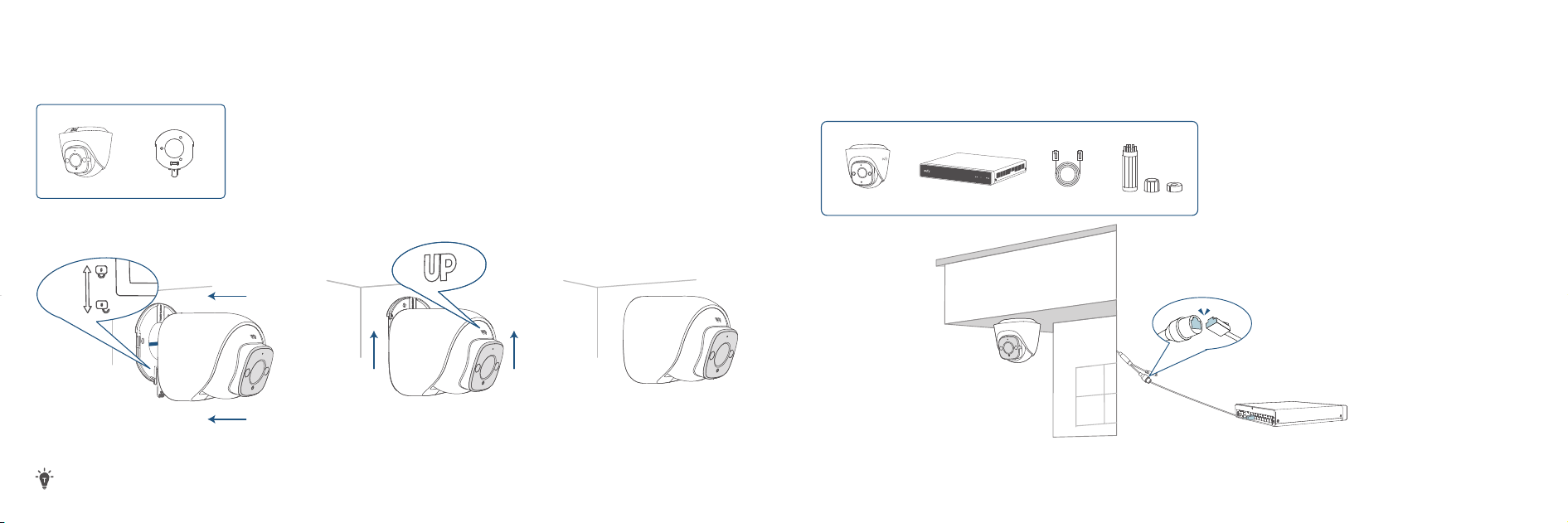
Step 7. Mount the Camera
Ceiling Mounting
Ensure the camera is ALWAYS positioned upright with the 'UP' mark facing upward; otherwise, the live stream image
will appear upside down.
LAN
❷
❶
Click
Step 8. Connect Camera to the NVR
❶ Connect the camera with the Ethernet cable.
❷ Ensure the Ethernet cable is connected to the NVR.
① ② ③
3736
Wall Mounting
Ensure the camera is ALWAYS positioned upright with the 'UP' mark facing upward; otherwise, the live stream image
will appear upside down.
❸
❷
❹
❶
B
C
D
A
Click
Waterproofing Cable Connectors
❶ Ensure A is pre-installed on the PoE connector of the camera.
❷ Route the Ethernet cable through these components in order: B, C, and D.
❸ Plug the Ethernet cable into the camera PoE connector.
❹ Attach D with the camera PoE connector, and twist to lock.
❺ Insert C into D, and rotate B to secure it to D.
The shape of the waterproof cover and the connector may vary slightly.
3938
If the cable connector is exposed outside...
❶ Route the cable through the cable notch.
❷ Ensure the connector is positioned downward to prevent water intrusion.
❸ Install the waterproof cover and connect the camera with the Ethernet cable (next page).
❹ Ensure the Ethernet cable is connected to the NVR.
360°
360°
Tools/Devices You will Need
Phillips Screwdriver Power Drill
13/16" (20.6 mm) & 1/4" (6.3 mm)
Hammer Ladder
4140
Step 9. Adjust the Camera Field of View
❶ Remove the Protective Film • Rotate the Camera to the Optimal Angle
• Check the Live Stream in the App
❷
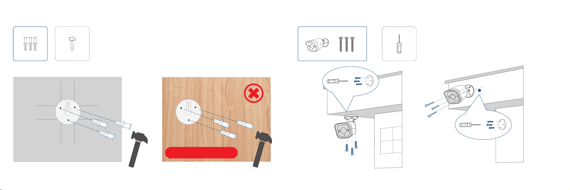
Mounting PoE Cam E40
Step 1. Get Items Ready
For PoE Cam E40 Installation
PoE Cam E40
Positioning Sticker Screw Pack 18m Ethernet Cable
Waterproof Cover Pack
2-3 M
(7 to 10 )
12 m (39 )
Step 2. Choose a Location
Recommended Location:
• Height of 2 m to 3 m (7 to 10 )
• 12 m (39 ) Field of View
• On the Ceiling or on a Wall
4342
On the Ceiling On the Wall
PoE Cable Hole
PoE Cable Hole
PoE Cable HolePoE Cable Hole
a b
13/16" (20.6 mm)
PoE Cable Hole
PoE Cable Hole
1/4" (6.3 mm)
13/16" (20.6 mm)
4544
Step 3. Drill Cable Hole
Drill Holes
① Determine
Cable Direction
② Position
Step 4. Drill Screw Holes
PoE Cable Hole PoE Cable Hole
4746
Step 5. Insert Anchors
Skip for Wooden Walls
Step 6. Mount the Camera
On the Ceiling On the Wall
Click
❶
❷
LAN
❹
❶
❷
❸
4948
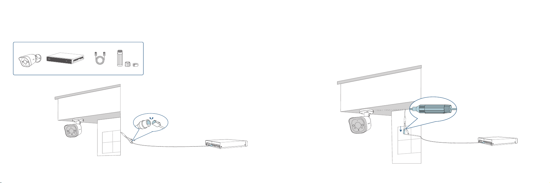
Step 7. Connect Camera to the NVR
❶ Connect the camera with the Ethernet cable.
❷ Ensure the Ethernet cable is connected to the NVR.
If the cable connector is exposed outside...
❶ Route the cable through the cable notch.
❷ Ensure the connector is positioned downward to prevent water intrusion.
❸ Install the waterproof cover and connect the camera with the Ethernet cable (next page).
❹ Ensure the Ethernet cable is connected to the NVR.
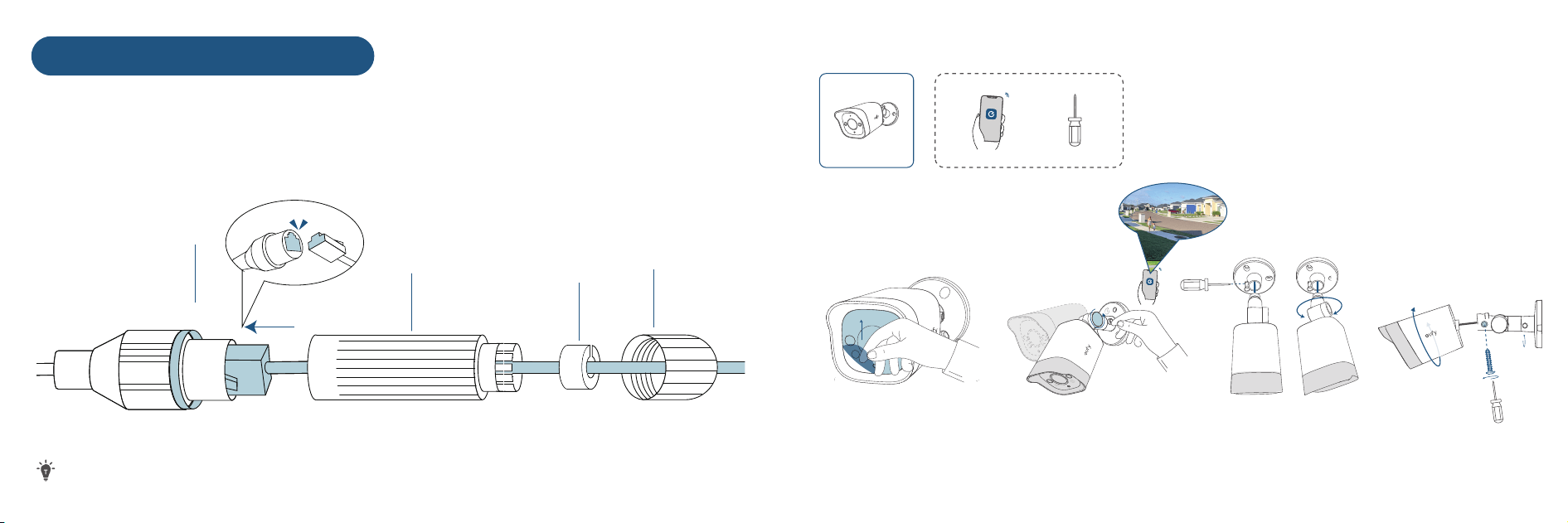
B
C
D
A
Click
❶ Ensure A is pre-installed on the PoE connector of the camera.
❷ Route the Ethernet cable through these components in order: B, C, and D.
❸ Plug the Ethernet cable into the camera PoE connector.
❹ Attach D with the camera PoE connector, and twist to lock.
❺ Insert C into D, and rotate B to secure it to D.
The shape of the waterproof cover and the connector may vary slightly.
5150
Waterproofing Cable Connectors
a
360°
b c
360°
Step 8. Adjust the Camera Field of View
❶ Remove the Protective Film
• Adjust the Knob or Screws to Get an Optimal Angle
• Check the Live Stream in the App
❷

5352
Now you're all set to use your NVR security system!
Congratulations!
Important Safety Instructions
• The recommended temperature range for T8P00, T8P10, and their accessories is -30°C to 50°C
(-22°F to 122°F).
• The recommended temperature range for T8E00 and their accessories is -30°C to 45°C (-22°F to
113°F).
• The recommended temperature range for T8N00 and accessories is -10°C to 40°C (14°F to 104°F).
• Unless specifically indicated that it is safe to do so in the user guide or instruction manual,
do not use the devices in an environment that exceeds the recommended low or high
temperature.
• Unless specifically indicated that it is safe to do so in the user guide or instruction manual,
avoid exposing your devices to direct sunshine or excessively wet environments.
• Do not use the product in any way other than described herein in order to avoid personal
injury or property damage.
• Users should comply with the laws and regulations of the corresponding countries and
regions where the equipment is located (used), abide by professional ethics, pay attention to
safety obligations, and strictly prohibit the use of our products or equipment for any illegal
purposes. Our company will not be responsible for any violators' legal liability under any
circumstances.
• For pluggable equipment, the socket outlet should be easily accessible.
• Use only the adapters provided by the manufacturer. Using unauthorized adapters may
cause danger and violate the Terms of Use and warranty article.

5554
Notice
FCC Statement
This device complies with Part 15 of the FCC Rules. Operation is subject to the following two
conditions: (1) this device may not cause harmful inteerence, and (2) this device must accept
any inteerence received, including inteerence that may cause undesired operation.
Warning: Changes or modifications not expressly approved by the party responsible for
compliance could void the user's authority to operate the equipment.
Note: This equipment has been tested and found to comply with the limits for a Class B digital
device, pursuant to Part 15 of the FCC Rules. These limits are designed to provide reasonable
protection against harmful inteerence in a residential installation.
This equipment generates uses and can radiate radio frequency energy and, if not installed
and used in accordance with the instructions, may cause harmful inteerence to radio
communications. However, there is no guarantee that inteerence will not occur in a particular
installation. If this equipment does cause harmful inteerence to radio or television reception,
which can be determined by turning the equipment o and on, the user is encouraged to try
to correct the inteerence by one or more of the following measures: (1) Reorient or relocate
the receiving antenna. (2) Increase the separation between the equipment and receiver. (3)
Connect the equipment into an outlet on a circuit dierent from that to which the receiver is
connected. (4) Consult the dealer or an experienced radio/TV technician for help.
The following importer is the responsible party
Company Name: POWER MOBILE LIFE, LLC
Address: 10800 NE 8TH ST #900, BELLEVUE, WA, 98004, UNITED STATES
Telephone: 1-800-988-7973
IC Statement
This device complies with Industry Canada licence-exempt RSS standard(s). Operation is
subject to the following two conditions:
(1) this device may not cause inteerence, and
(2) this device must accept any inteerence, including inteerence that may cause undesired
operation of the device.
This Class B digital apparatus complies with Canadian ICES-003.
The Adopted Trademarks HDMI, HDMI High-Definition Multimedia Inteace, HDMI trade dress and the HDMI Logos are
trademarks or registered trademarks of HDMI Licensing Administrator, Inc. in the United States and other countries.
5756
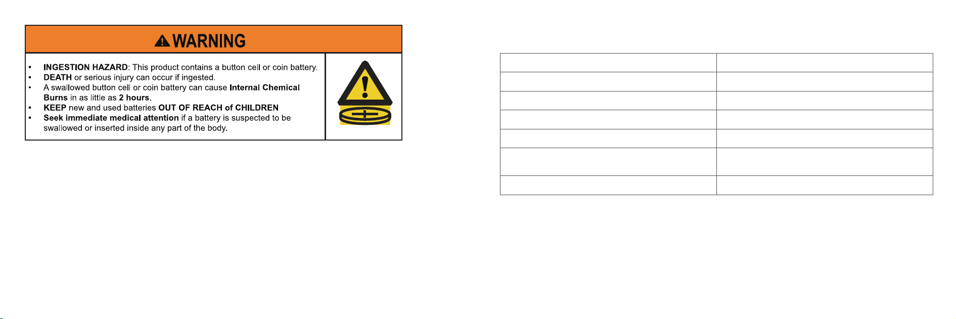
a) Remove and immediately recycle or dispose of used batteries according to local regulations
and keep away from children. Do NOT dispose of batteries in household trash or incinerate.
b) Even used batteries may cause severe injury or death.
c) Call a local poison control center for treatment information.
d) The compatible battery type CR2032 3V.
e) Non-rechargeable batteries are not to be recharged.
f) Do not force discharge, recharge, disassemble, heat above 45°C (113°F) or incinerate. Doing so
may result in injury due to venting, leakage or explosion resulting in chemical burns.
g) The product contains non-replaceable battery.
Warranty
Type Warranty Period
Network Video Recorder 36 Months
PoE Camera 36 Months
Hard Disk Drive / Mounting Bracket 24 Months
Power Adapter 18 Months
AC Cable / USB Mouse / Ethernet Cable /
HDMI Cable / Waterproof Cover Pack
12 Months
Other Accessories No Warranty
For more information about the warranty policy, please visit
https://www.eufy.com/policies/refund-policy?ref=navimenu_10_1_2_copy.
Customer Service
(US/Canada) +1 (800) 988 7973
support@eufy.com
support.au.eufy.com (AU)
Australian and New Zealand customers, please scan the QR code for the warranty
information.
Anker Innovations Limited
Unit 56, 8th Floor, Tower 2, Admiralty Centre, 18 Harcourt Road, Hong Kong
@EufyOicial
@EufyOicial
@EufyOicial