Model # P210
Made in China
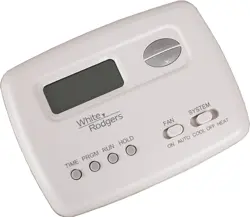
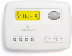
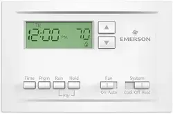
Single-Stage Thermostat
with scheduling
Install Guide
37-7578
Want to install the easy way?
2
GUIDE CONTENTS
Preparations ................................................. 3
Thermostat details ........................................ 4
Removal of your old thermostat.................... 5
Mounting and wiring your new thermostat .. 10
Checking thermostat operation................... 12
Programming your thermostat .................... 16
Specifications ............................................. 33
Troubleshooting .......................................... 35
Failure to follow and read all instructions carefully before installing or operating this control could cause personal injury
and/or property damage.
WARNING
!
3
1. PREPARATIONS
1.1 Check package contents
This package should contain the following items:
• Thermostat
• Mounting screws and wall anchors (x2)
• 2 AAA batteries
• Terminal wire label stickers
• Installation instructions
1.2 Gather tools
Required tools:
□ Flat-head Screwdriver □ Small pliers (needle-nose) □ Drill with 3/16” (4 mm) bit
Optional tools:
□ Wire cutters/stripper □ Hammer
4
2. THERMOSTAT DETAILS
1
2
3
4
5
6
7
8
9
10
11
12
13
14
15
16
17
18
19
20
1
2
3
4
5
6
7
8
9
10
11
12
13
14
15
16
17
18
19
20
1
2
3
4
5
6
7
8
9
10
11
12
13
14
15
16
17
18
19
20
1
2
3
4
5
6
7
8
9
10
11
12
13
14
15
16
17
18
19
20
1
2
3
4
5
6
7
8
9
10
11
12
13
14
15
16
17
18
19
20
1
2
3
4
5
6
7
8
9
10
11
12
13
14
15
16
17
18
19
20
1
2
3
4
5
6
7
8
9
10
11
12
13
14
15
16
17
18
19
20
1
2
3
4
5
6
7
8
9
10
11
12
13
14
15
16
17
18
19
20
Time Prgm Run Hold
Fltr
Fan
On Auto Cool Off Heat
System
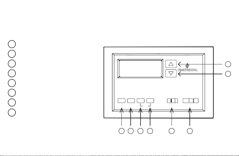
The thermostat buttons and switches
Raises temperature setting.
Lowers temperature setting.
TIME button.
PRGM (program) button.
RUN (run program) button.
HOLD temperature button.
FAN switch (ON, AUTO).
SYSTEM switch
(COOL, OFF, HEAT).
1
2
3
4
5
6
7
8
9
10
11
12
13
14
15
16
17
18
19
20
1
2
3
4
5
6
7
8
9
10
11
12
13
14
15
16
17
18
19
20
1
2
3
4
5
6
7
8
9
10
11
12
13
14
15
16
17
18
19
20
1
2
3
4
5
6
7
8
9
10
11
12
13
14
15
16
17
18
19
20
1
2
3
4
5
6
7
8
9
10
11
12
13
14
15
16
17
18
19
20
1
2
3
4
5
6
7
8
9
10
11
12
13
14
15
16
17
18
19
20
1
2
3
4
5
6
7
8
9
10
11
12
13
14
15
16
17
18
19
20
1
2
3
4
5
6
7
8
9
10
11
12
13
14
15
16
17
18
19
20
5
3. REMOVING OLD THERMOSTAT
3.1 Turn off power
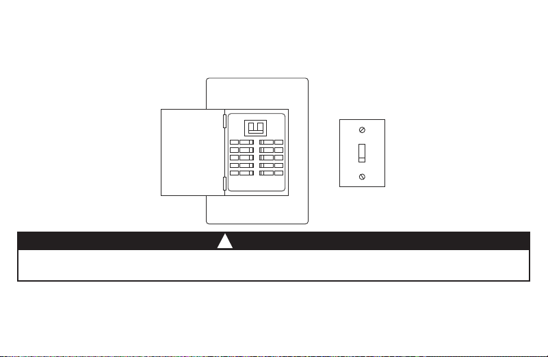
To prevent electrical shock and/or equipment damage, disconnect electrical power to the system at the main fuse or circuit breaker box, or by flipping
a switch at the air handler. Do not restore power until installation is complete.
WARNING
!
To ensure the power to your heating and cooling system has been turned off, try to turn on heating or cooling by
changing the temperature on your old thermostat.
or
6
3.2 Remove the old thermostat cover
Remove the old thermostat’s front cover from the wall base. Some covers pull off easily, while others may need to
be removed by prying the cover off with a screwdriver.
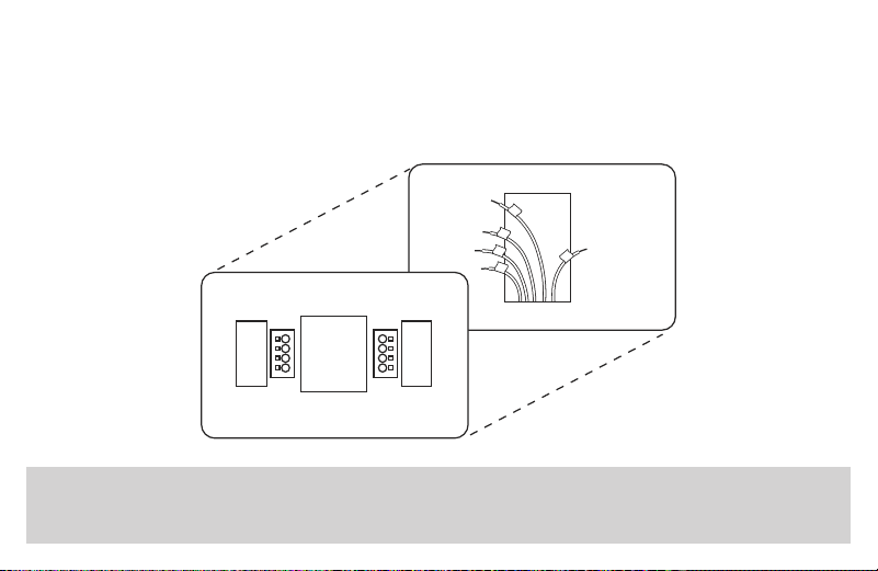
3.3 Label wires
Tip: Taking a picture with a camera or smartphone can help you not only remember how wires are connected
to the terminals, but can also ensure that you label your wires correctly.
Your old thermostat may have a sealed glass tube containing mercury. Be careful not to damage the tube or dispose of the tube in your trash.
For safe disposal information, please see Mercury Notice on page 43.
CAUTION
!
Using your screwdriver, carefully unscrew one wire at a time from the terminal block and attach the corresponding
wire label sticker.
Please note that not all terminals may be used, and that there’s no standard color code for thermostat wires, so
your wire colors may vary. For your reference, we’ve included a terminal label reference chart on page 7 to help you
connect the wires in your old thermostat to your new thermostat in case you get stuck.
7
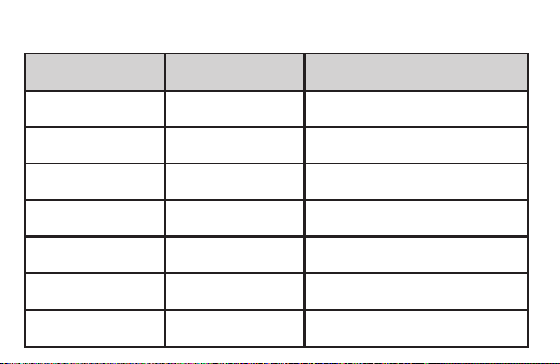
Terminal labeling reference chart
If your current terminal has
the following letter
Label the wires with the
following letters
Terminal function
RH, R, R5, 5 RH 24V Power (Heating)
RC RC 24V Power (Cooling)
W, W1, 4 W Heating Relay
Y, Y1 Y Cooling Relay
G G Fan Relay
O O
Reversing Valve (for heat pump applications
energized in Cool mode)
B B
Reversing Valve (for heat pump applications
energized in Heat mode)
8
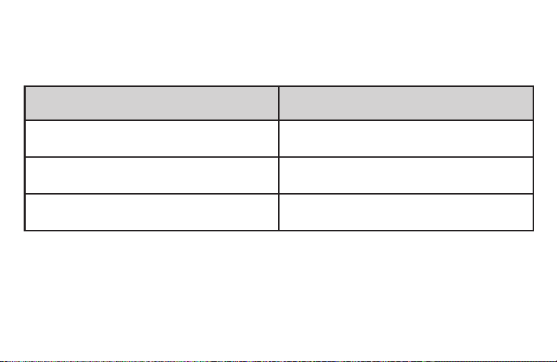
3.4 Identify jumper wire
On your old thermostat, if… Then, on your new thermostat…
Terminal RC and RH are connected
with a jumper wire
Leave the jumper wire in its place
There’s only one R wire (RC, RH, R or R5)
coming out of the wall
Leave the jumper wire in its place
Terminal RC and RH (or 5 or R5) are NOT
connected by a jumper wire
Remove the jumper wire between RC and RH
For terminal Y and W:
If you have a heat pump with reversing valve, connect Y and W with a jumper wire on your new thermostat.
If you need help with labeling and wiring, please contact Customer Support at 877.654.9394 or email
wr[email protected] — we’re here to help!
9
3.5 Remove old thermostat base
With all of your wires disconnected and properly labeled, you may now safely remove the thermostat base from
your wall.
Tip: Worried about having your wires falling into your wall? Keep the wires secure by wrapping the them
around a pencil.
10
4. MOUNTING AND WIRING YOUR NEW THERMOSTAT
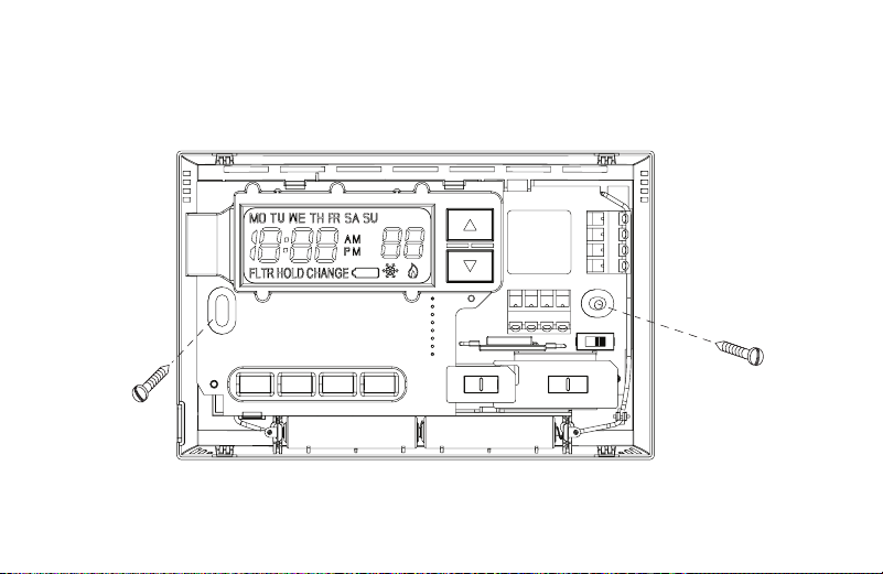
4.1 Install new thermostat base
Mount your new thermostat base using the supplied screws. Drill holes and insert wall anchors to secure the
thermostat base to the wall, if necessary.
11
4.2 Connect wires to corresponding terminal blocks
Match each labeled wire to it’s corresponding terminal on the mounted thermostat base. Insert each labeled wire into
the hole of it’s matching terminal, and using the screwdriver, tighten the screw on the terminal block securely.
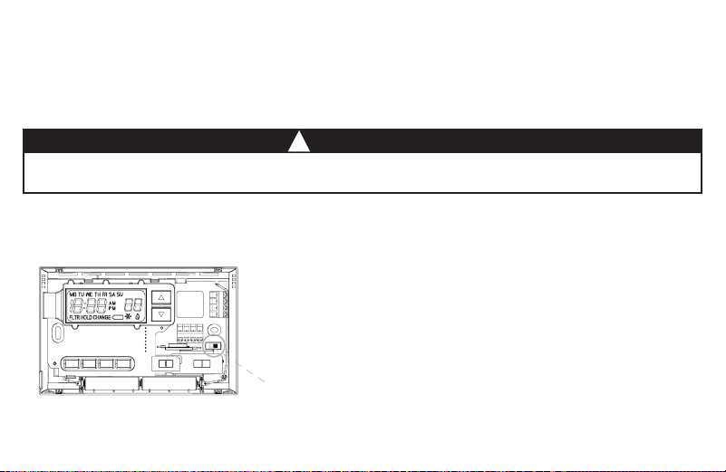
4.3 Set switch and advanced wiring
Take care when securing and routing wires so they do not short to adjacent terminals or rear of thermostat. Personal injury and/or property damage
may occur.
CAUTION
!
Electric / Gas
switch
If you have either a gas or oil furnace, set the switch to GAS.
If you have an electric furnace, set the switch to ELEC.
12
4.4 Install the batteries and attach front cover
Install the included AAA alkaline batteries and push the front cover on to the thermostat base until it’s secure.
4.5 Turn on power
Turn on your power at the source.
Congratulations! You’ve completed the thermostat installation process
5. CHECK THERMOSTAT OPERATION
5.1 Fan operation
If your system does not have a G terminal connection, skip to 5.2 Heating system.
1. Move FAN switch to ON position. The blower should begin to operate.
2. Move FAN switch to AUTO position. The blower should stop immediately.
Tip: If at any time during testing your system does not operate properly, please contact Customer Support at
877.654.9394 or email wr[email protected]
13
5.2 Heating system
1. Move SYSTEM switch to HEAT position. If the heating system has a standing pilot, be sure to light it.
2. Press to adjust thermostat setting room temperature. The heating system should begin to operate.
3. Press to adjust temperature setting below room temperature. The heating system should stop operating.
5.3 Cooling system
1. Move SYSTEM switch to COOL position.
2. Press to adjust thermostat setting below room temperature. The blower should come on immediately on high
speed, followed by bold air circulation.
3. Press to adjust temperature setting above room temperature. The cooling system should stop operating.
To prevent compressor and/or property damage, if the outdoor temperature is below 50°, DO NOT operate the cooling system
CAUTION
!
14
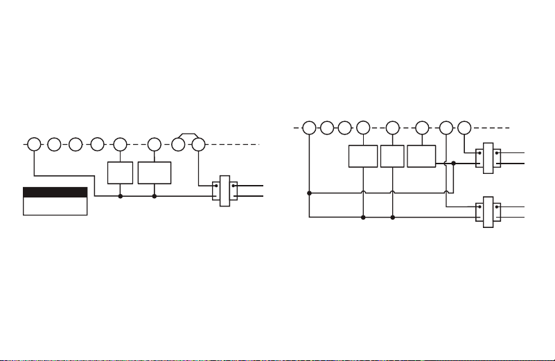
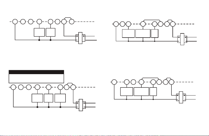
5.4 Typical wiring diagrams
Typical wiring diagram for heat only,
3-wire, single transformer systems
RH
24 VAC
120 VAC
Hot
Neutral
THERMOSTAT
SYSTEM
G W
TRANSFORMER
Heating
System
Fan
Relay
YC
‡
RC
JUMPER
WIRE
OB
For 2-wire Heat only,
attach to RH and W
NOTE
Typical wiring diagram for cool only,
3-wire, single transformer systems
RH
Y
24 VAC
120 VAC
Hot
Neutral
TRANSFORMER
THERMOSTAT
SYSTEM
G W
Cooling
System
Fan
Relay
RCOB
C
‡
JUMPER
WIRE
Typical wiring diagram for heat/cool,
4-wire, single transformer systems
RH
Y
24 VAC
120 VAC
Hot
Neutral
THERMOSTAT
SYSTEM
G W
TRANSFORMER
Heating
System
Fan
Relay
Cooling
System
RC
JUMPER
WIRE
OC
‡
B
RED jumper wire (provided with thermostat) must be
connected between thermostat RH and RC terminals
for proper thermostat operation with this system.
NOTE
Typical wiring diagram for heat/cool,
5-wire, two-transformer systems
RH
Y
24 VAC
120 VAC
Hot
Neutral
THERMOSTAT
SYSTEM
G W
HEATING
TRANSFORMER
Heating
System
Fan
Relay
Cooling
System
RC
24 VAC
120 VAC
Hot
Neutral
COOLING TRANSFORMER
OBC
‡
Typical wiring diagram for heat pump
with reversing valve energized in COOL
RH
Y
24 VAC
120 VAC
Hot
Neutral
THERMOSTAT
SYSTEM
G W
TRANSFORMER
Reversing
Valve*
RCOBC
‡
JUMPER
WIRE
Compressor
Contactor
JUMPER
WIRE
* Reversing valve is energized when the
system switch is in the COOL position
Fan
Relay
Typical wiring diagram for heat pump
with reversing valve energized in HEAT
RH
Y
24 VAC
120 VAC
Hot
Neutral
THERMOSTAT
SYSTEM
G W
TRANSFORMER
Reversing
Valve*
RCO
B
C
‡
JUMPER
WIRE
Compressor
Contactor
JUMPER
WIRE
* Reversing valve is energized when the
system switch is in the HEAT position
Fan
Relay
Typical wiring diagram for heat only,
3-wire, single transformer systems
RH
24 VAC
120 VAC
Hot
Neutral
THERMOSTAT
SYSTEM
G W
TRANSFORMER
Heating
System
Fan
Relay
YC
‡
RC
JUMPER
WIRE
OB
For 2-wire Heat only,
attach to RH and W
NOTE
Typical wiring diagram for cool only,
3-wire, single transformer systems
RH
Y
24 VAC
120 VAC
Hot
Neutral
TRANSFORMER
THERMOSTAT
SYSTEM
G W
Cooling
System
Fan
Relay
RCOB
C
‡
JUMPER
WIRE
Typical wiring diagram for heat/cool,
4-wire, single transformer systems
RH
Y
24 VAC
120 VAC
Hot
Neutral
THERMOSTAT
SYSTEM
G W
TRANSFORMER
Heating
System
Fan
Relay
Cooling
System
RC
JUMPER
WIRE
OC
‡
B
RED jumper wire (provided with thermostat) must be
connected between thermostat RH and RC terminals
for proper thermostat operation with this system.
NOTE
Typical wiring diagram for heat/cool,
5-wire, two-transformer systems
RH
Y
24 VAC
120 VAC
Hot
Neutral
THERMOSTAT
SYSTEM
G W
HEATING
TRANSFORMER
Heating
System
Fan
Relay
Cooling
System
RC
24 VAC
120 VAC
Hot
Neutral
COOLING TRANSFORMER
OBC
‡
Typical wiring diagram for heat pump
with reversing valve energized in COOL
RH
Y
24 VAC
120 VAC
Hot
Neutral
THERMOSTAT
SYSTEM
G W
TRANSFORMER
Reversing
Valve*
RCOBC
‡
JUMPER
WIRE
Compressor
Contactor
JUMPER
WIRE
* Reversing valve is energized when the
system switch is in the COOL position
Fan
Relay
Typical wiring diagram for heat pump
with reversing valve energized in HEAT
RH
Y
24 VAC
120 VAC
Hot
Neutral
THERMOSTAT
SYSTEM
G W
TRANSFORMER
Reversing
Valve*
RCO
B
C
‡
JUMPER
WIRE
Compressor
Contactor
JUMPER
WIRE
* Reversing valve is energized when the
system switch is in the HEAT position
Fan
Relay
15
Typical wiring diagram for heat only,
3-wire, single transformer systems
RH
24 VAC
120 VAC
Hot
Neutral
THERMOSTAT
SYSTEM
G W
TRANSFORMER
Heating
System
Fan
Relay
YC
‡
RC
JUMPER
WIRE
OB
For 2-wire Heat only,
attach to RH and W
NOTE
Typical wiring diagram for cool only,
3-wire, single transformer systems
RH
Y
24 VAC
120 VAC
Hot
Neutral
TRANSFORMER
THERMOSTAT
SYSTEM
G W
Cooling
System
Fan
Relay
RCOB
C
‡
JUMPER
WIRE
Typical wiring diagram for heat/cool,
4-wire, single transformer systems
RH
Y
24 VAC
120 VAC
Hot
Neutral
THERMOSTAT
SYSTEM
G W
TRANSFORMER
Heating
System
Fan
Relay
Cooling
System
RC
JUMPER
WIRE
OC
‡
B
RED jumper wire (provided with thermostat) must be
connected between thermostat RH and RC terminals
for proper thermostat operation with this system.
NOTE
Typical wiring diagram for heat/cool,
5-wire, two-transformer systems
RH
Y
24 VAC
120 VAC
Hot
Neutral
THERMOSTAT
SYSTEM
G W
HEATING
TRANSFORMER
Heating
System
Fan
Relay
Cooling
System
RC
24 VAC
120 VAC
Hot
Neutral
COOLING TRANSFORMER
OBC
‡
Typical wiring diagram for heat pump
with reversing valve energized in COOL
RH
Y
24 VAC
120 VAC
Hot
Neutral
THERMOSTAT
SYSTEM
G W
TRANSFORMER
Reversing
Valve*
RCOBC
‡
JUMPER
WIRE
Compressor
Contactor
JUMPER
WIRE
* Reversing valve is energized when the
system switch is in the COOL position
Fan
Relay
Typical wiring diagram for heat pump
with reversing valve energized in HEAT
RH
Y
24 VAC
120 VAC
Hot
Neutral
THERMOSTAT
SYSTEM
G W
TRANSFORMER
Reversing
Valve*
RCO
B
C
‡
JUMPER
WIRE
Compressor
Contactor
JUMPER
WIRE
* Reversing valve is energized when the
system switch is in the HEAT position
Fan
Relay
Typical wiring diagram for heat only,
3-wire, single transformer systems
RH
24 VAC
120 VAC
Hot
Neutral
THERMOSTAT
SYSTEM
G W
TRANSFORMER
Heating
System
Fan
Relay
YC
‡
RC
JUMPER
WIRE
OB
For 2-wire Heat only,
attach to RH and W
NOTE
Typical wiring diagram for cool only,
3-wire, single transformer systems
RH
Y
24 VAC
120 VAC
Hot
Neutral
TRANSFORMER
THERMOSTAT
SYSTEM
G W
Cooling
System
Fan
Relay
RCOB
C
‡
JUMPER
WIRE
Typical wiring diagram for heat/cool,
4-wire, single transformer systems
RH
Y
24 VAC
120 VAC
Hot
Neutral
THERMOSTAT
SYSTEM
G W
TRANSFORMER
Heating
System
Fan
Relay
Cooling
System
RC
JUMPER
WIRE
OC
‡
B
RED jumper wire (provided with thermostat) must be
connected between thermostat RH and RC terminals
for proper thermostat operation with this system.
NOTE
Typical wiring diagram for heat/cool,
5-wire, two-transformer systems
RH
Y
24 VAC
120 VAC
Hot
Neutral
THERMOSTAT
SYSTEM
G W
HEATING
TRANSFORMER
Heating
System
Fan
Relay
Cooling
System
RC
24 VAC
120 VAC
Hot
Neutral
COOLING TRANSFORMER
OBC
‡
Typical wiring diagram for heat pump
with reversing valve energized in COOL
RH
Y
24 VAC
120 VAC
Hot
Neutral
THERMOSTAT
SYSTEM
G W
TRANSFORMER
Reversing
Valve*
RCOBC
‡
JUMPER
WIRE
Compressor
Contactor
JUMPER
WIRE
* Reversing valve is energized when the
system switch is in the COOL position
Fan
Relay
Typical wiring diagram for heat pump
with reversing valve energized in HEAT
RH
Y
24 VAC
120 VAC
Hot
Neutral
THERMOSTAT
SYSTEM
G W
TRANSFORMER
Reversing
Valve*
RCO
B
C
‡
JUMPER
WIRE
Compressor
Contactor
JUMPER
WIRE
* Reversing valve is energized when the
system switch is in the HEAT position
Fan
Relay
Typical wiring diagram for heat only,
3-wire, single transformer systems
RH
24 VAC
120 VAC
Hot
Neutral
THERMOSTAT
SYSTEM
G W
TRANSFORMER
Heating
System
Fan
Relay
YC
‡
RC
JUMPER
WIRE
OB
For 2-wire Heat only,
attach to RH and W
NOTE
Typical wiring diagram for cool only,
3-wire, single transformer systems
RH
Y
24 VAC
120 VAC
Hot
Neutral
TRANSFORMER
THERMOSTAT
SYSTEM
G W
Cooling
System
Fan
Relay
RCOB
C
‡
JUMPER
WIRE
Typical wiring diagram for heat/cool,
4-wire, single transformer systems
RH
Y
24 VAC
120 VAC
Hot
Neutral
THERMOSTAT
SYSTEM
G W
TRANSFORMER
Heating
System
Fan
Relay
Cooling
System
RC
JUMPER
WIRE
OC
‡
B
RED jumper wire (provided with thermostat) must be
connected between thermostat RH and RC terminals
for proper thermostat operation with this system.
NOTE
Typical wiring diagram for heat/cool,
5-wire, two-transformer systems
RH
Y
24 VAC
120 VAC
Hot
Neutral
THERMOSTAT
SYSTEM
G W
HEATING
TRANSFORMER
Heating
System
Fan
Relay
Cooling
System
RC
24 VAC
120 VAC
Hot
Neutral
COOLING TRANSFORMER
OBC
‡
Typical wiring diagram for heat pump
with reversing valve energized in COOL
RH
Y
24 VAC
120 VAC
Hot
Neutral
THERMOSTAT
SYSTEM
G W
TRANSFORMER
Reversing
Valve*
RCOBC
‡
JUMPER
WIRE
Compressor
Contactor
JUMPER
WIRE
* Reversing valve is energized when the
system switch is in the COOL position
Fan
Relay
Typical wiring diagram for heat pump
with reversing valve energized in HEAT
RH
Y
24 VAC
120 VAC
Hot
Neutral
THERMOSTAT
SYSTEM
G W
TRANSFORMER
Reversing
Valve*
RCO
B
C
‡
JUMPER
WIRE
Compressor
Contactor
JUMPER
WIRE
* Reversing valve is energized when the
system switch is in the HEAT position
Fan
Relay
Typical wiring diagram for heat only,
3-wire, single transformer systems
RH
24 VAC
120 VAC
Hot
Neutral
THERMOSTAT
SYSTEM
G W
TRANSFORMER
Heating
System
Fan
Relay
YC
‡
RC
JUMPER
WIRE
OB
For 2-wire Heat only,
attach to RH and W
NOTE
Typical wiring diagram for cool only,
3-wire, single transformer systems
RH
Y
24 VAC
120 VAC
Hot
Neutral
TRANSFORMER
THERMOSTAT
SYSTEM
G W
Cooling
System
Fan
Relay
RCOB
C
‡
JUMPER
WIRE
Typical wiring diagram for heat/cool,
4-wire, single transformer systems
RH
Y
24 VAC
120 VAC
Hot
Neutral
THERMOSTAT
SYSTEM
G W
TRANSFORMER
Heating
System
Fan
Relay
Cooling
System
RC
JUMPER
WIRE
OC
‡
B
RED jumper wire (provided with thermostat) must be
connected between thermostat RH and RC terminals
for proper thermostat operation with this system.
NOTE
Typical wiring diagram for heat/cool,
5-wire, two-transformer systems
RH
Y
24 VAC
120 VAC
Hot
Neutral
THERMOSTAT
SYSTEM
G W
HEATING
TRANSFORMER
Heating
System
Fan
Relay
Cooling
System
RC
24 VAC
120 VAC
Hot
Neutral
COOLING TRANSFORMER
OBC
‡
Typical wiring diagram for heat pump
with reversing valve energized in COOL
RH
Y
24 VAC
120 VAC
Hot
Neutral
THERMOSTAT
SYSTEM
G W
TRANSFORMER
Reversing
Valve*
RCOBC
‡
JUMPER
WIRE
Compressor
Contactor
JUMPER
WIRE
* Reversing valve is energized when the
system switch is in the COOL position
Fan
Relay
Typical wiring diagram for heat pump
with reversing valve energized in HEAT
RH
Y
24 VAC
120 VAC
Hot
Neutral
THERMOSTAT
SYSTEM
G W
TRANSFORMER
Reversing
Valve*
RCO
B
C
‡
JUMPER
WIRE
Compressor
Contactor
JUMPER
WIRE
* Reversing valve is energized when the
system switch is in the HEAT position
Fan
Relay
ǂ c-wire not required
16
6. PROGRAMMING YOUR THERMOSTAT
Before you begin programming your thermostat, you should be familiar with its features and with the display and the
location and operation of the thermostat buttons. Your thermostat consists of two parts: the thermostat cover and the
base. To remove the cover, pull it straight out from the base. To replace the cover, line up the cover with the base
and press until the cover snaps onto the base.
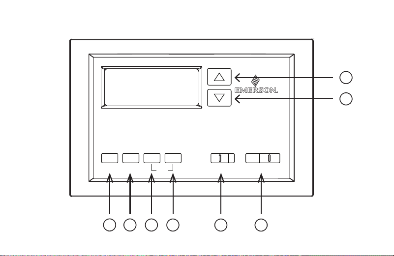
6.1 The thermostat buttons and switches
Raises temperature setting.
Lowers temperature setting.
TIME button.
PRGM (program) button.
RUN (run program) button.
HOLD temperature button.
FAN switch (ON, AUTO).
SYSTEM switch (COOL, OFF, HEAT).
1
2
3
4
5
6
7
8
9
10
11
12
13
14
15
16
17
18
19
20
1
2
3
4
5
6
7
8
9
10
11
12
13
14
15
16
17
18
19
20
1
2
3
4
5
6
7
8
9
10
11
12
13
14
15
16
17
18
19
20
1
2
3
4
5
6
7
8
9
10
11
12
13
14
15
16
17
18
19
20
1
2
3
4
5
6
7
8
9
10
11
12
13
14
15
16
17
18
19
20
1
2
3
4
5
6
7
8
9
10
11
12
13
14
15
16
17
18
19
20
1
2
3
4
5
6
7
8
9
10
11
12
13
14
15
16
17
18
19
20
1
2
3
4
5
6
7
8
9
10
11
12
13
14
15
16
17
18
19
20
17
1
2
3
4
5
6
7
8
9
10
11
12
13
14
15
16
17
18
19
20
1
2
3
4
5
6
7
8
9
10
11
12
13
14
15
16
17
18
19
20
1
2
3
4
5
6
7
8
9
10
11
12
13
14
15
16
17
18
19
20
1
2
3
4
5
6
7
8
9
10
11
12
13
14
15
16
17
18
19
20
1
2
3
4
5
6
7
8
9
10
11
12
13
14
15
16
17
18
19
20
1
2
3
4
5
6
7
8
9
10
11
12
13
14
15
16
17
18
19
20
1
2
3
4
5
6
7
8
9
10
11
12
13
14
15
16
17
18
19
20
1
2
3
4
5
6
7
8
9
10
11
12
13
14
15
16
17
18
19
20
Time Prgm Run Hold
Fltr
Fan
On Auto Cool Off Heat
System
18
6.2 The display
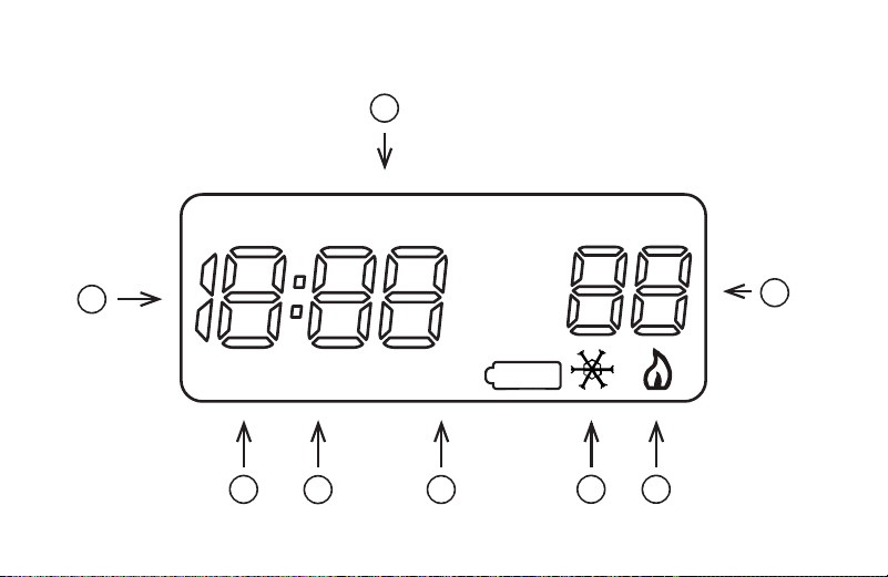
Indicates day of the week.
Flame icon () is displayed when the SYSTEM switch is in the HEAT position. Snowake
icon ()is displayed (non-flashing) when the SYSTEM switch is in the COOL position.
Snowake is displayed (flashing) if the thermostat is in lockout mode to prevent the
compressor from cycling too quickly.
Displays “CHANGE ” when the 2 "AAA" batteries are low and should be replaced.
Only “CHANGE ” and “LO” in the minutes eld are displayed when batteries are low
with no system power.
Alternately displays current time and temperature. Displays “LO” in the minutes eld when
batteries are low.
The word “HOLD” is displayed when the thermostat is in the HOLD mode. “HOLD” is
displayed flashing when the thermostat is in a temporary HOLD Mode.
Displays currently programmed set temperature (this is blank when SYSTEM switch is
in the OFF position).
Displays “FLTR” when the system has run for the programmed lter time period as a
reminder to change or clean your air lter.
1
2
3
4
5
6
7
8
9
10
11
12
13
14
15
16
17
18
19
20
1
2
3
4
5
6
7
8
9
10
11
12
13
14
15
16
17
18
19
20
1
2
3
4
5
6
7
8
9
10
11
12
13
14
15
16
17
18
19
20
1
2
3
4
5
6
7
8
9
10
11
12
13
14
15
16
17
18
19
20
1
2
3
4
5
6
7
8
9
10
11
12
13
14
15
16
17
18
19
20
1
2
3
4
5
6
7
8
9
10
11
12
13
14
15
16
17
18
19
20
1
2
3
4
5
6
7
8
9
10
11
12
13
14
15
16
17
18
19
20
19
1
2
3
4
5
6
7
8
9
10
11
12
13
14
15
16
17
18
19
20
1
2
3
4
5
6
7
8
9
10
11
12
13
14
15
16
17
18
19
20
1
2
3
4
5
6
7
8
9
10
11
12
13
14
15
16
17
18
19
20
1
2
3
4
5
6
7
8
9
10
11
12
13
14
15
16
17
18
19
20
1
2
3
4
5
6
7
8
9
10
11
12
13
14
15
16
17
18
19
20
1
2
3
4
5
6
7
8
9
10
11
12
13
14
15
16
17
18
19
20
1
2
3
4
5
6
7
8
9
10
11
12
13
14
15
16
17
18
19
20
1
2
3
4
5
6
7
8
9
10
11
12
13
14
15
16
17
18
19
20
FLTR HOLDCHANGE
PM
AM
MO TU WE TH FR SA SU

20
6.3 Conguration menu
The conguration menu allows you to set certain thermostat operating characteristics to your system or personal
requirements.
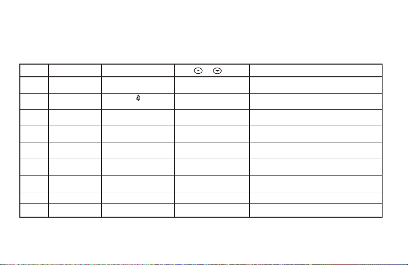
Press RUN to make sure the thermostat is in the run program mode, then press PRGM and RUN at the same time
to enter the conguration menu. The display will show the rst item in the conguration menu.
The conguration menu table summarizes the conguration options. An explanation of each option follows.
Press HOLD to change to the next menu item or press TIME to go backwards to the previous item in the menu. To
exit the menu and return to the program operation, press RUN. If no keys are pressed within fteen minutes, the
thermostat will revert to normal operation.
1. Select Temporary Hold Time – The thermostat can hold any temperature you set it to for the amount of time
you select on this option. Your choices are 0:00 to 8:00 hours in 15 minute increments. 0:00 disables the func-
tion
Example:
1. You have selected 3:00 hours for the Temporary Hold time period.
2. With the thermostat set to Heat or Cool, press HOLD for approximately ve seconds until HOLD time (3:00
indicating 3 hours) appears as a setting reminder.

21
3. After releasing the button, “HOLD” on the display will blink.
4. Use or to set the temperature to your preference. The thermostat will maintain this temperature setting
for 3 hours with “HOLD” blinking to remind you it is in Temporary Hold. After 3 hours the thermostat will go
back to the program temperature and “HOLD” will no longer blink or display.
2. Select FA or SL (Fast or Slow) Heating Cycle Rate – The FA setting is frequently used for gas, oil or electric
heat. The SL setting produces a longer heating cycle which is normally for hot water or steam (hydronic) sys-
tems. Both settings produce very accurate temperature control and can be set to your personal preference. FA
cycles the system just under 1°F and the SL setting cycles at approximately 1.5°F.
3. Select backlit display – The display backlight improves display contrast in low lighting conditions. Selecting
backlight ON will keep the light on for a short period of time after any key is pressed. Selecting OFF will keep the
light off.
4. Select Energy Management Recovery OFF or ON – Energy Management Recovery (EMR) causes the
thermostat to start heating or cooling early to make the building temperature reach the program setpoint at the
time you specify. Heating will start 5 minutes early for every 1° of temperature required to reach setpoint.
Example:
You select EMR and have your heating programmed to 65° at night and 70° at 7 AM. If the building temperature
is 65° the difference between 65° and 70° is 5°. Allowing 5 minutes per degree the thermostat setpoint will
change to 70° at 6:35 AM. Cooling allows more time per degree because it takes longer to reach temperature.

22
5. Select lter replacement run time – The thermostat will display “FLTR” after a set time of operation. This is a
reminder to change or clean your air lter. This time can be set from 0 to 1950 hours in 50 hour increments. A
selection of 000 will cancel this feature. When “FLTR” is displayed, you can clear it by pressing HOLD and
RUN at the same time. This resets the timer and starts counting the hours until the next lter change. Changing
the time in the menu also resets the timer.
6. Select Compressor Lockout LOC OFF or ON – Selecting LOC ON will cause the thermostat to wait 5
minutes before turning on the compressor if the heating and cooling system loses power. It will also wait a
minimum of 5 minutes between cooling cycles. This is intended to help protect the compressor from short
cycling. Some newer compressors already have a time delay built in and do not require this feature. Your
compressor manufacturer can tell you if the feature is already present in their system. When the compressor
time delay occurs it will flash the (snowflake icon) for about ve minutes then turn on the compressor.
7. Select Temperature Display Adjustment 4 LO to 4 HI – Allows you to adjust the room temperature display
+/- 4°. Your thermostat was accurately calibrated at the factory but you have the option to change the display
temperature to match your previous thermostat.
8. Select F° or C° Readout – Changes the display readout to Celsius or Fahrenheit as required.
23
5
4)4)
4)4)
4)
Select Energy Management Recovery OFF or ONSelect Energy Management Recovery OFF or ON
Select Energy Management Recovery OFF or ONSelect Energy Management Recovery OFF or ON
Select Energy Management Recovery OFF or ON -
Energy Management Recovery (EMR) causes the thermo-
stat to start heating or cooling early to make the building
temperature reach the program setpoint at the time you
specify. Heating will start 5 minutes early for every 1° of
temperature required to reach setpoint.
Example:Example:
Example:Example:
Example: You select EMR and have your heating pro-
grammed to 65° at night and 70° at 7 AM. If the building
temperature is 65° the difference between 65° and 70° is
5°. Allowing 5 minutes per degree the thermostat setpoint
will change to 70° at 6:35 AM. Cooling allows more time per
degree because it takes longer to reach temperature.
5)5)
5)5)
5)
Select filter replacement run timeSelect filter replacement run time
Select filter replacement run timeSelect filter replacement run time
Select filter replacement run time - The thermostat will
display
“FLTR”“FLTR”
“FLTR”“FLTR”
“FLTR” after a set time of operation. This is a
reminder to change or clean your air filter. This time can be
set from 0 to 1950 hours in 50 hour increments.
A selectionA selection
A selectionA selection
A selection
of 000 will cancel this feature.of 000 will cancel this feature.
of 000 will cancel this feature.of 000 will cancel this feature.
of 000 will cancel this feature. When
“FLTR”“FLTR”
“FLTR”“FLTR”
“FLTR” is displayed,
you can clear it by pressing HOLD and RUN at the same
time. This resets the timer and starts counting the hours
until the next filter change. Changing the time in the menu
also resets the timer.
6)6)
6)6)
6)
Select Compressor Lockout LOC OFF or ONSelect Compressor Lockout LOC OFF or ON
Select Compressor Lockout LOC OFF or ONSelect Compressor Lockout LOC OFF or ON
Select Compressor Lockout LOC OFF or ON - Selecting
LOC ON will cause the thermostat to wait 5 minutes before
turning on the compressor if the heating and cooling sys-
tem loses power. It will also wait 5 minutes minimum
between cooling cycles. This is intended to help protect the
compressor from short cycling. Some newer compressors
already have a time delay built in and do not require this
feature. Your compressor manufacturer can tell you if the
feature is already present in their system. When the com-
pressor time delay occurs it will flash the (snowflake icon)
for about five minutes then turn on the compressor.
7)7)
7)7)
7)
Select Temperature Display Adjustment 4 LO to 4 HISelect Temperature Display Adjustment 4 LO to 4 HI
Select Temperature Display Adjustment 4 LO to 4 HISelect Temperature Display Adjustment 4 LO to 4 HI
Select Temperature Display Adjustment 4 LO to 4 HI -
Allows you to adjust the room temperature display 4° higher
or lower. Your thermostat was accurately calibrated at the
factory but you have the option to change the display
temperature to match your previous thermostat.
8)8)
8)8)
8)
Select F° or C° ReadoutSelect F° or C° Readout
Select F° or C° ReadoutSelect F° or C° Readout
Select F° or C° Readout - Changes the display readout to
Centigrade or Fahrenheit as required.
OPERATING FEATURESOPERATING FEATURES
OPERATING FEATURESOPERATING FEATURES
OPERATING FEATURES
Now that you are familiar with the thermostat buttons and
display, read the following information to learn about the many
features of the thermostat.
•
SIMULTANEOUS HEATING/COOLING PROGRAMSIMULTANEOUS HEATING/COOLING PROGRAM
SIMULTANEOUS HEATING/COOLING PROGRAMSIMULTANEOUS HEATING/COOLING PROGRAM
SIMULTANEOUS HEATING/COOLING PROGRAM
STORAGESTORAGE
STORAGESTORAGE
STORAGE — When programming, you can enter both
your heating and cooling programs at the same time. There
is no need to reprogram the thermostat at the beginning of
each season.
•
TEMPERATURE OVERRIDETEMPERATURE OVERRIDE
TEMPERATURE OVERRIDETEMPERATURE OVERRIDE
TEMPERATURE OVERRIDE — Press
or until the
display shows the temperature you want. The thermostat
will override current programming and keep the room
temperature at the selected temperature until the next
program period begins. Then the thermostat will automati-
cally revert to the program.
•
HOLD TEMPERATUREHOLD TEMPERATURE
HOLD TEMPERATUREHOLD TEMPERATURE
HOLD TEMPERATURE — The thermostat can hold any
temperature within its range for an indefinite period without
reverting to the programmed temperature. Momentarily
press HOLD button.
“HOLD”“HOLD”
“HOLD”“HOLD”
“HOLD” will be displayed. Then choose
the desired temperature by pressing
or . The
thermostat will hold the room temperature at the selected
setting until you press RUN button to start program opera-
tion again.
•
CONFIGURATION MENUCONFIGURATION MENU
CONFIGURATION MENUCONFIGURATION MENU
CONFIGURATION MENU — Allows you to customize
certain thermostat options.
PROGRAMMING YOUR THERMOSTATPROGRAMMING YOUR THERMOSTAT
PROGRAMMING YOUR THERMOSTATPROGRAMMING YOUR THERMOSTAT
PROGRAMMING YOUR THERMOSTAT
This section will help you plan your thermostat’s program to
meet your needs. For maximum comfort and efficiency, keep
the following guidelines in mind when planning your program.
• When heating (cooling) your building, program the
temperatures to be cooler (warmer) when the building is
vacant or during periods of low activity.
• During early morning hours, the need for cooling is
usually minimal.
1
Step Press Button(s) Displayed (Factory Default) Press or to select: COMMENTS
HOLD
(0:00)
0 to 8 hrs (in
15 minute increments)
2
(FA)
SL
Select temporary Hold time
4
5
E
(ON)
OFF
6
7
LOC
(OFF)
ON
0 HI
(0)
4 LO to
4 HI
(F) C
Returns to normal operation
8
9
Select Energy Management Recovery OFF or ON
Select compressor lockout OFF or ON
Select temperature display adjustment higher or lower
Select temperature display to F or C
RUN
PRGM
and RUN
HOLD
*
HOLD
*
3
d-L
(ON)
OFF
Select display backlight OFF or ON
HOLD
*
HOLD
*
Filter
(000)
0 to 1950 hours
(in 50 hour increments)
Select filter replacement run time
HOLD
*
HOLD
*
HOLD
*
Select FA or SL (Fast or Slow) heating cycle rate
Configuration Menu
* Press
HOLD to advance to next item or TIME to move backwards to previous item

24
6.4 Operating features
This section contains information about the many features of your new thermostat.
• SIMULTANEOUS HEATING/COOLING PROGRAM STORAGE — When programming, you can enter both your
heating and cooling programs at the same time. There is no need to reprogram the thermostat at the beginning
of each season.
• TEMPERATURE OVERRIDE — Press or until the display shows your desired temperature.
The thermostat will override current programming and keep the room temperature at the selected temperature
until the next program period begins; then, the thermostat will automatically revert to the program.
• HOLD TEMPERATURE — The thermostat can hold any temperature within its range for an indenite period
without reverting to the programmed temperature. To engage this feature, press HOLD button. “HOLD” will be
displayed. Then choose the desired temperature by pressing or . The thermostat will hold the room
temperature at the selected setting until you press RUN button to start program operation again.
• CONFIGURATION MENU — Allows you to customize certain thermostat options.

25
6.5 Programming your thermostat
This section will help you plan your thermostat’s program to meet your needs. For maximum comfort and efciency,
keep the following guidelines in mind when planning your program:
• When heating (cooling) your building, program the temperatures to be cooler (warmer) when the building is
vacant or during periods of low activity.
• During early morning hours, the need for cooling is usually minimal.
Planning your program
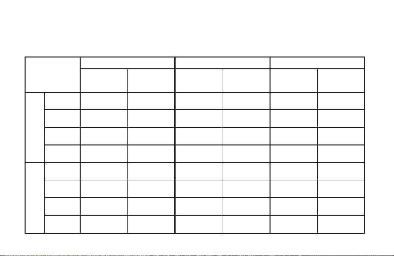
Look at the factory pre-programmed times and temperatures shown in the sample schedule. If this program will suit
your needs, simply press the RUN button to begin running the factory preset program.
If you want to change the pre-programmed times and temperatures, follow these steps.
Determine the time periods and temperatures for your weekday and weekend programs. You must program
four periods for both the weekday and weekend program. However, you may use the same heating and cooling
temperatures for consecutive time periods. You can choose start times, heating temperatures, and cooling
temperatures independently for both weekday and weekend programs (for example, you may select 5:00 AM and
70° as the weekday 1st period heating start time and temperature, and also choose 7:00 AM and 76° as the
weekday 1st period cooling start time and temperature).
26
6
Enter Heating ProgramEnter Heating Program
Enter Heating ProgramEnter Heating Program
Enter Heating Program
1. Move the SYSTEM switch to
HEATHEAT
HEATHEAT
HEAT.
2. Press PRGM once. “
MO TU WE TH FRMO TU WE TH FR
MO TU WE TH FRMO TU WE TH FR
MO TU WE TH FR” (indicating week-
day program) will appear in the display. Also displayed are
the currently programmed start time for the
1st heating1st heating
1st heating1st heating
1st heating
period and the currently programmed temperature (flash-
ing).
EXAMPLE:
AM
MO TU WE TH FR
This display window shows that for the 1st weekday period,
the start time is 6:00 AM, and 68° is the programmed
temperature (this example reflects factory preprogramming).
3. Press or to change the displayed temperature to
your selected temperature for the 1st heating program
period.
4. Press TIME once (the programmed time will flash). Press
or until your selected time appears. The time will
change in 15 minute increments. When your selected time
is displayed, press TIME again to return to the change
temperature mode.
5. Press PRGM once. The currently programmed start time
and setpoint temperature for the
2nd heating2nd heating
2nd heating2nd heating
2nd heating program
period will appear.
6. Repeat steps 3 and 4 to select the start time and heating
temperature for the 2nd heating program period.
7. Repeat steps 3 through 5 for the 3rd and 4th heating
program periods. Weekday heating programs are now com-
plete.
8. Press PRGM once. “
SASA
SASA
SA” (indicating Saturday program) will
appear in the display, along with the start time for the 1st
heating period and the currently programmed temperature.
9. Repeat steps 3 through 7 to complete Saturday heating
programming.
10.Press PRGM once. “
SUSU
SUSU
SU” (indicating Sunday program) will
appear in the display, along with the start time for the 1st
heating period and the currently programmed temperature.
11.Repeat steps 3 through 7 to complete Sunday heating
programming.
12.When you have completed entering your heating program,
press RUN.
Planning Your ProgramPlanning Your Program
Planning Your ProgramPlanning Your Program
Planning Your Program
Look at the factory preprogrammed times and temperatures
shown in the sample schedule. If this program will suit your
needs, simply press the RUN button to begin running the factory
preset program.
If you want to change the preprogrammed times and tempera-
tures, follow these steps.
Determine the time periods and temperatures for your weekday
and weekend programs. You must program four periods for
both the weekday and weekend program. However, you may
use the same heating and cooling temperatures for consecutive
time periods. You can choose start times, heating tempera-
tures, and cooling temperatures independently for both week-
day and weekend programs (for example, you may select 5:00
AM and 70° as the weekday
1st period heating1st period heating
1st period heating1st period heating
1st period heating start time and
temperature, and also choose 7:00 AM and 76° as the weekday
1st period cooling1st period cooling
1st period cooling1st period cooling
1st period cooling start time and temperature).
Use the following table to plan your program time periods and
the temperatures you want during each period. Fill in the
complete table to have a record of your programs.
Entering Your ProgramEntering Your Program
Entering Your ProgramEntering Your Program
Entering Your Program
Follow these steps to enter the heating and cooling programs
you have selected.
Set Current Time and DaySet Current Time and Day
Set Current Time and DaySet Current Time and Day
Set Current Time and Day
1. Press TIME button once. The display will show the hour only.
EXAMPLE:
PM
2. Press and hold either or until you reach the correct
hour and AM/PM designation (
AMAM
AMAM
AM begins at midnight;
PMPM
PMPM
PM
begins at noon).
3. Press TIME once. The display window will show the minutes
only.
EXAMPLE:
4. Press and hold either or until you reach the correct
minutes.
5. Press TIME once. The display will show the day of the week.
6. Press
or until you reach the current day of the week.
7. Press RUN once. The display will show the correct time and
room temperature alternately.
WEEKDAY (5 DAY)
SATURDAY (1 DAY)
Start
Time Temperature
Start
Time Temperature
1ST 6:00 AM 70°F 6:00 AM 70°F 6:00 AM 70°F
2ND 8:00 AM 62°F 8:00 AM 62°F 8:00 AM 62°F
3RD 5:00 PM 70°F 5:00 PM 70°F 5:00 PM 70°F
4TH 10:00 PM 62°F 10:00 PM 62°F 10:00 PM 62°F
1ST 6:00 AM 78°F 6:00 AM 78°F 6:00 AM 78°F
2ND 8:00 AM 85°F 8:00 AM 85°F 8:00 AM 85°F
3RD 5:00 PM 78°F 5:00 PM 78°F 5:00 PM 78°F
4TH 10:00 PM 82°F 10:00 PM 82°F 10:00 PM 82°F
SAMPLE
Heating/Cooling Schedule Plan (Factory Program)
Period
SUNDAY (1 DAY)
Start
Time Temperature
COOL HEAT
WEEKDAY (5 DAY)
SATURDAY (1 DAY)
Start
Time Temperature
Start
Time Temperature
1ST
2ND
3RD
4TH
1ST
2ND
3RD
4TH
Heating/Cooling Schedule Plan
Period
SUNDAY (1 DAY)
Start
Time Temperature
COOL HEAT
27
6
Enter Heating ProgramEnter Heating Program
Enter Heating ProgramEnter Heating Program
Enter Heating Program
1. Move the SYSTEM switch to
HEATHEAT
HEATHEAT
HEAT.
2. Press PRGM once. “
MO TU WE TH FRMO TU WE TH FR
MO TU WE TH FRMO TU WE TH FR
MO TU WE TH FR” (indicating week-
day program) will appear in the display. Also displayed are
the currently programmed start time for the
1st heating1st heating
1st heating1st heating
1st heating
period and the currently programmed temperature (flash-
ing).
EXAMPLE:
AM
MO TU WE TH FR
This display window shows that for the 1st weekday period,
the start time is 6:00 AM, and 68° is the programmed
temperature (this example reflects factory preprogramming).
3. Press
or to change the displayed temperature to
your selected temperature for the 1st heating program
period.
4. Press TIME once (the programmed time will flash). Press
or until your selected time appears. The time will
change in 15 minute increments. When your selected time
is displayed, press TIME again to return to the change
temperature mode.
5. Press PRGM once. The currently programmed start time
and setpoint temperature for the
2nd heating2nd heating
2nd heating2nd heating
2nd heating program
period will appear.
6. Repeat steps 3 and 4 to select the start time and heating
temperature for the 2nd heating program period.
7. Repeat steps 3 through 5 for the 3rd and 4th heating
program periods. Weekday heating programs are now com-
plete.
8. Press PRGM once. “
SASA
SASA
SA” (indicating Saturday program) will
appear in the display, along with the start time for the 1st
heating period and the currently programmed temperature.
9. Repeat steps 3 through 7 to complete Saturday heating
programming.
10.Press PRGM once. “
SUSU
SUSU
SU” (indicating Sunday program) will
appear in the display, along with the start time for the 1st
heating period and the currently programmed temperature.
11.Repeat steps 3 through 7 to complete Sunday heating
programming.
12.When you have completed entering your heating program,
press RUN.
Planning Your ProgramPlanning Your Program
Planning Your ProgramPlanning Your Program
Planning Your Program
Look at the factory preprogrammed times and temperatures
shown in the sample schedule. If this program will suit your
needs, simply press the RUN button to begin running the factory
preset program.
If you want to change the preprogrammed times and tempera-
tures, follow these steps.
Determine the time periods and temperatures for your weekday
and weekend programs. You must program four periods for
both the weekday and weekend program. However, you may
use the same heating and cooling temperatures for consecutive
time periods. You can choose start times, heating tempera-
tures, and cooling temperatures independently for both week-
day and weekend programs (for example, you may select 5:00
AM and 70° as the weekday
1st period heating1st period heating
1st period heating1st period heating
1st period heating start time and
temperature, and also choose 7:00 AM and 76° as the weekday
1st period cooling1st period cooling
1st period cooling1st period cooling
1st period cooling start time and temperature).
Use the following table to plan your program time periods and
the temperatures you want during each period. Fill in the
complete table to have a record of your programs.
Entering Your ProgramEntering Your Program
Entering Your ProgramEntering Your Program
Entering Your Program
Follow these steps to enter the heating and cooling programs
you have selected.
Set Current Time and DaySet Current Time and Day
Set Current Time and DaySet Current Time and Day
Set Current Time and Day
1. Press TIME button once. The display will show the hour only.
EXAMPLE:
PM
2. Press and hold either or until you reach the correct
hour and AM/PM designation (
AMAM
AMAM
AM begins at midnight;
PMPM
PMPM
PM
begins at noon).
3. Press TIME once. The display window will show the minutes
only.
EXAMPLE:
4. Press and hold either or until you reach the correct
minutes.
5. Press TIME once. The display will show the day of the week.
6. Press
or until you reach the current day of the week.
7. Press RUN once. The display will show the correct time and
room temperature alternately.
WEEKDAY (5 DAY)
SATURDAY (1 DAY)
Start
Time Temperature
Start
Time Temperature
1ST 6:00 AM 70°F 6:00 AM 70°F 6:00 AM 70°F
2ND 8:00 AM 62°F 8:00 AM 62°F 8:00 AM 62°F
3RD 5:00 PM 70°F 5:00 PM 70°F 5:00 PM 70°F
4TH 10:00 PM 62°F 10:00 PM 62°F 10:00 PM 62°F
1ST 6:00 AM 78°F 6:00 AM 78°F 6:00 AM 78°F
2ND 8:00 AM 85°F 8:00 AM 85°F 8:00 AM 85°F
3RD 5:00 PM 78°F 5:00 PM 78°F 5:00 PM 78°F
4TH 10:00 PM 82°F 10:00 PM 82°F 10:00 PM 82°F
SAMPLE
Heating/Cooling Schedule Plan (Factory Program)
Period
SUNDAY (1 DAY)
Start
Time Temperature
COOL HEAT
WEEKDAY (5 DAY)
SATURDAY (1 DAY)
Start
Time Temperature
Start
Time Temperature
1ST
2ND
3RD
4TH
1ST
2ND
3RD
4TH
Heating/Cooling Schedule Plan
Period
SUNDAY (1 DAY)
Start
Time Temperature
COOL HEAT
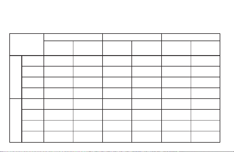
Use the following table to plan your program time periods and the temperatures you want during each period.
Fill in the complete table to have a record of your programs.
28
Entering your program
Follow these steps to enter the heating and cooling programs you have selected.
Set Current Time and Day
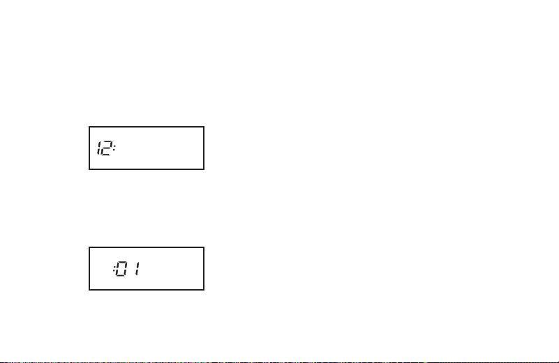
1. Press TIME button once. The display will show the hour only.
EXAMPLE:
PM
2. Press and hold either or until you reach the correct hour and AM/PM designation
(AM begins at midnight; PM begins at noon).
3. Press TIME once. The display window will show the minutes only.
EXAMPLE:
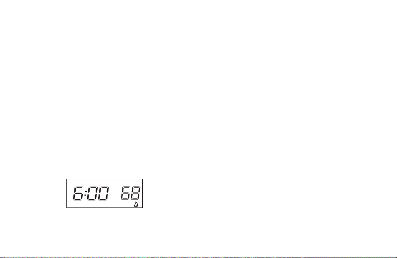
29
4. Press and hold either or until you reach the correct minutes.
5. Press TIME once. The display will show the day of the week.
6. Press or until you reach the current day of the week.
7. Press RUN once. The display will show the correct time and room temperature alternately.
Set Heating Program
1. Move the SYSTEM switch to HEAT.
2. Press PRGM once. “MO TU W TH FR” (indicating weekday program) will appear in the display. Also displayed
are the currently programmed start time for the 1st heating period and the currently programmed temperature
(flashing).
EXAMPLE:
AM
MO TU WE TH FR
This display window shows that for the 1st weekday period, the start time is 6:00 AM, and 68° is the
programmed temperature (this example reflects factory preprogramming).

30
3. Press or to change the displayed temperature to your selected temperature for the 1st heating program
period.
4. Press TIME once (the programmed time will flash). Press or until your desired time appears. The time
will change in 15 minute increments. When your selected time is displayed, press TIME again to return to the
change temperature mode.
5. Press PRGM once. The currently programmed start time and setpoint temperature for the 2nd heating program
period will appear.
6. Repeat steps 3 and 4 to select the start time and heating temperature for the 2nd heating program period.
7. Repeat steps 3 through 5 for the 3rd and 4th heating program periods. Weekday heating programs are now
complete.
8. Press PRGM once. “SA” (indicating Saturday program) will appear in the display, along with the start time for
the 1st heating period and the currently programmed temperature.
9. Repeat steps 3 through 7 to complete Saturday heating programming.
10. Press PRGM once. “SU” (indicating Sunday program) will appear in the display, along with the start time for the
1st heating period and the currently programmed temperature.
11. Repeat steps 3 through 7 to complete Sunday heating programming.
31
12. When you have completed entering your heating program, press RUN.
1. Move SYSTEM switch to COOL position.
2. To set your cooling program, follow the same procedure as setting your heating program, but use your selected
cooling times and temperatures.
If the outside temperature is below 50° F, disconnect power to the cooling system before programming. Energizing the air conditioner
compressor during cold weather may cause personal injury or property damage.
CAUTION
!
Set Cooling Program

32
Check your programming
Follow these steps to check your thermostat programming one nal time before beginning thermostat operation.
1. Move SYSTEM switch to HEAT position.
2. Press PRGM to view the 1st weekday heating period time and temperature. Each time you press PRGM, the
next heating period time and temperature will be displayed in sequence for weekday, then weekend program
periods (you may change any time or temperature during this procedure).
3. Press RUN.
4. Move SYSTEM switch to COOL position.
5. Repeat step 2 to check cooling program.
6. Move SYSTEM switch to HEAT or COOL and press RUN to begin program operation.
CONGRATULATIONS! Your new thermostat is now programmed.

33
7. SPECIFICATIONS
ELECTRICAL DATA
Electrical Rating:
8 to 30 VAC 50/60 Hz. or D.C.
0.05 to 1.0 Amps (Load per terminal)
1.5 Amps Maximum Total Load (All terminals combined)
THERMAL DATA
Setpoint Temperature Range: 45°F to 90°F (7°C to 32°C)
Operating Ambient Temperature Range: 32°F to 105°F
Operating Humidity Range: 0 to 90% RH (non-condensing)
Shipping Temperature Range: -4°F to 149°F

34
APPLICATIONS
For use with:
• Standard heat/cool or heat only systems
• Electric heat systems
• Gas or oil red systems
• Gas systems with intermittent ignition devices (I.I.D.) and/or vent dampers
• Hydronic (hot water or steam) systems
• Single-stage heat pump systems (no auxiliary heat)
• Millivolt
DO NOT USE WITH:
• Multi-stage systems
• Systems exceeding 30 VAC and 1.5 amps
• 3-wire zoned hydronic heating systems

35
8. TROUBLESHOOTING
Reset Operation
If a voltage spike or static discharge blanks out the display or causes erratic thermostat operation you can reset the
thermostat by pressing , , and TIME at the same time. This also resets the factory defaults to the congura-
tion menu and program. If the thermostat has power, has been reset and still does not function correctly contact your
heating/cooling ser-vice person or place of purchase.
Batteries
For optimum performance, we recommend replacing batteries once a year with fresh "AAA" alkaline batteries.
36
Symptom Possible Cause Corrective Action
No Heat/No Cool/No Fan
(common problems)
1. Blown fuse or tripped circuit breaker.
2. Furnace power switch to OFF.
3. Furnace blower compartment door or
panel loose or not properly installed.
Replace fuse or reset breaker.
Turn switch to ON.
Replace door panel in proper position to
engage safety interlock or door switch.
No Cool 1. SYSTEM Switch not set to Cool.
2. Loose connection to thermostat or
system.
3. Cooling system requires service or
thermostat requires replacement.
Set SYSTEM Switch to COOL and
lower setpoint temperature below room
temperature.
Verify thermostat and system wires are
securely attached.
Same procedure as diagnostic for No
Heat condition except set the thermostat
to COOL and lower the setpoint below
the room temperature. There may be
up to a ve minute delay before the
thermostat clicks in Cooling.
37
Symptom Possible Cause Corrective Action
No Heat 1. Pilot light not lit.
2. SYSTEM Switch not set to HEAT.
3. Loose connection to thermostat
or system.
4. Furnace Lock-Out Condition.
Heat may also be intermittent.
5. Heating system requires
service or thermostat requires
replacement..
Re-light pilot.
Set SYSTEM Switch to HEAT and raise setpoint temperature
above room temperature.
Verify thermostat and system wires are securely attached.
Many furnaces have safety devices that shutdown when a
lock-out condition occurs. If the heat works intermittently
contact the furnace manufacturer or local service person for
assistance.
Diagnostic: Set SYSTEM Switch to HEAT and raise the
setpoint above room temperature. Within a few seconds
the thermostat should make a soft click sound. This sound
usually indicates the thermostat is operating properly. If the
thermostat does not click, try the reset operation listed below.
If the thermostat does not click after being reset contact your
heating and cooling service person or place of purchase for
a replacement. If the thermostat clicks, contact the furnace
manufacturer or a service person to verify the heating is
operating correctly.
38
Symptom Possible Cause Corrective Action
Heat, Cool or Fan Runs Constantly. 1. FAN Switch set to Fan ON.
2. Possible short in wiring.
3. Possible short in thermostat.
4. Possible short in Heat/Cool/Fan
system.
Check each wire connection to
verify they are not shorted or touching
together. No bare wire should stick
out from under terminal screws. Try
resetting the thermostat. If the condition
persists the manufacturer of your sys-
tem or service person can instruct you
on how to test the Heat/Cool system for
correct operation. If the system operates
correctly, replace the thermostat.
Furnace Cycles Too Fast or
Too Slow
(narrow or wide temperature swing)
1. The location of the thermostat and/or
the size of the Heating System may
be influencing the cycle rate.
Item 2 in the Conguration Menu is the
adjustment that controls the cycle rate. If
an acceptable cycle rate is not achieved
using the FA (Fast) or SL (Slow) adjust-
ment contact a local service person for
additional suggestions.
39
Symptom Possible Cause Corrective Action
Cooling Cycles Too Fast or Too Slow
(narrow or wide temperature swing)
1. The location of the thermostat and/or
the size of the Cooling System may
be influencing the cycle rate.
The cycle rate for cooling is xed and
can not be adjusted. Contact a local
service person for suggestions.
Thermostat Setting and
Thermometer Disagree
1. Thermostat thermometer setting
requires adjustment.
The thermometer can be adjusted +/- 4
degrees as listed in item 7 of the Con-
guration Menu. No other adjustment
is possible.
Clock Loses or Gains Time 1. Loss of power to thermostat and low
batteries.
The thermostat will maintain its program
in memory even with no power/no
batteries but the clock time will be
incorrect when power is restored. See
No Heat/No Cool/No Fan (common
problems) above for items to check in
the system.
Heat or Cool Starts Early 1. EMR activated See Conguration Menu (Item 4).
40
Symptom Possible Cause Corrective Action
Thermostat Does Not Follow Program 1. AM or PM set incorrectly in program.
2. AM or PM set incorrectly on the clock.
3. Voltage spike or static discharge.
Check current clock and program
settings including the AM or PM desig-
nations for each time period. If a voltage
spike or static discharge occurs use the
Reset Operation listed above.
Blank Display and/or Keypad
Not Responding
1. Loss of power and dead batteries.
2. Voltage Spike or Static Discharge.
Replace batteries and check heat/cool
system for proper operation. If a voltage
spike or static discharge occurs use the
Reset Operation listed above.


42

43
MERCURY NOTICE
This product does not contain mercury. However, this product may replace a product
that contains mercury.
Mercury and products containing mercury must not be discarded in household trash.
Refer to thermostat-recycle.org for location to send product containing mercury.
FOR CALIFORNIA RESIDENTS
Warning: This product contains a chemical known to the state of California to cause
cancer and birth defects and other reproductive harm.

44