Model # UNP310
Made in China
Universal Thermostat
37-7580A
Install Guide
Want to install the easy way?
2
GUIDE CONTENTS
Preparations ........................................................................ 3
Thermostat details ............................................................... 5
Removal of your old thermostat........................................... 7
Mounting, wiring, and conguring your new thermostat .... 11
Checking thermostat operation.......................................... 18
Using your thermostat ....................................................... 20
Specications .................................................................... 26
Troubleshooting ................................................................. 27
Failure to follow and read all instructions carefully before installing or operating this control could cause personal injury
and/or property damage.

3
1. PREPARATIONS
Precautions
• Donotexceedthespecicationratings.
• All wiring must conform to local and national electrical codes and ordinances.
4
1.1 Check package contents
This package should contain the following items:
• Thermostat
• Mounting screws and wall anchors (x2)
• 2 AA batteries
• Terminal wire label stickers
• Installation instructions
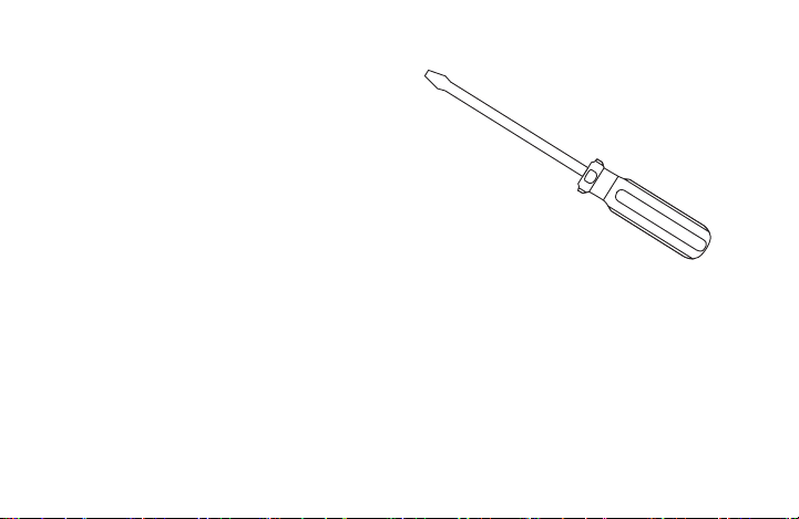
1.2 Gather tools
Required:
□SmallPhillipsorFlat-headscrewdriver□Smallpliers(needle-nose)□Drillwith3/16”(4mm)bit
Optional:
□Wirecutters/stripper□Hammer(forwallanchors)
5
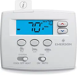
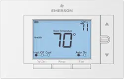
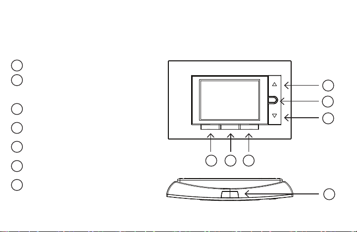
2. THERMOSTAT DETAILS
The thermostat buttons and switches
Fan button
Away button (set a frequntly used
temperature)
Systembutton
Backlight button
Raises temperature setting
Access menu options
Lowers temperature setting
1
2
3
4
5
6
7
8
9
10
11
12
13
14
15
16
17
18
19
20
1
2
3
4
5
6
7
8
9
10
11
12
13
14
15
16
17
18
19
20
1
2
3
4
5
6
7
8
9
10
11
12
13
14
15
16
17
18
19
20
1
2
3
4
5
6
7
8
9
10
11
12
13
14
15
16
17
18
19
20
1
2
3
4
5
6
7
8
9
10
11
12
13
14
15
16
17
18
19
20
1
2
3
4
5
6
7
8
9
10
11
12
13
14
15
16
17
18
19
20
1
2
3
4
5
6
7
8
9
10
11
12
13
14
15
16
17
18
19
20
1
2
3
4
5
6
7
8
9
10
11
12
13
14
15
16
17
18
19
20
1
2
3
4
5
6
7
8
9
10
11
12
13
14
15
16
17
18
19
20
1
2
3
4
5
6
7
8
9
10
11
12
13
14
15
16
17
18
19
20
1
2
3
4
5
6
7
8
9
10
11
12
13
14
15
16
17
18
19
20
1
2
3
4
5
6
7
8
9
10
11
12
13
14
15
16
17
18
19
20
1
2
3
4
5
6
7
8
9
10
11
12
13
14
15
16
17
18
19
20
1
2
3
4
5
6
7
8
9
10
11
12
13
14
15
16
17
18
19
20
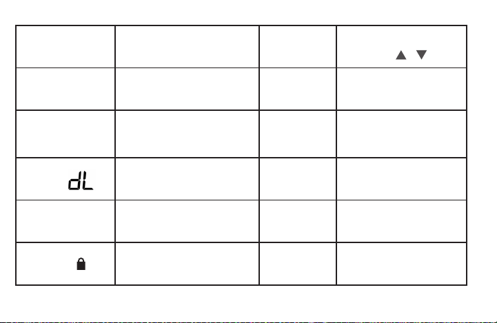
Menu
FanAwaySystem
6
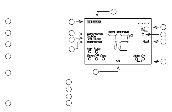
Next (Menu button) is used to
navigatewithinamenu
Back (Fan button) is used to
navigatewithinamenu
Exit (Away button) returns to the
home screen
Thermostat is protecting the
equipment from short cycling
(5-minutedelay)
Indicates that the system is running
inCool,HeatorAuxiliarymode.
(HeatPumpOnly-Theauxiliary
willruninHeatmodewhenthe
heat pump cannot maintain the set
temperature.)
SEE TROUBLESHOOTING
Battery status indicator
Replace battery indicator
Temperature setpoint
Appearswhenthekeypadislocked(topreventunwantedchanges)
1
2
3
4
5
6
7
8
9
10
11
12
13
14
15
16
17
18
19
20
1
2
3
4
5
6
7
8
9
10
11
12
13
14
15
16
17
18
19
20
1
2
3
4
5
6
7
8
9
10
11
12
13
14
15
16
17
18
19
20
1
2
3
4
5
6
7
8
9
10
11
12
13
14
15
16
17
18
19
20
1
2
3
4
5
6
7
8
9
10
11
12
13
14
15
16
17
18
19
20
1
2
3
4
5
6
7
8
9
10
11
12
13
14
15
16
17
18
19
20
1
2
3
4
5
6
7
8
9
10
11
12
13
14
15
16
17
18
19
20
The display
1
2
3
4
5
6
7
8
9
10
11
12
13
14
15
16
17
18
19
20
1
2
3
4
5
6
7
8
9
10
11
12
13
14
15
16
17
18
19
20
1
2
3
4
5
6
7
8
9
10
11
12
13
14
15
16
17
18
19
20
1
2
3
4
5
6
7
8
9
10
11
12
13
14
15
16
17
18
19
20
1
2
3
4
5
6
7
8
9
10
11
12
13
14
15
16
17
18
19
20
1
2
3
4
5
6
7
8
9
10
11
12
13
14
15
16
17
18
19
20
1
2
3
4
5
6
7
8
9
10
11
12
13
14
15
16
17
18
19
20
1
2
3
4
5
6
7
8
9
10
11
12
13
14
15
16
17
18
19
20
1
2
3
4
5
6
7
8
9
10
11
12
13
14
15
16
17
18
19
20
1
2
3
4
5
6
7
8
9
10
11
12
13
14
15
16
17
18
19
20
1
2
3
4
5
6
7
8
9
10
11
12
13
14
15
16
17
18
19
20
1
2
3
4
5
6
7
8
9
10
11
12
13
14
15
16
17
18
19
20
1
2
3
4
5
6
7
8
9
10
11
12
13
14
15
16
17
18
19
20
7
3. REMOVING OLD THERMOSTAT
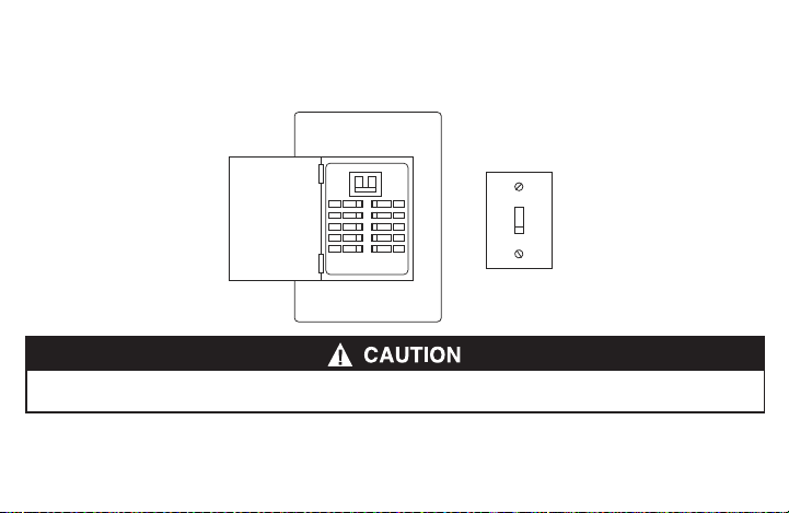
3.1 Turn off power
To ensure the power to your heating and cooling system has been turned off, try to turn on heating or cooling by
changing the temperature on your old thermostat.
or
Topreventelectricalshockand/orequipmentdamage,disconnectelectricalpowertothesystematthemainfuseorcircuitbreakerbox,orby
ippingaswitchattheairhandler.Donotrestorepoweruntilinstallationiscomplete.
8
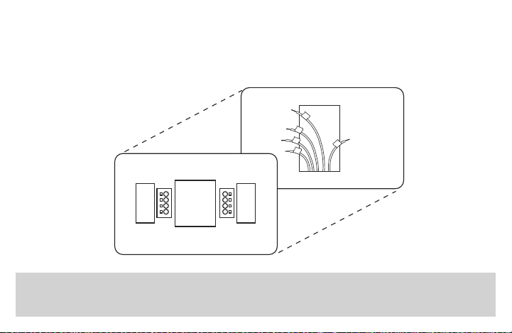
3.2 Remove the old thermostat cover
Removetheoldthermostat’sfrontcoverformthewallbase.Somecoverspulloffeasily,whileothersmayneedto
bereleasedbyusingascrewdriver.
3.3 Label wires
Tip: Taking a picture with a camera or smartphone can help you not only remember how wires are connected to the terminals, but can also ensure
that you label your wires correctly. Mislabeling the wires may result in a high energy bill or damage to your heating and cooling system.
Foreachwirethatcomesoutofwall,followthese4steps.
Note that this step is very important for conguring your system in section 4.5. Please follow
instruction carefully.
1.Locatetheterminalletterthatthewireisconnectedtointherstcolumnofthetable
2.Writedownthatoldthermostatterminalletterinthesecondcolumn
Youroldthermostatmayhaveasealedglasstubecontainingmercury.Becarefulnottodamagethetubeordisposeofthetubeinyourtrash.For
safedisposalinformation,pleaseseeMercuryNoticeonpage32
9
3.Labelthatwirewiththecorrespondingletterinthethirdcolumn
4.Disconnectthelabeledwirecarefully,andproceedtothenextwireuntilallwiresarelabeled
Pleasenotethatnotallterminalsmaybeusedandthatthere’snostandardcolorcodeforthermostatwires,soyour
wirecolorsmayvary.Foryourreference,we’veincludedaterminallabelreferencechartbelowtohelpyouconnect
the wires from your old thermostat to your new thermostat in case you get stuck.
Terminal labeling reference chart
If your current
terminal has the
following letter
Writedownthat
letter here
Label the wires with
the following letters
Terminal function
RH,R,R5,5 RH 24VPower(Heating)
RC RC 24VPower(Cooling)
C, X, B*
C
CommonWire
W,W1,W/E,
Aux/E,E
W/E
1stStageHeat(forconventionalsystem);1st
StageAuxiliaryHeat(forheatpumpsystem)
10
If your current
terminal has the
following letter
Writedown
that letter here
Label the wires with
the following letters
Terminal function
W2** W2
2ndStageHeat(Conventional)2ndStage
AuxiliaryHeat(HeatPump)
Y,Y1 Y 1stStageCompressor
Y2 Y2 2ndStagecompressor
G G Fan Relay
O, B*, O/B O/B ReversingValve(forheatpumpsystems)
L L HeatPumpDiagnostic
Terminal labeling reference chart, contʼd.
11
Do you have a “B” wire?
Labelingthe“B”wirecanbetricky.Itcouldbelabeledas“C”or“O/B”dependingonwhetheryouhavean“O”wire
connectedtoyouroldthermostat.Pleasepayattentionandfollowtheasterisk(*)commentsbelowwhilelabelingit.
*Label“B”as“C”onlyiftheoldthermostatalsohadawireinthe“O”terminalblock.Iftherewasnowireinthe“O”
terminalblock,labelthewireas“O/B”
**OnheatpumpsystemswithseparateW2andEwires,labelbothwiresW/E(2wiresononeterminal)
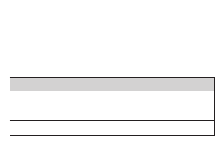
3.4 Identify jumper wire
ForterminalRCandRH:
On your old thermostat, if… Then, on your new thermostat…
TerminalRCandRHareconnected
with a jumper wire
LeavetheRC/RHjumperwireinitsplace
There’sonlyoneRwire(RC,RH,RorR5)
coming out of the wall
LeavetheRC/RHjumperwireinitsplace
Two separate R wires come out of the wall, and
they are NOT connected by a jumper wire
ClipthejumperwirebetweenRCandRHonthe
back of the new thermostat
12
EMERSON
50/60HZ OR DC 0.05 TO 1.5 AMP
(PER TERMINAL) 2.5 AMPS MAX.
(COMBINED LOAD) CLASS 2
0150-XXXXXX E1
XXXX 5001 9087 REV.X
UP MADE IN CHINA
RC/RH Jumper Wire
13
3.5 Remove old thermostat base
Withallofyourwiresdisconnectedandproperlylabeled,youmaynowsafelyremovethethermostatbasefrom
your wall.
Tip: Worriedabouthavingyourwiresfallingintoyourwall?Keepthewiressecurebywrappingthethem
around a pencil.
14
4. MOUNTING AND WIRING YOUR NEW THERMOSTAT
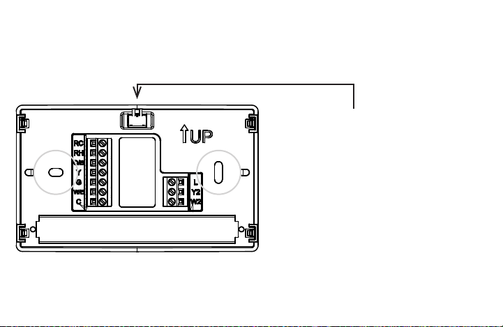
4.1 Install new thermostat base
Mount your new thermostat base using the supplied screws. Drill holes and insert wall anchors to secure the
thermostat base to the wall, if necessary.
Leveling Thermostat
Levelingisforappearanceonlyandwillnot
affect thermostat operation.
15
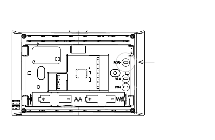
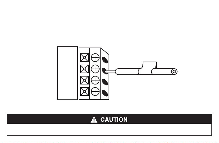
4.2 Connect wires to corresponding terminal blocks
Matcheachlabeledwiretoit’scorrespondingterminalonthemountedthermostatbase.Inserteachlabeledwireinto
theholeofit’smatchingterminal,andusingthescrewdriver,tightenthescrewontheterminalblocksecurely.
RC
RH
O/B
RH
Takecarewhensecuringandroutingwiressotheydonotshorttoadjacentterminalsorrearofthermostat.Personalinjuryand/orpropertydamage
may occur.
16
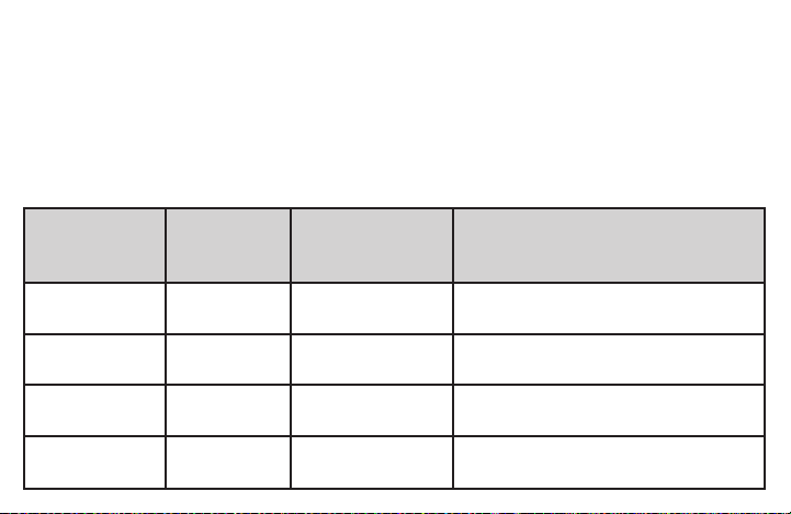
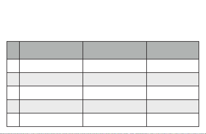
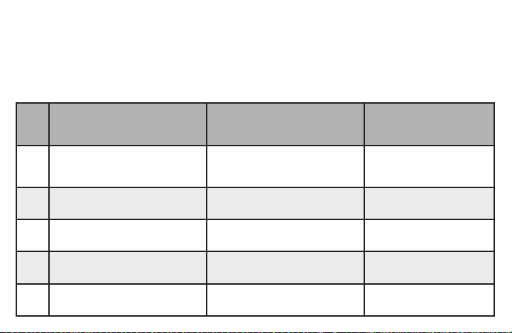
4.3 Identify system conguration
Your wiring can help to determine the type of heating and cooling equipment installed in your home. Before attaching
thefrontcover,usethefollowingchart,andchecktheboxnexttothesettingsthatmatchyournewthermostat’s
wiring. This information will be used in Step 4.5 to congure your thermostat.
Thermostat Terminals
with attached wires
Outdoor Equipment Setting (Used in 4.5)
▢
No wire on thermostat terminal Y No air conditioner / no heat pump AC0
▢
Y (no O/B) Single stage air conditioner AC1
▢
Y, Y2 (no O/B) Two stage air conditioner AC2
▢
Y, O/B Single stage heat pump HP1
▢
Y, Y2, O/B Two stage heat pump HP2
17
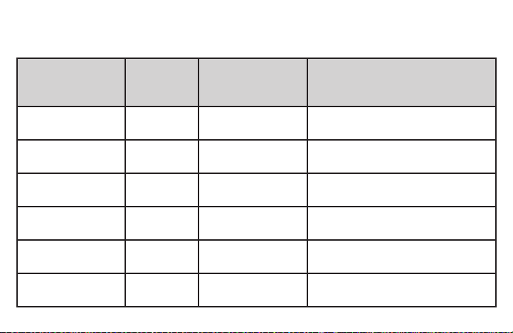
Thermostat Terminals
with attached wires
Indoor Equipment Setting (Used in 4.5)
▢
No wire on thermostat terminal W/E
Blower only (no indoor heating
equipment)
FAN
▢
W/E (Gas or Oil heat) Single stage gas or oil furnace GA1
▢
W/E, W2 (Gas or Oil heat) Two stage gas or oil furnace GA2
▢
W/E (Electric heat) Single stage electric furnace EL1
▢
W/E, W2 (Electric heat) Two stage electric furnace EL2
18
4.4 Install the batteries and attach front cover
InstalltheincludedAAalkalinebatteriesandpushthefrontcoverontothethermostatbaseuntilit’ssecure.
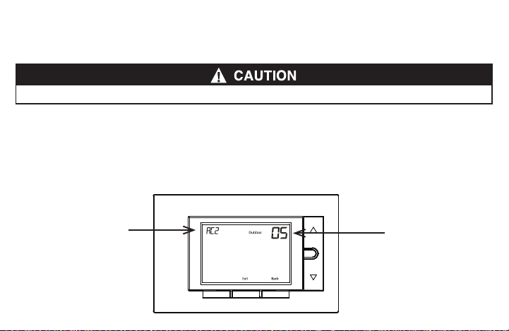
4.5 Congure thermostat
Holdthemenubuttondownfor8secondstolaunchtheinstallermenu.Yourscreenwillchangetotheconguration
menu.
Settherst3items(05,10,15)tomatchyourequipment.PleaserefertothetableinSection 4.3 and Section 3.3
tondoutyourequipmenttypeandoldwirings.
Do not restore power to the heating and cooling system until instructed.
Menu
FanAwaySystem
Menu
AC2: setting of the item
05: number of item on
installer menu
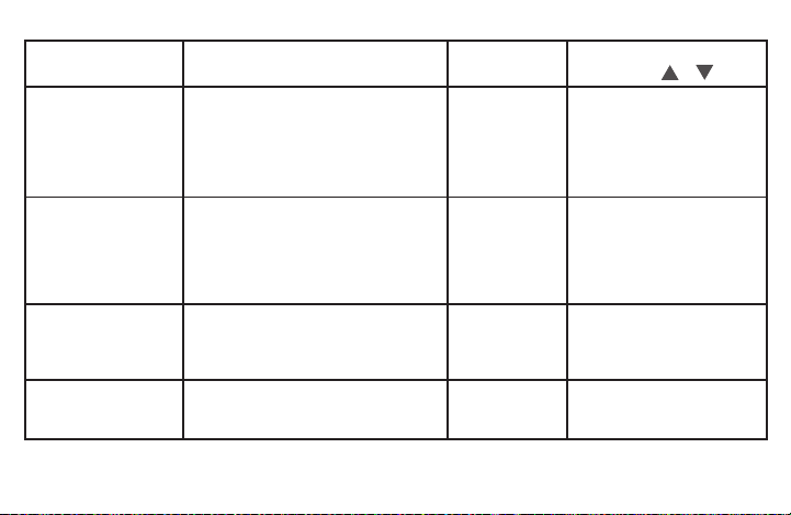
19
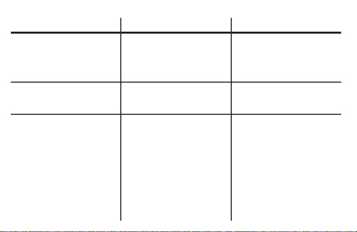
User Menu #
(Hold Menu 8 Seconds)
Description
Default Setting
(ashing icons)
Settings
(Press or )
05
Outdoor Equipment: selects air
conditioner (AC) or heat pump (HP)
equipment as well as the number of
stage
AC2
AC0
AC1
AC2
HP1
HP2
Refer to Section 4.3
10
Indoor Equipment: selects whether
the equipment is a gas furnace,
electric furnace or fan only
EL2
FAN
GA1
GA2
EL1
EL2
Refer to Section 4.3
20 R
Reversing valve set to O or B *
* For heat pump systems only
O
O if old thermostat has an O
terminal
B if old thermostat has a B
terminal
30 CR
Heat Cycle Rate: how often the heat
will turn on
MEd
SLO – slow
MEd – medium
FAS – fast
20
*Settingreversingvalveisnecessaryforheatpumpusersonly.Pleaserefertothechartinsection 3.3 for your old
thermostat’swiring.
On your OLD thermostat
•ifyouhadawireconnectedto“O”terminal,setreversingvalve(menu#20)valveas“O”atthisstep.
•ifyouhadawireconnectedto“B”terminal(andatthesametime,nowirewasconnectedto“O”),setreversing
valveas“B”atthisstep
•ifyouhadawireconnectedto“O/B”terminal,pleasecallCustomerSupportat877.654.9394.
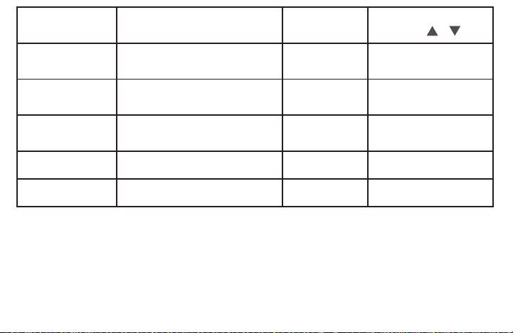
User Menu #
(Hold Menu 8 Seconds)
Description
Default Setting
(ashing icons)
Settings
(Press or )
32 CR
Aux Cycle Rate: how often the
auxiliary heat will turn on
MEd
SLO – slow
MEd – medium
FAS – fast
35 CR
Cool Cycle Rate: how often the
cooling will turn on
MEd
SLO – slow
MEd – medium
FAS – fast
50 CL
Compressor Lockout:
protects the compressor from short
cycling
OFF
On – 5 minute delay
OFF – no delay
65
Max Heat Limit: maximum set
point for heat mode
99 47 to 99
66
Minimum Cool Limit: minimum set
point for cool mode
45 45 to 97

21
4.6 Turn on power
Turn on your power at the source.
Congratulations!You’vecompletedthethermostatinstallationprocess.
5. CHECK THERMOSTAT OPERATION
5.1 Fan operation
If your system does nothaveaG terminal connection, skip to 5.2 Heating system.
1. PressthefanbuttontoselecttheOn position. The blower should operate.
2. PressthefanbuttontoselecttheAuto position. The blower should stop immediately.

22
5.2 Heating system
1. PresstheSystembuttontoselecttheHeatposition.
2. Press toadjustthermostatsettingto1°aboveroomtemperature.Theheatingsystemshouldbeginto
operate and the thermostat will indicate Heat On.
3. Forheatpumpwithauxiliary-Press toadjustthermostatsettingto3°aboveroomtemperature.Theauxiliary
heat should begin to operate and the thermostat will indicate Heat On Aux.
4. Press to adjust thermostat setting below room temperature. The heating system should stop operating and
the Heat On icon will disappear.
5.3 Auxiliary only mode (heat pump systems)
1. PressthesystembuttontoselecttheAux position. This bypasses the heat pump and runs auxiliary heat only.
2. Press toadjustthermostatsettingtoaboveroomtemperature.Theauxiliaryheatingsystemshouldbeginto
operate and the thermostat will indicate Heat On Aux.
3. Press to adjust thermostat setting below room temperature. The auxiliary heating system should stop
operating and the Heat On Aux icon will disappear.

23
5.4 Cooling system
1. PressthesystembuttontoselecttheCool position.
2. Press toadjustthermostatsetting1°belowroomtemperature.Theblowershouldcomeonimmediatelyon
high speed, followed by cold air circulation. The thermostat will indicate Cool On. There can be up to a 5 minute
delay.(seeINSTALLERMENU,item50)
3. Press toadjustthermostatsettingto1°aboveroomtemperature.Thecoolingsystemshouldstopoperating
and the Cool On icon will disappear.
6. USING YOUR THERMOSTAT
6.1 User menu
To customize thermostat settings, press the Menubuttonfromthehomescreen.Usethe or buttons to
highlight Settings and press Next.UseNext and Backtonavigatethroughmenuitems.Press or to change
the setting.
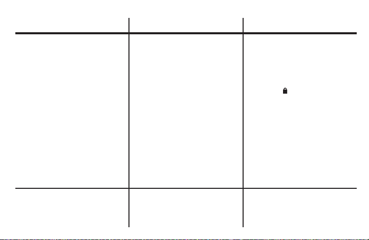
24
User Menu #
(PressMenubutton
and release)
Description
Default Setting
(ashingicons)
Settings
(Press or )
01
Fahrenheit or Celsius °F
°F – Fahrenheit
°C – Celsius
02
Temperature Display Adjustment:
adjust the Room Temperature)
0 -5 to +5
03
Continuous Display Light: keep
thebacklightalwayson–“C”wire
required
OFF
On – always on
OFF – momentarily
04
Auto Changeover: Thermostat
automatically switches between heat
and cool
OFF
On-enableauto
OFF-disableauto
05
Keypad Lock:preventunwanted
changes to the thermostat
OFF
On – disable buttons
OFF–allbuttonsareactive

25
6.2 Thermostat operation
• Away–Storeafrequentlyusedtemperaturesothatyoucaneasilyselectthatsettingwiththetouchofabutton.
Setupbyusing or to change the set point. At the desired set point, hold the Awaybuttonfor3seconds.
Oncetheinformationisstoredthesetpointwillashonetime.Performthisactiontostoreanawaysettingforboth
CoolandHeatmodes.(Example:Setanawaytemperatureto88°Finthesummerforcooland55°Finthewinter
for heat.)
• Keypad Lockout–Topreventunwantedchanges,thebuttonscanbedisabled.ToturnthisfeatureOn,pressand
hold and the Menu button until the icon appears (this can also be turned on in the menu). To turn Off, press
and hold and the Menubuttonfor3seconds.

26
7 SPECIFICATIONS
ElectricalRating:
BatteryPower ...................................................... mVto30VAC,NECClassII,50/60HzorDC
Input-Harwire ....................................................... 20to30VAC,NECClassII,50/60Hz
Terminal Load ......................................................... 1.5Aperterminal,2.5Amaximumallterminalscombined
SetpointRange ....................................................... 45°to99°F(7°to37°C)
RatedDifferentials(@6°F/Hr): Fast Med Slow
Heat(ConventionalGas/Oil/Elect) ................... 0.5°F 0.75°F 1.9°F
Cool (Central Air) ................................................. 0.9°F 1.2°F 1.7°F
HeatPump(HeatandCool) ................................ 0.9°F 1.2°F 1.7°F
HeatPumpAux. ................................................... 0.5°F 0.75°F 1.9°F
Operating Ambient .................................................. 32°Fto+105°F(0°to+41°C)
Display Temperature Range ................................... 32°Fto+99°F(0to37°C)
OperatingHumidity ................................................ 90%non-condensingmaximum
ShippingTemperatureRange ................................. -20°Fto+150°F(-29°to+65°C)
Thermostat Dimensions .......................................... 3-3/4”Hx6”Wx1-1/8”D

27
8. TROUBLESHOOTING
Symptom Possible Cause Corrective Action
NoHeat/NoCool/NoFan
(common problem)
1.Blownfuseortrippedcircuitbreaker
2. Furnace power switch to OFF
3.Furnaceblowercompartmentdooror
panel loose or not properly installed
4.Looseconnectiontothermostator
system
1.Replacefuseorresetbreaker.
2. Turn switch to ON.
3.Replacedoorpanelinproperpositionto
engage safety interlock or door switch.
4.Tightenconnections
NoHeat 1.SystemnotsettoHeat
2. Loose connection to thermostat or
system
3.HeatingSystemrequiresserviceor
thermostat requires replacement
1.SetthermostattoHeat.
2.Verifythermostatandsystemwiresare
securely attached.
3.Diagnostic:SetSystemtoHeatandraise
thesetpointaboveroomtemperature.
Withinveminutesthethermostatshould
makeasoftclicksoundand“HeatOn”
should appear on display.

28
Symptom Possible Cause Corrective Action
NoHeat(contd.) 3.(contd.)Thissoundindicatesthethermostatisoperating
properly.If the thermostat does not click, try the reset
operation listed below. If the thermostat does not click
afterbeingreset,contactyourheatingandcoolingservice
person or place of purchase for a replacement. If the
thermostat clicks, contact the furnace manufacturer or a
servicepersontoverifytheheatingsystemisoperating
correctly.
No Cool 1.SystemnotsettoCool
2. Loose connection to thermostat
or system
3.CoolingSystemrequires
serviceorthermostatrequires
replacement
1.SetthermostattoCool.
2.Verifythermostatandsystemwiresaresecurelyattached.
3.Diagnostic:SetSystemtoCoolandlowersetpointbelow
roomtemperature.Sameproceduresasdiagnosticfor
“NoHeat”conditionexceptsetthethermostattoCooland
lower the setpoint below the room temperature. There may
beuptoaveminutedelaybeforethethermostatclicksin
Coolingifthecompressorlock-outoptionisselectedinthe
installermenu.(seeINSTALLERMENU,item50)
29
Symptom Possible Cause Corrective Action
Heat,CoolorFanRunsConstantly. Possibleshortinwiring,thermostat,
heat, cool or fan system
Checkeachwireconnectiontoverify
they are not shorted or touching other
wires. Try resetting the thermostat. If the
conditionpersistscontactyourHVAC
serviceperson.
Thermostat Display &
Thermometer Disagree
Thermostat display requires adjustment Displaycanbeadjusted+/-5°.
SeeUserMenuitem05
Furnace (Air Conditioner) Cycles Too
FastorSlow(narroworwide
temperature swing)
The location of the thermostat and/or
thesizeoftheHeatingSystemmaybe
inuencingthecyclerate
Digitalthermostatsprovideprecise
control and cycle faster than older
mechanical models. The system turns
on and off more frequently, but runs for
a shorter time. If you would like to
increasecycletime,chooseSLOfor
slow cycle in the Installer menu.
(Referencemenuitems30,32&35)If
anacceptablecyclerateisnotachieved,
contactyourHVACserviceperson.
30
Symptom Possible Cause Corrective Action
“CallforService”iconappearson
displayed
1.Heatingsystemisnotabletoheat
thespacetowithin10degreesofthe
setpoint within 2 hours
2. Cooling system is not able to cool
thespacetowithin10degreesofthe
setpoint within 2 hours
3.If“--”isdisplayedfortheRoomTem-
perature, a replacement thermostat
is needed
4.Noneofthebuttonsoperateonthe
thermostat
5.If“CallforService”isashing,com-
pressor self diagnostic is detecting an
issue with the outdoor unit
1.Seecorrectiveactionfor“NoHeat”
2.Seecorrectiveactionfor“NoCool”
3.Replacethermostat
4.Makesurekeypadlockoutisnot
turned on ( ),Ifit’sOFF,tryreset
shown below.
5.Contactaservicepersontoverify
the outdoor equipment is operating
correctly
Heatpumpsystemrunsheatincool
mode/cool in heat mode
Changeover“O/B”setincorrectly Usecongurationtoswitch“O”to“B”
or“B”to“O”

31
Resetting the Thermostat or Thermostat Settings
If the thermostat has good batteries, but has a blank display or does not respond to key presses, the thermostat
shouldberesetbyremovingthebatteriesfor2minutes.Thisresetwillnotchangethemenusettingsorprogram.
If the condition persists after reinstalling the batteries, replace the thermostat.
Toconvenientlyresetonlythescheduleandusersettingsbacktofactorydefaults,pressMenu and Backlight
buttons at the same time and hold until the display goes blank and resets.

32
CONTACT US
Customer support:877.654.9394orwr[email protected]
MERCURY NOTICE
Thisproductdoesnotcontainmercury.However,thisproductmayreplaceaproductthatcontainsmercury.
Mercury and products containing mercury must not be discarded in household trash.
Refertothermostat-recycle.orgforlocationtosendproductcontainingmercury.
FOR CALIFORNIA RESIDENTS
Warning:ThisproductcontainsachemicalknowntothestateofCaliforniatocausecancerandbirthdefectsand
otherreproductiveharm.