FAILURE TO READ AND FOLLOW ALL INSTRUCTIONS CAREFULLY
BEFORE INSTALLING OR OPERATING THIS CONTROL COULD CAUSE
PERSONAL INJURY AND/OR PROPERTY DAMAGE.
DESCRIPTION
Your new White-Rodgers Digital Thermostat uses the technology
of a solid-state microcomputer to provide precise temperature
control.
Features:
• Simultaneousheatandcoolsetpointstorage
• Pre-settemperaturecontrol
• Backlitdisplay
• LCDcontinuouslydisplayssetpointandroomtemperature
• °F/°Cconvertibility
• Temperaturerange45°to90°F
• RC,RH,C,W,Y,G,OandBterminals
• OptionalCterminal(DualPoweroption)
• BandOterminalsforsinglestageheatpumps(noauxiliary
heat)ordamperoperation
• Setpointstorageincaseofpowerloss
• 2"AA"alkalinebatteriesincluded
SPECIFICATIONS
ELECTRICAL DATA
Electrical Rating:
8to30VAC50/60Hz.orD.C.
0.05to1.0Amps(Loadperterminal)
1.5 Amps Maximum Total Load(Allterminalscombined)
THERMAL DATA
Setpoint Temperature Range:
45°Fto90°F(7°Cto32°C)
Operating Ambient Temperature Range:
32°Fto105°F
Operating Humidity Range:
0to90%RH(non-condensing)
Shipping Temperature Range:
-4°Fto150°F
APPLICATIONS
Forusewith:
• Standardheat/coolorheatonlysystems
• Electricheatsystems
• Gasoroilredsystems
• Gassystemswithintermittentignitiondevices(I.I.D.)
and/orventdampers
• Hydronic(hotwaterorsteam)systems
• Single-stageheatpumpsystems(noauxiliaryheat)
• Millivoltsystems
DO NOT USE WITH:
• Multi-stagesystems
• Systemsexceeding30VACand1.5amps
• 3-wirezonedhydronicheatingsystems
1F86-344
Non-ProgrammableElectronicDigitalThermostat
PART NO. 37-6585C
Replaces37-6585B
1123
INSTALLATION AND
OPERATION INSTRUCTIONS
PRECAUTIONS
CAUTION
!
To prevent electrical shock and/or equipment damage,
disconnect electric power to system at main fuse or
circuit breaker box until installation is complete.
This thermostat is intended for use with a low voltage system;
donotusethisthermostatwithalinevoltagesystem.Ifindoubt
aboutwhetheryourwiringismillivolt,line,orlowvoltage,have
itinspectedbyaqualiedheatingandairconditioningcontrac-
tor or electrician.
Donotexceedthespecicationratings.
Allwiringmustconformtolocalandnationalelectricalcodes
and ordinances.
Thiscontrolisaprecisioninstrument,andshouldbehandled
carefully. Rough handling or distorting components could cause
the control to malfunction.
WARNING
!
Do not use on circuits exceeding specified voltage.
Higher voltage will damage control and could cause
shock or fire hazard.
Do not short out terminals on gas valve or primary
control to test. Short or incorrect wiring will damage
thermostat and could cause personal injury and/or
property damage.
Thermostat installation and all components of the sys-
tem shall conform to Class II circuits per the NEC code.
Operator: Save these instructions for future use!
www.white-rodgers.com
www.emersonclimate.com
2
INSTALLATION
REMOVE OLD THERMOSTAT
1. Shutoffelectricityatthemainfuseboxuntilinstallationis
complete.Ensurethatelectricalpowerisdisconnected.
2. Removethefrontcoveroftheoldthermostat.With wires
still attached, removewallplatefromthewall.Iftheold
thermostathasawallmountingplate,removethethermostat
andthewallmountingplateasanassembly.
3. Identify each wire attached to the old thermostat using
the labels enclosed with the new thermostat.
4. Disconnectthewiresfromoldthermostatoneatatime.DO
NOT LET WIRES FALL BACK INTO THE WALL.
5. Installnewthermostatusingthefollowingprocedures.
ATTENTION!
Thisproductdoesnotcontainmercury.However,thisproduct
may replace a unit which contains mercury.
Donotopenmercurycells.Ifacellbecomesdamaged,donot
touchanyspilledmercury.Wearingnonabsorbentgloves,take
upthespilledmercurywithsandorotherabsorbentmaterialand
placeintoacontainerwhichcanbesealed.Ifacellbecomes
damaged,theunitshouldbediscarded.
Mercurymustnotbediscardedinhouseholdtrash.Whenthe
unitthisproductisreplacingistobediscarded,placeinasuit-
ablecontainer.Refertowww.white-rodgers.comforlocationto
send product containing mercury.
ELECTRIC HEAT OR SINGLE-STAGE
HEAT PUMP SYSTEMS
Thisthermostatisconguredfromthefactorytooperateaheat/
cool,fossilfuel(gas,oil,etc.),forcedairsystem.Itiscongured
correctlyforanysystemthatDOESNOTrequirethethermostat
toenergizethefanonacallforheat.Ifyoursystemisanelectric
heatorheat-pumpsystemthatREQUIRESthethermostatto
turnonthefanonacallforheat,locatetheGAS/ELECTRIC
switch onthebackofthethermostat(seeg.1)andswitchitto
the ELECTRIC position.Thiswillallowthethermostattoenergize
thefanimmediatelyonacallforheat.Ifyouareunsureifthe
heating/coolingsystemrequiresthethermostattocontrolthefan,
contactaqualiedheatingandairconditioningserviceperson.
ATTACH THERMOSTAT BASE TO WALL
1. Removethepackingmaterialfromthethermostat.Gentlypullthe
coverstraightoffthebase.Forcingorpryingonthethermostat
willcausedamagetotheunit.Ifnecessary,movetheelectric
heatswitch(seeELECTRIC HEAT SYSTEMS,above).
2. Connectwiresbeneathterminalscrewsonbaseusingap-
propriatewiringschematic(seegs.2through7).
3. Placebaseoverholeinwallandmarkmountingholeloca-
tionsonwallusingbaseasatemplate.
4. Movebaseoutoftheway.Drillmountingholes.
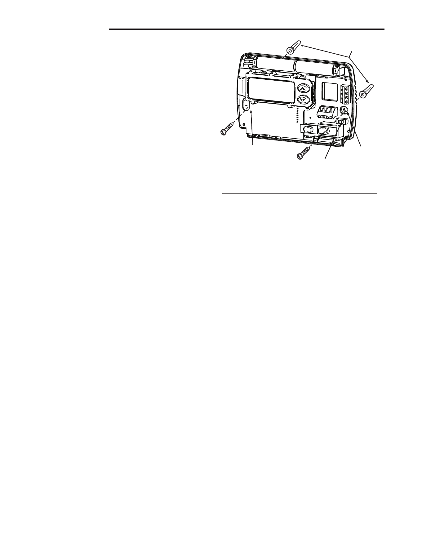
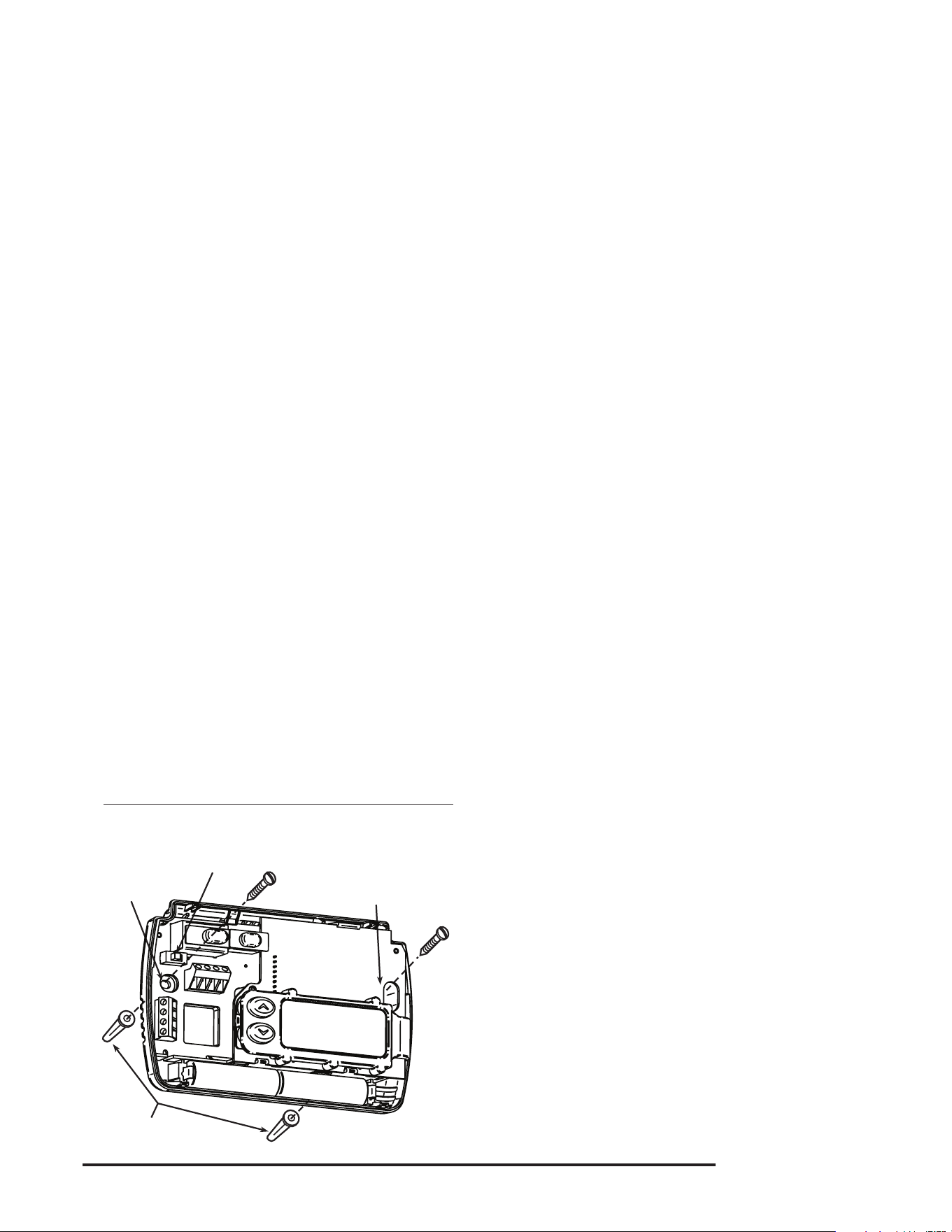
5. Fastenbaselooselytowall,asshowning.1,usingtwo
mounting screws. Place a level against bottom of base,
adjustuntillevel,andthentightenscrews.(Levelingisfor
appearanceonlyandwillnotaffectthermostatoperation.)
Ifyouareusingexistingmountingholes,orifholesdrilled
aretoolargeanddonotallowyoutotightenbasesnugly,
useplasticscrewanchorstosecuresubbase.
6. Pushexcesswireintowallandplugholewithare-resistant
material(suchasberglassinsulation)topreventdraftsfrom
affecting thermostat operation.
BATTERY LOCATION
2"AA"alkalinebatteriesareincludedinthethermostatatthe
factorywithabatterytagtopreventpowerdrainage.You must
remove the battery tag to engage the batteries.
If"LO BATTERY"isdisplayed,thebatteriesarelowandshould
bereplaced.Forbestresults,replaceallbatterieswithnewpre-
miumbrandalkalinebatteriessuchasDuracell
®
orEnergizer
®
.
Toreplacebatteries,installthebatteriesalongthetopofthe
base(seeFig.1).Thebatteriesmustbeinstalledwiththeposi-
tive(+)endtotheleft.
HYDRONIC (HOT WATER OR STEAM)
HEATING SYSTEMS
This thermostat is set to operate properly with a forced-air heat-
ingsystem.Ifyouhaveahydronicheatingsystem(asystem
thatheatswithhotwaterorsteam),youmustsetthethermostat
tooperateproperlywithyoursystem.Changethesecondop-
tioninthecongurationmenutoSL(seeCONFIGURATION
MENU,page4).
CHECK THERMOSTAT OPERATION
If at any time during testing your system does not operate
properly,contactaqualiedserviceperson.
Turn on power to the system.
Fan Operation
Ifyoursystemdoes not have a Gterminalconnection,skipto
Heating System.
1. MoveFANswitchto ONposition.Theblowershouldbegin
to operate.
2. MoveFANswitchtoAUTOposition.Theblowershouldstop
immediately.
Mounting
holes
Mounting
holes
Electric/Gas
switch
Screw anchors
Figure 1. Thermostat Base
3
RH
Y
24 VAC
120 VAC
Hot
Neutral
THERMOSTAT
SYSTEM
G W
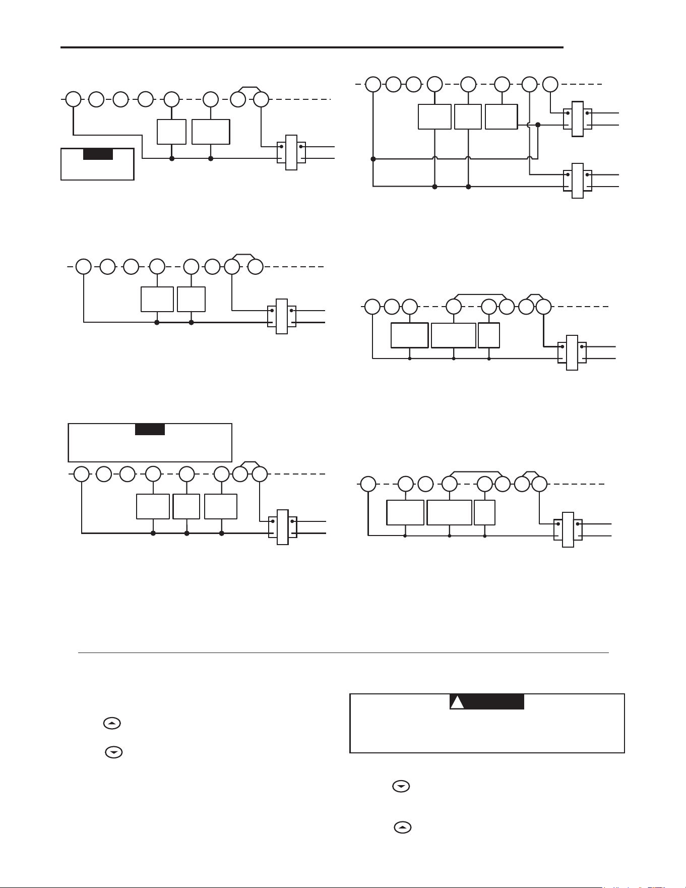
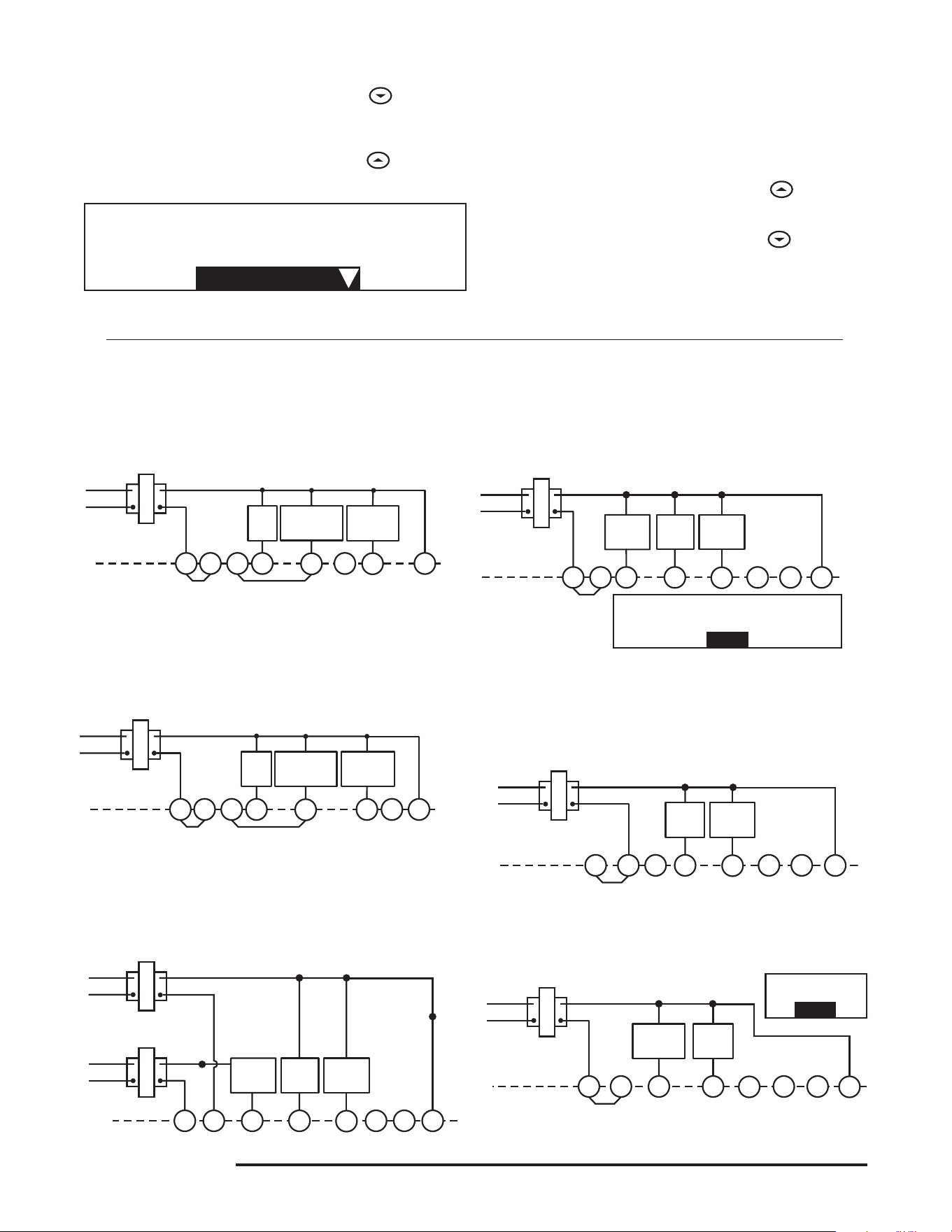
Figure 5. Typical wiring diagram for
heat/cool, 5-wire, two-transformer systems
HEATING
TRANSFORMER
Heating
System
Fan
Relay
Cooling
System
RC
24 VAC
120 VAC
Hot
Neutral
COOLING TRANSFORMER
OBC
‡
RH
Y
24 VAC
120 VAC
Hot
Neutral
THERMOSTAT
SYSTEM
G W
Figure 4. Typical wiring diagram for
heat/cool, 4-wire, single transformer systems
TRANSFORMER
Heating
System
Fan
Relay
Cooling
System
RC
JUMPER
WIRE
OC
‡
B
RED jumper wire (provided with thermostat) must be
connected between thermostat RH and RC terminals
for proper thermostat operation with this system.
NOTE
RH
24 VAC
120 VAC
Hot
Neutral
THERMOSTAT
SYSTEM
G W
Figure 2. Typical wiring diagram for
heat only, 3-wire, single transformer systems
TRANSFORMER
Heating
System
Fan
Relay
YC
‡
RC
JUMPER
WIRE
OB
For 2-wire Heat only,
attach to RH and W
NOTE
RH
Y
24 VAC
120 VAC
Hot
Neutral
THERMOSTAT
SYSTEM
G W
Figure 7. Typical wiring diagram for heat pump
with reversing valve energized in HEAT
TRANSFORMER
Reversing
Valve*
RCO
B
C
‡
JUMPER
WIRE
Compressor
Contactor
JUMPER
WIRE
* Reversing valve is energized when the
system switch is in the HEAT position
Fan
Relay
RH
Y
24 VAC
120 VAC
Hot
Neutral
TRANSFORMER
THERMOSTAT
SYSTEM
G W
Figure 3. Typical wiring diagram for
cool only, 3-wire, single transformer systems
Cooling
System
Fan
Relay
RCOB
C
‡
JUMPER
WIRE
RH
Y
24 VAC
120 VAC
Hot
Neutral
THERMOSTAT
SYSTEM
G W
Figure 6. Typical wiring diagram for heat pump
with reversing valve energized in COOL
TRANSFORMER
Reversing
Valve*
RCOBC
‡
JUMPER
WIRE
Compressor
Contactor
JUMPER
WIRE
* Reversing valve is energized when the
system switch is in the COOL position
Fan
Relay
Heating System
1. MoveSYSTEMswitchtoHEATposition.Iftheheatingsystem
hasastandingpilot,besuretolightit.
2. Press
toadjustthermostatsettingaboveroomtempera-
ture.Theheatingsystemshouldbegintooperate.
3. Press
toadjusttemperaturesettingbelowroomtem-
perature. The heating system should stop operating.
Cooling System
1. MoveSYSTEMswitchtoCOOL position.
2. Press
toadjustthermostatsettingbelowroomtempera-
ture.Theblowershouldcomeonimmediatelyonhighspeed,
followedbycoldaircirculation.
3. Press
toadjusttemperaturesettingaboveroomtem-
perature. The cooling system should stop operating.
CAUTION
!
To prevent compressor and/or property damage, if the
outdoor temperature is below 50°F, DO NOT operate
the cooling system.
‡
The 24 Volt neutral connection to terminal C on the thermostat is not required if the batteries are replaced once a
year with fresh premium brand alkaline batteries.
WIRING
4
CONFIGURATION MENU
Thecongurationmenuallowsyoutosetcertainthermostatop-
eratingcharacteristicstoyoursystemorpersonalrequirements.
MoveSYSTEMswitchtotheOFFposition,thenpress
and
atthesametimetoenterthecongurationmenu.Thedisplay
willshowtherstiteminthecongurationmenu.
Thecongurationmenuchartbelowsummarizesthecongura-
tionoptions.Anexplanationofeachoptionfollows.
Press
and tochangetothenextmenuitem.Toexitthe
menu,movetheSYSTEMswitchtoHEAT or COOL.Ifnokeys
arepressedwithinfteenminutes,thethermostatwillexitthe
congurationmenu.
1
Step Press Button(s) Displayed (Factory Default) Press or to select: COMMENTS
Set SYSTEM
switch to OFF
Set SYSTEM
switch to HEAT
or COOL
2
(FA)
SL
SYSTEM switch must be OFF to configure thermostat
options
8
LOC
(OFF)
ON
0 HI
(0)
4 LO to
4 HI
(F) C
Returns to normal operation
Select Compressor lockout OFF or ON
Select temperature display adjustment higher or lower
Select temperature display to F or C
and
3
d-L
(ON)
OFF
Select display backlight OFF or ON
Select FA or SL (Fast or Slow) heating cycle rate
Configuration Menu
* Press and
to advance to next item
and
and
and
and
4
5
6
7
FILTER
(000)
0 to 1950 hours
(in 50 hour increments)
Select Filter replacement run time
and
Beforeyoubeginusingyourthermostat,youshouldbefamiliar
with its features and with the display and the location and op-
erationofthethermostatbuttons.Yourthermostatconsistsof
twoparts:thethermostat cover and the base. To remove the
cover,pullitstraightoutfromthebase.Toreplacethecover,
lineupthecoverwiththebaseandpressuntilthecoversnaps
ontothebase.
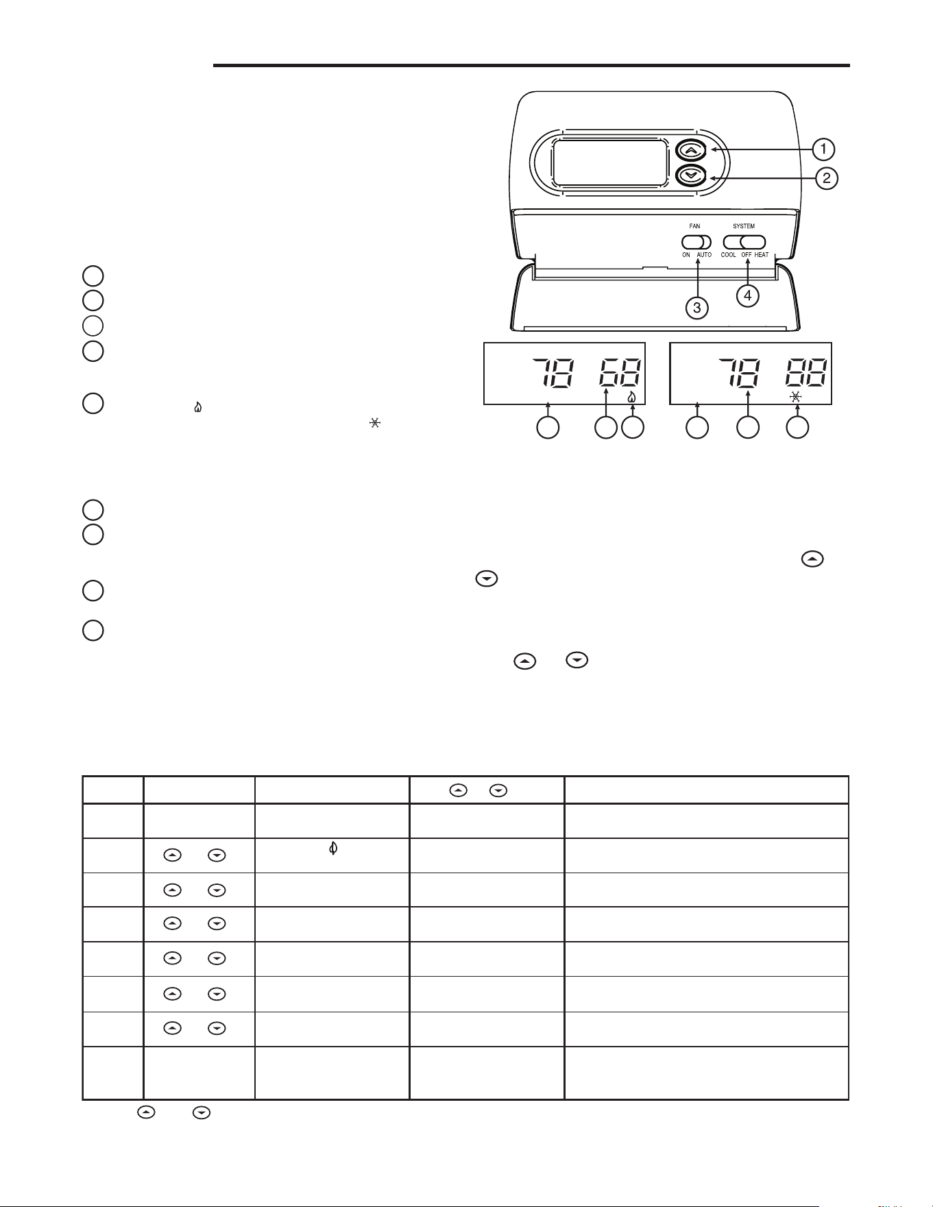
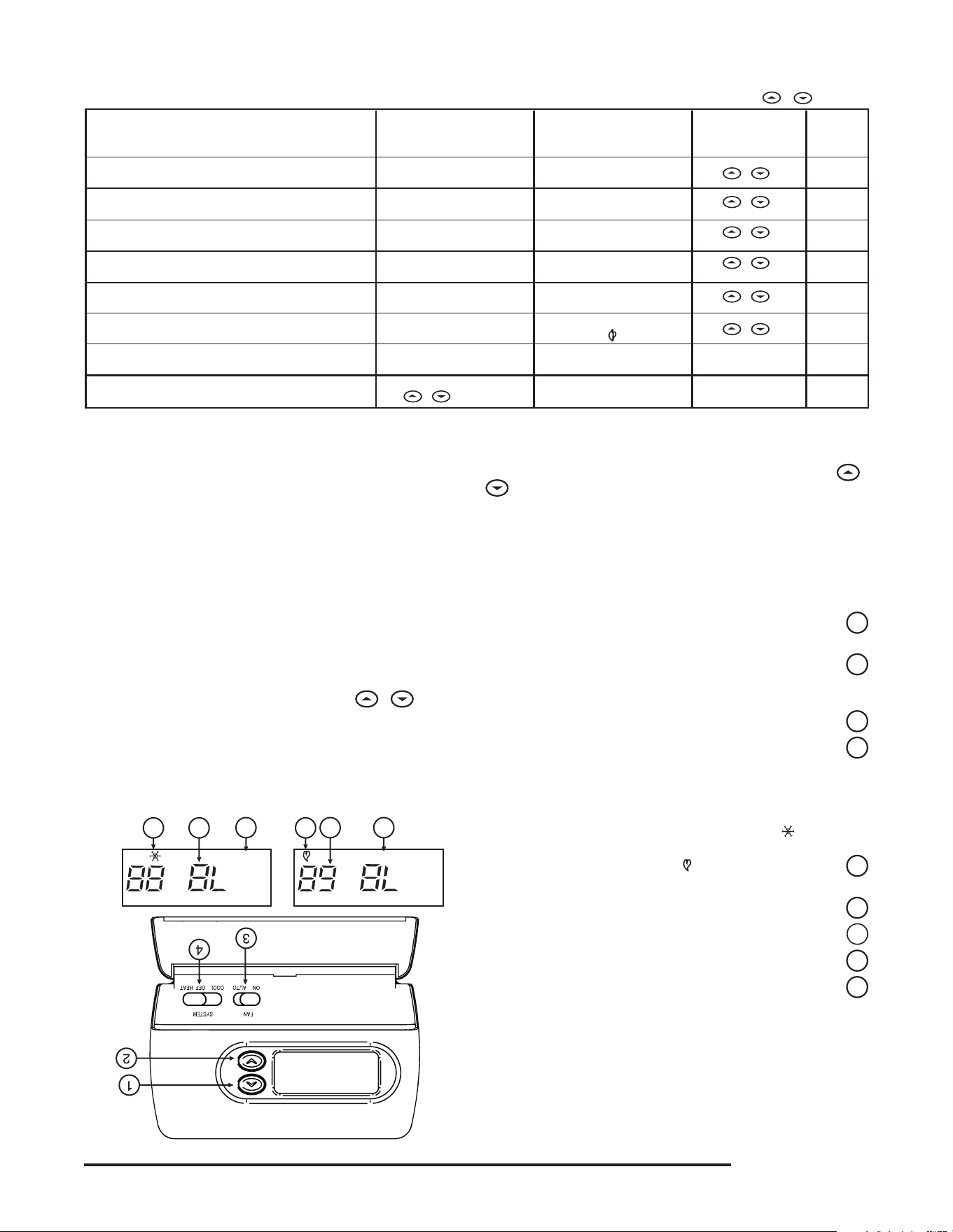
The Thermostat Buttons and Switches
(see fig. 8)
1
Raises temperature setting.
2
Lowerstemperaturesetting.
3
FANswitch(ON,AUTO).
4
SYSTEMswitch(COOL,OFF,HEAT).
The Display
5
Flame icon(
) is displayed when the SYSTEM switch
is in the HEAT position. Snowflake icon( )isdisplayed
(non-ashing)whentheSYSTEMswitchisintheCOOL
position. Snowflakeisdisplayed(ashing)ifthethermostat
isinlockoutmodetopreventthecompressorfromcycling
tooquickly.
6
Displays current temperature.
7
Displays "FILTER" when the system has run for the selected
ltertimeperiodasaremindertochangeorcleanyourair
lter.
8
Displayssetpointtemperature(thisisblankwhenSYSTEM
switch is in the OFFposition).
9
Displays "BATTERY" and "LO" in the current temperature
locationwhenthe2"AA"batteriesarelowandshouldbe
replaced.
5
8 79
56
Figure 8. Thermostat display, buttons, and switches
FC
RETLIFYRETTAB
OPERATION
5
2) Select FA or SL (Fast or Slow) Heating Cycle Rate - The
FAsettingisfrequentlyusedforgas,oilorelectricheat.The
SLsettingproducesalongerheatingcyclewhichisnormally
for hot water or steam(hydronic) systems. Both settings
produceveryaccuratetemperaturecontrolandcanbeset
toyourpersonalpreference.FAcyclesthesystemjustunder
1°FandtheSLsettingcyclesatapproximately1.5°F.
3) Select Display Backlight (d-L OFF or ON) - The display
backlightimprovesdisplaycontrastinlowlightingconditions.
SelectingbacklightONwillkeepthelightonforashortperiod
oftimeafteranykeyispressed.SelectingOFFwillkeepthe
light off.
4) Select filter replacement run time - The thermostat will
display "FILTER" after the selected time of operation. This is
aremindertochangeorcleanyourairlter.Thistimecanbe
setfrom0to1950hoursin50hourincrements.A selection
of 000 will cancel this feature. When "FILTER"isdisplayed,
youcanclearitbypressing
and at the same time.
This resets the timer and starts counting the hours until the
nextlterchange.
5) Select Compressor Lockout (LOC OFF or ON)-Selecting
LOCONwillcausethethermostattowait5minutesbefore
turning on the compressor if the heating and cooling system
losespower.Itwillalsowait5minutesminimumbetween
cooling cycles. This is intended to help protect the compres-
sorfromshortcycling.Somenewercompressorsalready
haveatimedelaybuiltinanddonotrequirethisfeature.
Your compressor manufacturer can tell you if the feature is
already present in their system. When the compressor time
delayoccursitwillashthe(snowakeicon)foraboutve
minutes then turn on the compressor.
6) Select Temperature Display Adjustment (4 LO to 4
HI)-Allowsyoutoadjusttheroomtemperaturedisplay4°
higherorlower.Yourthermostatwasaccuratelycalibrated
atthefactorybutyouhavetheoptiontochangethedisplay
temperature to match your previous thermostat.
7) Select Temperature DIsplay (°F or °C) -Changesthedisplay
readouttoCelsiusorFahrenheitasrequired.
OPERATING FEATURES
Nowthatyouarefamiliarwiththethermostatbuttonsanddisplay,
readthefollowinginformationtolearnaboutthemanyfeatures
of the thermostat.
• SIMULTANEOUS HEATING/COOLING SETPOINT STOR-
AGE —Youcanenterbothyourheatingandcoolingset
points at the same time. There is no need to change the
thermostatatthebeginningofeachseason.
• CONFIGURATION MENU — Allows you to customize
certain thermostat options.
SETTING THE THERMOSTAT
This thermostat is very easy to operate. Set the SYSTEM
switch to either HEAT or COOL then press
or until the
temperature you want to maintain is shown on the right side
ofthedisplay.Ifyouwanttoturnthesystemoff,justmovethe
SYSTEMswitchtoOFF.
The FAN switch controls the fan operation. When the FAN
switch is set to AUTO,thefanwillcyclewiththefurnaceorair
conditioner.WhentheFANswitchissettoON,thefanwillrun
continuously,regardlessofSYSTEMswitchposition.
TROUBLESHOOTING
No Heating
With the SYSTEM switch set to HEAT, when the setpoint
temperatureisraisedorloweredpasttheroomtemperature,
thethermostatwillmakeasoftclicksound.Usually,thesound
indicatesthe thermostat isoperating correctly.If thesystem
doesnotcomeon,checkthesystemorcontactyourheating/
coolingserviceperson.Ifthethermostatdoesnotclicktrythe
ResetOperationlistedbelow.
No Cooling
SameprocedureasheatingexceptsetSYSTEMswitchtoCOOL.
Therecanbeuptoa5minutecompressorlock-outtimedelay
beforethethermostatclicksinCOOL.
Blank Display
A blank digital display usually indicates the thermostat has
receivedavoltagespike,staticdischargeorrequiresnewbat-
teries.Ifthedisplayremainsblankafterreplacingthebatteries,
seeResetOperationbelow.
Reset Operation
Ifavoltagespikeorstaticdischargeblanksoutthedisplayor
causes erratic thermostat operation you can reset the thermostat
bypressing
, andmovetheSYSTEMswitchfromOFF to
HEAT at the same time. This also resets the factory defaults
to the configuration menu.Ifthethermostathaspower,has
beenreset andstill doesnot functioncorrectly contactyour
heating/coolingservicepersonorplaceofpurchase.
OPERATION

HOMEOWNER HELP LINE: 1-800-284-2925
www.white-rodgers.com
www.emersonclimate.com
White-Rodgers is a division
ofEmersonElectricCo.
TheEmersonlogoisa
trademarkandservicemark
ofEmersonElectricCo.
LÍNEA DE AYUDA PARA EL USUARIO: 1-800-284-2925
www.white-rodgers.com
www.emersonclimate.com
White-Rodgers es una división
deEmersonElectricCo.
El logotipo de Emerson es una
marca comercial y una marca
deserviciodeEmersonElectricCo.
5
2) Seleccione Display Backlight (luz de fondo de pantalla) (d-L
OFF [desactivada] u ON [activada]) - La luz de fondo mejora el
contraste de la pantalla en condiciones de poca luz. Si selecciona
backlight ON, la luz se mantendrá encendida durante un breve
tiempo después de presionar cualquier botón. Si selecciona OFF,
la luz se mantendrá apagada.
3) Seleccione filter replacement run time (tiempo de ejecución de
reemplazo de filtro) - El termostato mostrará “FILTER” después
del tiempo de funcionamiento seleccionado. El propósito de este
mensaje es recordarle que cambie o limpie el filtro de aire. El tiempo
puedeajustarsedesde0hasta1950horasenincrementosde50
horas. Si elige 000, se cancelará esta función. Cuando aparece
“FILTER”, puede borrarlo presionando
y al mismo tiempo.
Deestamaneravolveráaceroelrelojysecomenzaránacontar
las horas que faltan hasta el siguiente cambio de filtro.
4) Seleccione Compressor Lockout (bloqueo del compresor) (LOC
OFF [desactivado] u ON [activado]) Si selecciona LOC ON el
termostatoesperará5minutosparaencenderelcompresorsiel
sistema de calefacción y refrigeración deja de recibir alimentación
eléctrica.Tambiénesperará5minutoscomomínimoentreciclos
de refrigeración para evitar que el compresor realice ciclos de
encendidoyapagadocortos.Algunoscompresoresmásnuevos
ya tienen incorporada una demora de tiempo y no requieren esta
función.Consultealfabricantedesucompresorparasabersisu
modeloincluyeconestafunción.Cuandoseproducelademora
detiempodelcompresor,el(iconodelcopodenieve)sepone
en intermitente durante unos cinco minutos y luego enciende el
compresor.
5) Seleccione Temperature Display Adjustment (ajuste de la
pantalla de temperatura) (4 LO [más abajo] a 4 HI [más arriba]) -
Lepermiteajustarlapantalladetemperaturaambiente4°másarriba
o más abajo. El termostato viene calibrado con precisión de fábrica
pero usted tiene la opción de cambiar el valor de temperatura que
aparece en la pantalla para que coincida con el de su termostato
anterior.
6) Seleccione Temperature Display (visualización de temperatura)
(F° o C°) -Cambialaunidadenqueaparecelatemperaturaenla
pantallaagradosCelsiusoFahrenheitsegúnsupreferencia.
FUNCIONES DEL TERMOSTATO
Ahora que está familiarizado con los botones del termostato y la
pantalla, lea la siguiente información para conocer las diferentes
funciones del termostato.
• ALMACENAMIENTO SIMULTÁNEO DE TEMPERATURAS
DE REFERENCIA DE CALEFACCIÓN/REFRIGERACIÓN —
Puedeingresarsustemperaturasdereferenciadecalefacción
y refrigeración al mismo tiempo. No es necesario realizar
modificaciones en el termostato al comienzo de cada estación.
• MENÚ DE CONFIGURACIÓN — Le permite personalizar ciertas
opciones del termostato.
AJUSTE DEL TERMOSTATO
Estetermostatoesmuysencillodeoperar.AjusteelinterruptorSYSTEM
en HEAT o COOL y luego presione
o hasta que la temperatura
que desea mantener aparezca a la derecha de la pantalla. Si desea
apagarelsistema,simplementemuevaelinterruptorSYSTEMala
posición OFF.
ElinterruptorFANcontrolaelfuncionamientodelventilador.Cuandoel
interruptorFANsecolocaenAUTO, el ventilador se encenderá y se
apagaráconlacalderaoelaireacondicionado.CuandoelinterruptorFAN
está ajustado en ON, el ventilador funcionará de manera ininterrumpida,
independientementedelaposicióndelinterruptorSYSTEM.
SOLUCIÓN DE PROBLEMAS
El sistema no calienta
ConelinterruptorSYSTEMajustadoenHEAT, cuando la temperatura
de referencia se sube o se baja por encima o debajo de la temperatura
ambiente,eltermostatoemitiráunchasquidosuave.Porlogeneral,el
sonido indica que el termostato está funcionando correctamente. Si el
sistema no se enciende, verifique el sistema o póngase en contacto
consuserviciotécnicodecalefacción/refrigeración.Sieltermostato
no emite un chasquido, siga el procedimiento indicado en la sección
Operacióndereajusteacontinuación.
El sistema no enfría
Siga el mismo procedimiento que para calefacción colocando el
interruptorSYSTEMen COOL. Es posible que haya una demora del
bloqueodelcompresordehasta5minutosantesdequeeltermostato
se active en COOL.
La pantalla está en blanco
Por lo general, una pantalla digital en blanco indica que el
termostato ha recibido un pico de voltaje o una descarga estática
o que es necesario cambiar las pilas. Si la pantalla permanece
en blanco después de cambiar las pilas, vea la sección
Operacióndereajusteacontinuación.
Operación de reajuste
Si un pico de voltaje o una descarga estática pone en blanco la
pantalla o hace que el termostato funcione de manera errática,
puede reajustarlo presionando
y y moviendo el
interruptor SYSTEM de OFF a HEAT al mismo tiempo. De esta
manera, también reajustará los valores predeterminados de
fábrica según el menú de configuración. Si el termostato tiene
alimentaciónysehareajustadoperoaúnnofuncionacorrectamente,
póngaseencontactoconsuserviciotécnicodecalefacción/refrigeración
o con el lugar donde realizó la compra.
OPERACIÓN
4
Enelcuadrodelmenúdeconguraciónacontinuaciónseresumen
las diferentes opciones de configuración disponibles, seguidas por una
explicación de cada una.
Presione
y parapasaralasiguienteopcióndelmenú.Para
salirdelmenú,muevaelinterruptorSYSTEMaHEAT o COOL. Si
pasanquinceminutossinpresionarningúnbotón,eltermostatosaldrá
delmenúdeconguración.
1) Seleccione FA o SL (rápida o lenta) para Heating Cycle Rate
(velocidad del ciclo de calefacción)-LaconguraciónFAsuele
utilizarse para sistemas de calefacción de gas, aceite o eléctricos. La
configuración SL produce un ciclo de calefacción más largo que lo
normalparasistemasdeaguacalienteovapor(hidrónicos).Ambas
configuraciones producen un control de temperatura sumamente
exacto y pueden ajustarse según su preferencia personal. La
conguraciónFAapagayenciendeelsistemadebajode1°Fyla
conguraciónSLlohaceaaproximadamente1.5°F.
* Presione y para pasar a la siguiente opción del menú.
1
Paso
Ajuste el interruptor
SYSTEM en OFF
Ajuste el
interruptor SYSTEM
en HEAT o COOL
2
(FA)
SL
El interruptor SYSTEM debe estar en OFF para configurar
las opciones del termostato
8
LOC
(OFF)
ON
0 HI
(0)
4 LO a
4 HI
(°F) °C
Vuelve al funcionamiento normal
Selecciona el bloqueo del compresor en OFF (desactivado) u
ON (activado)
Selecciona el ajuste de la temperatura visualizada más
arriba o más abajo
3
d-L
(ON)
OFF
Selecciona luz de fondo de pantalla OFF (apagada) u
ON (encendida)
Selecciona FA o SL (rápida o lenta) para la velocidad
del ciclo de calefacción
Menú de configuración
4
5
6
7
FILTER
(000)
0 a 1950 horas
(en incrementos de 50 horas)
Selecciona el tiempo de ejecución de reemplazo del filtro
La pantalla muestra
(ajustado de fábrica)
Presione el botón
o botones
OBSERVACIONES
Presione o
para seleccionar:
y
y
y
y
y
y
Selecciona la visualización de la temperatura en °F o °C
Antesdequecomienceausarsutermostato,debefamiliarizarsecon
sus funciones y con la pantalla y la ubicación y funcionamiento de los
diferentesbotones.Sutermostatoconstadedospartes:lacubierta del
termostato y la base.Pararetirarlacubierta,tiresuavementedeella
parasepararladelabase.Paravolveracolocarla,alineelacubierta
con la base y presione suavemente hasta que se enganche en la base.
Los botones e interruptores del termostato
(vea la figura 8)
1
Sube el ajuste de temperatura.
2
Bajaelajustedetemperatura.
3
InterruptorFAN(ventilador)(ON, AUTO).
4
InterruptorSYSTEM(COOL, OFF, HEAT).
La pantalla
5
El icono de la llama ( ) aparece cuando el interruptor
SYSTEM está en la posición HEAT. El icono del copo de
nieve ( ) aparece (fijo) cuando el interruptor SYSTEM
está en la posición COOL. El copo de nieve aparece
(intermitente)cuandoeltermostatoestáenelmododebloqueo
para evitar que el compresor realice ciclos de encendido y apagado
demasiado cortos.
6
Muestralatemperaturaactual.
7
Muestra "FILTER" cuando el sistema se ha utilizado por la
cantidad de tiempo seleccionada en el filtro para recordarle que
debe cambiar o limpiar el filtro de aire.
8
Muestralatemperaturadereferencia(apareceenblancocuando
elinterruptorSYSTEMestáenlaposiciónOFF).
9
Muestra "BATTERY" y "LO" en lugar de la temperatura
cuando las 2 pilas “AA” tienen poca carga y deben
cambiarse.
MENÚ DE CONFIGURACIÓN
El menú de conguración lepermite ajustarciertas características
operativas del termostato según el sistema o sus necesidades
particulares.
MuevaelinterruptorSYSTEMalaposiciónOFF y luego presione
y almismotiempoparaingresarenelmenúdeconguración.La
pantallamostrarálaprimeraopcióndelmenúdeconguración.
OPERACIÓN
5
8 79
56
FC
RETLIFYRETTAB
Figura 8. Pantalla, botones e interruptores del termostato
3
RH
Y
24 VAC
120 VAC
Vivo
Neutro
SISTEMA
TERMOSTATO
G W
Figura 5. Diagrama de conexiones típico para sistemas
de calor/frío de dos transformadores y 5 cables
TRANSFORMADOR
DE CALEFACCIÓN
RC
24 VAC
120 VCA
Vivo
Neutro
TRANSFORMADOR DE REFRIGERACIÓN
OBC
‡
Sistema
de
refrigeración
Relé
del
ventilador
Sistema
de
calefacción
VCA
VCA
VCA
RH
Y
24 VAC
120 VAC
Vivo
Neutro
SISTEMA
TERMOSTATO
G W
Figura 4. Diagrama de conexiones típico para sistemas
de calor/frío de un solo transformador y 4 cables
TRANSFORMADOR
RC
CABLE
DE PUENTE
OC
‡
B
El cable de puente ROJO (suministrado con el termostato) debe
conectarse entre las terminales RH y RC del termostato para que
funcione en forma adecuada con este sistema.
NOTA
Sistema
de
refrigeración
Relé
del
ventilador
Sistema
de
calefacción
VCA
VCA
RH
24 VAC
120 VAC
Vivo
Neutro
SISTEMA
TERMOSTATO
G W
Figura 2. Diagrama de conexiones típico para sistemas
de sólo calor de un solo transformador y 3 cables
TRANSFORMADOR
Sistema
de
calefacción
Relé
del
ventilador
YC
‡
RC
CABLE
DE PUENTE
OB
Para sólo calor con 2 cables,
conectar a RH y W
NOTA
VCA
VCA
RH
Y
24 VCA
120 VCA
Vivo
Neutro
SISTEMA
TERMOSTATO
G W
Figura 7. Diagrama de conexiones típico para una bomba
de calor con válvula inversora energizada en HEAT
TRANSFORMADOR
RCO
B
C
‡
CABLE
DE PUENTE
CABLE
DE PUENTE
* La válvula inversora se energiza cuando el
interruptor del sistema está en la posición HEAT
Válvula
inversora*
Contactor
del
compresor
Relé
del
ventilador
RH
Y
24 VAC
120 VCA
Vivo
Neutro
TRANSFORMADOR
SISTEMA
TERMOSTATO
G W
Figura 3. Diagrama de conexiones típico para sistemas
de sólo frío de un solo transformador y 3 cables
Relé
del
ventilador
RCOB
C
‡
CABLE
DE PUENTE
Sistema
de
refrigeración
VCA
RH
Y
24 VCA
120 VCA
Vivo
Neutro
SISTEMA
TERMOSTATO
G W
Figura 6. Diagrama de conexiones típico para una bomba
de calor con válvula inversora energizada en COOL
TRANSFORMADOR
Válvula
inversora*
RCOBC
‡
CABLE
DE PUENTE
Contactor
del
compresor
CABLE
DE PUENTE
* La válvula inversora se energiza cuando el
interruptor del sistema está en la posición COOL
Relé
del
ventilador
Sistema de calefacción
1. Mueva el interruptor SYSTEM a la posición HEAT.
Si el sistema de calefacción tiene un piloto, asegúrese de
encenderlo.
2. Presione
para ajustar la configuración del termostato por
encima de la temperatura ambiente. El sistema de calefacción
debería comenzar a funcionar.
3. Presione
para ajustar la configuración de la temperatura por
debajo de la temperatura ambiente. El sistema de calefacción
debería dejar de funcionar.
Sistema de refrigeración
1. MuevaelinterruptorSYSTEMalaposiciónCOOL.
2. Presione para ajustar la configuración del termostato por
debajo de la temperatura ambiente. El soplador debería encenderse
inmediatamente a alta velocidad, seguido de circulación de aire
frío.
3. Presione
para ajustar la configuración de la temperatura por
encima de la temperatura ambiente. El sistema de refrigeración
debería dejar de funcionar.
INSTALACIÓN
‡
No se requiere la conexión neutra de 24 voltios a la terminal C del termostato si las pilas se cambian una
vez al año por pilas alcalinas nuevas de alguna marca líder.
¡PRECAUCIÓN!
!
Para evitar daños al compresor y/o daños materiales,
si la temperatura externa está por debajo de los 50°F,
NO utilice el sistema de refrigeración.
2
INSTALACIÓN
RETIRE EL TERMOSTATO VIEJO
1. Apaguelaelectricidadenlacajadefusiblesprincipalhastaque
hayanalizadolainstalación.Asegúresedequelaalimentación
eléctrica esté desconectada.
2. Retirelacubiertadelanteradeltermostatoviejo.Con los cables
aún conectados, retire la placa de la pared. Si el termostato viejo
tiene una placa de montaje sobre pared, retire el termostato y la
placa juntos.
3. Identifique cada uno de los cables conectados al termostato
viejo usando las etiquetas incluidas con el nuevo termostato.
4. Desconecte loscables deltermostato viejode a unoa la vez.
NO DEJE QUE LOS CABLES VUELVAN A INTRODUCIRSE EN
LA PARED.
5. Instaleeltermostatonuevosiguiendoelprocedimientoindicadoa
continuación.
¡ATENCIÓN!
Este producto no contiene mercurio. No obstante, puede reemplazar una
unidad que sí contiene mercurio.
No abra las celdas de mercurio. En el caso de que una celda se dañe, no
toque el mercurio derramado. Usando un par de guantes no absorbentes,
recoja el mercurio derramado con arena u otro material absorbente y
viértalo en un recipiente que pueda sellarse. Si se daña una celda, debe
desecharse la unidad.
Elmercurionodebedesecharseconlosresiduosdomésticos.Para
desechar la unidad que será reemplazada por este equipo, colóquela en
unrecipienteadecuado.Consulteenwww.white-rodgers.comdóndeenviar
los productos que contienen mercurio.
SISTEMAS DE CALOR ELÉCTRICOS O DE
BOMBA DE CALOR DE UNA SOLA ETAPA
Este termostato está configurado de fábrica para operar un sistema
deaireforzadoconcombustiblefósil(gas,aceite,etc.)decalor/frío.
EstácorrectamenteconguradoparacualquiersistemaqueNOrequiera
que el termostato energice el ventilador en una llamada de calor. Si su
sistemaesunsistemaeléctricoodebombadecalorqueREQUIERE
que el termostato encienda el ventilador en una llamada de calor, ubique
el interruptor GAS/ELECTRIC(vealagura1)ycolóqueloenla
posición ELECTRIC. Esto permitirá al termostato energizar el ventilador
inmediatamente en una llamada de calor. Si no está seguro si el sistema
decalefacción/refrigeraciónrequiere queeltermostato controleel
ventilador, póngase en contacto con un servicio técnico de calefacción
y aire acondicionado calificado.
FIJE LA BASE DEL TERMOSTATO
A LA PARED
1. Retire el material de embalaje del termostato. Tire suavemente
de la cubierta para separarla de la base. Si fuerza o hace palanca
sobre el termostato dañará la unidad. Si es necesario, mueva
el interruptor de calor eléctrico (vea la sección SISTEMAS DE
CALOR ELÉCTRICOSmásarriba).
2. Conecte los cables que se encuentran debajo de los tornillos
terminales a la base consultando el esquema de conexiones
apropiado(vealasguras2a7).
3. Coloquelabasesobreeloriciodelaparedymarquelasubicaciones
de los orificios de montaje usando la base como plantilla.
4. Muevalabaseaunlado.Perforelosoriciosdemontaje.
5. Fijelabasealaparedsinajustarlademasiado,comomuestrala
gura1,usandodostornillosdemontaje.Coloqueunnivelcontrala
parteinferiordelabase,ajústelahastaquequedebienniveladay
luegoaprietelostornillos.(Estoesporrazonesestéticassolamente
y no afectará el funcionamiento del termostato.) Si utiliza los
orificios de montaje existentes, o si los orificios perforados
son demasiado grandes y no le permiten ajustar bien la base,
use anclajes plásticos para fijar la subbase.
6. Empujeelcablequesobresalehaciaelinteriordelaparedytapeel
oricioconunmaterialignífugo(comoaislamientodebradevidrio)
para evitar que las corrientes de aire afecten el funcionamiento del
termostato.
UBICACIÓN DE LAS PILAS
Eltermostatovienedefábricacon2pilasalcalinas“AA”unidasentre
sí para evitar que se descarguen. Debe retirar la tira de papel para
poder enganchar las pilas en su lugar.
Si aparece el mensaje "LO BATTERY", significa que las pilas tienen
pocacargaydebencambiarse.Paraobtenerresultadosóptimos,cambie
todas las pilas por pilas alcalinas nuevas de alguna marca líder como
Duracell
®
o Energizer
®
.Paracambiarlaspilas,instálelasalolargode
lapartesuperiordelabase(vealagura1).Laspilasdebeninstalarse
conlospolospositivos(+)hacialaizquierda.
SISTEMAS DE CALEFACCIÓN HIDRÓNICOS
(AGUA CALIENTE O VAPOR)
Este termostato está configurado para funcionar en forma
adecuada con un sistema de calefacción de aire forzado. Si tiene
un sistema de calefacción hidrónico (un sistema que genera
calor con agua caliente o vapor), debe congurar el termostato
para que funcione de manera adecuada con su sistema.
Cambie la segunda opción en el menú de conguración a SL
(veaelMENÚDECONFIGURACIÓNenlapágina4).
VERIFIQUE EL FUNCIONAMIENTO DEL
TERMOSTATO
Si en algún momento durante la prueba su sistema no
funciona correctamente, póngase en contacto con un
servicio técnico calificado.
Encienda la alimentación del sistema.
Funcionamiento del ventilador
Si su sistema no tiene una conexión terminal G, pase directamente a
la sección Sistema de calefacción.
1. MuevaelinterruptorFANalaposiciónON. El soplador debería
comenzar a funcionar.
2. MuevaelinterruptorFANalaposiciónAUTO. El soplador debería
detenerse inmediatamente.
Orificios
de montaje
Orificios
de montaje
Interruptor
eléctrico/de gas
Tarugos plásticos
Anclajes
Figura 1. Base del termostato
Este termostato está diseñado para ser utilizado con un sistema de bajo
voltaje; no utilice este termostato con un sistema de voltaje de línea.
Si tiene dudas acerca de si su conexión eléctrica es milivoltio, de línea
o de bajo voltaje, hágala inspeccionar por un técnico especializado en
equipos de calefacción y aire acondicionado o por un electricista autorizado.
No exceda los valores nominales especificados.
Todas las conexiones eléctricas deben cumplir con los códigos y
reglamentaciones locales y nacionales.
Este control es un instrumento de precisión y debe manipularse con
cuidado. La manipulación descuidada o la distorsión de los componentes
podrían hacer que el control no funcionara correctamente.
EL NO LEER Y SEGUIR CON CUIDADO TODAS LAS INSTRUCCIONES
ANTES DE INSTALAR O UTILIZAR ESTE CONTROL PODRÍA CAUSAR
LESIONES PERSONALES Y/O DAÑOS MATERIALES.
DESCRIPCIÓN
Su nuevo termostato digital de White-Rodgers utiliza la
tecnología de una microcomputadora de estado sólido para
proporcionar un control preciso de la temperatura.
Características:
• Almacenamientosimultáneodetemperaturadereferenciade
calefacción y refrigeración
• Controldetemperaturapre-denida
• Pantallaconluzdefondo
• La pantalla de LCD muestra de forma permanente la
temperatura de referencia y la temperatura ambiente
• Convertibilidadde°Fa°C
• Rangodetemperaturade45°a90°F
• TerminalesRC,RH,C,W,Y,G,OyB
• TerminalCopcional(opcióndedoblealimentación)
• TerminalesByOparabombasdecalordeunasolaetapa
(sincalorauxiliar)uoperacióndeamortiguación
• Almacenamientodetemperaturadereferenciaencaso
de cortes de energía eléctrica
• Incluye2pilasalcalinas“AA”
ESPECIFICACIONES
DATOS ELÉCTRICOS
Características eléctricas:
8a30VCA50/60HzoCC
0.05a1.0A(cargaporterminal)
1.5 A de carga total máxima(todaslasterminales
combinadas)
DATOS TÉRMICOS
Rango de temperatura de referencia:
45°Fa90°F(7°Ca32°C)
Rango de temperatura ambiente operativa:
32°Fa105°F
Rango de humedad operativa:
0a90%HR(sincondensación)
Rango de temperatura de transporte:
-4°Fa150°F
APLICACIONES
Parautilizarcon:
• Sistemasdecalor/fríoosólocalorestándar
• Sistemasdecaloreléctricos
• Sistemasdegasoaceite
• Sistemasdegascondispositivosdeencendido
intermitente(I.I.D.)y/oamortiguadoresdeventilación
• Sistemashidrónicos(aguacalienteovapor)
• Sistemasdebombadecalordeunasolaetapa
(sincalorauxiliar)
• Sistemasmilivoltios
NO UTILIZAR CON:
• Sistemasmultietapa
• Sistemasqueexcedenlos30VCAy1.5A
• Sistemasdecalefacciónhidrónicoszonicados
de 3 cables
1F86-344
Termostato digital electrónico no programable
N° DE PIEZA 37-6585C
Reemplaza37-6585B
1123
INSTRUCCIONES DE INSTALACIÓN
Y OPERACIÓN
PRECAUCIONES
Sr. operador: ¡Conserve estas instrucciones para consultarlas en cualquier momento!
¡PRECAUCIÓN!
!
No utilizar en circuitos que excedan el voltaje
especificado ya que los voltajes más altos dañarán el
control y pueden causar riesgos de electrocución o
incendio.
No cortocircuite las terminales de la válvula de gas ni
del control principal para probarlos. Un cortocircuito o
una conexión incorrecta dañarán el termostato y podrían
causar lesiones personales y/o daños materiales.
La instalación del termostato y de todos los
componentes del sistema debe ajustarse a las normas
del código NEC para los circuitos Clase II.
¡PRECAUCIÓN!
!
Para evitar descargas eléctricas y/o daños al equipo,
desconecte la alimentación eléctrica en la caja de
fusibles o disyuntores principal hasta que haya
finalizado la instalación del sistema.
www.white-rodgers.com
www.emersonclimate.com