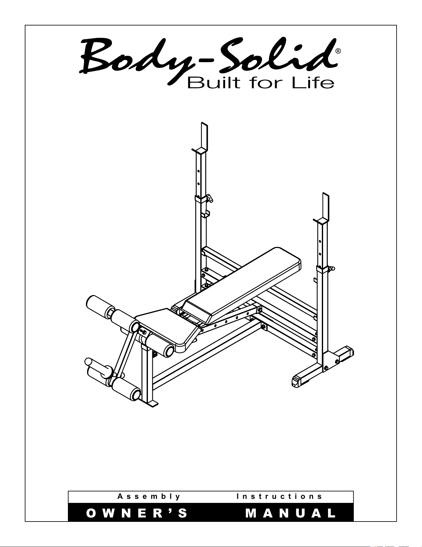
&
Assembly Instructions
OWNER’S MANUAL
V. GDIB46LB-20240408
GDIB46LB
Warning, Safety & Maintenance
2
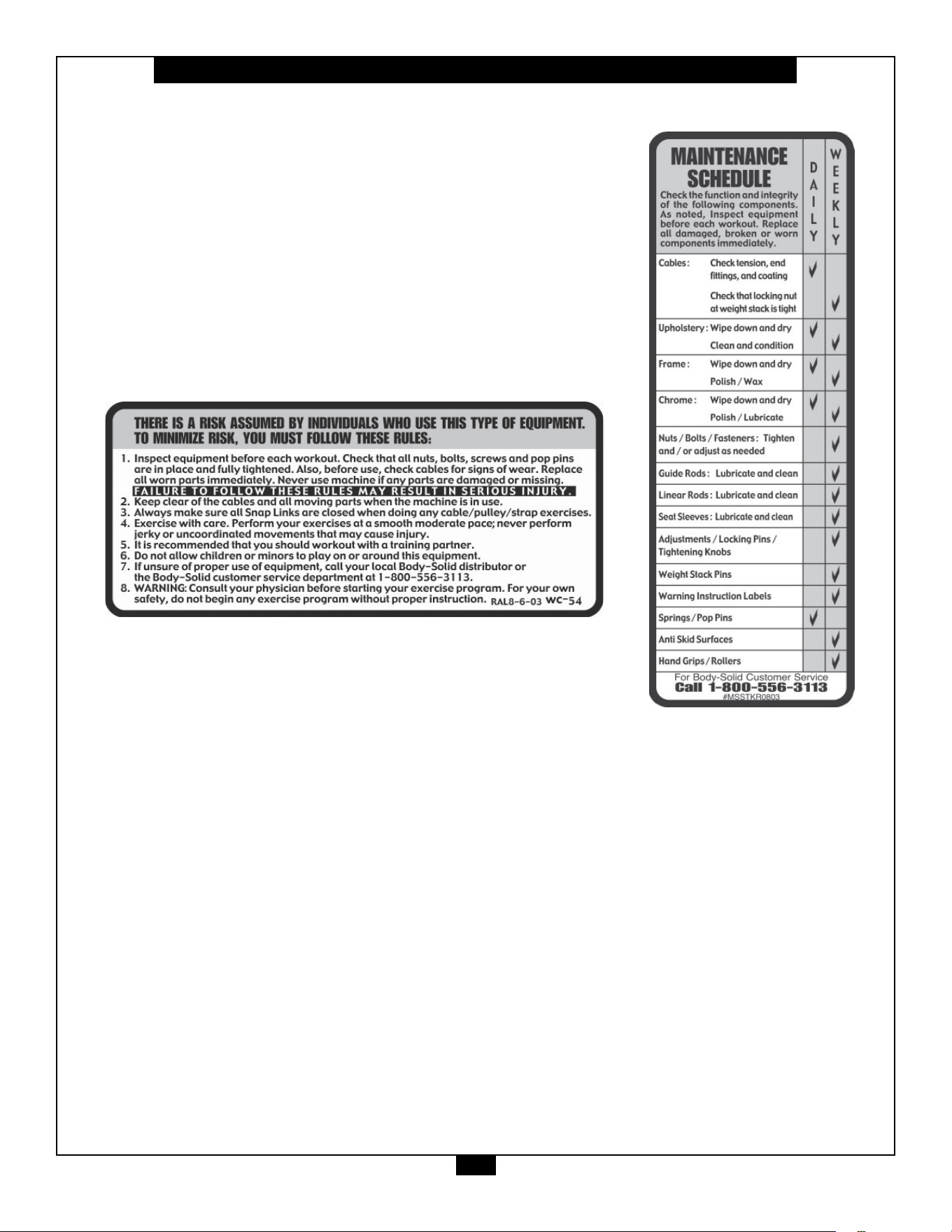
Be sure that all users carefully read and understand all
warning, safety and maintenance labels on the machine
before each use. Failure to do so may result in death or
serious injury.
It is imperative that you retain this Owner’s Manual and be
sure all warning labels are legible and intact. Replacement
Owner’s Manuals and warning labels are available from your
local Body-Solid dealer.
If you have any questions about the operation, set up or
maintenance of this machine please call our customer service
department at 1 (800) 556-3113.
#DWRULE-4
#DWRULE-4

Table of Contents
3
• SAFETY INSTRUCTIONS.............................. PAGE 4
• PREPARATION............................................... PAGE 5
• HARDWARE ILLUSTRATION......................... PAGE 6
• PART / HARDWARE LIST............................... PAGE 10
• ASSEMBLY INSTRUCTIONS......................... PAGE 12
• EXPLODED VIEW.......................................... PAGE 21
• CONTACT PAGE............................................ PAGE 22

Important Safety Instructions
4
Beforebeginninganytnessprogram,youshouldobtainacompletephysicalexaminationfromyourphysician.
Il est conseille de subir un examen medical complet avant d’entreprendre tout programme d’exercise.
Si vous avez des etourdissements ou des faiblesses, arretez les exercices immediatement.
Antes de comenzar cualquier programma de ejercicios, deberias tener un examen sico con su doctor.
When using exercise equipment, you
should always take basic precautions,
including the following:
m ReadallinstructionsbeforeusingtheGDIB46LB.
Theseinstructionsarewrittentoensureyoursafety
andtoprotecttheunit.
m Do not remove any safety labels from the
machine.
m Donotallowchildrenonorneartheequipment.
m Usetheequipmentonlyforitsintendedpurpose
asdescribedinthisguide.Donotuseaccessory
attachmentsthatarenotrecommendedbythe
manufacturer.Suchattachmentsmightcause
injuries.
m Wearproperexerciseclothingandshoesforyour
workout,nolooseclothing.
m Keephands,limbs,looseclothing,andlonghairwell
outofthewayofallmovingparts.
m Usecarewhengettingonorotheunit.
m Donotoverexertyourselforworktoexhaustion.
m Ifyoufeelanypainorabnormalsymptoms,stop
yourworkoutimmediatelyandconsultyour
physician.
m Neveroperateunitwhenithasbeendroppedor
damaged.Returntheequipmenttoaservice
centerforexaminationandrepair.
m Neverdroporinsertobjectsintoanyopeningin
theequipment.
m Alwayschecktheunitanditscablesbeforeeach
use.Makesurethatallfastenersandcablesare
secureandingoodworkingcondition.
m Donotusetheequipmentoutdoorsornearwater.
Personal Safety During Assembly
m Beforebeginningassembly,pleasetakethetime
toreadtheinstructionsthoroughly.
m Readeachstepintheassemblyinstructionsand
followthestepsinsequence.Donotskipahead.
Ifyouskipahead,youmaylearnlaterthatyou
havetodisassemblecomponentsandthatyou
mayhavedamagedtheequipment.
m Assembleandoperatethe GDIB46LBonasolid,
levelsurface.Locatetheunitafewfeetfromthe
wallsorfurnituretoprovideeasyaccess.
TheGDIB46LB isdesignedforyourenjoyment.By
followingtheseprecautionsandusingcommonsense,
youwillhavemanysafeandpleasurablehoursof
healthfulexercisewithyourBody-SolidF/I/DOlympic
BenchwithLegDeveloper.
Afterassembly,youshouldcheckallfunctionsto
ensurecorrectoperation.Ifyouexperienceproblems,
rstrechecktheassemblyinstructionstolocateany
possibleerrorsmadeduringassembly.Ifyouareunable
tocorrecttheproblem,callthedealerfromwhomyou
purchasedthemachineorcall1-800-556-3113forthe
dealernearestyou.
Obtaining Service
PleaseusethisOwner’sManualtomakesurethatall
partshavebeenincludedinyourshipment.When
orderingparts,youmustusethepartnumberand
descriptionfromthisOwner’sManual.Useonly
Body-Solidreplacementpartswhenservicingthis
machine.Failuretodosowillvoidyourwarrantyand
couldresultinpersonalinjury.
Forinformationaboutproductoperationorservice,
checkouttheocialBody-Solidwebsiteat
www.bodysolid.comorcontactanauthorized
Body-SoliddealeroraBody-Solidfactory-authorized
servicecompanyorcontactBody-Solidcustomer
serviceatoneofthefollowing:
Toll Free: 1-800-556-3113
Phone: 1-708-427-3555
Fax: 1-708-427-3556
Hours: M-F 8:30-5:00 CST
E-Mail: [email protected]
Or write to: Body-Solid, Inc.
Service Department
1900 S. Des Plaines Ave.
Forest Park, IL 60130 USA
Retain this Owner’s Manual for future
reference. If you need to order replacement
parts please be prepared to provide the
following information when contacting us so
that we can assist you better.
1. Model Number
2. Place of Purchase
3. Serial Number (S/N)
4. Part # and Description
Preparation
5
ThankyouforpurchasingtheGDIB46LB.ThisProductispartoftheBody-Solidlineofqualitystrengthtraining
machines,whichletsyoutargetspecicmusclegroupstoachievebettermuscletoneandoverallbody
conditioning. To maximize your use of the equipment please study this Owner’sManual thoroughly.
Body-Solidcontinuallyseekswaystoimprovetheperformance,specicationsandproductmanualsinordertoensurethatonly
superiorproductsarereleasedfromourfactories.Pleasetakethetimetocarefullyreadthroughthismanualthoroughly.Instructions
containedinthisdocumentarenotintendedtocoveralldetailsorvariationspossiblewithBody-Solidequipment,ortocoverevery
contingencythatmaybemetinconjunctionwithinstallation,operation,maintenanceortroubleshootingoftheequipment.Even
thoughwehavepreparedthismanualwithextremecare,neitherthepublishernortheauthorcanacceptresponsibilityforanyerrors
in,oromissionfrom,theinformationgiven.Shouldadditionalinformationberequired,orshouldsituationsarisethatarenotcovered
bythismanual,themattershouldbedirectedtoyourlocalBody-Solidrepresentative,ortheServiceDepartmentatBody-SolidInc.
inForestPark,Illinois.
Required Tools
Thebasictoolsthatyoumustobtainbeforeassembling
theGDIB46LBincludebutarenotlimitedto:
m StandardWrenchSet
m MetricWrenchSet
m AdjustableWrench
Installation Requirements
Followtheseinstallationrequirementswhenassembling
theGDIB46LB:
SetuptheGDIB46LBonasolid,atsurface.Asmooth,
atsurfaceunderthemachinehelpskeepitlevel.A
levelmachinehasfewermalfunctions.
Provideamplespacearoundthemachine.Open
spacearoundthemachineallowsforeasieraccess.
Insertallboltsinthesamedirection.Foraesthetic
purposes,insertallboltsinthesamedirectionunless
specied(intextorillustrations)todootherwise.
Leaveroomforadjustments.Tightenfastenerssuchas
bolts,nuts,andscrewssotheunitisstable,butleave
roomforadjustments.Donotfullytightenfasteners
untilinstructedintheassemblystepstodoso.
Fill out and mail the warranty card.
Assembly Tips
Readall“Notes”oneachpagebeforebeginningeach
step.
WhileyoumaybeabletoassembletheGDIB46LBusing
theillustrationsonly,importantsafetynotesandother
tipsareincludedinthetext.
Somepiecesmayhaveextraholesthatyouwillnotuse.
Useonlythoseholesindicatedintheinstructionsand
illustrations.
NOTE: Withsomanyassembledparts,proper
alignmentandadjustmentiscritical.While
tighteningthenutsandbolts,besuretoleave
roomforadjustments.
CAUTION: Obtainassistance!Ifyoufeellikeyoucan’t
assembletheGDIB46LBbyyourselfthendo
notattempttodosoasthiscouldresultin
injury.Reviewtheinstallationrequirements
beforeproceedingwiththefollowingsteps.
YourS/N#can
befoundhere
↑
45
6
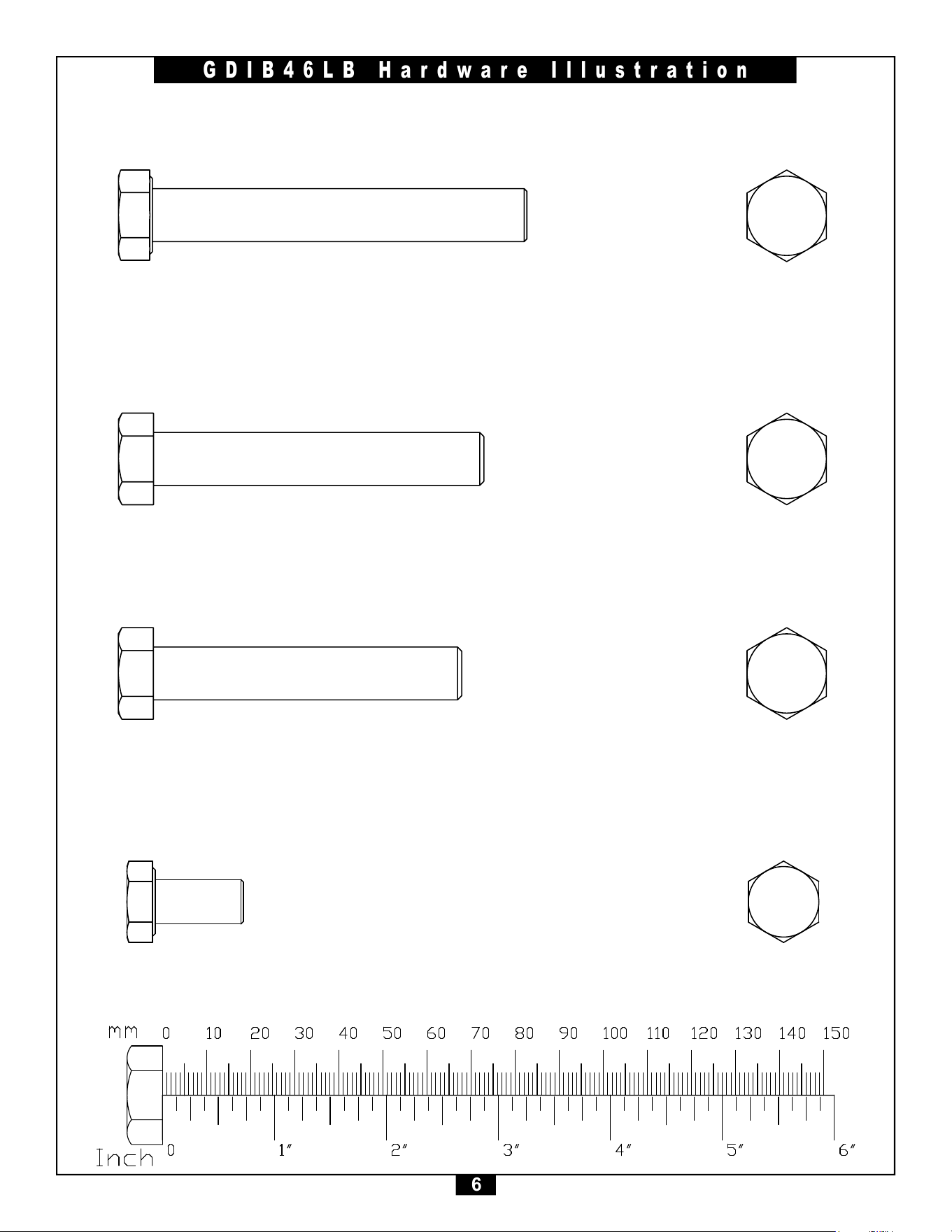
GDIB46LB Hardware Illustration
Part#1 M12x85mmHEXHEADBOLT QTY. 1
Part#2 M12x75mmHEXHEADBOLT QTY. 6
Part#3 M12x70mmHEXHEADBOLT QTY. 1
Part#4 M10x20mmHEXHEADBOLT QTY. 12
45
7
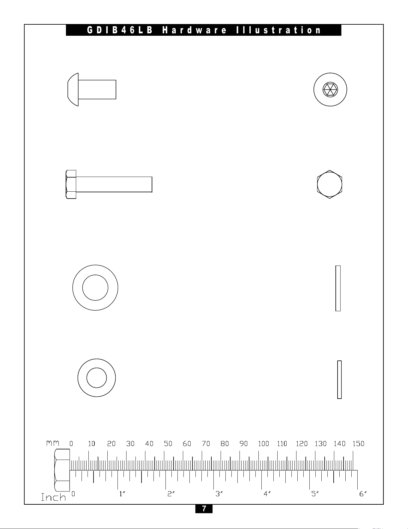
GDIB46LB Hardware Illustration
Part#6 M8x40mmHEXHEADBOLT QTY. 10
Part#5 M10x20mmBUTTONHEADCAPSCREW QTY. 1
Part#7 M12 FLAT WASHER QTY. 16
Part#8 M10 FLAT WASHER QTY. 12
45
8
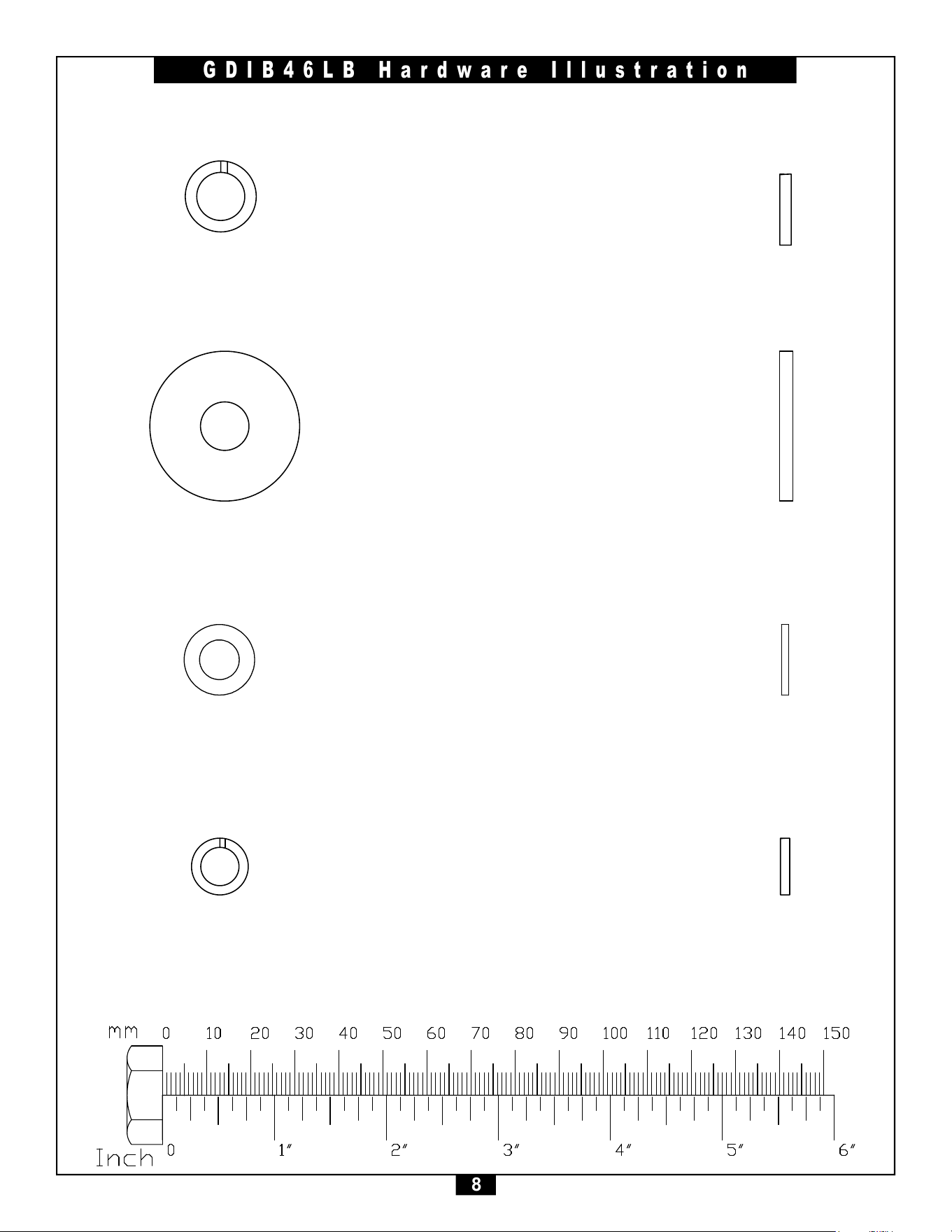
GDIB46LB Hardware Illustration
Part#10 M10 LARGE WASHER QTY. 1
Part#9 M10 LOCK WASHER QTY. 1
Part#12 M8 LOCK WASHER QTY. 10
Part#11 M8 FLAT WASHER QTY. 10
45
9
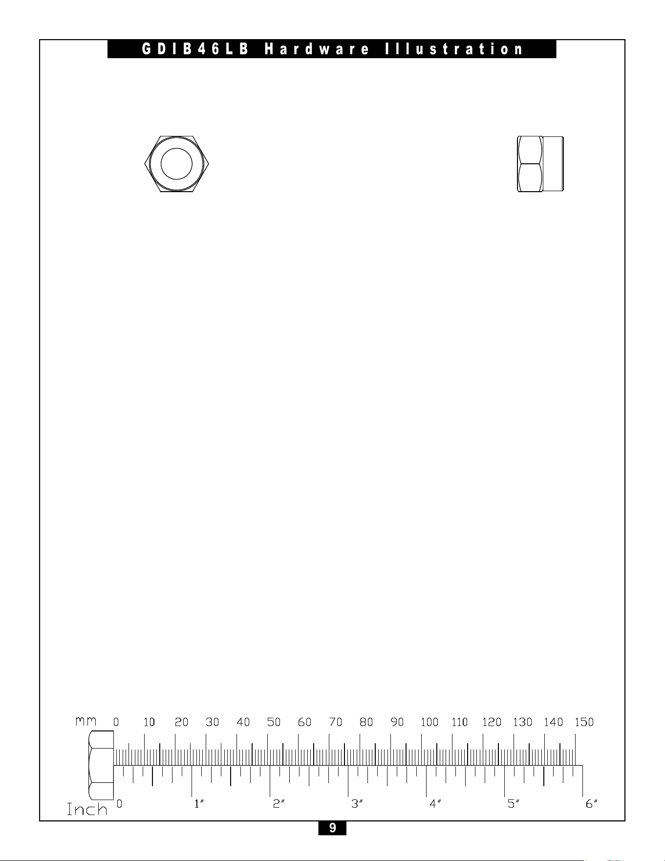
GDIB46LB Hardware Illustration
Part#13 M12 NYLON LOCK NUT QTY. 8

10
GDIB46LB Parts &Hardware List
Part# Qty Description
A
B
C
D
E
F
G
H
J
K
L
M
N
P
Q
R
1
2
3
4
5
6
7
8
9
10
11
12
13
14
15
16
17
18
1
2
1
1
1
1
1
2
1
2
2
1
1
3
3
1
1
6
1
12
1
10
16
12
1
1
10
10
8
3
1
1
3
2
FRONT BASE FRAME
SIDE BASE FRAME
LOWER MIDDLE FRAME
RIGHT UPRIGHT
UPPER MIDDLE FRME
LEFT UPRIGHT
BACK FRAME SUPPORT
ADJUSTABLE UPRIGHT
SLIDER CARRIAGE
SEAT FRAME
BACK FRAME
HEIGHT ADJUSTMENT FRAME
PIVOT FRAME
FOAM ROLLER BAR
STEEL BRACKET C-C 100mm
WEIGHT HORN
M12x85mmHEXHEADBOLT
M12x75mmHEXHEADBOLT
M12x70mmHEXHEADBOLT
M10x20mmHEXHEADBOLT
M10x20mmBUTTONHEADCAPSCREW
M8x40mmHEXHEADBOLT
M12 FLAT WASHER
M10 FLAT WASHER
M10 LOCK WASHER
M10 LARGE WASHER
M8 FLAT WASHER
M8 LOCK WASHER
M12 NYLON LOCK NUT
PLASTICBUSHING,55x55mm
TURN & LOCK POP PIN
THREADED STUD KNOB
T-HANDLE TURN & LOCK POP PIN
PLASTICBUSHING,60x60mm

Part# Qty Description
11
GDIB46LB Parts &Hardware List
Part# Qty Description
19
20
21
22
23
24
25
26
27
28
29
30
31
32
1
4
4
5
2
1
6
6
1
1
1
1
1
1
T-HANDLE PULL PIN
PLASTICENDCAP,25x25mm
FOOTCAP,50x50mm
PLASTICENDCAP,38x38mm
METALBUSHING,ø20xø12.6x10mm
QUICK RELEASE PULL PIN
FOAMROLLER,ø90x185mm
PLASTICENDCAP,ø60mm
ROUNDDOMEPLASTICENDCAP,ø50mm
PLASTICENDCAP,45x45mm
RUBBERBUMPER,ø35xø25x35mm
RUBBERRING,ø85xø50x10mm
SEAT PAD
BACK PAD

12
STEP
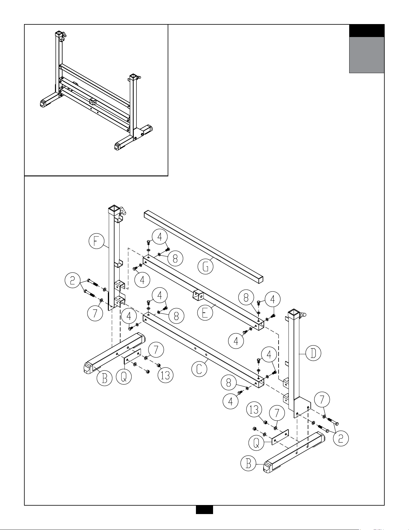
1
Be careful to assemble all components
in the sequence they are presented.
NOTE:
Finger tighten all hardware in this step. DO NOT wrench tighten until instructed.
Some components may be pre-assembled. Nylon lock nuts will not fully screw onto
bolts, they must be wrench tightened to fully go on.
1A. AttachRightUpright(D) toSideBaseFrame(B) using:
2 - (#2) M12x75mm Hex Head Bolt
4 - (#7) M12 Flat Washer
2 - (#13) M12 Nylon Lock Nut
1 - (Q) Steel Bracket
1B. AttachLeftUpright(F) toSideBaseFrame(B) using:
2 - (#2) M12x75mm Hex Head Bolt
4 - (#7) M12 Flat Washer
2 - (#13) M12 Nylon Lock Nut
1 - (Q) Steel Bracket
1C. AttachLowerMiddleFrame(C) & UpperMiddleFrame(E) to
RightUpright(D) using:
6 - (#4) M10x20mm Hex Head Bolt
6 - (#8) M10 Flat Washer
1D. AttachLowerMiddleFrame(C) & UpperMiddleFrame(E) to
LeftUpright(F) using:
6 - (#4) M10x20mm Hex Head Bolt
6 - (#8) M10 Flat Washer
1E. PutBackFrameSupport(G)betweenUprights(D & F).
STEP
1
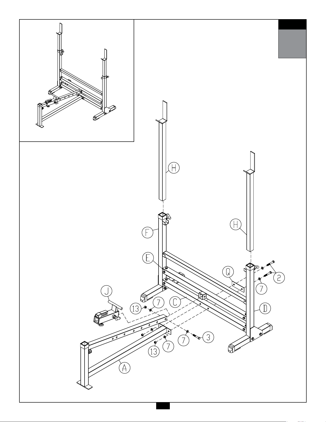
AboveshowsStep1assembledandcompleted.
13

14
STEP
2
Be careful to assemble all components
in the sequence they are presented.
NOTE:
Wrench tighten ALL hardware at the end of STEP 2B. Some components may be
pre-assembled. Nylon lock nuts will not fully screw onto bolts, they must be wrench
tighten to fully go on.
2A. lnsertSlidingCarriage(J) ontoFrontMainFrame(A)
2B. AttachFrontMainFrame(A) toLower&UpperMiddelFrames
(C & E) using:
2 - (#2) M12x75mm Hex Head Bolt
1 - (#3) M12x70mm Hex Head Bolt
6 - (#7) M12 Flat Washer
3 - (#13) M12 Nylon Lock Nut
1 - (Q) Steel Bracket
2C. lnsertAdjustableUprights(H) intoLeft&RightUpright(F & D).
STEP
2
AboveshowsStep2assembledandcompleted.
15

16
STEP
3
Be careful to assemble all components
in the sequence they are presented.
NOTE:
Wrench tighten ALL hardware at the end of STEP 3E. Some components may be
pre-assembled. Nylon lock nuts will not fully screw onto bolts, they must be wrench
tighten to fully go on.
3A. lnsertSeatFrames(K) ontoSlidingCarriage(J).
3B. AttachSeatPad(#31) toSeatFrames(K) using:
4 - (#6) M8x40mm Hex Head Bolt
4 - (#11) M8 Flat Washer
4 - (#12) M8 Lock Washer
3C. T-HandlePullPin(#19) istobeusedforSeatAngleAdjustment.
3D. lnsertBackFrames(L) ontoSlidingCarriage(J).
3E. AttachBackPad(#32) toBackFrames(L) using:
6 - (#6) M8x40mm Hex Head Bolt
6 - (#11) M8 Flat Washer
6 - (#12) M8 Lock Washer
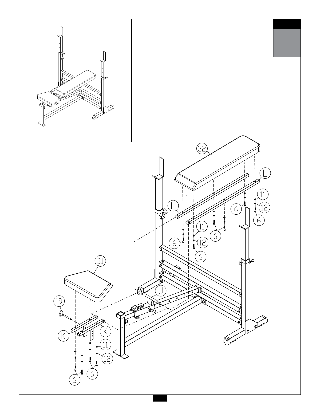
STEP
3
AboveshowsStep3assembledandcompleted.
17

d
18
STEP
4
Be careful to assemble all components
in the sequence they are presented.
NOTE:
Wrench tighten ALL hardware at the end of STEP 4B. Some components may be
pre-assembled. Nylon lock nuts will not fully screw onto bolts, they must be wrench
tighten to fully go on.
4A. InsertHeightAdjustmentFrame(M)intoFrontBaseFrame(A).
4B. AttachPivotFrame(N) toHeightAdjustmentFrame(M) using:
1 - (#1) M12x85mm Hex Head Bolt
2 - (#7) M12 Flat Washer
1 - (#13) M12 Nylon Lock Nut
4C. InsertFoamRollerBars(K)intoHeightAdjustmentFrame(M)
& PivotFrame(N).
4D. InstallFoamRollers(#25)&PlasticEndCaps(#29)ontoeach
FoamRollerBars(K).
4E. AttachWeightHorn(R) toPivotFrame(N) using:
1 - (#1) M10x20mm Button Head Cap Screw
1 - (#9) M10 Lock Washer
1 - (#10) M10 Large Washer
4F. InsertRoundDomePlasticEndCap(#27)intoWeightHorn(R).
4G. InsertRubberRing(#30)ontoWeightHorn(R).
4G. QuickReleasePullPin(#24) istobeusedforLockingPivot
Frame(N)fromrotating.
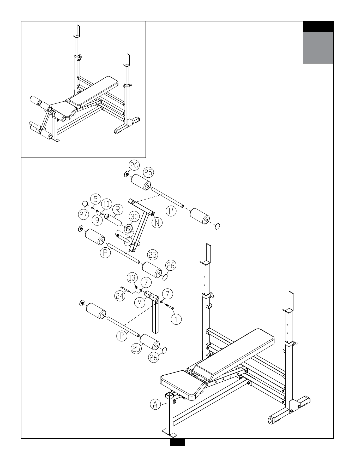
STEP
4
AboveshowsStep4assembledandcompleted.
19

45
20
Notes
21
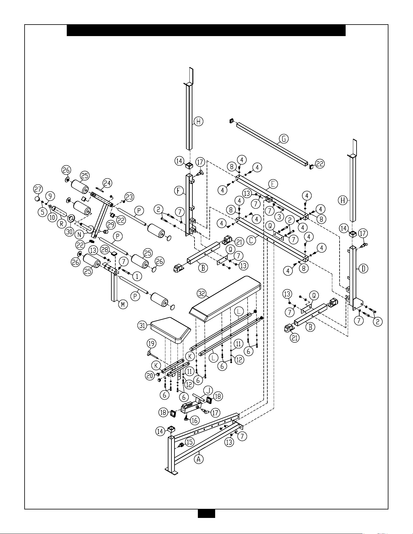
GDIB46LB Exploded View

1900S.DesPlainesAve.
ForestPark,IL60130
Phone:(708)427-3555
Fax:(708)427-3556
Hours:M-F8:30-5:00CST
www.bodysolid.com
Copyright 2009. Body-Solid. All rights reserved. Body-Solid reserves the right to change design and specications when we feel it will improve the product.
Body-Solid machines maintain several patented and patent pending features and designs. All rights reserved on all design patents and utility patents.
PLEASE WRITE YOUR SERIAL NUMBER IN THE BOXES BELOW
S/N# 000766-��-��-����-����
GDIB46LB