BFOB10B
O W NER’ S MANUAL
V. BFOB10B-20240816

2
Thank you for purchasing the Best Fitness BFOB10B. This gym is part of the Best Fitness quality strength
training machines, which lets you target specific muscle groups to achieve better muscle tone and overall body
condition-ing.
To maximize your use of the equipment please study this Owner’s Manual thoroughly.
Unpacking the Equipment
The BFOB10B is carefully tested and inspected
before shipment. We have shipped the unit in several
pieces that require assembly. Ask for assistance
during the assembly process.
Carefully unpack the boxes and lay the pieces on
the floor near the area where you plan to use the
equipment.
Be careful to assemble all components in the
sequence presented in this guide.
If any items are missing, contact the dealer from whom
you purchased the unit or call 1-800-556-3113 for
the dealer nearest you.
BEFORE YOU BEGIN
Body-Solid continually seeks ways to improve the performance, specifications and product manuals in order to
ensure that only superior products are released from our factories. Please take the time to carefully read through this
manual thoroughly. Instructions contained in this document are not intended to cover all details or variations possible
with Body-Solid equipment, or to cover every contingency that may be met in conjunction with installation, operation,
maintenance or troubleshooting of the equipment. Even though we have prepared this manual with extreme care, nei-
ther the publisher nor the author can accept responsibility for any errors in, or omission from, the information given.
Should additional information be required, or should situations arise that are not covered by this manual, the matter
should be directed to your local Body-Solid representative, or the Service Department at Body-Solid Inc. in Forest
Park, Illinois.
Any Questions?
Call (800) 556-3113

3
IMPORTANT SAFETY INSTRUCTIONS
Before beginning any fitness program, you should obtain a complete physical examination from your physician.
Il est conseille de subir un examen medical complet avant d’entreprendre tout programme d’exercise. Si vous
avez des etourdissements ou des faiblesses, arretez les exercices immediatement.
Antes de comenzar cualquier programma de ejercicios, deberias tener un examen fisico con su doctor.
When using exercise equipment, you
should always take basic precautions,
including the following:
• Read all instructions before using the BFOB10B
These instructions are written to ensure your safety
and to protect the unit.
• Do not allow children on or near the equipment.
• Use the equipment only for its intended purpose as
described in this guide. Do not use accessory
attachments that are not recommended by the
manufacturer. Such attachments might cause injuries.
• Wear proper exercise clothing and shoes for your
workout, no loose clothing.
• Use care when getting on or off the unit.
• Do not overexert yourself or work to exhaustion.
• If you feel any pain or abnormal symptoms, stop your
workout immediately and consult your physician.
• Never operate unit when it has been dropped or
damaged. Return the equipment to a service center
for examination and repair.
• Never drop or insert objects into any opening in the
equipment.
• Always check the unit before each use. Make sure
that all fasteners are secure and in good working
condition.
• Do not use the equipment outdoors or near water.
Personal Safety During Assembly
• It is strongly recommended that a qualified dealer
assemble the equipment. Assistance is required.
• Before beginning assembly, please take the time to
read the instructions thoroughly.
• Read each step in the assembly instructions and
follow the steps in sequence. Do not skip ahead. If
you skip ahead, you may learn later that you have to
disassemble components and that you may have
damaged the equipment.
• Assemble and operate the BFOB10B on a solid, level
surface. Locate the unit a few feet from the walls or
furniture to provide easy access.
The BFOB10B is designed for your enjoyment. By
following these precautions and using common sense,
you will have many safe and pleasurable hours of
healthful exercise with your Best Fitness BFOB10B.
After assembly, you should check all functions to
ensure correct operation. If you experience problems,
first recheck the assembly instructions to locate any
possible errors made during assembly. If you are unable
to correct the problem, call the dealer from whom
you purchased the machine or call 1-800-556-3113
for the dealer nearest you.
Obtaining Service
Please use this Owner’s Manual to make sure that all
parts have been included in your shipment. When
ordering parts, you must use the part number and
description from this Owner’s Manual. Use only
Best Fitness replacement parts when servicing this
machine. Failure to do so will void your warranty and
could result in personal injury.
For information about product operation or service,
go to www.bestfitness.com or contact an authorized
Best Fitness dealer or a Best Fitness factory-authorized
service company or contact Best Fitness customer
service at one of the following:
Toll Free: 1-800-556-3113
Phone: 1-708-427-3555
Fax: 1-708-427-3556
Hours: M-F 8:30-5:00 CST
E-Mail: [email protected]
Or write to: Best Fitness
Service Department
1900 S. Des Plaines Ave.
Forest Park, IL 60130 USA
Retain this Owner’s Manual for future
reference. Part numbers are required when
ordering parts.

4
SAFETY GUIDELINES
Successful resistance training programs have one prominent feature in common...safety. Resistance
training has some inherent dangers, as do all physical activities. The chance of injury can be greatly
reduced or completely removed by using correct lifting techniques, proper breathing, maintaining
equipment in good working condition, and by wearing the appropriate clothing.
1. It is highly recommended that you consult your physician before beginning any exercise
program. This is especially important for individuals over the age of 35, or persons with
pre-existing health problems.
2. Always warm up before starting a workout. Try to do a total body warm up before you start. It is
especially important to warm up the specific muscle groups you are going to be using. This can
be as simple as performing a warm up set of high repetitions and light weight for each exercise.
3. Use proper form. Focus on only working the muscle groups intended for the exercise you are
doing. If there is strain elsewhere, you may need to re-evaluate the amount of weight that is
involved with the lift. Keeping proper form also includes maintaining control through an entire
range of motion.
4. Breath properly. Inhale during the eccentric phase of the exercise, and exhale during the lifting,
or concentric phase. Never hold your breath during any part of an exercise.
5. Always wear the appropriate clothing and shoes when exercising. Wearing comfortable athletic
shoes with good support and loose fitting, breathable clothing will reduce the risk of injury.
6. Maintaining equipment in proper operating condition is of utmost importance for a safe
resistance training program. Pulleys and cables should be checked for wear frequently and
replaced as needed. Equipment should be lubricated as indicated by the manufacturer.
7. Read and study all warning labels on this machine. It is absolutely necessary that you
familiarize yourself and all others with the proper operation of this machine prior to use.
8. Keep hands, limbs, loose clothing and long hair well out of the way of all moving parts.
9. Do not attempt to lift more weight than you can control safely.
10. Inspect the machine daily for loose or worn parts. If a problem is found do not allow the
machine to be used until all parts are tightened or worn or defective parts are repaired or
replaced.
5
Assembly of the BFOB10B takes professional installers about 1/2 hour to complete. If this is the
first time you have assembled this type of equipment, plan on significantly more time.
PROFESSIONAL INSTALLERS ARE HIGHLY RECOMMENDED!
However, if you acquire the appropriate tools, obtain assistance, and follow the assembly steps
sequentially, the process will take time, but is fairly easy.
Assembly Tips
Read all “Notes” on each page before beginning each
step.
While you may be able to assemble the BFOB10B using
the illustrations only, important safety notes and other tips
are included in the text.
Some pieces may have extra holes that you will not use.
Use only those holes indicated in the instructions and il-
lustrations.
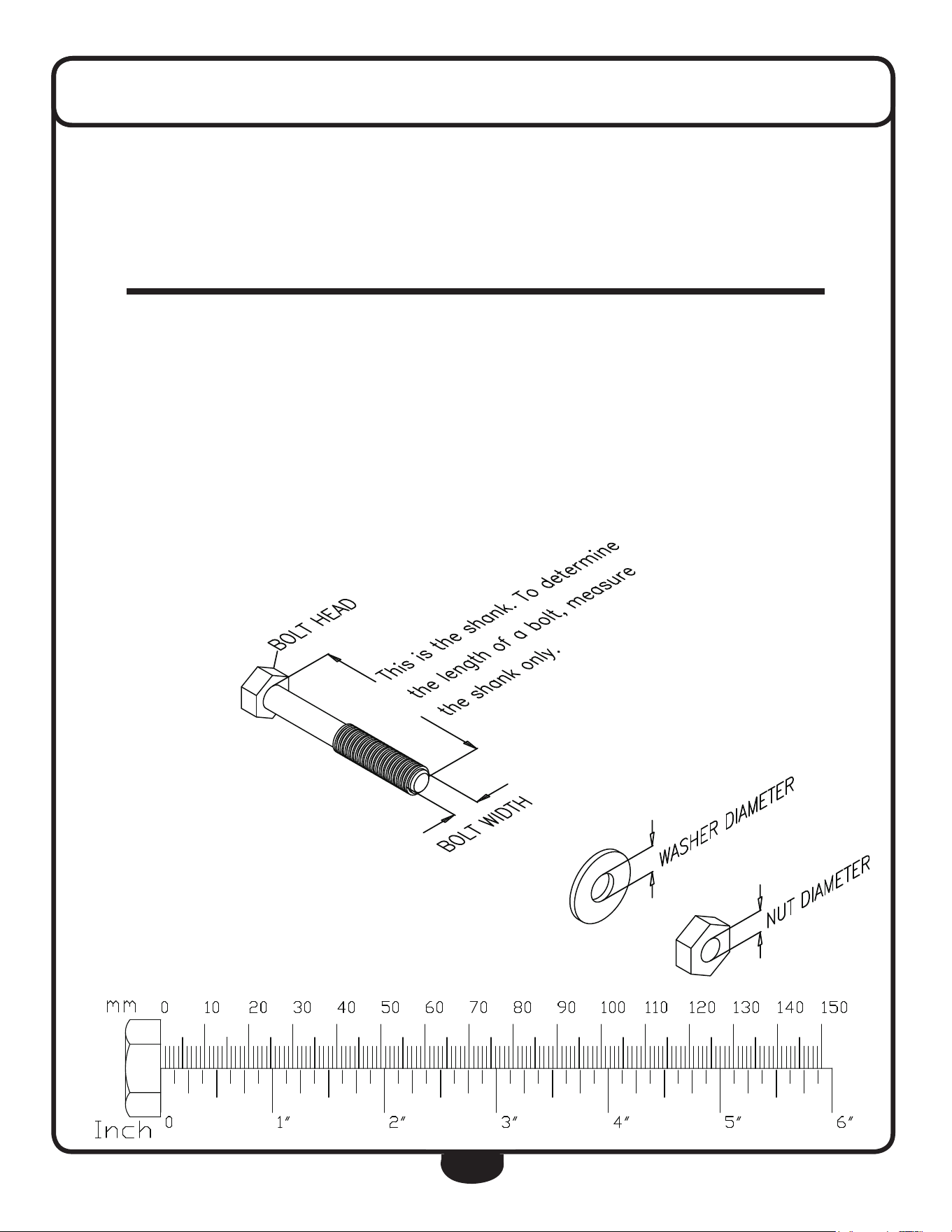
NOTE: To find out the length of a particular bolt, measure
its shank (the long, narrow part beneath the head).
Refer to the following diagram:
Do not fully tighten bolts until instructed to do so.
Note: After assembly, you should check all functions to ensure
correct operation. If you experience problems, first recheck
the assembly instructions to locate any possible errors made
during assembly.
If you are unable to correct the problem, call the dealer from
whom you purchased the machine or call 1-800-556-3113
for the dealer nearest you.
ASSEMBLY INSTRUCTIONS

6
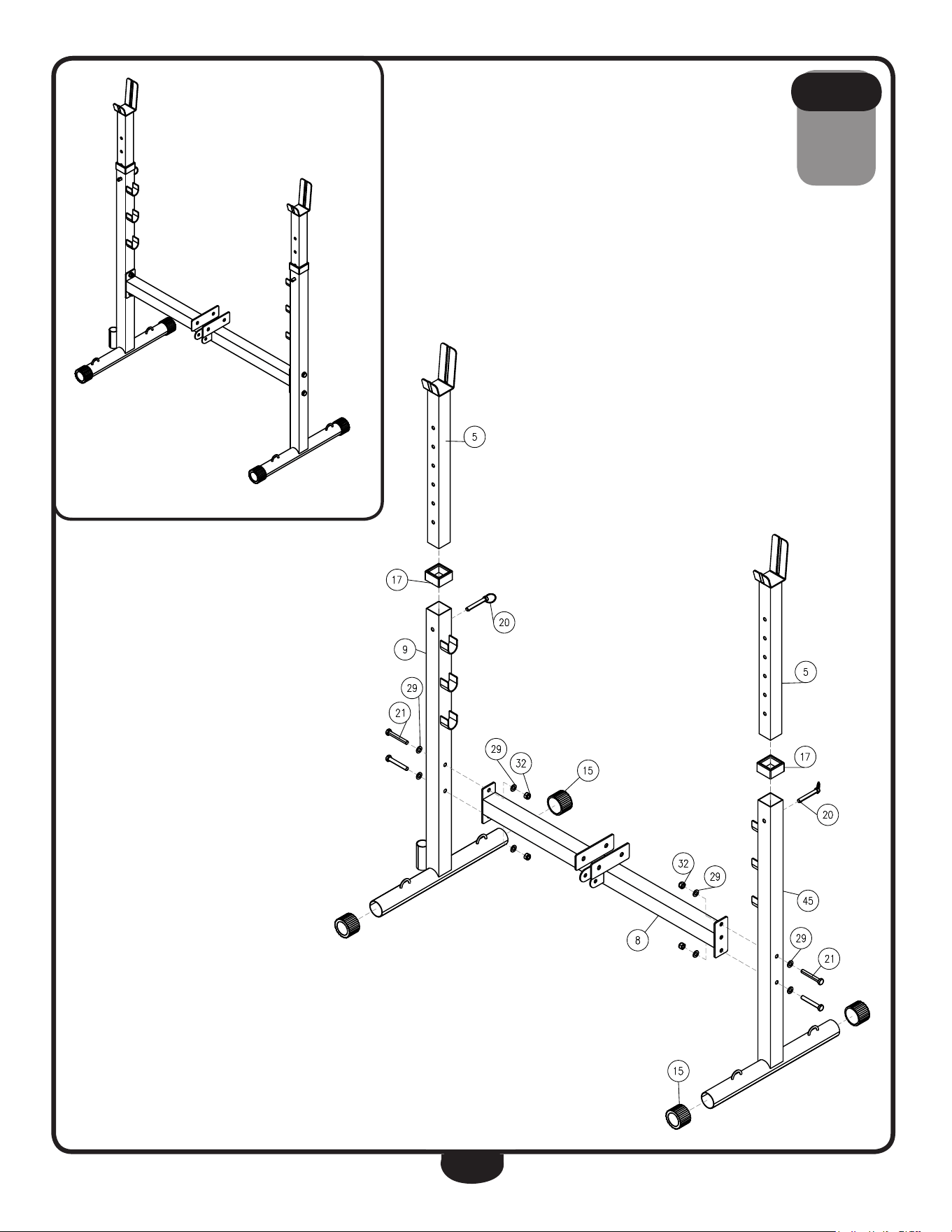
Be careful to assemble all components
in the sequence they are presented.
A. Insert Round End Caps (15) into Right Weight Support Frame (9) and Left Weight
Support Frame (45).
B. Assemble Right Weight Support Frame (9) and Weight Frame Cross Bar (8) by
using:
Two 21 (M10x70 hex head bolt)
Four 29 (M10 washer)
Two 32 (M10 nylon lock nut)
C. Assemble Left Weight Support Frame (45) and Weight Frame Cross Bar (8) by
using:
Two 21 (M10x70 hex head bolt)
Four 29 (M10 washer)
Two 32 (M10 nylon lock nut)
D. Insert End Cap (17) into Right Weight Support Frame (9) and Left Weight Support
Frame (45).
E. Insert Adjustable Booms (5) into Right Weight Support Frame (9) and Left Weight
Support Frame (45) as shown in the diagram. Secure the assembly using Pin (20).
STEP
1
7
STEP
1
Above shows STEP 1 assembled and completed.

8
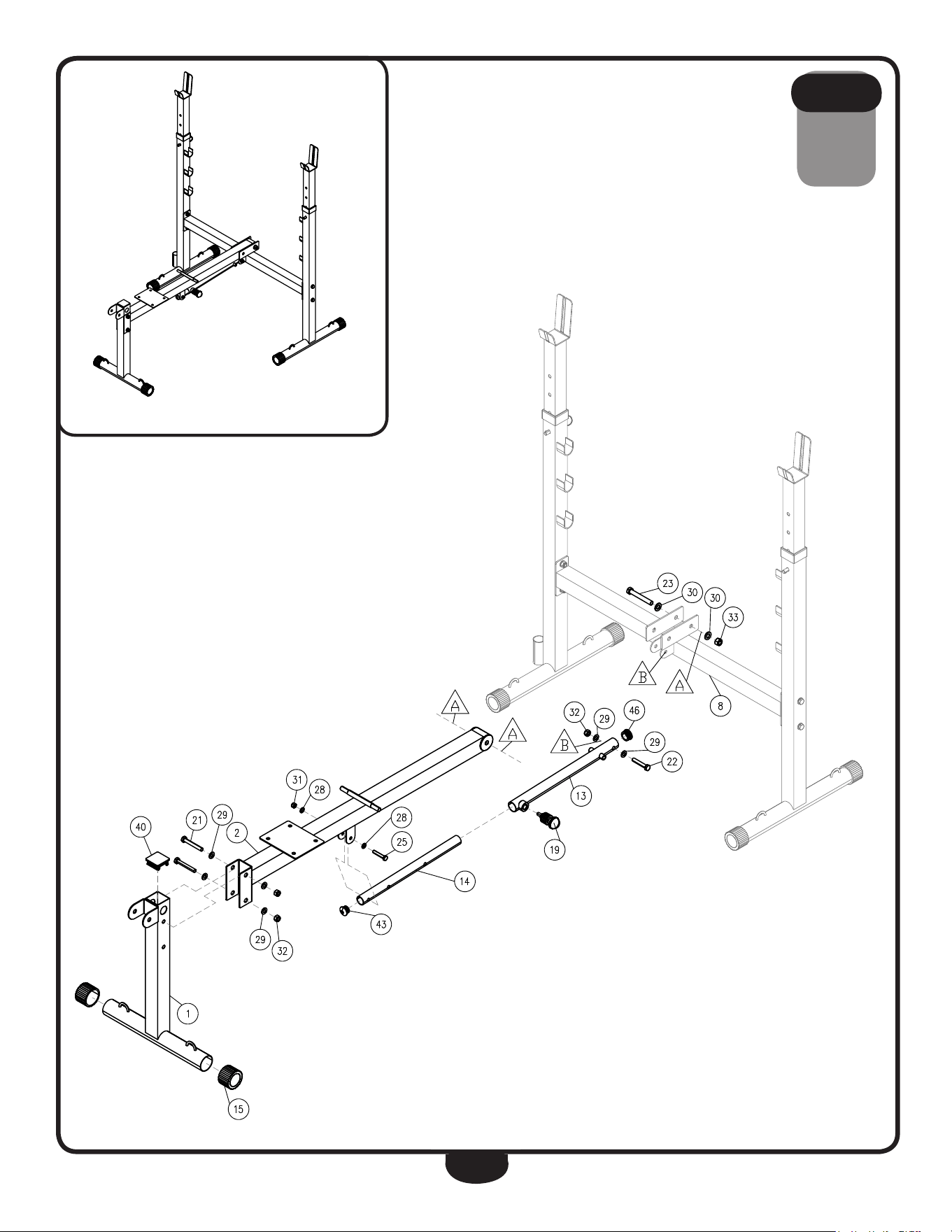
Be careful to assemble all components
in the sequence they are presented.
A. Connect Seat and Backrest Frame (2) to Weight Frame Cross Bar (8) at position
A
using:
One 23 (M12x85 hex head bolt)
Two 30 (M12 washer)
One 33 (M12 nylon lock nut)
B. Insert End Cap (40) into Leg Developer Frame (1) as shown.
Connect Leg Developer Frame (1) to Seat and Backrest Frame (2) using:
Two 21 (M10x70 hex head bolt)
Four 29 (M10 washer)
Two 32 (M10 nylon lock nut)
C. Insert Round End Cap (46) into Telescoping Lower Section (13).
D. Connect Telescoping Lower Section (13) to Weight Frame Cross Bar (8) at position
B
using:
One 22 (M10x55 hex head bolt)
Two 29 (M10 washer)
One 32 (M10 nylon lock nut)
E. Insert Round End Cap (43) into Telescoping Upper Section (14).
F. Insert Telescoping Upper Section (14) into Telescoping Lower Section (13) and secure
using (19).
G. Connect Telescoping Upper Section (14) to Backrest Frame (2) and secure using:
One 25 (M8x50 hex head bolt)
Two 28 (M8 washer)
One 31 (M8 nylon lock nut)
STEP
2
9
STEP
2
Above shows STEP 2 assembled and completed.

10
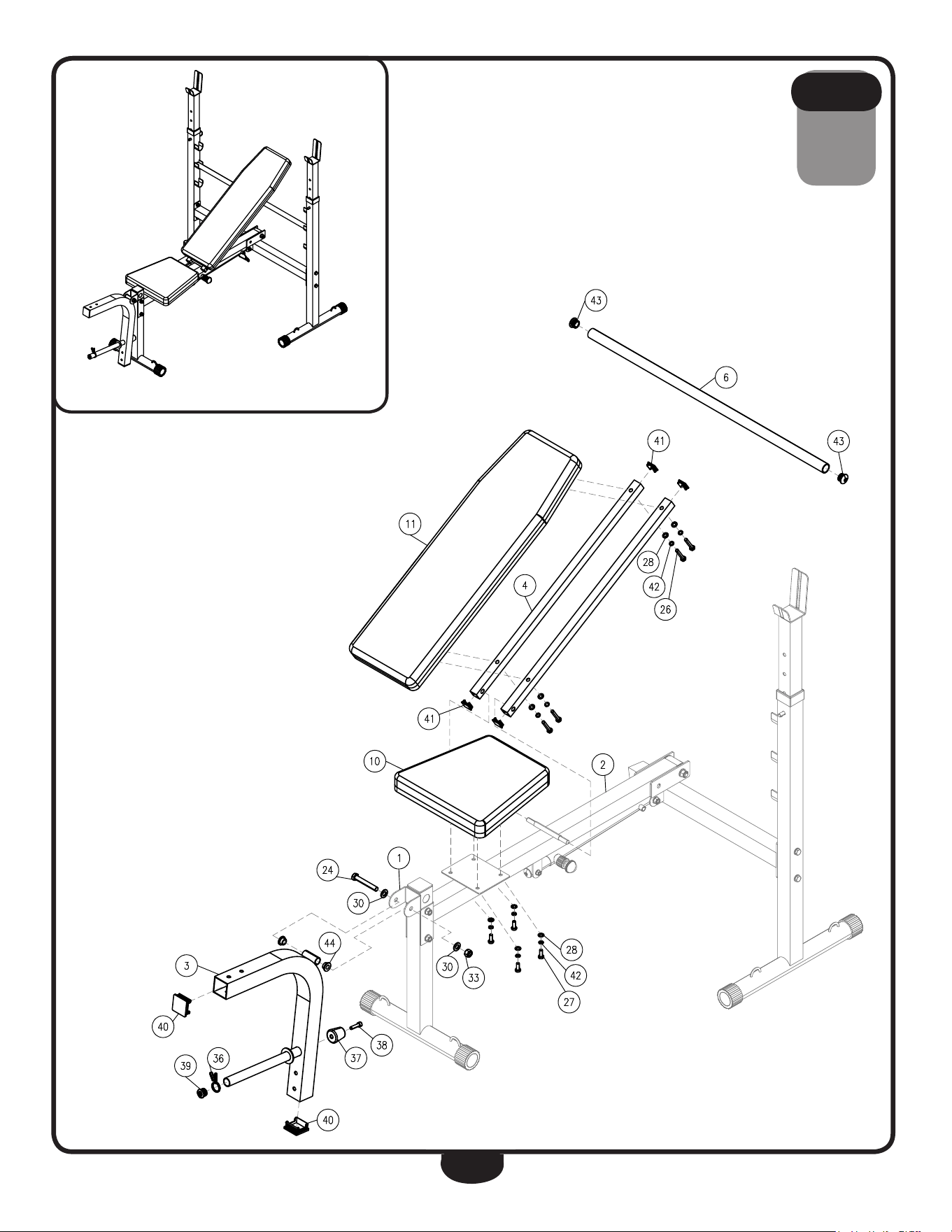
Be careful to assemble all components
in the sequence they are presented.
A. Insert Round End Caps (43) into Back Rest Support (6).
Install Back Rest Support (6) as shown in the diagram.
B. Insert four Square End Caps (41) into Back Pad Frame (4).
C. Connect Back Rest (11) to Back Pad Frame (4) using:
Four 26 (M8x45 hex head bolt)
Four 42 (M8 lock washer)
Four 28 (M8 washer)
NOTE: Make sure Back Pad Frame (4) is completely attached to the shaft on Seat
and Backrest Frame (2) while assembling.
D. Connect Seat Pad (10) to Seat and Backrest Frame (2) using:
Four 27 (M8x25 hex head bolt)
Four 42 (M8 lock washer)
Four 28 (M8 washer)
E. Insert Square End Caps (40) and Round End Cap (39) into Leg Developer Pivot
Frame (3).
F. Connect Leg Developer Pivot Frame (3) to Leg Developer Frame (1) using:
One 24 (M12x80 hex head bolt)
Two 30 (M12 washer)
One 33 (M12 nylon lock nut)
Two 44 (M12 Bushing)
G. Thread M8x30 Hex Head Bolt (38) into Leg Developer Pivot Frame (3) securing
Rubber Stopper (37).
H. Install M25 Spring Collar (36) onto the Weight Horn on Leg Developer Pivot Frame
(3).
STEP
3
11
STEP
3
Above shows STEP 3 assembled and completed.

12
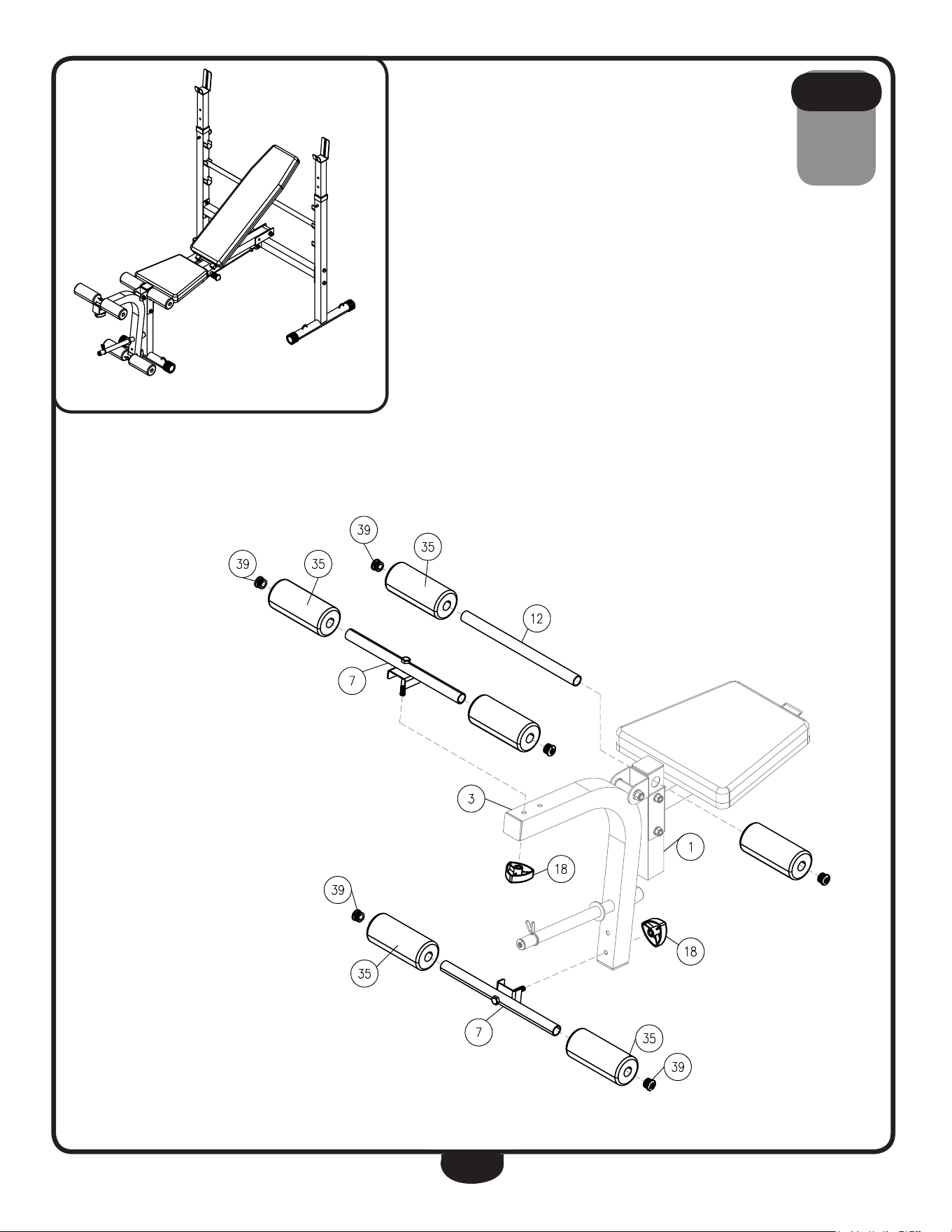
Be careful to assemble all components
in the sequence they are presented.
A. Slide Foam Roller Bar (12) through Leg Developer Frame (1) as shown.
B. Slide both Foam Rollers (35) onto Foam Roller Bar (12) and secure with Round
End Caps (39).
C. Connect both Foam Roller Bar Assemblies (7) to Leg Developer Pivot Frame (3)
by using:
Two 18 (M10 knob screw cap)
D. Slide Foam Rollers (35) onto both Foam Roller Bar Assemblies (7) and secure with
Round End Caps (39).
STEP
4
13
STEP
4
Above shows STEP 4 assembled and completed.

14
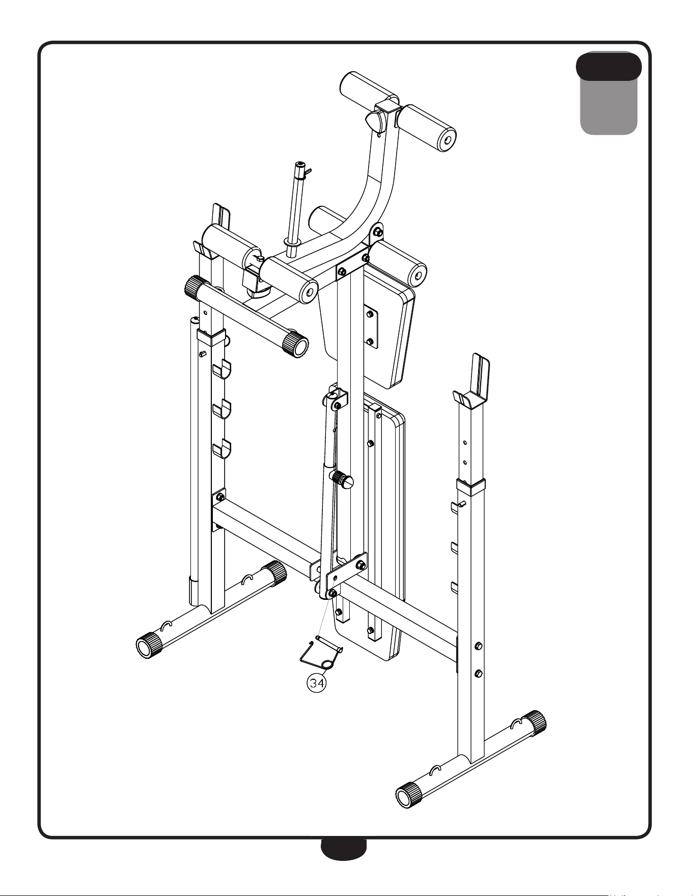
Folding and storing the BFOB10B.
To secure the BFOB10B in the folded position, insert Safety Pin (34) as shown in
the diagram.
S T E P
5
15
STEP
5
16
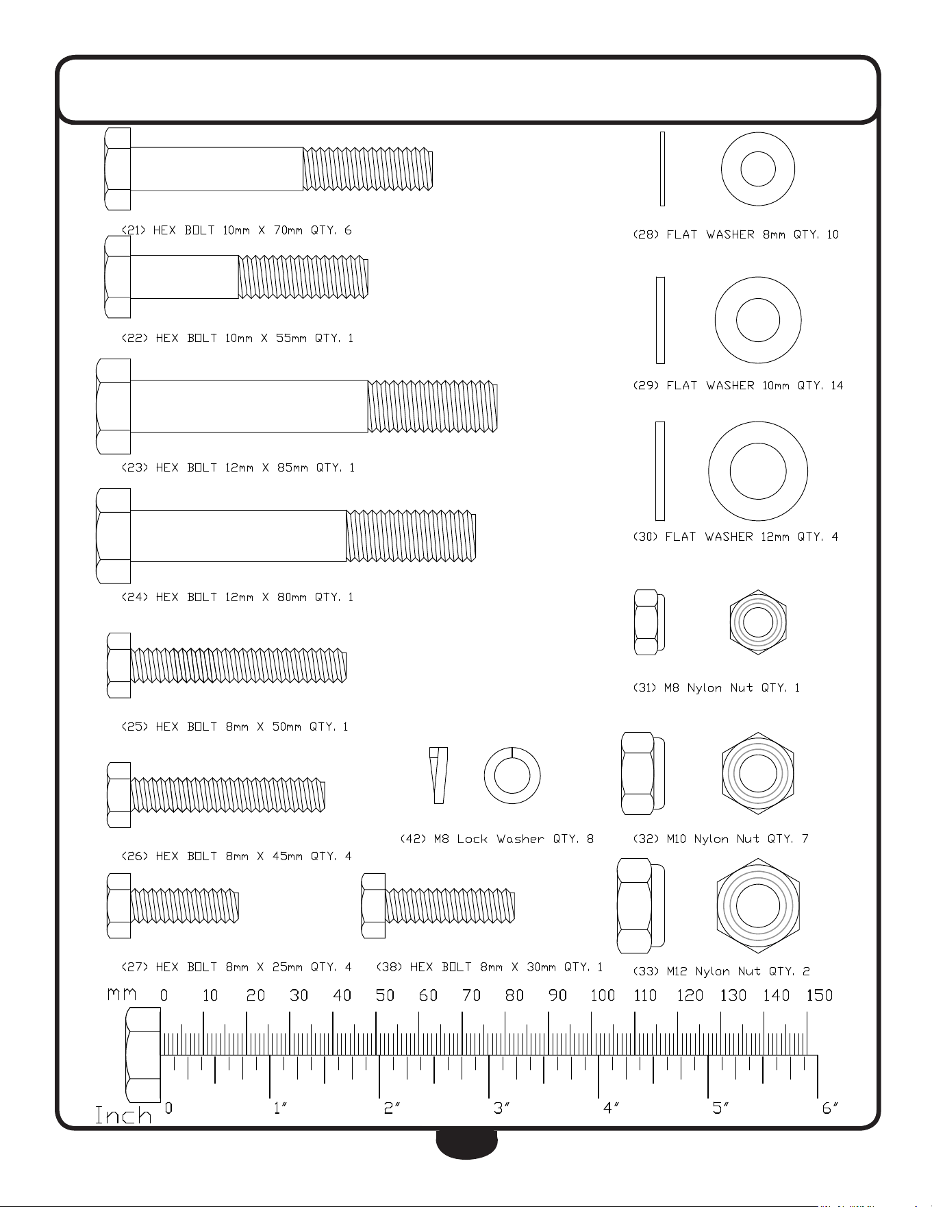
HARDWARE
(Actual Size Shown)

17
HARDWARE LIST
PART# QTY DESCRIPTION
1 1 Leg Developer Frame
2 1 Seat and Backrest Frame
3 1 Leg Developer Pivot Frame
4 2 Back Pad Frame
5 2 Adjustable Boom
6 1 Back Rest Support
7 2 Foam Roller Bar Assembly
8 1 Weight Frame Crossbar
9 1 Right Weight Support Frame
10 1 Seat Pad
11 1 Back Rest
12 1 Foam Roller Bar
13 1 Telescoping Lower Section
14 1 Telescoping Upper Section
15 6 M50 Round End Cap
16 2 M50x12.5x20 Rotating Axis
17 2 End Cap
18 2 M10 Knob Screw Cap
19 1 Ball Pop Pin
20 2 Pin
21 6 M10x70 Hex Head Bolt
22 1 M10x55 Hex Head Bolt
23 1 M12x85 Hex Head Bolt
24 1 M12x80 Hex Head Bolt
25 1 M8x50 Hex Head Bolt
26 4 M8x45 Hex Head Bolt
27 4 M8x25 Hex Head Bolt
28 10 M8 Washer
29 14 M10 Washer
30 4 M12 Washer
31 1 M8 Nylon Lock Nut
32 7 M10 Nylon Nut
33 2 M12 Nylon Nut
34 1 M10 Pin
35 6 M70x23x160 Foam Roller
36 1 M25 Spring Collar
37 1 Rubber Stopper
38 1 M8x30 Hex Head Bolt
39 7 M25 Round End Cap
40 3 M50x50 Square End Cap
41 4 M25x25 Square End Cap
42 8 M8 Lock Washer
43 3 M28 Round End Cap
44 2 M12 Bushing
45 1 Left Weight Support Frame
46 1 M32 Round End Cap
Part numbers are required when ordering parts.
18
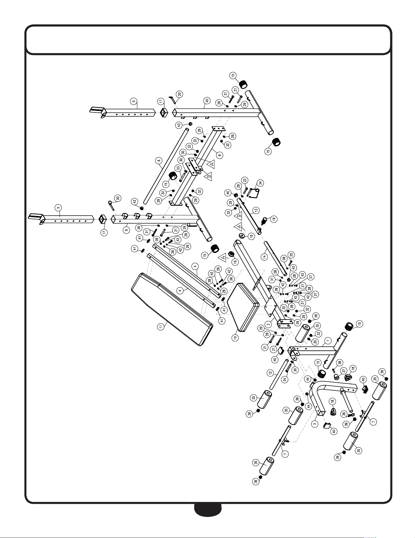
EXPLODED VIEW DIAGRAM

BFOB10B
S/N # 001442