SY288 LTE Cat.1 bis Module
Specification
Table of Contents
1. Overview
2. Specifications
3. RF Parameters
4. Pin Definition
1. Overview
SY288 is a low-power LTE CAT1 module supporting mainstream frequency bands worldwide. It
can be widely used in POS terminals, cloud speakers, IPC cameras, trackers, shared devices,
and other IoT product fields.
2. Specifications
Item
Specification
Chip Model
EC718PM
Frequency Bands
FDD BAND:
1/2/3/4/5/7/8/12/13/14/17/18/19/20/25/26/28/66/71
TDD BAND: 34/38/39/40/41
Interface
USB, UART, I2C, SPI
SIM Interface
Dual SIM single standby
USIM1: 1.8V/3V cards; USIM2: 1.8V cards
Dimensions
17.7 x 15.8 x 2.4 mm
Operating Temperature
-30C to +75C
Operating Voltage
3.3V to 4.3V, typical 3.8V
Protocol Standard
Max 3GPP Rel-14 Cat 1 bis FDD and TDD
Antenna
1T1R
Physical Layer Max Data Rate
LTE-FDD: 10 Mbps (DL) / 5 Mbps (UL)
LTE-TDD: 8.96 Mbps (DL) / 3.1 Mbps (UL)
Bandwidth
1.4/3/5/10/15/20 MHz
Protocols
TCP/UDP/NITZ/FILE/MQTT/PING/NTP/HTTP/HTTPS/SSL
3. RF Parameters
Test Conditions: 3.8V / 25C / 10MHz
Parameter
Value
Max Transmit Power
23dBm +/- 2.7dB
Min Sensitivity
-97dBm
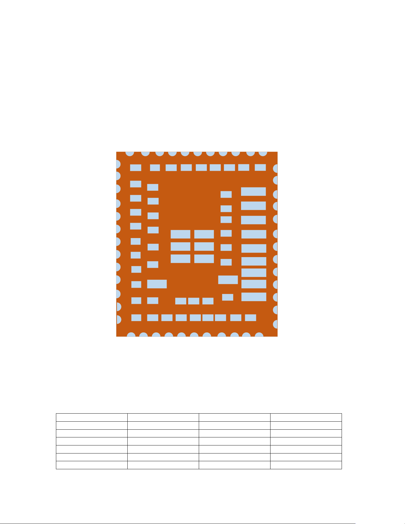
4. Pin Definition
4.1 Pin Layout
1
2
3
4
5
6
7
8
9
10
11
222120191817161514
97
36
37
38
39
40
41
42
43
44
33
32
31
30
29
28
27
26
25
24
23
GND
NC
NC
NC
NC
NC
PWRKEY
NC
ADC0
GND
USIM1_DATA
USIM1_VCC
RST_N
NET_STATUS
UART1_RXD
UART1_TXD
UART1_DTRN
UART1_RI
UART1_DCD
UART1_CTS
UART1_RT S
VDD_EXT
STATUS
NC
GND
UART2_TXD
NC
NC
NC
NC
GND
GND
UART0_RXD
UART0_TXD
GND
VBAT
VBAT
NC
12
USIM1_RST
13
USIM1_CLK
95
GND
96
ADC1
UART2_RXD
NC
35
34
GND
ANT
GND
98
NC
94
GND
90
GND
91
GND
92
GND
89
GND
93
GND
79
USIM1_DET
82
USB_BOOT
64
USIM2_DATA
63
USIM2_RST
62
USIM2_CLK
60
USB_DM
59
USB_DP
65
USIM2_VCC
61
USB_VBUS
99
NC
106
NC
72
GND
71
GND
70
GND
88
GND
69
NC
68
NC
105
NC
104
NC
45
GND
46
GND
47
GND
48
GND
49
NC
50
NC
51
NC
52
NC
53
NC
100
NC
73
GND
74
NC
75
NC
76
NC
77
NC
78
NC
80
NC
101
NC
54
NC
55
NC
56
NC
57
NC
58
NC
102
NC
103
NC
66
I2C0_SDA
67
I2C0_SCL
87
NC
86
NC
85
NC
84
NC
83
NC
81
NC
107
NC
108
NC
109
NC
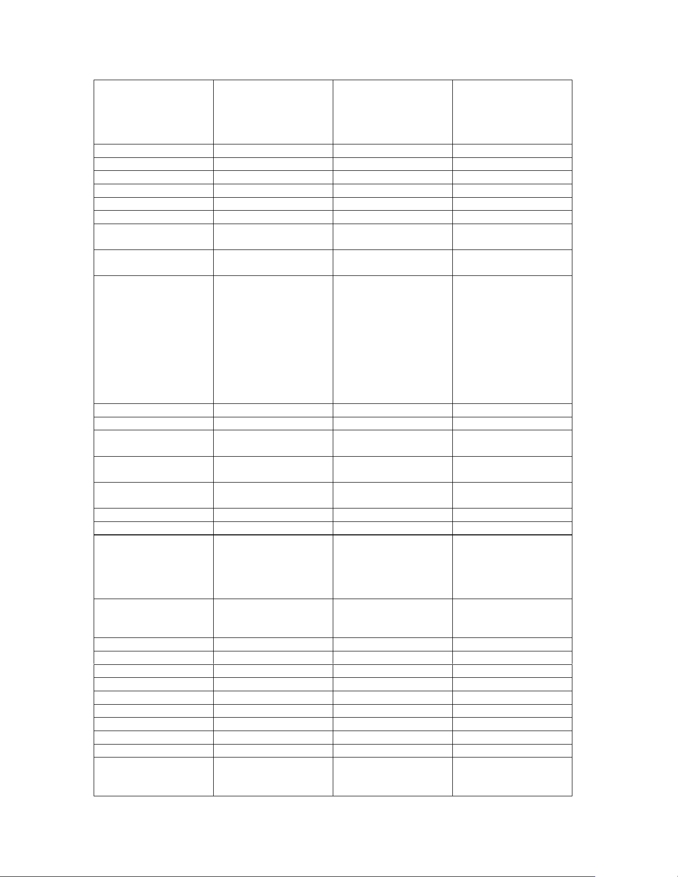
4.2 Pin Description
No.
Name
Type
Description
1
GND
GND
Ground
2
NC
-
Not connected
3
NC
-
Not connected
4
NC
-
Not connected
5
NC
-
Not connected
6
NC
-
Not connected
7
PWRKEY
DI
Module power on:
Pull low for >=500ms
or ground; Module
power off: Pull low
for >=650ms
8
NC
-
Not connected
9
ADC0
AI
0~1.2V, 12-bit
10
GND
GND
Ground
11
USIM1_DATA
DIO
USIM1 card data
12
USIM1_RST
DO
USIM1 card reset
13
USIM1_CLK
DO
USIM1 card clock
14
USIM1_VDD
PO
USIM1 card power
supply
15
RESET_N
DI
Module reset: Pull
low for >=300ms
16
NET_STATUS
DO
Network search: Slow
flash (200ms H /
1800ms L); Standby:
Slow flash (1800ms
H / 200ms L); Data
transfer: Fast flash
(125ms H / 125ms L);
Note: Connected to
USB_BOOT
internally
17
UART1_RXD
DI
Main UART receive
18
UART1_TXD
DO
Main UART transmit
19
UART1_DTR
DI
Main UART data
terminal ready
20
UART1_RI
DO
Main UART ring
indicator output
21
UART1_DCD
DO
Main UART carrier
detect output
22
UART1_CTS
DO
Clear to send
23
UART1_RTS
DI
Request to send
24
VDD_EXT
PO
Test point reserved.
Requires 1uF
capacitor + TVS. For
external pull-up only
(>=4.7kohm)
25
STATUS
DO
Module power on
indicator (high level
output)
26
NC
-
Not connected
27
GND
GND
Ground
28
UART2_RXD
DI
UART2 receive
29
UART2_TXD
DO
UART2 transmit
30
NC
-
Not connected
31
NC
-
Not connected
32
NC
-
Not connected
33
NC
-
Not connected
34
GND
GND
Ground
35
ANT_MAIN
ANT
Antenna port, 50ohm
characteristic
impedance

36
GND
GND
Ground
37
GND
GND
Ground
38
UART0_RXD
DI
DEBUG UART
receive
39
UART0_TXD
DO
DEBUG UART
transmit
40
GND
GND
Ground
41
GND
GND
Ground
42
VBAT
PI
External power, 1.2A
required. TVS
recommended. Test
point reserved.
43
VBAT
PI
External power, 1.2A
required. TVS
recommended. Test
point reserved.
44
NC
-
Not connected
45
GND
GND
Ground
46
GND
GND
Ground
47
GND
GND
Ground
48
GND
GND
Ground
59
USB_DP
AIO
USB positive, 90ohm
differential
impedance required
60
USB_DM
AIO
USB negative,
90ohm differential
impedance required
61
USB_VBUS
AI
3.0V~5.25V, test
point reserved
62
USIM2_CLK
DO
USIM2 card clock
63
USIM2_RST
DO
USIM2 card reset
64
USIM2_DATA
DIO
USIM2 card data
65
USIM2_VDD
PO
USIM2 card power
supply
66
I2C0_SDA
-
I2C0 data
67
I2C0_SCL
-
I2C0 clock
68
NC
-
Not connected
69
NC
-
Not connected
70
GND
GND
Ground
71
GND
GND
Ground
72
GND
GND
Ground
73
GND
GND
Ground
74
NC
-
Not connected
75
NC
-
Not connected
76
NC
-
Not connected
77
NC
-
Not connected
78
NC
-
Not connected
79
USIM1_DET
DI
USIM1 card hot-swap
detection
80
NC
-
Not connected
81
NC
-
Not connected
82
USB_BOOT
DI
Test point reserved.
Pull up to VDD_EXT
before power on for
forced download
mode.
83
NC
-
Not connected
84
NC
-
Not connected
85
NC
-
Not connected
86
NC
-
Not connected
87
NC
-
Not connected
88
GND
GND
Ground
89
GND
GND
Ground
90
GND
GND
Ground
91
GND
GND
Ground
92
GND
GND
Ground
93
GND
GND
Ground
94
GND
GND
Ground
95
GND
GND
Ground
96
ADC1
AI
0~1.2V, 12-bit
97
NC
-
Not connected
98
NC
-
Not connected
99
NC
-
Not connected
100
NC
-
Not connected
101
NC
-
Not connected
102
NC
-
Not connected
103
NC
-
Not connected
104
NC
-
Not connected
105
NC
-
Not connected
106
NC
-
Not connected
107
NC
-
Not connected
108
NC
-
Not connected
109
NC
-
Not connected
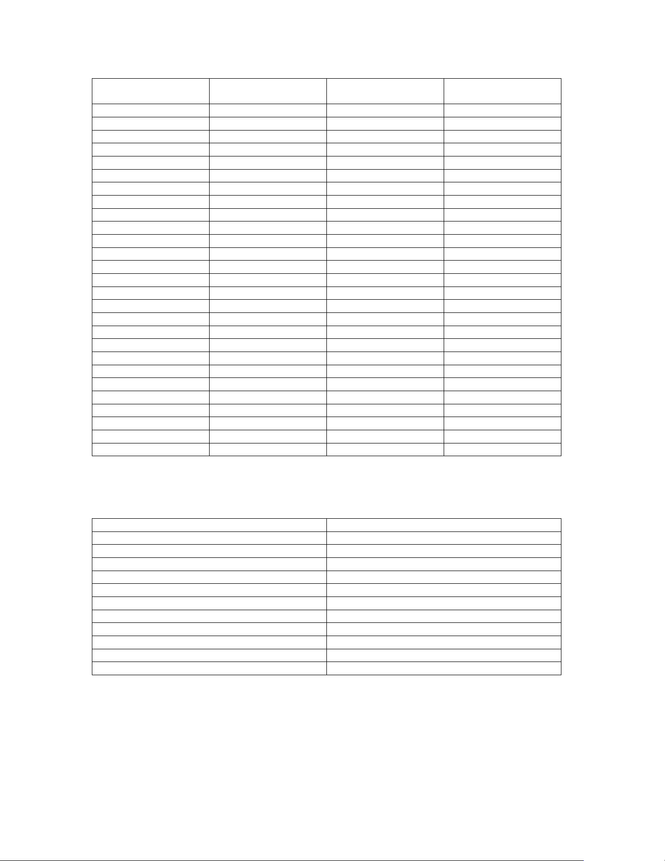
Pin Type Legend
Type
Description
GND
Ground
DI
Digital Input
DO
Digital Output
DIO
Digital Input/Output
AI
Analog Input
AO
Analog Output
AIO
Analog Input/Output
PI
Power Input
PO
Power Output
ANT
Antenna
NC
Not Connected

FCC Statement
This device complies with part 15 of the FCC Rules. Operation is subject to the following two
conditions:
(1) This device may not cause harmful interference, and
(2) this device must accept any interference received, including interference that may cause undesired
operation.
Any Changes or modifications not expressly approved by the party responsible for compliance could void
the user's authority to operate the equipment.
This equipment complies with FCC radiation exposure limits set forth for an uncontrolled environment.
This equipment should be installed and operated with minimum distance 20cm between the radiator &
your body.
Any company of the host which install this modular with Single modular approval should perform the test
of radiated emission and spurious emission according to FCC part 15C : 15.247 and 15.209 requirement,
Only if the test result comply with FCC part 15C : 15.247 and 15.209 requirement, then the host can be
sold legally.
FCC Radiation Exposure Statement
This modular complies with FCC RF radiation exposure limits set forth for an uncontrolled
environment. This transmitter must not be co-located or operating in conjunction with any other
antenna or transmitter. This modular must be installed and operated with a minimum distance of 20 cm between
the radiator and user body.
Note: This equipment has been tested and found to comply with the limits for a Class B digital
device, pursuant to part 15 of the FCC Rules. These limits are designed to provide reasonable
protection against harmful interference in a residential installation. This equipment generates
uses and can radiate radio frequency energy and, if not installed and used in accordance with the
instructions, may cause harmful interference to radio communications. However, there is no
guarantee that interference will not occur in a particular installation. If this equipment does
cause harmful interference to radio or television reception, which can be determined by turning
the equipment off and on, the user is encouraged to try to correct the interference by one or
more of the following measures:
-Reorient or relocate the receiving antenna.
-Increase the separation between the equipment and receiver.
-Connect the equipment into an outlet on a circuit different from that to which the receiver is
connected.
-Consult the dealer or an experienced radio/TV technician for help.

OEM INTEGRATION INSTRUCTIONS:
This device is intended only for OEM integrators under the following conditions:
The module must be installed in the host equipment such that 20 cm is maintained between the antenna
and users, and the transmitter module may not be co-located with any other transmitter or antenna. The
module shall be only used with the internal on-board antenna that has been originally tested and certified
with this module. External antennas are not supported. As long as these 3 conditions above are met,
further transmitter test will not be required.
However, the OEM integrator is still responsible for testing their end-product for any additional compliance
requirements required with this module installed (for example, digital device emissions, PC peripheral
requirements, etc.). The end-product may need Verification testing, Declaration of Conformity testing, a
Permissive Class II Change or new Certification. Please involve a FCC certification specialist in order to
determine what will be exactly applicable for the end-product.
Validity of using the module certification:
In the event that these conditions cannot be met (for example certain laptop configurations or co-location
with another transmitter), then the FCC/IC authorization for this module in combination with the host
equipment is no longer considered valid and the FCC ID/IC of the module cannot be used on the final
product. In these circumstances, the OEM integrator will be responsible for re-evaluating the end product
(including the transmitter) and obtaining a separate FCC authorization. In such cases, please involve a
FCC/IC certification specialist in order to determine if a Permissive Class II Change or new Certification is
required.
Upgrade Firmware:
The software provided for firmware upgrade will not be capable to affect any RF parameters as certified
for the FCC for this module, in order to prevent compliance issues.
End product labeling:
This transmitter module is authorized only for use in device where the antenna may be installed such that
20 cm may be maintained between the antenna and users. The final end product must be labeled in a
visible area with the following: “Contains Transmitter Module FCC ID: 2BS8J-SY288 Or Contains FCC ID:
2BS8J-SY288”
Information that must be placed in the end user manual:
The OEM integrator has to be aware not to provide information to the end user regarding how to install
or remove this RF module in the user's manual of the end product which integrates this module. The end
user manual shall include all required regulatory information/warning as show in this manual.

2.2 List of applicable FCC rules
List the FCC rules that are applicable to the modular transmitter. These are the rules that specifically
establish the bands of operation, the power, spurious emissions, and operating fundamental frequencies.
DO NOT list compliance to unintentional-radiator rules (Part 15 Subpart B) since that is not a condition of
a module grant that is extended to a host manufacturer. See also Section 2.10 below
concerning the need to notify host manufacturers that further testing is required.
Explanation: This module meets the requirements of FCC Part 2,22H,24E,27,90.
2.3 Summarize the specific operational use conditions
Describe use conditions that are applicable to the modular transmitter, including for example any limits
on antennas, etc. For example, if point-to-point antennas are used that require reduction in power or
compensation for cable loss, then this information must be in the instructions. If the use condition
limitations extend to professional users, then instructions must state that this information also extends
to the host manufacturer’s instruction manual. In addition, certain information may also be needed, such
as peak gain per frequency band and minimum gain, specifically for master devices in 5 GHz DFS bands.
Explanation: The EUT only FPC antenna.
2.4 Limited module procedures
If a modular transmitter is approved as a “limited module,” then the module manufacturer is responsible
for approving the host environment that the limited module is used with. The manufacturer of a limited
module must describe, both in the filing and in the installation instructions, the alternative means that
the limited module manufacturer uses to verify that the host meets the necessary requirements to
satisfy the module limiting conditions.
A limited module manufacturer has the flexibility to define its alternative method to address the
conditions that limit the initial approval, such as: shielding, minimum signaling amplitude, buffered
modulation/data inputs, or power supply regulation. The alternative method could include that the
limited module manufacturer reviews detailed test data or host designs prior to giving the host
manufacturer approval.
This limited module procedure is also applicable for RF exposure evaluation when it is necessary to
demonstrate compliance in a specific host. The module manufacturer must state how control of the
product into which the modular transmitter will be installed will be maintained such that full
compliance of the product is always ensured. For additional hosts other than the specific host
originally granted with a limited module, a Class II permissive change is required on the module grant
to register the additional host as a specific host also approved with the module.
Explanation: The Module is not a limited module.
2.5 Trace antenna designs
For a modular transmitter with trace antenna designs, see the guidance in Question 11 of KDB
Publication 996369 D02 FAQ – Modules for Micro-Strip Antennas and traces. The integration information
shall include for the TCB review the integration instructions for the following aspects: layout of trace
design, parts list (BOM), antenna, connectors, and isolation requirements.
a) Information that includes permitted variances (e.g., trace boundary limits, thickness, length,
width, shape(s),
dielectric constant, and impedance as applicable for each type of antenna);
b) Each design shall be considered a different type (e.g., antenna length in multiple(s) of frequency,

the wavelength, and antenna shape (traces in phase) can affect antenna gain and must be considered); c)
The parameters shall be provided in a manner permitting host manufacturers to design the printed
circuit (PC) board layout;
d) Appropriate parts by manufacturer and specifications;
e) Test procedures for design verification; and
f) Production test procedures for ensuring compliance.
The module grantee shall provide a notice that any deviation(s) from the defined parameters of the
antenna trace, as described by the instructions, require that the host product manufacturer must notify
the module grantee that they wish to change the antenna trace design. In this case, a Class II permissive
change application is required to be filed by the grantee, or the host manufacturer can take responsibility
through the change in FCC ID (new application) procedure followed by a Class II permissive change
application.
Explanation: Yes, The module with Snap fastener port designs, and this EUT has been shown the layout of
trace design, antenna, connectors requirements.
2.6 RF exposure considerations
It is essential for module grantees to clearly and explicitly state the RF exposure conditions that permit a
host product manufacturer to use the module. Two types of instructions are required for RF exposure
information: (1) to the host product manufacturer, to define the application conditions (mobile, portable
– 20cm from a person’s body); and (2) additional text needed for the host product manufacturer to
provide to end users in their end-product manuals. If RF exposure statements and use conditions are not
provided, then the host product manufacturer is required to take responsibility of the module through a
change in FCC ID/IC (new application).
Explanation: This module complies with FCC RF radiation exposure limits set forth for an uncontrolled
environment, This equipment should be installed and operated with a minimum distance of 20
centimeters between the radiator and your body." This module is designed to comply with the FCC
statement, “Contains Transmitter Module FCC ID: 2BS8J-SY288 Or Contains FCC ID: 2BS8J-SY288”.
2.7 Antennas
A list of antennas included in the application for certification must be provided in the instructions. For
modular transmitters approved as limited modules, all applicable professional installer instructions must
be included as part of the information to the host product manufacturer. The antenna list shall also
identify the antenna types (monopole, PIFA, dipole, etc. (note that for example an “omni-directional
antenna” is not considered to be a specific “antenna type”)).
For situations where the host product manufacturer is responsible for an external connector, for example
with an RF pin and antenna trace design, the integration instructions shall inform the installer that
unique antenna connector must be used on the Part 15 authorized transmitters used in the host product.
The module manufacturers shall provide a list of acceptable unique connectors.
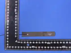
Explanation: The EUT has a FPC antenna, and the antenna use a antenna which is unique.
Model: itp024005-EX5G0-1
Type: FPC Antenna
Manufacturer: Hangzhou Vision Link Intelligence Technology Co., Ltd
Antenna gain:
LTE 2:0.35 dBi, LTE 4:1.71 dBi, LTE 5:1.4 dBi, LTE 7:0.75 dBi, LTE 12:2.17 dBi
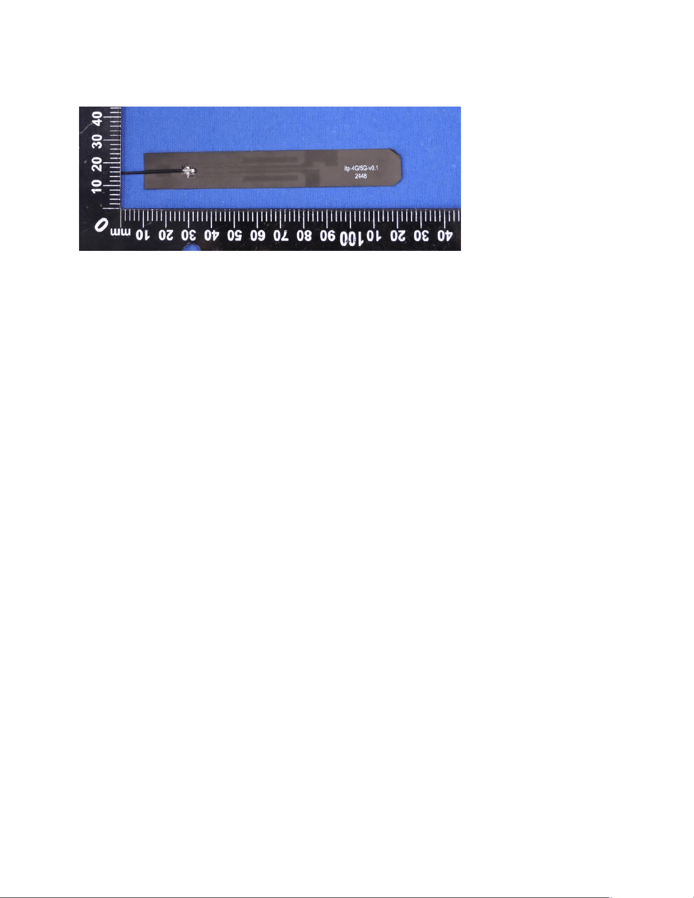
LTE 13:2.15 dBi, LTE 14:0.69 dBi, LTE 17:2.17 dBi, LTE 25:0.35 dBi
LTE 26:1.4 dBi, LTE 38:-0.12 dBi, LTE 41:0.75 dBi, LTE 66:1.71 dBi, LTE 71:1.77 dBi
2.8 Label and compliance information
Grantees are responsible for the continued compliance of their modules to the FCC/IC rules. This
includes advising host product manufacturers that they need to provide a physical or e-label stating
“Contains FCC ID” with their finished product. See Guidelines for Labeling and User Information for RF
Devices – KDB Publication 784748.
Explanation: The host system using this module, should have label in a visible area indicated the following
texts: “Contains Transmitter Module FCC ID: 2BS8J-SY288 Or Contains FCC ID: 2BS8J-SY288”.
2.9 Information on test modes and additional testing requirements5
Additional guidance for testing host products is given in KDB Publication 996369 D04 Module Integration
Guide. Test modes should take into consideration different operational conditions for a stand-alone
modular transmitter in a host, as well as for multiple simultaneously transmitting modules or other
transmitters in a host product.
The grantee should provide information on how to configure test modes for host product evaluation for
different operational conditions for a stand-alone modular transmitter in a host, versus with multiple,
simultaneously transmitting modules or other transmitters in a host.
Grantees can increase the utility of their modular transmitters by providing special means, modes, or
instructions that simulates or characterizes a connection by enabling a transmitter. This can greatly
simplify a host manufacturer’s determination that a module as installed in a host complies with FCC
requirements.
Explanation: Top band can increase the utility of our modular transmitters by providing instructions that
simulates or characterizes a connection by enabling a transmitter.
2.10 Additional testing, Part 15 Subpart B disclaimer
The grantee should include a statement that the modular transmitter is only FCC authorized for the
specific rule parts (i.e., FCC transmitter rules) listed on the grant, and that the host product manufacturer
is responsible for compliance to any other FCC rules that apply to the host not covered by the modular
transmitter grant of certification. If the grantee markets their product as being Part 15 Subpart B
compliant (when it also contains unintentional-radiator digital circuity), then the grantee shall provide a

notice stating that the final host product still requires Part 15 Subpart B compliance testing with the
modular transmitter installed.
Explanation: The module without unintentional-radiator digital circuity, so the module does not require
an evaluation by FCC Part 15 Subpart B. The host shoule be evaluated by the FCC Subpart B.