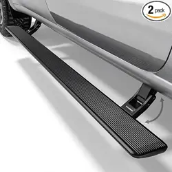

V01
POWER STEP
Installation Instructions
19+ Silverado 1500, 20+ Silverado 2500/3500 HD Double and Crew Cab
(Excl. 2019 LD Models)
19+ Sierra 1500, 20+ Sierra 2500/3500 HD Double and Crew Cab
(Excl. 2019 Limited Models)
RBPW061806 & RBPW061807
gears.wolox.com
The information in this manual is subject to change without notice.
1
INSTALLATION INSTRUCTIONS
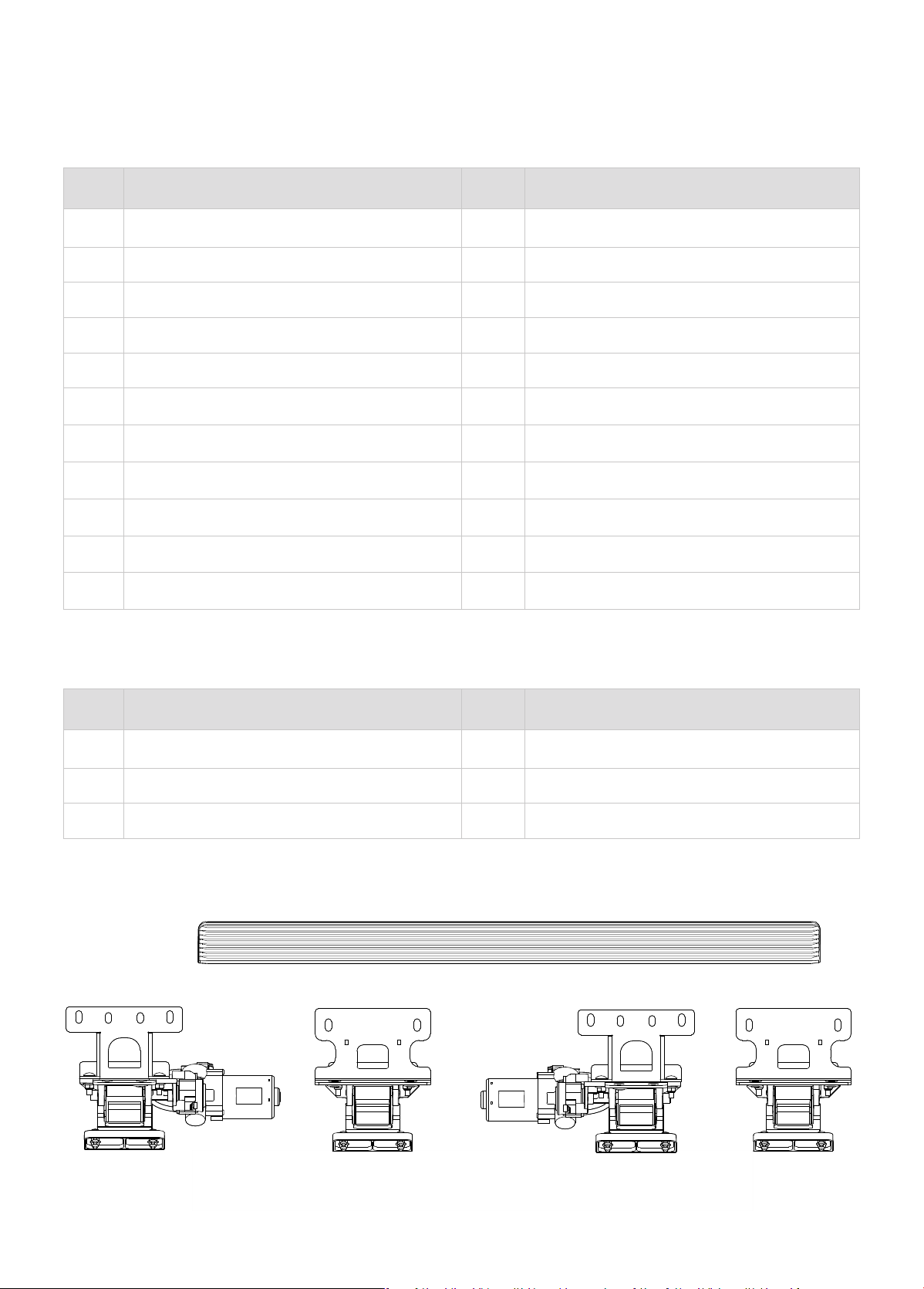
Qty Item Description Qty Item Description
2 Running Boards 12 8-1.25mm x 30mm Hex Bolts
1 Driver/Left Front Linkage Assembly 14 8mm Lock Washers
1 Passenger/Right Front Linkage Assembly 14 8mm x 24mm x 2mm Flat Washers
1 Driver/Left Rear Linkage Assembly 2 8mm Hex Nuts
1 Passenger/Right Rear Linkage Assembly 2 8-1.25mm x 40mm Bolt Plates
1 Electronic Materials Package 16 6mm Nylon Lock Nuts
2 Front Steel Mounting Brackets 16 6mm x 16mm x 1.6mm Flat Washers
2 Rear Steel Mounting Brackets
16
6-1.0mm x 20mm Carriage Bolts
16 8mm Flange Lock Nuts 2 Plastic Retainers
16 8-1.25mm x 30mm Carriage Bolts 15 Zip Ties
5 Double Sided Adhesive Tapes 1 Gloves
Qty Item Description Qty Item Description
1 Main Harness 1 ECU
2 Wire Taps 4 LED lights
1 LED Y-Harness (280mm) 1 LED Y-Harness (1200mm)
Electronic Materials Package Pas List
Packing List
Passenger Front Bracket
Assembly
Driver Rear
Bracket Assembly
Passenger Rear
Bracket Assembly
Driver Front Bracket
Assembly
A B DC
Running
Boards
2
Pas List
2
Tools Required:
NOTE
Driver and Passenger Rear
Bracket Assemblies are the
same.
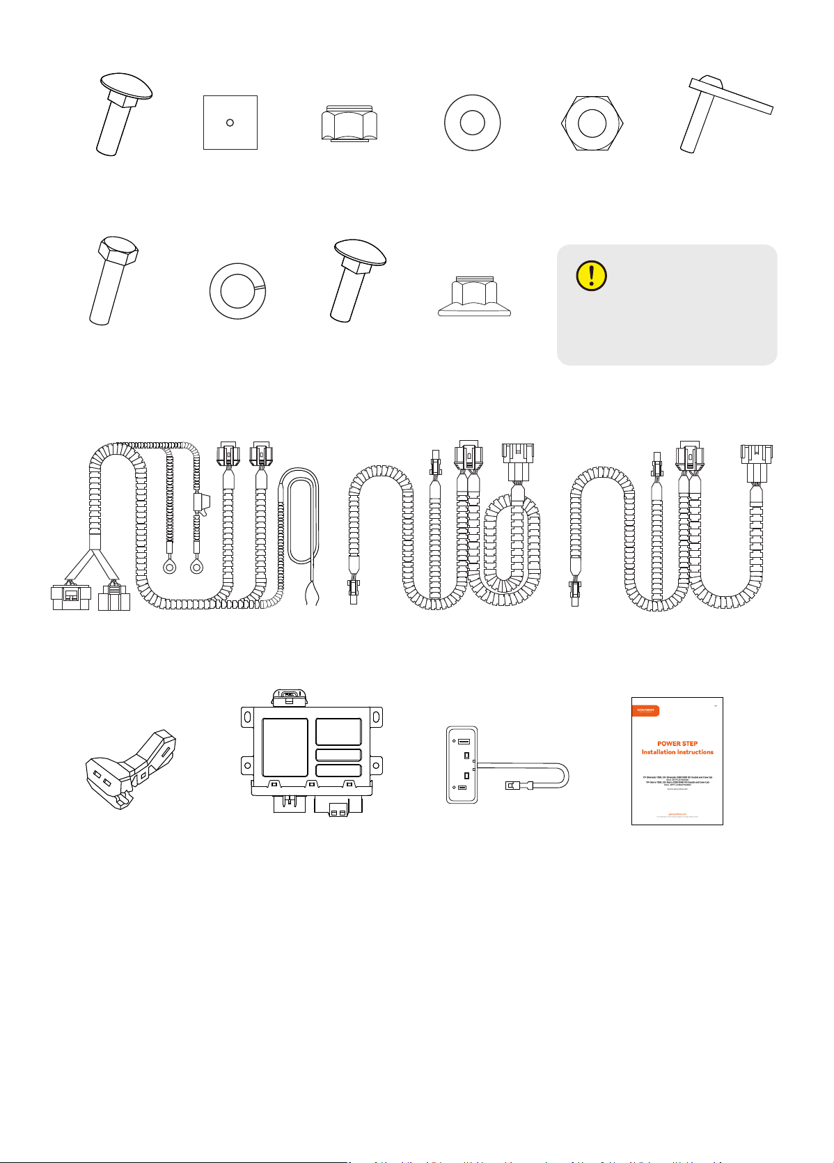
M6 Carriage
Bolt
M8 Hex Bolt
Main Harness
Wire Taps
Plastic
Retainer
Lock Washer
LED Y-Harness
(1200mm)
ECU
M6 Nylon
Lock Nut
M8 Carriage
Bolt
LED Y-Harness
(280mm)
LED Lights
User Manual
M8 Hex Nut M8 Bolt PlateFlat Washer
M8 Flanged
Lock Nut
E
K
M
O
F
L
N1
P
G
R
N2
Q Z
I JH
S
1. Rachet 2. Socket (8mm/10mm/13mm) 3. Extensions 4. Wrenches 5. Electrical Tape
6. Needle nose pliers
3
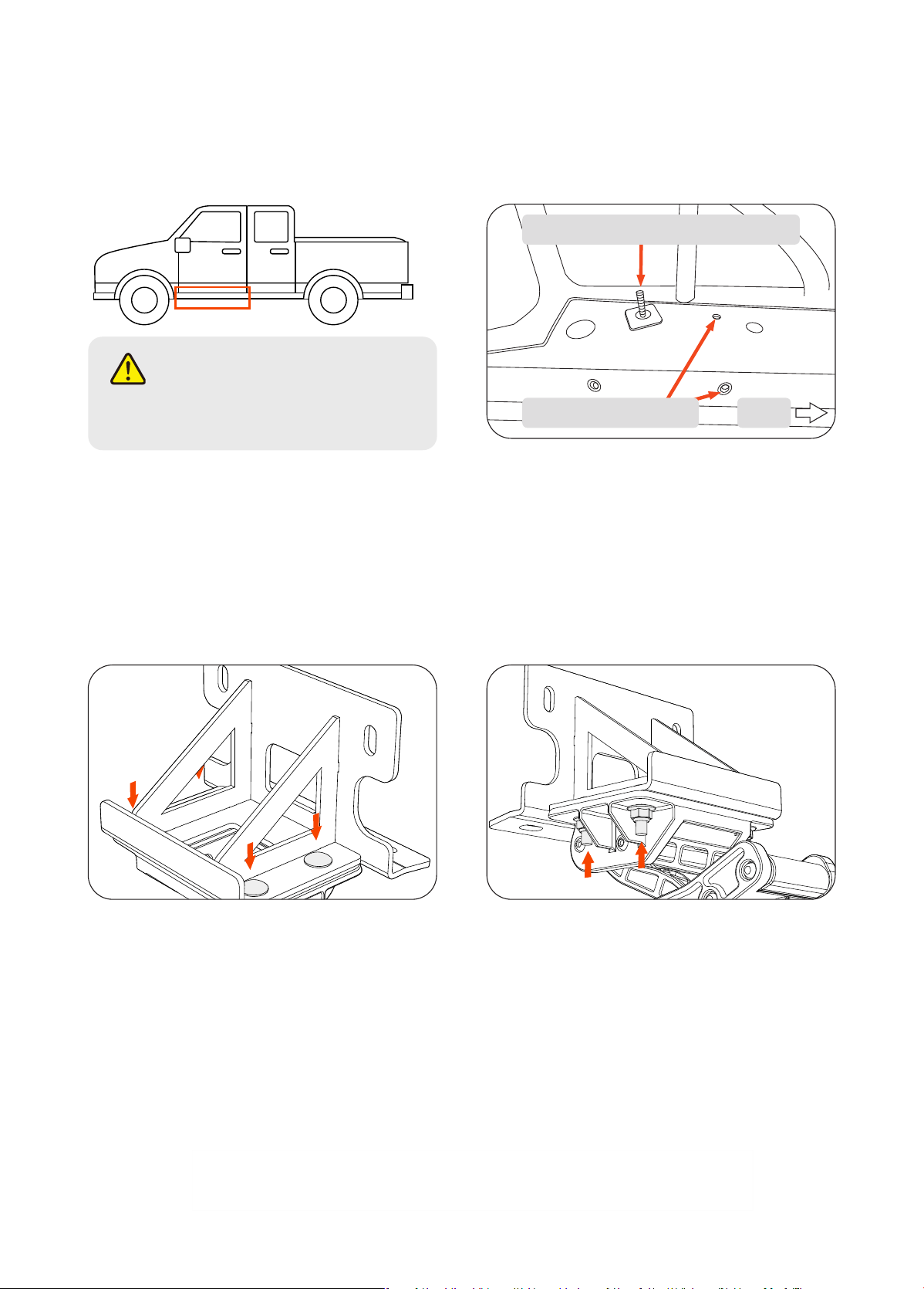
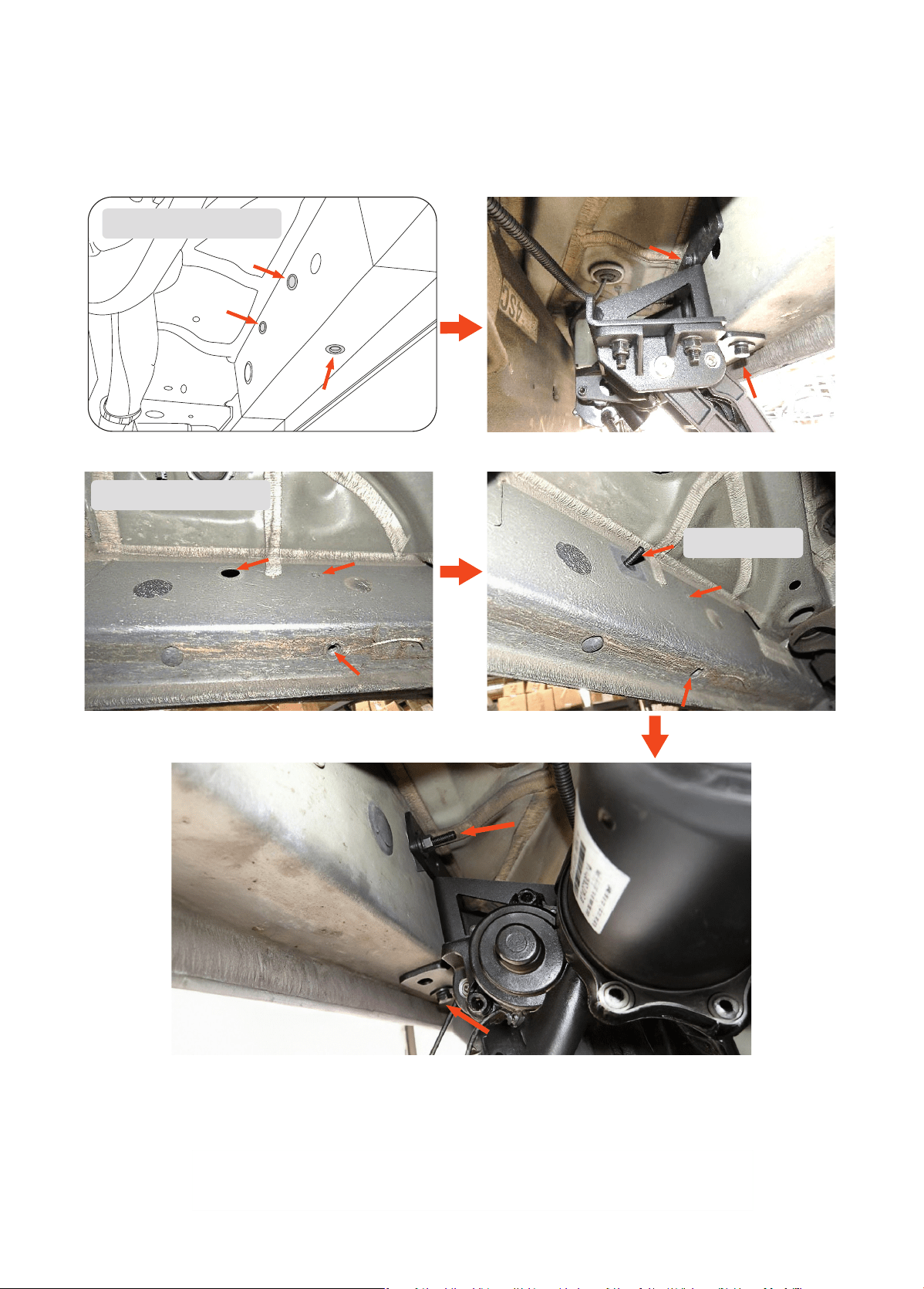
Locate Driver Side front mounting points on the rocker panel under the front door. Remove any OE plastic inse
caps on the mounting area. Inse the bolt plate (J) into the upper left hole with the bolt threads facing the frame.
Use the plastic retainer (F) to keep the bolt plate in place for mounting.
Take the mounting brackets and attach them to the linkage arms. First, inse the M8 Carriage Bolts into the
square slots on the brackets so that the threads are pointing downwards. Next, use the M8 Flanged Nylon Lock
Nuts to fasten the aluminum linkage arms to the brackets. There are 4 fastening points on each bracket.
・
Inse M8 Carriage Bolts downwards.
・
Tighten the M8 Flanged Nylon Lock Nuts all the way
until tight.
1
2
Bolt Plate held in place using retainer
OE rocker panel inses Front
NOTE
P-tool is recommended for removing
plastic inse caps.
4
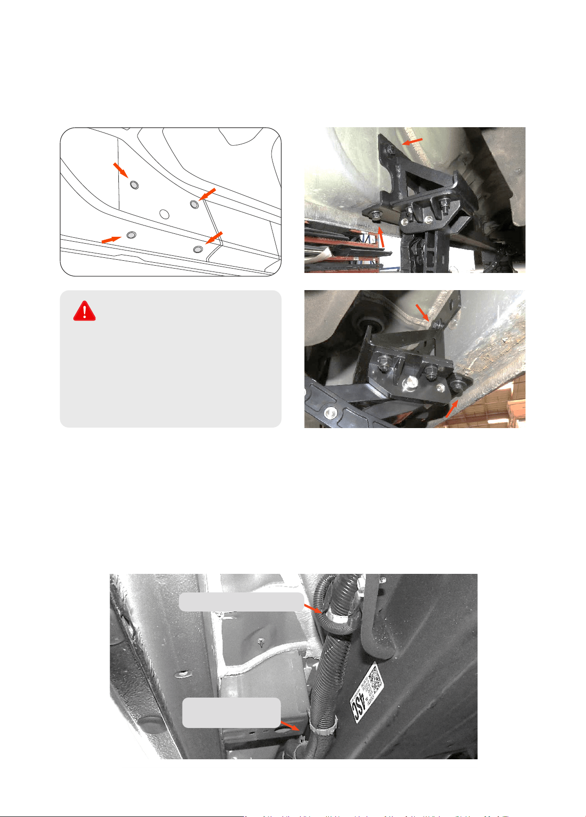
Locate and Line up front mounting bracket slots to the rocker panel threaded inses and place Driver Side/Left
Front Bracket Assembly (A) onto rocker panel. Then fasten 8mm Bolts, Lock Washers, and Flat Washers together
into the OE inses and 8mm Hex Nut to the Bolt Plate. Do not tighten all the way yet.
3
Perspective from front
Perspective from back
Nut goes here
5
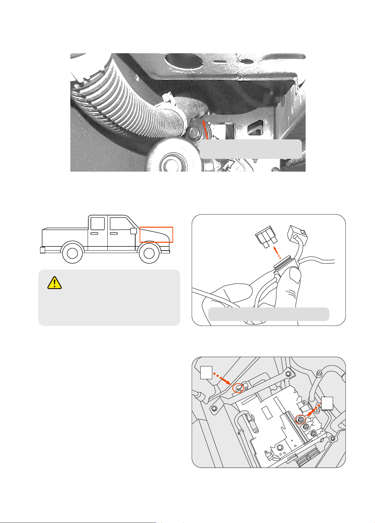
Locate rear mounting points. Remove the appropriate plastic OE inse protectors to reveal the threaded inses.
Next, line up rear mounting bracket slots to the studs and place Driver Side/Left Rear Bracket Assembly (B) onto
rocker panel. Remove any rubber plugs that may get in the way of the bracket.
Repeat steps 1 – 3 for the Passenger Side.
On some vehicles, the Passenger Side has large wire conduits running the length of the vehicle frame. These wire
harnesses are bendable and can be simply pushed aside when installing the Passenger Side Bracket Assemblies (C
& D).
Then fasten the 8mm bolts (K), lock washers (L), and at washers (H) into. Do not tighten all the way yet.
Adjustments may be needed afterwards.
4
5
NOTE
The more forward pair of inses are
additional mounting points. Not all vehicles
have these. On vehicles with these inses
available, be sure to use them for extra
additional strength. On vehicles without
these threaded inses, use just the
rearward 2 mounting points.
Passenger Side underside
OE Frame Conduit/
Harness
6
In some cases, foam strips may be applied to the top of the brackets in areas that will touch the OE frame
conduit. In most cases, the brackets will not touch.
May apply foam to where bracket
would touch the OE conduit.
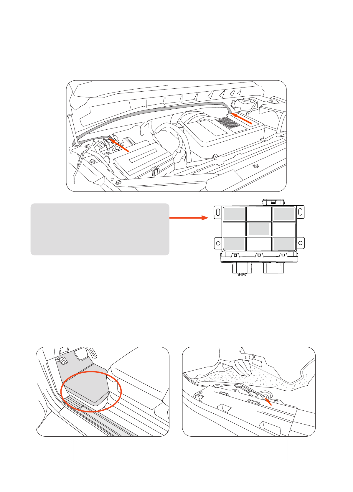
Sta from the engine compament by opening the front hood of the vehicle. Remove the 25A fuse from the fuse
box that comes with the main harness (M).
Connect the positive power lead on the main harness
(M) to the positive batte terminal. Connect the
negative lead to the negative batte terminal. Make
sure both power leads are fully secured. Connect the
ECU (P) to the main harness.
Connect the Long LED Y-Harness (N1) To the Driver-
side branch of the main harness.
Connect the Sho LED Y-Harness (N2)to the
Passenger-side branch of the main harness.
If the vehicle is either a 22+ Silverado 1500 or a 24+ Silverado 2500/3500, then route the CAN Signal wires to
the Passenger-Side instead of the Driver-Side, and go to Step 8B after Step 7.
6
7
WARNING
Keeping the fuse connected to the fuse box
may result in electrical sparks and risk of
shoing when working with the batte.
_
+
Open fuse holder cap and remove fuse
7
Route the main harness (M) around the batte, up along the rear of the engine compament, and down the
Driver-side wheel well. Route the shoer leg of the harness down the Passenger-side wheel well. Be sure to
avoid contact with any moving or hot engine components. Attach and secure the main harness (M) with
supplied cable ties.
Inside the vehicle cabin, remove the driver-side front kick panel and bottom door sill plate. Peel back the carpet
to access the hole where the grommet was removed. Feed the wires through.
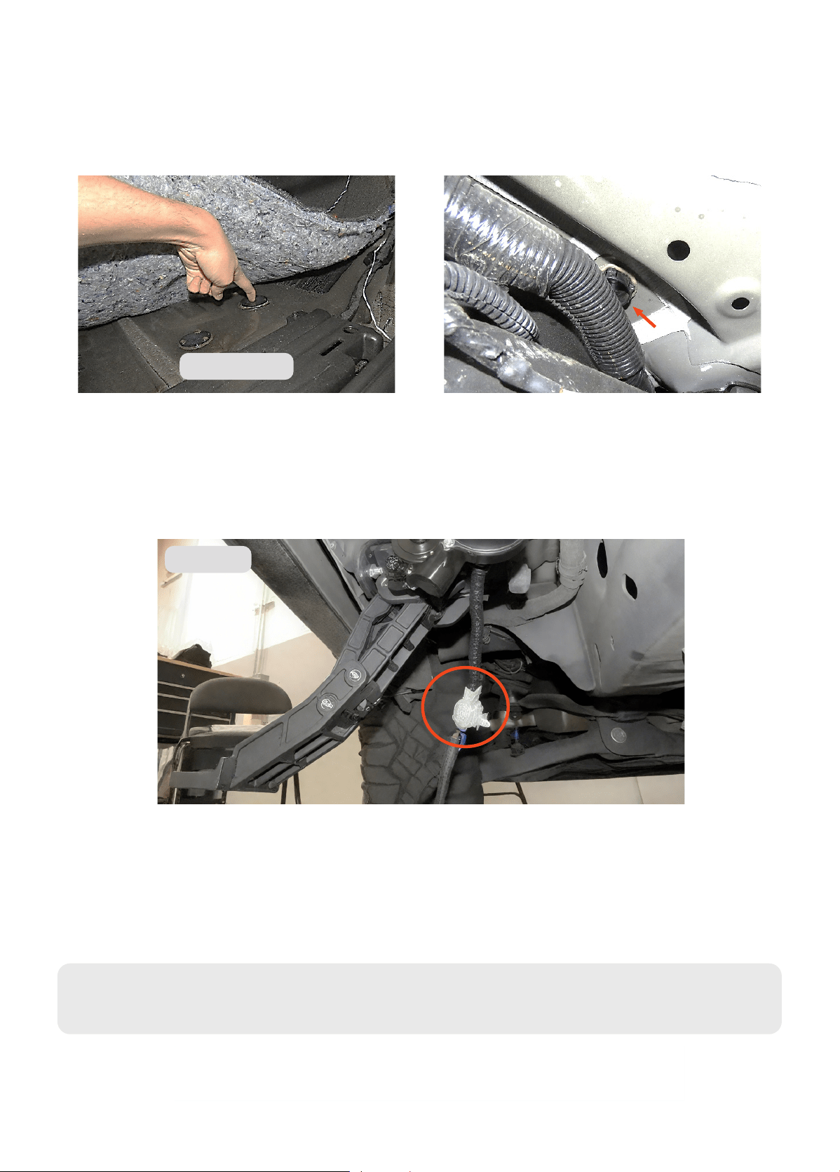
On the underside of the driver side, locate and remove the oor grommet in the oor panel behind the front
wheel well. The grommet will be close to the front linkage arm. Poke a hole through the grommet and thread the
two signal wires through and up into the vehicle cabin.
8
8A
・
Use the 5 included spare double-sided
adhesive tapes to secure the ECU, as needed.
・
ECU (M) should be secured near batte or
any space away from the direct heat of the
engine.
8
If the vehicle is a Silverado 1500 from 2022 onwards or a Silverado 2500/3500 from 2024 onwards, route the
signal branch of the main harness (M) through the Passenger side instead of the Driver Side. Poke a hole using a
drill or punch through the plastic cap on the underside to feed the wires into the cabin.
Attach the main harness (M) to the LED Y-Harness (N). Then attach the LED Y-Harness (N) to the motor on the
Driver Side. Repeat for Passenger Side. The shoer LED Y-Harness should connect to the motor that is on the
same side as the ECU.
8B
9
Driver side
Passenger side
Determine which technology system the vehicle is normally equipped with using the abridged guide below:
・
19-21 Silverado/Sierra 1500 & 20-23 Silverado/Sierra 2500-3500 HD = pre-refresh technology system
・
22+ Silverado/Sierra 1500 & 24+ Silverado/Sierra 2500-3500 HD = post-refresh technology system
・
22 Silverado 1500 LTD & 22 Sierra 1500 Limited = pre-refresh technology system
10
If the vehicle is equpiped with a pre-refresh tech system, follow Step 10-Pa A.
If the vehicle is equipped with a post-refresh tech system follow Step 10-Pa B instead (page 11).
9
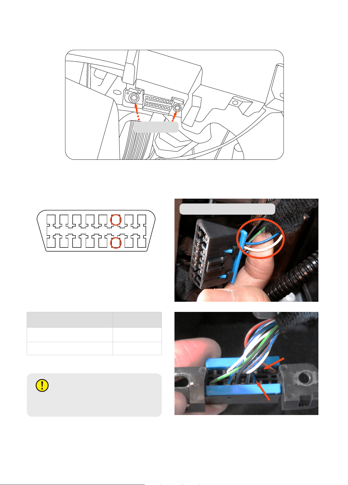
Pa A: Conrm the technology system of the vehicle. Locate the OBD-II Po under the steering wheel, near the
front hood release lever. Unbolt the two bolts using a socket for easier access to the rear side of the plug.
Connect the High and Low wires from the main harness (M) using the supplied wire taps (O). Identify wires from
back of the OBD-II Connector.
Find and use wire taps on corresponding
wires for Pin 6 and 14 on backside of OBD.
Pin 6 = CAN-H
Pin 14 = CAN-L
Unbolt OBD-II
Wire taps go to wires on backside
OBD-II Connector Pin Layout
1 2 3 4 5 6 7 8
9 10 11 12 13 14 15 16
Facto CAN Wire
Main Harness
wire color
3rd from right (lower), Pin 14
Yellow (Low)
3rd from right (upper), Pin 6 White (High)
After successfully connecting the wires, return the module back into its place, tighten the previously removed
nuts, and check that it is secure on the bracket.
NOTE
On some vehicles, wires may have dierent
colors than depicted here.
10
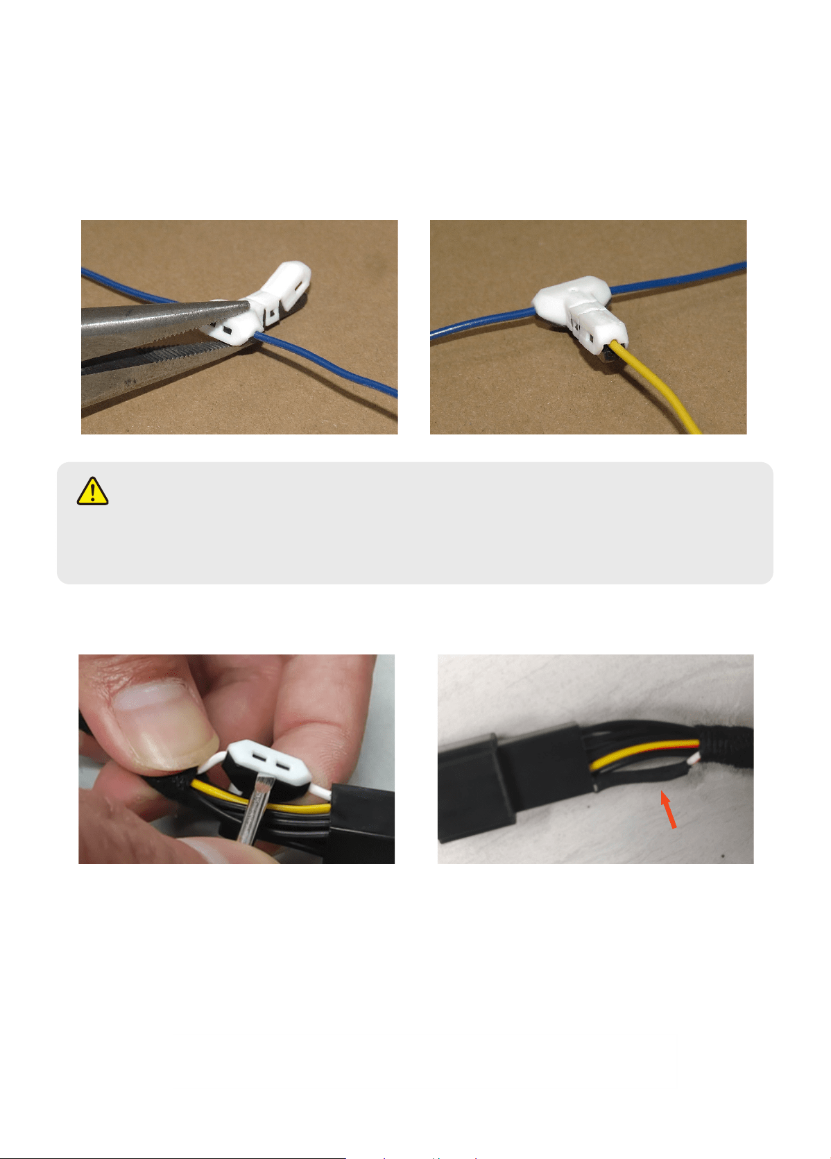
The kit comes supplied with wire taps called “shark taps”. Follow the guide below to tap the wire using the “shark
tap”:
・
Take wider end and wrap jaws onto vehicle data
line. Clamp jaws onto wire tightly.
・
Inse Power Step Main Harness signal wire into
narrow jaw. Clamp jaw onto wire tightly. Needle-
nose plyers recommended.
Wire Taps Guide
・
Use a screwdriver to p open the clamping buckle
of the wire tap.
・
Wrap the broken pa of the wire with electrical
tape. Re-do the tapping process.
NOTE
Make sure wire is seated properly in the jaws before clamping. The wire being tapped must be centered on
the “teeth” to make a proper tap. If the wire taps are not fully secured, please refer to below instructions
for details.
11
Pa B:
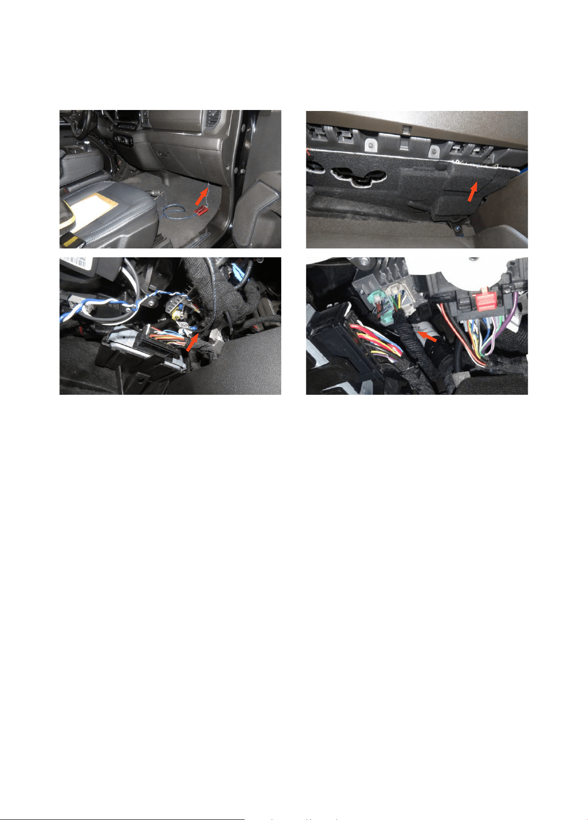
Conrm the technology system of the vehicle. Under the glove compament on the Passenger Side, locate the
radio module. On some models, the underside shield may have to be removed to access the components below
the glove compament.
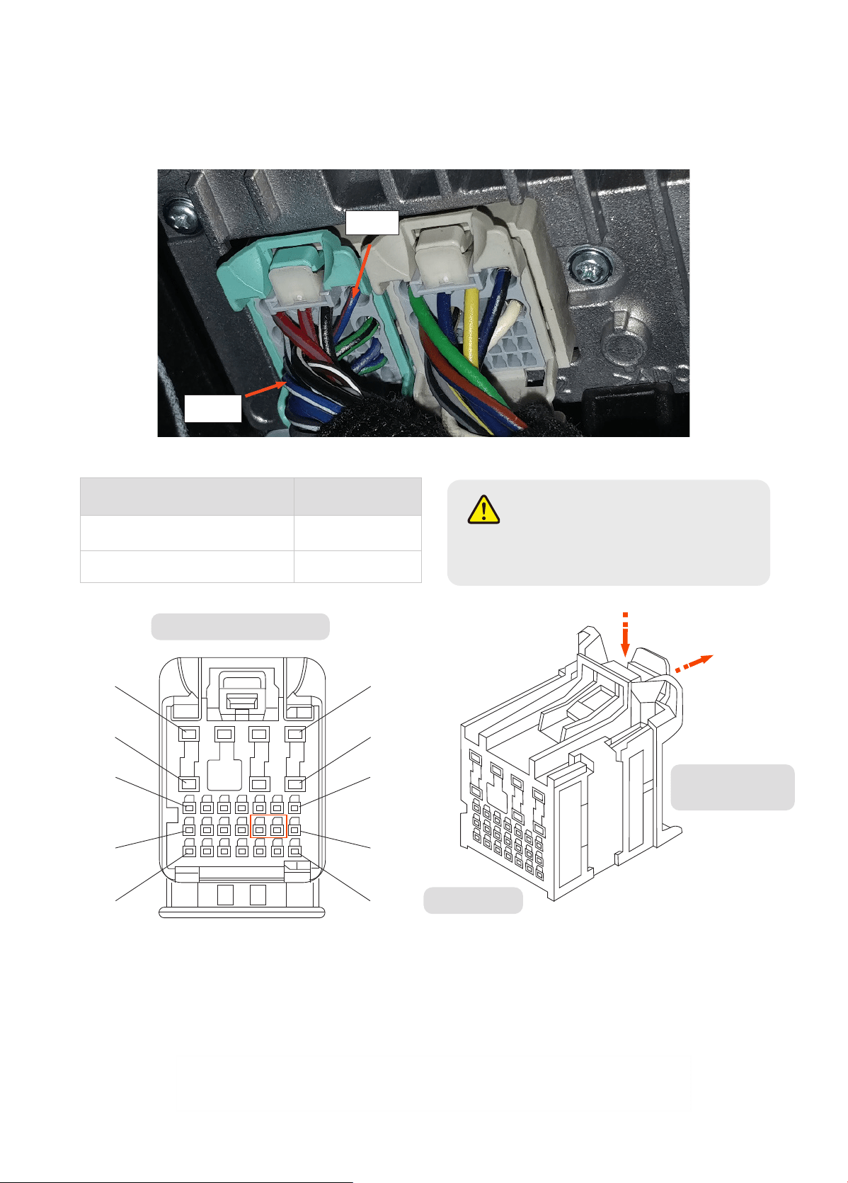
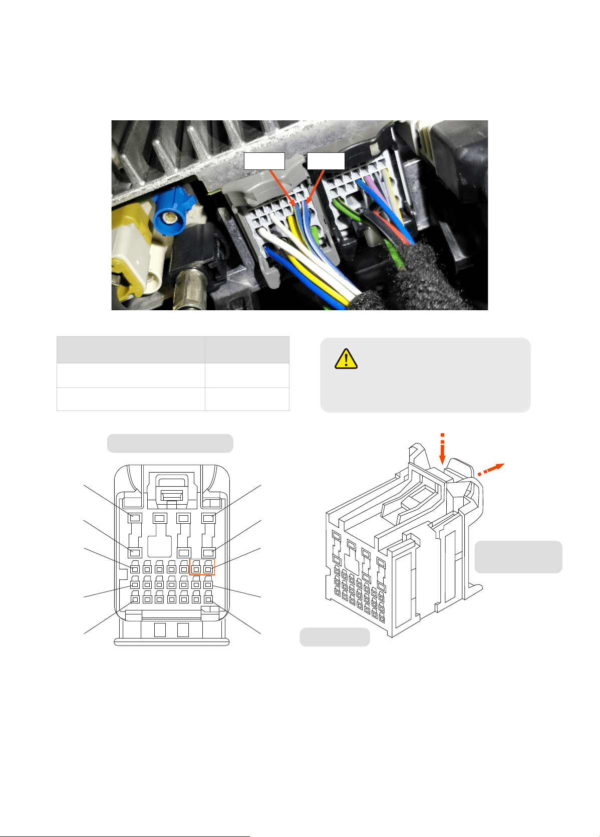
Determine the kind of radio that is installed by looking at the color of the two main connectors that are plugged
in.
If your radio has a GREEN and GREY plug, then follow step B-1.
If your radio has a BLACK and GREY plug, follow step B-2.
12
Facto CAN Wire
Main Harness
wire color
Blue w/ White Stripe (CAN-H) White (High)
Blue w/ Yellow Stripe (CAN-L) Yellow (Low)
After successfully connecting the wires, return the module back into its place, tighten the previously removed
nuts, and check that it is secure on the bracket.
Pin 17 = High
Pin 18 = Low
Pa B-1:
Connect the High and Low wires from the main harness (M) using the supplied wire taps (O). After successfully
connecting the wires, return the module back into its place, tighten the previously removed nuts, and check that
it is secure on the bracket.
NOTE
On some vehicles, the positions of the
Green and Grey plugs may be reversed.
Pin 16
Pin 4
4
8
15
22
29
1
5
9
16
23
2
1
4
8
15
22
29
1
5
9
16
23
2
1
Front of Plug
From perspective of Front
Backside of Plug
(where wires are)
13
Facto CAN Wire
Main Harness
wire color
Blue w/ White Stripe (CAN-H) White (High)
Blue w/ Yellow Stripe (CAN-L) Yellow (Low)
After successfully connecting the wires, return the module back into its place, tighten the previously removed
nuts, and check that it is secure on the bracket.
Pa B-2:
Connect the High and Low wires from the main harness (M) using the supplied wire taps (O). After successfully
connecting the wires, return the module back into its place, tighten the previously removed nuts, and check that
it is secure on the bracket.
NOTE
On some vehicles, the positions of the
Black and Grey plugs may be reversed.
Pin 9Pin 10
4
8
15
22
29
1
5
9
16
23
4
8
15
22
29
1
5
9
16
23
2
1
Front of Plug
From perspective of Front
Backside of Plug
(where wires are)
Pin 9 = High
Pin 10 = Low
14
Plug in LED lights (Q) into LED Y-Harness (N) and
attach them to the bottom of the rocker panel. Use
provided double sided adhesive tape on back of LED
light (Q).
・
LED attached to rocker panel.
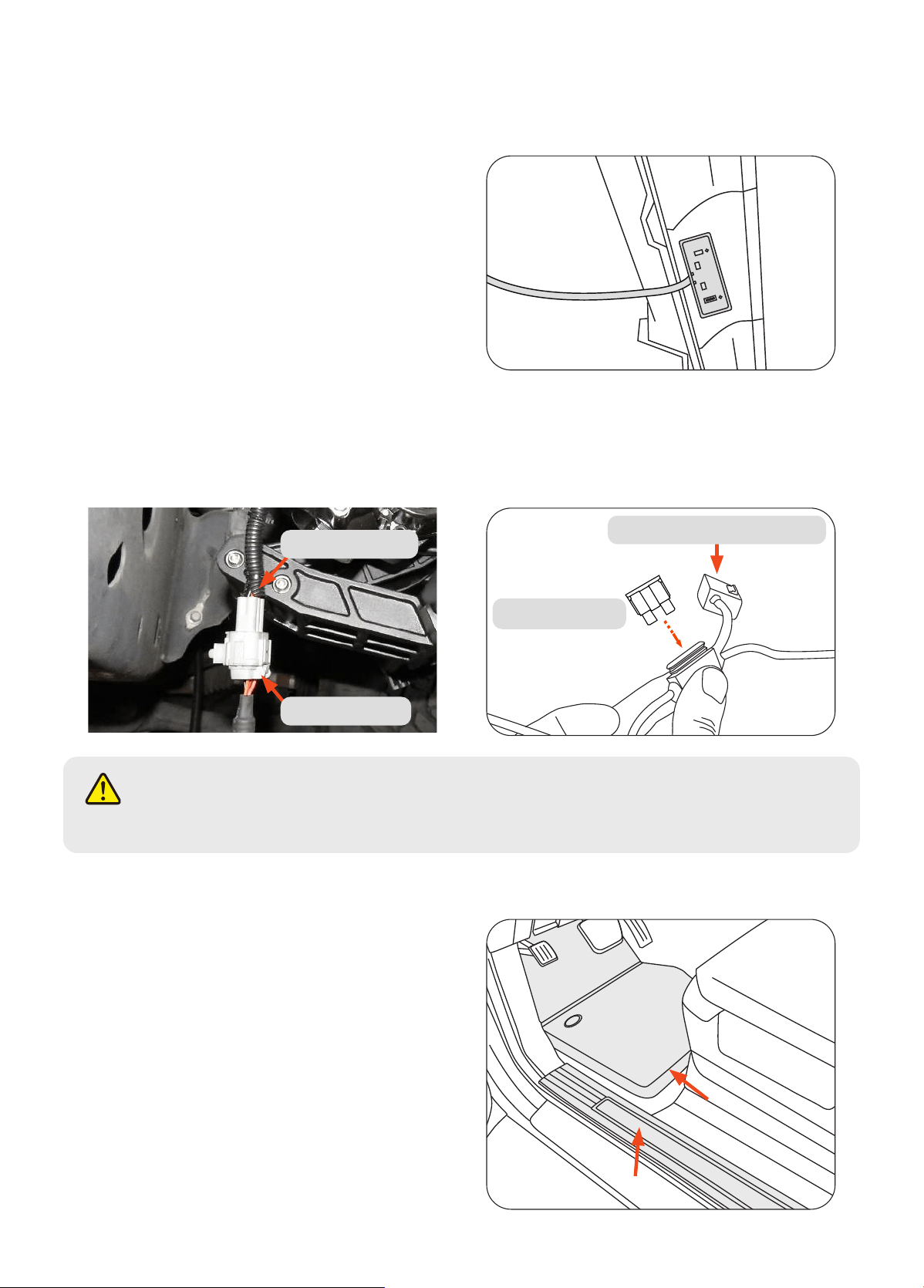
Check to make sure the harnesses on the Driver Side/Left Front Bracket Assembly (A) and Passenger Side Front
Bracket Assembly (C) are connected to the main harness (M) via the LED-Y harnesses (N).
Seal the grommet with RTV Silicone Sealant.
Hide wires and reattach the kick panel with the
carpet fully unfurled in its original position. Reattach
the door sill panel and check to make sure there are
no obstructions or potential snag points around the
brake pedal area.
11
12
13
NOTE
The linkage arms on the front bracket assemblies will not move unless both motors are connected.
Replace fuse into fuse box. Inse 25A fuse, close lid after replacing fuse.
Inse 25A Fuse
Close lid after replacing Fuse
Motor Connector
LED-Y Harness
15
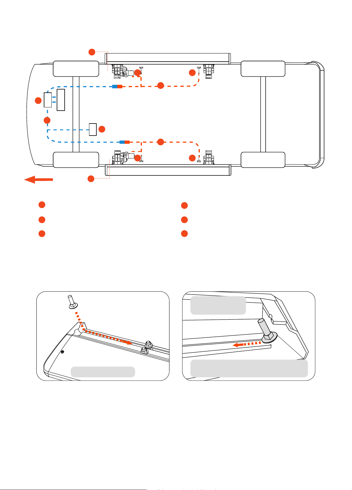
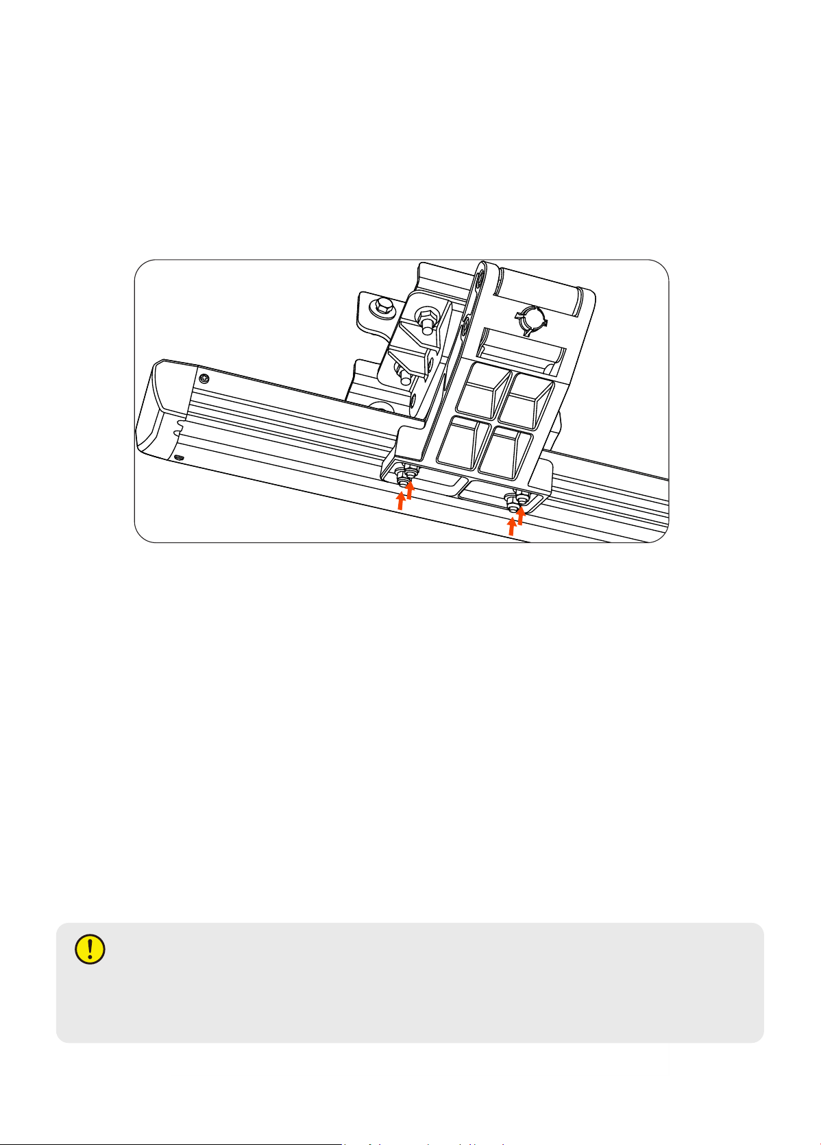
Prepare the power step boards. Locate the end of the boards and slide the M6 Carriage Bolts (E) into the channel
on the underside of the board. Inse a total of 8 carriage bolts (E). Use the notch in the board’s end caps to feed
the bolts into the channel.
14
BATTERY
ECU
CAN
Driver
1
1
3
4
5
5
2
6
6
6
6
Wiring Diagram
1
2
3
Motor
Main Harness (The Blue Line)
ECU
5
6
4
LED-Y-Harness (The Orange Line)
LED Lights*4
Facto CAN Wire/ Data Line
Section view of
underside channel
Carriage Bolt Channel
Use the notch in the board’s end caps to
feed the bolts into the channel.
16
Peorm a function check by closing the driver side front door and opening it again. The front bracket assembly (A)
motor should activate the linkage arm and move it into the down or “deployed” position.
After deploying linkage arms, unplug the motor connector from the LED-Y harness (to cut power to the linkage
arms), while front door is open, to hold deployed position for running board installation.
Line up the carriage bolts (E), under the power step boards, with the slots on the linkage arms (A & B). Inse the
8 carriage bolts (E) into the slots on front and rear linkage arms. Adjust board to desired position. Moderately
hand tighten the 6mm Flat Washers + 6mm Nylon Lock Nuts (G) onto the carriage bolts.
Once the board is adjusted, plug in motor connector to the LED-Y harness (to return power to the linkage arms),
making sure that the door remains open. Proceed to open and close doors several times to deploy and retract the
steps to settle the steps into their natural alignment. After cycling the step, tighten all hardware on the board and
brackets.
Some fuher adjustment may be required for desired step position. Repeat for passenger side.
15
Peorm system check and troubleshooting. If board is making irregular movements or noise, readjust the boards
as follows:
a. With board deployed loosen 6mm nuts under board.
b. Leave the nuts slightly less than snug.
c. Open and close door several times for board to settle into position.
d. With the step in the deployed position, gradually tighten the nuts while alternating between each. Do not over
tighten.
If board is making abnormal noise or the motion is binding, repeat steps “a” through “d”.
NOTE
If the above method does not resolve the issue, the brackets mounting to the vehicle may not be aligned
properly with the vehicle. In this case, remove the board and realign brackets before attempting steps “a”
to “d” once again.
16
17
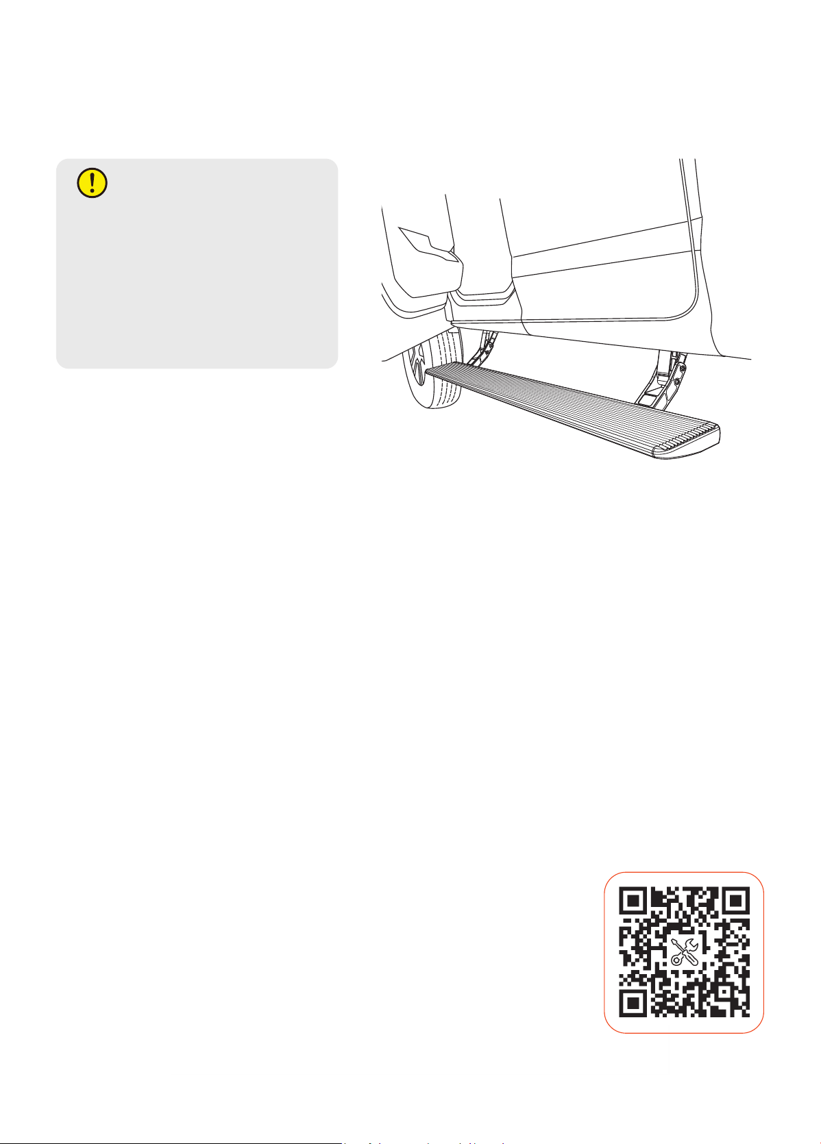
Reinstall any remaining trim panels if necessa. Check and make sure all hardware is fully tightened. Peorm a
nal system check. Finish.
NOTE
・
If board does not move during
troubleshooting, check the wire taps
for a solid connection or ip the
CAN Signal High and Low wires.
・
If board still does not move during
troubleshooting, it may also be
necessa to check all other wiring
connections.
17
Installation Video

18
・
Ensure there are no debris or obstacles preventing the power steps from operating.
・
Open and close each door on both sides to ensure that power steps are operating correctly.
・
Check and ensure that all electrical connections are stable and secure.
・
Check and ensure that the fuse is placed into the main harness.
・
Check and ensure that the CAN tap connections are fully engaged and are seated completely.
・
Recheck that all mounting hardware is tight.
・
Adjust mounting brackets or running board to enable smooth operation even after having stepped on the
deployed boards.
・
Periodically clean the linkage arms and motor of any di or debris that may accumulate.
・
Avoid spraying the motors directly with high pressure liquids.
・
Avoid damaging the power steps.
・
Ensure power step ECU is not exposed directly to water to prevent degradation.
・
Ensure wiring is properly tucked away and concealed from mechanically moving pas and exposure to high
heat or ve low temperature conditions.
・
Periodically recheck that all mounting hardware is tight.
・
Do not overload the running board.
・
Readjust running board if necessa.
・
Do not use boards as a rock slider or as skid protection.
・
Do not use solvents, chemicals, oils, or corrosive liquids on power steps. If the power steps encounter these
substances, clean the power steps as soon as possible. Mild detergent and water is recommended.
・
Do not obstruct the power steps in any way during operations of deployment and retraction.
・
Do not rely in any way on the components of this product to keep occupants within the vehicle or to protect
against inju or death in the event of an accident.
・
Do not sit/stand on the running board for long periods of time.
・
Do not jump on power step board or rest heavy objects on boards or subject power steps to excessive force.
・
Do not step on plastic end caps of the boards. Failure to do so may result in inju.
・
Do not place bodily appendages between running board and the vehicle body. Please mind the gap between
the vehicle and the board.
・
Do not allow children to use power steps without adult supeision and proper operation. This is not a toy.
Improper use may result in inju.
・
Remove the fuse on the power lead on the main harness before doing electrical troubleshooting to avoid risk
of shock or inju. Make sure the motors do not have power before working on mechanical adjustments to
avoid inju.
FINAL REMARKS
MAINTENANCE AND CARE
WARNING AND SAFETY
E-mail: seice@wolox.com
Phone: +1 888 296 8399
Check us out here!
We have professional customer seice!
Help Center WhatsApp