

- 1
XMAI | XM-8600A Industrial Controller User Manual
-
Copyright and Notice
Copyright © 2025 Wuhan Xiaomai Retail Technology Co., Ltd. All rights reserved.
No part of this document may be excerpted, copied, reproduced, or distributed in any form without prior written
authorization from Wuhan Xiaomai Retail Technology Co., Ltd.(“XMAI”).
The products, services, or features you purchased are subject to the applicable commercial agreement and terms. Some
products, services, or features described in this document may not be included in your specific purchase or configuration.
Unless otherwise stated in the applicable agreement, this document is provided for guidance only. All statements,
information, and recommendations in this document do not constitute an express or implied warranty.
Because products and software are updated periodically, the content of this manual may be revised without prior notice.

- 2
XMAI | XM-8600A Industrial Controller User Manual
-
Table of Contents
PART1
1. Safety Instructions..................................................................................................03
PART2
2. Product Description..................................................................................................03
PART3
3. Product Features.....................................................................................................03
PART4
4.Physical Dimensions
................................................................................................04
PART5
5.Specifications............................................................................................04
PART6
6.1 Interface Description.............................................................................................06
6.2 Side B Interface Layout........................................................................................06
6.3 Side C Interface Layout..................................................................................07
PART7
7. After-Sales Service...............................................................................................08

- 3
XMAI | XM-8600A Industrial Controller User Manual
-
PART1
1. Safety Information
1. This product is a precision electronic device. Avoid impact, drops, and strong vibration. Mechanical shock may loosen
components or damage internal circuits, which can cause functional issues.
2. During packaging and transportation, protect the product with bubble wrap, EPE foam, or equivalent cushioning
material.
3. Do not operate the product in ambient temperatures of 158°F (70°C) or higher, or -4°F (-20°C) or lower. Extreme
temperatures may reduce performance or cause abnormal operation.
4. Do not leave the controller exposed outside the equipment enclosure. Exposed installation can create a risk of electric
shock or accidental contact. The controller and the customer equipment must be properly grounded.
5. For best user experience, install the product in a low-interference environment with wireless signal strength stronger
than -90 dBm.
PART2
2. Product Overview
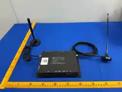
The XM-8600-A is an Android-based industrial controller designed for smart retail and vending applications. It uses a high-
performance quad-core ARM A53 processor and integrates a 4G cellular data module on the main board. The controller
provides multiple peripheral interfaces, including dual RJ45 Ethernet ports, four IP camera ports, USB, two electronic lock
interfaces, and one 12 V power output.
PART3
Product Features
● High-performance quad-core ARM A53 processor
● Android 10 operating system
● Integrated 4G wireless communication module
● Integrated PowerVR GE8300 GPU
● Rich peripheral interface support
● Low-power, fanless design
● Remote system upgrade support
- 4
XMAI | XM-8600A Industrial Controller User Manual
-
PART4
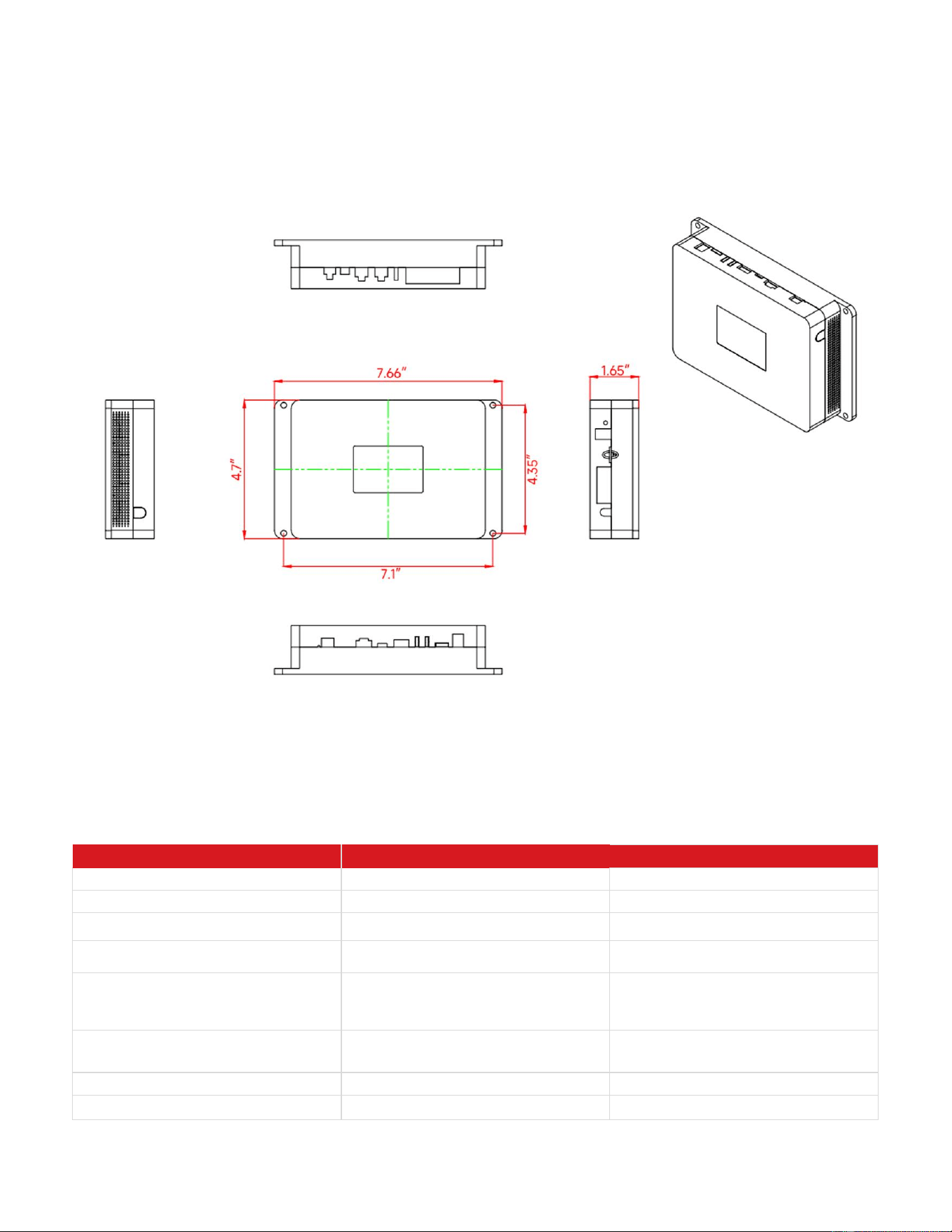
4. Physical Dimensions
Unit : inch
PART5
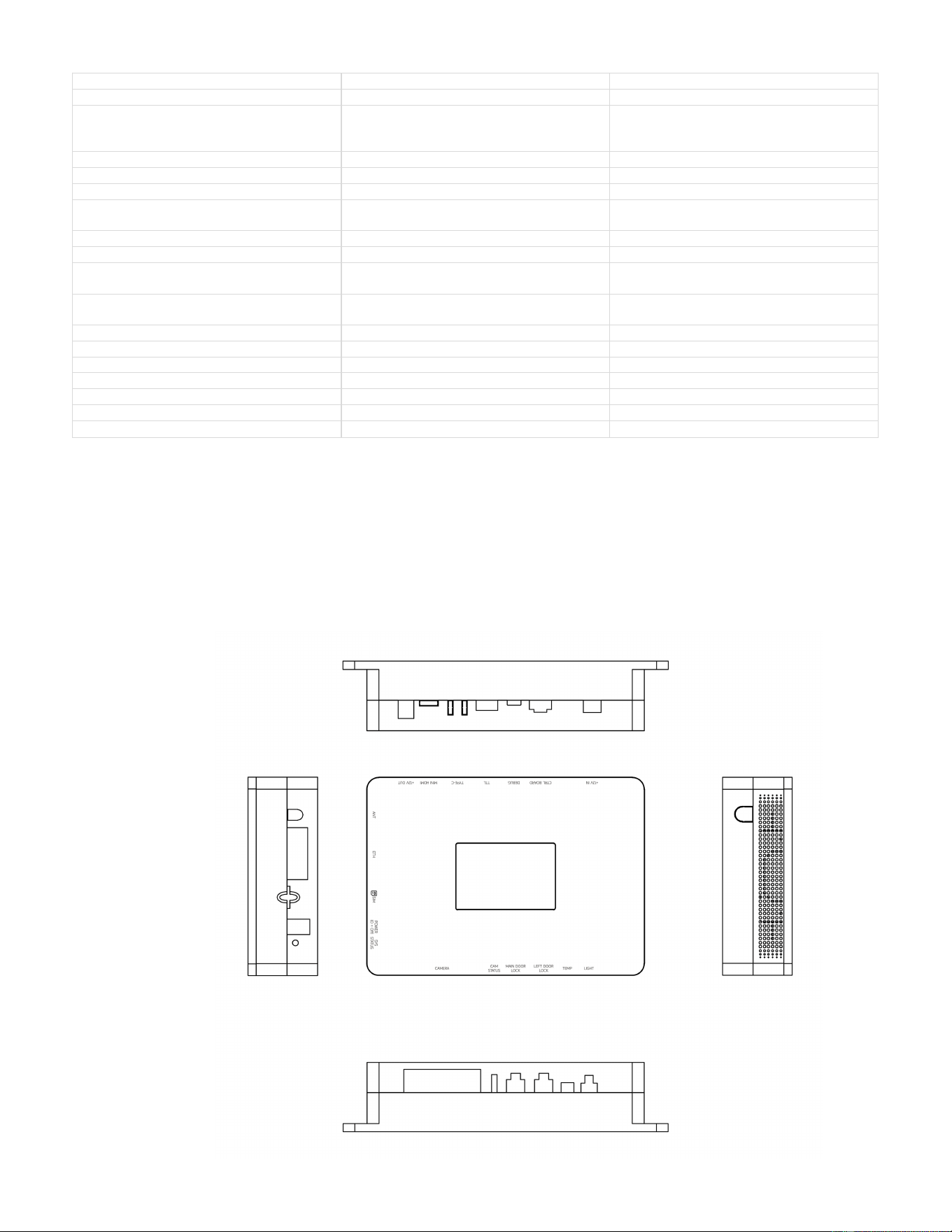
5. Specifications
Category Item Specification
System CPU
Quad-core ARM A53, 4 × 1.5 GHz
System GPU
Imagination PowerVR GE8300
System
Memory / Storage 1 GB RAM + 8 GB flash storage
System Operating System
Android 10
Network Cellular
4G cellular module. Carrier and band
compatibility must be confirmed for the
target U.S. carrier/SIM configuration.
Network Ethernet
RJ45, 100 Mbps
Interfaces Power Input DC 12 V / 3 A
Interfaces
SIM Card
eSIM + Micro SIM slot; dual-card, single-
- 5
XMAI | XM-8600A Industrial Controller User Manual
-
standby configuration
Interfaces
RS232
1 channel
Interfaces RS485
2 customizable RS485 channels, or
expandable to 2 RS232 channels;
hardware reserved
Interfaces
WLAN
2 channels
Interfaces
USB
1 channel
Interfaces
LOCK
2 channels
Interfaces LED Strip
1 channel; maximum single-channel output
12 V / 2 A
Interfaces
Speaker
Built-in 4 Ω, 3 W speaker
Interfaces
Keys
K2 reset, K3 flashing/programming
Indicators
Indicator Lights
6 channels: PWR, SYS, and 4 camera
indicators
RF 4G Antenna
SMA male external thread / female center
contact
Watchdog Hardware WDG
Hardware watchdog supported
Other Startup
Automatic startup after power-on
Other UPS Battery
Battery capacity greater than 1,500 mAh
Environment Operating Temperature
14°F to 140°F
Environment Storage Temperature -31°F to 176°F
Compliance Reference Electrostatic Discharge
Reference standard: GB/T 17626.2
Compliance Reference Electromagnetic Compatibility
Reference standard: GB/T 17626.3
This document is for reference only. Actual product configuration and appearance are subject to the delivered unit.
PART6
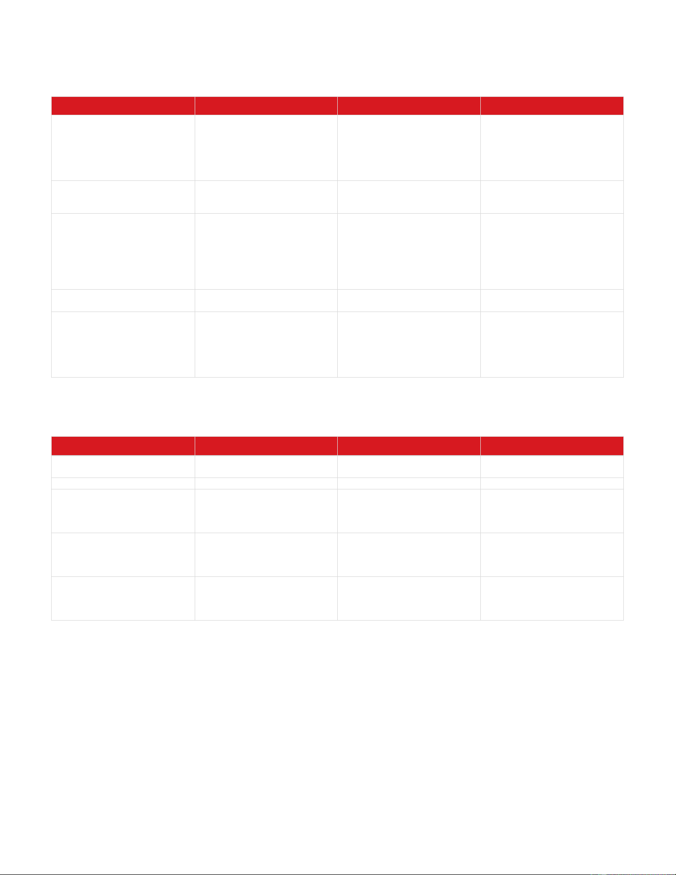
Interface Description
Connector orientation in the original diagrams is described from left to right.
- 6
XMAI | XM-8600A Industrial Controller User Manual
-
6.1 Side A Interfaces
Silkscreen / Label Name Description Notes
Camera Port Camera interface
Four RJ11 POP camera ports.
Cameras may be plugged into
any of the four ports. 6-pin
signal definition from left to
right: 12 V, GND, TX+, TX-,
RX+, RX-.
No fixed insertion order
required.
Camera LED Camera LED indicator
Fast flashing = normal. Slow
flashing = abnormal. Off = not
connected or not conducting.
LOCK1 / LOCK2
Electromagnetic lock interface
LOCK1: main lock for single-
door configuration. LOCK2: left
lock for dual-door
configuration. Pin definition: 1
lock feedback, 2 door
feedback, 3 common (COM), 4
lock control, 5 GND, 6 12 V.
2 × 3-pin connector, 0.12 in
pitch.
Temperature Sensor
Cabinet temperature sensor
2-pin non-polarized connection.
Connector model: XH-2AW.
Approx. 0.30 in × 0.28 in.
LED Strip
LED strip interface
Controlled independently by
the MCU. The LED output
remains available during
device restart. 2 LED strip
ports; maximum output per
port: 12 V / 1 A.
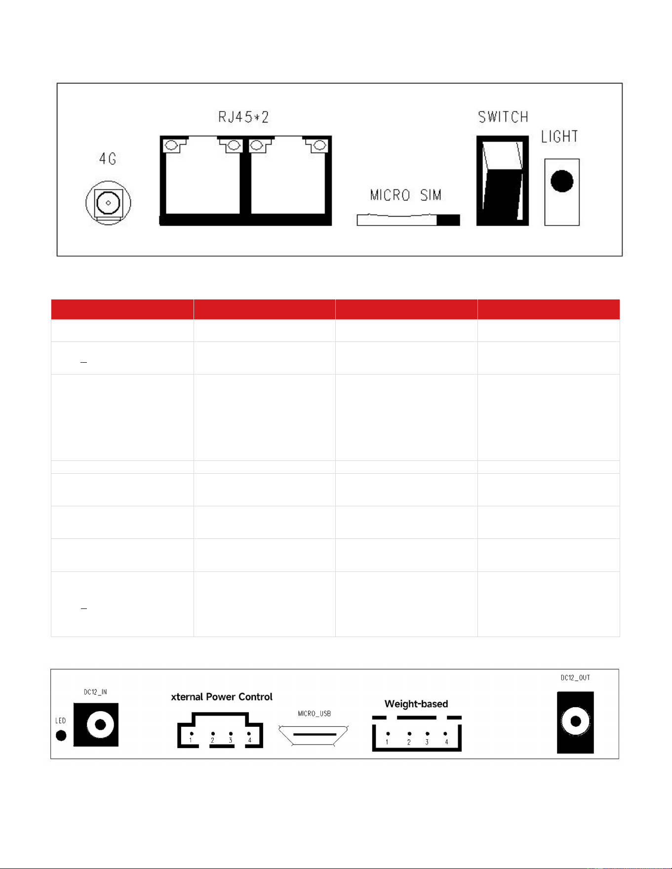
6.2 Side B Interfaces
Silkscreen / Label Name Description Notes
4G 4G antenna 4G antenna connector.
Female connector, standard
wiring.
RJ45 × 2
Ethernet ports Two RJ45 Ethernet ports.
RJ45x2p_12p
MICRO SIM Removable data SIM card
Micro SIM push-push card slot.
Install the card with the
notched corner facing outward
and the chip facing down.
Confirm SIM and carrier
compatibility before
deployment.
SWITCH
Rocker switch
Press the “O” side to power off.
Controls system power on/off.
LIGHT
System status indicator
Off = system not started. Fast
flashing = normal operation.
Slow flashing = main controller
not online.
- 7
XMAI | XM-8600A Industrial Controller User Manual
-
6.3 Side C Interfaces
Silkscreen / Label Name Description Notes
Left 1 - Wi-Fi Antenna Wi-Fi antenna interface
Wi-Fi antenna connector.
Male connector, standard
wiring.
DC12 IN
Main power input
Main controller power input:
DC 12 V. Round DC jack, 5.5
mm / 2.1 mm.
Use the specified 12 V DC
power source.
External Power Control
Single/multiple relay control
12 V switching signal used to
drive a 220 V relay in the
original configuration. Typical
uses: compressor on/off
control; internal fan or cabinet
heater power and switching
control; electric heated door
power and switching control.
HX25418-4WA. For U.S.
installations, verify relay and
load ratings against applicable
local electrical requirements.
Debug Port
Serial debug port
Pin sequence: GND, RX, TX.
Gravity
Gravity sensor interface
UART serial interface, 5 V
power supply. Pin sequence:
RX, TX, GND, 5 V.
4-pin, XH2.54 connector;
approx. 0.10 in pitch.
Type-C
Reserved for high-end face-
recognition configuration
Two vertical Type-C
connectors reserved for
optional configuration.
HX25418-4WA
miniHDMI
Reserved for high-end face-
recognition configuration
One miniHDMI connector
reserved for optional
configuration.
DC12 OUT
12 V power output
Standard-wiring plastic DC
power socket, right-angle
installation. Inner contact
diameter approx. 0.079 in;
outer contact diameter approx.
0.232 in.
DC-005-5A-2.0

- 8
XMAI | XM-8600A Industrial Controller User Manual
-
PART7
7. After-Sales Support
For technical support, please contact XMAI / Xiaomai Retail Technology Co., Ltd.
Support Item Contact
Email
Phone
Website
+1 8165537029
https://xmaivending.com/
Warning:
Changes or modifications to this unit not expressly approved by the party responsible for compliance could void the user’s
authority to operate the equipment.
NOTE:
This device complies with part 15 of the FCC Rules. Operation is subject to the following two conditions: (1) This device may not
cause harmful interference, and (2) this device must accept any interference received, including interference that may cause
undesired operation.
FCC Statement:
This equipment has been tested and found to comply with the limits for a Class B digital device, pursuant to part 15 of the FCC
Rules. These limits are designed to provide reasonable protection against harmful interference in a residential installation. This
equipment generates, uses and can radiate radio frequency energy and, if not installed and used in accordance with the
instructions, may cause harmful interference to radio communications. However, there is no guarantee that interference will not
occur in a particular installation. If this equipment does cause harmful interference to radio or television reception, which can be
determined by turning the equipment off and on, the user is encouraged to try to correct the interference by one or more of the
following measures:
—Reorient or relocate the receiving antenna.
—Increase the separation between the equipment and receiver.
—Connect the equipment into an outlet on a circuit different from that to which the receiver is connected.
—Consult the dealer or an experienced radio/TV technician for help.
The equipment complies with FCC Radiation exposure limit set forth for uncontrolled environment. This equipment should be
installed and operated with minimum distance 20cm between the radiator and your body.