World’s Leading Smart Home Solution Provider
BL3420-P BT Module Datasheet
Module Features
MCU: 32-bit, OTP: 16KB
GPIO: 15 pins, PWM: 8 channels
Operating Voltage: 1.8V ~ 3.6V
RF Features:
Frequency Range: 2.400GHz ~ 2.480GHz
Data Rate: 1Mbps
Modulation: GFSK
Output Power: 8dBm ±2dBm
Receiver Sensitivity: -95 ± 2dBm @ 1M
On-board PCB Antenna
Peripherals:
15x GPIO
8x PWM
4x ADC
1x UART
Operating Temperature: -10℃ to +105℃
Package: Half-hole surface mount, supports SMT placement
Module Dimensions: (13.3 ± 0.2) mm * (21 ± 0.2) mm * (3.4 ± 10%) mm (with
shield)
Applications
Intelligent Transportation
Smart Home/Appliances
Instrumentation
Healthcare
Industrial Automation
Smart Security
Smart Energy
Module Model: BL3420-P
Model
Antenna
Note
BL3420-P
Built-in

World’s Leading Smart Home Solution Provider
Table of Contents
1. Product Overview................................................................................................................................. 3
2. Electrical Parameters........................................................................................................................... 3
2.1 Power Consumption Parameters.............................................................................................3
2.2 Operating Environment...............................................................................................................3
3. RF Parameters........................................................................................................................................4
3.1 Basic RF Parameters......................................................................................................................4
4. Basic Information of BL3420-P........................................................................................................5
4.1 Pin Layout.........................................................................................................................................5
4.2 Pin Definitions.................................................................................................................................5
4.3 Mechanical Dimensions.............................................................................................................. 7
4.5 Usage Instructions.........................................................................................................................7
Version History...........................................................................................................................................8
Copyright Notice....................................................................................................................................... 8
Contact Us ..............................................................................................................................................9
World’s Leading Smart Home Solution Provider
1. Product Overview
The BL3420-P is a BLE module launched by BroadLink, featuring a 32-bit MCU with 15
GPIOs, 8 PWM channels, and 4 ADC interface, utilizing a stamp hole interface, and
powered by a 3.3V single power supply. The module integrates an RF transceiver, MAC,
and baseband processing, supporting data pass-through and can form self-organizing
networks based on BLE. It is widely applicable in smart home devices, medical
instruments, and more.
2. Electrical Parameters
2.1 Power Consumption Parameters
Power consumption parameters are detailed in Table 1.
Table 1: BL3420-P Power Consumption Parameters
Specifications
Min.
Typ.
Max.
Units
VDD
1.8
3.3
3.6
V
VIL (input low voltage)
VSS
-
0.3VDD
V
VIH (input high voltage)
0.7VDD
-
V
VOL (output low voltage)
-
-
0.5
V
VOH (output high voltage)
2.5
-
-
V
RPU (pull-up resistor)
-
69
-
KΩ
RPD (pull-down resistor)
-
-
-
KΩ
Io (output current)
-
10
-
mA
Receiving mode @ 1M
-
12
-
mA
Sleep current
-
2
-
uA
*Note: Actual firmware testing results may vary.
2.2 Operating Environment
Operating environment parameters are detailed in Table 2.
Table 2: BL3420-P Operating Environment
Symbol
Description
Min.
Max.
Units
Ts
Storage temperature
-40
125
℃
World’s Leading Smart Home Solution Provider
Symbol
Description
Min.
Max.
Units
TA
Ambient operating temperature
-10
105
℃
Vdd
Supply voltage
1.8
3.6
V
Vio
Voltage on IO pin
0
3.3
V
3. RF Parameters
3.1 Basic RF Parameters
RF parameters are detailed in Table 3.
Table 3: BL3420-P RF Parameters
Normal RF Condition
Normal
RF
Condition
Parameter
Min.
Default
Max.
Units
Reference
Value
FOP
Frequency range
2400
-
2480
MHz
2400~2480
Specification
BLE 5.2
TX Characteristics
PRF
RF output power
-
8
-
dBm
Note (1)
RX Characteristics
SEN
RX Sensitivity
@PER 30.8% 1Mbps
-
-95
-
dBm
≤-70
FET
Frequency offset range
-250
-
250
KHz
-
Carrier Frequency Offset
FOF
Center frequency offset
-150
-
150
KHz
FD
Frequency drift
-50
-
50
KHz
FDR
Maximum drift rate
-20
-
20
KHz
20KHz/50us
Modulation Characteristics
Delta F1 Avg
225
-
275
KHz
225~275KHz
Delta F2 Max @99.9%
≥185
-
-
KHz
≥185
Delta F2 Avg/Delta F1 Avg
≥0.8
-
-
-
≥0.8
Note: The output power level is determined by the relevant register configuration in the
software.
World’s Leading Smart Home Solution Provider
4. Basic Information of BL3420-P
4.1 Pin Layout
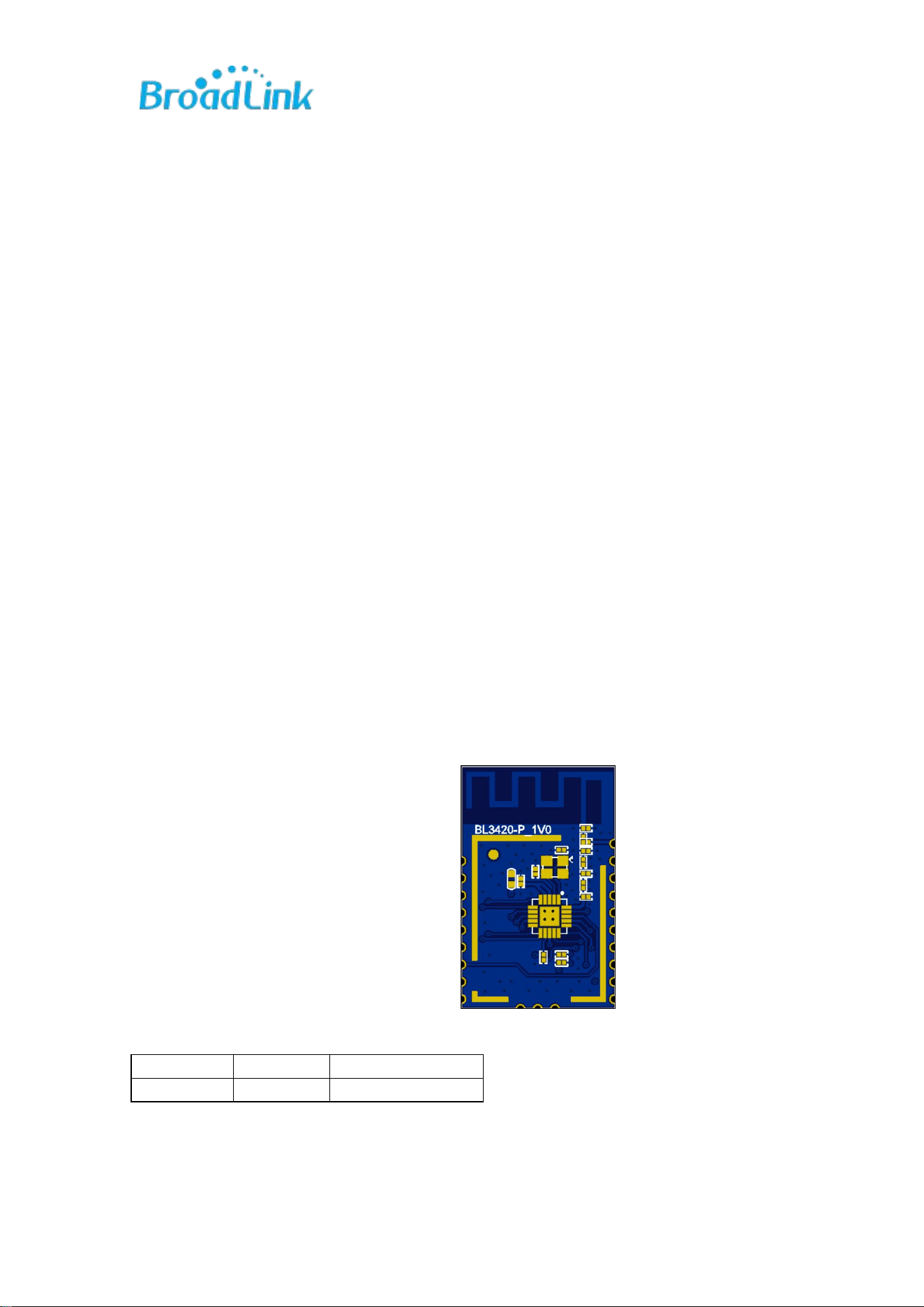
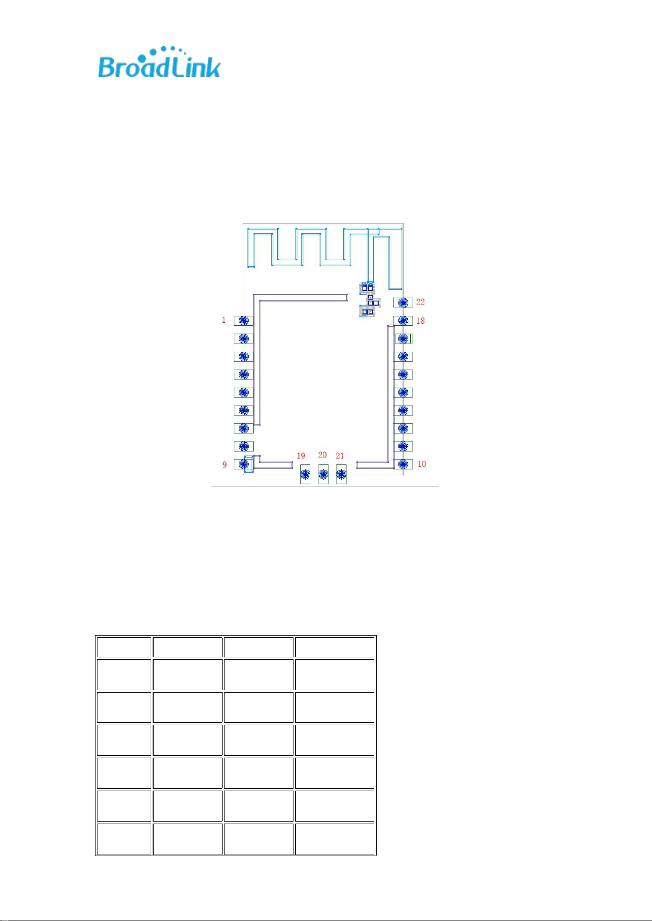
Refer to Figure 1 for pin layout.
Figure 1: BL3420-P Pin Layout
4.2 Pin Definitions
Refer to Table 4 for pin definitions.
Table 4: BL3420-P Pin Definition Notes
PIN
Function 1
Function 2
Function 3*
1
P9
UART_TX
TX_LOG
2
P8
UART_RX
RELAY4
3
P1
PWM1
KEY3
4
P0
PWM0
KEY4
5
P7
PWM7
KEY1
6
P6
PWM6
DD(backlight)
World’s Leading Smart Home Solution Provider
Note:
1. (Panel) Function 3 is mainly applicable to the pin definition of Broadlink own
single-zero-fire panel;
2. The default is to use P5_1 (i.e. P5), located at the PIN21 position;
3. The pins at PIN2 (UART_RX/P8) and PIN15 (P8) are the same pin and can be used
interchangeably. Only one function definition can be selected at both ends.
4. RF_OUT indicates that the external antenna of the module is in use. When the PCB
antenna is currently in use, this port becomes invalid.
7
P21
ADC7/PWM5
ZERO
8
VDD
9
GND
10
NC
11
P20
PWM4
RELAY1
12
P18
PWM2
RELAY2
13
P19
ADC6/PWM3
RELAY3
14
P15
ADC4
RELAY4
15
P8
KEY8
16
NC
---
---
17
P23
PWM7
KEY2
18
GND
19
P2
PWM2
KEY5
20
P4
PWM4
KEY6
21
P5_1
PWM5
KEY7
22
NC
World’s Leading Smart Home Solution Provider
4.3 Mechanical Dimensions
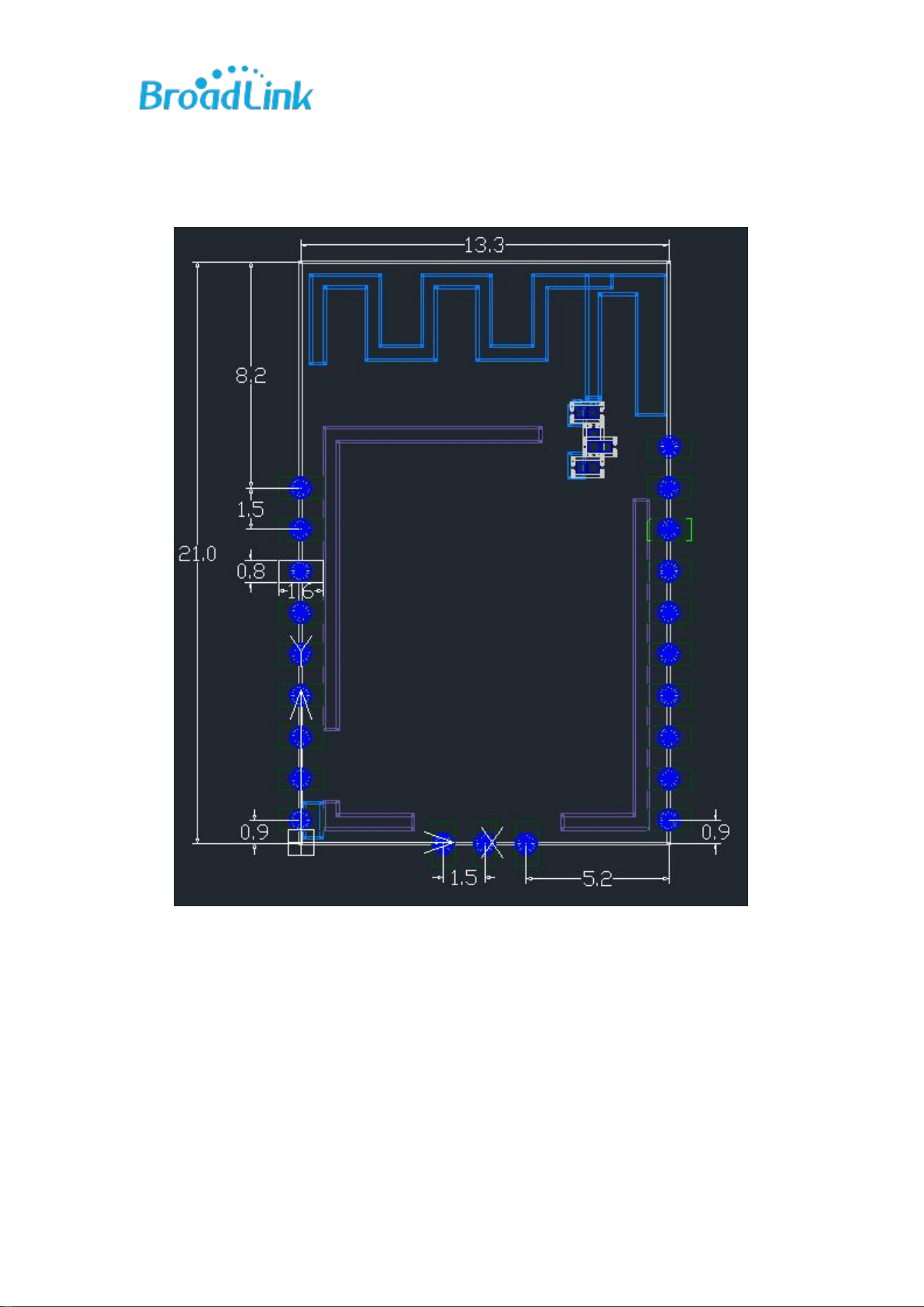
Refer to Figure 2 for module dimensions. Unit: mm.
Figure 2: BL3420-P Module Dimensions
Dimensions: (13.3 ±0.2) mm x (21 ±0.2) mm x (3.4 ±10%) mm (with shield)
4.5 Usage Instructions
1. Ensure there are no metals or components within 30mm around the onboard
antenna. Keep the bottom area clear, avoiding high-speed clock lines and
high-current power lines.
2. For the 3.3VD power supply pin, connect capacitors of 10μF-47μF in parallel
with several 18pF to 100nF capacitors.
World’s Leading Smart Home Solution Provider
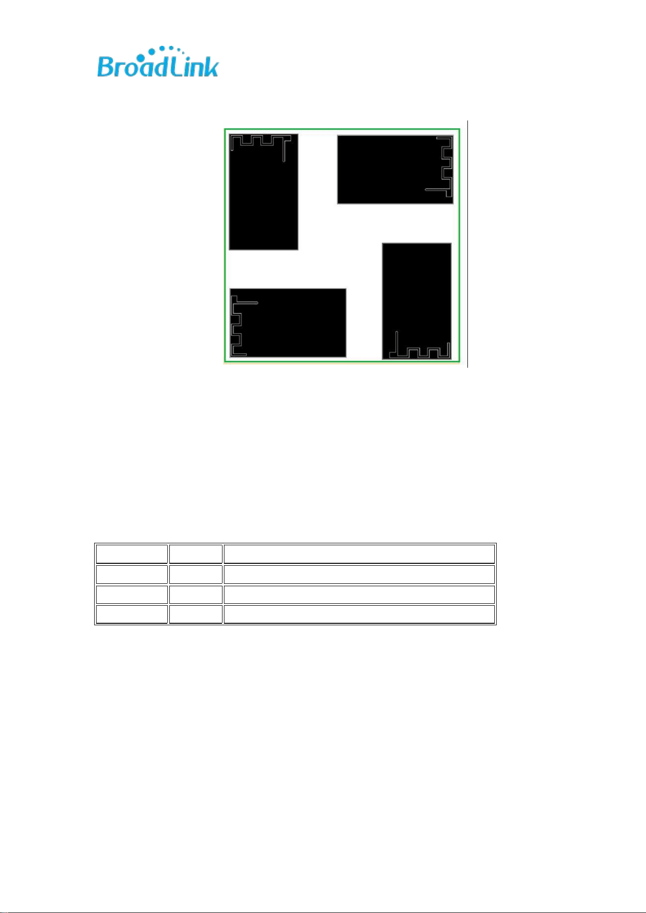
3. The preferred location for the module is shown in Figure 8.
Figure 4: Preferred Location for Module
4. The I2C interface supports both Master and Slave modes, determined by the
firmware version. When in Slave mode, an external pull-up to 3.3VD is
required.
Version History
Date
Version
Description
2026-6-16
1.0
Initial document
2026-7-9
1.1
Parameter update
Copyright Notice
Without permission, it is forbidden to use or copy any part of this manual, especially
trademarks, model names, part numbers, and graphics.
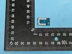
Module
Device PCB

World’s Leading Smart Home Solution Provider
Contact Us
Ms. Zhou
Hangzhou Broadlink Intelligent Technology Co., Ltd.
Address: C Building, Hangzhou AI Industrial Park, No. 57 Jiang'er Road, Binjiang
District, Hangzhou, Zip: 310052
Online Consultation: 0571-85071744-8010
Email: bingqi.zhou@broadlink.com.cn
For more information about Broadlink modules, please visit: www.broadlink.com.cn
List of applicable FCC rules
FCC Part 15.247
Label and compliance information
FCC ID label on the final system must be labeled with “Contains FCC ID:
2ATEV-BL3420-P” or “Contains transmitter module FCC ID: 2ATEV-BL3420-P”.
Information on test modes and additional testing requirements
Contact Hangzhou BroadLink Technology Co., Ltd. will provide stand-alone modular
transmitter test mode. Additional testing and certification may be necessary when
multiple modules are used in a host.
Additional testing, Part 15 Subpart B disclaimer
To ensure compliance with all non-transmitter functions the host manufacturer is
responsible for ensuring compliance with the module(s) installed and fully
operational. For example, if a host was previously authorized as an unintentional
radiator under the Supplier’s Declaration of Conformity procedure without a
transmitter certified module and a module is added, the host manufacturer is
responsible for ensuring that the after the module is installed and operational the
host continues to be compliant with the Part 15B unintentional radiator
requirements. Since this may depend on the details of how the module is integrated
with the host, Hangzhou BroadLink Technology Co., Ltd. shall provide guidance to

World’s Leading Smart Home Solution Provider
the host manufacturer for compliance with the Part 15B requirements.
Note: This equipment has been tested and found to comply with the limits for a Class B
digital device, pursuant to part 15 of the FCC Rules. These limits are designed to provide
reasonable protection against harmful interference in a residential installation. This
equipment generates, uses and can radiate radio frequency energy and, if not installed
and used in accordance with the instructions, may cause harmful interference to radio
communications. However, there is no guarantee that interference will not occur in a
particular installation. If this equipment does cause harmful interference to radio or
television reception, which can be determined by turning the equipment off and on, the
user is encouraged to try to correct the interference by one or more of the following
measures:
—Reorient or relocate the receiving antenna.
—Increase the separation between the equipment and receiver.
—Connect the equipment into an outlet on a circuit different from that to which the
receiver is connected.
—Consult the dealer or an experienced radio/TV technician for help.
FCC Warning
This device complies with Part 15 of the FCC Rules. Operation is subject to the
following two conditions:
(1) This device may not cause harmful interference, and (2) this device must accept
any interference received, including interference that may cause undesired
operation.
NOTE 1: Any changes or modifications to this unit not expressly approved by the
party responsible for compliance could void the user's authority to operate the
equipment.
FCC Radiation Exposure Statement:
This equipment complies with FCC radiation exposure limits set forth for an

World’s Leading Smart Home Solution Provider
uncontrolled environment. End users must follow the specific operating instructions
for satisfying RF exposure compliance.
Note 1: This module certified that complies with RF exposure requirement under
mobile or fixed condition, this module is to be installed only in mobile or fixed
applications.
A mobile device is defined as a transmitting device designed to be used in other than
fixed locations and to generally be used in such a way that a separation distance of
at least 20 centimeters is normally maintained between the transmitter's radiating
structure(s) and the body of the user or nearby persons. Transmitting devices
designed to be used by consumers or workers that can be easily re-located, such as
wireless devices associated with a personal computer, are considered to be mobile
devices if they meet the 20 centimeter separation requirement.
A fixed device is defined as a device is physically secured at one location and is not
able to be easily moved to another location.
Note 2: Any modifications made to the module will void the Grant of Certification,
this module is limited to OEM installation only and must not be sold to end-users,
end-user has no manual instructions to remove or install the device, only software
or operating procedure shall be placed in the end-user operating manual of final
products.
Note 3: The module may be operated only with the antenna with which it is
authorized. Any antenna that is of the same type and of equal or less directional
gain as an antenna that is authorized with the intentional radiator may be marketed
with, and used with, that intentional radiator.
IC WARNING
This device contains licence-exempt transmitter(s) that comply with Innovation,
Science and Economic Development Canada’s licence-exempt RSS(s). Operation is

World’s Leading Smart Home Solution Provider
subject to the following two conditions:
(1) This device may not cause interference.
(2) This device must accept any interference, including interference that may cause
undesired operation of the device.
L’émetteur/récepteur exempt de licence contenu dans le présent appareil est
conforme aux CNR d’Innovation, Sciences et Développement économique Canada
applicables aux appareils radio exempts de licence. L’exploitation est autorisée aux
deux conditions suivantes:
1. L’appareil ne doit pas produire de brouillage;
2. L’appareil doit accepter tout brouillage radioélectrique subi, même si le brouillage
est susceptible d’en compromettre le fonctionnement.
IC Radiation Exposure Statement:
This device and its antenna(s) must not be co-located with any other transmitters
except in accordance with IC multi-transmitter product procedures. Referring to the
multi-transmitter policy, multiple-transmitter(s) and module(s) can be operated
simultaneously without reassessment permissive change.
Cet appareil et son antenne (s) ne doit pas être co-localisés ou fonctionnement en
association avec une autre antenne ou transmetteur.
This equipment complies with IC RSS-102 radiation exposure limits set forth for an
uncontrolled environment. This equipment should be installed and operated with
minimum distance 20cm between the radiator & your body.
Cet équipement est conforme aux limites d'exposition aux rayonnements IC établies
pour un environnement non contrôlé. Cet équipement doit être installé et utilisé
avec un minimum de 20cm de distance entre la source de rayonnement et votre

World’s Leading Smart Home Solution Provider
corps.
This module is limited to OEM installation only and must not be sold to end-users,
end-user has no manual instructions to remove or install the device, only software
or operating procedure shall be placed in the end-user operating manual of final
products. Additional testing and certification may be necessary when multiple
modules are used.
Any changes or modifications not expressly approved by the manufacturer could
void the user's authority to operate this equipment.
The final end product must be labeled in a visible area with the following " Contains
IC: 25062-BL3420P".