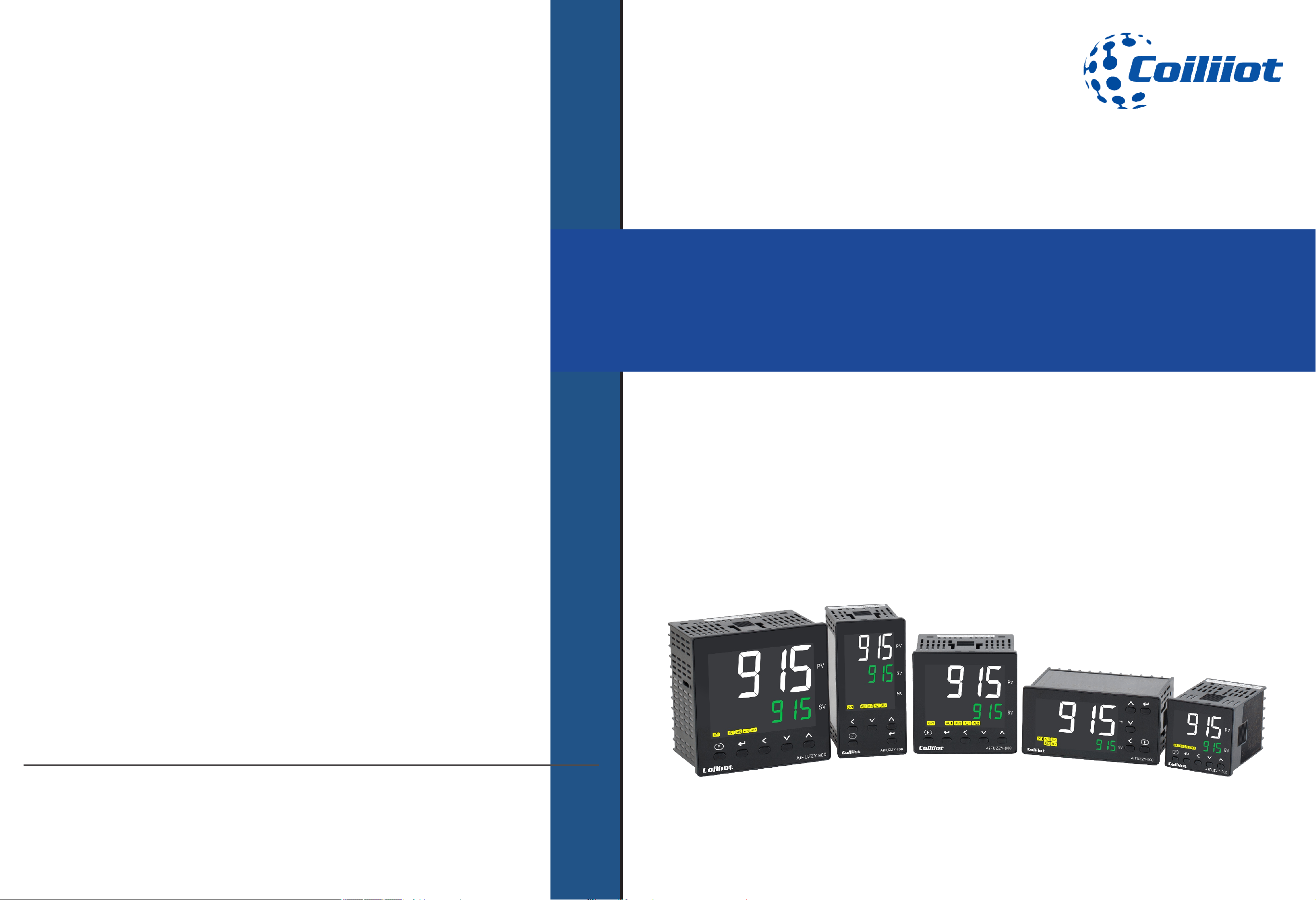
Technical Manual
Version number: EN-V9-01
Thank you for choosing Coiliiot products.
To ensure optimal use of this product, please read the following instructions before use.
Economical PID Temperature Controller
For General Use
AiFUZZY-915/975
Contact Us
Coiliiot LLC
8 THE GRN STE B,
Dover, DE, 19901
(+1)857-565-5912
info@coiliiot.com
https://coiliiot.com

Page
Table of contents
Table of contents
Table of contents .........................................................................................................................1-2
Safety instruction ............................................................................................................................3
Chapter 1 Main features ..................................................................................................................4
Chapter 2 .......................................................................................................5Technical parameter
Chapter 3 Model definition ..............................................................................................................7
Chapter 4 Wiring diagram ..............................................................................................................10
Chapter 5 Panel ...........................................................................................................11 description
Chapter 6 ......................................................................................................12Module instructions
Chapter 7 ................................................................................................... 13Operation Flow Chart
C .............................................................15hapter 8 Instruction of instrument operation method
Chapter 9 ......................................................................................17 Parameter table and function
Chapter 10 Additional functions....................................................................................................29
Page 1/44 pages in total A FUZZY-915/975 9- i Technical Manual_Version number: EN-V 01

Chapter ...........................................................................32 11 Partial application wiring methods
Chapter 1 ...................................................................................................................352 Input Error
Chapter 13 AiFUZZY-975 programming instruction.....................................................................36
Chapter 1 .................................................................404 Dimensions and installation instructions
Page
Table of contents
Table of contents
Page 2/44 pages in total A FUZZY-915/975 9- i Technical Manual_Version number: EN-V 01
Safety Instructions
■Safety Instructions
Page 3/44 pages in total A FUZZY-915/975 : 9- i Technical Manual_Version number EN-V 01
Attention
Do not touch the terminals while the power is on, as this may result in minor
injuries from electric shock.
Do not allow metal objects, conductors, debris (such as installation cuttings), moisture,
or other foreign matter to enter the digital controller, setup tool ports, or the pins on the
Setup Tool cable connectors.
Failure to do so may result in electric shock, short circuits, or malfunction of the
equipment.
Do not disassemble, modify, or repair the product, or touch any internal components.
Failure to follow this may result in electric shock, fire, or equipment failure.
If the output relays are used beyond their life expectancy, contact welding or burning
may occur.
Always ensure the application conditions are considered, and use the output relays
within their rated load and electrical life expectancy.
The life span of the output relays can vary significantly depending on the load and
switching conditions.
Do not use the product in environments exposed to flammable or explosive gases,
as this may lead to injury due to explosion.
This equipment is an open processing controller. Do not use it in a control cabinet where
a fire hazard may exist.
When using more than two open-circuit switches, ensure all switches are turned off
before performing maintenance or inspections to keep the product powered off.

Chapter 1 Main features
■1.Main features
Page 4/44 pages in total
1.1AiFUZZY-915Main features
-Color LCD Display: Features a color LCD screen with white PV font for easy readability from a distance. The side
-illuminated backlight combined with advanced LCD technology delivers a soft and clear display.
-Sleek Design: The ultra-thin panel and large LCD screen are housed in a modern industrial aesthetic shell,
providing an advanced and sophisticated appearance.
-Durable Waterproof Buttons: Equipped with plastic handle waterproof buttons that are sturdy, wear-resistant, and
offer a clear, smooth operating feel.
-Universal Input: Allows selection of thermocouples, thermistors, analog linear voltage, and current input signals
through parameter settings.
-Versatile Output Modules: Offers a variety of output module options, including:
Relay contact switch output module
SSR drive voltage output module
SCR non-contact switch output module
One-way/three-way SCR zero-crossing trigger output module
One-way SCR phase-shift trigger output module
Analog linear voltage and current output module
-High Measurement Accuracy: Provides a measurement accuracy of 0.25 with enhanced resolution for more
precise and stable measurements.
-Advanced AI Adjustment Algorithm: Combines fuzzy control and adaptive PID control with self-setting and self-
learning functions. It automatically learns and remembers features of the controlled object during adjustment to
optimize performance, ensuring control without overshoot or undershoot and achieving excellent results on
complex and challenging control objects.
-Customizable Alarms: Allows free definition of designated alarm ports and alarm methods, supporting up to four
alarm outputs.
-MIO Auxiliary Input: Optionally equipped with external switch signal input, enabling dual temperature set value
switching or RUN/STOP switching.
-Dual PID Control: In addition to standard one-way heating or cooling PID control, it supports dual PID
dual control outputs for heating and cooling, automatically switching based on the set value.
-Rate Limiting: Freely defines rate limiting for temperature rise and drop to ensure controlled and stable
temperature changes.
-Analog Signal Output: Converts the measured value (PV) or set value (SV) into an analog linear current
signal output.
-Comprehensive Power Supply and Isolation: When the instrument has multiple sets of inputs and
outputs, it provides a comprehensive power supply and optoelectronic isolation solution.
-Communication Interfaces: Offers optional RS485 or RS232 communication interfaces supporting the
Modbus-RTU protocol, featuring a fast 10ms communication response, unlimited writing cycles, and no
concerns about communication write lifespan.
A FUZZY-915/975 9- i Technical Manual_Version number: EN-V 01

Chapter 1 Main features
1.2 AiFUZZY975 Main features
-Enhanced Program Control: Builds upon the AiFUZZY915 universal multi-functional temperature
controller by adding an 80-segment program control function. Ideal for applications that require
automatic set value adjustments based on specific time rules
-80-Segment Programming: Enables the setting of rise and fall slopes for any set value. Includes
programmable commands such as jump, run, pause, and stop, allowing modifications to the program
during operation for greater flexibility and control.
-Advanced Power Failure Handling: Features a power failure processing mode, measured value startup
function, and preparation function. These enhancements ensure efficient and reliable program
execution even in the event of power interruptions.
-Multiple PID Parameter Sets: Offers three sets of PID parameters. Through programming, each
temperature stage can utilize a different PID set, addressing the need for varied PID parameters to
achieve optimal control across different temperature ranges.
-.Simplified Program Setup: The 80-segment program can be configured to create a single temperature
curve, with the option to mask unnecessary segments. This simplifies the program setup process,
making it more user-friendly.
-Grouping Feature: Allows the division of the 80-segment program into 4 or 8 groups. This facilitates the
pre-programming of multiple temperature curves, enabling quick and easy selection of the desired curve
during operation.
-Backward Compatibility: Incorporates all functions of the AiFUZZY915. When the program setting
function is disabled, the AiFUZZY975 seamlessly operates as a standard AiFUZZY915 temperature
controller, ensuring versatility and ease of transition.
Page 5/44 pages in total A FUZZY-915/975 9- i Technical Manual_Version number: EN-V 01
-Wireless Communication: Connects with the Coiliiot series wireless communication module to enable
various wireless transparent network transmission methods such as TCP, as well as Internet cloud
communication and mobile app integration.
-Self-Healing Power Supply: Utilizes a self-healing circuit design that automatically cuts off power to
protect the instrument in case of overvoltage or undervoltage. It automatically restores normal power
supply when the voltage returns to normal.
Chapter 2 Technical Parameter
■2.Technical Parameter
Page 6/44 pages in total A FUZZY-915/975 9- i Technical Manual_Version number: EN-V 01
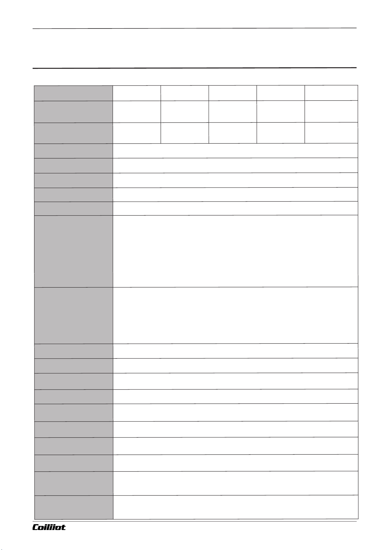
Ty
pe
G - t
y
p
e p
ane
l
D - typ
e p
an
el
A - t
y
pe p
a
nel
E - ty
p
e p
a
n
e
l
F - type pa
nel
P
ane
l Si
z
e (
W
i
dt
h * H
e
i
g
ht
)
48
*
48 mm
1.8
9*
1
.
8
9 i
n
7
2
*
7
2 m
m
2
.
8
3
*
2.
83 in
96*
9
6 mm
3.7
8*3
.
78 i
n
4
8
*
96 m
m
1.
8
9
*
3
.7
8 in
9
6*4
8 m
m
3
.6
2
*
1.
77 in
D
rill G
ap (
Wid
t
h * H
e
ig
ht)
4
5
*
4
5 m
m
1
.
77
*
1.7
7 in
6
8*
6
8 m
m
2
.
6
8
*
2
.
68 in
9
2
*
92 m
m
3
.
62*
3
.6
2 i
n
4
5*
9
2 m
m
1
.7
7
*3.
62 in
92
*
4
5 m
m
3.6
2*
1
.
77 i
n
Mo
un
tin
g Typ
e
Bu
il
t
-i
n p
a
ne
l mou
n
t
i
ng
P
o
w
er sup
p
l
y
AC
100
~24
0
V 5
0/
6
0
Hz
;
o
r DC
12
~
24V
Volt
ag
e R
a
n
g
e
85
%
~ 1
1
0
%o
f th
e r
ated p
o
we
r v
o
l
t
a
ge
P
o
w
e
r c
o
n
s
um
pti
o
n
A
C1
0
0~2
4
0
V
: 5
V
A OR D
C1
2~2
4
V: 3
.5
VA
D
is
p
l
a
y
LCD d
i
s
p
l
ay (
w
h
it
e f
o
r P
V
, gr
e
e
n fo
r SV
, l
ight o
r
an
ge for in
d
ic
at
o
r)
I
n
p
ut
T
he
rmoco
up
l
e i
n
put
: K
,S,
R,
E
,
J,T
,B
,
N,W
Re
3
-WRe2
5,WRe
5
-WR
e2
6
,
et
c
The
rmal re
si
s
tanc
e i
n
put
: C
u
50, Pt
1
00
Li
ne
ar c
u
rrent i
n
pu
t: 0
-2
0
m
A, 4
-
20m
A
Li
ne
ar v
o
l
tage i
n
p
ut
: 0-5
V,1
-5
V
,
0
-
1
0
V,2-
10V,0
-
20
V
,
0-2
0
mV,0-
60m
V,
0
-7
5
m
V
,
0
-
10
0
mV
,
0-5
00m
V,1
0
0-5
0
0
m
V,e
tc
Mea
su
rem
ent Ran
ge
K: (
-5
0
~
13
0
0
°
C / -58
~
237
2
°F) S
: (
-5
0
~1
700
°
C / -5
8~3
0
92°F) R
: (
-
50
~
170
0
°C / -
58~
3
0
92
°
F
)
T
: (
-
20
0
~
35
0°C / -
32
8
~
66
2
°
F
) E: (
0
~
800
°C / 3
2
~
1
4
7
2°F
) J: (0~1
0
00
°
C / 32~1
832
°
F
)
B
: (20
0~
1
8
0
0
°C / 392
~32
7
2
°F
) N: (
0
~
130
0
°C / 3
2
~2
3
7
2°
F
)
Cu
50: (
-
50~
150°
C / -
5
8~3
0
2°F
) Pt10
0
: (
-2
0
0~6
0
0°
C / -3
2
8
~11
1
2°F)
L
in
ea
r Sc
al
e
: -
9
9
9
9~
3
2000 (
u
s
e
r d
ef
i
n
e
d)
D
ec
im
a
l P
o
i
nt P
os
it
i
o
n
in
g
00
0
0, 00
0.
0, 0
0.0
0, 0
.0
0
0 (
a
djus
t
ab
l
e b
a
se
d on p
ara
me
ter
s
)
Sam
pl
in
g Ac
cu
ra
cy
±
0.
2
5%
FS
Sam
pl
in
g Freq
uen
cy
1
0 ti
m
es p
er s
e
con
d; wh
e
n d
i
git
al f
i
lt
e
r
i
ng i
s s
et to I
NF=0
, re
sp
o
nse t
im
e is 0.
5 sec
o
nd
s
Co
n
trol M
et
h
od
O
N/O
F
F con
trol, A
I FUZ
Z
Y a
l
go
ri
thm
, P
V t
r
ack
i
ng a
n
d SV v
a
lu
e s
e
tt
in
g
Co
ntrol R
a
n
g
e
0.
1
~
3
0
0
.0 s
e
co
nd
s
Re
lay O
u
t
p
u
t
5
A/
250V
A
C OR 5A
/
3
0VD
C
S
S
R D
r
i
ve V
o
l
t
a
g
e O
ut
p
u
t
12V
DC 5
0mA m
a
x (us
ed to d
rive SS
R rel
a
y)
SCR N
on-c
o
n
tact Ou
tp
ut
0
.2
A (c
ont
in
u
ou
s
), 2
A (20m
s pu
ls
e, 5
s p
e
riod) 100
-2
4
0
V
A
C
SCR
Tr
i
g
g
er Ou
tpu
t
Dua
l
-
di
r
e
ct
i
on
a
l S
CR t
rigger, 5
~
5
0
0
A, w
i
t
h 2 si
ng
le
-
d
i
r
ect
io
n S
C
R co
nne
ct
i
o
n
s or cont
r
o
ll
ab
le
SCR powe
r mo
d
u
l
e
s
.
L
i
nea
r C
u
rrent
/V
o
l
tag
e
O
u
tp
u
t
0-
20m
A, 4
-
20m
A ad
j
us
t
a
ble (o
utp
u
t vol
t
a
g
e≥ 10
.5
V
)
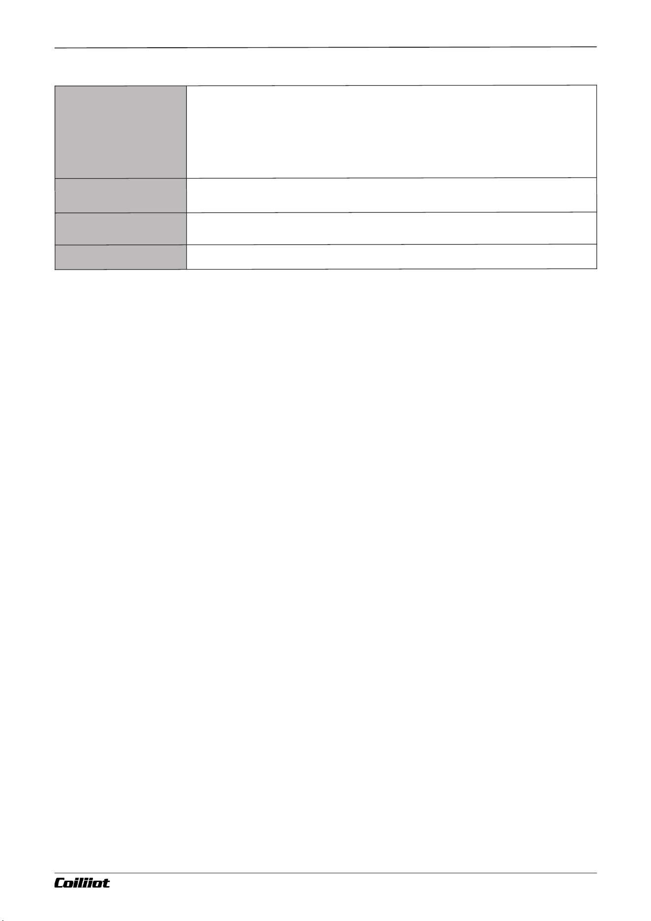
Chapter 2 Technical Parameter
Page 7/44 pages in total A FUZZY-915/975 9- i Technical Manual_Version number: EN-V 01
E
l
ect
ro
m
agn
et
i
c
C
om
pa
tib
il
ity
El
ect
r
o
ma
gne
tic c
o
m
p
a
t
ib
il
i
ty com
pl
ie
s w
it
h I
E
C6
10
0
0
-
4
-
4 (e
l
ec
trica
l f
as
t tr
a
ns
ie
nt b
u
r
s
t
) at
6K
V/5K
Hz
, IE
C6
100
0
-4
-
5 (s
ur
g
e i
m
m
un
it
y
) a
t 6
KV and 1
0
V
/
m hi
gh
-f
requ
en
cy el
e
c
tr
o
m
ag
n
e
t
i
c
fi
e
ld i
nt
e
rf
e
r
en
ce
. Un
der t
hes
e c
on
d
it
i
on
s, t
h
e i
ns
trum
ent do
e
s n
ot e
xp
e
rien
ce c
ras
hes o
r
i
n
correc
t I/O o
p
e
r
at
i
o
ns
, a
nd t
h
e me
as
ur
em
e
n
t v
al
u
e fluct
u
at
i
on
s d
o not ex
ce
ed ±
5
% of t
he
me
as
ur
e
d ra
ng
e
.
I
s
o
l
ation Vo
lt
a
g
e
I
np
u
t/o
u
tput
, p
ow
er o
ut
pu
t
/
co
nt
rol mod
ul
e: ≥2
300
V
D
C; si
gn
a
l ter
m
i
na
l
s b
et
w
een pha
se
-to
-
p
has
e s
i
gn
als ≥6
0
0
V
DC
O
pera
t
ing Temp
er
a
tur
e
-
10~5
5°C (
14~1
3
1°F) (no c
o
nd
e
ns
at
i
on
, no ice f
o
r
m
a
t
i
o
n
), hu
mid
i
t
y
: 2
5
~
8
5
%R
H
S
t
o
r
ag
e
Tem
p
e
r
at
ur
e
25
~
65°
C (-
1
3~
1
4
9°F
) (
n
o c
ond
e
n
s
at
i
on
, no i
ce f
orm
at
i
o
n
), h
um
i
d
i
t
y
: 2
5
~8
5
%
R
H
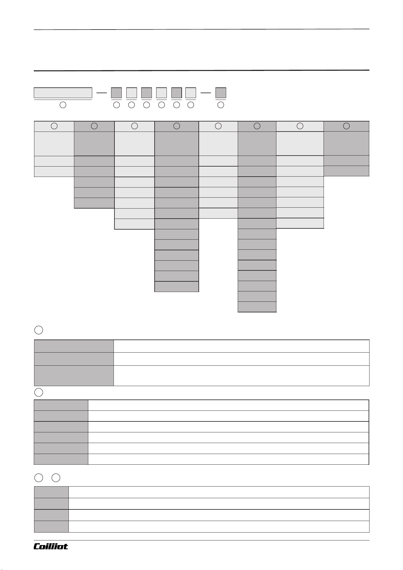
Chapter 3 Model definition
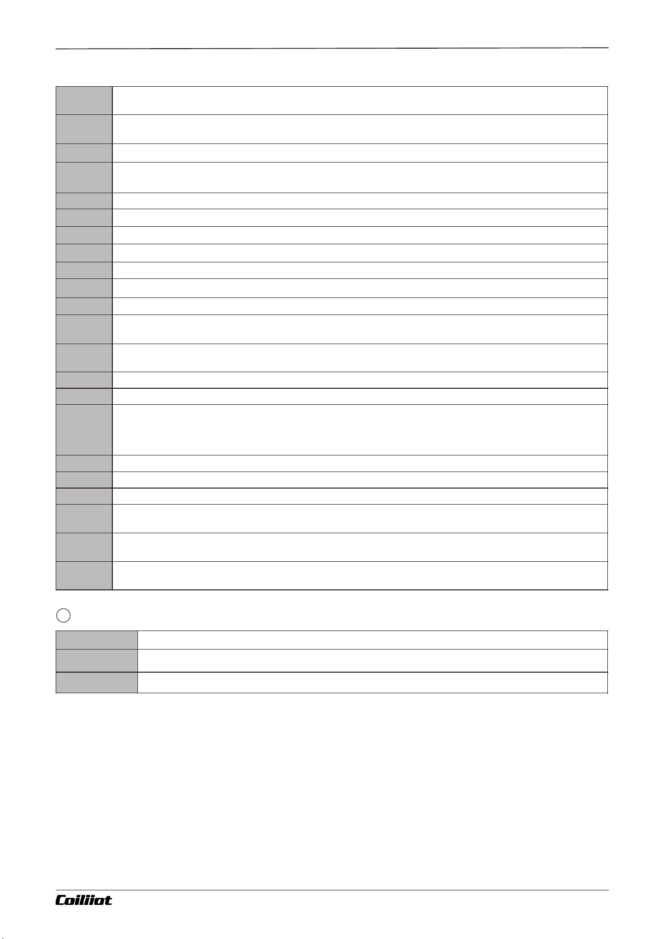
■3.Model definition
Code
Description
N
None
I2
Switch/frequency signal input, suitable for external contacts or frequency signal input
I3
Analog input 4-20mA/0-20mA
Module Code Reference Table
Code
Description
AiFUZZY915
Coiliiot Advanced PID Temperature Controller For Industrial Use
AiFUZZY975
Coiliiot Advanced PID Temperature Controller For Industrial Use
(AiFUZZY975 is based on AiFUZZY915, added with an 80-segment program control function)
Indicates the size of the meter
Model
Panel size
G
D
E
F
A
Model
AiFUZZY915
AiFUZZY975
MIO Auxiliary
input port
N
I2
I3
I4
V5
V12
V24
OUTP Control
output
N
R1
Q1
W1
W2
X2
X5
X8
K1
K3
K5
K6
Q7
AUX
Control
output
N
R1
R2
R3
Q1
Q2
W1
W2
X2
X5
X8
K1
V5
V12
V24
COMM
Communication
Interface
N
S
S2
S4
V5
V12
V24
ALM
Alarm output
N
R1
R2
R3
Q1
Q2
Meter power
supply
N
D
8
1
2
3
4
5
6
7
1
2
3
4
5
6
7
8
2
1
3 7
Page 8/44 pages in total A FUZZY-915/975 9- i Technical Manual_Version number: EN-V 01
Code
Description
G
Panel size 48*48mm/1.89*1.89 in (width*height), drill gap 45*45mm/1.77*1.77 in
D
Panel size 72*72 mm/2.83*2.83 in (width*height), drill gap 68*68 mm/2.68*2.68 in
E
Panel size 48*48mm/1.89*1.89 in (width*height), drill gap 45*45mm/1.77*1.77 in
F
Panel size 48*48mm/1.89*1.89 in (width*height), drill gap 45*45mm/1.77*1.77 in
A
Panel size 48*48mm/1.89*1.89 in (width*height), drill gap 45*45mm/1.77*1.77 in
~
Chapter 3 Model definition
Indicates the power supply power supply
8
I4
Analog input 4-20mA/0-20mA, with 24VDC power supply output (provides power for external transmitters)
R1
Single channel relay normally open/normally closed contact output module, module capacity:
250VAC/3A,30VDC/3A
R2
Dual channel relay normally open contact output module, module capacity: 250VAC/3A,30VDC/3A
R3
Single channel relay frequently open+normal closed contact switch output module, module capacity: 250VAC/3A,
30VDC/3A
Q1
Single channel SSR drive output module, 12VDC/50mA
Q2
Dual channel SSR drive output module, 12VDC/50mA
W1
Normally open isolated non-contact voltage output module, capacity: 100-240VAC/0.2A
W2
Normally closed isolated non-contact voltage output module, capacity: 100-240VAC/0.2A
X2
0-20mA/4-20mA isolated programmable linear current or voltage output module
X5
0-5V/1-5V isolated programmable linear current or voltage output module
X8
0-10V/2-10V isolated programmable linear current or voltage output module
K1
Single-channel "burn-out-proof" SCR zero-crossing trigger output module. Each channel can trigger a 5–500A
bidirectional SCR or two anti-parallel, single-direction SCRs.
K3
Three-channel "burn-out-proof" SCR zero-crossing trigger output module. Each channel can trigger a 5–500A
bidirectional SCR or two anti-parallel, single-direction SCRs.
K5
220VAC “burn-out-proof” single-channel SCR phase-shift trigger output module
K6
380VAC “burn-out-proof” single-channel SCR phase-shift trigger output module
Q7
A built-in SSR (solid-state relay) module wired in parallel with the instrument’s internal power supply. It directly
outputs the instrument’s input voltage—if the supply is 220V, it outputs 220V; if the supply is 110V, it outputs 110V.
Suitable for small loads up to 1.5A at 220V (customization required).
S1
Optical isolation RS485 communication interface module
S2
Optical isolation RS232 communication interface module
S4
Optical isolation with power RS485 communication module
V5
Non-isolated 5V DC voltage output module for external transmitters or other circuits, with a maximum current
output of 50mA.
V12
Isolated 12V DC voltage output module for external transmitters or other circuits, with a maximum current output
of 50mA.
V24
Isolated 24V DC voltage output module for external transmitters or other circuits, with a maximum current output
of 50mA.
Page 9/44 pages in total A FUZZY-915/975 9- i Technical Manual_Version number: EN-V 01
Code
Description
N
100~240VAC power supply
D
12-24VDC power supply
Chapter 4 Wiring diagram
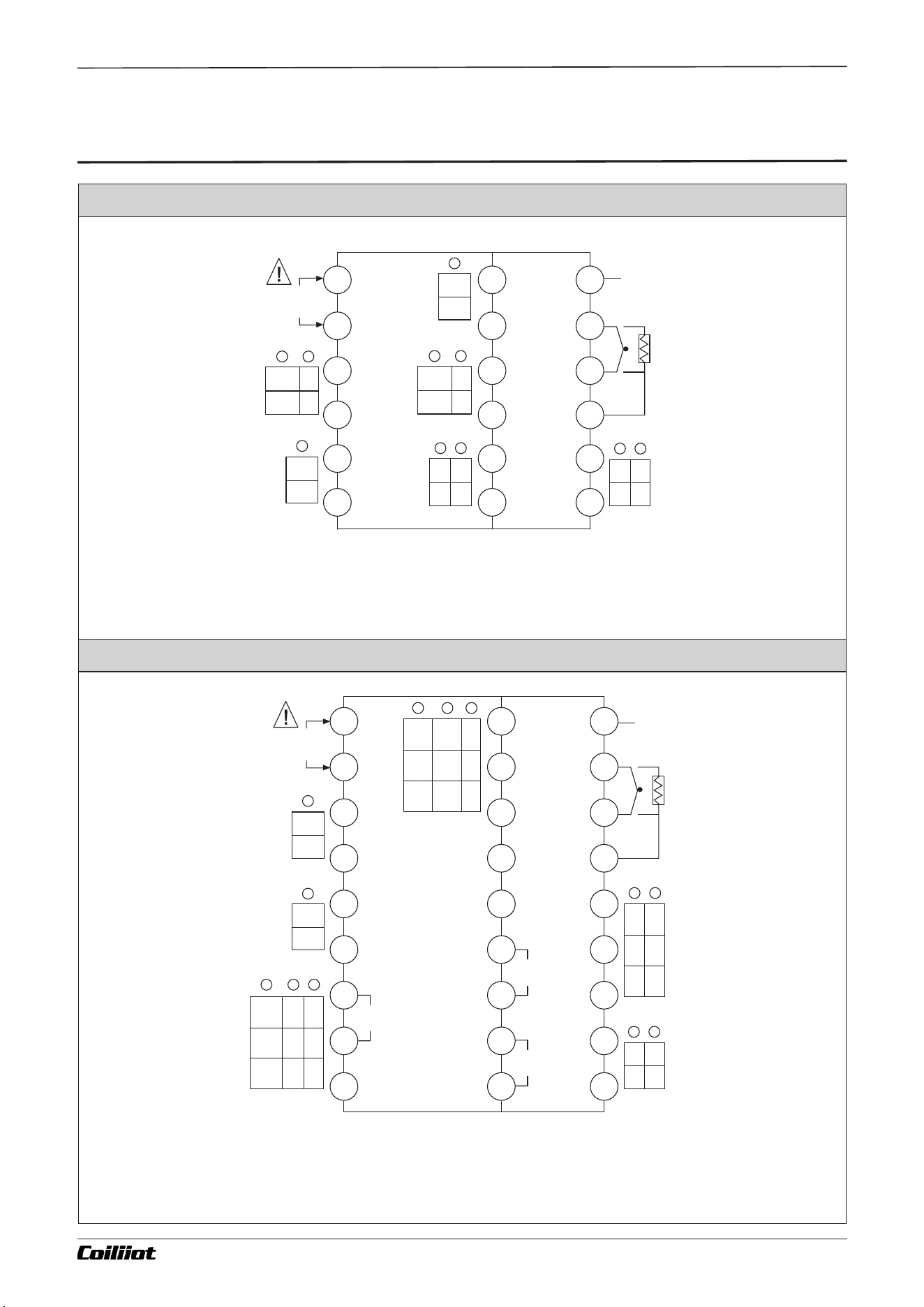
■4.Wiring diagram
Note:
-For linear voltage ranges below 1V, use terminals 11(-) and 12(+) for input.
- For 0–5V and 1–5V signals, use terminals 10(+) and 11(-).
- For 4–20mA linear current input, connect an external 250Ω high-precision resistor to convert it into a 1–5V voltage
signal, then input it through terminals 10(+) and 11(-).
- If using a two-wire 4–20mA transmitter, select the I4 module on the MIO port, then connect the transmitter signal
line to terminal 16 and the transmitter’s 24V positive supply line to terminal 15.
Note:
-For linear voltage ranges below 1V, use terminals 8(-) and 9(+) for input. For 5-10V signals, use terminals 7(+) and 8(-).
-For a 4-20mA linear current input, connect an external 250Ω high-precision resistor to convert it into a 1-5V
voltage signal, and then input it through terminals 7(+) and 8(-).
-If using a two-wire 4-20mA transmitter, select the I4
module on the MIO port. Connect the transmitter’s signal line to terminal 11 and the transmitter’s 24V positive power
line to terminal 12.
G Type panel (48×48mm)
D Type panel (72×72mm)
Page 10/44 pages in total
COM
COM
NO
A
B
NO
_
+
+
_
+
V
+
_
_
+
+
COMM
MIO
AL1
AL2
OP1
AU1
0-5V
1-5V
A
B
B
IN
+
POWER
1
2
3
4
5
6
13
14
15
16
17
18
7
8
9
10
11
12
COM
NO
COM
NO
_
+
COM
COMCOM
NO
NONO
NCNO
A
B
NC
G1
G2
_
_
_
_
+
+
+
V
+
+
+
_
COMM
MIO
AU2
AUX
OP1
AU1
IN
+
G1
G2
SCR trigger 1
1
2
3
4
5
6
7
8
9
POWER
COM
NO
AL1
AL2
COM
NO
19
20
20
22
23
24
25
26
27
G1
G2
SCR trigger 2
G1
G2
SCR trigger 3
10
11
12
13
14
15
16
17
18
+
0-5V
1-5V
_
+
A
B
B
A FUZZY-915/975 9- i Technical Manual_Version number: EN-V 01
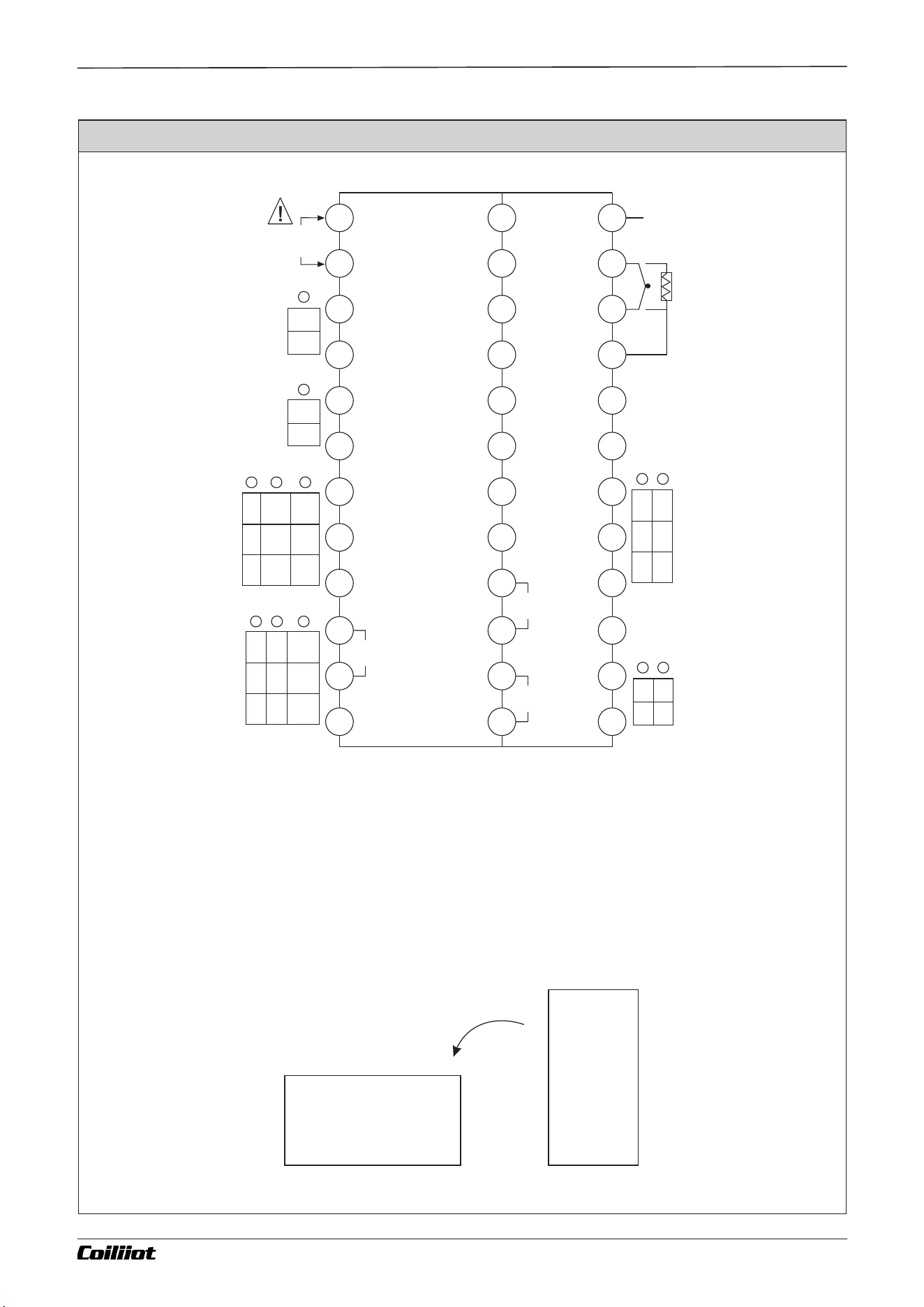
Note1:
- For linear voltage ranges below 1V, use terminals 14(-) and 15(+) for input.
- For 0–5V and 1–5V signals, use terminals 13(+) and 14(-).
- For a 4–20mA linear current input, connect an external 250Ω high-precision resistor to convert the current into a
1–5V voltage signal, then input it through terminals 13(+) and 14(-).
- If using a two-wire 4–20mA transmitter, select the I4 module on the MIO port, then connect the transmitter’s signal
line to terminal 21 and the transmitter’s 24V positive supply line to terminal 20.
Chapter 4 Wiring diagram
E,F,A Type panel (48×96mm/96×48mm/96×96mm)
Page 11/44 pages in total
COM
COMCOM
NO
NO
NO
NC
NO
NC
G1
G2
_
_
+
+
+
AU1
AUX
OP1
AU2
25
26
27
28
29
30
31
32
33
34
35
36
13
14
15
16
17
18
19
20
21
22
23
24
1
2
3
4
5
6
7
8
9
10
11
12
A
B
+
_
COMM
COM
NO
AL1
AL2
COM
NO
POWER
+
0-5V
1-5V
_
+
A
B
B
_
_
V
+
+
MIO
IN
+
G1
G1
G1
G2
G2
G2
SCR trigger 3
SCR trigger 2
SCR trigger 1
Note2:
This wiring diagram is oriented for A and E type panels. For F type panels, which are horizontal, rotate the
diagram 90° counterclockwise for proper viewing. The terminal numbering remains the same.
A FUZZY-915/975 9- i Technical Manual_Version number: EN-V 01
Chapter 5 Panel description
■5.Panel description
Page 12/44 pages in total
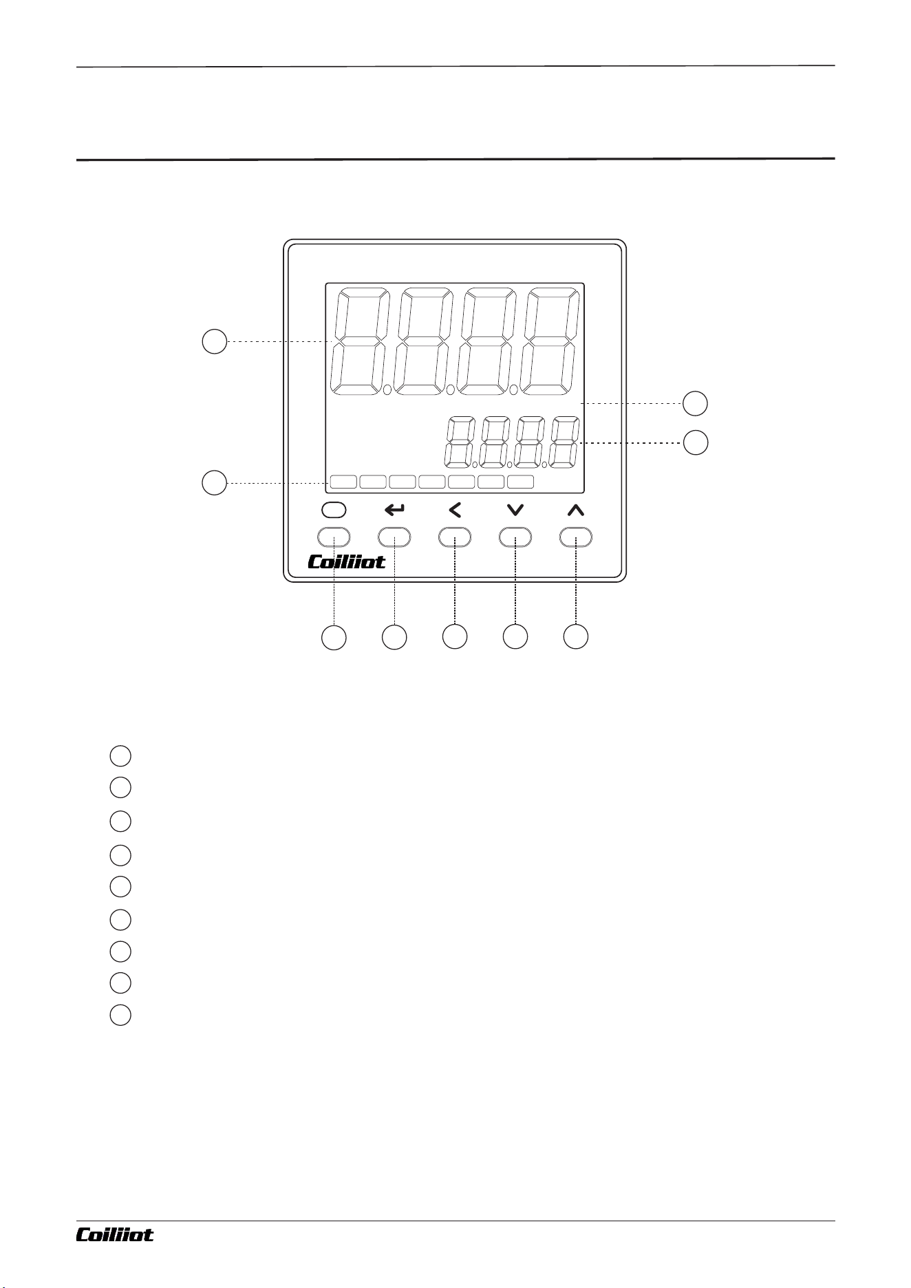
PV Primary Display Window (Displays measured values, parameter names, etc.)
SV Secondary Display Window (Displays set values, parameter values, etc.)
Output indicators:OP1,OP2,AL1,AL2,AU1,AU2,PAR indicators.
Temperature Display Unit (no display for linear analog signal input).
Parameter key: Entry / exit parameter settings.
Return key: confirm and switch to the next parameter.
Data shift key (Also as manual/automatic switching and program setup key)
Data decrease key(Also as run key).
Data increase key(Also as stop key).
1
2
3
4
5
6
7
8
9
1
2
3
9
8
PV
SV
F
AiFUZZY-900
ºFºC
OP1 OP2
AL1 AL2
AU1 AU2
PAR
4
5
6
7
A FUZZY-915/975 9- i Technical Manual_Version number: EN-V 01

Chapter 6 Module instructions
■6.Module instructions
AiFUZZY-915 / AiFUZZY-975 Modules Overview
The AiFUZZY-915 / AiFUZZY-975 instruments can be configured with up to five optional function modules. By
installing different modules, various output specifications and functional requirements can be met.
Auxiliary Input (MIO):
Functions as an extended input, event input, feed output, or extended output function.
- I4 Module: Internal 24V supply in series, dedicated to 4–20mA two-wire transmitter input.
- I3 Module: Standard 4–20mA input without the internal 24V supply.
- I2 Module: Switch signal event input, enabling external switches to toggle between dual setpoints (SP1/SP2) or
RUN/STOP modes.
- V Module: DC voltage output module for external transmitters or other circuits.
Main Output (OUT):
Used for ON-OFF control output, FPID (PID+FUZZY) intelligent control output, or for transmitting measured/set
values.
- R Module: Relay contact output
- Q Module: SSR drive voltage output
- W Module: SCR non-contact output
- X Module: Linear current or linear voltage output
- K Module: SCR zero-cross or phase-shift trigger output
Alarm Output (ALM):
Used for alarm output functions.
- Installing an R module (R1) provides an AL1 relay alarm output.
- Installing R2 provides AL1 + AL2 relay alarm outputs.
Auxiliary Output (AUX):
Serves as the second output for dual PID heating/cooling control or as an alarm output.
- Compatible with R, Q, X, K (only K1), and V modules.
Communication Interface (COMM):
Used for RS485 or RS232 communication or PV value transmission.
- S Module: Communication module (RS485/RS232)
- V Module: DC voltage output module for external transmitters or other circuits.
Note: Modules are soldered to the PCB and configured at the factory based on the user’s order specifications. All
relevant parameters are set correctly before shipment.
Page 13/44 pages in total A FUZZY-915/975 9- i Technical Manual_Version number: EN-V 01
Chapter 7 Operation Flow Chart
■7.Operation Flow Chart
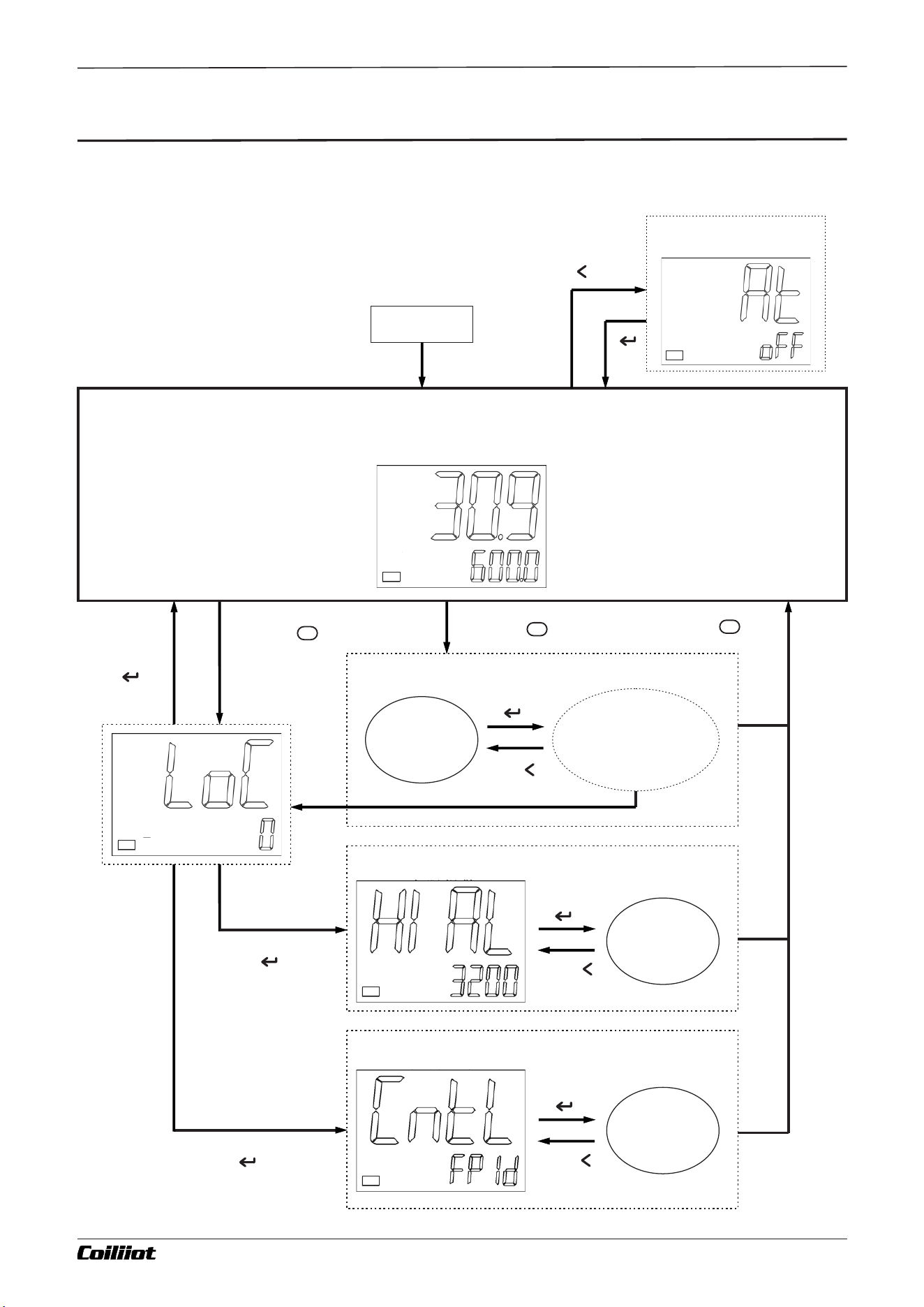
7.1 display status and basic operation flow chart
Page 14/44pages in total
上限报警
控制方式
2 Sec
Set At=ON to start
Auto Tuning
OP1
POWER ON
Basic display status
OP1
PV measured value
SV Set value
F
F
If there are no field parameters,
then press key for 2 seconds
F
2 Sec
If LOC≠800
or 801,
press key
Field parameter
Press
for 2 seconds
Next field parameter
(up to 8 field parameters)
Field
parameter
OP1
Set LOC=800, then
press key
OP1
OP1
Set LOC=801, then
press key
Press
for 2 seconds
Function parameter
The next
parameter
The next
parameter
Control parameters
A FUZZY-915/975 9- i Technical Manual_Version number: EN-V 01
If there are no field parameters,
then press key for 2 seconds
Press
for 2 seconds
Chapter 7 Operation Flow Chart
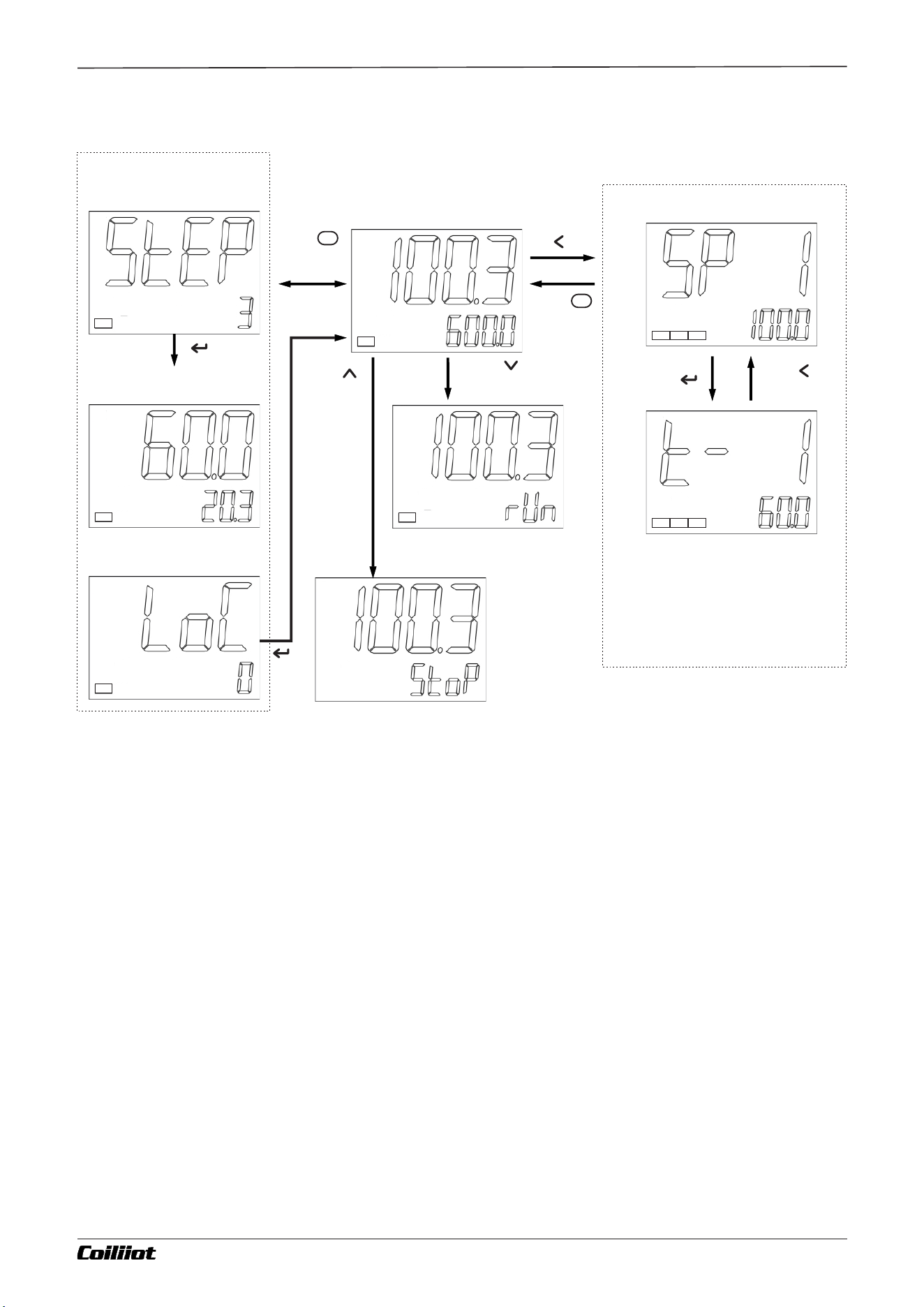
7.2 Program Settings flow chart (AiFUZZY-975 only)
Page 15/44 pages in total
Current curve group number
.
.
.
.
.
.
.
.
.
.
.
.
Field parameter
Basic display status
Press
for
2 Seconds
F
OP1
OP1
OP1
Program setting status
OP1
Supports up to 80 program segments.
You can define the number of
segments using PrSn to remove
unnecessary segments.
OP1
OP1
OP1
AL1 AL2
OP1 AL1 AL2
Briefly displays the "run" symbol, then the
instrument restarts to its normal operating
state.
The instrument is in the "StoP" state.
Current program segment
(Current running segment No.3)
Set the time for 60.0 min,
has run for 20.3 min
A FUZZY-915/975 9- i Technical Manual_Version number: EN-V 01
Press
for 2 seconds
F
Press
for
2 Seconds
Press
for 2 Seconds
Chapter 8 Instruction of instrument operation method
■8.Instruction of instrument operation method
Page 16/44 pages in total
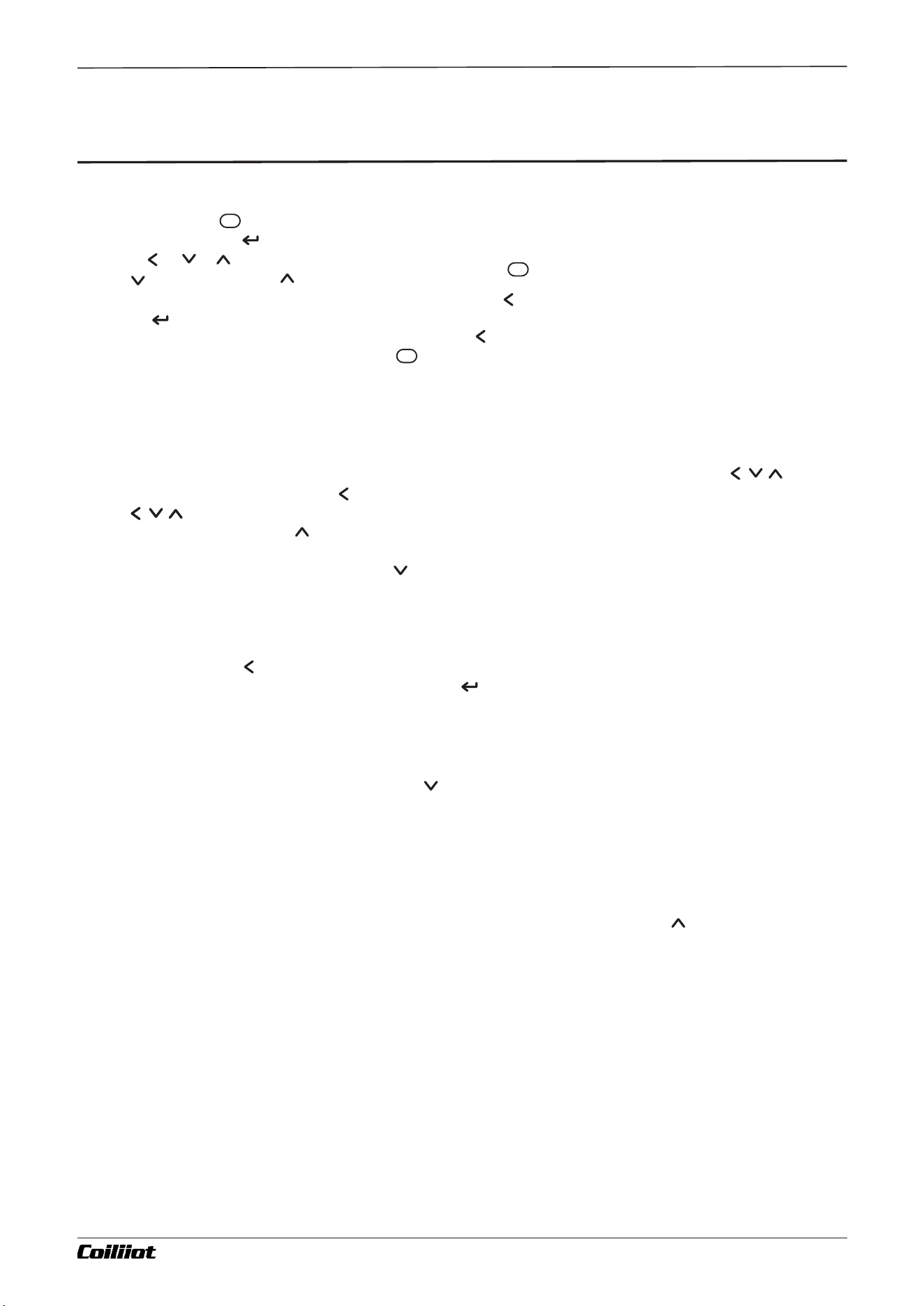
8.1 Parameter Setting
In the basic display state:
•Press and hold the key for about 2 seconds to enter the parameter setting mode.
•If LOC=800, press the key to access the function parameter settings.
•Use the , , , etc., keys to directly modify parameter values.
•Press to decrease and to increase values. Holding the keys enables faster adjustments.
•To navigate directly to a specific digit for editing, press the key, then adjust as needed.
•Press the key to save changes and move to the next parameter.
•To return to the previous parameter, press and hold the key for over 2 seconds.
•Exit to the basic display state by holding the key for 2 seconds.
8.2 Set Value Setting
For AiFUZZY915/975 instruments operating in fixed-point control mode (when Prsn=0 for the 975),
the following applies:
•If Srun=HOLD, you can directly modify the set value in the basic display state by pressing the , , keys.
•If Srun=run, you must first press the key to enter the set value modification state. After that, you can
use the , , keys to adjust the set value. Additionally, you can perform quick run/stop
operations. Press and hold the key for two seconds, and the lower display will show “StoP,” switching the
instrument to the stop state and halting control output.
•In the “StoP” state, pressing and holding the key for two seconds will briefly display the “run” symbol on
the lower display, switching the instrument back to normal operating mode.
8.3 Setting up the program
When the instrument is in program control mode (Prsn ≥ 1) and the SV secondary display window is showing
the set value, press the key once to enter the program setting mode. The first value displayed will be the
set value of the current running segment. Pressing the key shows the next parameter. Each program
segment is arranged in the sequence “Set Value – Time – Set Value.” Even when the program is running, it can
still be modified.
8.4 Run control
To start the control operation, press and hold the key for about two seconds until the lower display shows
the “run” symbol. For AiFUZZY-975 instruments, this will start the program if it is currently stopped.
For 975 instruments with the PSYS parameter’s F value = 1, if the instrument is already in a running program
state, performing the same operation will put the program into a “HoLd” state, pausing the timer. Performing
the run operation again will resume normal operation.
8.5 Stop control
When the SV secondary display window is showing the set value, press and hold the key for two seconds
until the lower display shows the “StoP” symbol. This stops the instrument’s control output. For AiFUZZY-975
instruments, this action also stops the program run and resets the program segment parameter (StEP) back
to the starting segment.
F
F
F
A FUZZY-915/975 9- i Technical Manual_Version number: EN-V 01

Chapter 8 Instruction of instrument operation method
8.2.5 AT Auto-Tuning:
Press and hold the key for 2 seconds to display the At parameter (or locate the At parameter in the control
parameters). Then press the key to change the lower display from oFF to on, and press the key to
confirm and begin the auto-tuning process.
Note: If the instrument’s rAtE parameter is set and currently limiting the heating rate, the auto-tuning will
pause until heating is complete. Afterward, it will start automatically. During auto-tuning, the lower display
will flash “At.” After two oscillation periods of ON-OFF control, the instrument automatically calculates new
PID parameters.
To abort auto-tuning early, press and hold the key for about 2 seconds to call up the At parameter again,
set on back to oFF, and press the key to confirm. If the instrument is running a program, auto-tuning will
pause the program’s timing to ensure the set value does not change.
In systems with dual heating/cooling outputs, you must separately tune the PID parameters for each output.
When the instrument is controlling from the AUX cooling output and auto-tuning (At) is initiated, the
instrument will tune the P2, I2, d2 (cooling) parameters.
Additional Notes:
1. AiFUZZY-915/975 uses an advanced “PID+FUZZY” AI-based PID control algorithm. This “FPID” algorithm
prevents overshoot, improves control accuracy, and delivers better results than standard PID. When first
using FPID mode, you can initiate auto-tuning to help determine the optimal PID parameters.
2. Parameters obtained from auto-tuning vary with different set values. Before initiating auto-tuning, set the
SV (set value) to the most commonly used or mid-range value. For a well-insulated electric furnace, set the
SV to the maximum intended operating value. Do not change the SV during auto-tuning. Depending on the
system, auto-tuning may take anywhere from a few seconds to several hours.
3. The control hysteresis parameter (HYS) also affects the auto-tuning results. Generally, smaller HYS values
yield more accurate tuning results. However, if HYS is too small, minor input fluctuations may trigger
unintended positional control actions, potentially leading to incorrect parameters. A recommended HYS
value is 2.0.
4. During auto-tuning, do not operate the instrument or power it off prematurely, as this will affect the tuning
results. Auto-tuning ends when the “At” symbol stops flashing.
5. Right after auto-tuning completes, the control results may not yet be optimal. Because the system has a
learning function, the control effect will improve over time.
Page 17/44 pages in total A FUZZY-915/975 9- i Technical Manual_Version number: EN-V 01
Chapter 9 Parameter table and functions
■9.Parameter table and functions
9.1 Field parameter
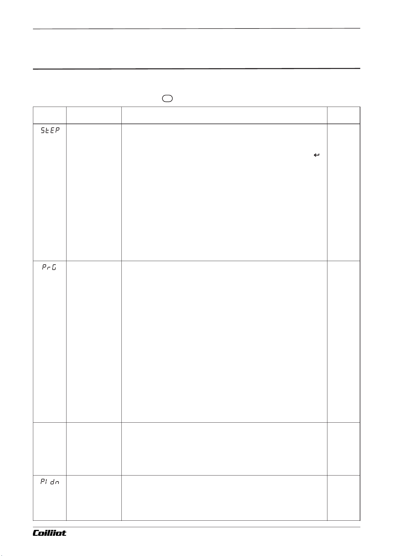
In the basic display state, press and hold key for 2 sec to enter the field parameters.
Code
Name
Description
Range
(StEP)
Current
Program
Segment
Number
(Applicable to
975 Only)
StEP displays the current program segment number and can also be used to force a
jump to a specific segment during program operation.
Forced Segment Jump:
While the program is running, you can force it to jump to any segment. For example, if
the current StEP=3 and you want to jump to segment 8, set StEP=8 and press the
key to confirm. The program will immediately jump to segment 8 and begin execution
from there.
Setting Range of StEP:
The StEP setting range is constrained by the parameters PrGd and PrG. When the
instrument stops running (StoP), it will automatically reset StEP to the starting
segment.
Example 1:
If PrGd = 8 and PrG = 2, the program is divided into 8 groups of curves, and the
instrument is currently executing the second group. In this case, the StEP setting
range is limited to segments 11–20. After the instrument stops running (StoP), it will
reset StEP to the starting segment of that group (segment 11).
Example 2:
If PrGd = 0 and PrG = 0, meaning the program is not divided into groups, then StEP
can be set from segment 0 to 80. After the instrument stops running (StoP), it
automatically resets StEP to the first segment (segment 1).
1~80
(Default
Value
1)
(PrG)
Curve group
number
(Applicable to
975 only)
PrG displays the current program group (curve group) number in
execution.
By using PrGd, you can divide the program into multiple groups (curve
groups) to meet various process requirements. This allows you to
easily and quickly call up different curve sets by adjusting the PrG
parameter.
PrG Setting Ranges:
- If PrGd=0, the program is not divided into groups. PrG cannot be set
and is fixed at 0.
- If PrGd=4, the program is divided into 4 groups, and PrG can be set
from 1 to 4.
- If PrGd=8, the program is divided into 8 groups, and PrG can be set
from 1 to 8.
When the program is divided into groups by PrGd, you can predefine
multiple curve sets. By adjusting PrG, you can quickly and conveniently
select the desired curve group to execute.
Example:
If PrGd=4 and PrG=2, the program is divided into 4 groups, and the
instrument is executing the second group of curves (segments
21–40). After the instrument stops running (StoP), it automatically
resets StEP to the starting segment of the second curve group
(segment 21).
0~8
(Default
Value
0)
random
Segment Set
Time and
Elapsed Run
Time
(Applicable to
975 Only)
The PV display shows the segment’s set time, while the SV display
shows the elapsed time.
For example, if the PV display reads 30.0 and the SV display reads
10.0, it means the currently running segment’s total set time is
30.0 units, and 10.0 units of that time have already elapsed.
(Pidn)
PID parameter
group number
(applicable only
to 975)
Displays the current PID parameter group number being used.
This parameter must be defined through program settings.
- 1: Use the first set of PID parameters
- 2: Use the second set of PID parameters
- 3: Use the third set of PID parameters
0~3
(Default
Value
1)
Page 18/44 pages in total
F
A FUZZY-915/975 9- i Technical Manual_Version number: EN-V 01
Custom field
parameters
You can use FP1–FP8 to select any parameter from the system or
control parameters for on-site operation, allowing up to eight on-
site parameters to be added.
(LoC)
Password lock
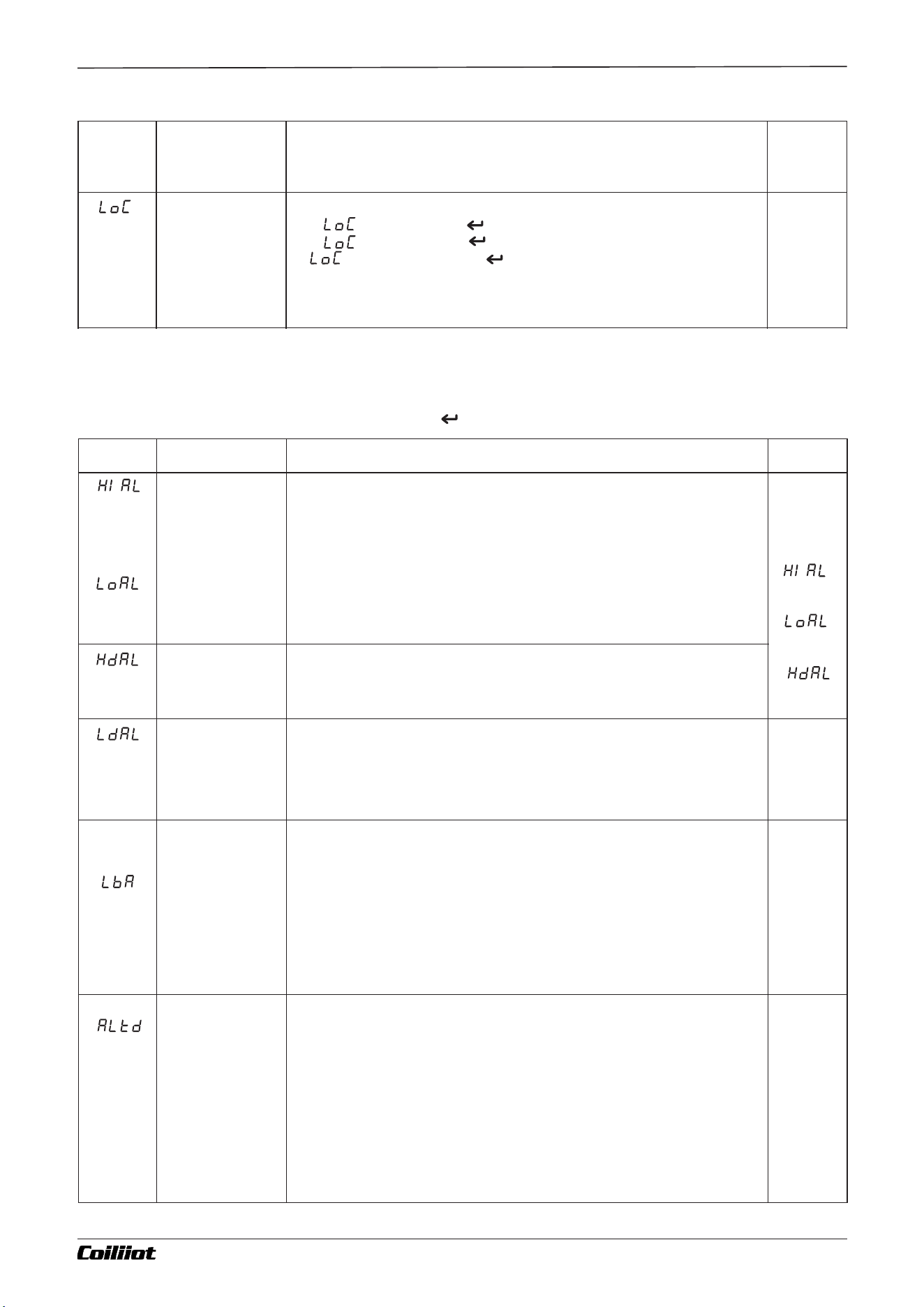
Parameter Setting Password Lock:
- Set = 800, then press to enter the following system parameters.
- Set = 801, then press to enter the following control parameters.
- If ≠ 800 or 801, pressing will return the instrument to the basic
display state.
0~9999
(Default
Value
0)
9.2 Function parameter
In the field parameters,set Loc=800,then press key to enter the function parameters.
Code
Name
Description
Range
(HIAL)
High limit alarm
When the measured value (PV) exceeds HIAL, the instrument triggers
a high-limit alarm. The alarm is cleared when PV falls below HIAL –
AHYS. If HIAL is set to its maximum value, this alarm function is
disabled.
Note: Each alarm can be freely assigned to the AL1, AL2, or AUX
output ports, or it can be left without any output action. For details,
refer to the description of the ALtd alarm output definition parameter.
-999~32
00
[-9990~
3200]
(HdAL)
Deviation high
alarm
When PV is less than LoAL, a low-limit alarm is triggered. The alarm is cleared when PV
rises above LoAL + AHYS. If LoAL is set to its minimum value, this alarm function is
disabled. Note: If needed, HIAL and LoAL can also be configured as deviation alarms (see
the SSCo parameter description for details).
(LdAL)
Deviation low
alarm
When the deviation (PV – SV) exceeds HdAL, a high-deviation
alarm is triggered. The alarm is cleared when the deviation falls
below HdAL – AHYS. If HdAL is set to its maximum value, this
alarm function is disabled.
-999~
3200
[-9990~
3200]
(Default
Value -999)
(LBA)
Control Loop
Open/Short-
Circuit Alarm
When the control output switches to otH or otL, the instrument begins monitoring the
measured value (PV) at intervals defined by LBA. It checks whether the PV changes by
more than 2°C within the specified LBA time. Based on this change, it determines whether
there is an abnormality in the control loop.
Note on LBA Timing: 1.The time unit for LBA is seconds. 2.Altd defines which alarm port
outputs the LBA alarm. 3.The LBA alarm cannot share the same output port with other
alarm types; doing so would cause overlapping alarms.
Conditions for LBA Alarm: 1. When orEV = onr (Reverse Action) and the instrument’s
control output continuously remains at otH: If, within the LBA set time, the PV increase is
less than 2°C, an LBA alarm is triggered.2. When orEV = ond (Direct Action) and the
instrument’s control output continuously remains at otH: If, within the LBA set time, the
PV decrease is less than 2°C, an LBA alarm is triggered.
0~9999
sec
(Default
Value 0)
(Altd)
Alarm output
definition
Note on ALtd Parameter Configuration:The ALtd parameter is represented as a four-digit
number. Each digit corresponds to a specific output port, allowing you to configure
different alarm types for each port:
- Thousands digit (the leftmost digit): AU2 port - Hundreds digit: Au1 port - Tens digit: Al2
port - Ones digit: Al1 port; Each digit can be set to a value from 0 to 9, which determines
the type of alarm assigned to that port:- 0: No alarm output - 1: HIAL (High-limit alarm) - 2:
LoAL (Low-limit alarm) - 3: dHAL (High-deviation alarm) - 4: dLAL (Low-deviation alarm) -
5: HIAL + LoAL outside-range alarm - 6: dHAL + dLAL outside-deviation alarm - 7: HIAL +
LoAL inside-range alarm - 8: dHAL + dLAL inside-deviation alarm - 9: LBA (Loop Break
Alarm) For example, if ALtd = 3091: - AU2 (thousands digit = 3) -> dHAL (High-deviation
alarm) - AU1 (hundreds digit = 0) -> No alarm - AL2 (tens digit = 9) -> LBA (Loop Break
Alarm) - AL1 (ones digit = 1) -> HIAL (High-limit alarm) This setting allows each port to
provide a specific, distinct type of alarm output as configured.
0~9999
(Default
Value 1)
(
Default
Value 3200)
(
Default
Value -999)
(
Ex-factory
Value 3200)
Page 19/44 pages in total
Chapter 9 Parameter table and functions
A FUZZY-915/975 9- i Technical Manual_Version number: EN-V 01
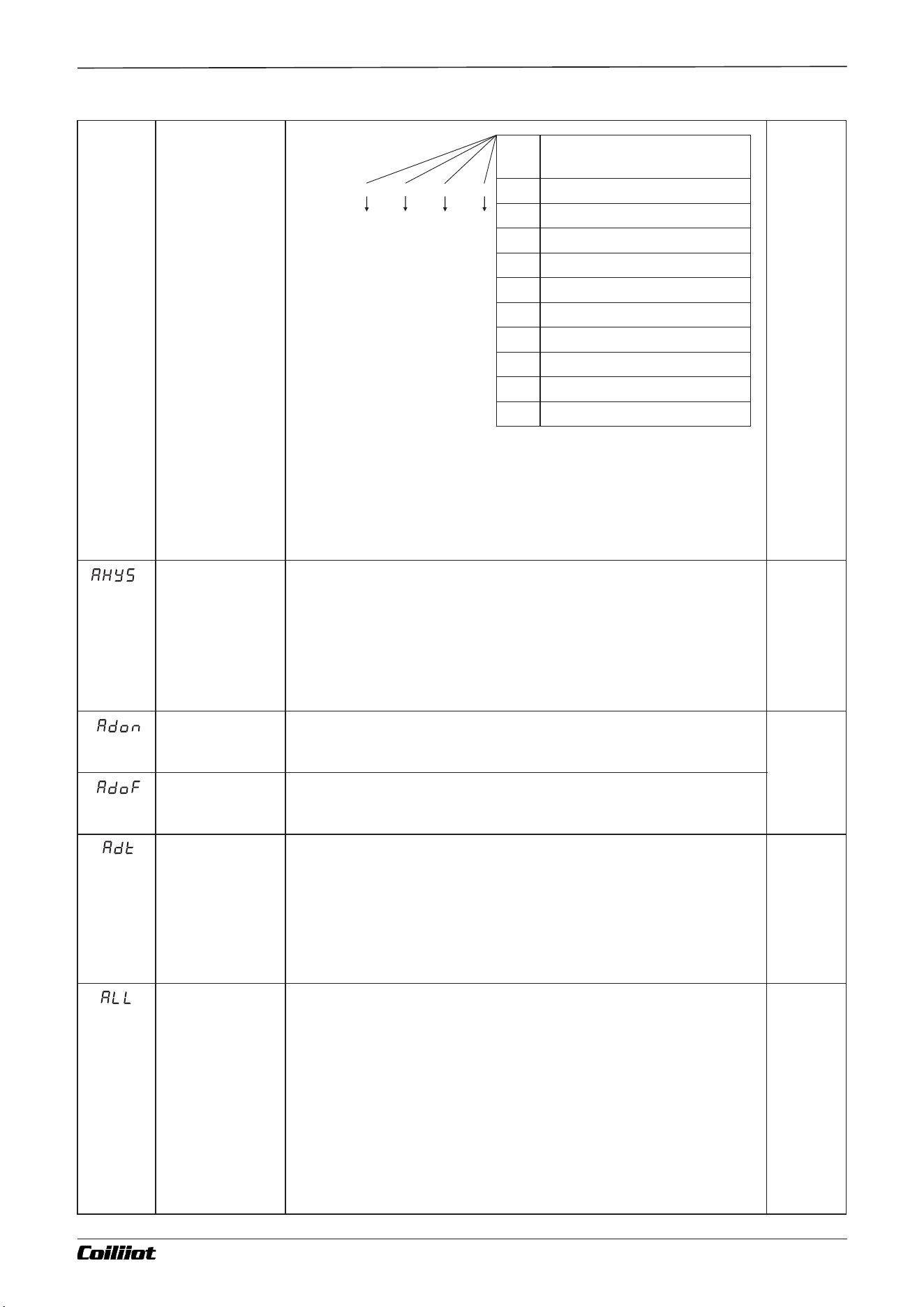
Example: If ALtd = 961, then:
- AL1 (ones digit = 1): Outputs HIAL (High-limit alarm)
- AL2 (tens digit = 6): Outputs dHAL + dLAL (High and Low
Deviation), achieving an outside-deviation alarm
- AU1 (hundreds digit = 9): Outputs LBA (Loop Break Alarm)
- AU2 (thousands digit = 0, since no digit was specified there): No
alarm output
(AHYS)
Alarm
hysteresis
Also known as alarm hysteresis or deadband, this parameter
helps prevent frequent switching of the alarm relay near the
threshold point. Once the alarm output turns ON, it will not turn
OFF until the measured value crosses the set threshold by the
hysteresis amount.
0~200.0
[0-2000]
(Default
Value
2)
(Adon)
Alarm ON delay
The Alarm ON Delay is a setting that determines the delay time (in seconds)
before the alarm is activated. If Adon=0, the alarm ON delay function is
disabled.
0~999
(Default
Value
0)
(AdoF)
Alarm OFF delay
The Alarm OFF Delay is a setting that determines the delay time (in seconds)
before the alarm is deactivated. If AdoF=0, the alarm OFF delay function is
disabled.
(Adt)
Alarm delay
definition
The alarm delay function can be configured as follows:
- 0: No alarm delay function.
- 1: Delay applies to AL1 alarm output.
- 2: Delay applies to AL2 alarm output.
- 3: Delay applies to AUX alarm output.
- 4: Reserved for future use.
- 5: Delay applies to both AL1 and AL2 alarm outputs.
- 6: Reserved for future use.
- 7: Delay applies to AL1, AL2, AU1, and AU2 alarm outputs.
0~7
(defalut
Value
0)
(ALL)
Definition of
alarm self lock
When the Alarm Latch Function is enabled, the alarm output remains latched
regardless of any changes in the measured value. The alarm will only reset if
the device is powered off and back on while the measured value no longer
meets the alarm condition.
The settings are as follows:
- 0: No alarm latch function.
- 1: Latch applies to AL1 alarm output.
- 2: Latch applies to AL2 alarm output.
- 3: Latch applies to AUX alarm output.
- 4: Reserved for future use.
- 5: Latch applies to both AL1 and AL2 alarm outputs.
- 6: Reserved for future use.
- 7: Latch applies to AL1, AL2, AU1, and AU2 alarm outputs.
0~7
(default
Value
0)
ALtd=□ □ □ □
AL2
AL1
AU1
Representative alarm
function parameters
value
0
No alarm output
HIAL(High limit alarm)
LoAL(Low limit alarm)
HdAL(High-deviation alarm)
LdAL(Low-deviation alarm)
HIAL+LoAL(outside-range alarm)
HdAL+LdAL(outside-deviation alarm)
HIAL+LoAL(inside-range alarm)
1
2
3
4
5
6
7
HdAL+LdAL(inside-deviation alarm)
LBA(Loop Break Alarm)
8
9
AU2
Page 20/44 pages in total
Chapter 9 Parameter table and functions
A FUZZY-915/975 9- i Technical Manual_Version number: EN-V 01
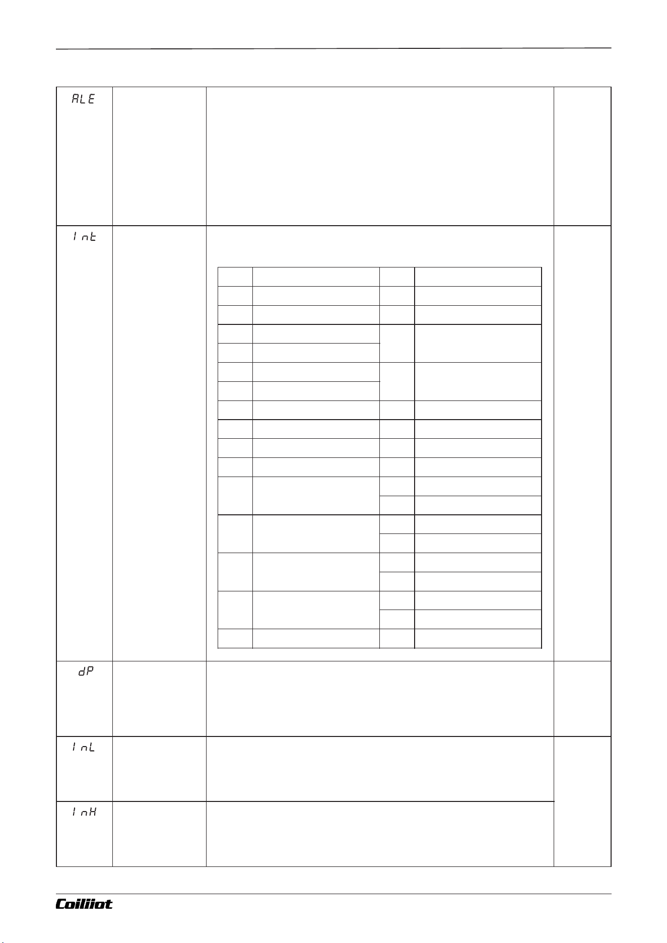
(ALE)
Definition of
First alarm
exemptions
When the Power-On Alarm Suppression function is enabled, the instrument does not
immediately trigger an alarm after powering on, even if the alarm conditions are met. The
alarm will only activate if the conditions are met again after first being cleared.
The settings are as follows:
- 0: No power-on alarm suppression function.
- 1: Suppression applies to HIAL alarm.
- 2: Suppression applies to LoAL alarm.
- 3: Suppression applies to HdAL alarm.
- 4: Suppression applies to LdAL alarm.
- 5: Suppression applies to both HIAL and LoAL alarms.
- 6: Suppression applies to both HdAL and LdAL alarms.
- 7: Suppression applies to HIAL, LoAL, HdAL, and LdAL alarms.
0~7
(Default
Value
0)
(Int)
Input
specification
Code
The AiFUZZY-915/975 offers a wide range of input specifications
that can be freely configured, as detailed below:
0~37
(Default
Value
0)
(dP)
Decimal Point
Position
Four display formats are available: 0, 0.0, 0.00, and 0.000.
Note: When using standard thermocouple or RTD (resistance
temperature detector) inputs, only 0 and 0.0 formats are
supported.
(Default
Value
0)
(InL)
Input Scale
Lower Limit
Defines the lower scale value for linear input signals. When the
instrument is used as a transmitter, it also defines the lower scale
value for the output signal.(CntL=Pvtr or Svtr) .
999~
3200
[-9990~
32000]
(Default
Value
300)
(InH)
Input Scale
HigherLimit
Defines the upper scale value for linear input signals. When the
instrument is used as a transmitter, it also defines the upper scale
value for the output signal.(CntL=Pvtr or Svtr) .
Int
Input spec
Int
Input spec
0
K(-50.0~+1300°C)
18
J(0~300.00)
1
S(-50~+1700℃)
20
Cu50
2
R(-50~+1700℃)
21
Pt100(-200.0~+ 600.0°C)
3
T(-200~+350℃)
4
E(0~800℃)
22
Pt100(-100~+300.00°C)
5
J(0~1000℃)
6
B(200~1800℃)
25
0~75mV
7
N(0~1300℃)
26
0 80Ω~
8
WRe3-WRe25
27
0 0Ω~40
9
WRe5-WRe26
28
0 20mV~
10
Special custom input
specification
29
0 100mV~
30
0 60mV~
12
F2 radiation type pyromter
31
0 500mV~
32
100~500mV
15
Spare
33
1 5V 4 20mA~ ( ~ )
34
0 5V 20mA~ (0~ )
16
Spare
35
0-10V
36
2-10V
17
K(0~300.00)
37
0-20V
Page 21/44 pages in total
Chapter 9 Parameter table and functions
A FUZZY-915/975 9- i Technical Manual_Version number: EN-V 01
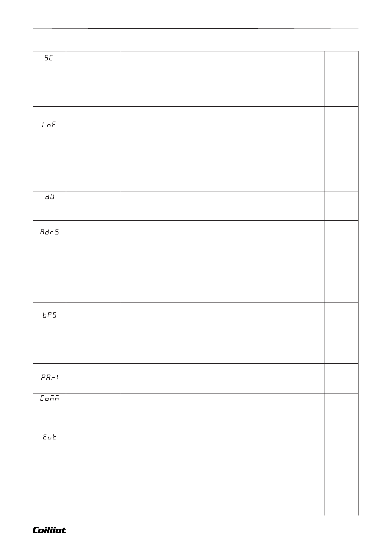
(SC)
Input Correction
This parameter applies an offset adjustment to the input signal to
compensate for errors in the sensor or the input signal itself.
The SC parameter is typically set to 0.Adjustment is not
recommended unless necessary, as incorrect settings can
introduce additional errors.
-199~
400
[-1990~
4000]
(Default
Value 0)
(InF)
PV input filter
The value of InF determines the ability to filter noise from the
input signal.
- When a large value is set, the measurement input stabilizes, but
the response speed slows down. Typically, it can be set between 1
and 3.
- If significant interference is present, gradually increasing the InF
value can help reduce momentary fluctuations in the measured
value, keeping them within 2 to 5 units.
- During metrological verification of the instrument, set InF to 0 or
1 to shorten the response time.
0~40
(Default
Value
0)
(dU)
Temperature
unit
°C: Celsius.
°F: Fahrenheit.
Thermocouples and RTDs only
(Default
Value
° C)
(AdrS)
Communication
address
If the instrument's COMM port is configured with an S-type RS485
communication interface module, it can be connected to a
computer in a multi-device setup. Through the computer, all
parameters of the instrument can be read and adjusted.
For computers without an RS485 interface, an RS232C/RS485
converter or a USB/RS485 converter can be used.
The AdrS parameter defines the communication address of the
instrument, with a valid range of 0 to 80.
- Each instrument on the same communication line must have a
unique AdrS value to ensure proper identification and distinction.
0~100
(Ex-
factory
Value
1)
(bPS)
Baud rate
The bPS parameter defines the communication baud rate, with a configurable range of
1200 to 19200 bit/s (1.2 to 19.2 Kbps).
If the instrument does not require communication functionality, the bPS parameter can be
configured to use the AUX port as a transmitter for the PV (Process Variable)
measurement value. This enables the instrument to provide one PID control output and
one transmission output.
The configurations are as follows:
- bPS = 3: The AUX port is set to transmit measurement values as a 0~20mA output.
- bPS = 4: The AUX port is set to transmit measurement values as a 4~20mA output.
0~19.2K
(Default
Value
9600)
(PArL)
Communication
parity
nonE:No verification. odd:Odd. EVEn: Even
(Default
Value
nonE)
(COMM)
Communication
protocol
FBUS: instrument communication protocol for FTBUS.
MBUS: instrument communication protocol for MODBUS.
(Default
Value
MBUS)
(Evt)
Event input type
When the MIO position is equipped with an I2 switch signal module, the Evt
parameter can be configured for the following functionalities:
- oFF: Disables the event input function.
- ruSt: Run/Stop Control
- When the MIO port is set as an I2 switch signal input:
- A short press of the switch signal starts the operation control (RUN).
- Holding the switch for more than 2 seconds stops the control (STOP).
- SP1.2: Setpoint Switching Control
- When fixed-point control is enabled (975 parameter PrSn=0):
- If the MIO switch signal is disconnected, the set value (SV) is SP1.
- If the MIO switch signal is connected, the set value (SV) switches to SP2.
(Default
Value
oFF)
Page 22/44 pages in total
Chapter 9 Parameter table and functions
A FUZZY-915/975 9- i Technical Manual_Version number: EN-V 01
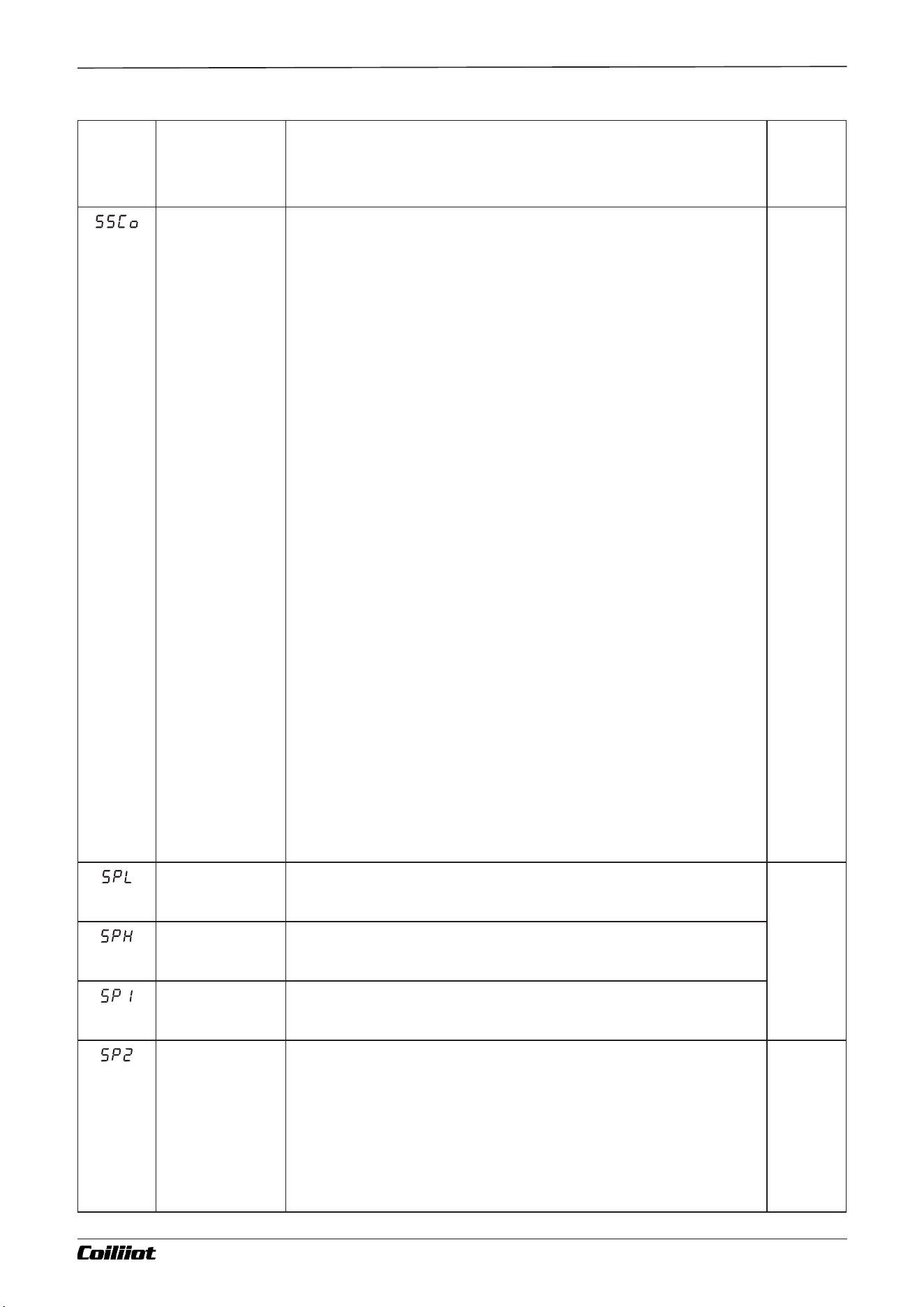
- 2PId: Dual PID Control
- For single-direction control (not dual heating/cooling control):
- If the MIO switch signal is disconnected, the system uses P, I, D, and CP parameters for PID regulation.
- If the MIO switch signal is connected, the system switches to using P2, I2, D2, and CP2 parameters for
PID regulation.
(SSCo)
Advanced
System Code
The SSCo parameter is used to select advanced functionalities by
calculating a value based on the formula:
SSCo=A×1+B×2 +C×4 +D×8+E×16+F×32+G×64+H×128
Configuration Options:
A
- A=0: HIAL and LoAL are configured as absolute high and low limit
alarms.
- A=1: HIAL and LoAL are changed to deviation high and low limit
alarms, allowing for four deviation alarms.
B
- B=0: HdAL and LdAL are configured as deviation high and low limit
alarms.
- B=1: HdAL and LdAL are changed to absolute high and low limit
alarms, providing two absolute high and two absolute low alarms.
C
- C=0: Alarm and hysteresis adjustment are configured as single-
sided hysteresis.
- C=1: Alarm and hysteresis adjustment are configured as double-
sided hysteresis.
D, E, F, G
- Reserved. Must be set to 0.
H
- H=0: Precision Control Mode
- The internal PID resolution is 10 times the displayed value (e.g., if
the temperature is displayed as 1°C, internal PID operates with 0.1°C
resolution).
- Maximum display value for linear input is 3200 units.
- H=1: Wide-Range Display Mode
- Use this mode when linear input values exceed 3200 units.
Example Calculation:
If the requirement is:
- HIAL as absolute high limit alarm,
- HdAL as absolute high limit alarm,
- Alarm hysteresis as double-sided hysteresis,
- No specific requirements for other options:
The calculation is:
SSCo=0x1+1x2+1x4 +0×8+0×16+0×32+0×64++0x128=6
Thus, the SSCo value is 6.
0~255
(Default
Value
0)
(SPL)
Min of SV
Minimum value that SV is allowed to be.
-999~32
00
[-9990~
32000]
(Default
Value
-
999~320
0)
(SPH)
Max of SV
Maximum value that SV is allowed to be.
(Sp1)
Set point 1
For the 915 or 975 model, when the parameter PrSn=0 or 1, and Evt=SP1.2 is set
for event input, it can be used to switch to Setpoint 1 (SP1). Under normal
conditions, the set value (SV) defaults to SP1.
(SP2)
Set point 2
For the 915 or 975 model, when the parameter PrSn=0 or 1, and
Evt=SP1.2 is set for event input, it can also be used as Setpoint 2
(SP2).
When the MIO port is configured as an I2 switch signal input and the
Evt=SP1.2 parameter is set, an external switch can be used to toggle
between SP1 and SP2:
- When the switch is disconnected, the set value (SV) is SP1.
- When the switch is connected, the set value (SV) switches to SP2.
-999~320
0
[-9990~
32000]
(Default
Value
0)
Page 23/44 pages in total
Chapter 9 Parameter table and functions
A FUZZY-915/975 9- i Technical Manual_Version number: EN-V 01
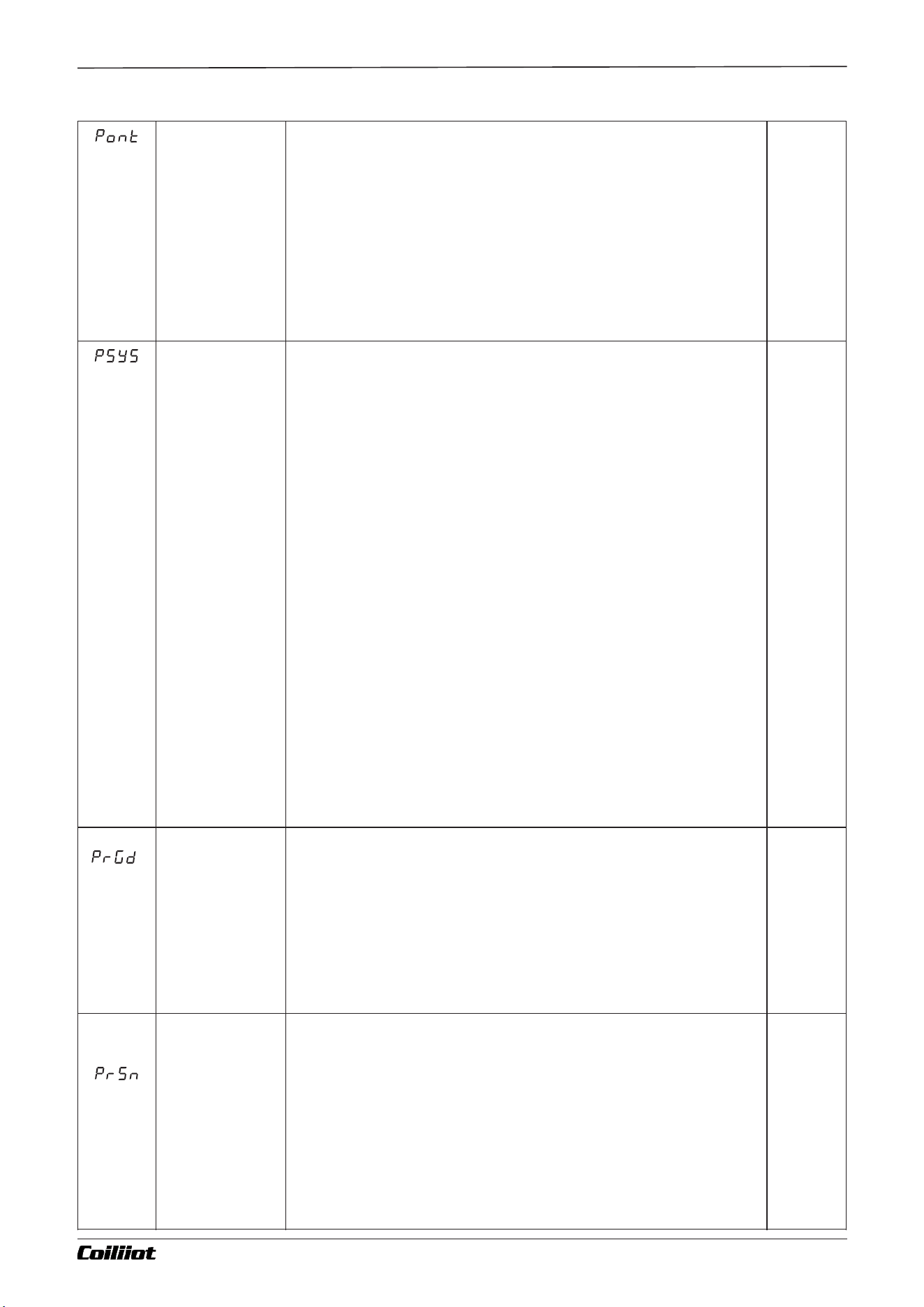
(Pont)
Power-On
Automatic
Operation Mode
(Applicable only
to the 975
model)
The power-on automatic operation mode determines the instrument's behavior after a power outage and
subsequent restoration. The options are:
- Cont:
- If the instrument was in a stopped state before the power outage, it remains stopped upon power
restoration.
- Otherwise, the instrument resumes execution from where it stopped.
- StoP:
- Regardless of the previous state, the instrument enters the stopped state upon power restoration.
- run1:
- If the instrument was in a stopped state before the power outage, it remains stopped.
- Otherwise, it restarts the program from the beginning upon power restoration.
- dASt:
- After power restoration, the program continues execution if no deviation alarm is present.
- If a deviation alarm occurs, the program stops.
- HoLd:
- If the instrument was running before the power outage, it enters a pause state upon power restoration.
- If the instrument was stopped before the power outage, it remains in the stopped state upon power
restoration.
(Default
Value
run1)
(PSyS)
Program
Running mode
(applicable only
to 975)
The PSYS parameter is used to configure program control functionalities by
calculating a value based on the following formula: PSYS = A×1 + B×2 + C×4 +
D×8 + E×16 + F×32
1. A (Ready Function): - A=0: The ready function (rdy) is disabled.
- A=1: The ready function is enabled.
2. B (Program Mode):
- B=0: Ramp Mode: - When a temperature difference exists during program
execution, the transition follows a ramp (linear). - Allows for different heating
modes or cooling execution. - B=1: Platform Mode (Constant Temperature
Mode): - Each program segment defines a setpoint and holding time. - The
transition rate between segments can be limited by the rAtE parameter. -
Transition to the next segment may be restricted by the rdy (ready function)
parameter. - Note: If the program's final segment does not end with a
termination command, the constant temperature mode is executed even if B=0,
and the program ends automatically when the time is up.
3. C (Time Unit): - C=0: Program time is in minutes. - C=1: Program time is in
hours.
4. D (Measurement Value Start): - D=0: Measurement value start function is
disabled. - D=1: Measurement value start function is enabled.
5. E (Display Window): - E=0: When used as a program setpoint generator, the
upper display window shows the measured value. - E=1: When used as a
program setpoint generator, the upper display window shows the program
segment number.
6. F (Run Behavior): - F=0: Standard Operation Mode: The program executes
normally when running.- F=1: If the RUN operation is triggered during program
execution, the program enters the pause (HoLd) state.
(Default
Value
0)
(PrGd)
Program
grouping
(applicable only
to 975)
The PrGd parameter is used to define the program grouping configuration:
- PrGd = 0: No forced grouping of the program.
- PrGd = 4: The program is divided into 4 groups, each with 20 segments. This
allows for up to 4 curves to be programmed:
- Curve 1: Program segments 1-20.
- Curve 2: Program segments 21-40.
- Curve 3: Program segments 41-60.
- Curve 4: Program segments 61-80.
- PrGd = 8: The program is divided into 8 groups...
0~8
(Default
Value
0)
(PrSn)
No. of Program
(applicable only
to 975)
When PrGd=0, the program does not use forced grouping. The PrSn parameter defines the
number of active program segments, with a range from 0 to 80. This allows unnecessary
program segments to be removed, making operation and program setup more convenient
for the end user.
- When PrSn=0, the 975 operates in constant temperature mode, fully compatible with the
operation of the 815 model.
- The rAte parameter can be used to limit the heating rate.
- When PrSn=1, the instrument operates in single-segment mode, requiring only one
setpoint value and one hold time, making it very simple to configure.
- When PrSn=2-50, the 975 operates in normal program control mode with the specified
number of segments (e.g., setting PrSn=10 means the instrument will have only 10
segments, and the other segments will not be displayed).
When PrGd=4 or PrGd=8, the program is forced into grouping, and the PrSn parameter is
fixed to 80 and cannot be modified.
0~8
(Default
Value
80)
Page 24/44 pages in total
Chapter 9 Parameter table and functions
A FUZZY-915/975 9- i Technical Manual_Version number: EN-V 01
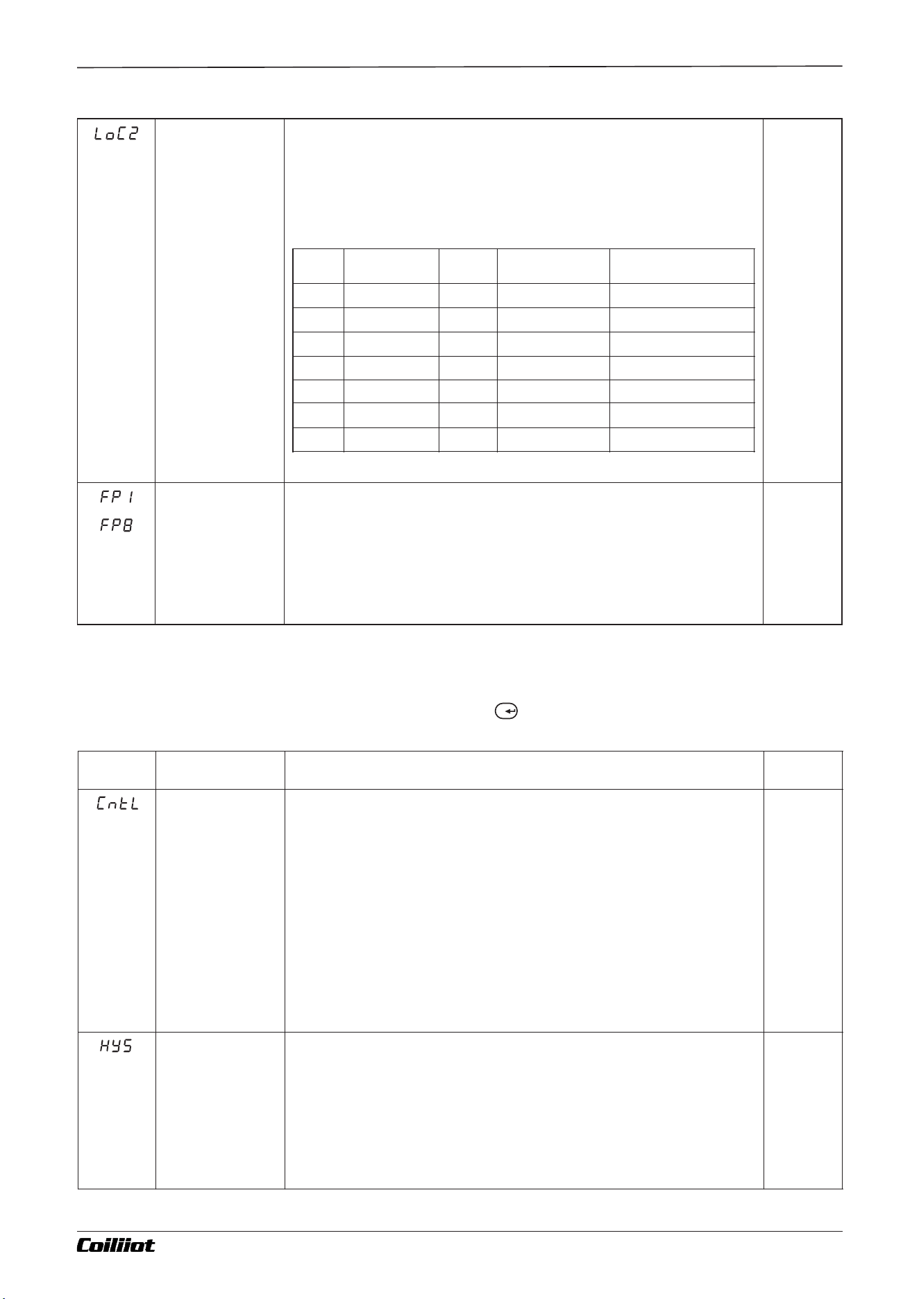
(LoC2)
Parameter Lock
Parameter was protected by LoC2 (Parameter LOCK) to prevent
setting error. The function was shown as below:
√ : allow to modify data or execute
: not allow to modify data or execute
Run, Stop, Hold. and Program Time & Temp.
Function just for 975 only
(Default
Value
oFF)
(FP1
~FP8)
Field parameter
definition
Through Fp1 to FP8, you can select any 8 parameters from the
system and control settings to be used as field parameters, which
are accessible by on-site operators. If there are fewer than 8 field
parameters or if some are not needed, their values can be set to
NONE. This allows flexibility in configuring which parameters are
available for on-site operation.
(Default
Value
nonE)
LOC
Field
parameters
SV
Program Step
Time & Temp
Shortcut keys for run,
stop, or hold
oFF
√
√
√
√
LCK1
√
√
√
LCK2
√
√
LCK3
√
LCK4
√
√
√
LCK5
√
√
LCK6
~
9.3 Control parameter
In the field parameters, set Loc=801,Then press the key to enter the control parameters.
Code
Name
Description
Range
(CntL)
Control mode
- onoF: Uses ON-OFF control (binary control), which is suitable for
applications with low control requirements.
- FPId: Uses the advanced PID + FUZZY artificial intelligence control
algorithm, which is recommended for more precise and dynamic
control applications.
- Pvtr: When the instrument is used as a measuring display instrument
or digital transmitter, the SV will display the temperature unit. In the
case of linear signal input, SV will not display, and the PV value can be
used directly as the output value. If the OUT port is equipped with a 4-
20mA module, the instrument can function as a transmitter.
- Svtr: The SV value is directly used as the output value. When the OUT
port is equipped with a 4-20mA module, the instrument can function
as a program setpoint generator.
(Default
Value
FPId)
(HYS)
Control
Hysteresis
The ON-OFF hysteresis is used to prevent frequent switching of the relay in ON-OFF control
applications.
- For reverse action (heating) control:
- When the PV (Process Variable) is greater than the SV (Setpoint), the relay is turned off.
- When the PV drops below SV - HYS (hysteresis value), the relay is turned back on.
- For direct action (cooling) control:
- When the PV is less than the SV, the relay is turned off.
- When the PV exceeds SV + HYS, the relay is turned back on.
This hysteresis function ensures more stable control by preventing the relay from
switching on and off too frequently due to small fluctuations in the process variable.
0~200.0
[0-2000]
(Default
Value
2)
Page 25/44 pages in total
Chapter 9 Parameter table and functions
F/
A FUZZY-915/975 9- i Technical Manual_Version number: EN-V 01
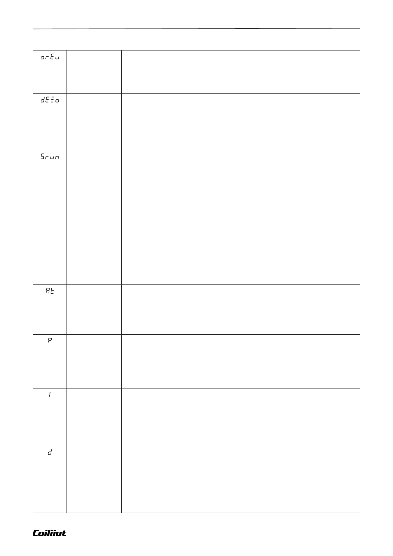
(orEv)
Acting control
(Control
direction)
onr: Reverse action control (heating control).When the input
increases, the output tends to decrease (e.g., heating control).ond:
Direct action control (cooling control).When the input increases, the
output tends to increase (e.g., cooling control).
(Default
Value
onr)
(dEZo)
dead zone
This function is only applicable in heating and cooling dual-channel bidirectional control
systems.
- The dead zone is centered around the setpoint.
- When the setpoint value is positive, it becomes the dead zone (non-action zone), where
no control action is taken.
- When the setpoint value is negative, it becomes the overshoot zone, where the system
may exceed the setpoint temporarily to improve control.
- The decimal point position is defined by the dP parameter.
-1999~
9999
(Default
Value
0)
(Srun)
Running Status
- run: The running control state allows the system to operate normally and
enables the execution of run or stop operations via the panel buttons.
- StoP: The stopped state where the system is not running, but you can still
start or stop the operation using the panel buttons.
- HoLd: The hold running control state.
- For the 915 or 975 models, if PrSn=0, this state is equivalent to the normal
running state but prevents the use of panel buttons for starting or stopping the
operation.
- For the 875 model with PrSn>0 (program control), the instrument maintains
control output but pauses the timing. In this state, the SV (setpoint value) is
displayed with a flashing "HoLd" on the second display. The running control or
stop can be performed through the panel buttons to exit the hold state.
Note: You cannot enter the hold state using only the panel operation. The hold
state can only be entered by directly modifying this parameter, through
programming during program execution, via host communication, or event
input.
(Default
Value
run)
(At)
Auto tuning
- oFF: The auto-tuning (At) function is disabled.
- on: The PID auto-tuning function is activated. After the auto-
tuning process is complete, it will automatically return to oFF.
- FoFF: The auto-tuning function is disabled, and it is forbidden to
start auto-tuning from the panel controls.
(Default
Value
oFF)
(P)
Proportional
band
(No.1 PID
parameter)
The proportional band for FPID control is expressed in the same
units as the PV value, rather than as a percentage of the range.
Generally, optimal P, I, D, and CP values can be obtained through
auto-tuning. Alternatively, they can be manually entered if the
correct values are already known.
1~3200
[32000]
(Default
Value
25)
(I)
Integral time
(No.1 PID
parameter)
The integral time for FPID control is measured in seconds. When
I=0, the integral action is disabled.
1~9999s
ec
(Default
Value
200)
(d)
Derivative Time
The derivative time for FPID control is measured in 0.1-second
units. When d=0, the derivative action is disabled.
0~3200
sec
(Default
factory
Value
50)
Page 26/44 pages in total
Chapter 9 Parameter table and functions
A FUZZY-915/975 9- i Technical Manual_Version number: EN-V 01
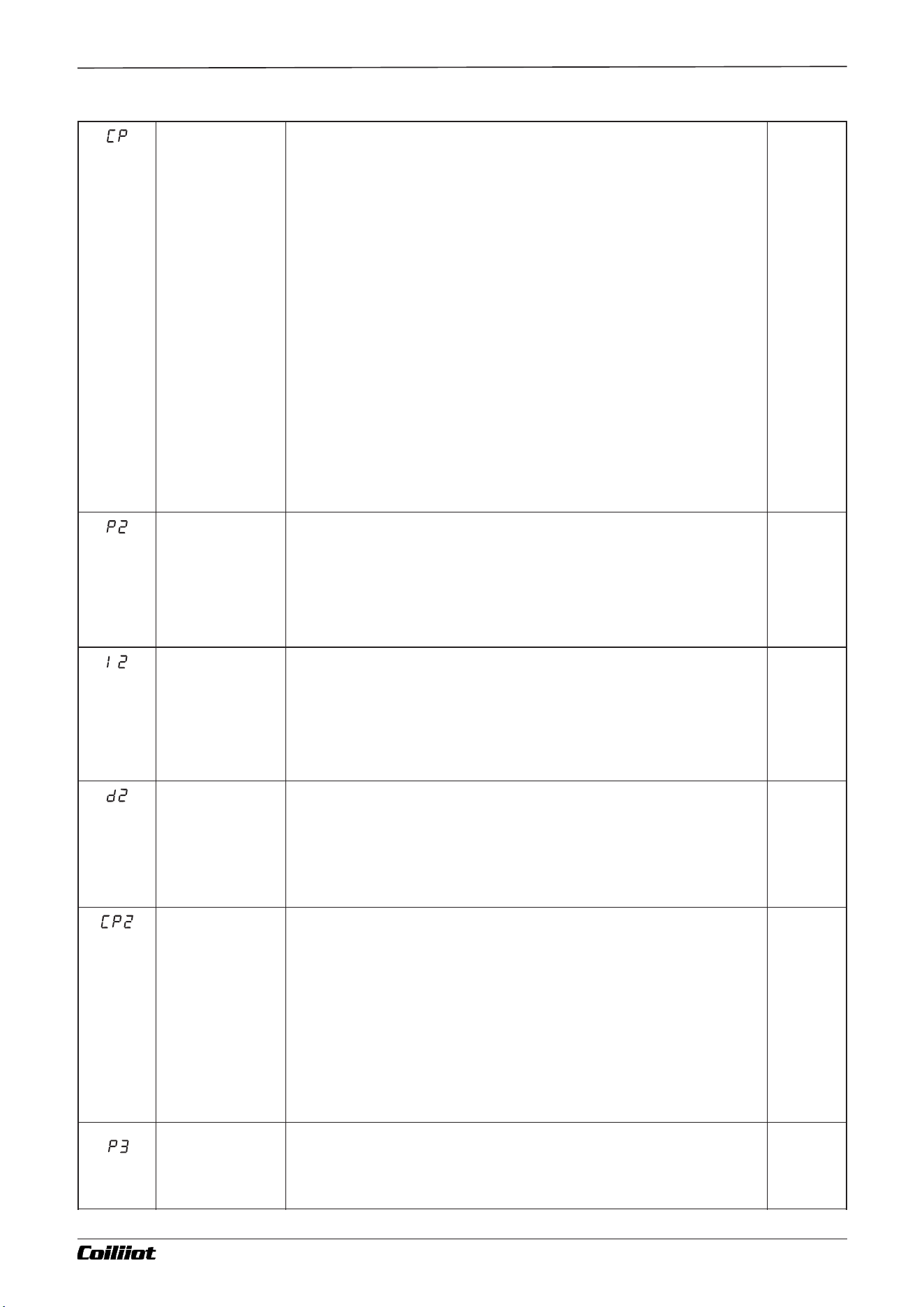
(CP)
Control cycle
(No.1 PID
parameter)
CP reflects the speed at which the instrument operator adjusts
the control. The size of the CP affects the control accuracy.
For SSR and SCR output control, a shorter control cycle is
preferred, typically between 0.5 to 3.0 seconds. For relay switch
outputs, a cycle time of 15 to 40 seconds is generally used.
When the output relay switches, the CP is limited to 3 seconds.
The self-tuning (AT) function will automatically adjust the CP to
the appropriate value, optimizing control accuracy and
prolonging the mechanical switch life.
When the control mode is set to CntL = onoF, the CP acts as the
output disconnect or power-on delay time.
0.2~
300.0
(Default
value 2,
OUT for
relay,
electrical
output,
when the
Default
value is:
15)
(P2)
Proportional
band 2
(No.2 PID
parameter)
In heating and cooling dual-output systems, the cooling output
proportional band for FPID control is defined in the same units as
the PV (Process Variable) value, rather than as a percentage of
the range.For the 975 model with 3 sets of PID parameters, the
proportional band for the second set of PID parameters is used
for controlling the cooling output.
1~3200
[32000]
(Default
Value
25)
(I2)
Integral Time 2
(No.2 PID
parameter)
In a heating and cooling dual-output system, the integral time for
the cooling output in FPID control is defined in seconds. When
I=0, the integral action is disabled.For the 975 model with 3 sets
of PID parameters, the integral time is applied to the second set of
PID parameters for controlling the cooling output.
1~9999s
ec
(Default
Value
200)
(d2)
Derivative time
2
(No.2 PID
parameter)
In a heating and cooling dual-output system, the derivative time for
the cooling output in FPID control is defined in 0.1-second units. When
d=0, the derivative action is disabled. For the 975 model with 3 sets of
PID parameters, the derivative time is applied to the second set of PID
parameters for controlling the cooling output.
0~3200
(Default
Value
50)
(CP2)
Control cycle 2
(No.2 PID
parameter)
In a heating and cooling dual-output system, the control cycle for the cooling
output in FPID control defines the time interval for adjusting the control action.
For the 975 model with 3 sets of PID parameters, this control cycle is applied to
the second set of PID parameters for controlling the cooling output.
- When using SSR (Solid-State Relay), SCR (Silicon-Controlled Rectifier), or
current output, the recommended control cycle is typically between 0.5 to 3.0
seconds.
- When the output is a relay switch (i.e., oUt or Aut is set to rELY), the actual
control period (CP) will be limited to 3 seconds or more.
- For relay-based control, the recommended control cycle is generally between
20 to 40 seconds to allow for proper switching and avoid excessive wear on the
relay.
0.2~
300.0
(Default
Value
2)
(P3)
Proportional
band 3
(No.3 PID
parameter)
Applicable to 975 only.
1~3200
[32000]
(Default
Value
25)
Page 27/44 pages in total
Chapter 9 Parameter table and functions
A FUZZY-915/975 9- i Technical Manual_Version number: EN-V 01
(I3)
Integral time 3
(No.3 PID
parameter)
Applicable to 975 only.
1~9999
sec
(Default
Value
200)
(d3)
Derivative time
3
(No.3 PID
parameter)
Applicable to 975 only.
0~3200
sec
(Default
Value
50)
(CP3)
Control cycle 3
(No.3 PID
parameter)
Applicable to 975 only.
0.2~
300.0
(Default
Value
2)
(oUt)
OUT primary
output type
- Ssr: Output for SSR (Solid-State Relay) drive voltage or SCR
(Silicon-Controlled Rectifier) zero-crossing trigger signal.
- rELy: Output as a relay contact switch.
- 0-20: 0~20mA linear current output (or 0-5V or 0-10V linear
voltage output).
- 4-20: 4~20mA linear current output (or 1-5V or 2-10V linear
voltage output).
- PHA: Single-phase SCR phase-shift output.
Note: Incorrect settings for the oUt parameter may result in
abnormal output operation.
(actory
default
values are
set
according
to the
purchased
model).
(Aut)
AUX auxiliary
output type (as
a cooling
output)
Ssr: Output for SSR (Solid-State Relay) drive voltage or SCR
(Silicon-Controlled Rectifier) zero-crossing trigger signal.
rELy: Output as a relay contact switch.
0-20: 0~20mA linear current output.
4-20: 4~20mA linear current output.
(actory
default
values are
set
according
to the
purchased
model).
(otL)
Min output
The Output Lower Limit (otL) setting functions as the minimum output value
for single-direction control when set between 0 to 100%.
When set between -1% and -110%, the instrument operates in a dual-output
system with heating/cooling control. This enables dual PID control, where:
- The main output (oUt) is used for heating.
- The auxiliary output (AUX) is used for cooling.
In this case:
- otL reflects the maximum cooling output limit.
- When otL = -100%, there is no restriction on the cooling output.
- When otL = -110%, the maximum output range can exceed 100% (e.g., for
current outputs like 4-20mA), which may be needed in special cases.
- For SSR or relay outputs, the maximum cooling output limit should not
exceed 100%.
Note: When changing otL from a positive to a negative value, or vice versa, a
power cycle (reboot) is required for the changes to take effect.
-110~
+110%
(Default
Value
0)
(otH)
Max output
The Output Upper Limit (otH) restricts the maximum value of the main output
(oUt). The range for this setting is 0 to 110%.
When using SSR (Solid-State Relay) or relay outputs, the maximum output limit
should not exceed 100%.
When using current output systems (e.g., 4-20mA), setting 110% allows the
maximum output to exceed the nominal range (e.g., beyond 20mA), which can
be useful in special cases.
Additionally, the otH setting must always be greater than otL (output lower
limit).
Page 28/44 pages in total
Chapter 9 Parameter table and functions
A FUZZY-915/975 9- i Technical Manual_Version number: EN-V 01
- otH can also be used in conjunction with otEr (output error limit) to implement
segmented power limiting.
- When the measured value (PV) is less than otEr, the maximum output value
(oUt) is limited by otH.
- When PV exceeds otEr, the output upper limit is corrected back to 100%.than
otL.
0~110%
(Default
Value
100)
(otEr)
Work range of
OPH
The otEr parameter enables segmented power limiting, allowing
the system to adjust the output limits based on the measured
value (PV).
- When PV is less than otEr, the main output (oUt) upper limit is set
to otH.
- When PV exceeds otEr, the output is no longer limited and is set
to 100%.
This feature is useful in situations where full power heating is not
allowed at low temperatures, such as in drying processes where
rapid heating needs to be avoided, or in applications like ovens
where moisture must be removed gradually.
For example:
- If the system is required to limit the heating power to 30% when
the temperature is below 150°C, you can set:
- otEr = 150.0°C (temperature threshold)
- otH = 30% (maximum output power when PV < 150°C)
In this case:
- When the temperature is below 150°C, the output power is
limited to 30%.
- When the temperature exceeds 150°C, the output power can go
up to 100%.
0-3200℃
/mi-
999~
3200℃
or Linear
unitn
(Default
Value
3200)
(rAtE)
Heating rate
limit
When the rAtE (rate of change) parameter is enabled, it defines a
temperature ramp-up rate during program startup. Specifically:
- If the measured value (PV) is lower than the setpoint (SV) at the
beginning of the program, the system will gradually increase the
temperature at the rate defined by rAtE until the setpoint is
reached.
- While in this ramping state, the PAR indicator light will flash to
indicate that the system is limiting the heating rate.
- In Slope Mode (rAtE = 0 or defined as a ramp), rAtE applies only to
the first program segment.
- In Platform Mode (defined by the program), rAtE is applied to all
program segments, controlling the ramp-up rate for each
segment.
0-3200℃
/min
(Default
Value
0)
Page 29/44 pages in total
Chapter 9 Parameter table and functions
A FUZZY-915/975 9- i Technical Manual_Version number: EN-V 01
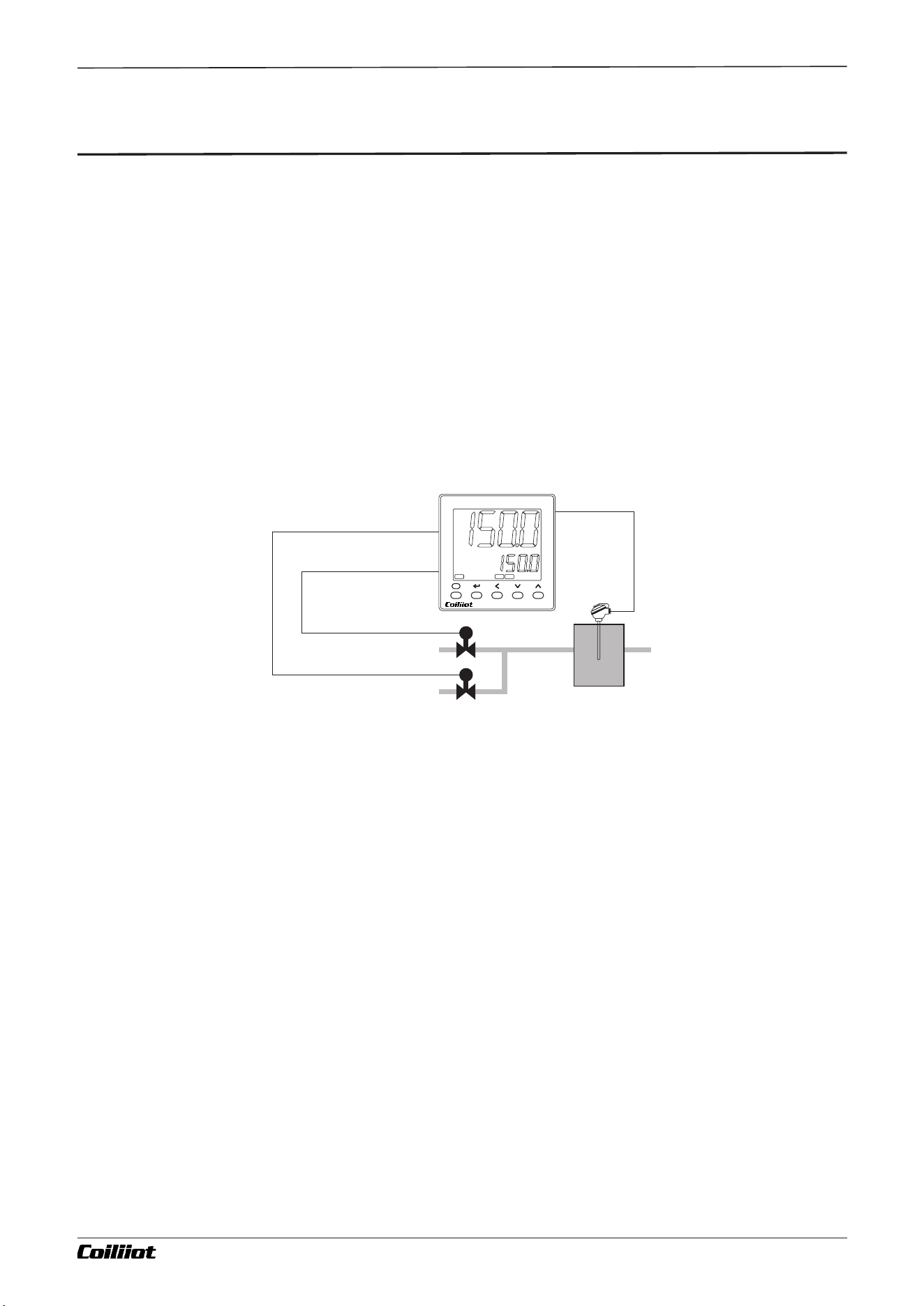
Chapter 10 Additional Functions
■10.Additional Functions
Page 30/44 pages in total
10.1 Phase Shift Trigger Output (SCR Voltage Regulation Output)
When the OUT is set to PHA, installing a K5/K6 module at the OUT port allows for a single-channel SCR
phase shift trigger output. This system can adjust the heating power continuously by controlling the
conduction angle of the SCR (either 2 unidirectional anti-parallel SCRs or 1 bidirectional SCR). It also applies
nonlinear power correction based on the characteristics of the sine wave, achieving highly ideal control
results. The trigger uses self-synchronization technology, allowing the instrument power supply and heater
power supply to be different.Additionally, you can install X or X5 modules at the OUT port to output linear
current or voltage signals, which can then trigger single-phase or three-phase SCR voltage regulation
modules (SCR).This module is currently only suitable for regions with a 50Hz power supply.
10.2 Heating/Cooling Dual PID Dual Control Output
When the setting for otL is a negative value (-1 to -110%), the instrument becomes a bidirectional
regulation system, providing heating/cooling dual PID dual output functionality. The main output oUt is used
for PID heating control output, while the auxiliary output AUX is used for PID cooling control output, as
shown in the diagram below:
10.3 Temperature Transmitter/Program Setpoint Generator
In addition to functioning as a conventional FPID or ON-OFF control system, the instrument can also
output the measured value (PV) or setpoint value (SV) directly from the OUT port. When the output is defined
as a current output, the AiFUZZY-915 can be used as a temperature transmitter, and the AiFUZZY-975 can
serve as a program setpoint generator. The 4-20mA current output accuracy is 0.3% of the corresponding
display value (FS). The relevant parameter settings are as follows:CntL=Pvtr for transmitting the PV value as
output.CntL=SVtr for transmitting the SV value as output.oUt, otL, and otH are used to select the output
range limits. Typically, a 4-20mA or 0-20mA output is chosen.
A FUZZY-915/975 9- i Technical Manual_Version number: EN-V 01
PV
SV
F
Ai FUZZY-900
ºFºC
OP1
AL1 AL2
Cold water
Hot water
OUT heating PID control
AUX cooling PID control
sensor input
energy-saving
equipment
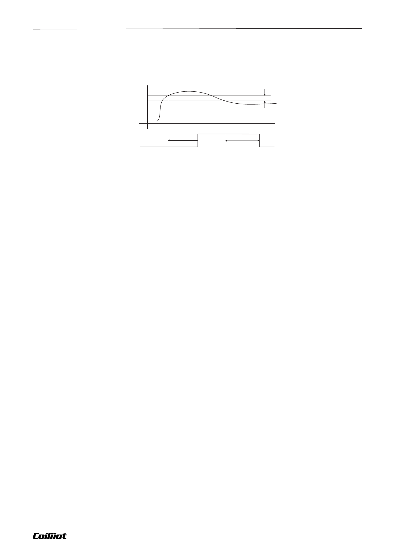
Chapter 10 Additional Functions
10.4 Alarm delay
Chart of alarm delay output:
The alarm ON interval is defined by the ON delay setting. If the condition is below the ON delay, the alarm
output will not turn ON. Similarly, the alarm OFF interval is defined by the OFF delay setting. If the condition is
below the OFF delay, the alarm output will not turn OFF. During the ON delay, if the alarm switches from ON ->
OFF -> ON, the measurement will reset and start counting from the time the alarm was last turned ON.
Similarly, during the OFF delay, if the alarm switches from OFF -> ON -> OFF, the measurement will reset and
start counting from the time the alarm was last turned OFF.
10.5 Alarm Latching Function
If the alarm latching function is enabled, the alarm output will remain ON regardless of temperature
changes when the alarm is triggered.
Alarm Unlocking Method: The alarm will be released after power is cut off (once the controller is powered
back on, if the measured value no longer meets the current alarm condition, the alarm will turn off).This
function is typically used for over-temperature protection. It can be employed to forcefully shut down the
main power supply in the event of over-temperature, and it will remain off until the operator resolves the
fault.
10.6 Power-On Alarm Suppression Function
When the instrument is powered on, unnecessary alarms may often be triggered. For example, in electric
furnace temperature control (heating control), right after power-on, the actual temperature is much lower
than the set point temperature. If the user has set a lower limit alarm or deviation lower limit alarm, the
alarm condition may immediately be met upon power-up, even though the control system may not
necessarily have any issues. On the other hand, in cooling control (direct action control), power-on may
trigger an upper limit alarm or deviation upper limit alarm. To address this, the AiFUZZY-900 series
instruments offer a power-on alarm suppression feature. When the orEV parameter is set to onr or ond, the
instrument will not immediately trigger the alarm, even if the corresponding alarm conditions are met at
power-on. The alarm will only be activated after the condition is cleared, and if the alarm conditions are met
again, the alarm will be triggered.
10.7 LBA Control loop break off / shorted Alarm
When the control output reaches otH or otL, the LBA (Loop Break Alarm) monitors changes in the PV
(Process Variable) value at each interval, based on the set LBA time. The amount of change is used to
determine whether there is an abnormality in the control circuit. The time unit for LBA is in seconds, and it
triggers the AL1 alarm.
The alarm conditions are as follows:
When orEV is set to onr (Reverse action):If the instrument’s control output remains at otH and the increase in
the measured value (PV) within the LBA set time is less than the threshold for LBA judgment (e.g., 2°C), the
alarm is triggered.
When orEV is set to ond (Positive action):If the instrument’s control output remains at otH and the measured
value (PV) decreases by less than the LBA judgment range (e.g., 2°C), the alarm is triggered.
Alarm hysteresis
OFF
delayed
Set time
Alarm status
Alarm setting
PV
ON delayed
Set time
Page 31/44 pages in total A FUZZY-915/975 9- i Technical Manual_Version number: EN-V 01
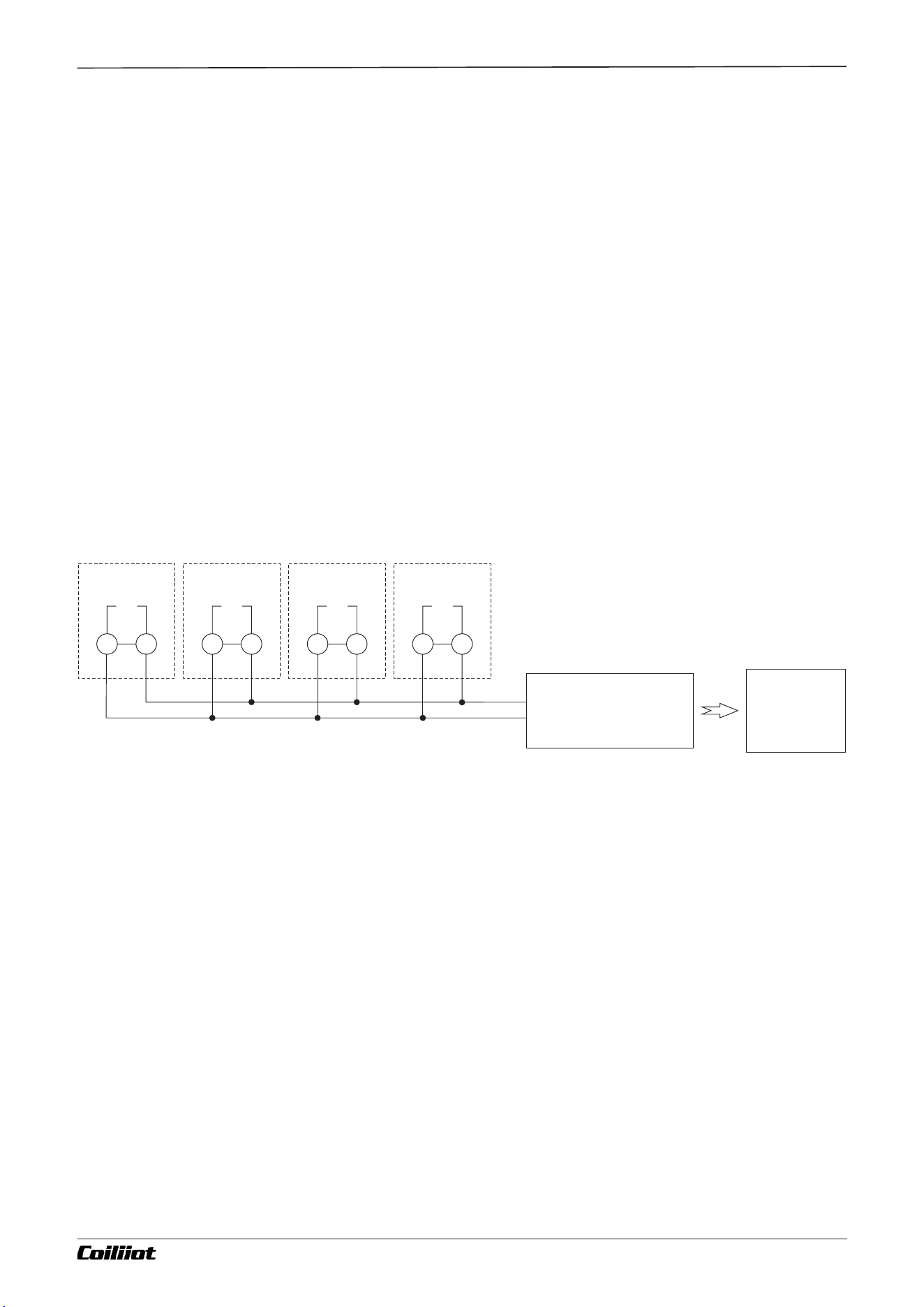
Chapter 10 Additional Functions
10.8 Fine Control
Fine control refers to a PID calculation resolution that is 10 times higher than the display resolution. For
example, while the instrument may display a temperature signal with a resolution of 1°C, the internal PID
computation and control still operate at a 0.1°C resolution. This allows for a control precision much higher
than the display resolution. In previous versions of the AiFUZZY-900 series, fine control mode was only
applied to the temperature signal. In the new version, for linear inputs, as long as the displayed value range
is below 3000 characters (most industrial applications do not exceed 3000 characters), fine control mode is
enabled by default to achieve higher control precision and more stable output. When a display value range
exceeds 3000 characters, the setting SSCo.H = 1 can be used to disable fine control mode.
10.9 Communication function
If the instrument’s COMM port is configured with an S-type RS485 communication interface module, it
can be connected to a computer for multi-device communication. Through the computer, various operations
and functions of the instrument can be controlled. For computers without an RS485 interface, an
RS232C/RS485 converter or a USB/RS485 converter can be added. Each communication port can directly
connect 1 to 60 instruments. With an RS485 repeater, up to 80 instruments can be connected. A single
computer can support multiple communication ports. Note that each instrument should be assigned a
unique address. When there are many instruments, two or more computers can be used, and these
computers can form a local network.
RS232C Communication
If the instrument’s COMM port is configured with an S2-type RS232C communication interface module, it
can only support one-to-one communication, as RS232C communication is not capable of multi-device
communication.
1# AiFUZZY-900 2# AiFUZZY-900 3# AiFUZZY-900 4# AiFUZZY-900
COMM COMM COMM COMM
A BA BA BA B
RS485 plug
or
RS485/RS232C converter
or
RS485/USB converter
Host
Computer
Page 32/44 pages in total A FUZZY-915/975 9- i Technical Manual_Version number: EN-V 01
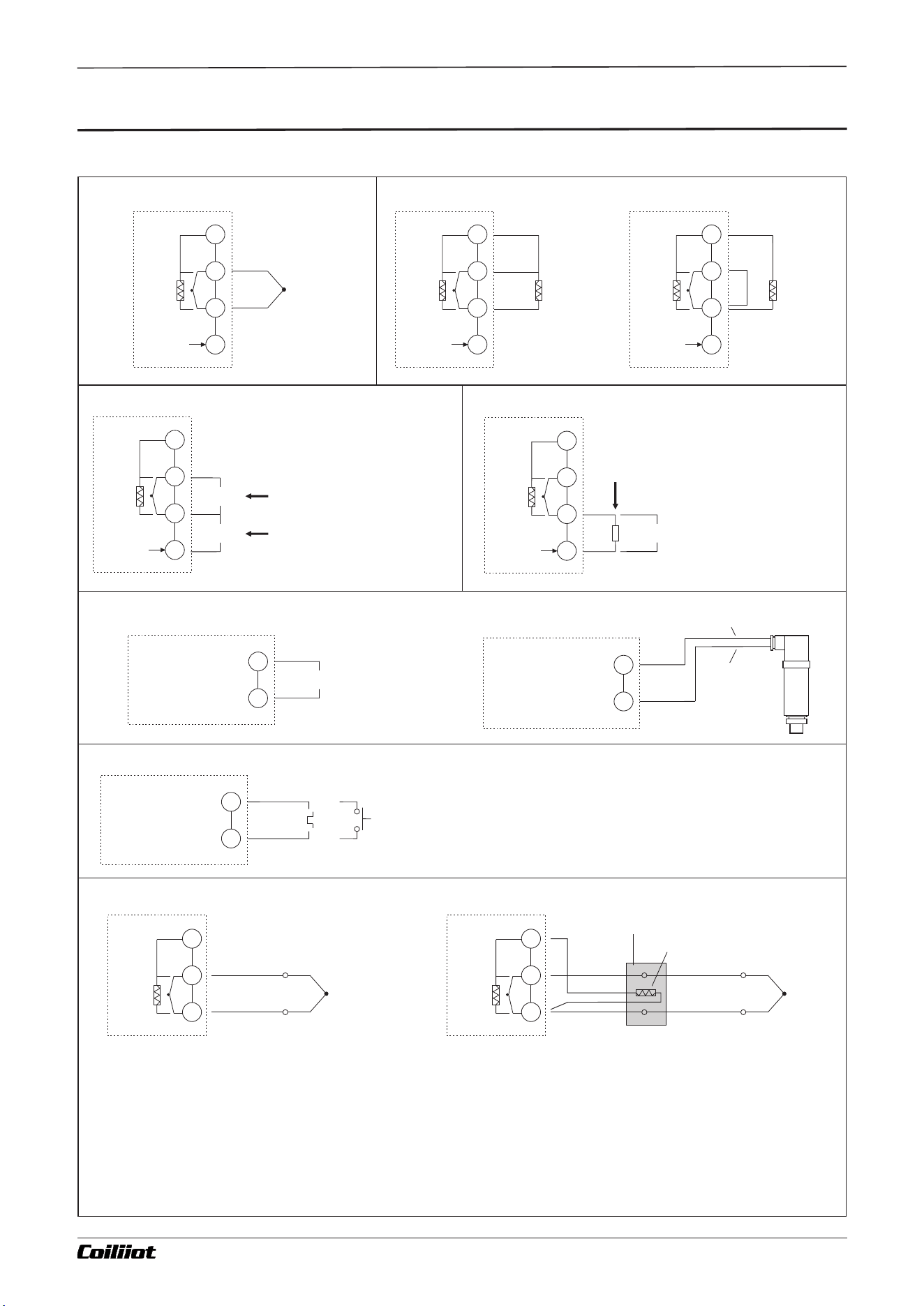
Chapter 11 Partial application wiring methods
MIO port input linear current
4-20mA/0-20mA
+
-
MIO
MIO port to
install
I3 module
+
-
MIO port to
install
I4 module
4-20mA
MIO
24V
Transmitter
4-20mA output port
Transmitter
24V power
port(+)
Two line transmitter
MIO port event input
MIO port to
install
I2 module
MIO
+
-
-
+
3-24V Pulse signalr
Contact signal
If the I2 module is installed on the MIO port, an external switch can be
connected to perform control functions. When the parameter Et=ruSt is
set, pressing the button once will execute the "run" operation. If the button
is pressed and held for more than 2 seconds, the "stop" operation will be
executed.For AiFUZZY-915 (or AiFUZZY-975) instruments with the
parameter PrSn=0 and EVt=SP1.2, this can be used to switch between two
different setpoints, SP1 and SP2.
Choosing thermocouple cold junction compensation mode based on wire connection
B
B
A
Pt
+
-
B
B
A
Pt
+
-
TC
Input
TC
Input
(1)Internal Automatic Compensation Mode
(The compensation wire should be directly connected to
the terminal block.)
(2)External Copper Resistance Automatic Compensation Mode
(The thermocouple cold junction terminal box should be kept
away from heat sources.)
When using a thermocouple as an input signal, according to the principle of thermocouple temperature measurement, it is
necessary to compensate for the temperature at the thermocouple's cold junction. The AiFUZZY-900 instrument can
automatically compensate for the cold junction temperature based on the temperature near the terminal block at the rear of
the instrument. However, due to factors such as measurement element errors, heat generated by the instrument itself, and
nearby heat sources, the automatic compensation method may result in a significant deviation, which in the worst case can
Cu50
Junction Box
Page 33/44 pages in total
11.1 The wiring method of the input signal
Thermocouple Input RTDs Input
Three-wire
RTD
B
B
A
Pt
0-5V
1-5V
+
+
-
TC
Input
RTD
Input
B
B
A
Pt
0-5V
1-5V
+
+
-
B
B
A
Pt
0-5V
1-5V
+
+
-
Two-wire
RTD
RTD
Input
short
circuit
Analog linear voltage input Analog linear current input
B
B
A
Pt
0-5V
1-5V
+
+
-
0-1V
0-5V
+
+
-
B
B
A
Pt
0-5V
1-5V
+
+
-
Voltage Input below1V,
Such as 0-1V, 0-20mV, etc.
Voltage Input Above 1V
Such as 0-5V, 1-5V, etc.
4-20mA Linear Current Input, an external
250-ohm resistor can be connected to
convert the 4-20mA current signal into a 1-5V
voltage signal.
250Ω
4-20mA/0-20mA
-
+
11.Partial application wiring methods
A FUZZY-915/975 9- i Technical Manual_Version number: EN-V 01
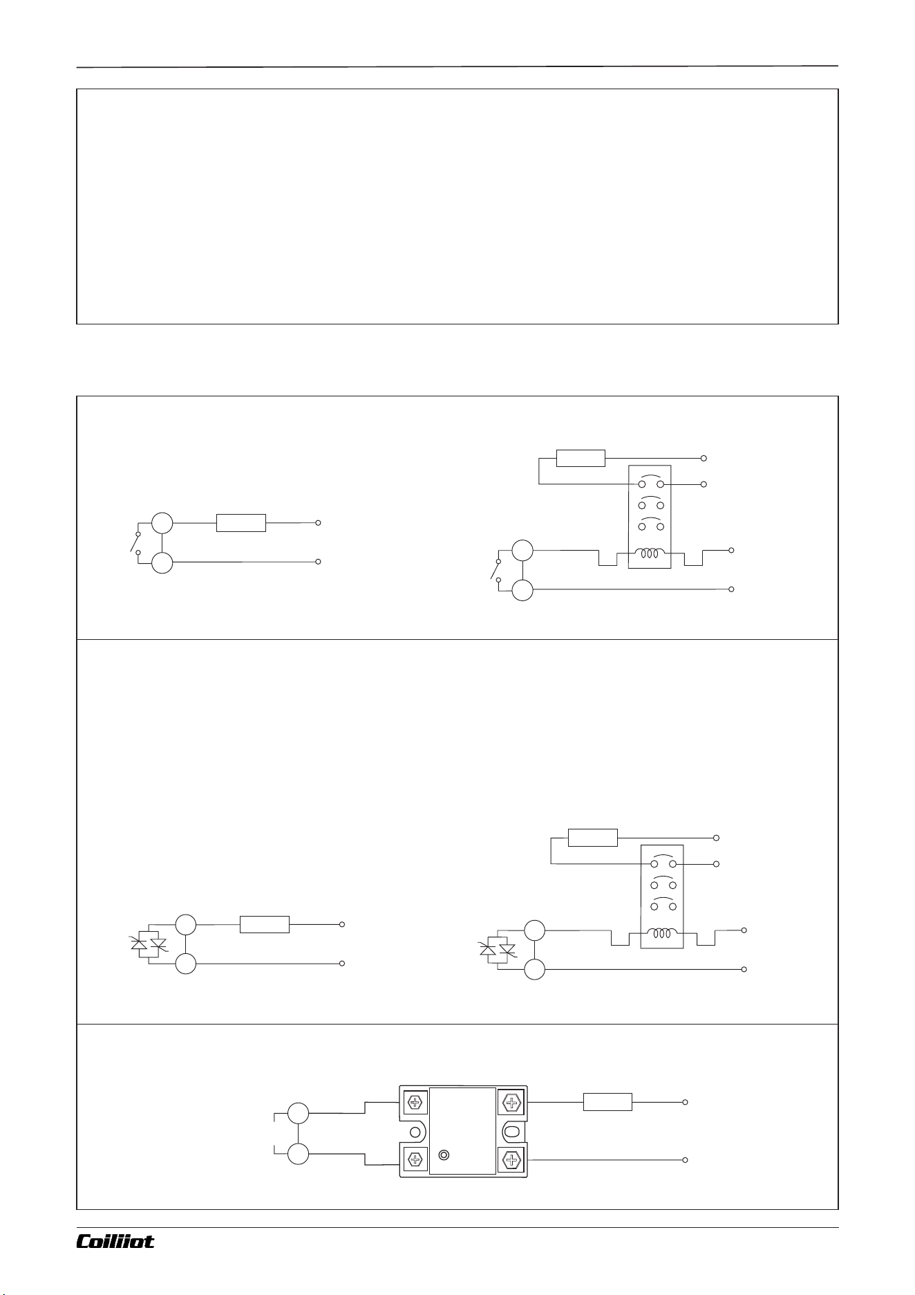
Silicon-Controlled Rectifier (SCR) Solid-State Switch Output (Built-in SSR Output)
(W Module Installed at OUT Port)
This new type of solid-state switch module functions like a built-in SSR output and can replace relay contact switches.
Compared to relay contact output modules, the W module offers a longer service life and lower interference. It
significantly reduces equipment interference from sparks and greatly improves system stability and reliability. It can
directly control resistive loads under 1A/240V (e.g., directly controlling a heating element up to 250W). For loads above
1A, it can control larger currents through an AC contactor.The driving element of the solid-state switch is a silicon-
controlled rectifier (SCR), so it is only suitable for controlling loads in the 100-240VAC range.
100~240V
Main power
Drive contactor control load
Max. 1A
Resistive load
Load
100~240V
Main power
Direct control load
Contactor
100~240V
Main power
Load
12V SSR drive voltage output(OUT port installed Q module)
100~240V
Main power
Load
1- OUTPUT- 2
SSR
INPUT
4-3-2VDC+3
Page 34/44 pages in total
OP1
OP1
+
-
OP1(SSR drive
voltage output
exceed 2°C.Therefore, for applications requiring high temperature measurement accuracy, an external junction box can
be used. In this box, a Cu50 copper resistance (to be purchased separately) and the thermocouple cold junction should
be placed together, away from heat sources. This approach ensures that the measurement inconsistency caused by
compensation is reduced to less than 0.3°C.
11.2 Main control output wiring method
Relay output (OUT port installs R module)
100~240V
Main power
Contactor
100~240V
Main power
Drive contactor control load
Load
Max. 3A
Resistive load
Load
100~240V
Main power
Direct control load
OP1
OP1
Chapter 11 Partial application wiring methods
A FUZZY-915/975 9- i Technical Manual_Version number: EN-V 01
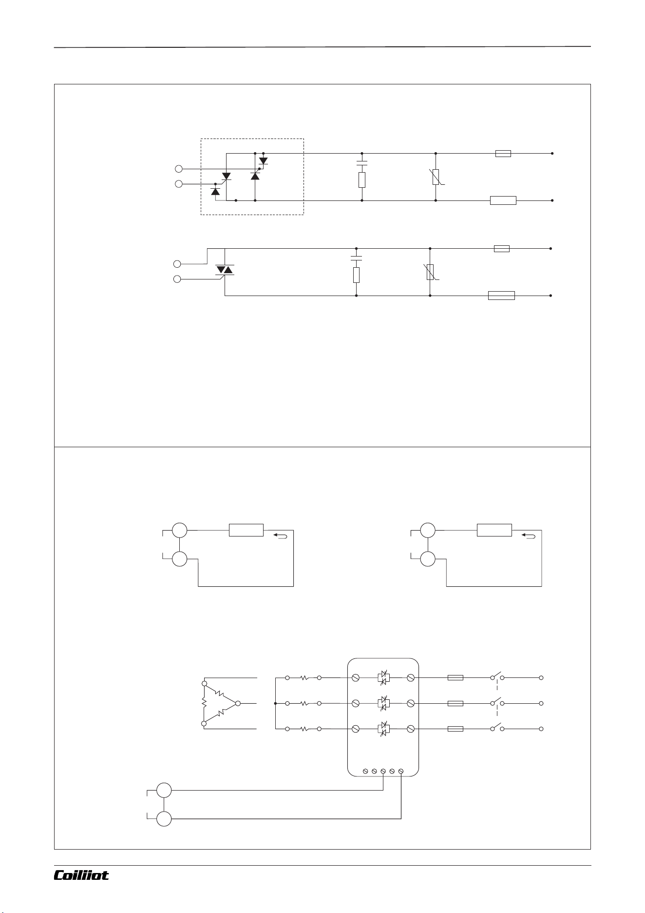
Linear Current and Voltage Output (X, X5, X8 Modules Installed at OUT Port)
Can Drive: SCR power regulators, SCR phase-shift trigger modules, PLCs, inverters, transmitters, valve actuators,
and other devices.
Minimum Load 10KΩ
0-5V,1-5V
0-10V,2-10V
Linear Voltage
Load
- +
Minimum Load 500KΩ
Load
0-20mA
4-20mA
Linear Current
- +
The following diagram illustrates the use of a 4-20mA output to trigger an SCR voltage regulation module or SCR
power regulator to control a three-phase heater, achieving power adjustment output:
Three
phase
power
This figure takes a three-
phase load as an example.
Circuit
breaker
Fast fuse
Three-phase
Y type
Heater load
Three-phase
triangle
Heater load
com
0-5V
4-20mA
R
S T
WVU
Page 35/44 pages in total
+
-
OP1(4-20mA
output)
OP1(4-20mA
output)
OP1(4-20mA
output)
+
-
+
-
Silicon-Controlled Rectifier (SCR) Trigger Output (K1, K5, K6 Modules Installed at OUT Port)
Varistor
BX
Capacitor Resistor
Absorber Circuit
SCR trigger output
SCR trigger output
G1
G2
IN4001
IN4001
SCR X2
5-500A
SCR Power Module
ZNR V
Fast fuse
100~240VAC
Load
Capacitor Resistor
Absorber Circuit
Varistor
BX
Fast fuse
100~240VAC
Load
ZNR V
TRIAC
5-500A
G1
G2
Note 1: Select a varistor based on the load voltage and current size to protect the SCR. If the load is inductive or phase
-shift triggering is used, an RC snubber circuit must be added.
Note 2: It is recommended to use an SCR power module, which contains two unidirectional SCRs inside, as shown in
the dashed part of the diagram.
Note 3: When using the K5 phase-shift trigger output module, the AC power supply
range is reduced to 200-240VAC. When using the K6 phase-shift trigger output module, the AC power supply range is
reduced to 340-415VAC, and the power frequency must be 50Hz.
Note 4: When using a three-phase, three-wire electric furnace with time-proportional zero-crossing trigger control, only
two bidirectional SCRs are needed for reliable control.
Chapter 11 Partial application wiring methods
A FUZZY-915/975 9- i Technical Manual_Version number: EN-V 01

Chapter 12 Input Error
■12.Input Error
When the display window alternates between SV and the "orAL" characters, it indicates an input signal error
or out-of-range measurement. Please check whether the Int parameter setting matches the type of input
sensor signal being used. If they match, verify that the input sensor wiring is correct. If the wiring is correct,
check if there is an issue with the sensor itself, and try replacing it with another sensor.
Page 36/44 pages in total A FUZZY-915/975 9- i Technical Manual_Version number: EN-V 01

Chapter 13 AiFUZZY-975 programming control
13.AiFUZZY-975 Programming Instructions
The AiFUZZY-975 program-controlled instrument is designed for applications that require automatic
adjustments of setpoints based on specific time schedules. It features an 80-step programming sequence,
allowing users to set arbitrary rates for increasing or decreasing setpoints. The instrument includes programmable
and operable commands such as jump, run, pause, and stop, and it permits modifications to the program during
operation. Additionally, it offers power failure handling modes, measurement-based start functions, and
preparation features, making program execution more efficient and comprehensive.
13.1 Functions and Concepts
- Program Segment: Segment numbers range from 1 to 80. The current segment (*StEP*) indicates the segment
currently being executed.
- Set Time: Refers to the total running time set for a program segment, measured in minutes or hours, with valid
values ranging from 1 to 999.9.
- Run Time: Indicates the elapsed time for the current segment. When the run time reaches the set segment time, the
program automatically proceeds to the next segment.
- Jump: Program segments can be programmed to automatically jump to any segment, enabling loop control. Jumps
can also be executed by modifying the *StEP* value.
- Run/Hold:
- Run: When the program is in the running state, the timer counts, and the setpoint changes according to the
prearranged program curve.
- Hold (Pause): While holding the run state (pausing), the timer stops, and the setpoint remains unchanged. The
hold operation can be incorporated within a program segment.
- Stop: Executing the stop operation will halt the program. At this point, the run time is reset to 0, timing stops, and
control outputs cease. If a run operation is executed while in the stopped state, the instrument will start running the
program from the segment number set in *StEP*. An automatic stop function can be programmed within a segment,
simultaneously setting the *StEP* value. Users can also manually execute the stop operation at any time (after
which *StEP* is set to 1, though it can be modified by the user). If the program segment number has reached the last
segment defined in the *PrSn* parameter, the program will automatically stop.
- Power Failure/Startup Events: Refers to the instrument being powered on or experiencing an unexpected power
outage during operation. By setting the *Pont* parameter, various handling schemes can be selected.
- Prepare (rdy) Function:
- Used when starting the run program or after an unexpected power failure/startup when the program needs to
continue running. If the measured value differs from the setpoint (if the measurement start function is allowed, the
system first handles it using the measurement start function; if effective, the prepare function is not needed. If the
conditions for the measurement start function are not met, the prepare function handles it) and the difference
exceeds the deviation alarm value (*HdAL* and *LdAL*), the instrument does not immediately trigger a positive (or
negative) deviation alarm. Instead, it first adjusts the measured value so that the error is less than the deviation
alarm value. At this point, the program timer is paused, and no deviation alarm signal is output until the positive or
negative deviation meets the requirements, after which the program restarts. The prepare function is also useful for
setting segments with unpredictable heating/cooling times. The prepare function can be enabled or disabled in the
*PSYS* parameter. This function ensures the integrity of the entire program curve but may increase the run time due
to the preparation period. Both the prepare function and the measurement start function are used to address
uncertainties caused by discrepancies between the measured value and the setpoint at program start, achieving
efficient, complete, and user-compliant program execution results.
- Measurement Start Function:
- When starting the run program or after an unexpected power failure/startup while needing to continue running the
program, the instrument's actual measured value often differs from the program-calculated setpoint, and this
discrepancy is sometimes unexpected and undesirable for the user.
- Example: Consider a heating segment program where the instrument is set to increase the temperature from 25°C
to 625°C over 600 minutes, with a heating rate of 1°C per minute. If the program starts at the beginning of this
segment and the measured temperature is exactly 25°C, the program can execute smoothly as planned. However, if
the system temperature hasn't yet cooled down upon startup, and the measured temperature is 100°C, the program
may not execute as smoothly as intended. The measurement start function allows the instrument to automatically
adjust the run time to align the two values. In the above example, if the measured temperature at program start is
100°C, the instrument automatically sets the run time to 75 minutes, allowing the program to start running directly
from the 100°C position.
Page 37/44 pages in total A FUZZY-915/975 9- i Technical Manual_Version number: EN-V 01
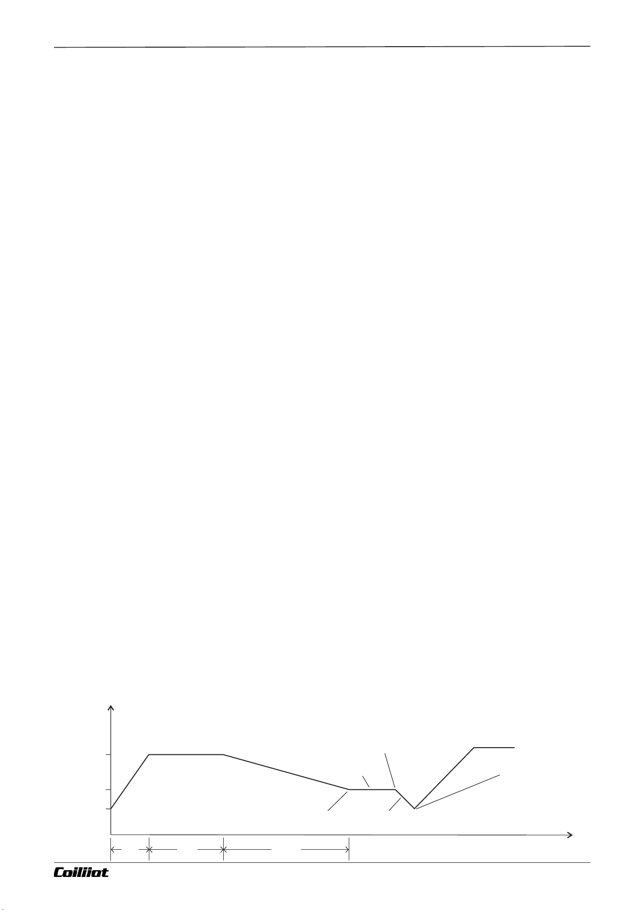
Curve fitting:
Curve fitting is a control technique employed by the AiFUZZY-975 instrument. Because the controlled objects
typically exhibit time lag characteristics, the instrument automatically smooths the linear heating, cooling, and
maintaining temperature curves at their inflection points. The degree of smoothing is related to the system's lag
time t (where t = differentiation time d + control cycle CP). The larger the t, the greater the smoothing, and vice
versa. The shorter the lag time of the controlled object (such as thermal inertia), the better the program control
effect. By processing program curves using curve fitting, overshooting can be avoided.
Note: The characteristics of curve fitting cause program control to generate a fixed negative deviation during linear
heating and a fixed positive deviation during linear cooling. The magnitude of this deviation is proportional to the
lag time (t) and the heating (cooling) rate. This is a normal phenomenon.
13.2 Programming and operation (For AiFUZZY-975 only)
13.2.1 Slop Mode(PSYS : B=0)
Parameter Setting:
- PSYS.B = 0: When set to 0, the program arrangement follows a temperature–time–temperature format. This means
that each program segment is defined by setting a target temperature, the time to reach the next temperature, and
the subsequent target temperature. The units for the temperature setpoint are the same as the measured value
(*PV*), and the time can be set in either minutes or hours.
Functionality:
In Slope Mode, if the program runs to the last segment defined by the *PrSn* parameter and the final segment is
neither a stop command nor a jump command (time settings in the following sections are editable), the program will
automatically end after maintaining the set temperature for the specified duration.
Example Program:
The following is an example of a 5-segment program that includes linear heating, constant temperature, linear
cooling, jump loop, preparation, and pause:
1. Segment 1: - Sp1 = 100.0°C (arbitrary value) - t1 = -0.1
- Description: Specifies the use of PID parameter group 1 (if the current *PIdn* is already 1, this step can be
omitted).
2. Segment 2: - Sp2 = 100.0°C - t2 = 30.0 minutes
- Description: Begins linear heating from 100°C to *SP2* over 30 minutes with a heating slope of 10°C per minute.
3. Segment 3: - Sp3 = 400.0°C - t3 = 60.0 minutes
- Description: Maintains a constant temperature of 400°C for 60 minutes.
4. Segment 4: - Sp4 = 400.0°C - t4 = 120.0 minutes
- Description: Cools down to *SP4* over 120 minutes with a cooling slope of 2°C per minute.
5. Segment 5: - Sp5 = 160.0°C - t5 = 0.0 minutes
- Description: Cools down to 160°C and enters a pause state. To proceed to the next segment, the user must
execute the run command.
6. Segment 6: - Sp6 = 160.0°C - t6 = -1.0
- Description: Jumps back to Segment 1 to start the loop from the beginning.
Operational Details:
In this example, after Segment 5 jumps back to Segment 1, the temperature is set to 160°C while *SP1* is 100°C.
Since these temperatures do not match and Segment 5 is a jump segment, the program enters the preparation state.
The preparation function first adjusts the temperature to within the deviation alarm limit (e.g., to 105°C if the upper
deviation alarm is set to 5°C) before initiating the heating process in Segment 1. This ensures smooth and accurate
temperature control as depicted in the accompanying diagram.
Advantages of Temperature–Time Programming:
- Wide Range of Slope Settings: Allows for extensive flexibility in setting heating and cooling slopes.
- Unified Format: Both heating and constant temperature segments use a consistent setup format, making it easier
to learn and configure.
- Flexible Curve Configuration: Enables the creation of continuous heating segments with varying slopes to
approximate complex heating functions or consecutive constant temperature segments.
Notes:
- Negative Slope Setting (t1 = -0.1): Indicates a specific operational mode or configuration, which may relate to the
initial PID settings or other control parameters.
- Preparation and Measurement Start Functions: These functions enhance program execution efficiency and
reliability by handling discrepancies between measured values and setpoints, especially after power interruptions or
unexpected events.
℃
Time (min)
Loop from step 1
6.jump segment
alarm1 off
5.paise segment
3.cooling segment
2.constant temp. segment
1. Heating segment
4.jump segment
alarm1 on
preparation segment:
no timing
1206030
0
100
160
400
Temp
Page 38/44 pages in total A FUZZY-915/975 9- i Technical Manual_Version number: EN-V 01
Chapter 13 AiFUZZY-975 programming control

13.2.2 Platform Mode
Setting the parameter PSYS.B = 1 selects Platform Mode, which is suitable for applications that do not require
separate settings for heating and cooling slopes. This mode simplifies programming and allows more efficient
use of program segments. In Platform Mode, each program segment follows a temperature–time–temperature
format, where each segment defines a set temperature and the duration to maintain that temperature.
Additionally, the rAtE parameter can be used between segments to define a heating rate limit. If rAtE is set to 0, it
indicates full-speed heating. Since the heating time becomes uncertain and may occupy the holding time,
enabling the rdy (Preparation) function ensures accurate holding times.
13.2.3 Setting Program Setpoints and Time
Each program segment includes a setpoint and a time value. The range of setpoint values is limited by SPL and
SPH, ranging from -999°C to +3200°C, representing the temperature to be controlled (°C) or a linearly defined
unit. The time value not only indicates the running time but also has special control functions. Positive time
values represent running time, while negative time values represent jump commands, with the meanings as
follows:
- Time Range: -122.0 to 3200
- tXXX = 0.1 to 3200: Represents running time values.
- tXXX = 0.0, -0.1 to -122.0: Represents jump commands.
Commands for t:
- 0.0: The instrument enters a hold state at this segment, pausing the program and stopping the timer.
- -121.0: Executes a STOP operation, entering the stopped state.
- -XXX.1: Uses PID parameter group 1.
- -XXX.2: Uses PID parameter group 2.
- -XXX.3: Uses PID parameter group 3.
- -XXX.4: Triggers AL1 action.
- -XXX.5: Releases AL1.
- -XXX.6: Triggers both AL1 and AL2 actions.
- -XXX.7: Releases both AL1 and AL2.
- -XXX.8: Outputs a 0.5-second pulse action on AL1 and continues to the next segment. However, if Alarm 1 is
already active—whether triggered by an event output or an alarm—the pulse action is canceled, and Alarm 1
remains active.
Examples:
- t-1 = -0.1: When running Segment 1, it uses PID parameter group 1, and the PIDn parameter is automatically set
to 1.
- t-7 = -11.2: When running Segment 7, it jumps to Segment 11 and uses PID parameter group 2, automatically
setting PIDn to 2.
- t-5 = -0.4: When running Segment 5, it triggers AL1 action and jumps to Segment 1.
- t-9 = -0.8: When running Segment 9, it outputs a 0.5-second pulse action on AL1 and continues to Segment 10.
Note: Except when executing a run operation or encountering a jump segment during power-on, the program
allows a maximum of two consecutive jumps during program execution. If three or more consecutive jumps
occur, the program automatically pauses execution (i.e., the instrument inserts a pause operation during the
third consecutive jump). An external run operation is required to resume from the paused state. Important: If a
jump segment directs the program to itself (e.g., t-6 = -6), the pause state cannot be cleared, rendering the
segment ineffective.
13.2.4 Multi-PID Application Case Study
Example Program:
1. Segment 1:
- Sp1 = Any value (e.g., 100.0°C)
- t1 = -0.1
- Description: Specifies the use of PID parameter group 1 (PIDn parameter automatically set to 1).
2. Segment 2:
- Sp2 = 100°C
- t2 = 30.0 minutes
- Description: Begins linear heating from 100°C to SP3 over 30 minutes with a heating rate of 10°C per minute.
3. Segment 3:
- Sp3 = 400°C
- t3 = 60.0 minutes
- Description: Maintains a constant temperature of 400°C for 60 minutes.
4. Segment 4:
- Sp4 = 400°C
- t4 = -0.2
- Description: Specifies the use of PID parameter group 2 (PIDn parameter automatically set to 2).
Page 39/44 pages in total A FUZZY-915/975 9- i Technical Manual_Version number: EN-V 01
Chapter 13 AiFUZZY-975 programming control

5. Segment 5:
- Sp5 = 400°C
- t5 = 80 minutes
- Description: Heats from 400°C to 800°C over 80 minutes with a heating rate of 5°C per minute.
6. Segment 6:
- Sp6 = 800°C
- t6 = -0.8
- Description: At 800°C, AL1 outputs a 0.5-second pulse action and continues to the next segment (Segment 7).
7. Segment 7:
- Sp7 = 800°C
- t7 = 120.0 minutes
- Description: Maintains a constant temperature of 800°C for 120 minutes.
8. Segment 8:
- Sp8 = 800°C
- t8 = -0.3
- Description: Continues to the next segment, specifying the use of PID parameter group 3 (PIDn parameter
automatically set to 3).
9. Segment 9:
- Sp9 = 800°C
- t9 = 60.0 minutes
- Description: Heats from 800°C to 1220°C over 60 minutes with a heating rate of 7°C per minute.
10. Segment 10:
- Sp10 = 1220°C
- t10 = 60 minutes
- Description: Maintains a constant temperature of 1220°C for 60 minutes.
11. Segment 11:
- Sp11 = 1220°C
- t11 = -121.0
- Description: Executes a STOP operation, halting control outputs and stopping the program. To rerun the
program, press the key for 2 seconds to execute the RUN operation, restarting the loop from the beginning.
Operational Flow:
- Looping Mechanism: After Segment 5 jumps back to Segment 1, the temperature is set to 160°C, while SP1 is
100°C. Since these temperatures do not match and Segment 5 is a jump segment, the program enters the
preparation state. The preparation function first adjusts the temperature to within the deviation alarm limit (e.g.,
to 105°C if the upper deviation alarm is set to 5°C) before initiating the heating process in Segment 1. This
ensures smooth and accurate temperature control as depicted in the accompanying diagram.
Advantages of Temperature–Time Programming:
- Wide Range of Slope Settings: Allows extensive flexibility in setting heating and cooling slopes.
- Unified Format: Both heating and constant temperature segments use a consistent setup format, making it
easier to learn and configure.
- Flexible Curve Configuration: Enables the creation of continuous heating segments with varying slopes to
approximate complex heating functions or consecutive constant temperature segments.
13.2.5 Self-Tuning Program Setup Method
Example: Tuning PID Group 1 with a self-tuning target value of 400°C.
Segment 1:
-Sp1: Any value
-t1: -0.
-Description: Specifies the use of PID parameter group 1 for the next segment. (If tuning PID parameter group 2,
set t1 = -0.2; if tuning PID parameter group 3, set t1 = -0.3).
Segment 2:
-Sp2: 400°C
-t2: 100.0 (t2 can be any positive value)
-Description: Sets the self-tuning target value to 400°C.
Segment 3:
-Sp3: 400°C
-t3: -1.0
-Description: Jumps back to Segment 1, ensuring the program maintains a constant temperature of 400°C.
Page 40/44 pages in total A FUZZY-915/975 9- i Technical Manual_Version number: EN-V 01
Chapter 13 AiFUZZY-975 programming control
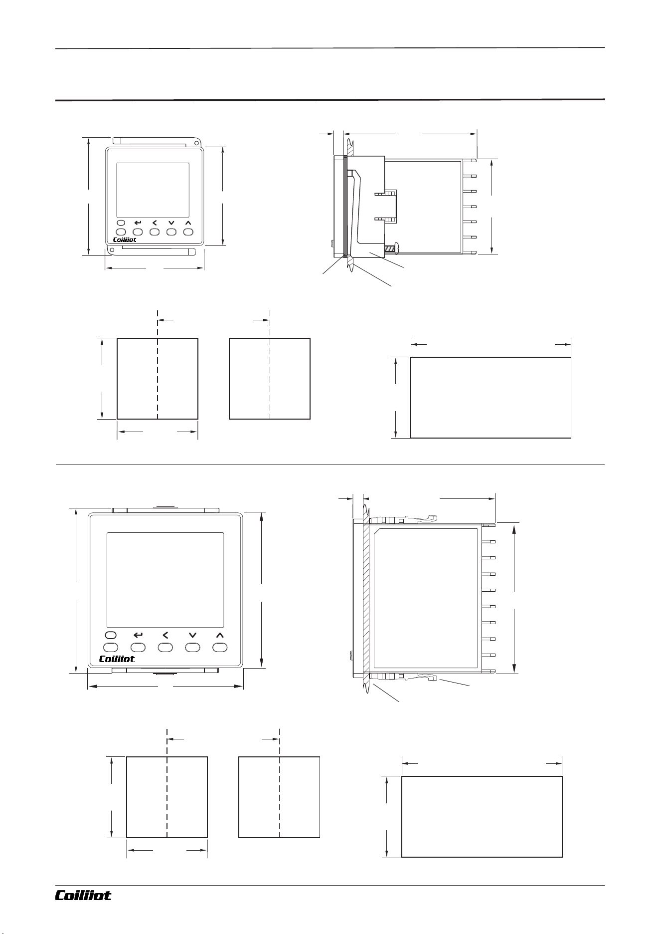
Page 41/44 pages in total A FUZZY-915/975 9- i Technical Manual_Version number: EN-V 01
Chapter 14 Dimensions and installation instructions
Waterproof sealing ring
(Accessory, purchased
separately)
Mounting Adapter(Accessory)
Mounting Adapter(Accessory)
45
45
68
68
+0.6
+0.6
+0.6
+1.0
+1.0
+0.6
-0
-0
-0
-0
-0
-0
45
68
+0.6
+0.6
-0
-0
68
60
4.7
65
4.7
45
G-types panel
D-types panel
Indicates the cross-section of the cabinet panel.
The thickness of the panel must be 1 to 5mm
Indicates the cross-section of the cabinet panel.
The thickness of the panel must be 1 to 5mm
78
72
72
48
58
48
■14.Dimensions and installation instructions(mm)
Single Mounting Hole Dimensions
Single Mounting Hole Dimensions
SV
PV
F
AiFUZZY-900
PV
SV
F
AiFUZZY-900
(48XNumber of units -2. 5)
(48XNumber of units -2. 5)
When tightly installed
When tightly installed
Minimum 60 for
multiple installations
Minimum 100 for
multiple installations
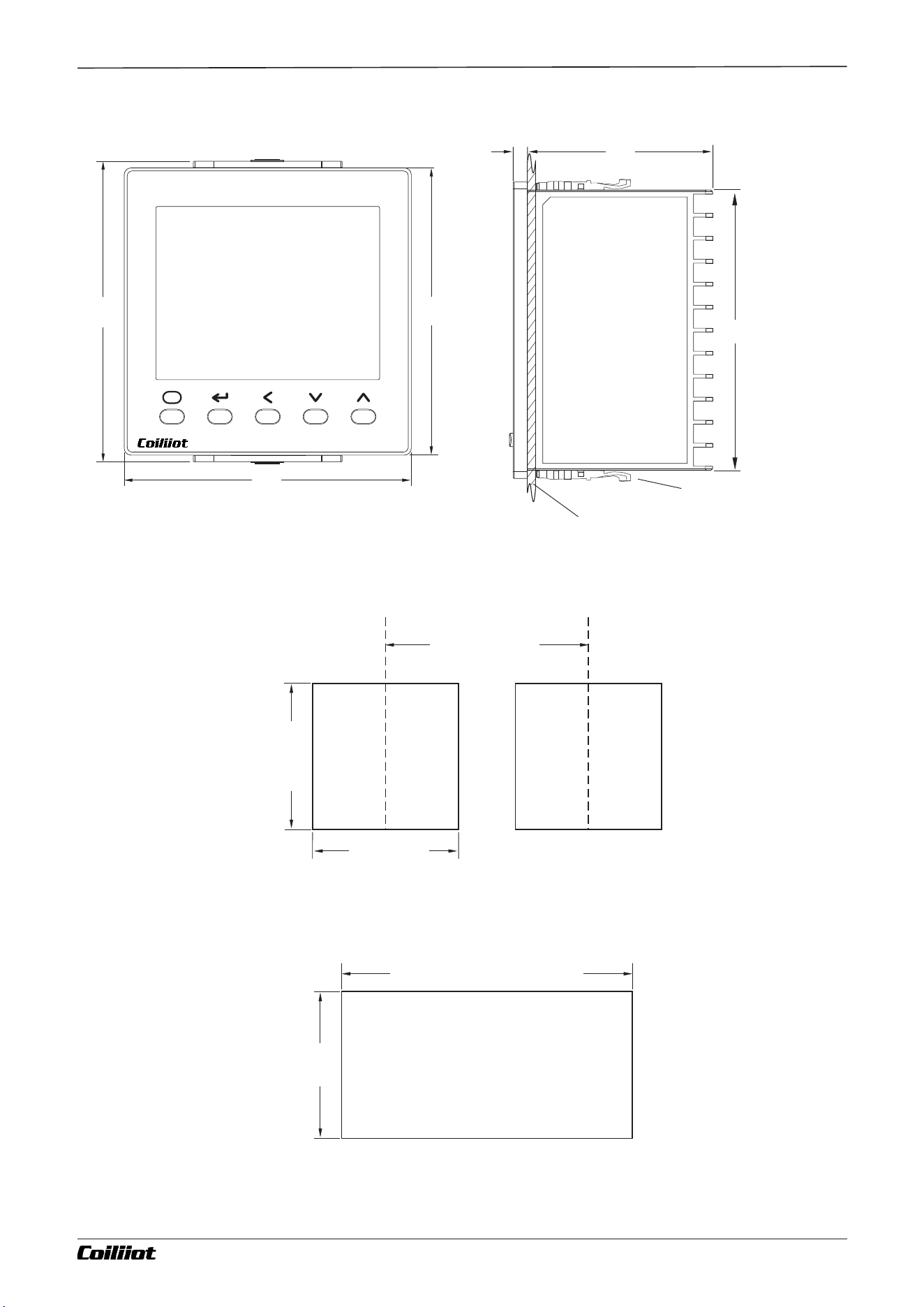
Page 42/44 pages in total A FUZZY-915/975 9- i Technical Manual_Version number: EN-V 01
Mounting Adapter(Accessory)
+1.0
-0
Indicates the cross-section of the cabinet panel.
The thickness of the panel must be 1 to 5mm
Single Mounting Hole Dimensions
(48XNumber of units -2. 5)
When tightly installed
Minimum 120 for
multiple installations
A-types panel
92
60
4.7
100
96
96
PV
SV
F
AiFUZZY-900
92
92
+0.6
+0.6
-0
-0
92
+0.6
-0
Chapter 14 Dimensions and installation instructions
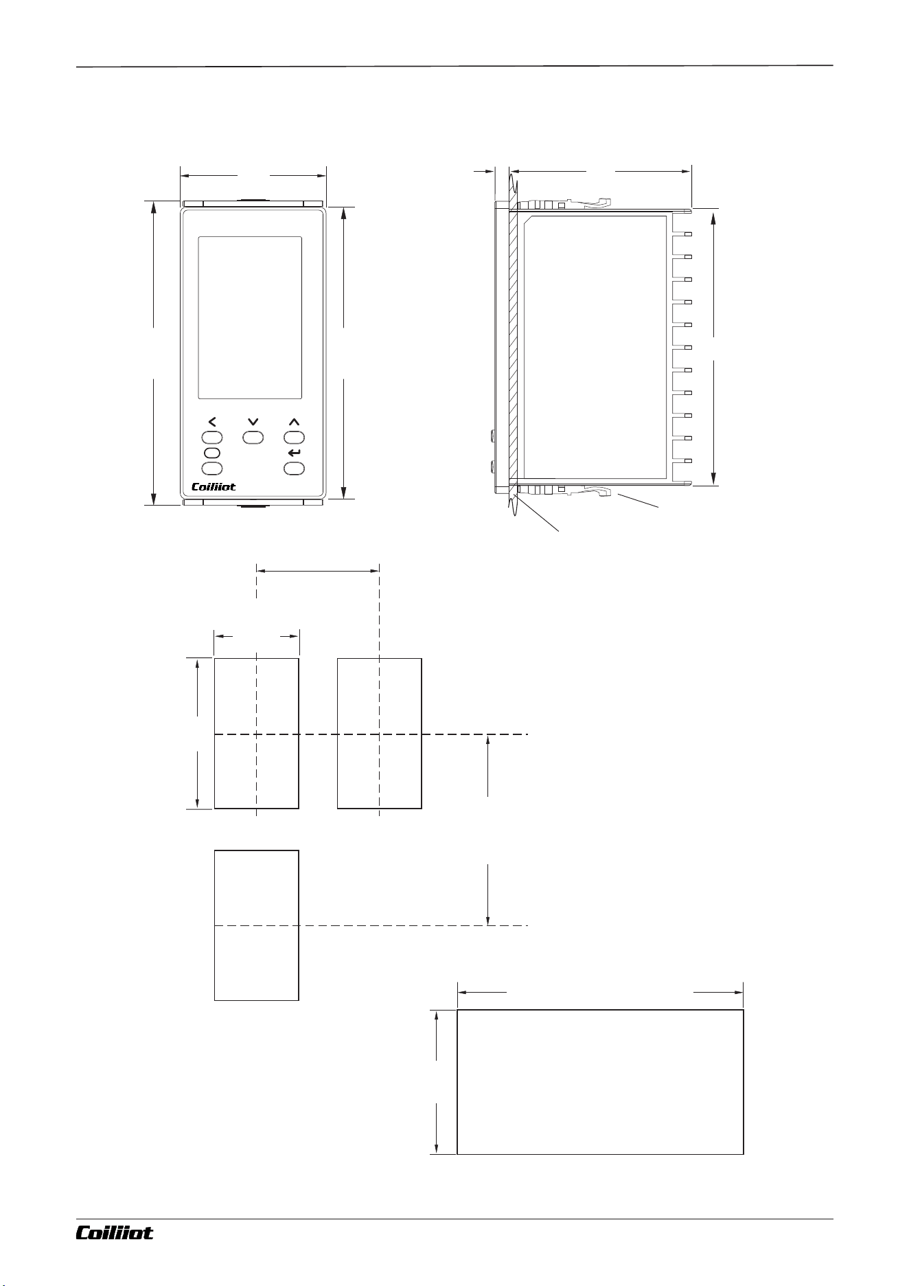
Page 43/44 pages in total A FUZZY-915/975 9- i Technical Manual_Version number: EN-V 01
E-types panel
PV
SV
MV
F
AiFUZZY-900
48
100
96
92
60
4.7
45
+0.6
-0
92
+0.6
-0
92
+0.6
-0
Mounting Adapter(Accessory)
+1.0
-0
Indicates the cross-section of the cabinet panel.
The thickness of the panel must be 1 to 5mm
Single Mounting Hole Dimensions
(48XNumber of units -2. 5)
When tightly installed
Minimum 60 for
multiple installations
Minimum 120 for
multiple installations
Chapter 14 Dimensions and installation instructions
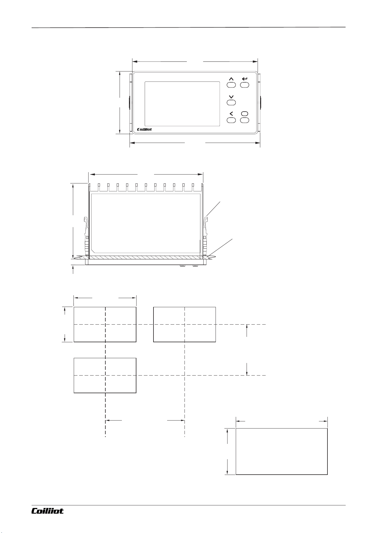
Page 44/44 pages in total A FUZZY-915/975 9- i Technical Manual_Version number: EN-V 01
F-types panel
96
100
48
92
60
4.7
PV
SV
F
AiFUZZY-900
45
+0.6
-0
92
+0.6
-0
45
+0.6
-0
Mounting Adapter(Accessory)
+1.0
-0
Indicates the cross-section of the cabinet panel.
The thickness of the panel must be 1 to 5mm
Single Mounting Hole Dimensions
(48XNumber of units -2. 5)
When tightly installed
Minimum 60 for
multiple installations
Minimum 120 for
multiple installations
Chapter 14 Dimensions and installation instructions