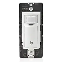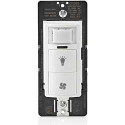
Combination Single Pole Humidity Sensor
and Fan Controller with Light Switch
Cat. No. DHD05 - INDOOR USE ONLY. 120VAC, 60Hz - Single Pole Only
Fan Load (Blue Wire) = Fan: 1/4 Hp, LED/CFL: 300W, Incandescent/Halogen: 600W, ELV/MLV: 400VA
Light Load (Red Wire) = 150W LED/CFL, 250W Incandescent/Halogen, 200VA Magnetic Low-Voltage, 250VA Electronic Low-Voltage, 2A Resistive
INSTALLATION INSTRUCTIONS
ENGLISH
DI-000-DHD05-02B
WARNINGS:
• TO AVOID FIRE, SHOCK, OR DEATH, TURN OFF POWER AT CIRCUIT
BREAKER OR FUSE AND TEST THAT THE POWER IS OFF BEFORE WIRING!
• TO AVOID PERSONAL INJURY OR PROPERTY DAMAGE, DO NOT install to
control a receptacle or a load in excess of the specified rating.
• To be installed and/or used in accordance with electrical codes and regulations.
• If you are not sure about any part of these instructions, consult an electrician.
CAUTIONS:
• DO NOT attempt to service or repair. There are no user-serviceable components.
• Use this device with COPPER OR COPPER-CLAD WIRE ONLY.
• To avoid damage to the product, DO NOT use disinfecting products, including
foggers, sprays or other types of atomized cleaning agents.
• DO NOT spray liquid onto the product.
• To clean use a damp cloth with mild soap.
WARNING: TO AVOID FIRE, SHOCK, OR DEATH, turn off power at circuit breaker or
fuse and test that the power is off before wiring!
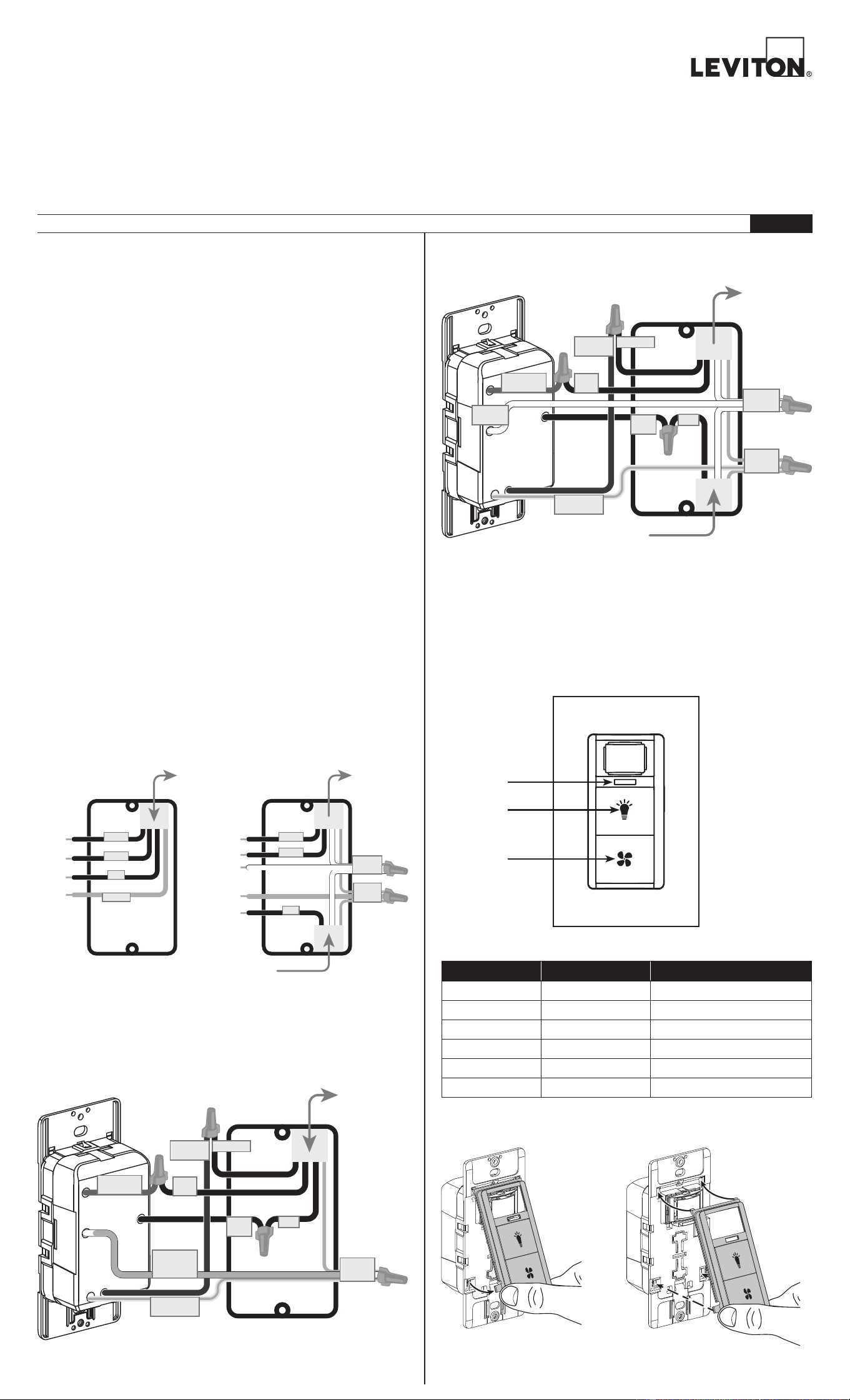
1. Identify your wires (most common):
NOTE: A Neutral wire (if present) or a Ground wire is required for operation.
If the wiring in the wall box does not resemble this configuration, consult
an electrician.
2a. Wire (when Neutral is NOT present)
Working on one connection at a time, connect wires as shown below.
3. Test and Mount
a. Restore power. Wait 10-20
seconds for sensor to power up.
b. The GREEN light will blink once every 5 seconds during power up.
c. Push the button to test the Load.
d. Turn off power at circuit breaker before completing the installation.
e. Gently push wires into wall box. Screw light control to box.
f. Install wallplate.
g. Restore power.
You Will Need:
• Slotted/Phillips screwdriver
• Electrical tape
• Cutters
• Pliers
LED Color LED Status
Power Up
Green Blink once every 5 seconds
Load OFF
OFF OFF
Load ON
Green ON
Bypass Mode
Green Blink twice every 2 seconds
Test Mode Red Blink once every 2 seconds
Program Mode
Red/Green/Amber See Programming Table
Operation
NOTE: When the RED and GREEN LEDs are on at the same time, the light will
appear as an AMBER color.
Available in White (W), Light Almond (T), Ivory (I), Brown (B), Black (E), Grey (G),
(DHDKT-1Lx)
Location
Features
Installation
Leviton's Combination Single Pole Humidity Sensor and Fan Controller with Light
Switch senses the humidity of your bathroom and turns your bath fan or fan/light ON
when the humidity gets too high. This reduces condensation in your bathroom and
increases ventilation when used in other household spaces.
• Compatible with Incandescent, LED, CFL, and ELV/MLV loads
• Sensitivity adjustment.
• Built-in countdown timer feature for manual operation.
• Automatic ventilation/air circulate mode for continuous operation, with hourly
preset time-outs.
• With Zero Cross turn-ON technology to extend the life of switching relays.
• Advanced sensing enhances detection when the room is occupied and minimizes
false triggers when unoccupied.
• Color change kits available in white, light almond, ivory, black, brown, and gray.
For bathroom applications, the device should be placed at a level that can detect
steam. Placing the detector directly above a heater or near drafts is
NOT recommended.
NOTE: DO NOT use to control a fan/light combination where the fan/light is the only
means of illumination.
NOTE: The Humidity Sensor and Fan Control will not eliminate condensation and
must be used with a properly sized ventilation fan in an enclosed space.
No Neutral wire With Neutral wire
LOAD 1
LOAD 1
LOAD 2
LOAD 2
LINE
LINE
GROUND
GROUND
To and From
To and From
Fan/Light
Fan/Light
GROUND
GROUND
From
From
Branch Circuit
Branch Circuit
LOAD 1
LOAD 1
LOAD 2
LOAD 2
LINE
LINE
NEUTRAL
NEUTRAL
To Fan and Light
To Fan and Light
2b. Wire (when Neutral is present)
Remove the Green sleeve from the White wire. Working on one connection at a
time, connect wires as shown below.
Fan
(Press button
to turn ON)
Light
(Press button
to turn ON)
LED
(Red/Green)
From
From
Branch Circuit
Branch Circuit
FAN LOAD
FAN LOAD
LINE
LINE
LINE
LINE
(Black)
(Black)
FAN LOAD
FAN LOAD
(Blue)
(Blue)
GROUND
GROUND
(Green/Yellow)
(Green/Yellow)
GROUND
GROUND
LIGHT
LIGHT
LOAD
LOAD
To Fan and Light
To Fan and Light
NEUTRAL
LIGH
T LOAD
LI
G
H
T
LOAD
R
ED
R
ED
GROUND
GR
O
U
N
D
GRN
SLEEVE
GR
N
S
L
E
E
V
E
N
EU
TR
AL
N
EU
TR
A
L
WHITE
W
H
I
T
E
WITHOU
T
N
ET
U
R
AL
,
W
I
TH
O
U
T
N
E
T
U
R
A
L
,
D
EV
IC
E
M
U
S
T
B
E
D
E
V
I
CE
M
U
S
T
BE
GR
OUN
DED
TO
F
UNC
TION
.
G
R
OU
N
D
E
D
T
O
FUN
C
TI
O
N
.
GROUND
GR
O
U
N
D
G
RN/
YL
G
R
N
/YL
F
AN
L
OA
D
F
AN
L
OAD
BL
UE
B
L
U
E
L
I
N
E
L
I
N
E
BL
AC
K
BL
A
C
K
NEUTRAL
(White)
LIGHT LOAD
LIGHT LOAD
(Red)
(Red)
FAN LOAD
FAN LOAD
LINE
LINE
LINE
LINE
(Black)
(Black)
FAN LOAD
FAN LOAD
(Blue)
(Blue)
GROUND
GROUND
(Green/Yellow)
(Green/Yellow)
GROUND
GROUND
GROUND
GROUND
(Green
(Green
sleeved wire)
sleeved wire)
LIGH
T
L
O
AD
LI
G
H
T
L
O
AD
R
ED
R
E
D
G
ROUND
G
R
OU
N
D
GRN
SLEEVE
GR
N
S
L
E
E
V
E
N
EU
T
R
AL
N
EU
T
R
A
L
WHI
T
E
W
H
I
T
E
WITH
OU
T
N
ETUR
AL
,
W
I
TH
O
U
T
N
E
T
U
R
A
L
,
DEV
IC
E
M
U
S
T
B
E
D
E
V
I
C
E
M
U
S
T
B
E
GR
OU
N
D
ED
TO
FU
NC
TION.
G
R
OU
N
D
E
D
T
O
FU
N
C
TI
O
N
.
GROUND
GR
O
U
N
D
GRN/
YL
G
R
N
/
Y
L
F
AN
L
OA
D
F
A
N
L
OA
D
BL
UE
B
L
U
E
LINE
BL
AC
K
B
L
A
C
K
LIGHT LOAD
LIGHT LOAD
(Red)
(Red)
LIGHT
LIGHT
LOAD
LOAD
To and From
To and From
Fan/Light
Fan/Light
Changing Your Device Color
Remove Replace
© 2022 Leviton Mfg. Co., Inc.
What to do if...
Setting Types and Options (defaults are in bold)
Setting 1 Setting 2 Setting 3
Option
Number
Time Period / Time
that Fan will Stay ON
(GREEN LED will blink)
Sensitivity to Humidity
(AMBER [Red and Green]
light will blink)
Device Operating
Mode (RED LED
will blink)
Option 1
(1 blink)
10 minutes
Auto-ON: Maximum Sensitivity
Humidistat: 35% RH
Bath Fan (Auto-
ON/OFF)
Option 2
(2 blinks)
20 minutes
Auto-ON: High Sensitivity
Humidistat: 50% Relative
Humidity (RH)
Air Cycle
Option 3
(3 blinks)
30 minutes
Auto-ON: Medium Sensitivity
Humidistat: 65% RH
Humidistat
Option 4
(4 blinks)
45 minutes
Auto-ON: Low Sensitivity
Humidistat: 80% RH
All settings
to Default
Operating Mode Descriptions
Operations When/Where to Use Your Fan Will...
AUTOMATIC
(Auto-ON/
Auto-OFF)
For bathrooms and areas
where significant changes
in humidity can occur.
Fan will turn ON when the humidity
rises above the Sensitivity setting (Low,
Medium, High, or Max.). The fan will
stay ON for
the Time Period you set.
After the fan turns OFF, if the humidity
is still above the threshold, it will
retrigger and turn the fan ON for half
the Time Period set (up to a maximum
of 2 retriggers).
MANUAL
(Pressing the
button)
Any time you want to turn
the fan ON/OFF.
Fan will turn ON and stay ON for the
Time Period you set. Fan will turn OFF
for a minimum of 2 minutes and then
resume Auto-ON monitoring.
BYPASS
(Hold FAN button
for 5 seconds)
• To temporarily disable
the Auto-ON functionality
of the sensor.
•
To exit Bypass, press the
FAN button.
Fan will NOT turn ON automatically.
The GREEN light will blink twice every
2 seconds.
BATH FAN MODE
Operations When/Where to Use Your Fan Will...
AUTOMATIC
(Air Cycle above
RH set point)
Basements, laundry rooms,
and damp rooms.
When the Relative Humidity (RH) is
greater than or equal to the Humidistat
setting (35%, 50%, 65%, or 80%), the
fan will run for Time Period you set
(X minutes). When the Time Period
expires, the fan will turn OFF for the
remainder of the hour.
NOTE: Fan will run for X minutes
every hour, until the RH is less than the
humidistat setting.
MANUAL
(Pressing the
button)
Any time you want to turn
the fan ON/OFF.
If the user turns the fan ON manually,
the device will act as if that was the
start of a new hour-long cycle. If the
user turns the fan OFF manually, the
device will enter the OFF period for the
remainder of the hour.
BYPASS
(Hold FAN button
for 5 seconds)
• To temporarily disable the
Humidistat functionality
of the sensor.
• To exit Bypass, press
FAN button.
Fan will NOT turn ON automatically.
The GREEN light will blink twice every
2 seconds.
Operations When/Where to Use Your Fan Will...
AUTOMATIC
Basements, bathrooms,
and rooms requiring
regular ventilation
(meets ASHRAE 62,2).
Run every hour, for the Time Period
you set (X minutes).
Ex: If the fan is set to be ON for 20
minutes, it will be OFF for 40 minutes
(1 hour minus 20 minutes).
MANUAL
(Pressing the
button)
Any time you want to turn
the fan ON/OFF.
If the user turns the fan ON manually,
the device will act as if that was the
start of a new hour-long cycle. If the
user turns the fan OFF manually, the
device will enter the OFF period for the
remainder of the hour.
BYPASS
(Hold FAN button
for 5 seconds)
• To temporarily disable
the air cycle.
• To exit Bypass, press
FAN button.
Fan will NOT cycle air periodically.
The GREEN light will blink twice every
2 seconds.
• If the humidity sensor false triggers, reduce the Sensitivity to a lower level.
• If the sensor does not trigger, or it turns the fan ON late, increase the Sensitivity level.
• If the fan turns OFF too soon, increase the time in the Time Period setting.
• If the fan turns ON when the Light button is pressed, then the device was wired
incorrectly. Rewire and switch the Red and Blue wires.
AIR CYCLE MODE
HUMIDISTAT MODE
Programming
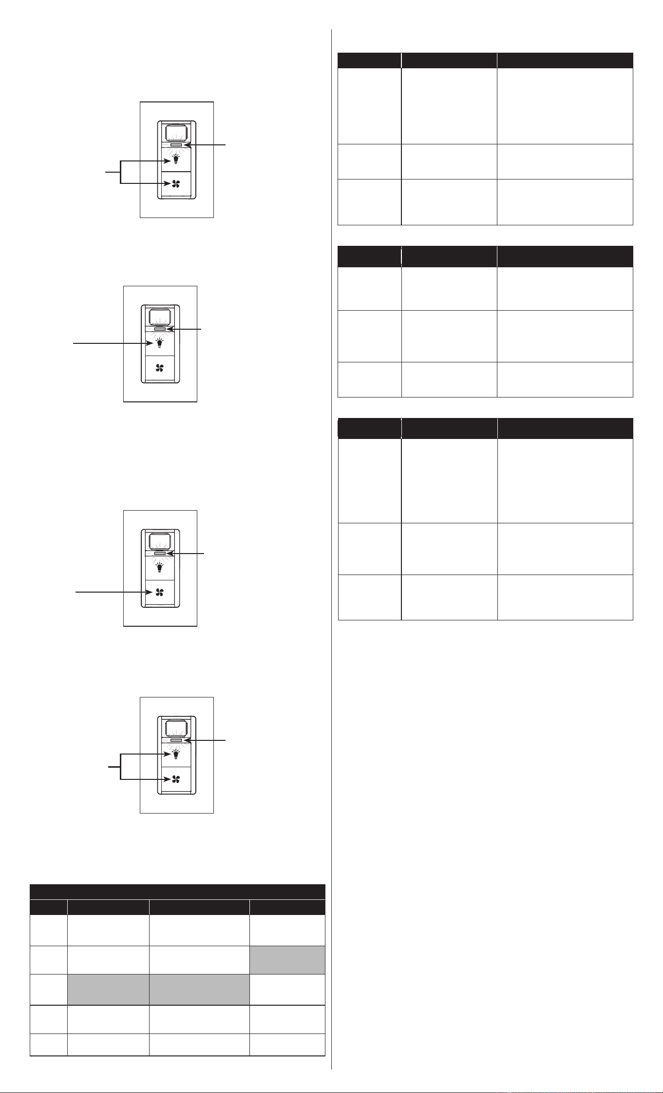
2. Enter Programming Mode. Make sure the fan is OFF.
a. Hold the LIGHT and
FAN buttons down for
at least 5 seconds.
a. Hold either the
LIGHT or FAN button
down for 5 seconds.
a. To advance from one
setting to the next, press
the LIGHT button once
each time.
NOTE: The settings will
cycle from 1 to 2 to 3,
and then back to 1.
a. To advance from one
option to the next, press
the FAN button once
each time.
NOTE: The options will
cycle from 1 to 2 to 3 to
4, and then back to 1.
• Setting 1: Time Period / Time
that Fan Will Stay ON
(GREEN light will blink if selected)
•
Setting 2: Sensitivity to Humidity
(AMBER [Red and Green] light will
blink if selected)
•
Setting 3: Device Operating Mode
(RED light will blink if selected)
b. A GREEN, AMBER, or RED light
(depending on which setting you
selected) will blink to indicate the
option you selected.
b.
A GREEN light will appear
and stay ON for 5 seconds,
indicating that you have
successfully entered
Programming Mode.
b. A GREEN light will
appear and stay ON for
5 seconds, indicating that
you have successfully
exited the Programming
Mode and your settings
have been saved.
5. Save your settings and exit the Programming Mode.
4. Change the option within each setting (see the table below for the options).
NOTE: The default option for each setting is listed in the table in bold.
• Option 1 = 1 blink/second
• Option 2 = 2 blinks/second
• Option 3 = 3 blinks/second
• Option 4 = 4 blinks/second
3. Select each setting you wish to change, one at a time, to program the option
desired (see table below).
NOTES:
• After 60 seconds of inactivity, the device will automatically exit Programming Mode
and setting changes will not be saved.
• When you enter Programming Mode again, you will start at the Time Period setting,
in the last saved option row (default is Option 2: 20 minutes).
NOTE: Once you enter Programming Mode, multiple settings can be changed
before saving and exiting.
1. Using the tables in the right column, determine the appropriate Operating Mode for
your application needs.
Test Mode
1. To test that your device is working properly, hold the LIGHT button down for 5
seconds. A RED light will blink once every 2 seconds. You are now in Test Mode.
2. Blow humid air into the sensor. During Test Mode, an increase in humidity will trigger
the load for 5 seconds. NOTE: If the device does not trigger, then the room may be
too large or the device may be too far away from a source of humidity.
3.
Exit Test Mode by pressing the FAN button. Test Mode will also time-out after 2 minutes.
For Technical Assistance Call: 1-800-824-3005 (USA Only) or
1-800-405-5320 (Canada Only) www.leviton.com
FCC AND INDUSTRY CANADA COMPLIANCE STATEMENT: This device complies with Part 15 of the FCC
Rules and ISED License-exempt RSS standard(s). Operation is subject to the following two conditions: (1) This
device may not cause harmful interference, and (2) This device must accept any interference received, including
interference that may cause undesired operation. Changes or modifications not expressly approved by the
party responsible for compliance could void the user's authority to operate the equipment. To comply with FCC/
ISED RF exposure limits for general population / uncontrolled exposure, the antenna(s) used for this transmitter
must be installed to provide a separation distance of at least 20 cm from all persons and must not be co-located
or operating in conjunction with any other antenna or transmitter different from that to which the receiver is
connected.
FCC CAUTION: Any changes or modifications not expressly approved by Leviton Manufacturing Co., Inc., could
void the user's authority to operate the equipment.
FOR CANADA ONLY
For warranty information and/or product returns, residents of Canada should contact Leviton in writing at Leviton
Manufacturing of Canada Ltd to the attention of the Quality Assurance Department, 165 Hymus Blvd, Pointe-
Claire (Quebec), Canada H9R 1E9 or by telephone at 1-800-405-5320.
LIMITED 5 YEAR WARRANTY
For Leviton’s limited product warranty, go to www.leviton.com. For a printed copy of the warranty,
call 1-800-824-3005.
Patents covering this product, if any, can be found on www.leviton.com/patents.
Leviton and the Leviton logo are the registered trademarks of Leviton Mfg. Co., Inc.