
N
o
-536 Monaural
Amplifier
Owner’s Manual

ii
FCC Notice
This equipment has been tested and found to comply with the limits for a Class B digital device, pursuant
to Part 15 of the FCC Rules. These limits are designed to provide reasonable protection against harmful
interference in a residential installation. This equipment generates, uses and can radiate radio frequency
energy and, if not installed and used in accordance with the instructions, may cause harmful interference
to radio communications. However, there is no guarantee that interference will not occur in a particular
installation. If this equipment does cause harmful interference to radio or television reception, which can be
determined by turning the equipment off and on, the user is encouraged to try to correct the interference by
one or more of the following measures:
• Reorient or relocate the receiving antenna.
• Increase the separation between the equipment and the receiver.
• Connect the equipment into an outlet on a circuit different from that to which the receiver is connected.
• Consult the dealer or an experienced radio/TV technician for help.
Caution!
Changes or modifications not expressly approved by the party responsible for compliance could void the
user’s authority to operate the equipment.
USA and Canada
This device complies with part 15 of the FCC Rules. Operation is subject to the following two conditions:
(1) This device may not cause harmful interference, and (2) this device must accept any interference received,
including interference that may cause undesired operation.
CAN ICES-3 (B) / NMB-3 (B).
For customer service and product
shipment information, refer to the
website: www.marklevinson.com
Mark Levinson is a registered trademark of Harman International Industries, Incorporated.
Windows, Microsoft and Internet Explorer are registered trademarks of Microsoft Corporation
in the United States and/or other countries.
Other company and product names may be trademarks of the respective companies with
which they are associated.
©2015 Harman International Industries, Incorporated. All rights reserved.
This document should not be construed as a commitment on the part of
Harman International Industries, Incorporated. The information it contains is subject
to change without notice. Harman International Industries, Incorporated, assumes no
responsibility for errors that may appear within this document.
iii
Important Safety Instructions
1. Read these instructions.
2. Keep these instructions.
3. Heed all warnings.
4. Follow all instructions.
5. Do not use this apparatus near water.
6. Clean only with a dry cloth.
7. Do not block any ventilation openings. Install in accordance with the manufacturer’s instructions.
8. Do not install near any heat sources such as radiators, heat registers, stoves or other apparatus that
produce heat.
9. Do not defeat the safety purpose of the polarized or grounding-type plug. A polarized plug has two blades
with one wider than the other. A grounding-type plug has two blades and a third grounding prong. The
wide blade or third prong is provided for your safety. If the provided plug does not t into your outlet,
consult an electrician for replacement of the obsolete outlet.
10. Protect the power cord from being walked on or pinched, particularly at plugs, convenience receptacles
and the point where it exits from the apparatus.
11. Only use attachments and accessories specied by the manufacturer.
12. Use only with the cart, stand, tripod, bracket or table specied by the manufacturer
or sold with the apparatus. When a cart is used, use caution when moving the cart/apparatus
combination to avoid injury or tip over.
13. Unplug this apparatus during lightning storms or when unused for long periods of time.
14. Refer all servicing to qualied service personnel. Servicing is required when the apparatus has been
damaged in any way, such as when the power-supply cord or plug is damaged; liquid has been spilled or
objects have fallen into the apparatus; or the apparatus has been exposed to rain or moisture, does not
operate normally or has been dropped.
15. The MAINS cord is intended to be the safety disconnect device for this apparatus and shall remain readily
operable at all times.
16. Ventilation should not be impeded by covering the ventilation openings with items such as newspapers,
tablecloths, or curtains.
17. No naked ame sources, such as candles, should be placed on the apparatus.
18. Terminals marked with this symbol may be considered HAZARDOUS LIVE, and the external
wiring connected to these terminals requires installation by an INSTRUCTED PERSON or the
use of ready-made leads or cords.
19. This product must be terminated with a three-conductor AC mains power cord that includes an earth
ground connection. To prevent shock hazard, all three connections must ALWAYS be used.
Warning!
To reduce the risk of fire or electric shock, do not expose this apparatus to rain or moisture. The apparatus
shall not be exposed to dripping or splashing. No objects filled with liquids, such as vases, shall be placed
on the apparatus.
Mark Levinson
iv
Safety Terms & Symbols
These terms may appear in this manual:
Calls attention to a procedure, practice, condition or the like that, if not
correctly performed or adhered to, could result in personal injury or
death.
Calls attention to a procedure, practice, condition or the like that, if not
correctly performed or adhered to, could result in damage or destruction
to part or all of the component.
Calls attention to information that is essential to highlight.
These symbols may appear on the product:
Appears on the component to indicate the presence of non-insulated,
dangerous voltage inside the enclosure – voltage that may be sufcient to
constitute a risk of shock.
Appears on the component to indicate important operation and
maintenance instructions included in the accompanying documentation.
Appears on the component to indicate compliance with the EMC
(Electromagnetic Compatibility) and LVD (Low-Voltage Directive)
standards of the European community.
Warning!
Caution!
Note

Nº536 Series Power Amplifier
1
Table of Contents
About This Document .......................................................................................... 2
Introduction ........................................................................................................... 2
Installation Considerations ................................................................................. 4
Power Requirements ............................................................................................ 5
Front Panel ............................................................................................................. 5
Rear Panel .............................................................................................................. 6
Operation ............................................................................................................... 8
Faults & Troubleshooting .................................................................................... 9
Care & Maintenance ............................................................................................ 10
Specifications ........................................................................................................ 11
Declaration of Conformity .................................................................................. 12

Mark Levinson
2
About this document
This User Guide primarily covers the system functions and advanced options
contained in your N
o
-
536. These resources allow you to nely tailor the
behavior and performance of the N
o
-
536 to t your system and listening room.
This document contains general safety and operation instructions for the
amplier. It is important to read this document before attempting to use
this product. Please pay particular attention to safety instructions.
This manual is not intended as a general reference guide for audio or
home theater systems. If you’re uncertain how to set up or maintain your
system, seek the advice of a professional installer or ask your dealer for a
recommendation.
Introduction
Thank you for purchasing the N
o
-
536 monaural amplier. Since 1972,
Mark Levinson
®
has been dedicated to the uncompromising art of sound,
with the guiding principle of musical purity above all else. To achieve
that goal like never before, Mark Levinson engineers scoured company
archives, ultimately developing a proprietary, new, yet familiar amplier
design featuring outstandingly high current and tremendous open-loop
linearity. The result is the Mark Levinson N
o
-
536 Monaural Amplier. This
fully differential, fully discrete monoblock drives virtually any loudspeaker
effortlessly for impeccable imaging, musicality, and openness.
The pursuit of perfect amplication is a well-known theme in high-end audio.
New technologies present new approaches, while looking to the past provides
inspiration for the future. It was in that spirit that the Mark Levinson N
o
-
536
Monaural Amplier was developed: an amplier advised by the traditions and
art of classic amplier design, and infused with modern technology. A fully
discrete, differential, direct-coupled signal path; a highly linear, low-feedback
design; and voltage gain and drive stages operating in class A, are joined by
the modern system integration capabilities provided by Ethernet, RS-232, and
USB for monitoring and network control.
The N
o
-
536’s core design principles are its very high open-loop linearity and
extremely high bias current. Because the amplier circuitry was designed
to have such intrinsically high performance, it requires very little feedback
to achieve impeccably low distortion and enormously wide bandwidth.
Employing unusually high bias current enables superb linearity with wide
bandwidth: nearly immune to the effects of parasitic capacitances, the N
o
-
536
is able to change voltage with unreserved agility. These design principles
create the hallmarks of Mark Levinson amplication: effortlessness, openness,
and unadulterated smoothness throughout the entire frequency range,
regardless of load or listening level.
Mark Levinson takes pride in both the art and science of engineering. To
that end, components are selected based not only on their technical merits,
but also on their sonic capabilities. The Mark Levinson N
o
-
536 Monaural
Amplier contains 12 discrete 15A, 260V, 200W TO-264 bipolar output
Philosophy
Design Principles
Components

Nº536 Series Power Amplifier
3
transistors per output stage (24 total); and 12 discrete 230V, 70MHz TO-220
bipolar driver transistors per output stage (one for each output transistor,
24 total). Its power supply contains eight discrete, high speed, 40A, 250V
TO-220 Schottky rectiers per output stage (16 total) and 18 lter capacitors
per output stage (36 total) for a grand total of 169,200 microfarads of
storage capacitance. The N
o
-
536 also features a custom-designed, low noise
toroidal transformer, rated for 1,800VA total continuous power with separate
secondary windings for each output stage. The output stage and power
supply components are over-specied to offer unsurpassed performance and
reliability. The input stage of the N
o
-
536 contains two matched-pair, low-
noise, high-gain, dual JFET input transistors, which in turn are connected
in a double cascode conguration to bipolar transistors; the combination
of devices offers inherently low distortion and wide bandwidth, as well as
the ability to effortlessly swing large signal voltages. This circuit operates in
a fully balanced, differential conguration and uses discrete TO-126 bipolar
pre-driver transistors to accurately drive the massive output stages.
• Class AB design rated at 400W into 8 ohms and 800W into 4 ohms
• Fully discrete and differential signal path, input to output
• High linearity, low-feedback design for low distortion and
wide bandwidth
• Voltage gain and driver stages operate in class A
• Direct coupled: no capacitors in the signal path
• Custom-designed, low-noise 1800VA toroidal transformer
• High current linear power supplies employing low noise, high speed
discrete Schottky rectiers and multiple paralleled lter capacitors
• Mirror-image symmetrical design
• Four binding posts with Hurricane terminals for standard and bi-wired
loudspeaker connections
• System controls: Ethernet, RS-232, IR input, 12V trigger input and
output, USB
• Power Amplier
• Owner’s Manual
• Handling Gloves (pair)
• Power Cable
Features
Box Contents

Mark Levinson
4
Installation Considerations
The N
o
-
536 requires special care during installation to ensure optimal
performance. Pay particular attention to instructions included in this
section and to precautions included throughout this owner’s manual.
DO save all packing materials for possible future shipping needs.
DO inspect the amplier for signs of damage during shipment. If damage is
discovered, contact your authorized Mark Levinson dealer for assistance in
making appropriate claims.
DO locate and remove the accessory bag from the carton. Make sure it
contains all of the items listed in the “What’s in the Box” table on the
previous page. If not, contact your authorized Mark Levinson dealer.
DO NOT attempt to lift or move the power amplifier without
adequate assistance. The shipping weight of the amplifier exceeds
what a single person should lift alone. To avoid injury or damage to
the unit, at least two people are required to lift or move the amplifier.
Knit white gloves with special gripping surfaces on the palms and
fingers are included with the amplifier. Wear these gloves when
lifting or moving the amplifier.
DO install the power amplier on its own shelf for proper ventilation.
DO install the amplier chassis on a solid, at, level surface.
DO install the power amplier close to associated components to keep
interconnecting cables as short as possible.
DO select a dry, well-ventilated location out of direct sunlight.
DO allow at least 3 to 4 inches (8 to 10cm) of clearance above and on each
side of the amplier for proper heat dissipation.
DO allow at least 6 inches (15cm) of clearance behind the amplier so that
the power cord and cables have space to bend without becoming crimped
or strained.
DO NOT place the amplier chassis on a thick rug or carpet or cover the
amplier with a cloth, as this might prevent proper cooling.
DO NOT obstruct the ventilation holes on the top and bottom of the
chassis or reduce airow through the amplier.
DO NOT place the amplier chassis near low-level components.
The power amplier is capable of producing large output currents and
hence signicant magnetic elds, which can induce noise in sensitive
components.
DO NOT expose the power amplier to high temperatures, humidity,
steam, smoke, dampness, or excessive dust. Avoid installing near radiators
and other heat-producing appliances.
MAKE SURE all components are properly grounded. Do not defeat
the safety purpose of polarized or grounding-type plugs with
“ground-lifter” or “cheater” adapters. Doing so may cause dangerous
voltage to build up between components, which can result in
personal injuries and/or product damage.
Unpacking
Caution!
Placement and
Ventilation
Warning!
Nº536 Series Power Amplifier
5
Power Requirements
The amplier is congured at the factory for 100, 120, or 230 VAC power
operation at 50Hz or 60Hz. Before operating the amplier, ensure that the
power label on the rear panel near the AC input connector indicates the
correct operating voltage.
DO NOT attempt to adjust the operating voltage. Consult a
Mark Levinson dealer if the operating voltage is incorrect or must be
changed for relocation purposes.
Different operating voltages may require the use of different power
cords and/or attachment plugs. Contact a Mark Levinson dealer for
additional assistance.
This amplier is capable of passing remarkable sound at exceptional power
levels. Depending on listening habits, loudspeaker demands, and the number
of power ampliers present in the system, it is possible that the electrical
service may become the limiting performance factor of your system.
If this case occurs, consider installing a dedicated AC circuit for the system.
Contact a licensed electrician for assistance. If more than one AC circuit is
providing power to the system, contact a licensed electrician to ensure that
all components are operating with the same solid, low-impedance ground
reference.
Building regulations and electrical codes differ from location
to location, making it impossible to anticipate the requirements
of amplifier high-current AC circuits. Contact a local, licensed
electrician for further information.
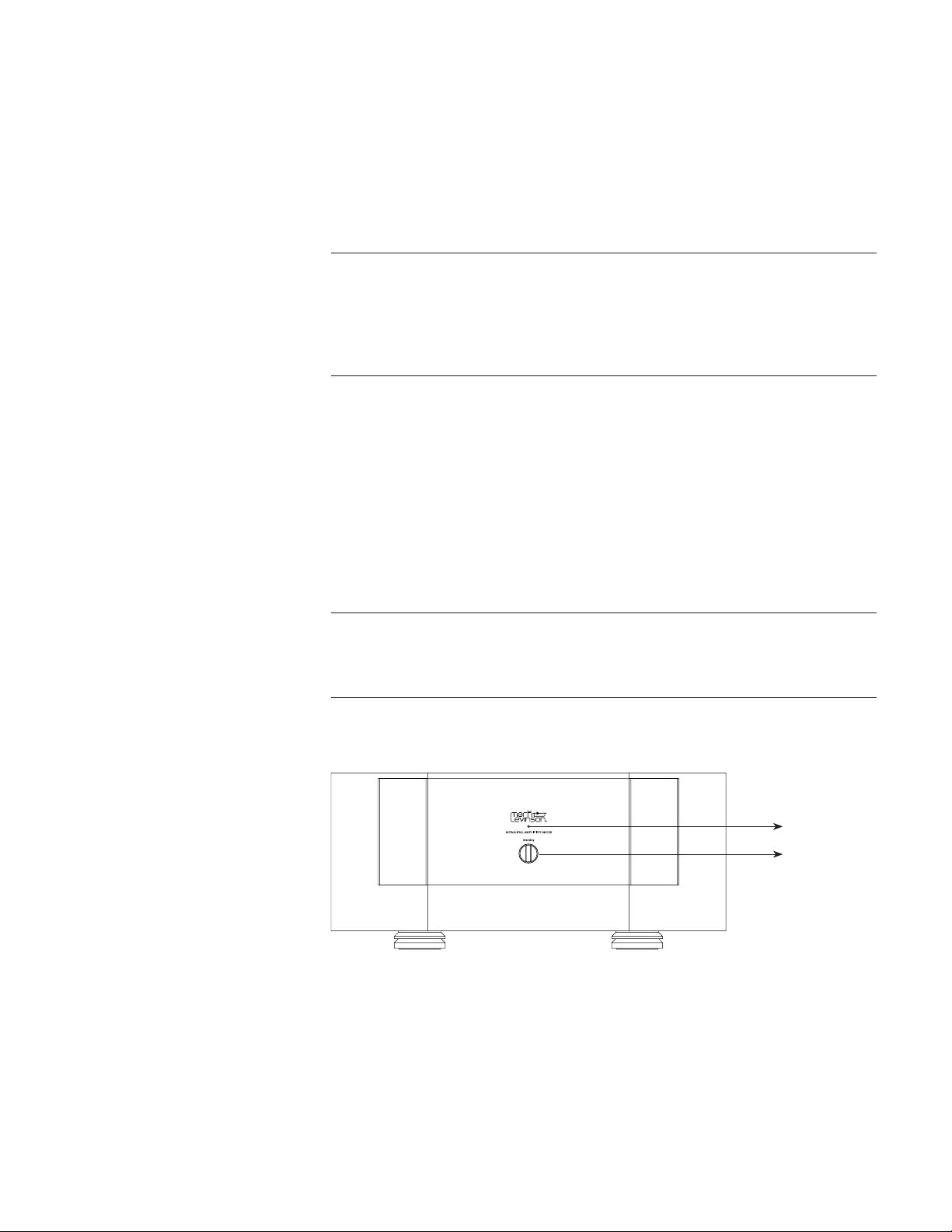
Front Panel
Status LED
Standby button
Toggles the amplier between On and the selected Standby mode when the
rear-panel Power Switch is turned on.
Indicates the operating state of the amplier and provides basic diagnostic
information if a fault condition occurs. The table below identies the
basic behavior of the Status LED. More information on each status can be
accessed on the amplier’s web interface.
Caution!
Caution!
Standby Button
Status LED
Mark Levinson
6
LED Lit Steadily Flashing
Red
Amplier powered on,
normal operation
Amplier in Standby
White
Amplier shut off due
to non-recoverable fault
condition. Switch power off
from the rear panel to exit
this state.
Amplier in Safe Mode due to
a recoverable fault condition.
Once cleared, amplier will
enter Standby, indicated by red
ashing Status LED.
Blue
Starting up from reset Installing update
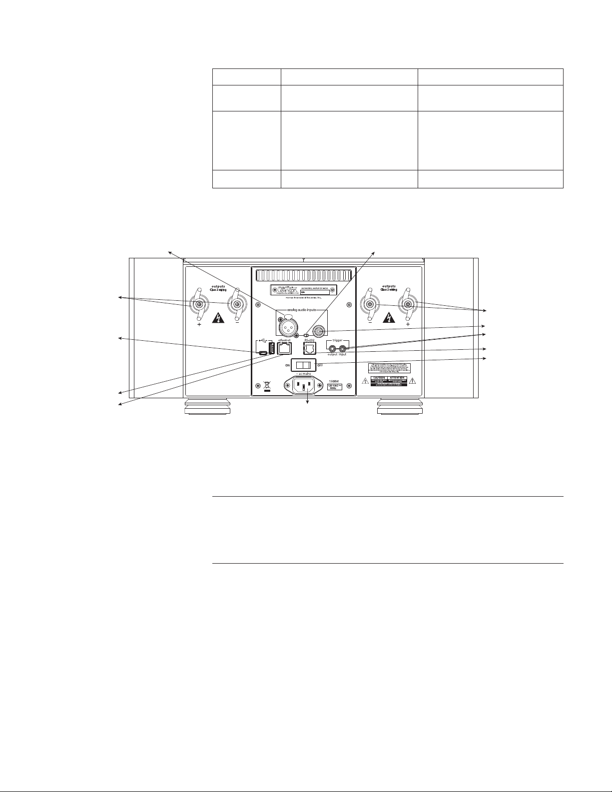
Rear Panel
Controls the AC power to the input of the amplier when a power cord is
connected from the electrical outlet to the AC input connector on the rear
panel. When the Power switch is toggled to turn on the unit, the amplier
enters Standby mode.
The audio outputs of this power amplier are considered Class 2 (CL2)
circuits in North America. This means the wire connected between this
amplier and the speaker(s) shall be rated at minimum Class 2 (CL2) and
shall be installed according to the U.S. National Electrical Code (NEC)
Article 725 or Canadian Electrical Code (CEC) Section 16.
One balanced and one single-ended (unbalanced) connector is available for
each audio channel input.
Accepts a signal from a preamplier with balanced outputs via the XLR
connector. A small toggle switch selects either the balanced (XLR) or single-
ended (RCA) input connector. Make sure the toggle switch is set to the
position closest to the XLR connector.
The pin assignments are consistent with the standards adopted by the Audio
Engineering Society. Refer to the operating manual of your preamplier
to ensure that the pin assignments of its balanced output connectors
correspond to the N
o
-536. If not, wire the cables so that the appropriate
output pin connects to the equivalent input pin.
Power Switch
Note
Audio Channel Inputs
Balanced Input
XLR balanced input
Speaker terminals with
Hurricane binding posts
Speaker terminals with
Hurricane binding posts
Trigger input and output
RCA unbalanced input
RS-232 (RJ11)
Input switch
Power switch
Micro USB
USB-A
Network (RJ45)
AC Mains
power input

Nº536 Series Power Amplifier
7
Balanced (female XLR)
Input Connector
Push
Pin 2
Pin 1
Pin 3
Pin Assignments:
Pin 1: Signal Ground
Pin 2: Signal + (non-inverting)
Pin 3: Signal - (inverting)
Connector Shell - Chassis Ground
The RCA connector accepts unbalanced or single-ended signal from
preampliers with RCA outputs. If your preamplier has both RCA and
XLR outputs, use the XLR output. Set the toggle switch to the position
closest to the RCA connector.
The N
o
-536 amplier utilizes custom-made, gold-plated, high-current
loudspeaker binding posts. The positive binding posts, labeled + (positive),
are red; the negative binding posts are black and are labeled – (negative).
Two of each binding post are present on the N
o
-536, enabling bi-wiring for
compatible loudspeakers. If your loudspeakers support bi-wiring, connect
both red (positive) terminals to the red terminals on the loudspeaker, and
connect both black (negative) terminals to the black terminals on the
loudspeaker.
If your loudspeakers do not support bi-wiring or you prefer not to employ
this connection conguration, simply connect one of the positive and one
of the negative terminals to the respective loudspeaker terminals. There is
no additional conguration needed to disable bi-wiring output capability.
Banana plugs can also be used to connect the speaker cables to the
loudspeaker binding posts. Banana plugs are not available on the
230 VAC model.
Ensure when connecting the loudspeaker that at least one positive and one
negative binding post is used. There is NO ground reference.
Be careful to not short the positive and negative outputs together.
Do not short the positive or negative outputs to chassis or any other
safety ground. The amplifier must be powered off during installation
and whenever input and/or output cables are being connected. This
is a balanced amplifier and all binding posts are active at all times.
Do not attempt to connect any binding posts to ground.
DO NOT OVERTIGHTEN the binding posts. The innovative design
of these binding posts provides more leverage; hence, high-contact,
tight pressure connections are achieved when finger-tightened.
DO NOT FORCE the binding post “wings” over a bent or oversized
connector. Doing so may damage the binding post.
Unbalanced
(Single-Ended) Input
Loudspeaker Binding
Posts
Note
Caution!
Caution!

Mark Levinson
8
Trigger Input and
Output
AC input
Caution!
Network Connection
RS-232 Connector
Operating States
Caution!
The rear panel of the amplier has two trigger connectors – one input
and one output. The trigger input can receive a 12V DC signal from a
connected component. The trigger output passes through the trigger input
signal, enabling a daisy chain of ampliers to be controlled by a single
trigger signal.
The triggers enable the power amplier to be automatically powered on
or put into Standby mode by the state of other devices in the system. The
trigger output can also affect other power ampliers in the same manner.
Receiving a trigger signal causes the amplier to change its power state.
If the amplier is powered on, then 0V on the trigger signal puts the
amplier into Standby mode. Conversely, an amplier in Standby mode is
powered on when 12VDC is received on the trigger input.
Provides AC power to the amplier when the supplied power cord is connected
from the AC Input connector on the rear panel to an electrical outlet.
Before operating the amplifier, verify that the voltage label near the
AC input connector indicates an operating voltage compatible with
the voltage level of the electrical outlet you intend to use.
The N
o
-536 connects to your network through an Ethernet cable. When
connected, the N
o
-536’s Ethernet connector’s status LED ashes.
This connector is provided to enable conguration and control of the
amplier from a personal computer equipped with a serial port. Contact
your dealer or installer for information on how to use this feature.
Operation
The amplier is designed for continuous operation and has three
operating states:
• Off – AC power is disconnected using the rear-panel Power switch or by
removing the power cord from the rear panel.
• Standby – This is an energy-saving mode with three options.
• Green (Factory Default): This is the lowest-power standby mode
for maximum energy savings. You will experience a longer power-up
process from standby. Ethernet and RS-232 are disabled in this mode.
• Power Save: Moderate energy-saving standby mode, which enables
wake-up via RS-232 or Ethernet.
• Normal: This mode mutes audio outputs, but keeps all of its control
and audio circuits powered. This mode provides the least amount of
power conservation but allows the N
o
-536’s audio circuits to remain
warmed up to deliver optimal performance at all times.
• On – The amplier is fully powered and all outputs are active.
BEFORE moving the power amplifier, make sure it is powered
off with the Power switch. Then, make sure the power cord is
disconnected from the rear panel connector and the electrical outlet.

Nº536 Series Power Amplifier
9
1. Issue these RS-232 commands:
!1062 - Set Normal Standby
!1063 - Set Green Standby
!1064 - Set PWRSave Standby
(see separate RS-232 document for additional details)
2. Issue commands via Ethernet from the N
o
-536 internal webpage.
3. Load a N
o
-536 setup le on the root of a USB ash drive connected to the
unit’s USB-A port. To load the le, power down the unit using the rear-
panel power switch, insert the drive, and turn power on.
When the N
o
-536 and a computer are both connected to the same network,
the N
o
-536 has an internal Web page that provides access to status
information and control.
Contact your dealer or installer, or see the Downloads section of the N
o
-536
webpage at marklevinson.com for instructions on how to control your
N
o
-536 from a web browser on your network.
The N
o
-536’s rmware can be updated using a USB drive connected to the
rear-panel USB-A port. With the amplier powered off using the rear-panel
Power Switch, connect the USB drive, which has the rmware update loaded
to the root of the drive. Turn the Power Switch on. The Status LED will ash
quickly, then slowly, then come to rest in Standby Mode. When the unit
reaches Standby, turn the Power Switch off and remove the USB drive.
The latest procedures can be found in the ReadMe le in the software
Downloads section of the N
o
-536 webpage at marklevinson.com.
Faults & Troubleshooting
The N
o
-
536 is designed to prevent damage to itself and associated
components. These extensive features protect both the critical circuitry of
the amplier itself and shield connected loudspeakers from serious damage
due to high power levels.
Basic protections designed into the N
o
-536 include fuses to protect against
excessive current conditions, such as driving shorted outputs. Inrush
limiting prevents premature aging of the power supply components during
power-up; once the power supply has been charged, this feature goes
ofine until the amplier is powered up again.
The N
o
-
536 actively monitors operating temperature, output current demands
and the presence of DC on the outputs. The amplier will shut down under
any of these conditions and report the fault via the front panel LED.
FAULT CONDITIONS
Recoverable faults are not caused by, nor are damaging to the amplier.
These errors either clear themselves (such as over temperature) or can be
remedied easily by the owner (speaker terminals are shorted together)
without dealer or factory intervention. These errors are:
• Amplier temperature is above safe operating limits
• Incorrect AC mains conguration
• DC detected at input
• Short or very low impedance across output terminals
To select different
standby modes:
Internal Web Page
Firmware Update
Note
Recoverable Faults

Mark Levinson
10
If you do not know how to remedy a recoverable fault condition, please
contact your retailer or installer for assistance.
Non-recoverable faults may cause damage to the amplier. These errors
indicate that the amplier likely needs service, and that the owner is
advised to call their dealer or installer for assistance. Examples of these
types of errors are:
• Left or right phase thermal switch over temperature
• Transformer over temperature
• DC detected at output (not caused by DC at the input)
• Blown fuses
• Output terminal(s) shorted to ground
• Amplier output transistors damaged
Incorrect operation is sometimes mistaken for malfunction. If problems
occur, use this section for troubleshooting information. If problems persist,
contact your authorized Mark Levinson dealer.
NO POWER
• Examine the power cord to ensure that it is connected to both the AC
mains connector and a working, unswitched electrical outlet.
• Make sure the N
o
-536 is powered on with the rear-panel Power
switch. Examine the electrical circuit breaker to ensure that power is
being supplied to the electrical outlet to which the N
o
-536 is connected.
• Make sure the N
o
-536 is not in standby. The front-panel standby LED
illuminates fully and continually when the N
o
-536 is On. The LED
ashes slowly when the N
o
-536 is in Standby mode.
NO SIGNAL AT THE SPEAKER OUTPUTS
• Examine all audio cables to ensure a solid connection between the
N
o
-536 and all associated components. Examine the speaker cables to
ensure a solid connection between the N
o
-536 and the speakers. Make
sure that the connected speakers are operational. Make sure the volume
is set to an audible level.
• Make sure all associated components are connected to working
electrical outlets and powered on. Make sure the source device
connected to the selected N
o
-536 input is producing an output signal.
Care & Maintenance
The N
o
-
536 requires routine care and maintenance to ensure optimal
performance. The bulleted items indicate maintenance procedures that should
be performed on a regular basis. Turn off the N
o
-536 and unplug the rear
AC power cord before performing maintenance to the amplifier.
Failure to perform the maintenance procedures included in this section
may void the manufacturer’s warranty and/or standard repair policies.
• To remove dust from the amplier’s exterior surface, use a feather
duster or a low-pressure blower.
Non-Recoverable
Faults
Troubleshooting
Note

Nº536 Series Power Amplifier
11
• To remove dirt and ngerprints from the amplier’s exterior surface,
use a soft, lint-free cloth. DO NOT use metal polish or a cloth made
with steel wool.
• If needed, this cloth can be dampened with isopropyl alcohol. DO
NOT dampen the cloth with Benzene, acetone-based cleaners, or other
commercial cleaners.
• Wipe the amplier’s exterior surface in the same direction as the grain
of the brushed aluminum.
DO NOT apply liquid directly to the amplifier’s exterior surface.
Doing so may damage electrical components.
Specifications
All specications are subject to change without notice.
• One balanced XLR input
• One unbalanced RCA input
• Two pairs of “Hurricane” loudspeaker outputs with banana-plug sockets
per channel (banana-plug socket not available on the 230 VAC models)
• One Ethernet 10/100 connector
• One 3.5mm mono (tip/sleeve) mini plug trigger input, 12Vdc
• One 3.5mm mono (tip/sleeve) mini plug trigger output, 12Vdc
• 3-pin IEC standard power connector
400Wrms at 8 ohms, 20Hz to 20kHz, at <0.3% THD
10Hz to 20kHz +/-0.2dB
>85dB, reference level: 2.83Vrms
60kΩ (balanced); 30kΩ (unbalanced)
26dB
2.83Vrms output at 142mVrms input
100V~, 120V~, 230V~, factory set for destination country, 1500W
Height (with feet): 7.65” (19.4cm)
Height (without feet): 6.97” (17.7cm)
Width: 17.75” (45.1cm)
Depth: 19.83” (50.4cm)
Net weight: 100lbs (45.4kg)
Shipping weight: 117lbs (53kg)
Caution!
Input & Output Connectors
Control Connectors
Rated Output Power
Frequency Response
Signal-to-Noise Ratio
Input Impedance
Voltage Gain
Input Sensitivity
Power Requirements
Dimensions
Weight

Mark Levinson
12
Declaration of Conformity
We,
Harman International Industries, Incorporated
8500 Balboa Blvd.
Northridge, CA 91329
USA
As the manufacturer and through our representative within the EU
Harman International Industries, Incorporated
EMEA Liaison Ofce, Herikerbergweg 35
1101 CN Amsterdam, The Netherlands
To declare that the product listed below
Type of Equipment: Power Amplier
Models: Mark Levinson N
o
-
536
is in conformity with the relevant Union harmonization legislation: EMC Directive 2004/108/
EC, LVD Directive 2006/95/EC, ErP Directive 2012/27/EU and RoHS Directive 2011/65/EU, if
used for its intended use and that the following harmonised standards have been applied:
1. Safety (LVD Directive 2006/95/EC)
Applied standard(s): EN 60065:2002+A1:2006+A11:2008+A2:2010+A12:2011
2. Electromagnetic compatibility (EMC Directive 2004/108/EC)
Applied standard(s): EN 55013:2001+A1:2003+A2:2006, EN 55020:2007+A11:2011,
EN 61000-3-2:2006+A1:2008+A2:2009, EN 61000-3-3:2008
3. Eco Design of Energy Related Products (ErP Directive 2012/27/EU)
Applied standard(s): (EC) No 1275/2008, (EU) No 801/2013
4. RoHS Recast Directive (RoHS Directive 2011/65/EU)
Applied standard(s): EN50581:2012
WEEE Notice
The Directive on Waste Electrical and Electronic Equipment (WEEE), which entered into
force as European law on 13th February 2003, resulted in a major change in the treatment of
electrical equipment at end-of-life.
The purpose of this Directive is, as a rst priority, the prevention of WEEE, and in addition, to
promote the reuse, recycling and other forms of recovery of such wastes so as to reduce disposal.
The WEEE logo on the product or on its box indicating collection for electrical and electronic
equipment consists of the crossed-out wheeled bin, as shown below.
This product must not be disposed of or dumped with your other household waste. You are
liable to dispose of all your electronic or electrical waste equipment by relocating over to
the specied collection point for recycling of such hazardous waste. Isolated collection and
proper recovery of your electronic and electrical waste equipment at the time of disposal will
allow us to help conserving natural resources. Moreover, proper recycling of the electronic
and electrical waste equipment will ensure safety of human health and environment. For
more information about electronic and electrical waste equipment disposal, recovery, and
collection points, please contact your local city center, household waste disposal service, shop
from where you purchased the equipment, or manufacturer of the equipment.
RoHS Compliance
This product is in compliance with Directive 2011/65/EU of the European Parliament and of
the Council of 8 June 2011 on the restriction of the use of certain hazardous substances in
electrical and electronic equipment.
Harman International hereby declares that this equipment is in compliance with the EMC
2004/108/EC Directive, LVD 2006/95/EC Directive, ErP 2012/27/EU/EC Directive and RoHS
2011/65/EU Directive. The declaration of conformity may be consulted in the support section
of our website, marklevinson.com.