Table of Contents
3
EN
1Installation 9
1.1 General installation instructions 9
1.2 Electrical requirements 10
1.3 Electrical connection 11
1.4 Positioning 15
1.5 Cutting out the countertop 16
1.6 Recess 19
Important Notes to the Installer
• Read all instructions contained in these installation instructions before
installing the cooktop.
• Remove all packing material from the oven and the drawer compartments
before connecting the electrical supply to the cooktop.
• Observe all governing codes and ordinances. Be sure to leave these
instructions with the consumer.
Important Note to the Customer
• Keep these instructions with your owner's guide for future reference.
Definitions
• This manual contains important safety symbols and instructions.
• Please pay attention to these symbols and follow all instructions given.
IMPORTANT SAFETY INSTRUCTIONS
WARNING
If the instructions contained in this manual are not followed
correctly, fire or explosion may result causing property
damage, personal injury or loss of life.
INSTALLATION AND SERVICE MUST BE PERFORMED BY A
QUALIFIED INSTALLER.
IMPORTANT: SAVE FOR THE LOCAL INSPECTOR’S USE.
Important Safety Instructions
4
Appliance Handling Safety
Hidden surfaces may have sharp
edges. Use caution when reaching
behind or under the appliance.
• Wear gloves to avoid cutting
fingers on sharp edges during
installation.
The unit is heavy and requires at least
two persons or proper equipment to
move it.
Safety Codes and Standards
This appliance complies with one or
more of the following Standards:
UL 858 - The Standard for the
Safety of Household Electric
Ranges
CAN/CSA-C22.2 No. 61
Household Cooking Ranges
• It is the responsibility of the owner
and the installer to determine
whether additional requirements
and/or standards apply to
specific installations.
• The appliance must be electrically
grounded in accordance with
local codes or, in the absence of
local codes, with the National
Electrical Code, NFPA 70 latest
edition or, in Canada, the
Canadian Electric Code, CSA
C22.1-02.
• Do not store items of interest to
children in the cabinets above the
cooktop. Children could be
seriously burned if they climb on
the cooktop to reach items.
WARNING
This symbol will help alert you to
situations that may cause serious bodily
harm, death or property damage.
CAUTION
This symbol will help alert you to
situations that may cause injury or
property damage.
WARNING
Never leave children alone or
unattended in the area where an
appliance is in use. As children grow,
teach them the proper and safe use of all
appliances.
CAUTION
Stepping, leaning, or sitting on this
cooktop can result in serious injuries and
can also cause damage to the cooktop.
Important Safety Instructions
EN
5
• Do not store or use gasoline or
other flammable vapors and
liquids near this or any other
appliance. Explosions or fires
could result.
Electric Safety
• Personal injury or death from
electrical shock may occur if the
appliance is not installed by a
qualified installer or electrician.
• Make sure your appliance is
properly installed and grounded
by a qualified electrician.
Installation, electrical connections
and grounding must comply with
all applicable codes.
• Before installing, turn power OFF
at the service panel. Lock the
service panel to prevent power
from being turned ON
accidentally.
• For appliances equipped with a
cord and plug, do not cut or
remove the ground prong. It must
be plugged into a matching
grounding type outlet to avoid
electrical shock. If there is any
doubt as to whether the wall
outlet is properly grounded, the
customer should have it checked
by a qualified electrician.
• Do not use an extension cord.
• Do not use an adapter.
• If required by the National
Electrical Code (or Canadian
Electrical Code), this appliance
must be installed on a separate
branch circuit.
• The circuit breaker should have a
contact separation of at least
3 mm on all poles.
• INSTALLER – show the owner the
location of the circuit breaker or
fuse. Mark it for easy reference.
• Refer to rating label for more
information.
WARNING
Do not repair, replace or remove any
part of the appliance unless specifically
recommended in the manuals. Improper
installation, service or maintenance can
cause injury or property damage. Refer
to this manual for guidance. All other
servicing should be done by an
authorized service provider.
WARNING
Before you plug the electrical cord into
an outlet, make sure that all the
appliance controls are in the OFF
position.
Important Safety Instructions
6
Proposition 65 Warning:
This product may contain a chemical known
to the State of California, which can cause
cancer or reproductive harm. Therefore, the
packaging of your product may bear the
following label as required by California:
Related Equipment Safety
• The appliance should only be
used if installed by a qualified
technician in accordance with
these installation instructions and
all applicable regulations and
codes. The manufacturer is not
responsible for damages resulting
from incorrect installation.
• Remove all tape and packaging
before using the appliance.
Dispose of the packaging after
unpacking the appliance. Never
allow children to play with
packaging material.
• Never modify or alter the
construction of the appliance.
• To eliminate the risk of burns or fire
by reaching over hot surface
units, cabinet storage space
located above the surface units
should be avoided. If cabinet
storage is to be provided, the risk
can be reduced by installing a
hood that projects horizontally a
minimum of 5 inches (127 mm)
beyond the bottom of the cabinet.
Be sure cabinets above the
cooktop are a maximum of 13 in
(330 mm) deep.
• When installing a cooktop over a
single oven, be sure to follow
both the oven and cooktop
installation manuals.
Ventilation Recommendations
• Do not obstruct air vents or heat
vent openings.
• We strongly recommend the
installation of a ventilation hood
above this appliance. The hood
must be installed according to the
instructions provided with the
hood.
State of California Proposition 65
WARNING
Cancer or Reproductive Harm -
www.P65Warnings.ca.gov
Important Safety Instructions
EN
7
High-altitude installation
• This appliance can operate up to
an altitude of 10,000 ft (3048 m)
elevation above sea level. If
desired, for altitudes above
2,000 ft (610 m) elevation above
sea level, adjustments may be
made.
• It is required that a Certified
Professional make the high
altitude adjustments during
installation.
• Improper installation is not
covered by the warranty.
• Read all instructions
• Proper installation is your responsibility.
Have a qualified technician install and
ground this appliance in accordance
with these installation instructions.
• It is the responsibility of the installer to
comply with installation information
specified on the model/serial ID plate.
The ID plates are visibly located under
the appliance. These ID plates must
never be removed.
• ELECTRICAL GROUNDING IS
REQUIRED: See the “Electrical
Requirements” section. It is the customer’s
responsibility to:
• Contact a qualified electrician to install
the appliance
• Ensure that the electrical system is
adequate and in compliance with the
National ANSI / NFPA 70 ELECTRICAL
CODE – latest edition – Or the
CANADIAN ELECTRICAL CODE,
C22.11 – 1 and C22.2 No. 01982 –
or latest edition – and all local codes
and ordinances. IMPORTANT: Observe
all governing codes and ordinances.
• Never modify or alter the construction of
the appliance. For example, do not
remove adjustable legs, panels, wiring
or anti-tip brackets/screws.
• Do not obstruct heat vents or openings
on the appliance.
• Test the appliance immediately after
installation, following the instructions in
this booklet. If the appliance does not
work properly, disconnect it from the
electrical power supply and call the
Customer Service Center. DO NOT
attempt to repair the appliance.
WARNING
If the information in this manual is not
followed exactly, fire or shock may result
causing property damage or personal
injury.
CAUTION: This unit is designed as
a cooking appliance. For safety
purposes, never use it for warming
a room or as a space heater.
Important Safety Instructions
8
• All adjustments and servicing must be
performed by qualified installers or
service technicians.
• Do not leave the packing materials
around the home. Sort the various items
of waste and take them to the nearest
specialized waste collection facility.
• Do not store or use gasoline or other
flammable vapors, liquids or materials
near this or any other appliance.
How to read the user manual
This user manual uses the following reading
conventions:
1. Order of use instructions.
• Stand-alone instructions.
SAVE THESE INSTRUCTIONS
Instructions
General information on this user
manual, on safety, and on final
disposal.
Description
Description of the appliance and its
accessories.
Use
Information on the use of the
appliance and its accessories,
cooking advice.
Cleaning and maintenance
Information for proper cleaning and
maintenance of the appliance.
Safety instructions
Information
Installation
9
EN
1 Installation
1.1 General installation instructions
• Proper installation is your
responsibility. Have a qualified
technician install this appliance. Make
sure you have everything necessary for
correct installation. It is the responsibility
of the installer to comply with installation
guidelines indicated on the model/serial
ID plate. The model/serial ID can be
found under the appliance.
• Have your appliance installed and
properly grounded by a qualified
installer, in accordance with these
installation instructions. Grounding is
mandatory according to the provisions of
the electrical system safety regulations. If
this appliance is connected to an outside
electrical power source, it must be
grounded in compliance with local laws,
or, if no local laws exist, in compliance
with the national ANSI/NFPA 70 code
of electrical regulations.
• Make sure that the voltage and
dimensions of the supply line correspond
to the information indicated on the
model/serial rating plate. A multi-pole
circuit breaker must be available on the
supply line with contact gap equal to or
greater than 3mm, located in an easily
accessible position near the appliance.
• Do not attempt to repair or replace any
part of the appliance unless specifically
recommended in this manual. All other
service procedures should be performed
by a qualified technician.
• This appliance is not suitable for
installation and use in mobile homes or
campers.
• Electrical grounding is required. See
the “Electrical requirements” section. It is
the customer’s responsibility to:
1. Contact a qualified electrical installer.
2. Ensure that the electrical system is
adequate and in compliance with the
National ANSI / NFPA 70 ELECTRICAL
CODE – latest edition – Or the
CANADIAN ELECTRICAL CODE,
C22.11 – 1982 and C22.2 No.
01982 - or latest edition - and all local
codes and ordinances.
IMPORTANT: Observe all codes and
ordinances in force.
In case of multiple installations,
cooktops cannot be installed
adjacent to each other.

Installation
10
1.2 Electrical requirements
Make sure that the power line rating
matches the specifications indicated on the
ID plate. The ID plates are visibly located
under the appliance.
These ID plates must never be removed.
• If codes permit and a separate ground
wire is used, it is recommended that a
qualified electrician check the suitability
of the ground path.
• Wire size and connections must conform
to the requirements of the National
Electrical Code, ANSI/NFPA 70
ELECTRICAL CODE (*) – latest edition
or CSA Standard C22.1-94, Canadian
Electrical code, Part 1 (**) and CSA
C22.2 No. O-91 or latest edition and
all local codes and ordinances for the
kilowatt rating of the appliance.
IMPORTANT: Observe all governing
codes and ordinances.
• Copies of the standards listed above
may be obtained from:
• (*) National Fire Protection Association,
One Batterymarch Park, Quincy,
Massachusetts 02169-7471
• (**) CSA International 8501 East
Pleasant Valley Road Cleveland, Ohio
44131-5575.
Warning
Electrical shock hazard
• Have the electrical connection
performed by authorized technical
personnel.
• The frame is grounded by connecting
the grounding lead to the neutral lead. If
local codes do not permit grounding
through the neutral lead, open the
connection and use the grounding lead
to ground the unit in accordance with
local codes. Connect the neutral lead to
the branch-circuit neutral conductor in
the usual manner.
• Do not use an adapter.
• Do not use an extension cord.
• Check with a qualified electrician if you
are not sure whether the appliance is
grounded.
• Turn the power supply off before
connecting the wires.
• Ground the appliance electrically.
• Failure to follow these instructions can
result in death, fire, or electrical shock.
• Improperly connecting the appliance’s
grounding conductor can result in
electrical shock. Check with a qualified
electrician or service technician if you
are in doubt as to whether the appliance
is properly grounded. Do not modify the
power supply cord. If it does not fit in the
outlet, have a proper outlet installed by
a qualified electrician.
• Disconnect the main power supply.
FAILURE TO FOLLOW THESE
INSTRUCTIONS COULD
RESULT IN DEATH, FIRE OR
ELECTRICAL SHOCK.
Installation
11
EN
1.3 Electrical connection
This appliance is manufactured with a
green or green-yellow ground wire
connected to the frame of the appliance.
To prepare the connection between the
appliance and the junction box:
• Disconnect the power supply to the
junction box.
• Feed the flexible cable conduit from the
appliance through the opening of the
cabinet.
• Remove the junction box cover, if
present.
• Install a UL-listed or CSA-approved
conduit connector to the junction box.
• Route the flexible cable conduit from the
appliance to the junction box through a
UL-listed or CSA-approved conduit
connector.
• Tighten the screws on the conduit
connector.
IMPORTANT: Any local codes or
ordinances should be given priority over
these instructions.
The frame is grounded by connecting the
grounding wire to the neutral wire. If the
new branch circuit installation (1996 NEC)
is used or if local codes do not permit
grounding through the neutral wire, open
the connection and use the grounding wire
to ground the unit in compliance with local
codes. Connect the neutral wire to the
branch circuit’s neutral conductor in the
usual manner:
• Disconnect the ground from the neutral
at the free end of the conduit.
• Use the grounding terminal or lead to
ground the unit.
• Connect the neutral terminal or wire to
the branch circuit neutral in the usual
manner.
• This range is equipped with a factory
connected power cord. The cord must
be connected to a grounded 120/240
volt or 120/208 volt outlet. If no outlet is
available, have one installed by a
qualified electrician.
Warning
Electrical shock hazard
• Disconnect power to the junction box
before connecting.
• Electrically ground the appliance using
the green or green-yellow wire.
FAILURE TO FOLLOW THESE
INSTRUCTIONS COULD
RESULT IN DEATH, FIRE OR
ELECTRICAL SHOCK.
Installation
12
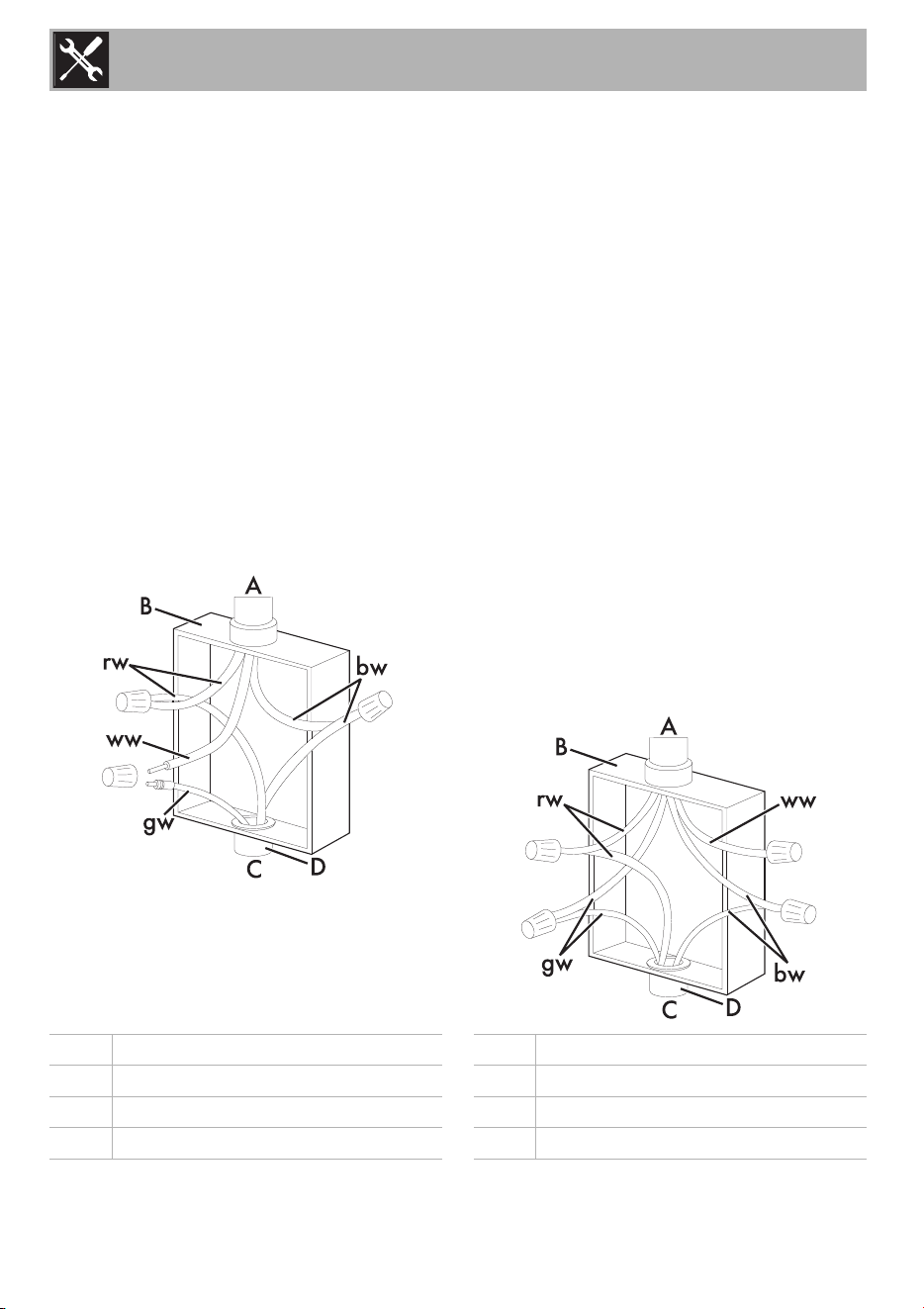
U.S. Installation only / 3-wire branch
circuit
Refer to figure, where local codes allow the
connection of the ground wire from the
oven to the power supply cable neutral
wire (white wire):
• The ground wire must be connected first;
• If local codes permit, connect the green
or yellow-green ground wire from the
range and the white wire from the range
to the power supply neutral wire (white
wire).
• Connect the red and black leads from
the range to the matching color wires in
the junction box using UL/CSA listed
wire connectors.
U.S. and Canada installation / 4-wire
branch circuit
• Separate the green or yellow-green
wires from the white wires that extend out
of the end of the appliance cable.
• The ground wire must be connected first.
• Connect the green or yellow-green
ground wire from the appliance to the
ground wire in the junction box (green
colored wire) using UL/CSA listed wire
connectors. Do not connect the
grounding wire to the neutral wire in the
junction box.
• Connect the red and black leads from
the appliance to the matching color
wires in the junction box using UL/CSA
listed wire connectors.
• Connect the white wire from the
appliance to the neutral white wire in the
junction box using a UL/CSA listed wire
connector.
A cable from power supply bw black wires
B junction box gw white-green or yellow-green wires
C cable from range rw red wires
D UL/CSA listed conduit connector ww white wires
Installation
13
EN
• Connect to a 40A fuse or circuit breaker.
Connect to copper wire, or, if
connection is made to aluminum house
wiring, use UL-listed or CSA-approved
connectors approved for joining
aluminum and copper wiring.
Fixed connection
Fit the power line with a multi-pole circuit
breaker in compliance with installation
regulations.
The circuit breaker should be located near
the appliance and in an easily reachable
position.
Instructions for the installer
• Do not bend or trap the power supply
cord.
• The appliance must be installed
according to the installation diagrams.
• If the appliance does not work correctly
after having carried out all the checks,
contact your local Authorized Service
Center.
• Once the appliance has been installed,
please explain to the user how to use it
correctly.
Power limitation procedure
(for installer only)
To modify the maximum power input of the
appliance, it is necessary to access the user
menu.
Accessing the user menu
1. If the cooktop is off, switch it on using the
On/Off button .
2. Then press the On/Off button again
immediately to switch it off: the pause
button starts to flash.
3. Press and hold the pause button .
Some symbols will appear on the
cooking zone displays that must be
pressed in sequence in order to access
the menu options.
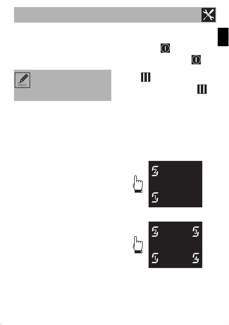
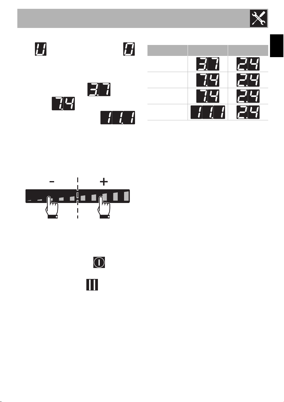
Press all the buttons of the cooking zones in
sequence in a clockwise direction starting
from the front left. Every effective touch will
be confirmed by a beep.
15 in - 380 mm model:
24 in - 610 mm and 30 in - 762 mm
models:
NOTE: Both leads coming out of
the range must be connected
according to the diagrams shown
in figures.
Installation
14
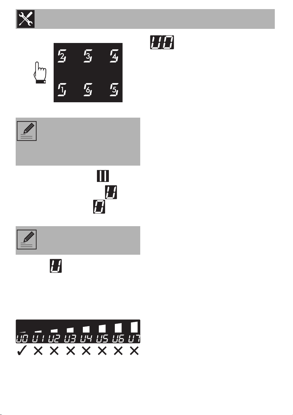
36 in - 914 mm model:
4. Release the pause button .
The user menu is active and the symbol
alternating with the number will appear
at the top of the cooking zones display.
5. Press the symbol to go back to
selecting the options. The scroll bar
appears in which each segment is
associated with a menu option.
Press the segments of the scroll bar (except
the first two) to select the available options.
Once the user menu has been accessed,
the first available option is indicated by
(Maximum total power). A total of
7 options can be modified.
NOTES: If the sequence of the
buttons is selected incorrectly, the
cooktop will be turned off and the
procedure for accessing the menu
will have to be repeated.
NOTES: This option is restricted to
the installer.
Installation
15
EN
1. Once the user menu has been accessed,
the symbol alternating with the
symbol will appear at the top of the
cooking zone display.
2. The timer display on the other hand, indicates
the default power setting (15 in -
380 mm), (24 in - 610 mm and
30 in - 762 mm models) and
(36 in - 914 mm model).
3. Press the timer display to enable changes
to the power settings.
4. Press the left side of the scroll bar to
decrease the power and the right side to
increase it.
The Eco-Logic Advance function increases
or decreases the power level in steps of
0.1 kW at each touch.
To exit from the user menu:
1. Press the On/Off button for at least
2 seconds to save the modifications.
2. Press the pause button to exit without
saving the modifications.
In both cases, the cooktop will be switched
off and will have to be turned back on.
Power draw table (kW)
Model Max. min.
15 in - 380 mm
24 in - 610 mm
30 in - 762 mm
36 in - 914 mm
Installation
16
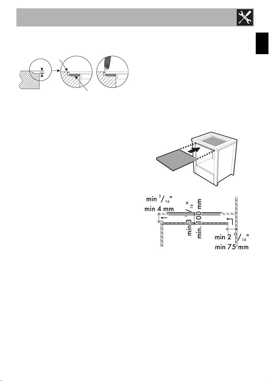
1.4 Positioning
Veneers, adhesives or plastic coatings on
adjacent units should be heat-resistant
(>90°C), otherwise they might warp over
time.
The minimum clearance between extractor
hoods and the cooking surface must be at
least the distance indicated in the extractor
hood installation instructions.
The minimum clearances of the cutouts for
the cooktop on the back side as shown in
the mounting illustrations must also be
observed.
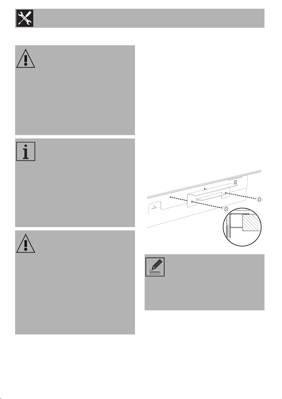
Spacer bracket
• Screw the spacer brackets onto the sides
of the appliance.
Increasing heat when the
appliance is in operation
Risk of fire
• Check that the surrounding cabinetry
material is heat-resistant.
• Check that the cabinetry has the
required openings.
• Do not obstruct the ventilation grille in
front of the product during installation.
The following requires building
and/or carpentry work, which
must be carried out by a
competent technician.
The appliance may be installed on
various materials such as masonry,
metal, solid wood and plastic
laminated wood, provided they
are heat resistant (>90°C -
194°F).
Warning
Electrical shock hazard
• To eliminate the risk of burns or fire by
reaching over hot surface units, cabinet
storage space located above the
surface units should be avoided. If
cabinet storage is to be provided, the
risk can be reduced by installing a
cooktop hood that projects horizontally
a minimum of 5 inches beyond the
bottom of the cabinets.
Refer to the side spacer brackets
for correct installation.
The side spacer brackets should
never be removed. Their removal is
considered as tampering with the
device.
Installation
17
EN
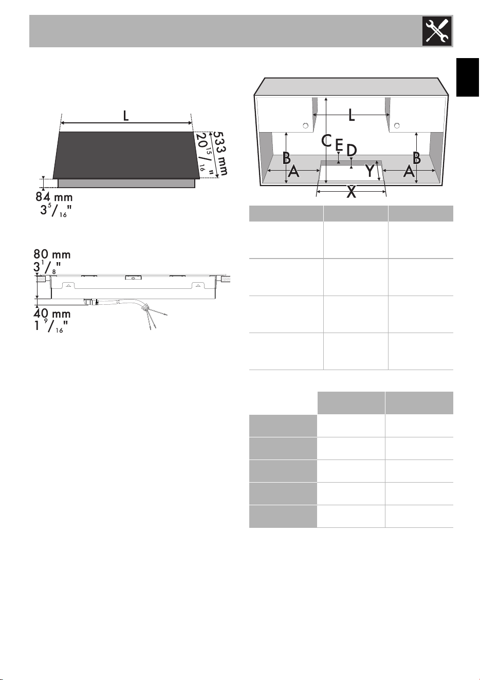
1.5 Cutting out the countertop
Cut an opening in the countertop of the unit
according to the dimensions shown (mm).
rear view
Semi-flush mounting
C = 30” - 762 mm minimum clearance
between the top of the cooking surface and
the bottom of an unprotected wood or
metal cabinet.
L X Y
15 in - 380 mm
12
9
/
16
”
19
5
/
16
”
320 mm 490 mm
24 in - 610 mm
22
13
/
16
” 19
5
/
16
”
580 mm 490 mm
30 in - 762 mm
29
5
/
16
”
19
5
/
16
”
745 mm 490 mm
36 in - 914 mm
34
5
/
8
”
19
5
/
16
”
880 mm 490 mm
inches mm
A min.
1
15
/
16
”
50
B min.
18
1
/
8
”
460
C min.
30” 762
D
3
/
4
÷ 2
3
/
8
20 ÷ 60
E min.
1
15
/
16
”
50
Installation
18
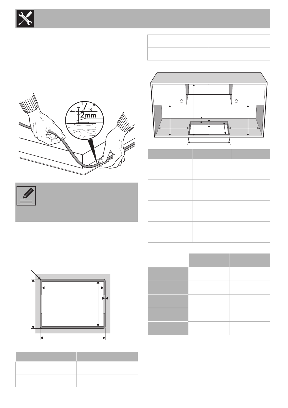
Seal the cooktop
Before assembly, to prevent leakage of
liquid between the frame of the cooktop
and the countertop, place the provided
adhesive seal along the entire perimeter of
the cooktop.
Flush mounting
This type of cooktop requires an additional
cut to be made in the recess if you wish to
install the hob flush with the countertop.
Once the adhesive seal (A) has been
applied to the glass surface and the
cooktop has been positioned and clamped
in place, fill the edges with insulating
silicone (B) and remove any excess. If for
any reason the cooktop needs to be
Do not attach the cooktop with
silicone. It will prevent the cooktop
from being removed when
necessary without damage.
G H
15
1
/
8
” - 384 mm 21
1
/
8
” - 537 mm
24
3
/
16
” - 614 mm 21
1
/
8
” - 537 mm
GG
R5
H
5 mm
"/
3
16
"
XX
YY
30
3
/
16
” - 766 mm 21
1
/
8
” - 537 mm
36
1
/
8
” - 918 mm 21
1
/
8
” - 537 mm
L X Y
15 in - 380 mm
12
9
/
16
”
320 mm
19
5
/
16
”
490 mm
24 in - 610 mm
22
13
/
16
”
580 mm
19
5
/
16
”
490 mm
30 in - 762 mm
29
5
/
16
”
745 mm
19
5
/
16
”
490 mm
36 in - 914 mm
34
5
/
8
”
880 mm
19
5
/
16
”
490 mm
inches mm
A min.
1
15
/
16
”
50
B min.
18
1
/
8
”
460
C min.
30” 762
D
3
/
4
÷ 2
3
/
8
20 ÷ 60
E min.
1
15
/
16
”
50
X
CC
EE
DD
YY
AA
BB
AA
BB
LL
Installation
19
EN
removed, cut the silicone with a cutter
before attempting to remove it (C).
1.6 Recess
On a hollow compartment or drawer
If there are other furniture parts (side panels,
drawers, etc.), dishwashers or refrigerators,
under the cooktop, a double-layer wooden
base must be installed at a minimum
distance of 51 mm (2 in) from the
underside of the cooktop to prevent
accidental contact. The double-layer base
must be removed using only the
appropriate tools.
with opening on the base
1mm1mm
AA
5 mm5 mm
BB
CC
3
/"
16
3
/"
16
1
/"
16
1
/"
16
Installation
20
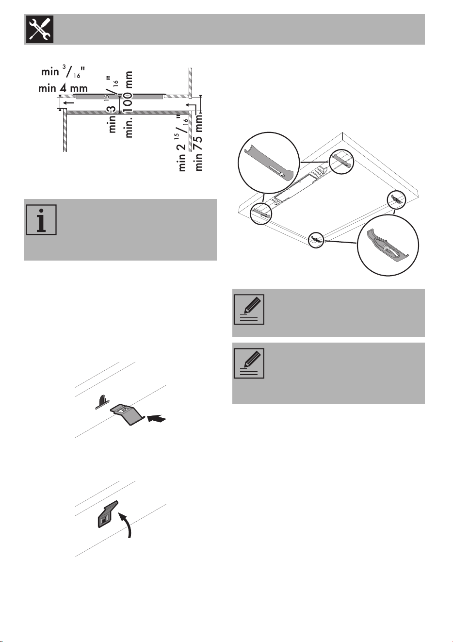
with opening on the back
Fastening clips
To ensure the attachment and optimal
centering, you should use the supplied clips:
1. Insert the clips and fix them in place
horizontally into the groove with light
pressure.
2. Rotate them upwards to fix them in place
permanently.
Fixing brackets
• Screw the fixing brackets into the holes
on the lower sides of the casing to
properly secure the cooktop to the
structure.
Failure to install the double-layer
wooden base exposes the user to
possible accidental contact with
sharp or hot surfaces.
Fixing the cooktop too tightly may
strain the glass and cause it to
break.
Do not use silicone to secure the
cooktop. Doing so would make it
impossible to remove the cooktop
without damage.