Page 1 of 4
For assistance, please contact Stinger at gmsuppor[email protected] or call (866) 766-2267
Tools Required:
7mm Nut Driver or Socket with Ratchet
8mm Nut Driver or Socket with Ratchet
10mm Nut Driver or Socket with Ratchet
Plastic dash panel removal tool
Drill with Phillips bit
Alcohol Pads.
Stinger OPSIS Dash Cam Installation Sheet
Read and understand these instructions rst before proceeding with the installation of the OPSIS Dash Cam.
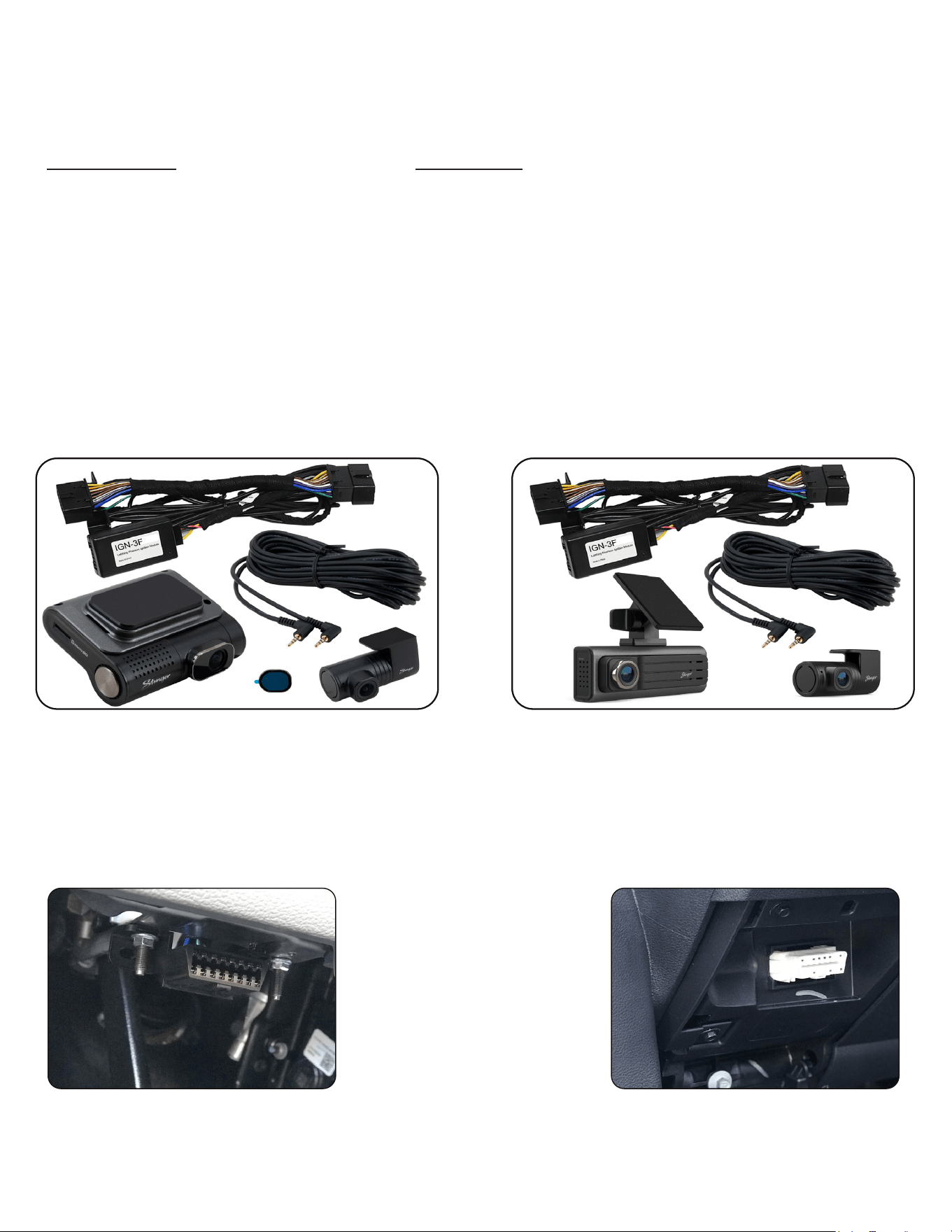
Kit Contents:
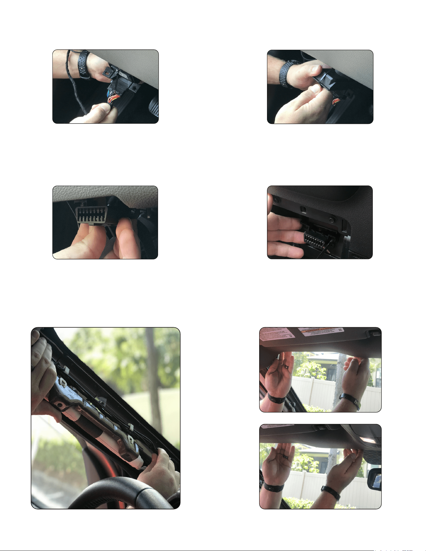
1. Locate the OBD II connector
in the vehicle and release it from
the mounting surface. This may
require the removal of two 7 or
8mm nuts from the studs securing
it to the under dash (Fig. A) or by
depressing the two side clips, with
a plastic dash trim tool, securing it
behind the drop down plastic cover
(Fig. B).
Fig. A
Fig. B
1. HWK-TW01-HAR - OBD II Plug-n-Play Dash Camera Harness
2. Forward Facing Camera
3. Rear facing camera
4. Connection cable from front to rear camera
5. IGN-3F Ignition Module
6. Windshield mount for front facing camera
7. CPL-Filter (19540255 only)
8. Micro SD memory card (pre-installed in unit)
9. 2 x 14” Wire Ties
10. 2 x #8 Self Tapping Stinger Head Screws
1954025419540255
Page 2 of 4
For assistance, please contact Stinger at gmsuppor[email protected] or call (866) 766-2267
2. Connect the male end of the included Plug-n-Play HWK-
TW01-HAR to the vehicle’s factory ODB II connector (Fig. A).
3. Secure the OBD II connector and the harness together
using one of the included wire ties and cut o any excess wire
tie that is not needed (Fig. B).
4. For the Nut and Bolt style mounting system: Place the left ear of the connector over the left factory stud and replace and tighten
the 8mm nut removed in step 1. Secure the right ear of the connector to the under dash using the included self tapping screw (Fig.
C).
For the clip in style mounting system: Feed the body of the harness into the dash opening and secure connector to the dash using
the included self tapping screws (Fig. D).
Fig. A Fig. B
Fig. DFig. C
5. Remove the A-Pillar trim panel; this may require the removal of 2 x 10mm bolts. Route the OPSIS power cable over to the driver
side of the vehicle, up the A-Pillar (Fig. E) and across the front of the headliner (Fig. F & G) so that it exits the headliner at the
factory notch above the rearview mirror. NOTE: When routing cables near the side curtain airbag, be sure to route them in a
way that will not impact the airbags’ ability to deploy in the event of an accident.
Fig. E
Fig. F
Fig. G
Page 3 of 4
For assistance, please contact Stinger at gmsuppor[email protected] or call (866) 766-2267
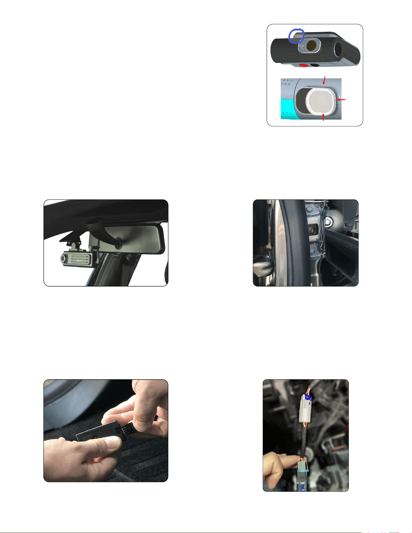
7. Clean and dry the mounting location with an alcohol pad prior to mounting camera. Slide the camera into the mount and
secure it to the windshield using the pre-installed adhesive pad on the mount (Fig. A). It is recommended to mount the dash
cam behind the rear view mirror in a manner to not obstruct the view of the driver while positioning the camera lens as close
to the center of the vehicle and as level as possible. Connecting to the dash cam using the OPSIS smartphone app may be
necessary to ne tune the up and down adjustment so that the picture is adequate. Once the camera has been mounted be
sure to bundle and secure all left over cable (Fig. B).
Fig. A
6. FOR 19540255 ONLY: Installing the CPL Filter
The CPL Filter will reduce windshield reection and glare,
improving the overall image quality.
a. Clean the lens and surrounding area of your dash cam.
b. Remove the blue tinted clear adhesive backing.
c. For proper placement, align the three edges of the lter with
the camera window and secure it in place. NOTE: This is semi-
permanent and not meant to be removed.
d. Remove the clear protective lm
Fig. B
8a. With the vehicle’s ignition in the OFF position, connect
the IGN-3F to the 10-Pin Molex connector located on the
HWK-TW01-HAR (Fig. C).
Fig. C
For vehicles with combustion engines ONLY. For vehicles with electric motors ONLY.
8b. Locate the closest switched power Accessory
Power Receptacle (Cig Plug) and gain access to the
harness on the back side. Connect the provided power
receptacle “T” harness in-line with the factory harness
and the receptacle (Fig. D). Route the 10 pin Molex side
of the “T” harness to the OBDII area and connect it to
the mating 10 Pin Molex connector installed previously.
Fig. D
Page 4 of 4
For assistance, please contact Stinger at gmsuppor[email protected] or call (866) 766-2267
These next steps are only needed when installing the rear facing camera.
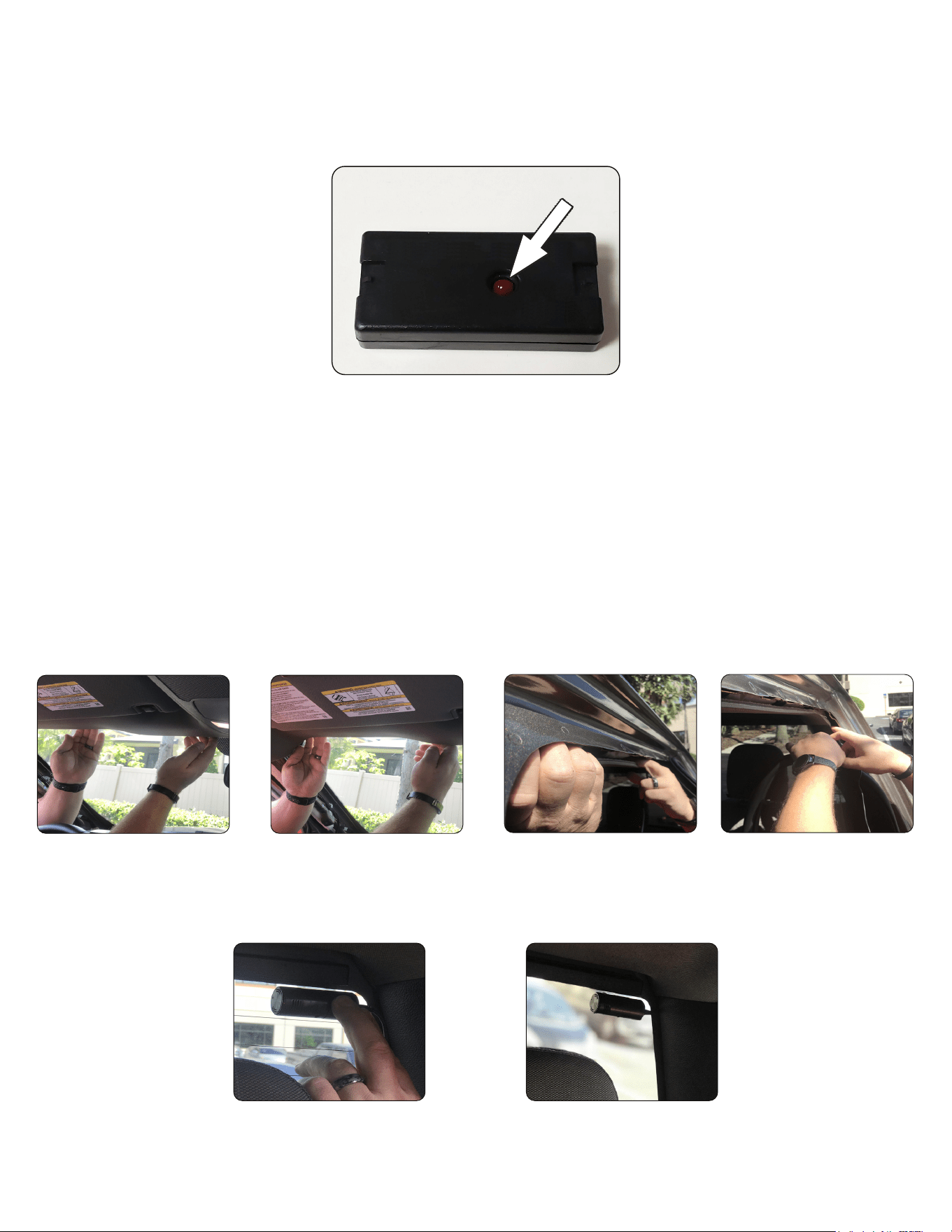
12. Using the techniques mentioned earlier, tuck and route the cable in the headliner from the front camera to the mounting
position of the rear camera. See Fig. A - D for clarication. NOTE: When routing cables near the side curtain airbag, be
sure to route them in a way that will not impact the airbags’ ability to deploy in the event of an accident.
Fig. A Fig. B Fig. C Fig. D
13. Clean and dry mounting location with an alcohol pad prior to mounting camera. Mount the camera on the rear window using
the supplied adhesive on the camera. Keep in mind to not mount camera in a location that will interfere with rear view mirror
visibility. Connecting to the dash cam using the Stinger OPSIS smartphone app may be necessary to verify that the picture is
right side up and the entire rear of vehicle is in the frame. See Fig. E and F for clarication.
Fig. E Fig. F
14. Ensure that any and all of the vehicle’s trim that may have been removed during the previous installation steps is
reinstalled.
9. With the vehicle’s ignition in the OFF position and the IGN-3F plugged in, the LED should be emitting a slow consistent ash.
The LED will change from a ashing state to being ON solid once you start the vehicle. When the LED is ON solid, a phantom
ignition signal will be sent to the dash cam to turn it on and will remain on during the event of a start/stop sequence. The LED and
dash cam will turn o 2 minutes and 30 seconds after the vehicle is shut down.
10. Using the included wire tie, secure the module and the factory OBD II junction under the dash or kick panel in a way that will
not impact the airbags’ ability to deploy in the event of an accident.
11. Ensure that any and all of the vehicle’s trim that may have been removed during the previous installation steps is reinstalled.
Steps 9 & 10 are for vehicles with combustion engines only.