Wireless Monitoring Solutions
Product Manual
IZON
®
LRT-4000 Series
Long Range Wireless Transmitter
126-1039 © Icon Process Controls Ltd.

Contents
1. Warnings ...................................................................................................................................................................................................................................................................................................3
2. Product Introduction ....................................................................................................................................................................................................................................................................4
3. Description ............................................................................................................................................................................................................................................................................................4
4. Specications .......................................................................................................................................................................................................................................................................................5
5. Main Port M12 Pin Assignment ..............................................................................................................................................................................................................................................5
6. Wiring – Flying Lead ...................................................................................................................................................................................................................................................................... 6
7. LED Indicator .......................................................................................................................................................................................................................................................................................6
8. Dimensions (mm) ............................................................................................................................................................................................................................................................................ 7
9. Installation..............................................................................................................................................................................................................................................................................................8
10. Communication .............................................................................................................................................................................................................................................................................. 9
IZON
®
LRT-4000 Series
Long Range Wireless Transmitter
226-1039 © Icon Process Controls Ltd.

This equipment has been tested and found to comply with the limits for a Class B digital device, pursuant to Part 15 of
the FCC Rules. These limits are designed to provide reasonable protection against harmful interference in a residential
installation.
This equipment generates, uses and can radiate radio frequency energy and, if not installed and used in accordance
with the instructions, may cause harmful interference to radio communications. However, there is no guarantee that
interference will not occur in a particular installation. If this equipment does cause harmful interference to radio or
television reception, which can be determined by turning the equipment off and on, the user is encouraged to try to
correct the interference by one of the following measures:
? Reorient or relocate the receiving antenna.
? Increase the separation between the equipment and receiver.
? Connect the equipment into an outlet on a circuit different from that to which the receiver is connected.
? Consult the dealer or an experienced radio/TV technician for help.
To assure continued compliance, any changes or modications not expressly approved by the party responsible for
compliance could void the user’s authority to operate this equipment. (Example - use only shielded interface cables when
connecting to computer or peripheral devices).
? This equipment complies with FCC RF radiation exposure limits set forth for an uncontrolled environment. This
equipment should be installed and operated with a minimum distance of 20 centimeters between the radiator and
your body.
? This transmitter must not be co-located or operating in conjunction with any other antenna or transmitter.
? The antennas used for this transmitter must be installed to provide a separation distance of at least 20 cm from all
persons and must not be co-located or operating in conjunction with any other antenna or transmitter.
This device complies with Part 15 of the FCC Rules. Operation is subject to the following two conditions:
(1) This device may not cause harmful interference, and
(2) This device must accept any interference received, including interference that may cause undesired operation.
Federal Communication Commission Interference Statement
1. Warnings
FCC Caution
FCC Radiation Exposure Statement
Note:
FCC ID : 2BUXBLRT-4000
WARNING
IZON
®
LRT-4000 Series
Long Range Wireless Transmitter
326-1039 © Icon Process Controls Ltd.
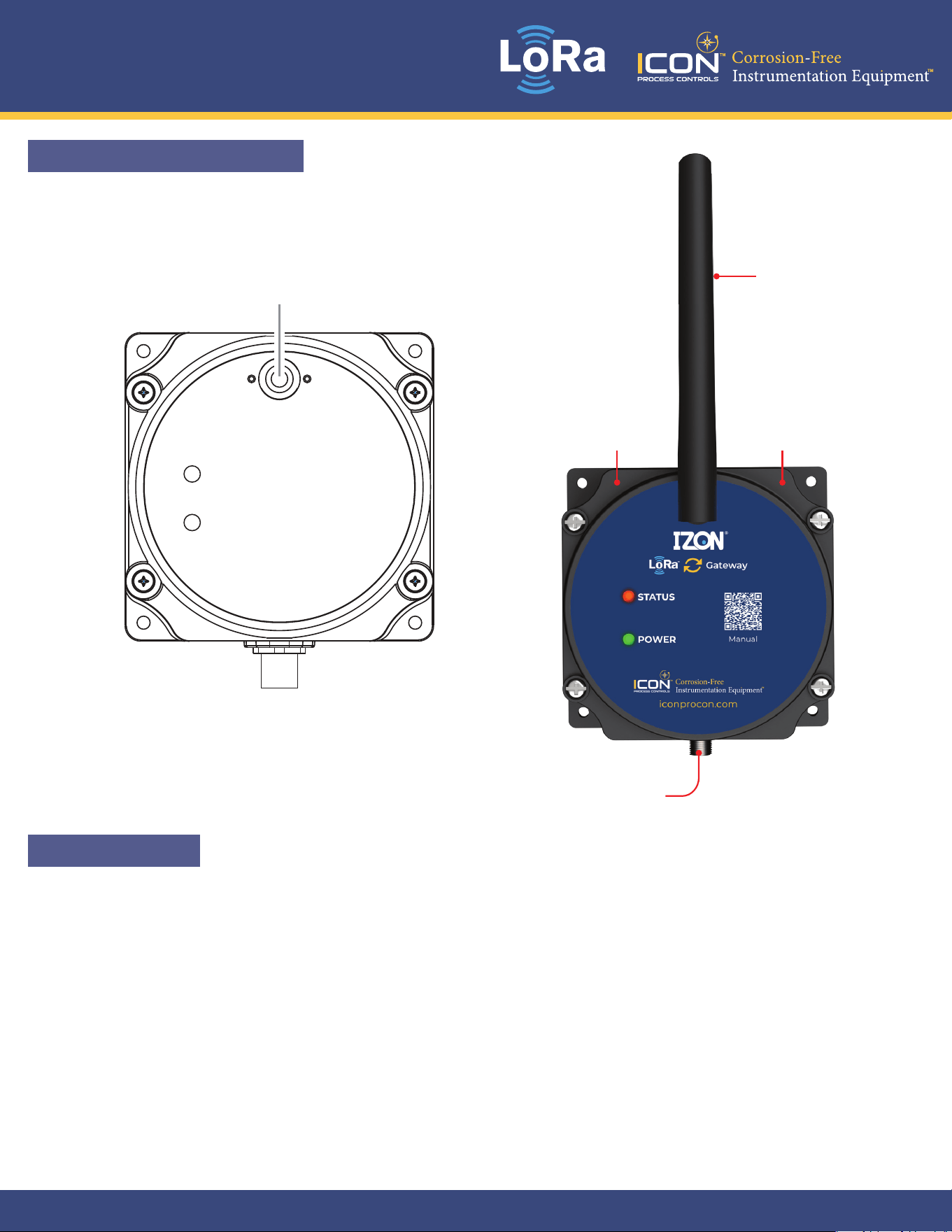
2. Product Introduction
3. Description
1
Interface
Antenna Connector
Introduction
STATUS
POWER
M12 Main Port
IP68
Enclosure
Corrosion Resistant
Housing
IZON
®
LRT-4000 LoRa Gateway is a high-performance communication gateway designed for reliable
long-range wireless data transmission. Operating within the 902-928 MHz frequency band, it ensures
stable and secure connectivity across industrial and remote monitoring applications.
Built for seamless integration, the gateway supports efcient data collection from multiple LoRa-enabled
devices and transmits information to centralized monitoring systems with minimal power consumption.
Its robust design makes it ideal for demanding environments where dependable communication is
critical.
The Izon
®
LoRa Gateway delivers extended coverage, strong signal penetration, and scalable network
capability, making it a smart solution for modern IoT deployments.
Antenna
IZON
®
LRT-4000 Series
Long Range Wireless Transmitter
426-1039 © Icon Process Controls Ltd.
4. Specifications
Product Type Indoor / Outdoor LoRa Gateway
Air Stream Protocol LoRa Wireless Protocol (LoRaWAN not supported)
Operating Frequency Range 902MHz~928MHz
Sensitivity Up to -137dBm@SF=8 / 10.4K bandwidth
Transmit RF Power Maximum 100mW
Interface Analog 4-20mA or Digital Input x 1 | RS-485 x 1 | Digital Output x 1
RS-485 Protocol Modbus RTU
Serial Baud Rate
1200bps / 2400bps / 4800bps / 9600bps / 19200bps / 38400bps / 57600bps / 115200bps
/ 230400bps / 460800bps
Transmit Encryption AES 128 / 256 Encryption Function
Analog Input Analog Input Support 0~10 V / 0~20 mA / 4~20 mA / ADC (0~10 V)
Digital Input Digital Input Support High / Low Signal Judge
Digital Output Type Open Drain
Digital Output Mode Digital Output Support PWM / Latch Mode
Operating Temperature -40°C ~ 85°C | -40°F ~ 185°F
Topology Broadcast / Group / Peer to Peer
Main Unit Dimensions 10 x 10 x 4.8 cm (Does not include antenna and external connect)
Weight 184 g
Waterproof IP68
Input Power Supply 12V – 36VDC / 1A
Output Power Supply Main Port: Vin=Vout / 40mA (Max.)
Power Consumption
24V 2.75mA @ 920MHz (Receive)
24V 85mA @ 100mW 920MHz (Transmit)
Special Specication Flame Retardant
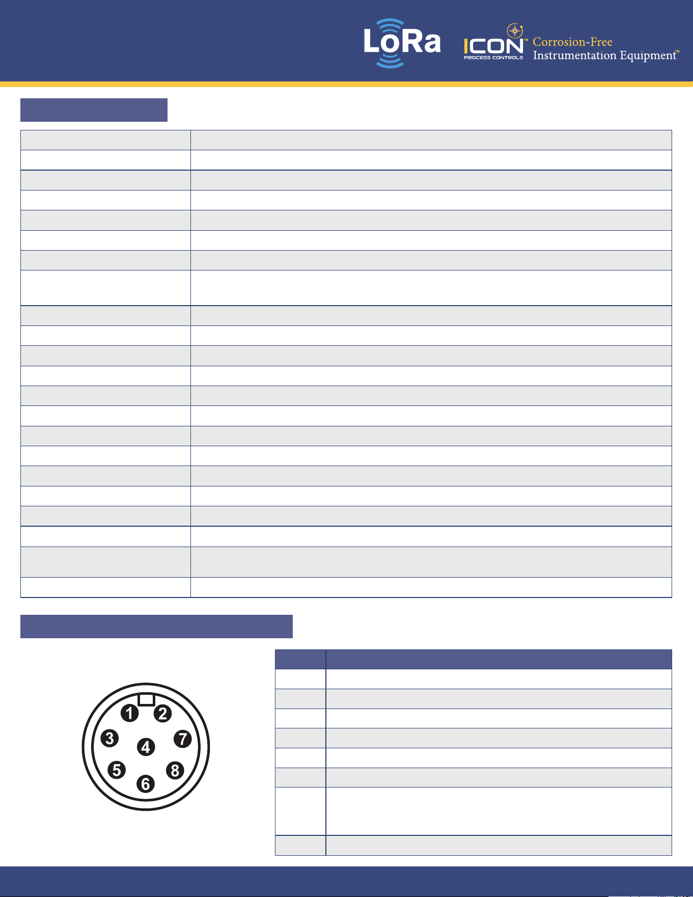
5. Main Port M12 Pin Assignment
Pin Description
1 DC in+: 12V to 36V DC / 1A
2 DC in-: GND
3 DC out+: Vin = Vout / 40mA MAX / Sensor+
4 DC out-: GND
5 RS-485 A: Non-isolator differential interface, Data-
6 RS-485 B: Non-isolator differential interface, Data+
7
A / D input:
Analog Input Support 0~10 V / 0~20 mA / 4~20 mA / ADC (0~10 V)
Digital Input support High / Low signal judge
8 D Output / Sensor-
Indicator
AUX I / O Remote Command
Interface
DC in+: 12V to 36V DC / 1A
DC in-: GND
DC out+: Vin ≒ Vout / 40mA MAX
DC out-: GND
RS-485 A: Non-isolator differential interface, Data-
RS-485 B: Non-isolator differential interface, Data+
A / D input:
Analog Input Support 0~10 V / 0~20 mA / 4~20 mA / ADC (0~10 V)
Digital Input support High / Low signal judge
D output: Digital Output support PWM / Latch Mode
1
2
3
4
5
6
7
8
- Main Port
Antenna Connector: RP-SMA-Female
Additional command information is available at www.win-tec.com.tw
- Status Indicator
Green lights stay on: Wireless data receiving.
Red lights stay on: Wireless data transmission.
- Power Indicator
Green lights stay on: Power ready.
Red lights stay on: Entry setup mode.
Green + Red lights stay on: Main part entry boot mode.
2
Antenna Connector: RP-SMA-Female
IZON
®
LRT-4000 Series
Long Range Wireless Transmitter
526-1039 © Icon Process Controls Ltd.
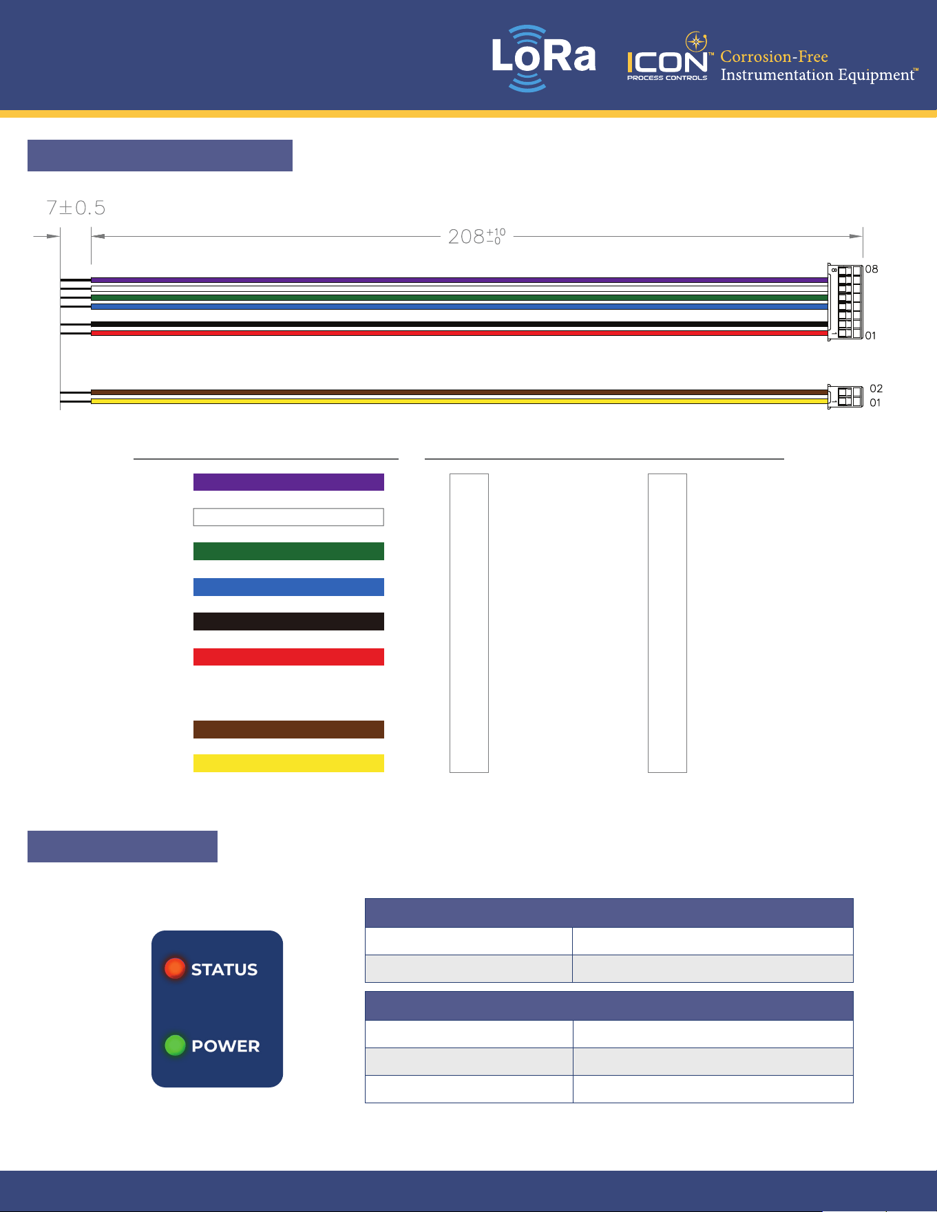
Flying Lead
Pin FunctionCord end Terminal Color
Purple
White
Green
Blue
Black
Red
Brown
Yellow
A / D input
RS-485 B
RS-485 A
DC out-
DC in-
DC in+
Sensor- input
Sensor+ input
A / D input
RS-485 B
RS-485 A
DC out-
DC in-
DC in+
D output (Open Drain)
DC out+
Master Node
6. Wiring – Flying Lead
7. LED Indicator
Status Indicator
Green Light On Wireless data is being recieved
Red Light On Wireless data is being transmitted
Power Indicator
Green Light On Power is ready
Red Light On Device is in Setup Mode
Green + Red Light On Device is in Boot Mode
IZON
®
LRT-4000 Series
Long Range Wireless Transmitter
626-1039 © Icon Process Controls Ltd.
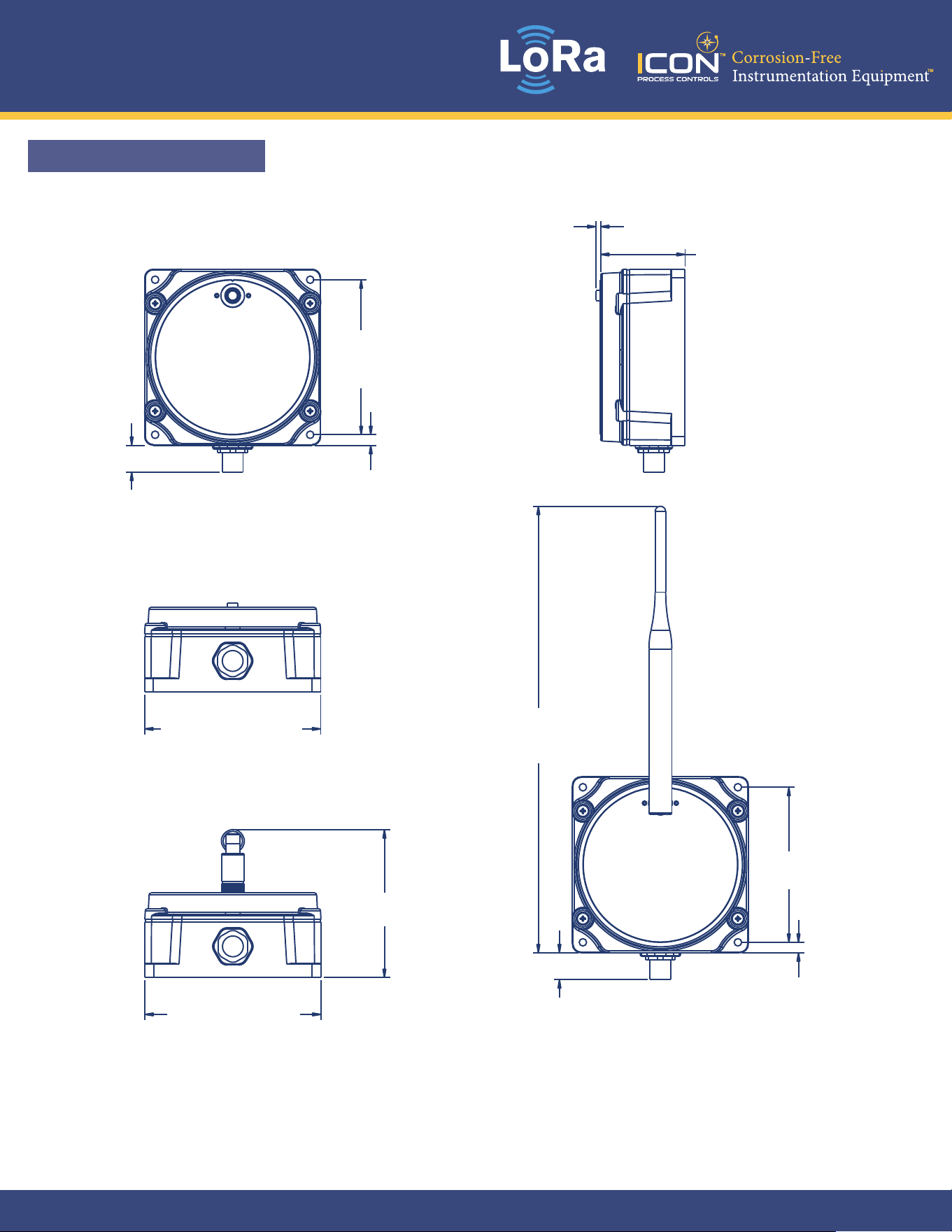
8. Dimensions (mm)
88
[3.46”]
2.6 [0.1”]
48 [1.89”]
6 [0.24”]
15.2 [0.6”]
100 [3.94”]
253.5 [9.98”]
88 [3.46”]
84 [3.31”]
100 [3.94”]
6 [0.24”]
15.2 [0.6”]
IZON
®
LRT-4000 Series
Long Range Wireless Transmitter
726-1039 © Icon Process Controls Ltd.
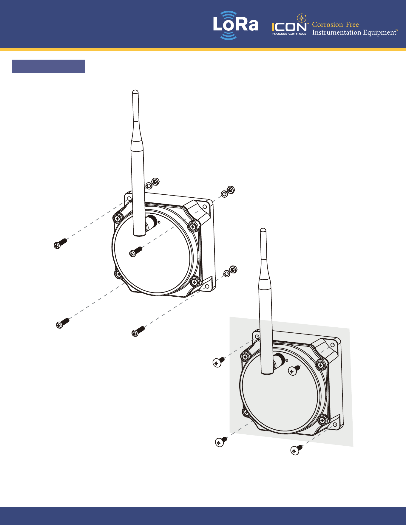
9. Installation
Wall
Assembling
5
IZON
®
LRT-4000 Series
Long Range Wireless Transmitter
826-1039 © Icon Process Controls Ltd.
10. Communication
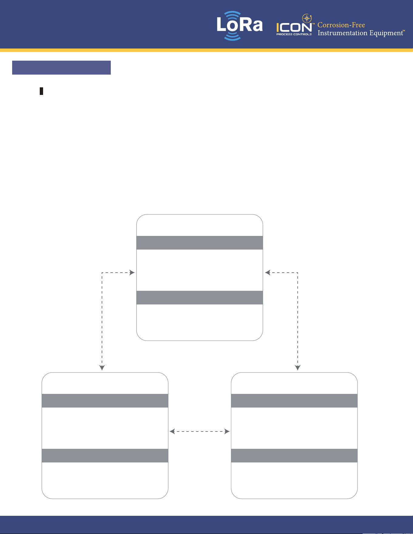
Broadcast Mode
6
Communication Instance
This is the simplest transfer method, and we recommend using it when switching
from wired to wireless.
When the RX Packet setting is set to “Broadcast Only,” the device will receive
broadcast packets only. In this mode, the RX Node Address and RX Group Address
are not used.
When the TX Packet setting is set to “Broadcast,” the device will transmit a broadcast
packet to all devices, and the TX Node Address and TX Group Address are not used.
RS485 Address : 100
RX Packet : Broadcast Only
RX Node Address : 1
RX Group Address : 128
TX Packet : Broadcast
TX Node : 100
TX Group : 128
RS485 Address : 101
RX Packet : Broadcast Only
RX Node Address : 1
RX Group Address : 128
TX Packet : Broadcast
TX Node Address : 100
TX Group Address : 128
RS485 Address : 102
RX Packet : Broadcast Only
RX Node Address : 1
RX Group Address : 128
TX Packet : Broadcast
TX Node Address : 100
TX Group Address : 128
Device #1 Device #2
Device #0
IZON
®
LRT-4000 Series
Long Range Wireless Transmitter
926-1039 © Icon Process Controls Ltd.
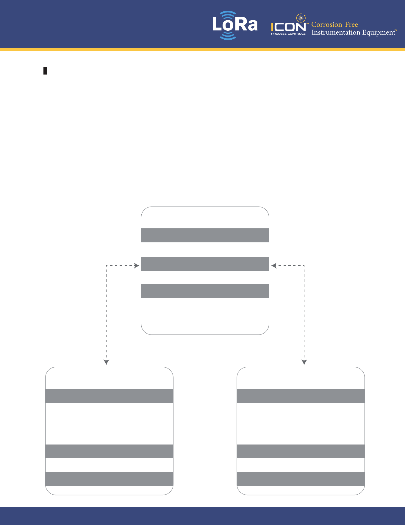
Master / Node Mode
7
If you have a master device and you don’t want the node devices to communicate
with each other, you can configure them as follows. When the Master RX Packet
setting is “Group Only” and the RX Group Address is 130, and both Node1 and Node2
have their TX Packet setting set to “Group” with a TX Group Address of 130, it means
Node1 and Node2 will transmit only to the master.
As a result, the nodes will not communicate with each other. When the Master TX
Packet setting is “Broadcast,” and Node1 and Node2 have their RX Packet setting set
to “Broadcast Only,” the nodes will receive only broadcast packets. This ensures that
Node1 and Node2 receive packets from the master only.
RS485 Address : 100
RX Packet : Group Only
RX Node Address : 1
RX Group Address : 130
TX Packet : Broadcast
TX Node Address : 100
TX Group Address : 128
RS485 Address : 101
RX Packet : Broadcast Only
RX Node Address : 1
RX Group Address : 128
TX Packet : Group
TX Node Address : 100
TX Group Address : 130
RS485 Address : 102
RX Packet : Broadcast Only
RX Node Address : 1
RX Group Address : 128
TX Packet : Group
TX Node Address : 100
TX Group Address : 130
Slave 1 Slave 2
Master
IZON
®
LRT-4000 Series
Long Range Wireless Transmitter
1026-1039 © Icon Process Controls Ltd.