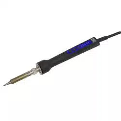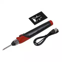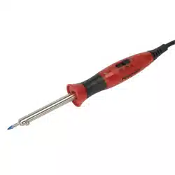
PROFESSIONAL SOLDERING IRON WITH
LONG LIFE TIP DUAL WATTAGE 15/30W &
40/80W 230V
MODEL NO: SD1530 & SD4080
Thank you for purchasing a Sealey product. Manufactured to a high standard, this product will, if used according to these
instructions, and properly maintained, give you years of trouble free performance.
IMPORTANT: PLEASE READ THESE INSTRUCTIONS CAREFULLY. NOTE THE SAFE OPERATIONAL REQUIREMENTS, WARNINGS & CAUTIONS. USE
THE PRODUCT CORRECTLY AND WITH CARE FOR THE PURPOSE FOR WHICH IT IS INTENDED. FAILURE TO DO SO MAY CAUSE DAMAGE AND/OR
PERSONAL INJURY AND WILL INVALIDATE THE WARRANTY. KEEP THESE INSTRUCTIONS SAFE FOR FUTURE USE.
1. SAFETY
1.1. ELECTRICAL SAFETY
WARNING! It is the responsibility of the owner and the operator to read, understand and comply with the following:
You must check all electrical products, before use, to ensure that they are safe. You must inspect power cables, plugs, sockets
and any other connectors for wear or damage. You must ensure that the risk of electric shock is minimised by the installation of
appropriate safety devices. A Residual Current Circuit Breaker (RCCB) should be incorporated in the main distribution board. You
must also read and understand the following instructions concerning electrical safety.
9 Ensure that cables are always protected against short circuit and overload.
9 Regularly inspect power supply cables and plugs for wear or damage and check all connections
to ensure that none are loose.
9 Ensure that the voltage marked on the appliance matches the power supply to be
usedandthattheplugisttedwiththecorrectfuse-seefuseratingatright.
8 DO NOT use worn or damaged cables, plugs or connectors. Have any faulty item repaired or
replaced immediately by a competent electrician.
9 It is recommended that this device is wired directly to a fused isolator switch. If, however, a plug
istted,thefollowingapplies:
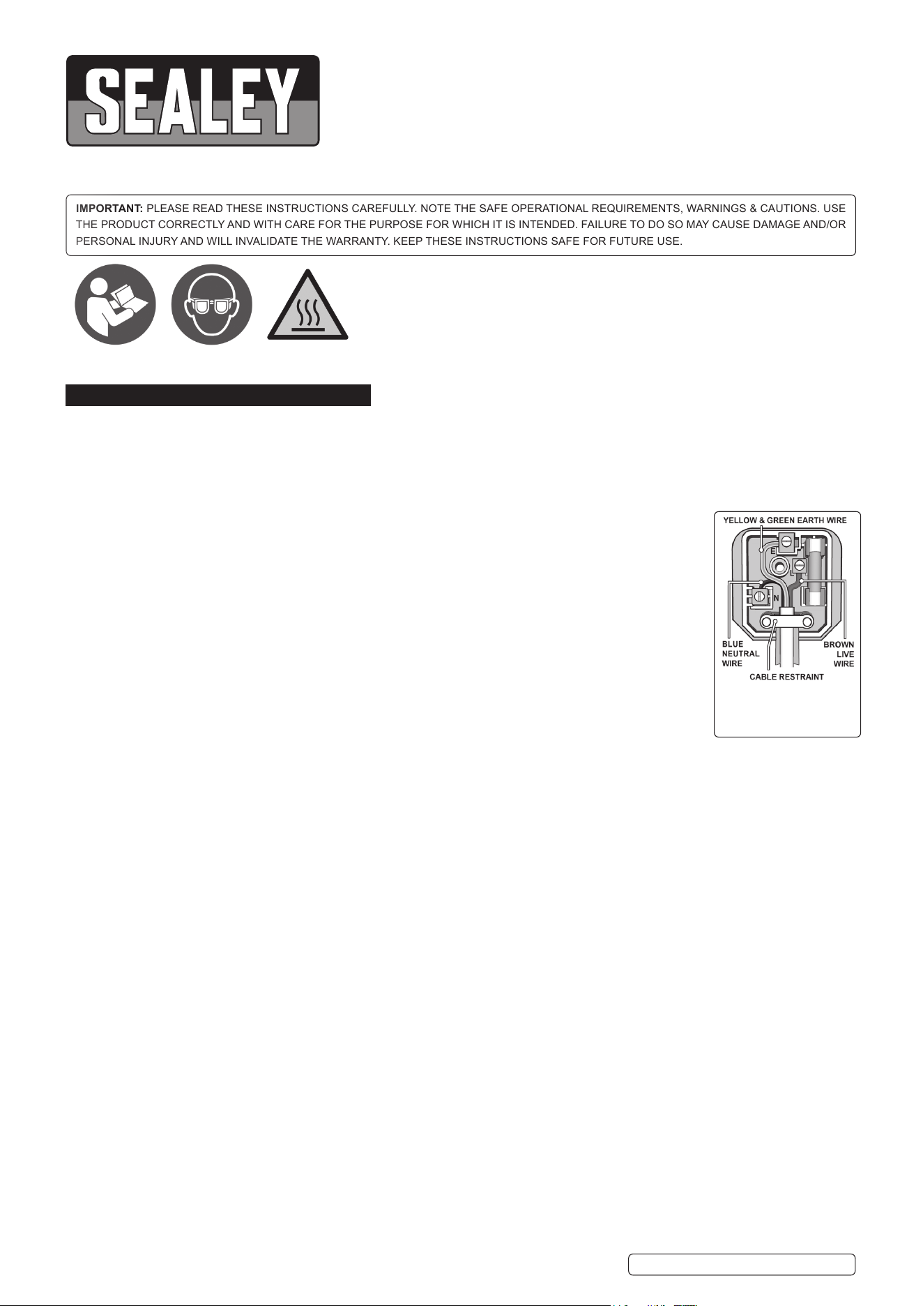
9 Fit a new plug according to the following instructions (UK only).
a) Connect the GREEN/YELLOW earth wire to the earth terminal ‘E’.
b) Connect the BROWN live wire to the live terminal ‘L’.
c) Connect the BLUE neutral wire to the neutral terminal ‘N’.
d) After wiring, check that there are no bare wires, that all wires have been correctly connected,
that the cable restraint is tight.
1.2. GENERAL SAFETY
WARNING! Ensure Health & Safety, local authority, and general workshop practice regulations are adhered to when using this
equipment.
9 Familiarise yourself with the application, limitations and potential hazards of the soldering iron.
9 Replace or repair damaged parts. Use genuine parts only. Non-authorised parts may be dangerous and will invalidate the warranty.
9 Locate in a suitable work area, keep the work area clean and tidy, and free from unrelated materials. Ensure there is adequate lighting.
9 Keep the soldering iron clean for best and safest performance.
9 Ensure there are no flammable or combustible materials near the work area.
9 Wear approved safety eye protection (standard spectacles are not adequate).
9 Wear appropriate protective clothing.
9 Removeillttingclothing,ties,watches,ringsandotherloosejewelleryandcontainlonghair.
9 Ensure the work piece is adequately held before operating the soldering iron.
9 Always use the stand provided for the soldering iron, so that the tip cannot make contact with the work surface.
9 Ensure that when the soldering iron is put down during use, that the tip is not near to, or in contact with any material that may burn or melt,
including the products own supply lead.
9 Remove excess solder from the soldering iron by wiping the tip on a damp sponge.
8 DO NOT attempt to remove excess solder from the soldering iron by shaking it, as hot solder may become airborne and land on skin
causing burns and blisters.
8 DO NOT allow children or pets into the area where the soldering is taking place.
8 DO NOT attempt to cool the soldering iron with water.
WARNING! Disconnect the soldering iron from the mains supply and allow it to cool before changing tips.
8 DO NOT operate the soldering iron when you are tired, under the influence of alcohol, drugs or intoxicating medication.
8 DO NOTleaveahotsolderingironunattended.-Ifleavingtheworkarea,evenforashortperiodoftime,switchitoffandallowtocool.
8 DO NOT use the soldering iron for any purpose other than that for which they have been designed.
8 DO NOT touch the work piece immediately after working on it, as it will be very hot. Allow it to cool.
8 DO NOT allow untrained persons or children to operate the soldering iron.
8 DO NOT operate the soldering iron if damaged.
8 DO NOT hold the work piece by hand.
9 When finished working, store the soldering iron in a safe, dry, childproof location.
Recommended fuse rating
3 Amp
SD1530 SD4080 Issue 4 (1) 03/06/21
Original Language Version
© Jack Sealey Limited
Refer to
instructions
Hot surfaces Wear eye
protection
2. INTRODUCTION
Ergonomichandledesignwithcomfortablegrip,LEDindicatorand3-positionswitch.Dualwattagesettingsallowtheusertocarryoutwork
requiringdierenttemperatures.Fittedwithhighqualitylong-lifetipsuitableforlead-freesolderingand1.3mcablewith3-pinplug.Features
knurled collar for quick and convenient tip replacement. Supplied with metal stand.
3. SPECIFICATION
Model No:................................................................. SD1530 ...............................................................SD4080
Consumable Parts: ................................................ SD1530/T ............................................................SD4080/T
Power Rating: ............................................................15/30W ............................................................... 40/80W
4. OPERATION
4.1. Thesolderingironisprimarilyintendedforthesolderingofelectricaljointssuchastheattachmentofcomponentstoprinted
circuit boards and the connection of leads to plugs and sockets used in electronics. (Where delicate electronic components are
concerned that may be damaged by excessive heat, the wire being soldered should be held with a pair of thin nosed pliers on the
opposite side of the board so that some of the heat generated by the soldering process is transferred to the pliers.)
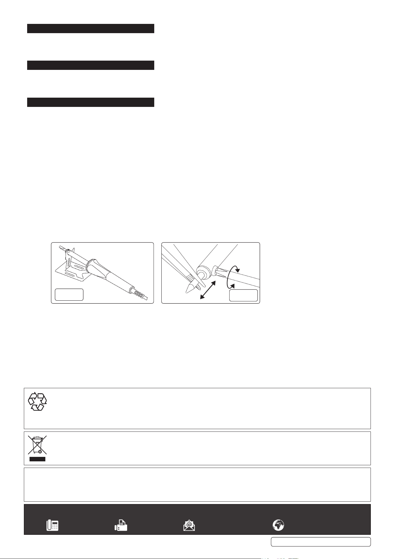
4.2. Before using the soldering iron, set up the metal stand provided by bending the centre section upwards so that it is at an angle of
nearly 90° to the rest of the stand (fig.1). Rest the soldering iron on the stand. Plug the iron into the mains supply and slide the switch
to either position ‘I’ or ‘II’, for the desired wattage setting. Leave the iron on the stand, for it to heat up.
4.3. When the iron is up to temperature, “tin” the tip by melting a thin layer of solder over the end of it. If any difficulty is experienced in
getting the solder to take to the tip, use a proprietary tip cleaner/tinning product.
4.4. Theitemstobesolderedmustbeperfectlycleanandfreefromgrease.Ideally,thetwoitemstobejoined(suchastheendofawire
andaswitchterminal)shouldbeindividuallytinnedbeforebeingbroughttogethertoensureagoodjoint.
4.5. Ensure that the items to be soldered are accessible and are securely held together.
4.6. Bringthetipofthesolderingironandthesoldertothejointsimultaneously.Leavetheirononthejointjustlongenoughtomelt
thesoldersothatitflowsontothetwopartstobejoined.Replacethesolderingirononthestand.Leavethejointtocool.When
finished working, slide the switch to the ‘0’ position and unplug the iron from its supply. Allow it to fully cool before storing it away.
4.7. DO NOT allow solder to accumulate where the tip enters the iron as this may make the tip difficult to remove. DO NOT get
solder deposits on the tip retaining screw as it may prevent a screwdriver fitting into the cross head. Periodically loosen the tip
retaining screw and rotate the tip in the iron to prevent it seizing into the body. Use a proprietary tip cleaner/tinner to keep the tip clean
and correctly tinned.
4.8. When the soldering iron is not in use but still hot, ensure that when it is put down, the tip is not touching, or close to, any material that
will melt or is inflammable.
4.9. After a prolonged period of service the tip may become pitted and need replacing. Disconnect the soldering iron from the mains
supply and wait until the iron has completely cooled down. Loosen the tip retaining nut and pull out the old tip with a pair of pliers.
DO NOT use pliers to insert the new tip as the plating may be damaged.) Insert the new tip and twist it into the orientation you
require. Lock the tip in place by tightening the retaining screw (fig.2).
4.10. SealeyPartNo’sforReplacementtips:ModelNo.SD1530-SD1530/T,ModelNo.SD4080-SD4080/T.
g.1
g.2
Sealey Group, Kempson Way, Suffolk Business Park, Bury St Edmunds, Suffolk. IP32 7AR
01284 757500 01284 703534 sales@sealey.co.uk www.sealey.co.uk
ENVIRONMENT PROTECTION
Recycle unwanted materials instead of disposing of them as waste. All tools, accessories and packaging should be sorted, taken to
a recycling centre and disposed of in a manner which is compatible with the environment. When the product becomes completely
unserviceable and requires disposal, drain any fluids (if applicable) into approved containers and dispose of the product and fluids
according to local regulations.
WEEE REGULATIONS
Dispose of this product at the end of its working life in compliance with the EU Directive on Waste Electrical and Electronic Equipment
(WEEE). When the product is no longer required, it must be disposed of in an environmentally protective way. Contact your local solid
waste authority for recycling information.
Note: It is our policy to continually improve products and as such we reserve the right to alter data, specifications and component parts without prior
notice.
Important: No Liability is accepted for incorrect use of this product.
Warranty: Guarantee is 12 months from purchase date, proof of which is required for any claim.
SD1530 SD4080 Issue 4 (1) 03/06/21
Original Language Version
© Jack Sealey Limited