Digital Two Way Radio
SkyConnex Communications Limited
Instruction Manual

2
Attention
Please read this instruction manual carefully before use.
Please keep this manual, which contains important instructions on the use of Digital Trunking portable
radio series.
△
!
Battery Usage Precautions.
Do not disassemble or modify the battery.
Batteries have internal protective circuitry, and disassembly or modification of the battery may
cause damage to the protective circuitry, and the battery may smoke, rupture, or catch fire.
Do not short-circuit the battery.
Do not use any metal to connect the "+" and "-" terminals of the battery, and do not place or
store the battery in a container with a metal object. If the battery is short-circuited, excessive
current will be drawn, and the battery will heat up, smoke, rupture, or catch fire.
Do not place the battery near a fire, furnace or other heater, and do not burn or heat the
battery.
Batteries may generate heat, smolder, rupture, or catch fire.
Do not expose the battery to rain, snow, seawater or any other liquids.
Do not charge or use wet batteries. If the battery gets wet, be sure to dry it before use.
△
!
Charger usage precautions.
Do not block the air vents of the charger, as this may cause damage to the internal parts and
result in electric shock or disaster.
Do not allow the charger to get close to heat sinks or heat sources; do not put paper under the
charger.
Do not place the charger in a closed container or on a bed, sofa or carpet.
Do not use the charger near bathtubs, pools, swimming pools or in wet basements.
Do not place metal sheets in the card holder, as these conductive materials may damage the
unit.
Do not press the power supply strongly enough to bend or distort the pins.
Do not leave the charger exposed to dirt, dust, water or food.
Do not expose the charger to high temperatures or sunlight.

3
Content
1. Overview ....................................................................................................................... 1
1.1 product description ...................................................................................................... 1
1.1.1 Product use .......................................................................................................... 1
1.1.2 product composition ............................................................................................. 1
1.1.3 Main functions ...................................................................................................... 1
1.2 product profile ............................................................................................................. 2
1.2.1 Brief description of the appearance of the whole machine ................................... 2
1.2.2 Interface layout ..................................................................................................... 3
1.2.3 Status bar icon indication ..................................................................................... 4
1.2.4 Introduction to the keyboard ................................................................................. 4
2. Working mode………………………………………………………..
2.1 Conventional mode……………………………………………
2.2 Trunking mode………………………………………………….
3. Mounting and dismounting ............................................................................................ 4
3.1 Pre-installation inspection ........................................................................................... 4
3.2 Battery mounting and dismounting .............................................................................. 4
3.3 antenna mounting and dismounting ............................................................................ 5
3.4 Belt clip mounting and dismounting ............................................................................ 6
3.4.1 Standard belt clip mounting and dismounting………………………..
3.4.2 Optional cradle clip mounting and dismounting
3.5 Accessories jack mounting and dismounting .............................................................. 7
4. Operating instructions .................................................................................................... 8
4.1 Basic operations ......................................................................................................... 8
4.1.1 Start-up operation ................................................................................................. 8
4.1.2 Power off operations ............................................................................................. 8
4.1.3 Volume adjustment ............................................................................................... 9
4.1.4 Channel/group switching……………………….
4.2 Conventional mode voice calls .................................................................................... 9
4.2.1 PTT call ................................................................................................................ 9
4.2.2 Manual dialing calls .............................................................................................. 9
4.2.3 Contact person paging ....................................................................................... 10
4.2.4 Contact list……………………………………………………….
4.3 Conventional mode MESSAGE communication ....................................................... 10
4.3.1 New MESSAGE.................................................................................................. 11
4.3.2 Status MESSAGE sending ................................................................................. 12
4.3.3 Sending Quick Text SMS
4.3.4 Text SMS reception
4.3.5 Inbox
4.3.6 Outbox
4.4 Zone selecting
4.5 Scanning Settings
4.5.1 Viewing a List
4.5.2 Setting an Effective List
4.6 Working Mode

4
4.7 Other Settings
4.7.1 Positioning Settings
4.7.2 Arbitrary Call
4.7.3 Language Settings
4.7.4 Power Setting
4.7.5 Display Settings
4.7.6 Prompt Sound Settings
4.7.7 Setting the standby interface
4.7.8 Keylock Settings
4.7.9 Time and Date Setting
4.7.10 Short message types
4.7.11 Encryption Settings
4.7.12 Displaying Adjacent Devices
4.7.13 Vibration Setting
4.7.14 Inversion Setting
4.7.15 Vocoder Types
4.7.16 Recording Export
4.8 Viewing Device Information
4.8.1 Viewing Local Information
4.8.2 LCD Information Viewing
4.8.3 Viewing Location Information
4.8.4 Viewing Battery Information
4.8.5 Viewing the List of Receiving Groups
4.8.6 Viewing Information on Adjacent Devices
5. Routine maintenance of the product ............................................................................ 13
5.1 Maintenance ............................................................................................................. 13
5.2 Cleaning .................................................................................................................... 14
6. transportation and storage ........................................................................................... 14
6.1 Requirements and methods of packing equipment ................................................... 14
6.2 Transportation ........................................................................................................... 14
6.3 Storage ..................................................................................................................... 15
6.3.1 Storage rules ...................................................................................................... 15
6.3.2 Requirements for warehouses ............................................................................ 15
6.3.3 Product storage period ....................................................................................... 15
1
1. Overview
1.1 Product description
1.1.1 Product use
The Digital Trunking portable radio series is a wireless communication terminal that
supports voice, Message, positioning information and other services.
1.1.2 Product composition
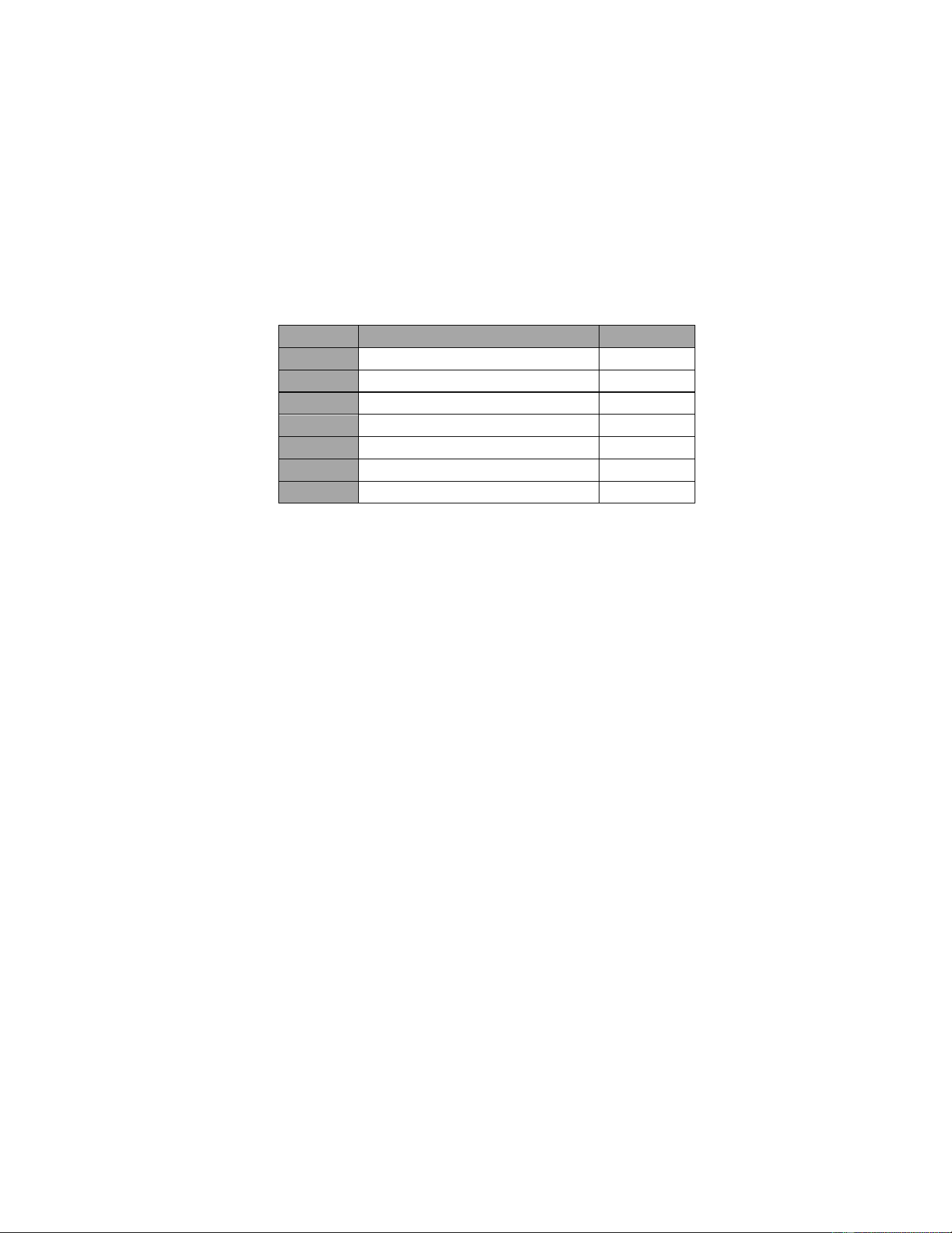
Table 1 Product composition table
NO.
Items
Quantity
1
Radio unit
1 pcs
2
Battery pack
1 pcs
3
Antennas
1 pcs
4
Charger
1 pcs
5
Adapter
1 pcs
6
Belt clip
1 pcs
7
Instruction manual
1 pcs
1.1.3 Main functions
1.1.3.1 Voice calls
Use the keypad to dial and then press PTT to call, realizing single call, group call, full call
and other functions.
1.1.3.2 Message
Support manual editing and preset Message, realize point-to-point and point-to-multipoint
Message function, support up to 60 characters per MESSAGE.
1.1.3.3 Satellite positioning information transmission
The terminal uses the positioning module to send positioning information to the system
and displays the device location information on the dispatch console via an electronic map.
1.1.3.4 Roaming
Under the Trunking mode, the terminal can automatically roam in any site in the
system and scan and register according to the site field strength.
1.2 Product profile
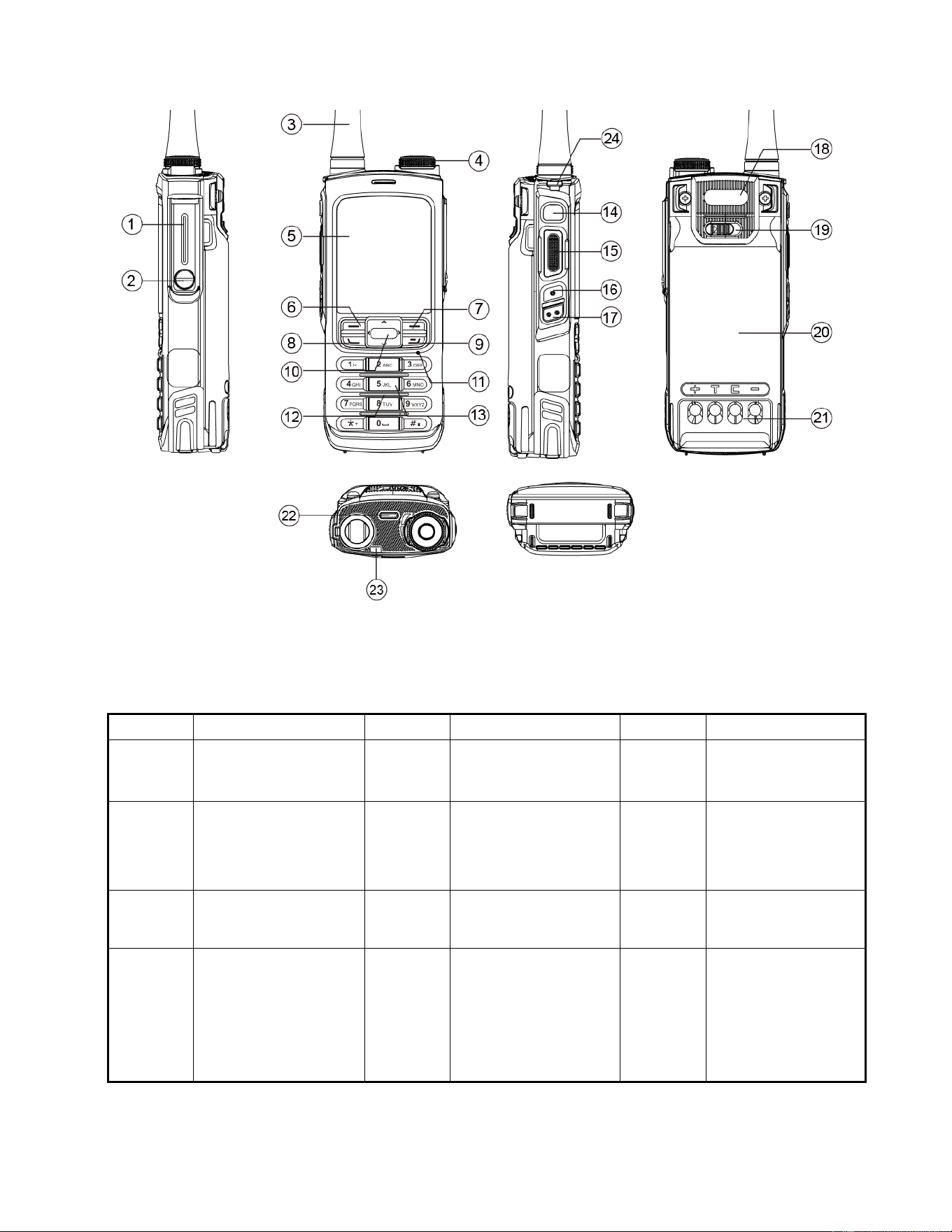
1.2.1 Brief description of the appearance
2
Fig. 1 Brief description of the appearance
Table 2 The exterior parts
S/N.
Parts
Serial
The name of the
Serial
The name of
1
Accessories
interface cover
9
Hang-up key
17
SK2 side key
2
Accessories
interface cover
screws
10
Direction keys
18
Logo labeling
3
RF antennas
11
MIC sound inlet
19
Battery clip
position
4
Volume/channel
knob
12
Speaker outlet
20
Cradle clip
(Optional
accessories)
position
3
5
LCD
13
Keypad
21
Battery charging
contacts
6
Menu/confirmation
key
14
Emergency call
key
22
Battery charging
contacts
7
Retune key
15
PTT key
23
Indicator LED
8
Call key
16
SK1 side key
24
Lanyard hole
1.2.2 Display Interface
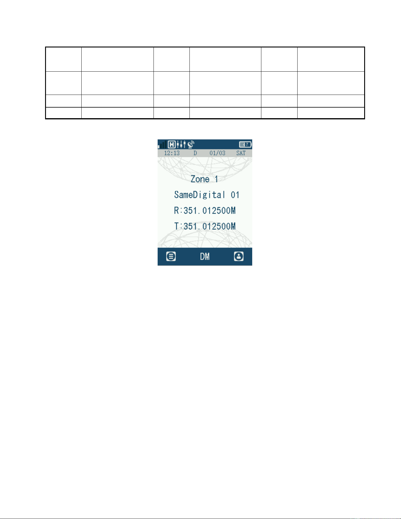
Figure 2 Layout of the interface
The interface is divided into: status display area, time display area, main display area, and
operation instruction area.
Status display area: display the current radio status icon, including signal strength, high
and low power indication, unread MESSAGE indication, positioning indication, alarm
indication, power indication, etc.;.
Time display area: displays the current time, date, day of the week, and channel mode.
Main display area: displays area name, channel name, receive frequency point, TX
frequency point.
Operating instructions area: displays menu, contact list, working mode.
4
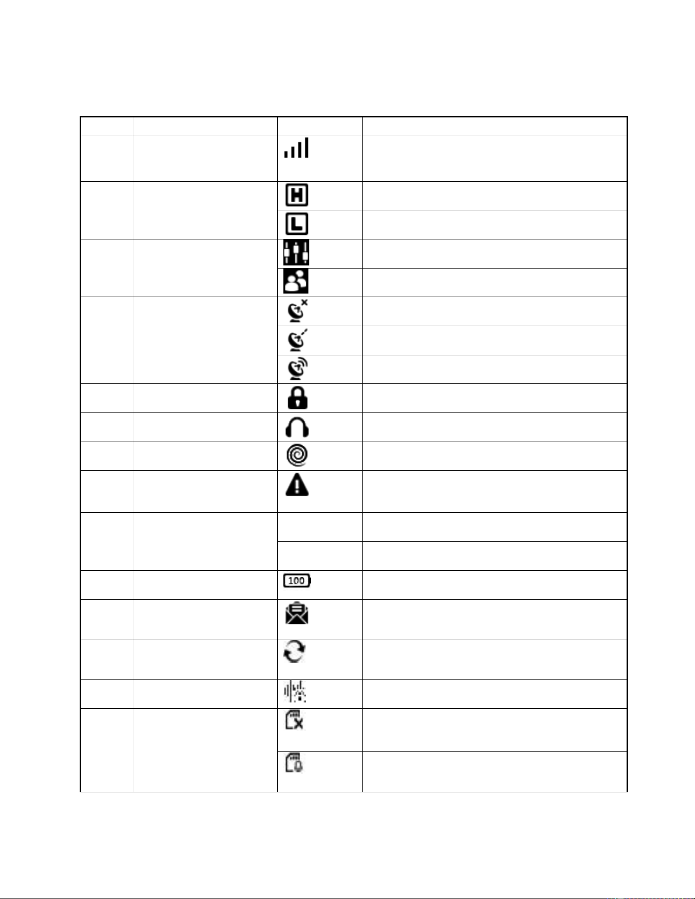
1.2.3 Status bar icon indication
Table 3 Status bar icon indications
Serial
The name of the icon
The icon
The icon indicates the content
1
signal strength
Signal Strength. The more signal cells you
have, the stronger the signal will be.
2
Transmit power
High power
Low power
3
Volume/channel knob
instructions
currently in volume adjustment mode
Currently in channel/group switching state
4
Positioning instructions
Positioning the unconnected icon
Positioning the being connected icon
Positioning success icon
5
Keypad lock
keypad lock indication
6
Earphones
earphones insertion indication
7
Stun state
Remote stun indication
8
Alarm status
radio failure or failure to write parameters or
frequency
9
model
DM
conventional mode indication
TM
Trunking mode indication
10
Battery capacity
Power level indication
11
unread text messages
There are unread text messages in your inbox
12
Scan
Indicates that the current radio is scanning
13
Encryption
Voice or data encryption enabled
14
Recording
Recording turned on but no storage card
detected
Recording turned on and storage card detected
5
1.2.4 Introduction to the keyboard
The radio keypad is composed of a standard 3*4 keypad, arrow keys, confirmation
keys, return keys, call keys and hang-up keys.
The 3*4 keypad allows for numeric, symbol, Chinese character and English input.
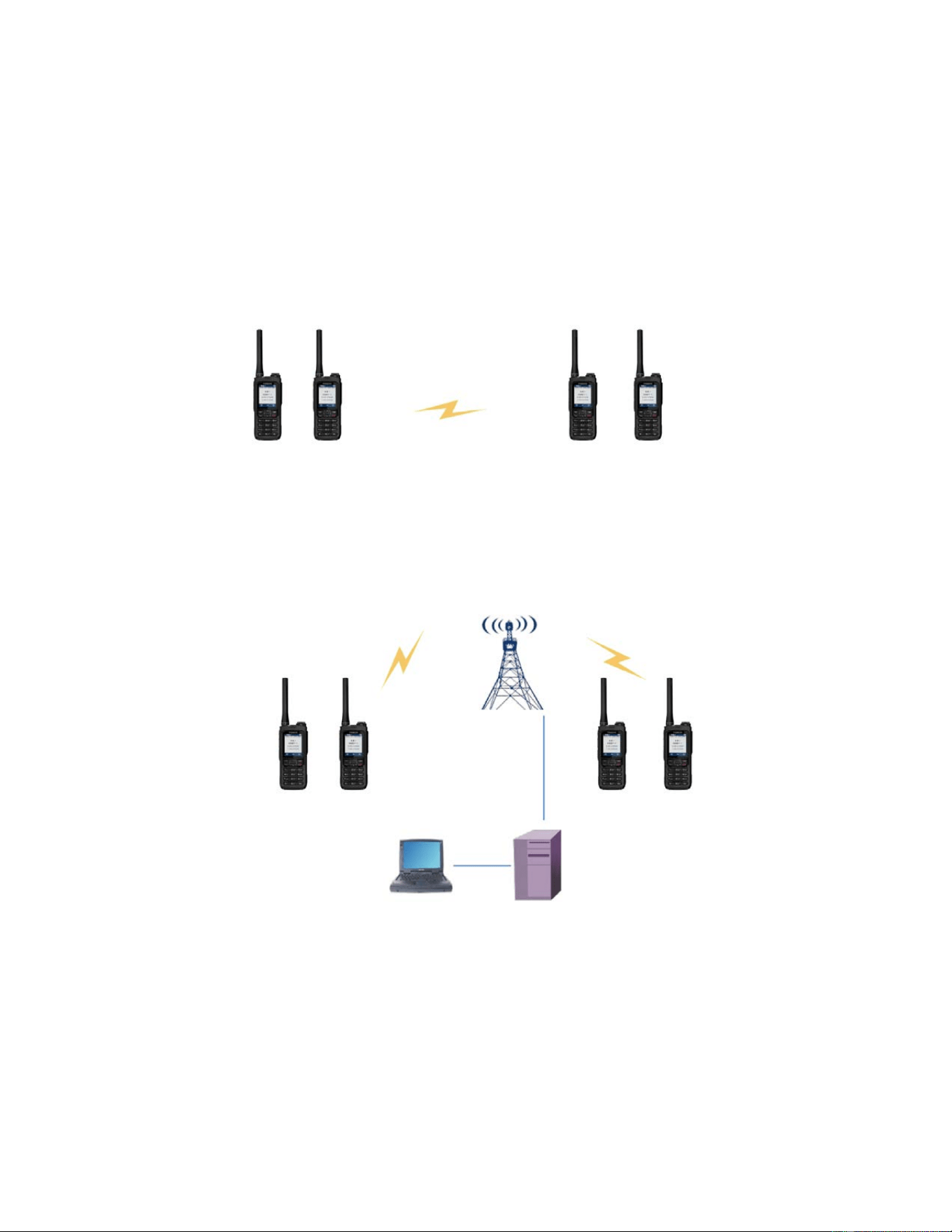
2. Working mode
2.1 Conventional mode
Figure 3 Conventional mode diagram
【DM】Conventional mode between radio through air interface wireless radio
frequency signals. This system only consists of radio terminals
2.2 Trunking mode
Figure 4 Trunking mode diagram
【TM】Composed of base stations, servers, dispatch stations, radio terminals, and other
device. The server and base station uniformly manage the frequency resources and
business requests of terminal devices.
6
3. Mounting and dismounting
3.1 Pre-installation inspection
Before installation, check that the required components are complete and of the
correct type in accordance with the product composition table.
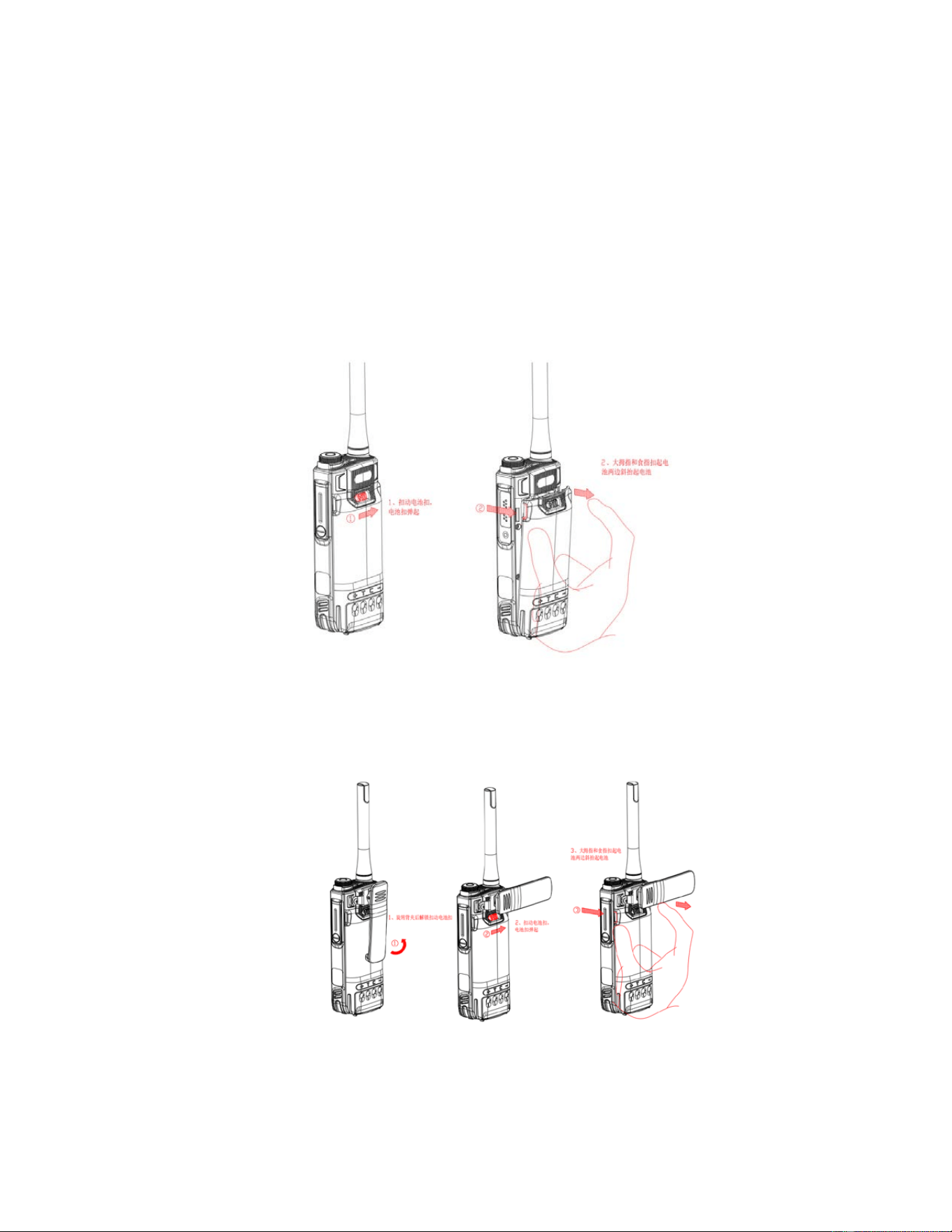
3.2 Battery mounting and dismounting
Insert the battery into the bottom slot as shown in the illustration, push the battery in the
direction shown in the illustration until you hear a "click" and the battery is installed.
Remove it by pushing the battery clasp upward in the direction of the arrow as shown in
the illustration, then just pull the battery outward in the direction of the arrow.
Fig. 5.1 Schematic diagram of mounting and dismounting
The schematic diagram for removing the battery after assembling the buckle is shown in the figure.
First, rotate the belt clip to a 90 degree position, and then pull the battery buckle to remove the
battery.
Fig. 5.2 Schematic diagram of battery mounting and dismounting
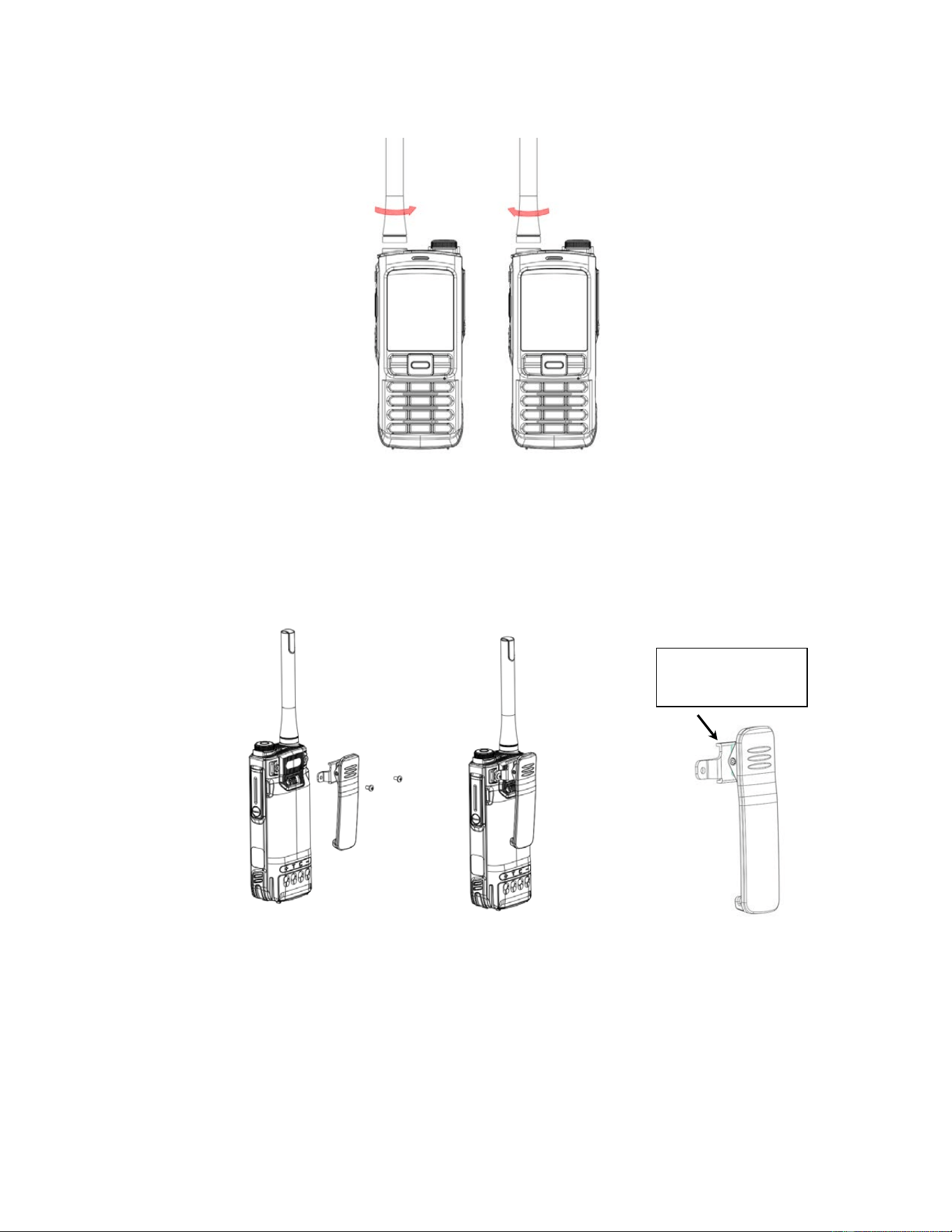
3.3 Antenna mounting and dismounting
Tighten the antenna clockwise into the antenna bay.
7
Unscrew the antenna counterclockwise.
Fig. 6 Schematic diagram of antenna mounting and dismounting
3.4 Belt clip installation and removal
3.4.1 Standard belt clip mounting and dismounting
The locking buckle screw is shown in the figure. Use a Phillips screwdriver to remove the
screw on the belt clip and secure it. Pay attention to the direction of the back clip, with
the long end facing upwards, as shown in the diagram
Figure 7.1 Schematic diagram of belt clip mounting and dismounting
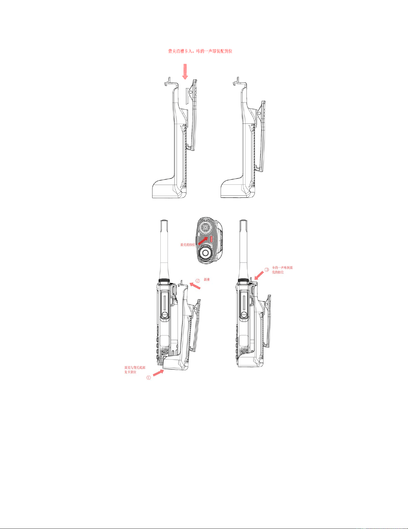
3.4.2 Optional cradle clip mounting and dismounting
Push the belt clip down into the slot of the cradle clip until you hear a "click".
Remove the belt clip on the cradle clip by pivoting the clip outward and pushing it upward.
Once the cradle clip is assembled in the manner described in Figure 8.2, the radio is in a
reliable mounting condition.
The way the back rest is disassembled is the reverse operation of the way it is
assembled.
The hardware position
is facing upwards at
this end
8
Figure 8.1 Schematic diagram of cradle clip mounting and dismounting
Figure 8.2 Schematic diagram of cradle clip mounting and dismounting
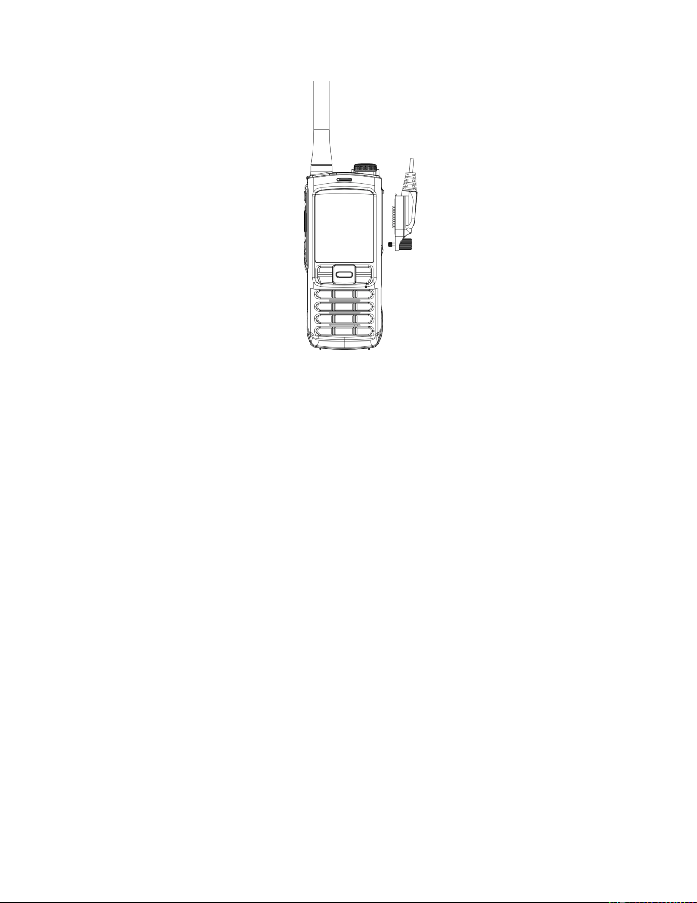
3.5 Accessories jack mounting and dismounting
Twist the screwdriver to remove the cover of the Accessories jack.
Snap the Accessories jack into the upper groove position, tighten the screw cap
clockwise until there is no gap on the contact surface of the Accessories jack, at this
time the Accessories jack mounting is complete.
Loosen the screw cap counterclockwise to remove the Accessories jack.
9
Fig. 9 Schematic diagram of accessories jack mounting and dismounting
4. Operating instructions
4.1 Basic operations
4.1.1 Start-up operation
4.1.1.1 Power on detection
Checking the screen for physical breakage.
Check if the antenna connection is correct.
Check that the batteries are installed correctly
4.1.1.2 Power on
Press and hold the [Switch / Hang-up key] for more than 2 seconds, and the radio
screen will display the startup interface, followed by the standby interface, and play the
startup prompt sound.
4.1.2 Power off
Press and hold the [Switch / Hang-up key] for more than 2 seconds, the radio screen
will display the power off interface, and then the display screen will close.
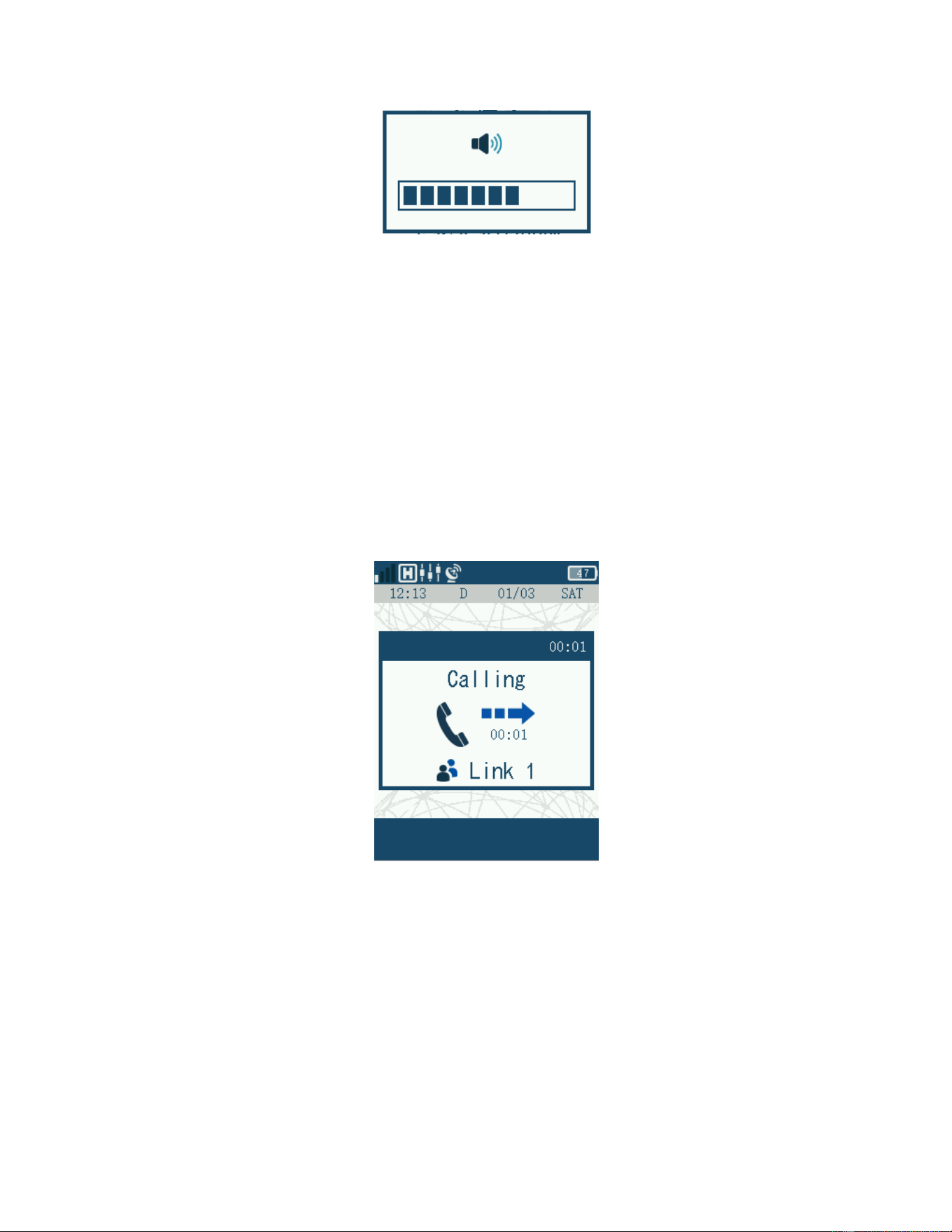
4.1.3 Volume adjustment
Select the volume adjustment mode by short pressing the [Volume/channel knob], and
the display screen status bar will display the volume adjustment icon. At this point, rotate
the [Volume/channel knob] clockwise to increase the volume. And rotate the
[Volume/channel knob] counterclockwise to decrease the volume.
10
Figure 10 Volume interface
4.1.4 Channel/group switching
Select the channel/group switching mode by short pressing the [Volume/channel knob],
and the channel/group switching icon will be displayed in the status bar of the display
screen. At this point, rotate the [Volume/channel knob] clockwise to switch channels
downwards on the radio. And rotate the [Volume/channel knob] counterclockwise to switch
channels upwards on the radio.
4.2 Conventional mode voice calls
4.2.1 PTT call
Press [PTT] in standby mode to initiate PTT call. At this time, the red indicator light is
on, and the LCD displays the called group number.
Figure 11 PTT call screen
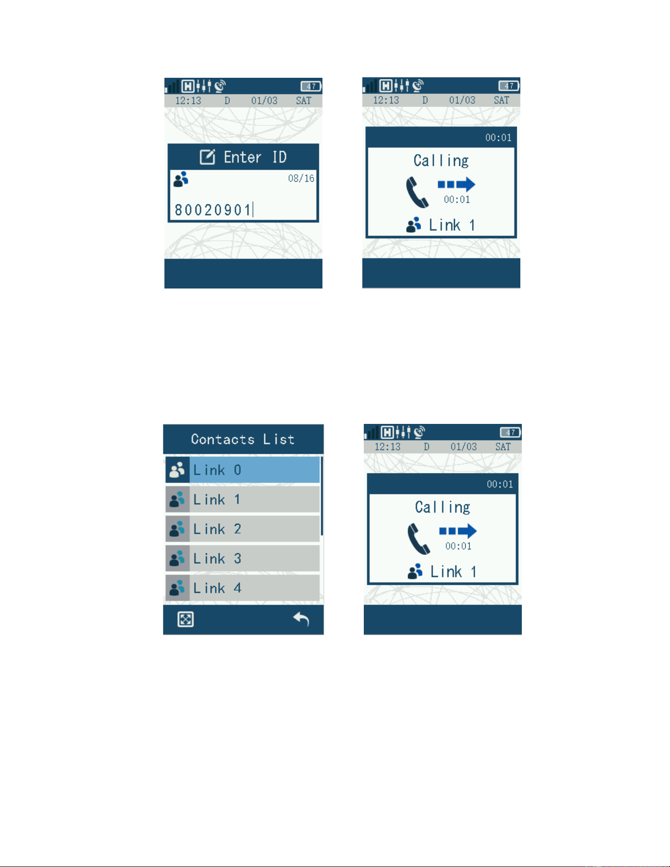
4.2.2 Manual dialing calls
Press [Call key] in standby mode to enter the dialing interface. Enter the target number,
and then press [PTT] to initiate a call. At this time, the red indicator lights up, and the LCD
displays the call status and number.
11
Figure 12 Dial-a-Call screen
4.2.3 Contact person paging
Press [Menu/confirmation key] in standby mode to enter the menu list interface, then
select "Contacts" to enter the contact menu, and then enter the "Contact List". Press [PTT]
at the selected contact to initiate a call. At this time, the red indicator light is on, and the
LCD displays the call status and contact.
Figure 13 Contact person paging interface
4.2.4 Contact list
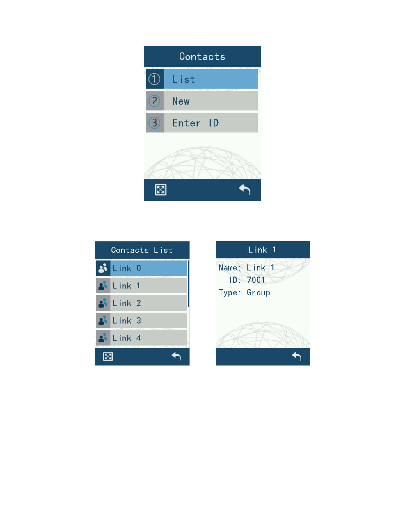
Enter the menu list and select "Contacts" to enter the contact menu. The contact menu
includes the following three submenus: contact list, new contact, and manual dialing.
12
Figure 14 Contacts interface
4.2.4.1 Contact list operation
Enter the Contact List to view contacts and their specific information. You can edit and
save the contact name and number, or delete contacts.
Figure 15 Contacts List interface
4.2.4.2 New Contact
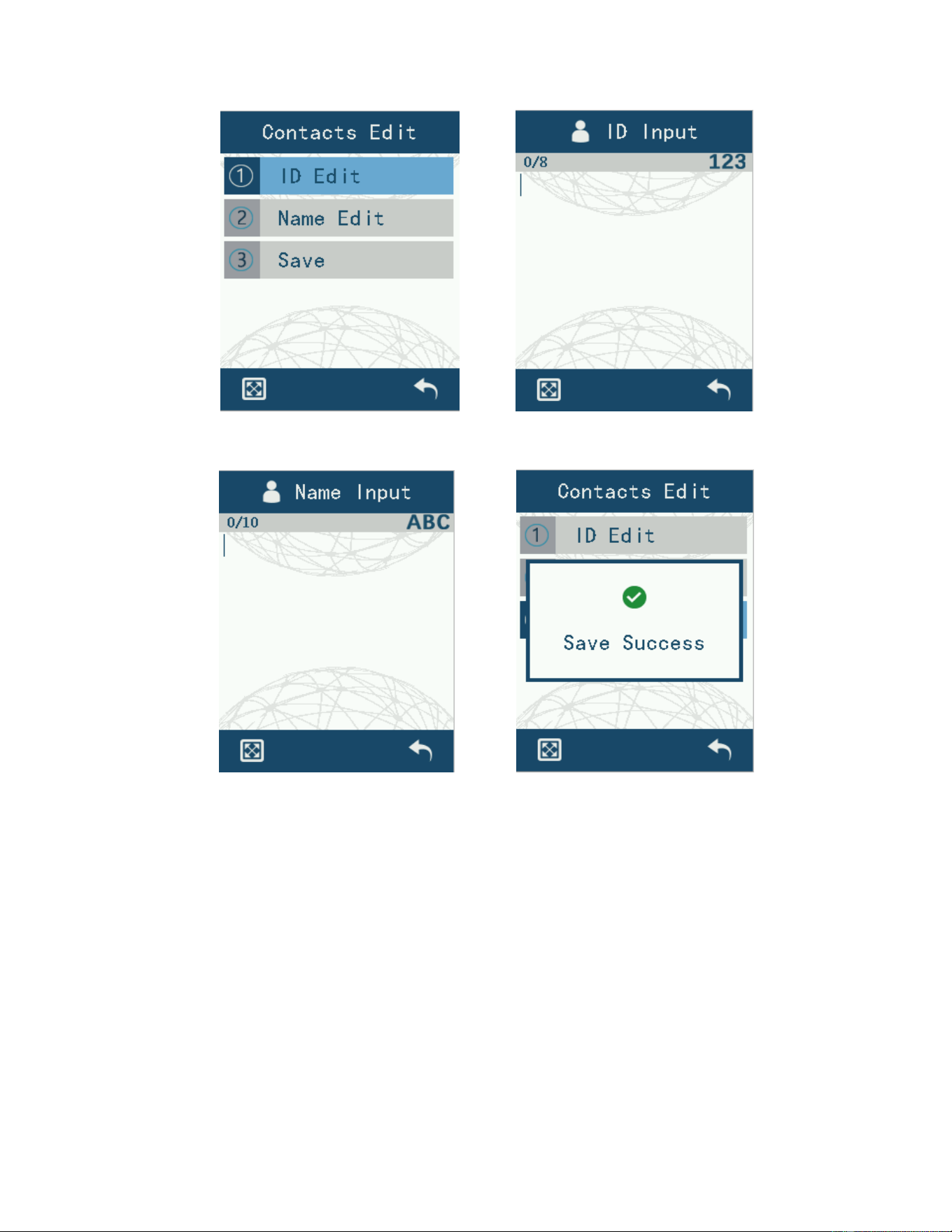
Enter to “New Edit”, select individual or group contact, edit the number, edit the name, and
then save the contact.
13
Figure 16 New contacts interface
4.3 Conventional mode Message communication
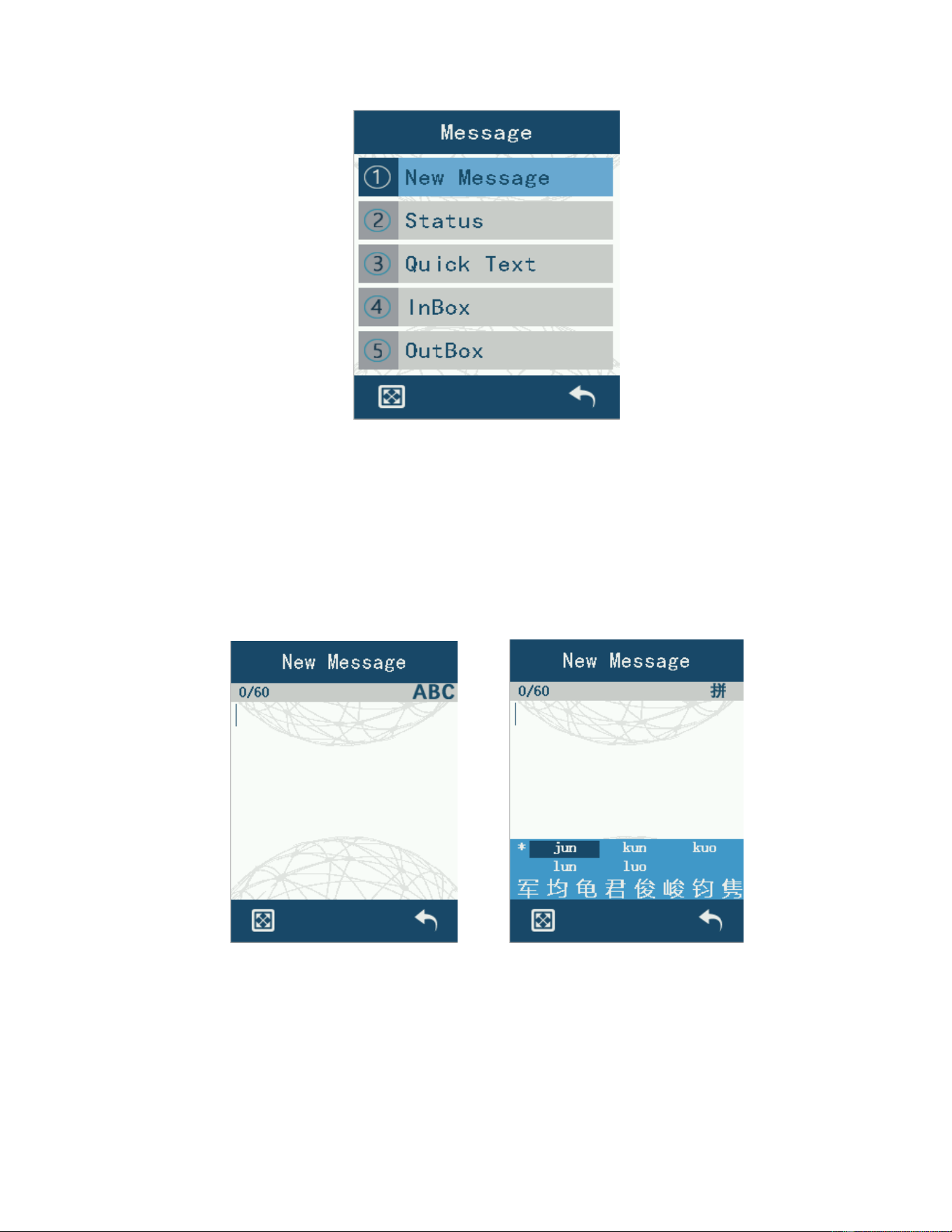
Enter the menu list and select “Message” to enter the MESSAGE menu. MESSAGE menu
contains five parts: New MESSAGE, Status MESSAGE, Quick Text, Inbox, Outbox.
14
Figure 17 Message interface
4.3.1 New message
Enter the menu list, select“Message”->“New Message” to enter the MESSAGE editing
interface. Input methods include uppercase English, Chinese Pinyin, numbers, lowercase
English, by pressing [#] key to switch the input method. And the [Left key] of [direction key]
can delete the entered content, [up key] and [down key] to switch the selected position,
[Return key] to return to the previous menu.
Figure 18 Message editing interface
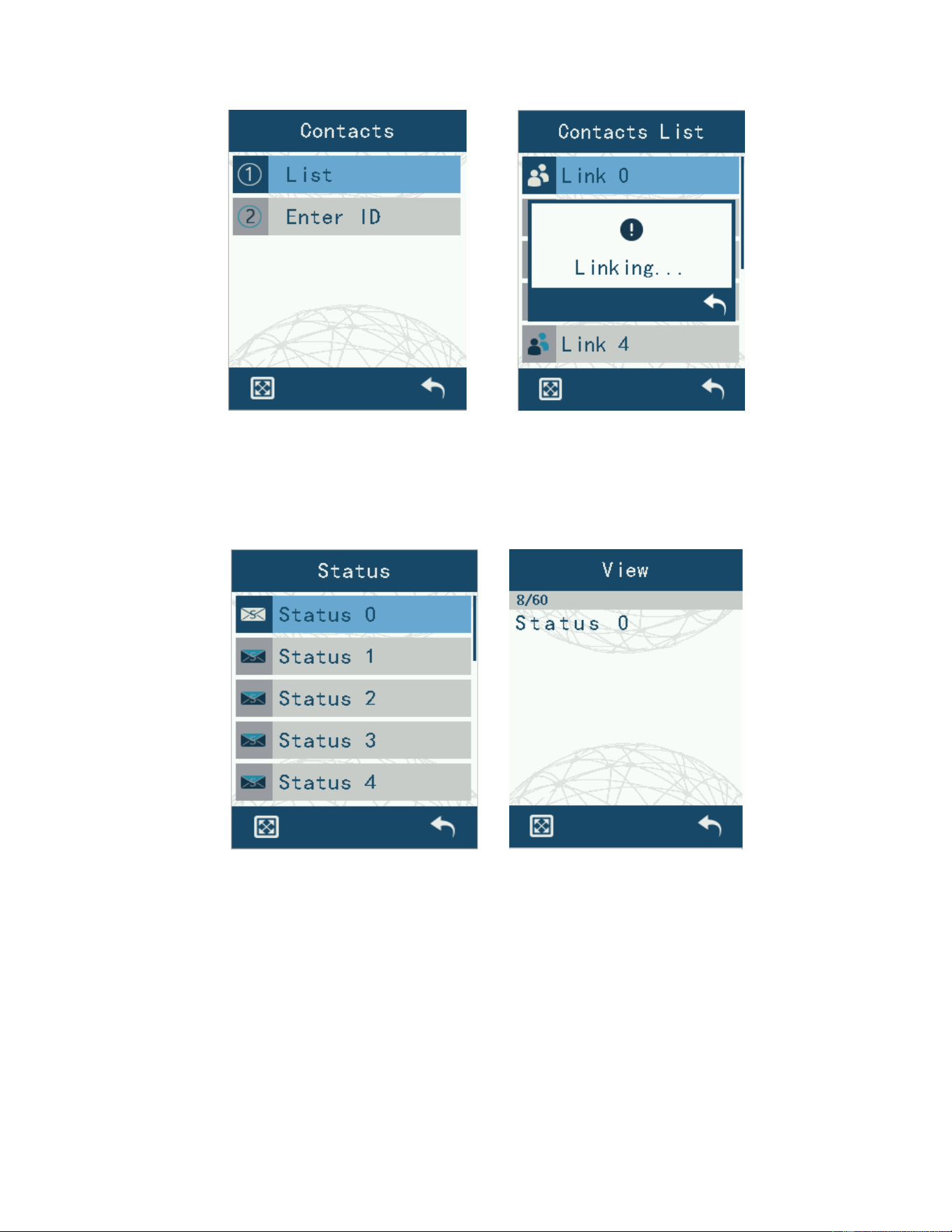
Send MESSAGE by selecting the contact list, or manually enter the number to send
MESSAGE.
15
Figure 19 Message sending interface
4.3.2 Status Message sending
Enter the menu list, select “Message”->”Status Message”, enter the “Status” list. In the list,
select the content with sending, use the [Menu/confirmation key] to view the specific
content of the status MESSAGE.
Figure 20 Status Message interface
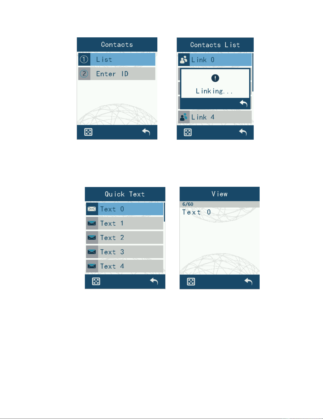
Continue to use the [Menu/confirmation key] to select “Contact List”, then select the target
contact in the contact list, and then use the [Menu/confirmation key] to send message. At
this time, the LCD shows the status of message sending.
16
Figure 21 Status message sending interface
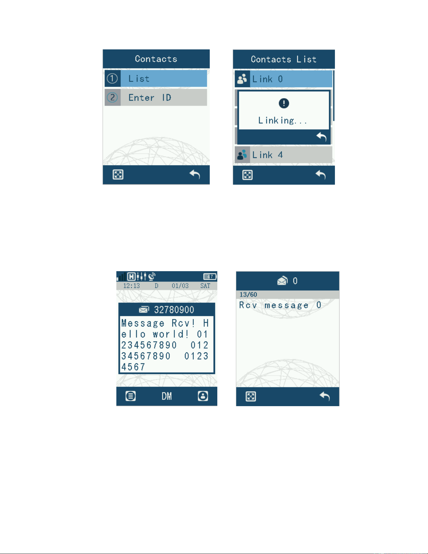
4.3.3 Shortcut text messaging
Enter the menu list, select “Message” -> “Quick Text”, enter the “Quick Text” list. In the list,
select the content with sending, use the [Menu/confirmation key] to view the specific
content of the status message.
Figure 22 Shortcut text messaging interface
Continue to use the [Menu/comfirmation key] to select “Contact List”, then select the target
contact in the contact list, and then use the [Menu/confirmation key] to send message. At
this time, the LCD shows the status of message sending.
17
Fig. 23 The sending shortcut text message interface
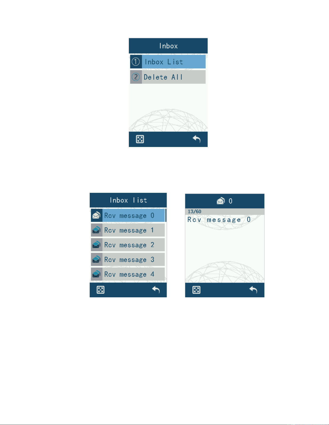
4.3.4 Text message reception
When you receive a text message that matches the local number, the local receiving group
list, the all-call number in the team, or the all-call number, the text message receiving
prompt box will pop up. Press [Return key] to return to the interface before receiving
message, and use [Menu/confirmation key] to reply, forward, delete and so on.
Figure 24 Message reception interface
4.3.5 Inbox
Inbox includes: Inbox List, Delete All.
18
Figure 25 Inbox interface
4.3.5.1 Inbox list
Enter the menu list, select “Message”-> “Inbox”-> “Outbox List”, enter the outbox message
content list. Use [Up] and [Down] keys to switch the list, and use [Menu/ confirmation key]
to enter the message content view interface.
Figure 26 Inbox list screen
For text messages, you can use the [Menu/confirmation key] to reply, forward, delete
and so on. For text messages, you can use the [Menu/confirmation key] to delete the
message. Inbox can be emptied of all incoming message.
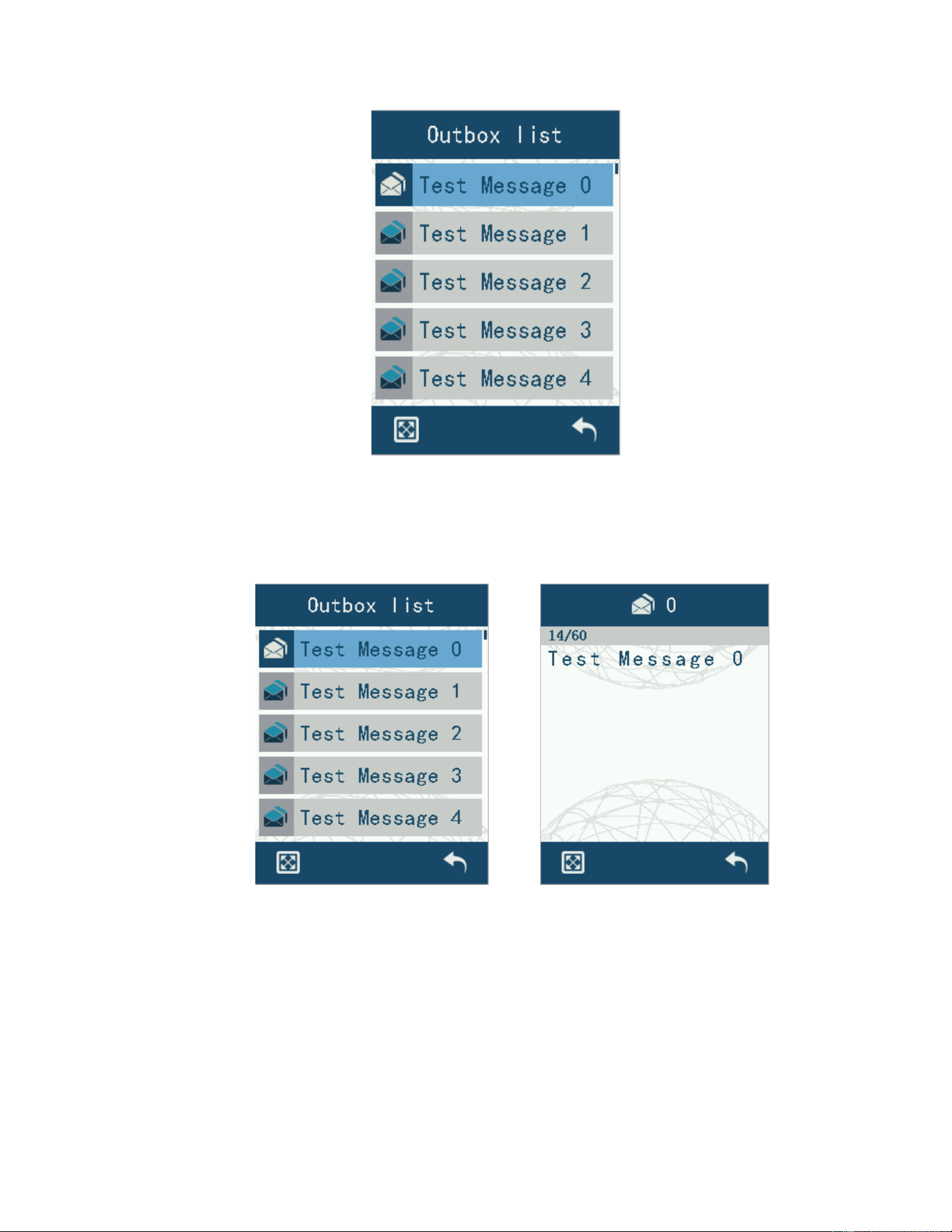
4.3.6 Outbox
Outbox Includes: Outbox List, Delete All.
19
Figure 27 Outbox interface
4.3.6.1 Sending lists
Enter the menu list, select “Message”-> “Outbox”-> “Outbox List”, enter the outbox
message content list. Use [Up] and [Down] keys to switch the list, and use
[Menu/confirmation key] to enter the message content view interface.
Figure 28 Outbox list screen
For text messages, you can use the [Menu/confirmation key] to resend, forward, delete
and other operations. For text messages, you can use the [Menu/confirmation key] to
delete the message. You can empty the outbox of all sent messages. The following is a list
of all the message that have been sent to the Outbox
20
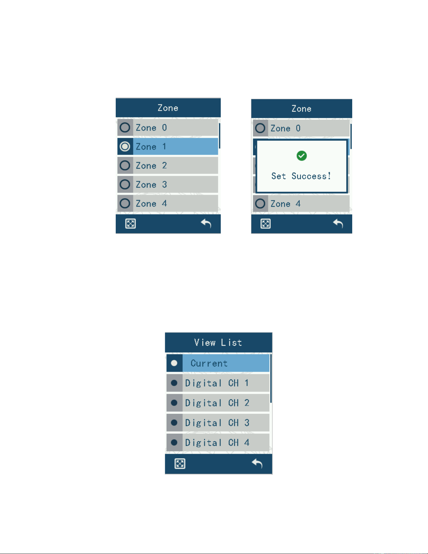
4.4 Zone selecting
Enter “Zone” to display the current radio zone list, you can select the desired zone in
the list, and switch to the zone to use.
Figure 29 Zone interfaces
4.5 Scanning Settings
In “Scan Settings”, if channel auto-scanning is on, you cannot manually turn off the
scan. If channel auto-scanning is off, you can manually turn scanning on or off. Three
options: open/close, view the list, set the effective list.
[On/Off] appears only when channel auto scanning is not turned on.
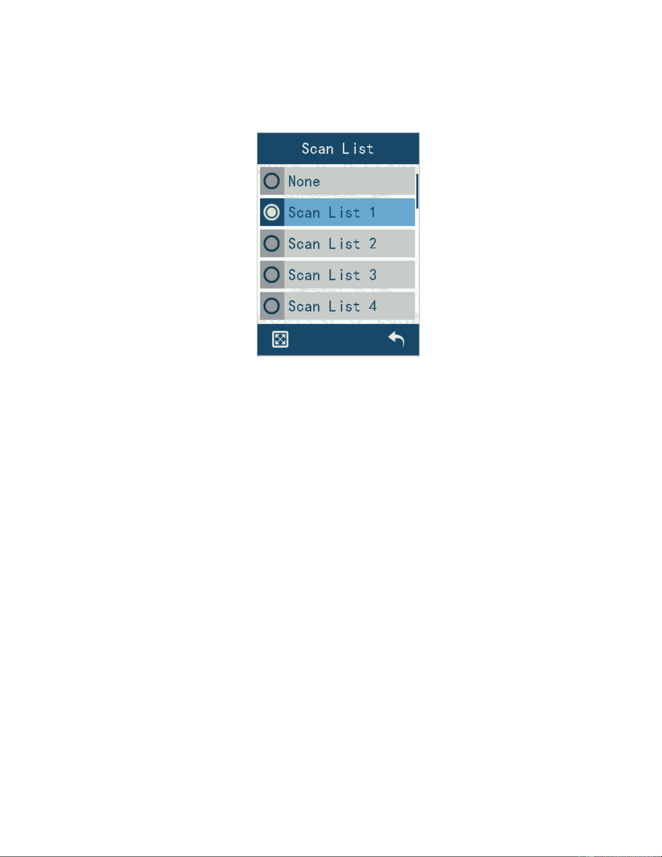
4.5.1 Viewing the list
Enter “View List” to see the scanning channels under the current scanning list.
Figure 30 Viewing the Scan Channel List screen
21
4.5.2 Setting up the active list
Entering “Scan List” allows you to switch and set the current channel scanning list.
Figure 31 The Scan List screen
4.6 Working modes
Radio operation mode selection, including "Conventional mode" and "Trunking mode".
Conventional mode: This mode includes digital and analog services in the direct mode (DM)
and repeater mode (RM).
Trunking mode: In this mode, the radio is registered to the system. Realize the functions of
group call, individual call, cross-area call and dispatch call for voice and data.
4.7 Other settings
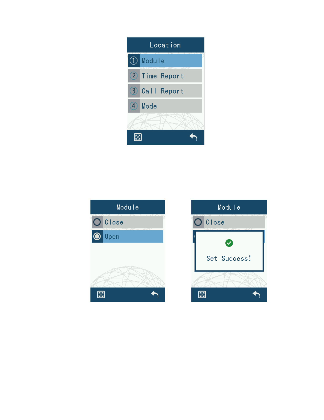
4.7.1 Positioning settings
The contents of “Location” are divided into four parts: module switch, time report, call
report, and positioning mode.
22
Figure 32 Positioning interface
4.7.1.1 Module switch
Entering “Module Switch” allows you to select the module to be turned on or off.
Figure 33 Positioning module switches
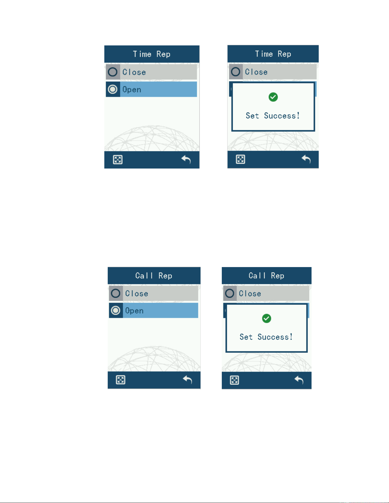
4.7.1.2 Timed reporting
Enter “Time Rep” to choose whether to turn on or off Timing Report. When Timed
Reporting is enabled, the device will periodically report the local positioning information to
the positioning receiving channel when positioning. The console can display the real-time
geographic location information of the device.
23
Figure 34 Timed Reporting Setup interface
4.7.1.3 Reporting with the call
You can choose to turn on or turn off the call report function by entering “Call Rep”.
When the Call Report function is on, the device will report the location information of the
device to the voice channel every time you make a call. The console can display the
geographic location information of the device in real time.
Fig. 35 The Call Reporting interface
4.7.2 Arbitrary calls
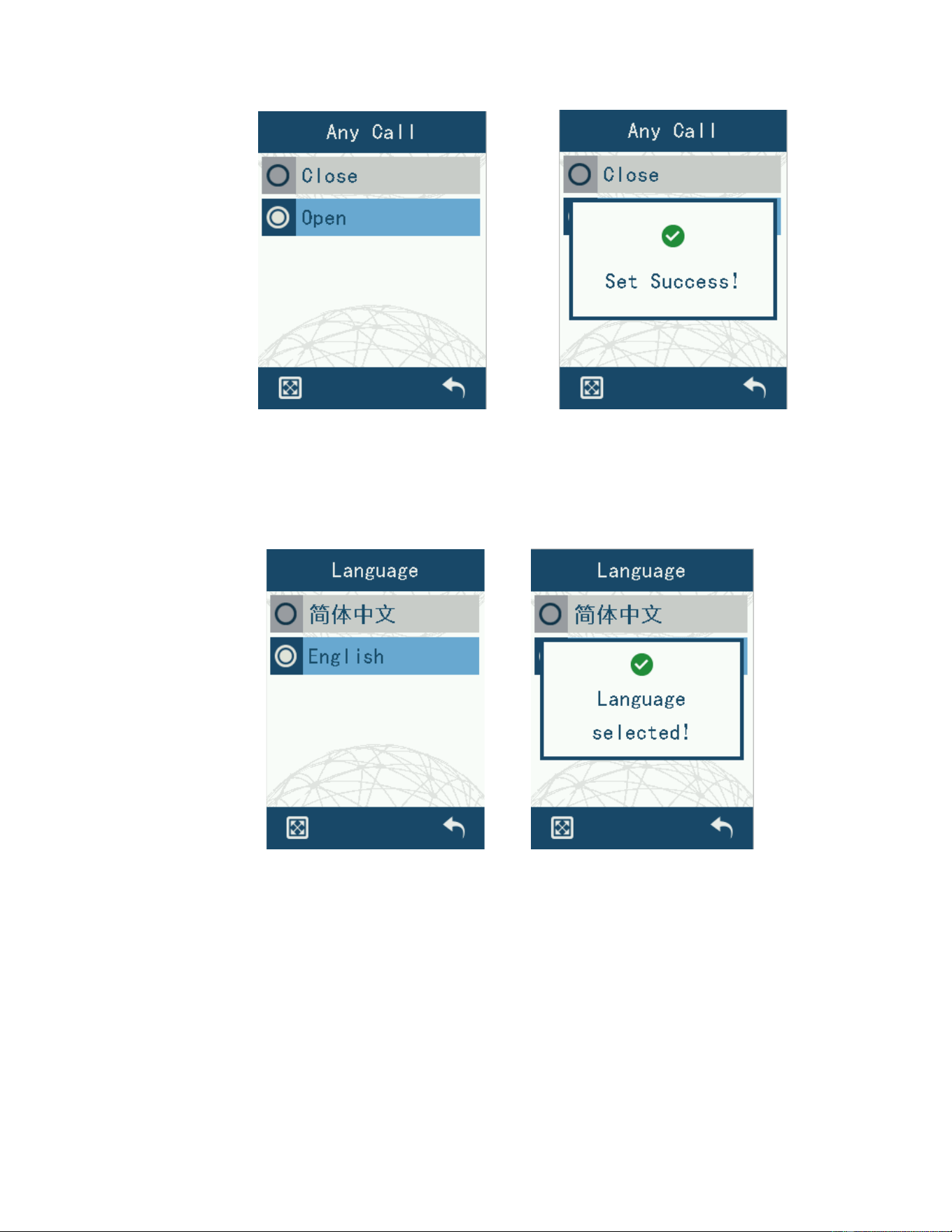
Entering “Any Call” you can choose to receive only group list calls and any meet protocol
calls.
24
Figure 36 Any call switch interface
4.7.3 Language settings
Enter “Language” to select Chinese Simplified Display and English Display.
Figure 37 Language selection screen
4.7.4 Power settings
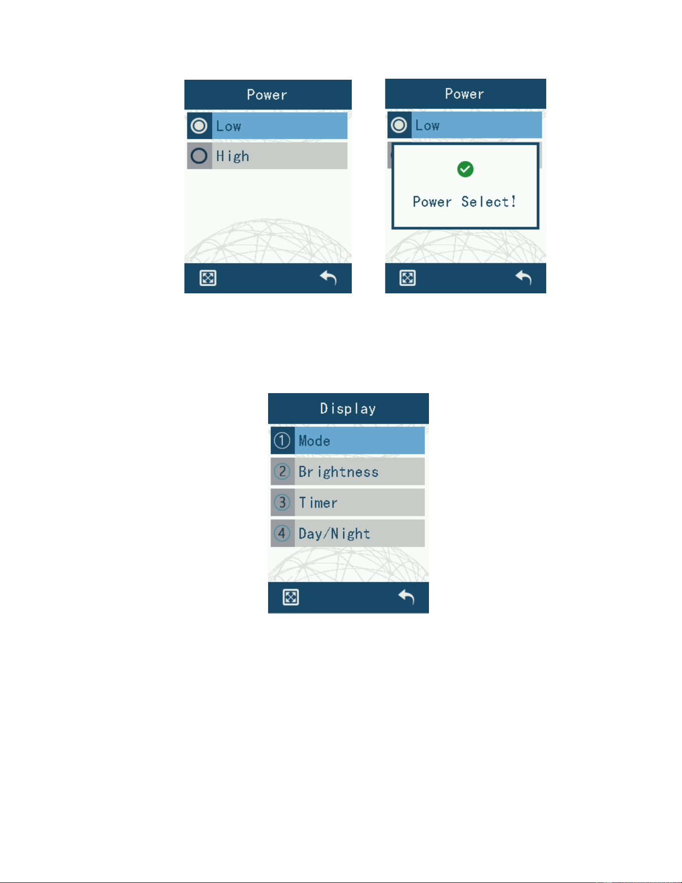
Enter to “Power Setting” to select high power and low power.
25
Figure 38 Power Selection interface
4.7.5 Display settings
The contents of “Display” are divided into four sections: Mode, Brightness, Timer,
Day/Night.
Figure 39 Display setup interface,
4.7.5.1 Backlight mode
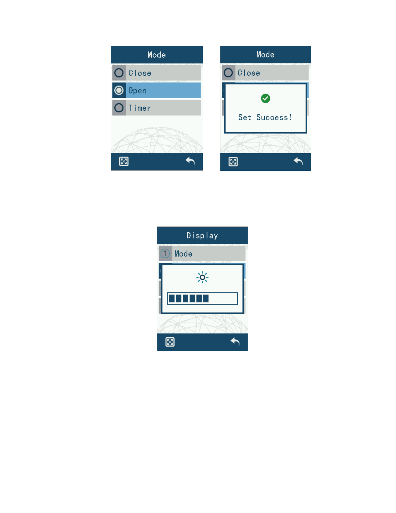
Entering “Mode” allows you to select Backlight Off, Backlight Normally On and Delayed Off.
The LCD backlight can be set to off, normally on and delayed off.
26
Figure 40 Backlight mode selection interface
4.7.5.2 Backlight brightness
Enter “Display” to adjust the LCD backlight brightness display.
Figure 41 Backlight Brightness Interface
4.7.5.3 Backlighting time
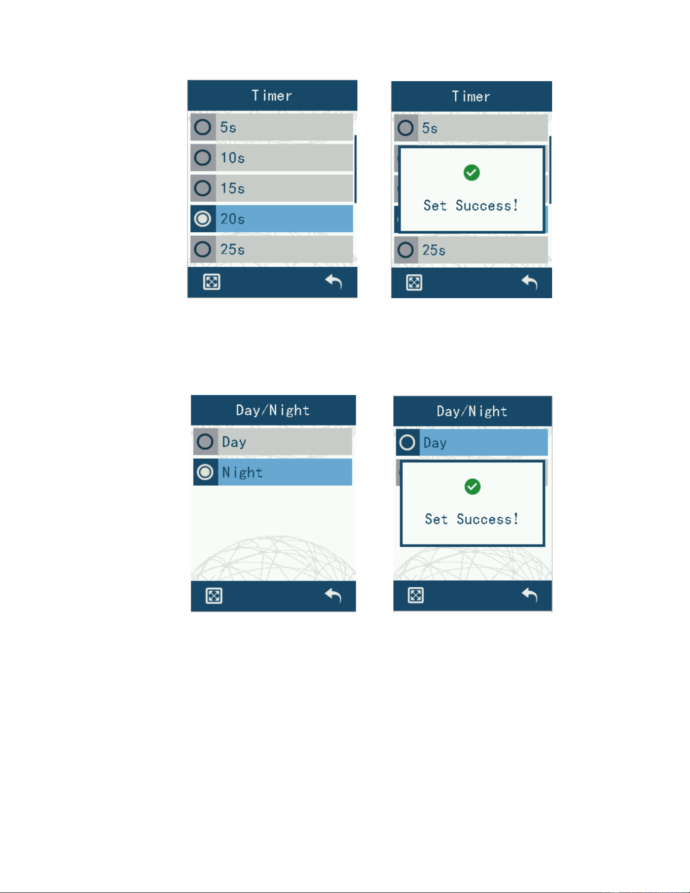
Enter “Timer” to adjust the backlight delay off time. The time is divided into 5s, 10s,
15s, 20s, 25s, 30s, 35s, 40s, 45s, 50s, 55s and 60s.
27
Figure 42 Backlight Time Setting interface
4.7.5.4 Day/Night
Entering “Day/Night” allows you to set the LCD mode to Day mode and Night mode.
Figure 43 Backlight Day/Night Settings interface
4.7.6 Beep settings
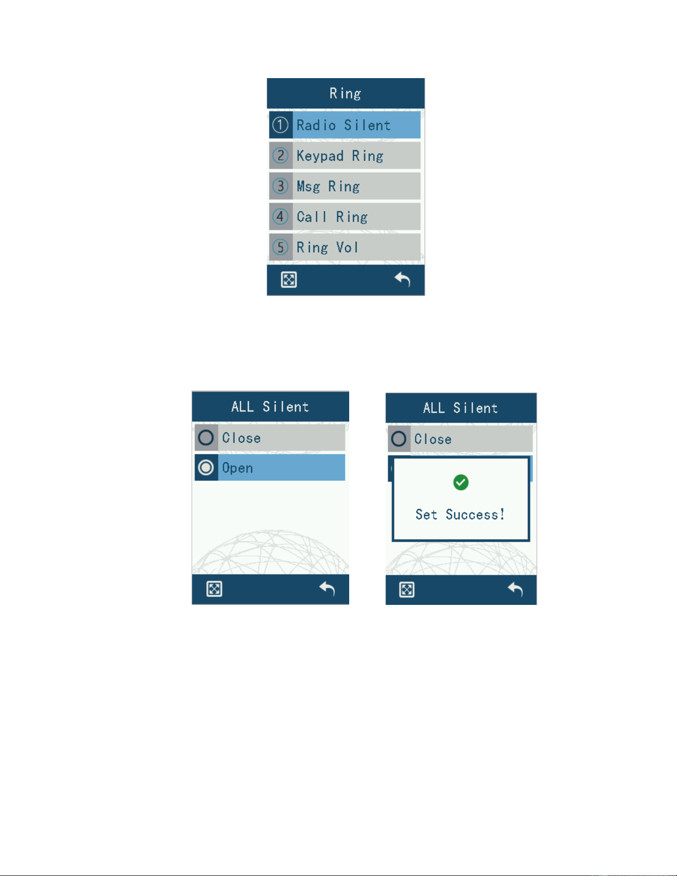
The content of “Ring” is divided into five parts: Radio Silent, keypad Ring, Msg ring,
Call ring and Ring vol.
28
Figure 44 Tone Settings screen
4.7.6.1 Radio Silent
Enter “All Silent” to select on and off. When the function is turned on, all beeps will be
disabled.
Figure 45 Radio silent Settings interface
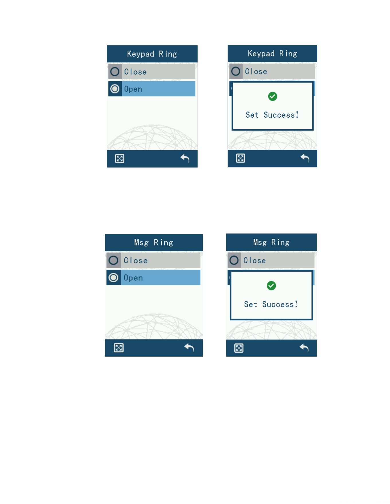
4.7.6.2 Key beeps
Enter “Keypad Ring” to select on or off. When the function is turned on, all key beeps will
be disabled.
29
Figure 46 Keypad ring setting interface
4.7.6.3 Message Ring
You can choose to turn on or off by entering “Msg Ring”. When the function is turned on, all
message beeps will be disabled.
Figure 47 Message ring setting interface
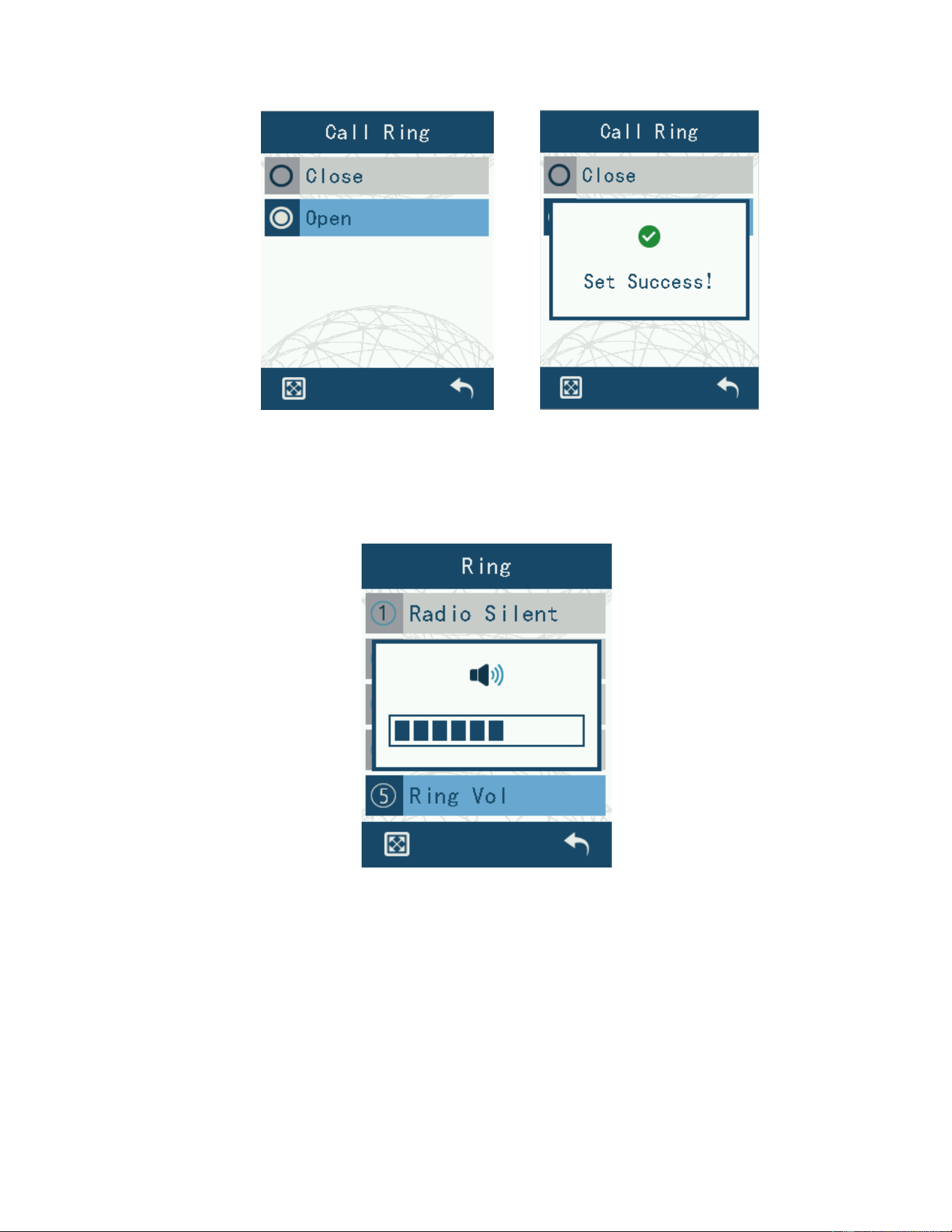
4.7.6.4 Call Ring
You can choose to turn on and off by entering “Call Ring”. When the function is turned on,
all call tones will be disabled.
30
Figure 48 Call ring setting interface
4.7.6.5 Ring volume
Enter “Ring” to adjust the beep volume level.
Figure 49 Ring volume setting interface
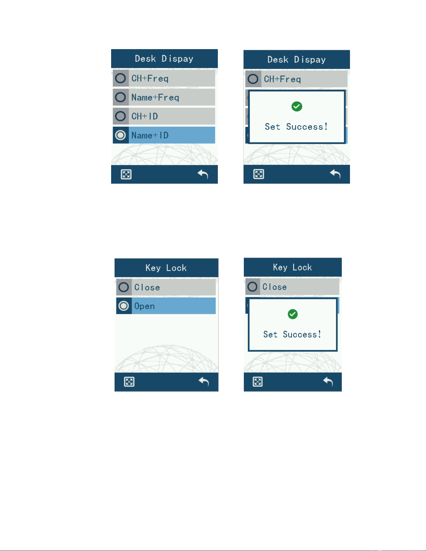
4.7.7 Standby Interface Settings
Entering “Desk Dispay” you can set the content of the guard interface display. You can
choose: CH+Freq, Name+Freq, CH+ID, Name+ID.
31
Figure 50 Standby Settings interface
4.7.8 Keypad lock setting
Enter the “Key Lock” to choose between on and off. After the function is turned on, the
keypad will be locked if you don't operate the keypad for a long time, and you need to
press the [*#] key to unlock it.
Figure 51 Keyboard Lock Settings screen
4.7.9 Time and date settings
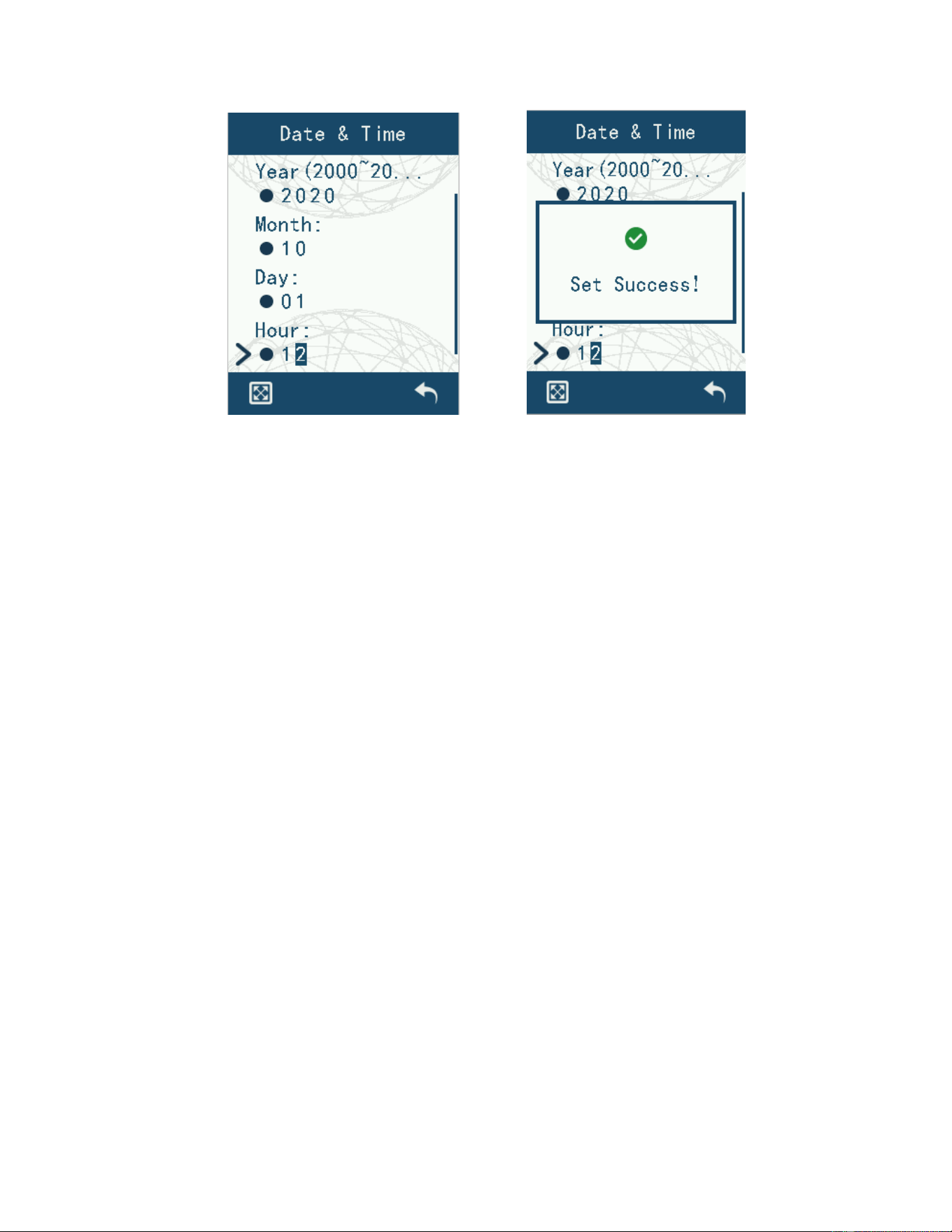
Enter “Date & Time” to set the time and date of the radio. The radio has an automatic time
calibration function, in the case of positioning module positioning, it will be automatically
calibrated to the positioning time.
32
Figure 52 Time and date setting interface
4.7.10 Short message type
Message type selection, including standard Motorola compatible IP compatible and M-
mode compatible.
4.7.11 Encryption settings
The contents of “Encryption” are divided into three sections: Encryption Type,
Encryption Enable and Encryption List.
Encryption type: including none, ordinary encryption, hardware encryption ARC4
encryption and AES256 encryption.
Encryption Enable: Includes off, voice only, data only, voice+data .
Encryption List: Used to display and select the list of keys that have been pre-set by the
Write Frequency software.
4.7.12 Show nearby devices
You can choose to turn it on or off by entering " Nearby Devices". When the function is
turned on, after receiving a call in digital conventional mode, you can see the relative
position and distance of the transmitter under the main display area. In addition, you can
view the latitude and longitude information of the transmitter by going to [Local Information]
- [Nearby Device Information].
4.7.13 Vibration settings
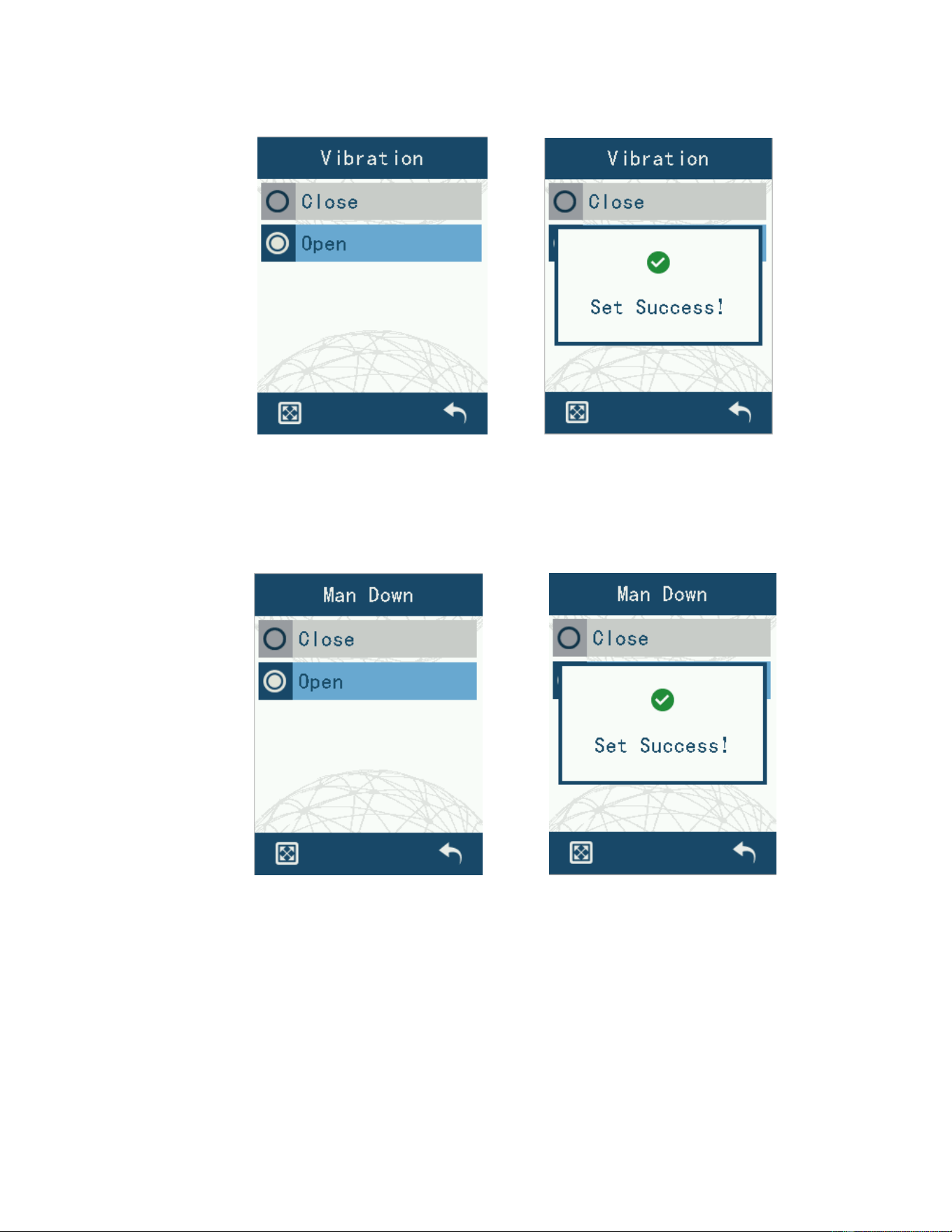
Entering “Vibration” you can choose to turn it on or off. When the function is turned on,
there will be vibration alerts when switching on and off, calling, and receiving message.
33
Figure 53 Vibration Settings interface
4.7.14 Man down setting
You can choose to turn it on or off by entering the “Man Down”. When the function is turned
on, there will be sound and light alarm when the device is tilted or placed upside down for a
long time.
Figure 54 Man down setting interface
4.7.15 Vocoder type
Vocoder type selection, including AMBE and NVOC.
4.7.16 Export of recordings
After connecting the data cable to the machine with the recording memory card installed
and the recording function enabled, entering this option will enter the recording file export
status. At this point, the computer will recognize the removable disk of the memory card.
34
4.8 Device information view
The content of “Device Info” is divided into six parts: local information, LCD board
information, positioning information, battery information, receiving group list and
neighboring device information.
4.8.1 Local Information View
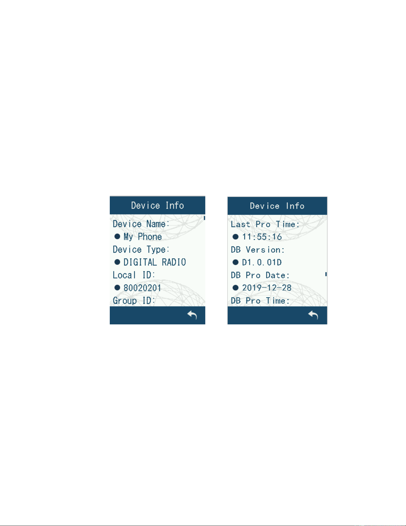
In “Device Info”, you can query the name of the station, the model number of the
device, the local number, the software version, the hardware version, the database version,
the serial number of the device, and other information.
Note: The following figure shows the information for the demonstration information,
specific equipment information according to the equipment native display information for
the real information.
Figure 55 Local Information Interface, the
4.8.2 LCD information view
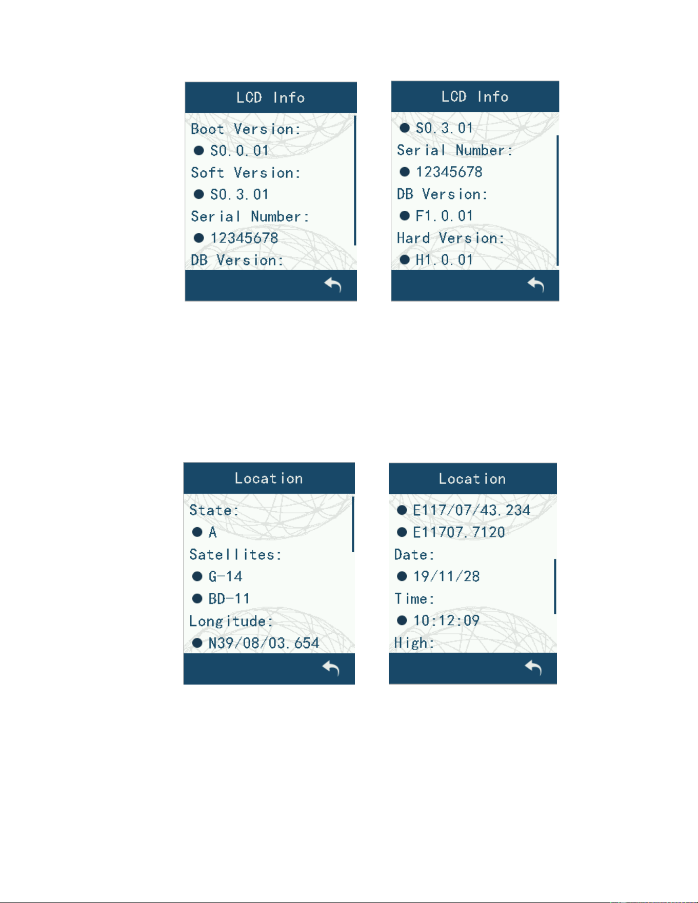
In “LCD Info”, you can query the LCD board software version number, LCD board
hardware version, LCD board database version, LCD board device serial number and other
information.
Note: The following figure shows the information for the demonstration information,
specific equipment information according to the equipment native display information for
the real information.
35
Figure 56 LCD information interface
4.8.3 Positioning information view
In “Location”, you can query the current radio positioning status, number of receiving
satellites, longitude, latitude, altitude, speed, navigation angle UTC time and date
information.
Note: The following figure shows the information for the demonstration information,
specific equipment information according to the equipment native display information for
the real information.
Figure 57 Positioning information interface
4.8.4 Battery information view
Battery Information allows you to query the current battery level information of the
intercom, which is displayed as a percentage sign.
36
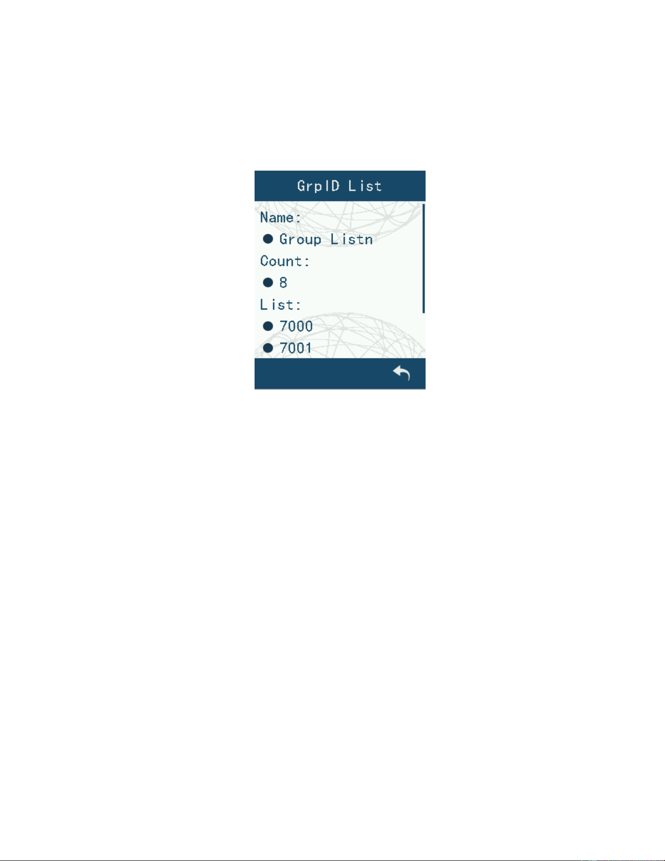
4.8.5 Receiving Group List View
In “GrpID List”, you can query the current device can receive group call list information.
Note: The following figure shows the information for the demonstration information,
specific equipment information according to the equipment native display information for
the real information.
Figure 58 Receive group list initerface
4.8.6 Proximity equipment information view
In " Nearby Devices", you can query the name ID number and longitude and latitude
information.
5. Routine maintenance of products
5.1 maintenance
In order to ensure better use, the hand-held table requires routine maintenance.
The battery is fully charged before use; monthly maintenance of the battery, when not in
use for a long time, the battery should be taken out and stored separately, and the battery
is placed halfway to prevent the phenomenon of battery loss.
The screen of the hand-held table is protected accordingly when it is in use, preventing
contact with sharp, pointed and corrosive objects, which may cause damage to the screen.
Cover the external connector with a protective cover when not in use to avoid damage
to the connector.
Replace or repair the antenna connector if rust appears.
4.2 Cleaning
Use a clean, dry, lint-free cloth or brush to wipe away dust on the surface of the product
and the charging pole piece on a regular basis.

37
The buttons, control knobs and housing of this product are very susceptible to soiling.
They can be cleaned with a neutral detergent and a non-woven cloth. Do not use
chemicals such as detergents, alcohol, sprays, or petroleum-based agents to avoid
damage to the surface and housing. After cleaning, make sure the product is thoroughly dry,
otherwise do not use it.
5. transportation and storage
5.1 Requirements and methods of packing equipment
A single set of hand-held table mainframe and spare accessories should be stored in a
box. Multiple sets of boxes can be unified into a strong, permanent wooden box with
handles on both sides for easy handling. Open the box does not require special tools, the
lid side of the locking buckle, release the locking buckle can be lifted off the lid of the
wooden box, revealing the box, take out the box, unpacking can be.
5.2 Transportation
Strictly install the transportation requirement operation on the packing box.
Loads are stacked neatly and securely so that the weight of the load does not exceed the
truck's load rating.
When loading trucks to meet the requirements of the relevant over-height, loading and
unloading boxes placed in a balanced manner, not allowed to be biased to one side.
(b) Not to allow through-vehicle shipments of flammable, explosive, or corrosive materials
The equipment should be protected from rain, sun, dust and impact during transportation.
Cover with canvas when transported in open trucks.
Equipment loading and dispatching shall be under the supervision of the ordering
In case of damage to equipment found during transportation and handling, notify the
relevant authorities in a timely manner
5.3 Storage
5.3.1 Storage rules
Equipment of different models and specifications are placed separately, stacked neatly,
not inverted
The packages shall be stacked on sleepers 30cm above the ground, with the stacking
height not more than 4.5m and the distance from the wall more than 1m to ensure air
circulation.
5.3.2 Requirements for warehouses
The warehouse complies with the following atmospheric conditions: temperature 5~30;
relative humidity: 50%~70%.
The warehouse shall have a certified cement floor, which shall be more than 40cm higher
than the floor
The warehouse should be free of harmful gases and corrosive substances packaging to
38
cause damage.
The warehouse should be well ventilated and dust-proofed and maintained.
5.3.3 Product storage period
The effective storage period of the equipment (except batteries) is at least 2 years,
and the batteries need to be charged and discharged every 6 months for maintenance.
Under the specified storage conditions, the technical performance of the equipment should
meet the requirements of the relevant standards or this specification and be free of
corrosion and mildew. Software recording media (CD-ROM, disk and chip and other
carriers) should be deterioration, damage and failure.
Caution:
1. Frequency: 400-470MHz, High power: 4W, Low power: 1W
2. RF exposure information: The device complies with RF exposure require when the device used at
25mm form your face and 0mm from the body with the belt-clips.
3. Declaration of Conformity.
Manufacturer: LISHENG COMMUNICATIONS CO., LTD.
Address: 5#, ChongXiang St., Econ & Tech. Area, Quanzhou, Fujian, China.
Hereby, LISHENG COMMUNICATIONS CO., LTD. declares that this product is in compliance
with essential requirements and other relevant provisions of Directive 2014/53/EU. This product
is allowed to be used in all EU member states.
4. AC adapter
The adapter shall be installed near the equipment and shall be easily accessible.
5. Lithium Battery
Risk of explosion if battery is replaced by an incorrect type, dispose of used battery according
to the instructions.
Engineering personnel setting up those frequency ranges whit Customer Programming Software,
the mechanism implemented in the product to avoid the end user to managing changes in the
definition of operating frequency ranges in order to avoid usage of un-allowed frequency ranges.
The authorized to set up the permitted frequency ranges for marketing in the specific country:
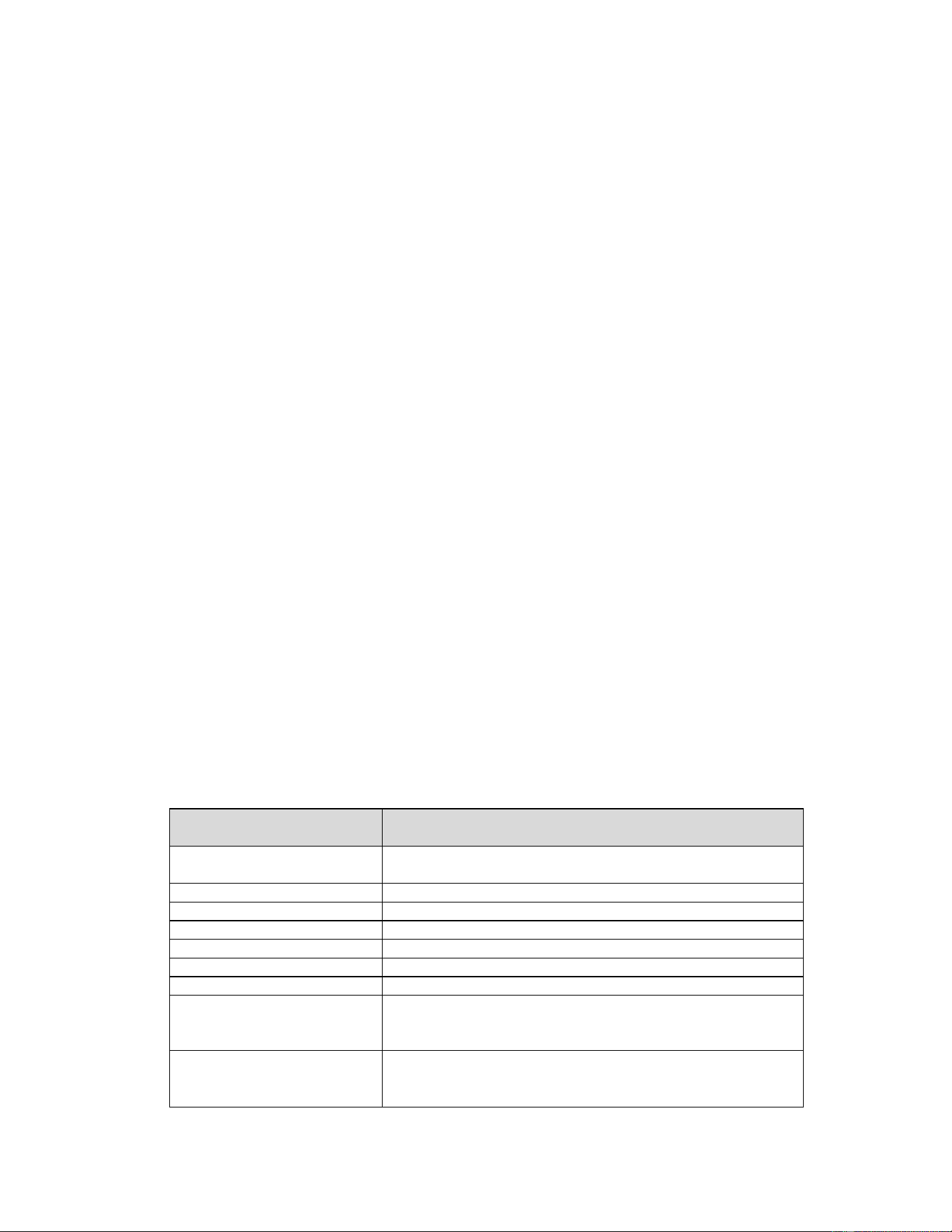
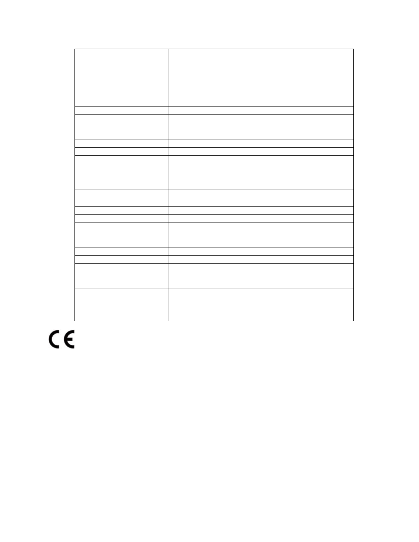
Country Frequency Range(MHz)
Austria(AT)
444.9 - 444.900001, 450 - 456, 457.33 - 457.330001,
457.45 - 458.3,460 -470
Belgium(BE)
406.1-430 ,440-470
Bulgaria(BG)
410 -430,440-470
Croatia (HR)
406.1-430 ,440-470
Cyprus (CY)
406.1-430 ,440-470
Czech Republic (CZ)
448 - 451.3 ,457.38 - 461.3 ,467.38 - 470
Denmark(DK)
406.1-430 , 450 - 470
Estonia(EE)
406.1 - 410,412.5 - 420 , 422.5-430 ,440 - 442.5,
443 - 450,446 -446.2,450 -453 ,457.575 - 463,467.575 -
470
Finland(FI)
407.525 - 408.55,410.0125 - 410.8875,417.525 - 417.9,
419.15 - 419.525,419.55625 - 419.71875,420.0125 -
420.8875,426.35 - 427.5,427.525 - 427.9, 429.15 -
39
429.525,429.55625- 429.71875,440.0125 - 440.5875,
440.60625 - 440.89375,442.775 - 443, 443.025 - 444,
444.025 - 444.525,444.55 - 444.975,445 - 446,
447.00625 - 447.29375,447.30625 - 447.70625,
449.025 - 449.525,449.55 - 449.975, 450.325 - 452.475,
452.525 - 452.975,453.0125 - 453.6625,469.725 -
469.975
France (FR)
406.1-430,444.5-447, 451.5-460, 461.5-470
Germany(DE)
406.1-430 ,440-470
Greece(EL)
406.1-430 ,440-470
Hungary(HU)
417 - 420,442 - 445,456 - 460, 461.3 - 470
Ireland (IE)
410 - 430,440 - 455, 456 - 459,460 - 470
Italy(IT)
440-443,445-470
Latvia (LV)
406.1-430,440-450,456 -470
Lithuania(LT)
406.1 - 410 , 413 - 418.6 ,423- 428.6 ,440 - 450 ,
450 - 452.9875 ,458.1125 - 462.9875 ,467.4875 -
467.5875
Luxembourg (LU)
410-430,440- 470
Malta(MT)
406.1-430 ,440-470
Netherlands(NL)
410 -430,440-470
Poland(PL)
448 - 449.5,457 - 460,467 - 470
Portugal (PT)
148 - 149.9,150.05 - 156.4875 , 156.8375 - 174
Romania(RO)
408 - 410.8,415 - 420.8,425 - 429.8, 440 - 450.55,
457.5 - 458.2, 460 - 460.55,467.5 - 468.2
Slovakia(SK)
441.025 - 451.31,455.73 - 461.31,465.73- 470
Slovenia(SI)
406.1-430 ,440-470
Spain(ES)
406.1-430 ,440-470
Sweden(SE)
406.1 -430, 442 - 444,444.5875 - 452.5,
457.5 - 462.5,467.5 - 470
United Kingdom (UK)
400-470
USA 400-470

40
FCC STATEMENT:
Any Changes or modifications not expressly approved by the party responsible for
compliance could void the user's authority to operate the equipment.
RF Exposure Statement:
SAR tests are conducted using standard operating positions accepted by FCC with the
device transmitting at its highest certified power level in all tested frequency bands,
although the SAR is determined at the highest certified power level, the actual SAR level of
the device while operating can be well below the maximum value. Before a new model is
an available for sale to the public, it must be tested and certified to the FCC that is does not
exceed the exposure limit established by the FCC. Tests for each product are performed in
positions and locations as required by the FCC. For body worn operation, this device has
been tested and meets the FCC RF exposure guidelines when used with and accessory
designated for this product or when used with and accessory that contains no metal. To
maintain compliance with FCC RF exposure guidelines, hold the transmitter and antenna at
least 1 inch (2.5 centimeters) from your face and speak in a normal voice, with the antenna
pointed up and away from the face.
Note: This equipment has been tested and found to comply with the limits for a Class B
digital device, pursuant to part 15 of the FCC Rules. These limits are designed to provide
reasonable protection against harmful interference in a residential installation. This
equipment generates, uses and can radiate radio frequency energy and, if not installed and
used in accordance with the instructions, may cause harmful interference to radio
communications. However, there is no guarantee that interference will not occur in a
particular installation. If this equipment does cause harmful interference to radio or
television reception, which can be determined by turning the equipment off and on, the
user is encouraged to try to correct the interference by one or more of the following
measures:
-Reorient or relocate the receiving antenna
-Increase the separation between the equipment and receiver.
-Connect the equipment into an outlet on a circuit different from that to which the receiver is
connected.
-Consult the dealer or an experienced radio/TV technician for help.
This device complies with part 15 of the FCc Rules. Operation is subject to the condition that
this device does not cause harmful interference.

41
WARNING: MODIFICATION OF THIS DEVICE TO RECEIVE CELLULAR
RADIOTELEPHONE SERVICE SIGNALS IS PROHIBITED UNDER FCC RULES AND
FEDERAL LAW.